

Page 1

CLX490
Compact OMNI Scanner
for Bar Codes
Omni Line
OPERATING INSTRUCTIONS
Page 2

Software versions
CLX490 Compact OMNI Scanner
Operating Instructions
Software versions
Software/Tool Function Version
CLX490 Firmware V 5.0 RA32
CLV-Setup Configuration software (windows-based) V 4.4 QF16
CLV-Setup Help Online help (HTML) V 4.4 QF16
Copyright
Copyright © 2004 - 2007
SICK AG Waldkirch
Auto Ident, Reute Plant
Nimburger Strasse 11
79276 Reute
Germany
Trademarks
TM
Windows 95
TM
Explorer
are registered trademarks or trademarks of the Microsoft Corporation in the USA
TM
/98
, Windows NTTM, Windows 2000TM, Windows XPTM and Internet
and other countries.
Acrobat
TM
ReaderTM is a trademark of the Adobe Systems Incorporated.
Latest manual version
For the latest version of this manual (PDF), see www.sick.com.
I-2 © SICK AG · Division Auto Ident · Germany · All rights reserved 8009237/RB47/2007-08-03
Page 3

Operating Instructions
CLX490
Quick Finder
CLX490 Compact OMNI Scanner
Quick Finder
• What is delivered with the device
– Chapter 3.1.1 Scope of delivery, Page 3-1
• CAUTION!
– Chapter 2 Safety information, Page 2-1
• Mounting the device at the reading station
– Chapter 4 Installation, Page 4-1
• Connecting the device
– Chapter 5 Electrical installation, Page 5-1
• Overview of the device and its functions
– Chapter 3 Product description, Page 3-1
– Chapter 6.2 Default settings, Page 6-1
– Chapter 6.5 Operating modes and outputing the reading result, Page 6-14
– Chapter 9 Technical data, Page 9-1
– Chapter 10.3 Installing and operating the external parameter memory, Page 10-8
• Starting the device with the default settings
– Chapter 6.3 Quick start, Page 6-3
• Installing the "CLV-Setup" program
– Chapter 10.6 Installing and operating the "CLV-Setup" program, Page 10-15
• Adapting the device to the reading application
– Chapter 6.4 Configuring (parameterization) the CLX, Page 6-4
• Troubleshooting
– Chapter 8 Troubleshooting, Page 8-1
• Finding information
– Table of contents, Page I -5
– Index, Page 10 -49
8009237/RB47/2007-08-03 © SICK AG · Division Auto Ident · Germany · All rights reserved I-3
Page 4

Quick Finder
CLX490 Compact OMNI Scanner
Operating Instructions
Installation procedure (overview)
Reading pulses via switching input "Sensor" (default setting)
1. Check the delivery to make sure that none of the components is missing.
2. Mount the CLX at the reading station and align it with the object carrying the bar code.
3. Mount the AMV/S60 Connection Module.
4. Connect the CLX to the AMV/S60 Connection Module using the two cables
no. 2020302. Alternatively, connect the device to the AMV/S60 via the external
parameter memory no. 2020307.
5. Connect the reading pulse sensor to the "Sensor" switching input in the AMV/S60.
6. Connect the host to the host interface in the AMV/S60.
Adapt the AMV/S60 to the host interface type of the CLX.
7. Switch on the power supply to the AMV/S60.
The "Device Ready" LED lights up after the CLX has started.
CLX with external parameter memory (in connector cover) connected:
After the CLX has started, it copies the internal parameter set to the external parameter
memory if the memory is empty. Then the "Read Result" LED lights up.
8. Switch on your PC and start Windows
9. Install the "CLV-Setup" software and online CLV-Setup Help from the CD-ROM ("Manuals & Software") on your PC.
10. Connect the PC to the auxiliary interface of the CLX. To do so, connect the 3-core
RS 232 data cable (null modem cable) (e. g. no. 2014054) to the "Service plug" in the
AMV/S60.
11. Start the "CLV-Setup" program.
CLV-Setup establishes communication with the CLX and uploads the parameter set.
The parameters are then displayed on the tabs.
12. Carry out a test read using test bar codes (trigger the CLX accordingly).
Display the reading result in the Terminal Emulator window of the "CLV-Setup" program.
13. Configure the CLX for the application using the settings on the tabs in CLV-Setup. Copy
(download) the modified parameter set to the CLX temporarily.
Do not switch off the power to the AMV/S60 (CLX)!
14. Test the application under realistic conditions.
15. Check whether the data is transmitted correctly between the CLX and host.
16. If necessary, correct and optimize the parameter values.
Copy (download) the parameter set permanently to the CLX.
CLX with external parameter memory (in connector cover) connected:
Copy the modified parameter set to the external parameter memory when CLV-Setup
asks you for confirmation.
17. Save the parameter set as a configuration file "*.scl" in the "CLV-Setup" program.
TM
(minimum requirement: Windows 95TM).
The CLX can then be operated with the application-specific settings.
I-4 © SICK AG · Division Auto Ident · Germany · All rights reserved 8009237/RB47/2007-08-03
Page 5

Operating Instructions
CLX490
Contents
Table of contents
1 Notes on this document............................................................................................ 1-1
1.1 Purpose ....................................................................................................................................... 1-1
1.2 Target audience........................................................................................................................ 1-1
1.2.1 Mounting, electrical installation, maintenance and replacement.................... 1-1
1.2.2 Startup, operation and configuration ......................................................................... 1-1
1.3 Information content................................................................................................................. 1-1
1.4 Symbols ....................................................................................................................................... 1-2
2 Safety information....................................................................................................... 2-1
2.1 Authorized users ...................................................................................................................... 2-1
2.1.1 Mounting and maintenance .......................................................................................... 2-1
2.1.2 Electrical installation and replacement ..................................................................... 2-1
2.1.3 Startup, operation and configuration ......................................................................... 2-1
2.2 Intended use.............................................................................................................................. 2-1
2.3 General safety instructions and protection measures .............................................. 2-2
2.4 Quick stop and quick restart................................................................................................ 2-4
2.4.1 Stopping the CLX............................................................................................................... 2-4
2.4.2 Restarting the CLX ............................................................................................................ 2-4
2.5 Environmental information....................................................................................................2-4
2.5.1 Power requirements.........................................................................................................2-4
2.5.2 Disposal after removal from service.......................................................................... 2-4
3 Product description .................................................................................................... 3-1
3.1 Design .......................................................................................................................................... 3-1
3.1.1 Scope of delivery............................................................................................................... 3-1
3.1.2 Variants ................................................................................................................................. 3-1
3.1.3 System requirements ...................................................................................................... 3-1
3.1.4 Design ................................................................................................................................... 3-3
3.2 Method of operation............................................................................................................... 3-4
3.2.1 Autofocus function............................................................................................................ 3-5
3.2.2 Event-controlled dynamic focus control ................................................................... 3-6
3.2.3 Additional components ................................................................................................... 3-6
3.3 Indicators and control elements ........................................................................................ 3-7
3.3.1 Control elements............................................................................................................... 3-7
3.3.2 Function of the LEDs........................................................................................................ 3-7
4 Installation..................................................................................................................... 4-1
4.1 Installation sequence ............................................................................................................. 4-1
4.2 Preparations............................................................................................................................... 4-1
4.2.1 Required components..................................................................................................... 4-1
4.2.2 Required accessories...................................................................................................... 4-1
4.2.3 Required auxiliary parts .................................................................................................. 4-1
4.2.4 Replacing the laser warning label ............................................................................... 4-2
4.2.5 Selecting the mounting location .................................................................................. 4-2
4.2.6 Mounting accessories ..................................................................................................... 4-3
4.2.7 Distance between the CLX and the object ............................................................. 4-4
4.2.8 Count direction of the reading angle RA .................................................................. 4-5
4.3 Mounting and adjusting the device ................................................................................... 4-6
4.3.1 Mounting the CLX.............................................................................................................. 4-6
4.3.2 Adjusting the CLX .............................................................................................................. 4-6
4.4 Mounting the external components.................................................................................. 4-8
4.4.1 Mounting the AMV/S60 Connection Module ......................................................... 4-8
4.4.2 Mounting the external reading pulse sensor.......................................................... 4-8
4.4.3 Mounting the sensors for detecting the object distance................................... 4-9
4.5 Dismantling the device ........................................................................................................4-10
5 Electrical installation ................................................................................................. 5-1
5.1 Installation sequence ............................................................................................................ 5-1
5.1.1 SICK Connection Modules (overview) ..................................................................... 5-1
8009237/RB47/2007-08-03 © SICK AG · Division Auto Ident · Germany · All rights reserved I-5
Page 6

Contents
CLX490 Compact OMNI Scanner
5.2 Electrical connections and cables .....................................................................................5-2
5.2.1 Wire cross-sections .......................................................................................................... 5-2
5.2.2 Prefabricated cables (overview) ..................................................................................5-2
5.2.3 Connections/cables for the AMV/S Connection Module ................................... 5-3
5.2.4 Connections/cables for the Bus Connection Modules
BMV10 and BMS20 ......................................................................................................... 5-4
5.2.5 Connections/cables for the external parameter memory
(connection to AMV/S or BMV10/BMS20).............................................................5-4
5.2.6 Connections/cables for the IP 65 connector cover
(connection to AMV100/200 or BMV10) ...............................................................5-5
5.3 Connector pin assignment....................................................................................................5-6
5.3.1 Terminals on the CLX .......................................................................................................5-6
5.3.2 External parameter memory no. 2020307/2021689
(optional accessory)
connector cover no. 2021298 (optional accessory)..........................................5-7
5.4 Preparations for electrical installation............................................................................... 5-8
5.4.1 Requirements for the host interface ..........................................................................5-8
5.4.2 Supply voltage .................................................................................................................... 5-8
5.4.3 Non-SICK Power supply unit/connections without the
Connection Module........................................................................................................... 5-9
5.5 Electrical installation procedur.......................................................................................... 5-13
5.5.1 Individual steps................................................................................................................ 5-13
5.5.2 Tools.................................................................................................................................... 5-13
5.5.3 Connecting the supply voltage .................................................................................. 5-13
5.5.4 Connecting the host interface ................................................................................... 5-14
5.5.5 Connecting the CAN interface ................................................................................... 5-15
5.5.6 Connecting the PC..........................................................................................................5-15
5.5.7 Connecting the switching inputs ............................................................................... 5-16
5.5.8 Connecting the "Result 1 to Result 2" switching outputs...............................5-19
6 Operation ....................................................................................................................... 6-1
6.1 Overview of steps for starting up the CLX ...................................................................... 6-1
6.2 Default settings .........................................................................................................................6-1
6.2.1 Default settings of the CLX490 ................................................................................... 6-2
6.3 Quick start ................................................................................................................................... 6-3
6.3.1 Switching the CLX on for the first time with the factory default settings...... 6-3
6.4 Configuring (parameterization) the CLX ........................................................................... 6-4
6.4.1 Configuring the CLX with CLV-Setup........................................................................... 6-4
6.4.2 Function of the tabs in CLV-Setup (overview) ........................................................6-6
6.4.3 Guide to parameterization menu.................................................................................6-8
6.5 Operating modes and outputing the reading result ................................................. 6-14
6.5.1 Reading mode (standard operating mode).......................................................... 6-14
6.5.2 Percentage evaluation .................................................................................................. 6-17
6.5.3 Background teach-in ..................................................................................................... 6-19
6.5.4 Displaying and editing operating data .................................................................... 6-21
6.5.5 Reading diagnosis ..........................................................................................................6-21
6.5.6 Monitor Host Interface.................................................................................................. 6-22
6.5.7 Auxiliary input.................................................................................................................... 6-24
6.5.8 Self-test .............................................................................................................................. 6-24
6.5.9 Executing CLX functions interactively...................................................................... 6-25
6.6 CLX messages........................................................................................................................ 6-25
6.6.1 Displaying messages .................................................................................................... 6-25
6.7 Switching off the CLX ........................................................................................................... 6-26
7 Maintenance ................................................................................................................. 7-1
7.1 Maintenance during operation ............................................................................................7-1
7.2 Cleaning the CLX....................................................................................................................... 7-1
7.2.1 Cleaning the front window .............................................................................................. 7-1
7.2.2 Cleaning other optical surfaces.................................................................................... 7-2
Operating Instructions
I-6 © SICK AG · Division Auto Ident · Germany · All rights reserved 8009237/RB47/2007-08-03
Page 7

Operating Instructions
CLX490
Contents
7.3 Checking the incremental encoder ................................................................................... 7-3
7.4 Disposal....................................................................................................................................... 7-3
8 Troubleshooting ........................................................................................................... 8-1
8.1 Overview of the possible errors and malfunctions...................................................... 8-1
8.1.1 Mounting errors ................................................................................................................. 8-1
8.1.2 Electrical installation errors............................................................................................ 8-1
8.1.3 Parameter errors............................................................................................................... 8-1
8.1.4 Malfunctions........................................................................................................................ 8-1
8.2 Monitoring error and malfunctions .................................................................................... 8-1
8.3 Error messages ........................................................................................................................ 8-2
8.3.1 CLX without external parameter memory................................................................ 8-2
8.3.2 LED error messages for the external parameter memory................................ 8-3
8.3.3 Messages for errors accessing the external parameter memory ................. 8-5
8.4 ST error status in the reading result of a bar code..................................................... 8-7
8.5 Troubleshooting ........................................................................................................................ 8-9
8.5.1 General malfunctions: CLX not ready ........................................................................ 8-9
8.5.2 Malfunctions in Reading mode: reading trigger errors......................................8-10
8.5.3 Malfunctions in Reading mode: result output errors.........................................8-11
8.5.4 Malfunctions in Reading mode: errors in the result status output...............8-13
8.6 SICK Support ...........................................................................................................................8-14
9 Technical data .............................................................................................................. 9-1
9.1 Data sheet CLX490-0010 Compact OMNI Scanner ................................................. 9-1
9.2 Data sheet CLX490-0011 Compact OMNI Scanner ................................................. 9-2
9.3 Dimensioned drawing of the CLX....................................................................................... 9-2
10 Appendix ..................................................................................................................... 10-1
10.1 Overview ....................................................................................................................................10-1
10.2 Specification diagrams.........................................................................................................10-1
10.2.1 Reading conditions for all diagrams.........................................................................10-1
10.2.2 Reading performance data CLX490 Compact OMNI Scanner .....................10-2
10.2.3 Reading field and system dimensions ....................................................................10-4
10.3 Installing and operating the external parameter memory......................................10-8
10.3.1 Function ..............................................................................................................................10-8
10.3.2 Installation and electrical connection ......................................................................10-9
10.3.3 Operation............................................................................................................................10-9
10.3.4 Switching on the device for the first time ...........................................................10-10
10.3.5 Adjusting the parameter set in the external parameter memory
after it has been downloaded to the CLX ...........................................................10-10
10.3.6 Meaning of the LEDs ..................................................................................................10-11
10.3.7 Error messages ............................................................................................................10-11
10.3.8 Replacing a CLX ............................................................................................................10-11
10.4 Optional heating...................................................................................................................10-12
10.4.1 Features...........................................................................................................................10-12
10.4.2 Design ..............................................................................................................................10-12
10.4.3 Function ...........................................................................................................................10-12
10.4.4 Electrical installation....................................................................................................10-13
10.4.5 Outdoor applications...................................................................................................10-13
10.5 System messages..............................................................................................................10-14
10.5.1 CLX without external parameter memory ...........................................................10-14
10.5.2 CLX with external parameter memory connected...........................................10-14
10.6 Installing and operating the "CLV-Setup" program ................................................10-15
10.6.1 Preparations...................................................................................................................10-15
10.6.2 Installing the software ................................................................................................10-15
10.6.3 Starting CLV-Setup ......................................................................................................10-18
10.6.4 User interface ................................................................................................................10-20
10.6.5 Functions .........................................................................................................................10-21
10.6.6 Hot keys...........................................................................................................................10-21
10.6.7 Opening and closing tabs..........................................................................................10-22
8009237/RB47/2007-08-03 © SICK AG · Division Auto Ident · Germany · All rights reserved I-7
Page 8

Contents
CLX490 Compact OMNI Scanner
10.6.8 CLV-Setup Help ............................................................................................................10-22
10.6.9 Transferring parameter sets between CLV-Setup and the CLX ................ 10-23
10.6.10 Unknown parameters................................................................................................. 10-23
10.6.11 Log file in the Terminal Emulator ........................................................................... 10-24
10.6.12 Starting CLV-Setup with an "INI file" as an argument.................................... 10-24
10.6.13 The CLV Assistant........................................................................................................10-24
10.7 Configuring a CLX with command strings.................................................................. 10-25
10.8 Calculating parameter values for setting the CLX.................................................. 10-27
10.8.1 Calculating the necessary capture area for the bar code if
several bar codes are read on each object ...................................................... 10-27
10.9 Tables ..................................................................................................................................... 10-28
10.9.1 Calculating the code length of a bar code......................................................... 10-28
10.10 Special applications and procedures ......................................................................... 10-29
10.10.1 Auxiliary input via auxiliary interface ..................................................................... 10-29
10.10.2 Connection to the Profibus DP ............................................................................... 10-32
10.10.3 Connection to the DeviceNet.................................................................................. 10-32
10.10.4 Connection to Interbus-S.......................................................................................... 10-32
10.10.5 Connection to Ethernet TCP/IP .............................................................................. 10-32
10.10.6 Building a CAN Scanner Network .......................................................................... 10-32
10.10.7 Integration in an OPS reading system ................................................................. 10-32
10.11 Replacing a CLX (copying the parameter set)......................................................... 10-33
10.11.1 Downloading the parameter set............................................................................ 10-33
10.11.2 Importing the parameter set from the external memory ............................. 10-34
10.12 Ordering information.......................................................................................................... 10-35
10.12.1 CLX490 Compact OMNI Scanner ......................................................................... 10-35
10.12.2 Accessories: Mounting accessories..................................................................... 10-35
10.12.3 Accessories: Connection modules ....................................................................... 10-35
10.12.4 Accessories: Bus connection modules ............................................................... 10-36
10.12.5 Cables, external parameter memories and plug cover ................................ 10-37
10.12.6 Plug-in connections..................................................................................................... 10-38
10.12.7 Reading pulse generators........................................................................................ 10-38
10.13 Dimensioned drawings of the accessories .............................................................. 10-39
10.13.1 Angle bracket, no. 2022996 .................................................................................. 10-39
10.14 Supplementary documentation .................................................................................... 10-40
10.14.1 CLV Connect (from version 1.9) ............................................................................ 10-40
10.15 Glossary ................................................................................................................................. 10-41
10.16 EC Declaration of Conformity......................................................................................... 10-47
10.17 Index........................................................................................................................................ 10-49
10.18 Bar code example.............................................................................................................. 10-53
Operating Instructions
I-8 © SICK AG · Division Auto Ident · Germany · All rights reserved 8009237/RB47/2007-08-03
Page 9

Operating Instructions
CLX490
Figures and Tables
Abbreviations
AMV/S Connection Module with signal distribution/with additional power supply pack
BMV/S Bus Connection module with signal distribution/with additional power supply
CLX Code-Leser X-Prinzip.
DC Distance Configuration
DOF Depth Of Field
EEPROM Electrically Erasable Programmable Read Only Memory
FIFO First in, first out
HTML Hyper Text Markup Language (page-description language on the internet)
LED Light Emitting Diode
LIFO Last in, first out
MTBF Mean Time Between Failure
PLC Programmable Logic Controller
RAM Ramdom Acces Memory
ROM Read Only Memory
RTF Rich Text Format (standard document format with format descriptions)
SMART Sick Modular Advanced Recognition Technology
Tables
Tab. 3-1: CLX variants .........................................................................................................................3-1
Table 3-2: Meaning of LEDs: CLX without external parameter memory............................3-8
Table 3-3: Meaning of LEDs: CLX with external parameter memory .................................. 3-9
Table 4-1: Permissible reading angles between the scan lines and bar code................4-4
Table 5-1: Connection Modules for the CLX.................................................................................5-1
Table 5-2: Cables for connecting the CLX ..................................................................................... 5-2
Table 5-3: Pin assignment of the 15-pin D Sub HD "Host/Term" plug ..............................5-6
Table 5-4: Pin assignment of the 15-pin D Sub HD "I/O" socket ........................................5-6
Table 5-5: Pin assignment of the 15-pin D Sub HD "Host/Term" cable plug.................. 5-7
Table 5-6: Pin assignment of the 15-pin D Sub HD "I/O" cable socket ............................5-7
Table 5-7: Maximum cable lengths between the CLX and host ...........................................5-8
Table 5-8: Power consumption of the CLX ....................................................................................5-8
Table 5-9: Power-up delay as a function of the device number GN ................................... 5-8
Table 5-10: Wire color assignment of the cable no. 2020303............................................... 5-9
Table 5-11: Wire color assignment of the cable no. 2020264............................................ 5-10
Table 5-12: Wire color assignment of cable 1 for external parameter
memory no. 2020981 ................................................................................................. 5-11
Table 5-13: Wire color assignment of cable 2 for external parameter
memory no. 2020981 ................................................................................................. 5-11
Table 5-14: Wire color assignment cable 1 for connector cover no. 2021267............ 5-12
Table 5-15: Wire color assignment cable 2 for connector cover no. 2021267............ 5-12
Table 5-16: Communication parameters for the host interface (default setting) ..........5-14
Table 5-17: Characteristic data of the "Sensor" switching input..........................................5-16
Table 5-18: Pin and terminal assignment for "IN 0 to IN 4" switching inputs .................5-17
Table 5-19: Characteristic data of the "IN 0 to N 4" switching inputs ............................... 5-18
Table 5-20: Dynamic focus control: switching inputs/distance configuration
assignment table ............................................................................................................ 5-18
Table 5-21: Combination of the functions of the "IN 0" to "IN 4" switching inputs ......5-19
Table 5-22: Pin and terminal assignment for "Result 1 to Result 4" switching
outputs................................................................................................................................ 5-20
Table 5-23: Characteristic data of the "Result 1 to Result 4" switching outputs........... 5-20
8009237/RB47/2007-08-03 © SICK AG · Division Auto Ident · Germany · All rights reserved I-9
Page 10

Figures and Tables
CLX490 Compact OMNI Scanner
Table 6-1: Extract CLX490: Default parameter settings ......................................................... 6-2
Table 6-2: Reading distances for default settings ..................................................................... 6-4
Table 6-3: Guide: Parameterizing the autofocus mode (Part 1)........................................... 6-9
Table 6-4: Guide: Parameterizing the autofocus function (Part 2) ...................................... 6-9
Table 6-5: Guide: Parameterizing the event-controlled focus control..............................6-10
Table 6-6: Guide: Parameterizing the reading trigger source ..............................................6-11
Table 6-7: Guide: Parameterizing the laser timeout................................................................6-11
Table 6-8: Guide: Parameterizing the separation of identical bar codes........................6-12
Table 6-9: "Monitor Host Interface" function .............................................................................6-22
Table 8-1: Error messages output on the auxiliary interface................................................. 8-2
Table 8-2: LED error messages for access to the external parameter memory ........... 8-3
Table 8-3: For messages for problems accessing the external parameter
memory................................................................................................................................. 8-5
Table 8-4: Meaning of the ST error status in the reading result .......................................... 8-7
Table 8-5: Troubleshooting: restoring operation (Reading mode)....................................... 8-9
Table 8-6: Troubleshooting: reading trigger errors in Reading mode ...............................8-10
Table 8-7: Troubleshooting: result output errors in Reading mode ..................................8-11
Table 8-8: Troubleshooting: errors in the result status output in Reading mode ........8-13
Table 9-1: Technical specifications of the CLX490-0010 ...................................................... 9-1
Table 9-2: Technical specifications of the CLX490-0011 ...................................................... 9-2
Table 10-1: Reading conditions for specification diagrams ....................................................10-1
Table 10-2: External parameter memory variants ......................................................................10-8
Table 10-3: CLX system messages ..............................................................................................10-14
Table 10-4: Additional CLX system messages for the connected
parameter memory .....................................................................................................10-14
Table 10-5: Default settings in CLV-Setup..................................................................................10-18
Table 10-6: Formulas for calculating the code length of a bar code ...............................10-28
Table 10-7: Communication parameters on the terminal/PC for the
auxiliary input .................................................................................................................10-31
Table 10-8: Communication parameter settings for the SICK Hand-held
Scanner from the IT 38xx/46xx/48xx/58xx series ........................................10-31
Table 10-9: CLX variants ...................................................................................................................10-35
Table 10-10: Accessories: mounting accessories .....................................................................10-35
Table 10-11: Accessories: connection modules.........................................................................10-35
Table 10-12: Accessories: bus connection modules ................................................................10-36
Table 10-13: Accessories: cables and connector covers for the CLX
without heater ...............................................................................................................10-37
Table 10-14: Accessories: cables and connector covers for the CLX with heater .......10-38
Table 10-15: Accessories: plug-in connections ..........................................................................10-38
Table 10-16: Supplementary documentation in English language ......................................10-40
Operating Instructions
I-10 © SICK AG · Division Auto Ident · Germany · All rights reserved 8009237/RB47/2007-08-03
Page 11

Operating Instructions
CLX490
Figures and Tables
Figures
Fig. 2-1: Laser warning labels on the CLX..................................................................................... 2-3
Fig. 3-1: Design of the CLX .................................................................................................................3-3
Fig. 3-2: Block diagram: CLX functions...........................................................................................3-4
Fig. 3-3: Optimization the depth of field for the object............................................................. 3-5
Fig. 3-4: Dynamic focus control: classification of the reading range in distance
configurations .........................................................................................................................3-6
Fig. 3-5: LEDs........................................................................................................................................... 3-7
Fig. 4-1: Replacing the laser warning labels .................................................................................4-2
Fig. 4-2: Position of the securing threads on the CLX .............................................................. 4-3
Fig. 4-3: Mounting possibilities of the CLX with angle bracket no. 2022996 .................4-3
Fig. 4-4: Definition of the reading distance a to bar code and convoyer direction....... 4-4
Fig. 4-5: Reading angles between the scan line and the bar code..................................... 4-4
Fig. 4-6: Count direction of the reading angle RA in the scan line.......................................4-5
Fig. 4-7: Mounting example for object distance detection ..................................................... 4-9
Fig. 5-1: Block diagram: Connection of the CLX to the AMV/S60 connection
module ......................................................................................................................................5-3
Fig. 5-2: Connecting the host interface.......................................................................................5-14
Fig. 5-3: Connecting the auxiliary interface................................................................................ 5-15
Fig. 5-4: Connections of the "Sensor" switching input.......................................................... 5-16
Fig. 5-5: Connections of the "IN 0 to IN 4" switching inputs .............................................. 5-17
Fig. 5-6: Connections of the "Result 1 to Result 4" switching outputs........................... 5-19
Fig. 6-1: Bar code pattern (Code 39; module width 0.35 mm; Print ratio 2:1) .............6-3
Fig. 6-2: CLV-Setup: Displaying the reading result of the auxiliary interface in
the Terminal Emulator ...................................................................................................... 6-15
Fig. 6-3: Reading result of the auxiliary interface: structure for "Good Read" ............. 6-16
Fig. 6-4: Reading result of the auxiliary interface: structure for "No Read" .................. 6-16
Fig. 6-5: CLV-Setup: Displaying the percentage evaluation in the
Terminal Emulator .............................................................................................................. 6-18
Fig. 6-6: CLV-Setup: Dialog window for running the background teach-in..................... 6-19
Fig. 6-7: CLV-Setup: Display of the learned background ..................................................... 6-20
Fig. 6-8: CLV-Setup: "Operating Data" dialog box................................................................... 6-21
Fig. 6-9: CLV-Setup: Displaying the reading result of the host interface
in the Terminal Emulator with direction identifier at the beginning
(in this case: O = Output)................................................................................................ 6-23
Fig. 6-10: CLV-Setup: Displaying the self-test result in the terminal emulator ............... 6-24
Fig. 7-1: Cleaning the reading window............................................................................................7-2
Fig. 7-2: Cleaning the external optical sensors (reading pulse generator,
object-height detector) .......................................................................................................7-2
Fig. 9-1: Dimensions of the CLX .......................................................................................................9-2
Fig. 10-1: Diagram: Reading field (reading limits) ...................................................................... 10-2
Fig. 10-2: Scanning frequency as a function of the reading distance and
resolution............................................................................................................................... 10-3
Fig. 10-3: Required mounting position of the CLX above the conveyor belt
(resolution 0.30 mm, conveyor belt width 300 mm) ........................................... 10-4
Fig. 10-4: Required mounting position of the CLX above the conveyor belt
(resolution 0.35 mm, conveyor belt width 400 mm) ........................................... 10-5
Fig. 10-5: Required mounting position of the CLX above the conveyor belt
(resolution 0.50 mm, conveyer belt width 400 mm) ........................................... 10-6
Fig. 10-6: Depth of field as a function of module width and focus position at
a belt width of 400 mm................................................................................................... 10-7
Fig. 10-7: External parameter memory, installed on the CLX................................................ 10-8
Fig. 10-8: CLV-Setup: "Device configuration" tab with the CLX start options ................. 10-9
Fig. 10-9: CLV-Setup: dialog box for adjusting the external parameter memory .......10-10
Fig. 10-10: CLX with heater: Temperature curve inside the housing................................. 10-12
Fig. 10-11: CLV-Setup: Result display of the AutoBaud Detect function.......................... 10-19
Fig. 10-12: User interface of the CLV-Setup software............................................................. 10-20
8009237/RB47/2007-08-03 © SICK AG · Division Auto Ident · Germany · All rights reserved I-11
Page 12

Figures and Tables
CLX490 Compact OMNI Scanner
Fig. 10-13: CLV-Setup: entering commands in the Terminal Emulator .............................10-25
Fig. 10-14: Required distance between the bar codes on an object.................................10-27
Fig. 10-15: Auxiliary input via the auxiliary interface of the CLX ...........................................10-29
Fig. 10-16: CLV-Setup: auxiliary input on the Terminal Emulator .........................................10-30
Fig. 10-17: Dimensions of the angle bracket, single No. 2022996...................................10-39
Fig. 10-18: Reproduction of the declaration of conformity
(Page 1, reduced in size)..............................................................................................10-47
Fig. 10-19: Scannable bar codes with various module widths (print ratio 2:1) .............10-53
Operating Instructions
I-12 © SICK AG · Division Auto Ident · Germany · All rights reserved 8009237/RB47/2007-08-03
Page 13

Operating Instructions Chapter 1
CLX490
Notes on this document
1 Notes on this document
1.1 Purpose
This document is a guide to the operation of the CLX490 Compact OMNI Scanner with autofocus in the following variations:
– CLX490-0010, resolution from 0.30 mm
– CLX490-0011, resolution from 0.30 mm, with heater
This document provides information on
• Mounting and connecting the device
• Startup
• Operating and configuring (parametrizing) the device
• Maintenance
• Exchanging the device without losing the parameter set
• Special applications and procedures
The CLX490 Compact OMNI Scanner with all its variants will in this manual be referred to as
the "CLX", except where a distinction is necessary.
1.2 Target audience
This document is intended for persons who are responsible for the following activities:
1.2.1 Mounting, electrical installation, maintenance and replacement
Electricians and service technicians.
1.2.2 Startup, operation and configuration
Technicians and engineers.
1.3 Information content
This document contains all the information required to mount, install, and start up the CLX
with the factory default settings.
A series of step-by-step instructions is provided for each of these activities.
Configuration of the CLX for the application-specific reading situations is carried out with
the Windows-based PC software "CLV-Setup". Further assistance is also available in the
form of the online help system CLV-Setup Help. The procedure for installing and operating
the software is described in the appendix.
For further information on the design of the bar code scanner or on bar code technology in
general, please contact the Division Auto Ident at SICK AG.
Internet address: www.sick.com.
8009237/RB47/2007-08-03 © SICK AG · Division Auto Ident · Germany · All rights reserved 1-1
Page 14
Chapter 1 Operating Instructions
Notes on this document
CLX490 Compact OMNI Scanner
1.4 Symbols
Some of the information in this document is marked specially so that you can access it
quickly:
Warning!
Warnings are provided to prevent injury to operating personal or serious damage to the bar
code scanners.
¾ Always read warnings carefully and observe them at all times.
Reference Italics are used to refer to more detailed information elsewhere.
Note Indicates special features or characteristics.
Explanation Explanations provide background information on technical features.
Recommendation Recommendations help you carry out certain procedures more effectively.
Tip Tips explain settings in the user interface of the "CLV-Setup" program.
Default Marks a section containing the factory defaults.
CANNING FREQUENCY This typeface is used to refer to a term in the "CLV-Setup" program.
S
Icons refer to buttons in the "CLV-Setup" program.
"Host receive fault" This typeface is used for messages output via the auxiliary interface of the CLX.
This symbol is used to mark sections that describe steps carried out with the "CLV-Setup"
program.
This symbol refers to additional technical documentation.
¾ There is a procedure which needs to be carried out. This symbol indicates operational in-
structions which only contain one operational step or operational steps in warning notices
which do not have to be followed in any particular order. Operational instructions comprising
several steps are denoted using consecutive numbers.
Ö Here you select a function of the "CLV-Setup" user interface.
1-2 © SICK AG · Division Auto Ident · Germany · All rights reserved 8009237/RB47/2007-08-03
Page 15

Operating Instructions Chapter 2
CLX490
Safety information
2 Safety information
2.1 Authorized users
For the CLX to function correctly and safely, it must be mounted and operated by sufficiently
qualified personnel.
Repairs to the CLX should only be carried out by qualified and authorized SICK AG
service staff.
The end user must be supplied with the operating instructions.
The end user must be provided with expert tuition and is advised to read the operating
instructions.
The following qualifications are required for the various tasks involved:
2.1.1 Mounting and maintenance
• General technical training
• Knowledge of the standard guidelines relating to safety at the workplace
2.1.2 Electrical installation and replacement
• Practical training in electrical engineering
• Knowledge of the standard safety guidelines relating to electrical engineering
• Experience operating the devices in the relevant application (e. g. conveyor belt)
2.1.3 Startup, operation and configuration
• Experience operating the devices in the relevant application (e. g. conveyor belt)
• Knowledge of the hardware and software environment of the relevant application (e. g.
conveyor belt)
• Basic understanding of Windows 95
Windows XP
• Ability to use an HTML browser (e. g. Internet ExplorerTM)
• Basic understanding of data transfer methods
• Basic understanding of bar code technology
TM
TM
/98TM, Windows NT4.0TM, Windows 2000TM or
2.2 Intended use
The CLX is designed to detect and decode bar codes automatically. It is mounted in a reading station and reads bar codes on objects positioned on a conveyor belt, for example. The
CLX transfers the data content of the decoded bar codes via its host interface to a host for
further processing.
As an option, the CLX can be used with other devices, e. g. CLV490, in an OMNI Portal System.
Note Any warranty claims against SICK AG shall be deemed invalid in the case of other system
use or system modifications, this includes modifications during installation and electrical installation, changes to the SICK software, or opening the device.
8009237/RB47/2007-08-03 © SICK AG · Division Auto Ident · Germany · All rights reserved 2-1
Page 16

Chapter 2 Operating Instructions
Safety information
CLX490 Compact OMNI Scanner
2.3 General safety instructions and protection measures
¾ Always read the general safety instructions carefully and observe them at all times.
Please also observe the warnings in front of the operating instructions in each chapter
of this document.
Shock hazard!
Depending on the type of device, the AMS60 Connection Module (accessory) for the CLX is
connected to a mains voltage of 230 V AC 50 Hz or 115 V AC 50 to 60 Hz.
¾ When working with electrical equipment, always follow the relevant safety specifications.
Laser beam can cause blindness!
The CLX uses a class 2 red-light laser. Looking directly at the laser beam can seriously
damage your eyesight.
The entire glass window acts as a laser outlet aperture.
Caution – use of controls or adjustments or performance of procedures other than those
specified herein may result in hazardous radiation exposure.
¾ As with sunlight, never look directly into the laser beam.
¾ Do not direct the laser beam at the eyes of other persons.
¾ Mount and align the CLX490 in such a way to prevent the laser beam reflecting off
mirrored surfaces.
¾ Do not open the housing.
(Opening the housing does not deactivate the laser diode).
¾ Observe the laser protection specifications (latest version).
Laser power
The laser operates at a wave length of λ = 650 nm (visible red light). The power output at
the reading window is max. 2.8 mW.
The emitted radiation is not dangerous to human skin.
The product is classified in laser class 2 (laser class II) in accordance with EN 60825-1,
IEC 60825-1, and 21 CFR 1040.10 (for publication date, see the warning sign on the device).
Note No maintenance required to keep this product in compliance with laser class II.
Laser warnings
The laser warning symbols (Fig. 2-1) can be found on the CLX at the following locations:
The laser warning symbol is positioned on the reading window. The GB/US laser warning is
located on the side containing the electrical connections (see Fig. 3-1, Page 3-3.)
2-2 © SICK AG · Division Auto Ident · Germany · All rights reserved 8009237/RB47/2007-08-03
Page 17

Operating Instructions Chapter 2
CLX490
Safety information
black-yellow signed on device:
black-silver signed on device:
Fig. 2-1: Laser warning labels on the CLX
Note A set of laser warnings in German/US English and French/US English is included in the de-
livery scope. The GB English/US English warnings can be pasted over with these if necessary.
If the CLX is installed in a machine/panel with the result that the laser warning labels
are no longer visible, additional warnings in the same language (not included in the
scope of delivery) must be provided on the machine beside the emergence aperture
of the laser beam.
Internal protective circuits
The CLX is equipped with monitoring circuits that deactivate the laser diode in the event of
a malfunction.
Activation and deactivation of the laser diode is controlled by the reading pulse trigger.
A timer (laser timeout) automatically deactivates the laser diode in Reading mode ("Sensor
input" and "Serial interface" trigger mode) if the reading interval has not ended after
10 minutes (default setting). However, it does not end the reading interval. In this case, the
CLX outputs the message
"Laser safety timeout"
on the auxiliary interface. The reading interval must be terminated by resetting the trigger
signal. The laser diode is activated again by the next reading trigger.
The laser timeout can be set in the range of 1 min to 25 h or deactivated (see Table 6-7,
Page 6-11).
In the "Percentage Evaluation" mode as well as in the pulse mode "Free-running", in
reading mode, the laser diode is constantly activated. In the pulse mode "Object Polling" the laser diode is activated due to the parameterized search/pause ratio.
Note In Reading mode, the CLX carries out a measurement referencing at regular intervals. During
referencing, it turns the laser diode on for a maximum of 10 seconds.
8009237/RB47/2007-08-03 © SICK AG · Division Auto Ident · Germany · All rights reserved 2-3
Page 18

Chapter 2 Operating Instructions
Safety information
CLX490 Compact OMNI Scanner
2.4 Quick stop and quick restart
2.4.1 Stopping the CLX
¾ Switch off the power supply or remove the cables of the CLX from the connection
module.
This can result in loss of the following (at the most):
• The application-specific parameter set, if it was stored temporarily in the CLX
• The last reading result
• Daily operating data
(operating hours counter, number of reading intervals, Good Read count, No Read
count, maximum duration trigger, minimum duration trigger, matchcode 1 count, matchcode 2 count, no match count)
2.4.2 Restarting the CLX
¾ Switch on the power supply or reattach the cables of the CLX490 to the connection
module.
The CLX resumes operation with the parameter set that was last stored permanently
and reset the daily operating data.
2.5 Environmental information
The CLX is designed to cause minimum impact on the environment. It does not contain any
silicone-based materials on the housing surface and, therefore, does not represent any
problems for paint sprayers in paint shops, for example.
2.5.1 Power requirements
The power requirements depend on the variants:
• The CLX490 Compact OMNI Scanner has a typical power consumption of 11 W and
max. 16 W
• The CLX490 Compact OMNI Scanner equipped with an integrated heater has a typical
power consumption of 75 W and max. 90 W
The values are given for devices with disconnected switching outputs.
2.5.2 Disposal after removal from service
Always dispose irreparable devices in a manner that is not harmful to the environment and
in accordance with the applicable national waste disposal regulations. The CLX can be separated into recyclable secondary raw materials and special-category waste (electronic
scrap).
See also Chapter 7.4 Disposal, Page 7-3.
SICK AG currently does not accept delivery of unusable or irreparable devices.
2-4 © SICK AG · Division Auto Ident · Germany · All rights reserved 8009237/RB47/2007-08-03
Page 19

Operating Instructions Chapter 3
CLX490
Product description
3 Product description
3.1 Design
3.1.1 Scope of delivery
The CLX is supplied with the following in the packing:
• an information sheet (notes on device) with terminal diagram and Quick Start
instructions
• an additional set of Class 2 laser warning labels (self-adhesive) in German/US English
and French/US English
• CD-ROM (no. 2029112) with
– "CLV-Setup" program for Windows
(HTML files)
– "CLV Connect" PC software (HTML files showing terminal diagrams)
– CLX490 Operating Instructions in English and German as PDF edition as well as
additional publications (connections module, other SICK bar code scanners)
– freely available "Acrobat Reader" PC software for reading PDF files
TM
and the "CLV-Setup Help" online help system
Note The latest versions of all the current publications/programs on the CD-ROM can also be
downloaded from www.sick.com.
Depending on the number of copies ordered, the delivery includes (optional):
• CLX490 Operating Instructions in English and/or German (printed edition)
Chapter 10.12 Ordering information, Page 10-35 contains an overview of the available ac-
cessories, connection modules, cables, and connectors, as well as sensors for generating
the reading pulse.
3.1.2 Variants
The CLX is currently available in the following variants:
Type (red light) Part. no. Scanning method Resolution Heater
CLX490-0010 1019318 CLX490 Compact OMNI Scanner from 0.30 mm no
CLX490-0011 1019319 CLX490 Compact OMNI Scanner from 0.30 mm yes
Tab. 3-1: CLX variants
3.1.3 System requirements
CLX without heater The following are required to start up and operate the CLX without heater:
1. A SICK Connection Module to provide the power supply and connect the data and function interfaces.
Available types:
– For connecting one CLX:
AMV60-011 (no. 1017134) for 18 to 30 V DC, enclosure rating max. IP 54
AMS60-013 (no. 1017139) for 230 V AC 50 Hz/24 V DC,
enclosure rating max. IP 54
AMS60-012 (no. 1017140) for 115 V AC 50/60 Hz/24 V DC,
enclosure rating max. IP 54
AMV100-011 (no. 6021105) for 18 to 30 V DC, enclosure rating max. IP 65
8009237/RB47/2007-08-03 © SICK AG · Division Auto Ident · Germany · All rights reserved 3-1
Page 20

Chapter 3 Operating Instructions
Product description
CLX490 Compact OMNI Scanner
–For connecting two CLX:
AMV30-071 (no. 1017391) for 18 to 30 V DC, enclosure rating max. IP 54
AMV200-011 (no. 6021106) for 18 to 30 V DC, enclosure rating max. IP 65
– or –
Alternatively, a non-SICK Power pack with a voltage output of 18 to 30 V DC (functional
extra-low voltage pursuant to IEC 364-4-41) and a minimum power output of 20 W.
Cable no. 2020264 (3 m) with 15-pin D Sub HD connector and one open end for
connecting the CLX to the non-SICK Power pack (supply voltage).
2. The following operating voltages/power output values:
– AMV60-011: 18 to 30 V DC (to IEC 364-4-41), min. 20 W
– AMV30-071: 18 to 30 V DC (to IEC 364-4-41), min. 40 W
– AMV100-011: 18 to 30 V DC (to IEC 364-4-41), min. 20 W
– AMV200-011: 18 to 30 V DC (to IEC 364-4-41), min. 40 W
– AMS60-013: 230 V AC ±10 % 50 Hz
– AMS60-012: 115 V AC ±10 % 50 to 60 Hz
3. Fitting cables see Chapter 5.2.2 Prefabricated cables (overview), Page 5-2.
4. Appropriate incremental transmitter for tracking.
5. With external clock pulse supply via the "Sensor" switching input: a suitable reading
pulse sensor for signaling an object with a bar code, e.g. a photoelectric reflex switch.
6. With object distance detection via the "IN 0 to IN 4" switching inputs: suitable sensors
for multi-stage dynamic focus control, e. g. photoelectric reflex switches.
7. A higher-level computer (host) with a data interface of type RS 422/485 or RS 232.
8. A PC (min. Pentium II, 350 MHz, 64 MB RAM, CD drive, a serial port (COM x), mouse
TM
(recommended)) with Windows 95
Windows XP
TM
.
/98TM, Windows NTTM, Windows 2000TM or
9. A 3-core RS 232 data cable (null modem cable) with two 9-pin D Sub sockets for connecting the PC to the auxiliary interface of the CLX in the connection module, e. g.
no. 2014054. Pin 2 (RxD) and Pin 3 (TxD) are crossed.
10. An HTML browser, e. g. Internet Explorer
TM
, for using the online help system CLV-Setup
Help.
11. The appropriate bus connection module BMV/BMH10 (available on request) for connecting the CLX to the Interbus-S, Profibus DP, Device Net or the Ethernet.
12. For connection of the CLX to the CAN bus: the operating instructions "Using the CAN
interface" (no. 8009180, English version)
CLX with heater The following are required to start up and operate the CLX with heater:
1. A SICK Connection Module from the AMV100 or AMV200 series to provide the power
supply and connect the data and function interfaces.
Available types:
– For connecting one CLX: AMV100-011 (no. 6021105) for 24 V DC, max. IP 65
– For connecting two CLXs: AMV200-011 (no. 6021106) for 24 V DC, max. IP 65
– or –
Alternatively, a non-SICK Power pack with a voltage output of 24 V DC +20 %/–10 %
(functional extra-low voltage pursuant to IEC 364-4-41) and a minimum power output
of 100 W.
Cable no. 2020264 (3 m) with 15-pin D Sub HD connector and one open end for
connecting the CLX to the non-SICK Power pack (supply voltage).
3-2 © SICK AG · Division Auto Ident · Germany · All rights reserved 8009237/RB47/2007-08-03
Page 21
Operating Instructions Chapter 3
CLX490
Product description
2. The following operating voltages/power output values:
– AMV100-011: 24 V DC +20 %/–10 % (pursuant to IEC 364-4-41), min. 100 W
– AMV200-011: 24 V DC +20 %/–10 % (pursuant to IEC 364-4-41), min. 200 W
3. See pos. 3 under CLX without heater
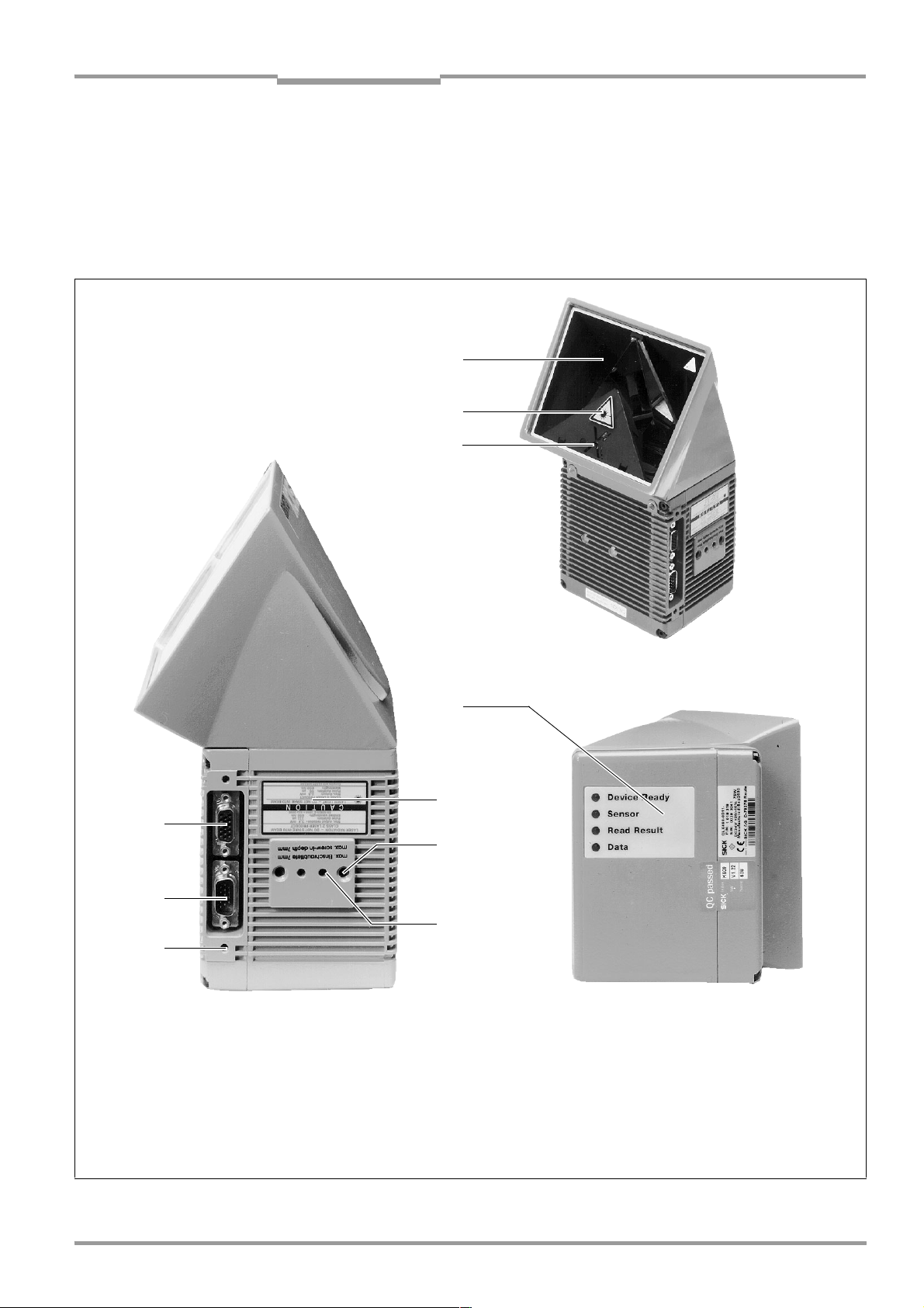
3.1.4 Design
➊
➋
➌
➑
➐
➏
Legend
➊ Reading window
➋ Laser warning label
➌ Mark for counting direction for the
reading angle
➒
➋
➍
➎
➍ Blind hole thread M6, 7 mm deep,
for securing the device
➎ Drilled hole, Ø 3.6 mm,
6 mm deep
➏ Blind hole thread M4, 10 mm deep,
for the connector cover
➐ "Host/Term" connector
15-pin D Sub HD plug
➑ "I/O" connector,
15-pin D Sub HD socket
➒ LED (status indicators)
Fig. 3-1: Design of the CLX
8009237/RB47/2007-08-03 © SICK AG · Division Auto Ident · Germany · All rights reserved 3-3
Page 22
Chapter 3 Operating Instructions
Product description
CLX490 Compact OMNI Scanner
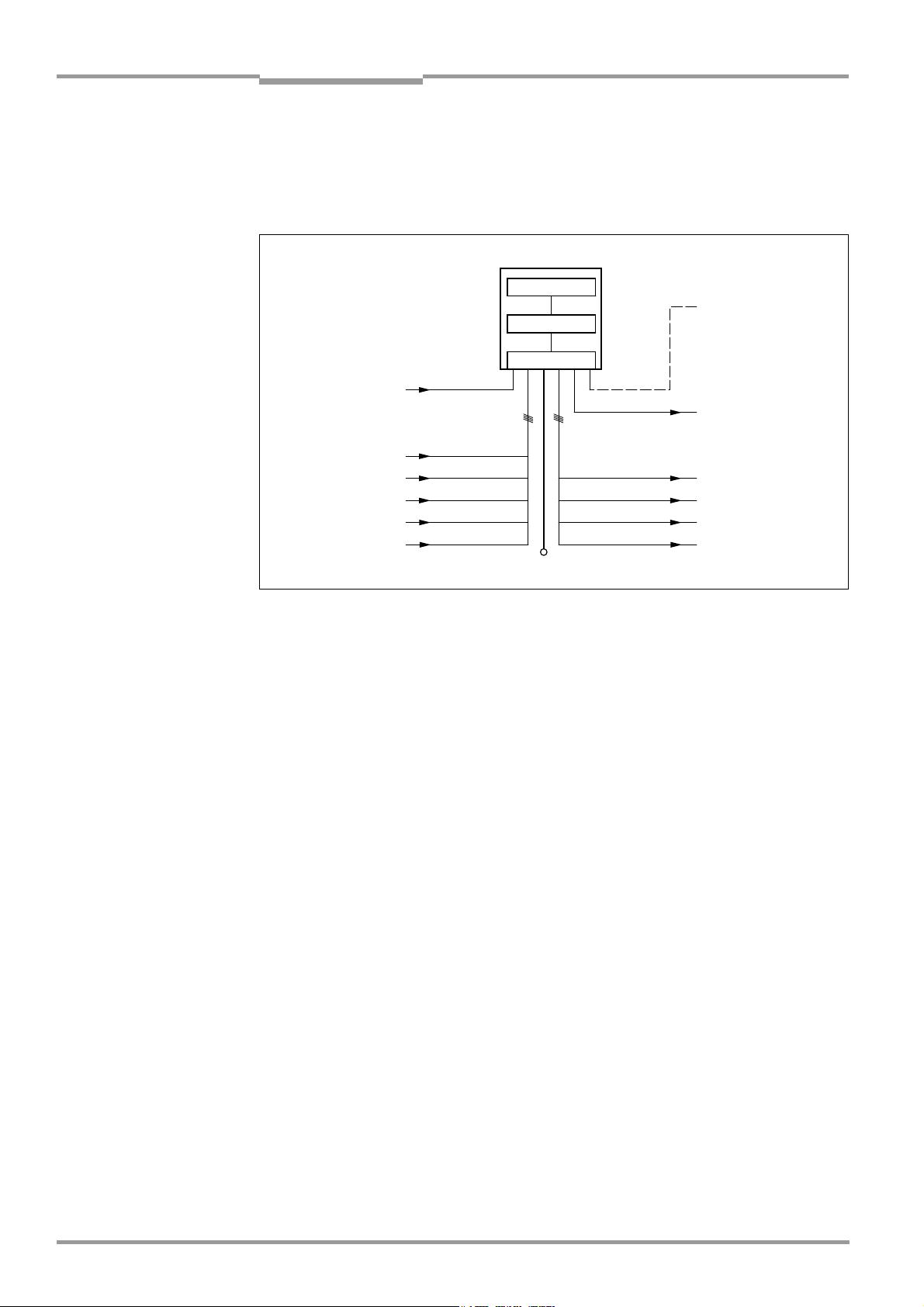
3.2 Method of operation
The CLX first scans the bar code with a folded scan line (resulting in a cross) and then decodes it. The data is forwarded via the main data interface (serial host interface) to a host/
PC for further processing. An overview of the CLX functions is provided in Fig. 3-2.
CLX490
PC
Operation
Parameterization,
etc.
HOST
Further processing
of the reading result
Status display
e. g. Device Ready
e. g. Good Read
e. g. No Read
e. g. Match 1
Photoelectric
switch
Reading pulse
1)
Signal
Focal control
Conveyer increment
1) if requered
Fig. 3-2: Block diagram: CLX functions
"Sensor"
"IN 0"
"IN 1"
"IN 2"
"IN 3"
"IN 4"
Scanner
Decoder
Interface
V
S
"Terminal"
"Host"
"Result 1"
"Result 2"
"Result 3"
"Result 4"
The CLX is equipped with two decoders:
• The SMART decoder (SICK Modular Advanced Recognition Technology) for decoding
bar codes with small code height, bar codes that are dirty or damaged, as well as bar
codes that are tilted excessively (azimuth angle)
• The tried-and-tested standard decoder of the CLV series
The CLX derives useful diagnosis data from the reading process and can transfer it also to
the host. It also records operating data that can be interrogated at any time. The quality of
the read can be checked in percentage evaluation mode.
To start the reading process when an object is located in the reading field, the CLX requires
a suitable trigger. This opens an internal time window ("reading interval") in the CLX. In the
default configuration, this trigger is supplied by an external reading pulse sensor. Alternative
trigger sources include free-running mode or a command via the host interface (for more
complex applications: OTC trigger).
With small object distances (object distance < reading gate length) the bar code has to be
allocated to the right object with the help of the internal tracking of the CLX.
The current operating status is indicated by four LEDs.
If the trigger is supplied externally, the "Sensor" switching input instructs the CLX to start the
reading process. The five "IN 0 to IN 4" switching inputs switch the focus position in
response to certain events, as an alternative to the autofocus function. The "IN 4” input can
also be assigned to special functions. The four "Result 1 to Result 4" switching outputs can
be assigned to different functions alternativly for displaying the result status and also control
external devices, such as a PLC.
The CLX is operated and configured via the auxiliary interface (serial auxiliary interface) using
the CLV-Setup software or via the host interface/auxiliary interface using command strings.
System, warning, and error messages help you configure the device and locate the source
of errors during startup and reading mode.
3-4 © SICK AG · Division Auto Ident · Germany · All rights reserved 8009237/RB47/2007-08-03
Page 23
Operating Instructions Chapter 3
CLX490
Product description
3.2.1 Autofocus function
The autofocus function enables the CLX to detect the distance of an object without the need
for external sensors, and then adjust the focus position automatically. In order to do so, the
CLX measures the object distance in its reading field in front of the reading window and internally creates a distance profile. Following this, it positions the focus on the object.
3 operating modes are provided for various applications:
• Minimum distance: the CLX focuses on the minimum distance in the distance profile
and ignores the background in the reading field. Application: with unobstructed view of
the object without any surrounding objects protruding into the reading plane.
One object with bar code(s) only is inside the reading field during one reading pulse.
• Differential background: the distance profile of the reading field background is pro-
grammed (teach-in) in the CLX without any objects present. The CLX focuses on the object which it recognizes by comparing the object with the background. Application: with
unobstructed view of the object restricted by other objects that protrude into the reading plane.
One object with barcode(s) only is inside the reading field during one reading pulse.
• Differential background and tracking: if several objects with different distances are
positioned in the reading field at the same time (distance conflict), the CLX focuses on
the object that is nearest to but has not exceed its internal focus switchover point.
Application: in OTS operation (applications with tracking by the OMNI Tracking Controller
OTC 400), or stand alone in internal tracking mode.
The distance profile of the background can also be displayed in the "CLV-Setup" program.
The reading field is defined by the autofocus range. The park setting of the focus position,
from which the device focuses for each read, can be specified in addition to a time and/or
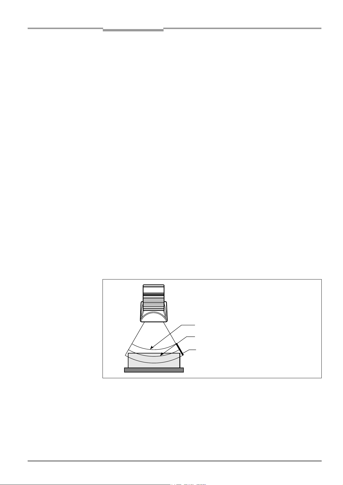
position-related delay (timeout or hysteresis). If necessary, an offset can be defined for the
focus position to be set by the measurement. The depth of field, which radiates in the direction of the scan line and is caused by the V-principle of the beam deflection, is optimized as
a result (Fig. 3-3).
Measured distance
Optimum focus position:
measured distance plus offset for maximum
Depth of field (DOF)
Fig. 3-3: Optimization the depth of field for the object
8009237/RB47/2007-08-03 © SICK AG · Division Auto Ident · Germany · All rights reserved 3-5
Page 24
Chapter 3 Operating Instructions
Product description
CLX490 Compact OMNI Scanner
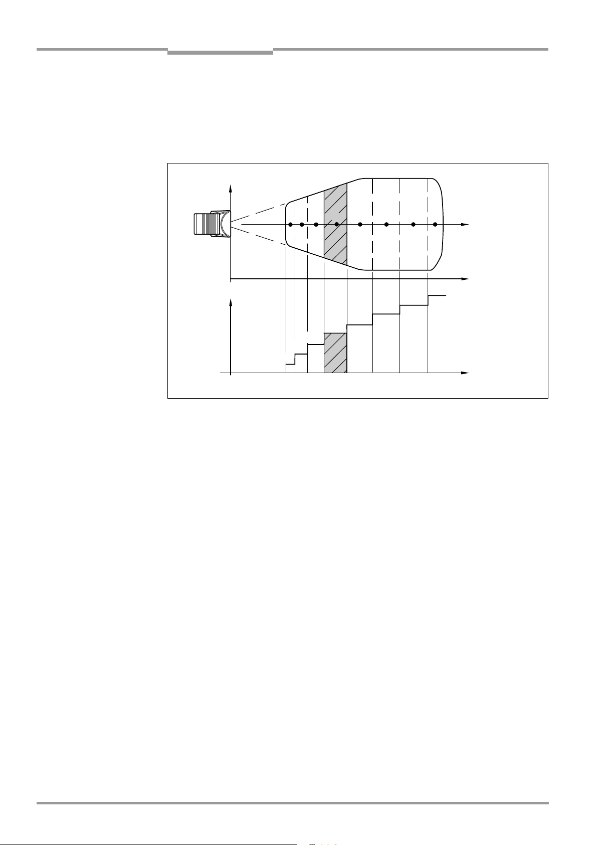
3.2.2 Event-controlled dynamic focus control
As an alternative to the autofocus function, the CLX can switch its focus position in response
to certain events and thus dynamically cover a large reading range. A maximum of eight
reading ranges can be defined as distance configurations for this purpose and approached
consecutively in reading mode (see Fig. 3-4).
Reading
field height
123 5 8
Focus
position
DC 2
DC 1
Fig. 3-4: Dynamic focus control: classification of the reading range in distance configurations
4
DC 5
DC 4
DC 3
DC = Distance Configuration
6 7
DC 6
Focus position
Reading distance
DC 8
DC 7
Reading distance
The switch over takes place in response to changes in the object distance (with reads from
above: object height detection). The trigger source for the switchover is a signal combination
at the "IN 0 to IN 4" switching inputs, a command on the host interface/auxiliary interface
or the integrated timer (e. g. for search mode). The distance configurations are assigned to
the swichover sequence by means of a programmable assignment table. The object distance measurement of the autofocus function can additionally be used to define the distance configurations.
3.2.3 Additional components
Heater
The CLX can be permanently equipped with a heater for applications involving temperatures
up to max. –30 °C (e. g. in a freezer).
The design, technical data, and power-up behavior of the CLX are described in Chapter 10.4
Optional heating, Page 10-12.
External parameter memory
The external parameter memory is located in a connector cover which, when mounted,
covers the two electrical terminals on the CLX (IP 65). The parameter memory saves you
time when a CLX is replaced locally by providing a copy of the current parameter set. In other
words, you do not have to configure the new device.
For information on applications and operating procedures, see Chapter 10.3 Installing and
operating the external parameter memory, Page 10-8.
3-6 © SICK AG · Division Auto Ident · Germany · All rights reserved 8009237/RB47/2007-08-03
Page 25
Operating Instructions Chapter 3
CLX490
Product description
3.3 Indicators and control elements
3.3.1 Control elements
The CLX is operated and configured via the auxiliary interface using the CLV-Setup program
or using command strings sent via the host interface/auxiliary interface. A variety of parameter options allow you to adapt the device to a wide range of applications.
The following can be defined:
• The configuration of the code types
• The read, evaluation, and output properties
• The communication parameters of the host interface
• The structure of the data output string for Good Read and No Read on the host interface
• The function of the auxiliary interface
Chapter 10.6 Installing and operating the "CLV-Setup" program, Page 10-15 describes the
procedure for installing the "CLV-Setup" program and explains how to use it. The parametrization (configuration) procedure is explained in Chapter 6.4 Configuring (parameterization)
the CLX, Page 6-4.
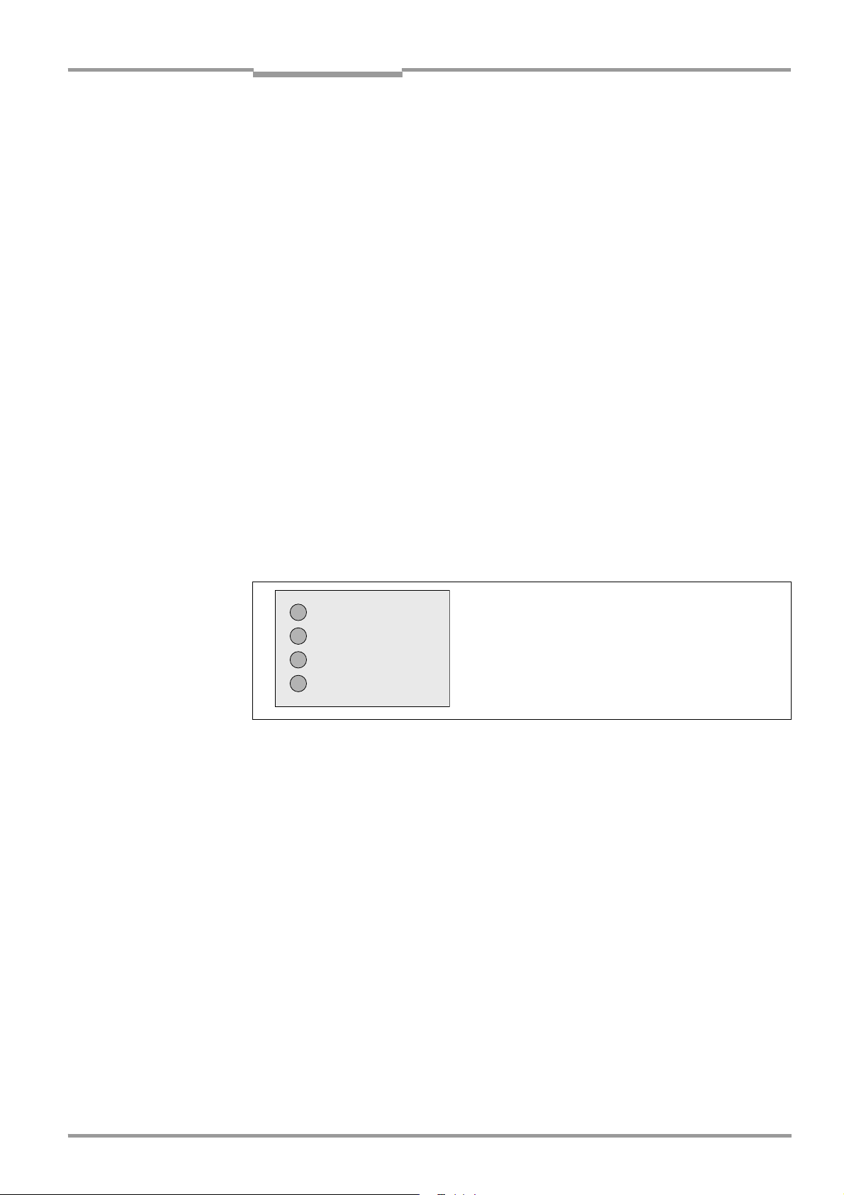
3.3.2 Function of the LEDs
Four LEDs indicate the operating status, activity of the laser diode, reading result status, and
data transfer on the host interface. The LEDs are located on the rear of the device (Fig. 3-5).
If the optional external parameter memory is connected, the LEDs also indicate whether the
memory was successfully accessed.
Device Ready
Sensor
Read Result
Data
Fig. 3-5: LEDs
The meaning of the LEDs in the various operating modes/functions is shown in Table 3-2,
Page 3-8 and Table 3-3, Page 3-9.
8009237/RB47/2007-08-03 © SICK AG · Division Auto Ident · Germany · All rights reserved 3-7
Page 26

Chapter 3 Operating Instructions
Product description
CLX490 Compact OMNI Scanner
CLX without external parameter memory
Operating mode LED Display Function
Start Device Ready Green • Lights up after power-up if the self-test was successful
Subsequent behavior depends on selected start option
Start option: START WITH EXTERNAL PARAMETERS (DEFAULT)
• Lights up constantly (CLX has loaded internal parameter set)
Start option: S
• Lights up constantly (CLX has loaded internal parameter set)
TART WITH INTERNAL PARAMETERS:
Start option: S
• Blinks constantly together with the "Read Result" LED
TART WITH COPY INTERN -> EXTERN:
1)
(CLX has loaded internal parameter set)
Read Result Green
Start option: START WITH COPY INTERN -> EXTERN:
• Blinks constantly together with the "Device Ready" LED
Reading mode Device Ready Green • Lights up constantly
• Extinguishes with new operating mode/function
Sensor Green • Lights up if reading diode is active
(The laser diode is activated/deactivated by reading pulse)
• Lights up constantly in Free-running mode, since laser diode is always active
Read Result Green LED is linked to the "Result 2" switching output and indicates the selected result
status for the defined pulse duration of the output.
• Lights up after a successful read (default: Good Read)
• Lights up if the match code comparison is active, the bar code read matches the
specified match code(s) and the corresponding result status output is selected
for the "Result 2" output
Data Yellow • Flickers when the CLX transfers data to the host on the host interface
Percentage Sensor Green • Lights up constantly, as Free-running mode is active
evaluation Read Result Green Behavior depends on the reading quality:
• Extinguishes if reading rate < 30 %
• Blinks twice a second if reading rate 30 % to 70 %
• Blinks five times a second if reading rate 70 % to 90 %
• Lights up constantly if reading rate > 90 %
1) Set the start option to START WITH THE INTERNA L PARAMETERS on the DEVICE CONFIGURATION tab in the "CLV-Setup" program. Download to CLX!
1)
Table 3-2: Meaning of LEDs: CLX without external parameter memory
3-8 © SICK AG · Division Auto Ident · Germany · All rights reserved 8009237/RB47/2007-08-03
Page 27

Operating Instructions Chapter 3
Product description
CLX490
CLX with external parameter memory connected
Operating mode LED Display Function
Start Device Ready Green • Lights up after power-up if the self-test was successful
Subsequent behavior depends on selected start option:
Start option: S
• Blinks for approx. 10 s before lighting up constantly
(CLX has loaded the parameter set from the external parameter
memory and starts reading mode straight away)
• Blinks for approx. 10 s together with the "Read Result" LED, then lights up
constantly.
(CLX has loaded the parameter set from the external parameter memory with
tolerated errors
• Lights up constantly
(CLX could not find an external parameter memory and loads the internal parameter set instead)
• Blinks constantly together with the "Read Result" LED
(The external parameter memory contains the parameter set for another CLX type,
or is corrupt.)
CLX has loaded the internal parameter set. It starts Reading mode but does not
output data over the host interface)
Start option: S
• Lights up constantly (CLX has loaded internal parameter set)
TART WITH EXTERNAL PARAMETERS (default):
1)
and starts reading mode straight away)
2)
TART WITH INTERNAL PARAMETERS:
Start option: S
TART WITH COPY INTERN -> EXTERN:
• Blinks alternately with the "Read Result" LED for approx. 10 s before lighting
up constantly
(CLX has successfully copied the internal parameter set to the external memory
and has reset the start option to S
TART WITH EXTERNAL PARAMETERS)
CLX has loaded the internal parameter set.
• Blinks constantly together with the "Read Result" LED
2)
(The external parameter memory is either not connected or corrupt, or the
parameter set is too large to be copied).
CLX has loaded the internal parameter set.
Read Result Green Start option: S
• Blinks for approx. 10 s together with "Device Ready" LED
• Blinks constantly together with the "Device Ready" LED
TART WITH EXTERNAL PARAMETERS (Default):
1)
(see above) or
2)
(see above)
Start option: START WITH COPY INTERN -> EXTERN:
• Blinks alternately with "Device Ready" LED for approx. 10 s (see above) or
• Blinks constantly together with the "Device Ready" LED
2)
(see above)
Reading mode Device Ready Green • Lights up constantly
• Extinguishes with new operating mode/function
Sensor Green • Lights up if reading diode active.
(The laser diode is activated/deactivated by the reading pulse)
• Lights up constantly in Free-running mode, since the laser diode is constantly
active
Read Result Green LED is linked to the "Result 2" output and indicates the selected result status for the
defined pulse duration of the output.
• Lights up after a successful read (default: Good Read)
• Lights up if the match code comparison is active, the bar code read matches the
specified match code(s) and the corresponding result output is selected for the
"Result 2" output
1) We recommend that you check the parameter set manually, e. g. by printing out the entire configuration. For troubleshooting, see also Chapter 8.3.2 LED error messages
for the external parameter memory, Page 8-3
2) Stops blinking when you switch from Reading mode to Parameterization mode
Table 3-3: Meaning of LEDs: CLX with external parameter memory
8009237/RB47/2007-08-03 © SICK AG · Division Auto Ident · Germany · All rights reserved 3-9
Page 28

Chapter 3 Operating Instructions
Operating mode LED Display Function
Product description
CLX490 Compact OMNI Scanner
Reading mode
(contd.)
Percentage Sensor Green • Lights up constantly, since Free-running mode is active
evaluation Read Result Green Behavior dependent on the reading quality:
Table 3-3: Meaning of LEDs: CLX with external parameter memory (contd.)
Data Yellow • Flickers when the CLX transmits data to the host over the host interface
• Extinguishes if reading rate < 30 %
• Blinks twice a second if reading rate 30 % to 70 %
• Blinks five times a second if reading rate 70 % to 90 %
• Lights up constantly if reading rate > 90 %
3-10 © SICK AG · Division Auto Ident · Germany · All rights reserved 8009237/RB47/2007-08-03
Page 29

Operating Instructions Chapter 4
CLX490
Installation
4 Installation
4.1 Installation sequence
• Change the language version of the laser warning label (if necessary)
• Select the mounting location for the CLX
• Align the CLX with the bar code and mount the CLX
• Mount the AMV/S60 Connection Module
• Connect the CLX to the AMV/S60 Connection Module
• Adjust the CLX so that it is in line with the bar code
• Mount the reading pulse sensor for external triggering the reading pulse
• Optionally: Mount incremental transmitter (for the internal tracking mode)
• Option with event-controlled dynamic focus control:
mount the sensors for detecting the object distance
Note Don’t open the device. The warranty will be forfeited if the device is opened.
4.2 Preparations
4.2.1 Required components
• CLX490 Compact OMNI Scanner
4.2.2 Required accessories
• SICK mounting bracket for the CLX:
depending on the order, angle bracket no. 2022996, or quick-clamping device
no. 2016110 with securing material for the CLX
– or –
Alternatively, if the bracket is supplied by the user:
– Stable mounting device that allows the alignment of the CLX to be varied in the x and y
axes. The weight of the CLX is approx. 2 kg.
– 2 screws M6 for the CLX. The screw length depends on the wall thickness of the
bracket used. Depth of engagement in CLX max. 7 mm from housing surface.
• AMV/S60 Connection Module (not included in the scope of supply of the CLX)
• Reading pulse sensor for external reading pulse triggering, e. g. photoelectric reflex
switch/ photoelectric proximity switch (not included in the scope of supply of the CLX)
• Option with event-controlled dynamic focus control: sensors for detecting the object
distance, e. g. photoelectric reflex switches/photoelectric proximity switches (not
included in the scope of supply of the CLX)
4.2.3 Required auxiliary parts
• 2 screws M6 for securing the SICK mounting bracket to the base. The screw length
depends on the wall thickness of the base.
• Set of laser warning labels (if necessary)
• Tool
• Measuring tape (up to 2,000 mm)
• Protractor
8009237/RB47/2007-08-03 © SICK AG · Division Auto Ident · Germany · All rights reserved 4-1
Page 30
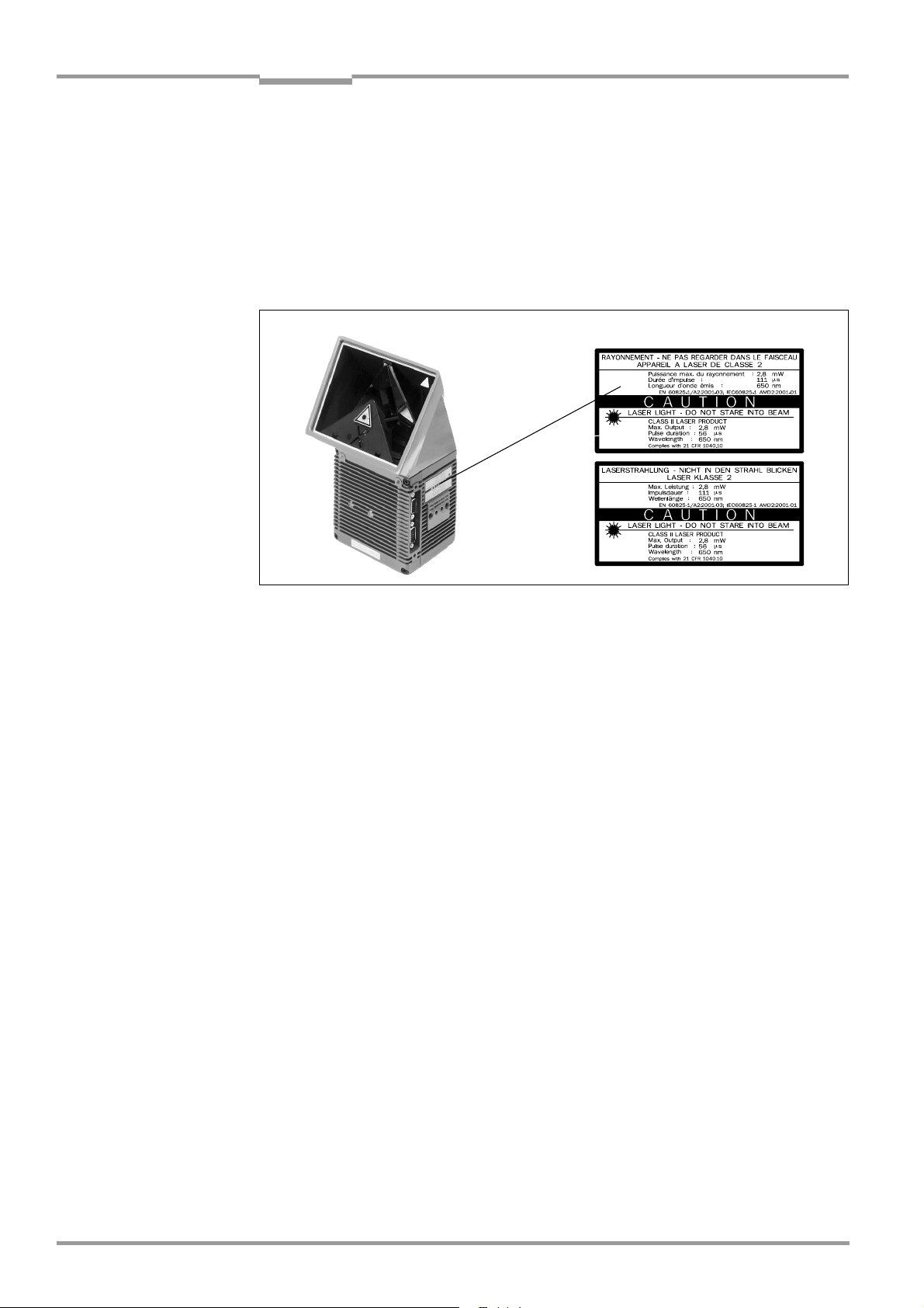
Chapter 4 Operating Instructions
Installation
CLX490 Compact OMNI Scanner
4.2.4 Replacing the laser warning label
If necessary, replace the GB English/US English laser warning label with the required language (Fig. 4-1).
The device is delivered with a set of laser warnings in:
• German/US English laser warning and
• French/US English laser warning
See also Chapter 2.3 General safety instructions and protection measures, Page 2-2.
Supplied laser warnings:
Fig. 4-1: Replacing the laser warning labels
4.2.5 Selecting the mounting location
When you select the mounting location, the distance between the CLX and the host and
between the CLX and the bar code are important.
Distance between the CLX and the host
The CLX can be mounted at a maximum distance of 1,200 m from the host without a
connection to the SICK network or a bus. In practice, however, the distance depends on the
physical configuration of the host interface and the data transfer rate (see Table 5-7,
Page 5-8).
Distance between the CLX and the AMV/S60 Connection Module
The AMV/S60 Connection Module should not be located further than 10 m from the CLX,
since the "CLV-Setup" program on the PC accesses the auxiliary interface (RS 232) of the
CLX via this module.
4-2 © SICK AG · Division Auto Ident · Germany · All rights reserved 8009237/RB47/2007-08-03
Page 31

Operating Instructions Chapter 4
CLX490
Installation
4.2.6 Mounting accessories
The CLX is secured in position using the two tapped blind holes (M6) above the electrial connections. Fig. 4-2 shows the location of the threads near the CLX.
The dimensions of the CLX housing are shown in Fig. 9-1, Page 9-2.
175.5
114.7
33.5
78
113
Fig. 4-2: Position of the securing threads on the CLX
21
56
43.2
12
38.5
10
10
10
Drilled hole,
∅ 3.6, 6 mm deep
Blind hole thread,
M6, 7 mm deep
The CLX can be mounted using the SICK bracket:
• Angle bracket no 2022996.
• Quick-clamping device no. 2016110
The brackets are designed to support the mounting of the CLX to horizontal and vertical surface. Fig. 4-3 shows two mounting examples for angle bracket no. 2022996.
Fig. 4-3: Mounting possibilities of the CLX with angle bracket no. 2022996
The dimensions of the angle bracket is shown in Chapter 10.13 Dimensioned drawings of
the accessories, Page 10-39.
8009237/RB47/2007-08-03 © SICK AG · Division Auto Ident · Germany · All rights reserved 4-3
Page 32

Chapter 4 Operating Instructions
Installation
CLX490 Compact OMNI Scanner
4.2.7 Distance between the CLX and the object
Basic alignment between the CLX and bar code
The CLX is used for reading omnidirectionally oriented bar codes on the lateral or upper
sides of objects. Fig. 4-4 shows the basic alignment of the CLX.
Reading distance to the object
The distance between the reading window of the CLX and the object must not exceed the
technical limits. The height of the reading field is shown as a function of the reading distance
for various resolutions (module widths) in Chapter 10.2.2 Reading performance data
CLX490 Compact OMNI Scanner, Page 10-2.
Fig. 4-4 shows the definition of the reading distance "a" (radial measured) from the reading
window.
Reading distance a
Fig. 4-4: Definition of the reading distance a to bar code and convoyer direction
Due to the X-principle of beam deflection, the reading field height (for evaluating the useful
length of the scan line) depends on the readling distance.
Angular alignment of the CLX
All possible reading angles that can occur between the scan line and the bar code must be
taken into consideration (Fig. 4-5 and Table 4-1).
α :Azimuth angle (tilt)
Reading
range
Object
distance
Fig. 4-5: Reading angles between the scan line and the bar code
β: Angle of inclination (pitch)
γ: Angle of rotation (skew)
Angle Limit value
Tilt α (azimuth) Omnidirectional
Pitch β Max. 45°
Skew γ Max. 45°
Table 4-1: Permissible reading angles between the scan lines and bar code
4-4 © SICK AG · Division Auto Ident · Germany · All rights reserved 8009237/RB47/2007-08-03
Page 33
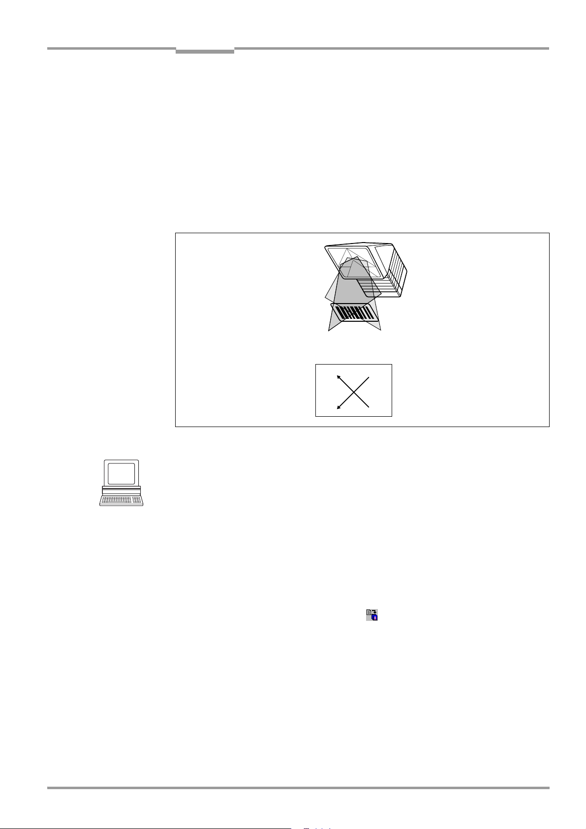
Operating Instructions Chapter 4
CLX490
Installation
Note If reading from the front, mount the CLX above the conveyor belt in such a way against the
conveying direction that the scan line hits the object under a skew of approx. 10°.
4.2.8 Count direction of the reading angle RA
Explanation The CLX can scan and decode several bar codes with each read. In doing so, it determines
the specific local reading diagnosis data for each bar code the reading angle (RA value) of
the center of the bar code within the scan.
Fig. 4-6 shows the count direction of the reading angle. The count direction of the reading
angle is marked by a cross in the reading window.
By determining this data, the device can separate identical bar codes.
Tip
100 0
50
Fig. 4-6: Count direction of the reading angle RA in the scan line
51
0100
In the default setting, the CLX does not output the "RA" value in the reading result on the
host interface. If this is required to evaluate the result in the host, the values can be included
in the "Code-Info/Separator" block of the output string using the "CLV-Setup" program.
Configuring the Code-Info/Separator:
1. Choose the D
2. Click the C
DIT PARAMETER TFS dialog box is displayed.
The E
ATA STRINGS tab.
ODE-INFO/SEPARATOR field.
3. In the list field, click the RA parameter.
RA then appears in the top line.
4. Confirm your selections with OK.
5. Download the data to the CLX by clicking in the toolbar.
OWNLOAD PARAMETERS dialog box is then displayed.
The D
6. The CLX490 outputs the RA value on the host interface for each bar code in the reading
result. The values are displayed as a 3-digit number in the associated "Code-Info/Separator" block.
8009237/RB47/2007-08-03 © SICK AG · Division Auto Ident · Germany · All rights reserved 4-5
Page 34

Chapter 4 Operating Instructions
Installation
CLX490 Compact OMNI Scanner
4.3 Mounting and adjusting the device
4.3.1 Mounting the CLX
1. Prepare the base for mounting the bracket as described in Chapter 4.2.2 Required
accessories, Page 4-1.
2. Place the object containing the bar code within the reading field of the CLX (in the
position at which it is to be read) with the conveyor belt switched off.
3. Allign the CLX reading window in parallel to bar code surface. Consider the positioning
of the CLX in relation to the conveyor direction (see Fig. 4-4, Page 4-4).
All of the possible reading angles must be taken into consideration (see Fig. 4-5,
Page 4-4).
4. If it is relevant for the evaluation, note the count direction of the reading angle (see
Fig. 4-6, Page 4-5).
5. Mount the CLX bracket on the base.
Risk of damage to the device!
The maximum depth of engagement of the two blind hole threads M6 is 7 mm.
Longer screws will damage the device.
¾ Use screws with the correct length.
6. Screw the screws M6 through the bracket into the blind hole threads of the CLX.
7. Tighten the screws slightly.
8. Adjust the CLX as described below.
4.3.2 Adjusting the CLX
The CLX can be adjusted in Percentage Evaluation mode. In this mode, the CLX displays the
quality of the bar code reads that enter the CLX reading field statically (the object is not
moved on the conveyor belt). In the Free-running mode the CLX performs 100 scans and
evaluates the reading quality statistically. It then outputs the reading results every 2 s on the
auxiliary interface.
Note In default setting, the CLX operates in the autofocus mode "Minimum distance“. As a result,
the CLX focuses on the object that is nearest in Percentage Evaluation mode. The view on
the object with the scan line must be unobstructed, i. e. any other objects must not protude
into the autofocus space. If they do so, the autofocus mode "Differential background“ must
be selected. Alternatively a fixed focus position can be set.
The behavior of the "Read Result" LED also indicates the reading quality.
– The LED is extinguished if reading quality is < 30 %
– The LED flashes twice per second if the reading quality is 30 % to 70 %
– The LED flashes five times per second if the reading quality is 70 % to 90 %
– The LED is lit continuously if the reading quality is > 90 %
The scanning frequency in the default setting is 800 Hz.
1. Connect the CLX to the AMV/S60 Connection Module and switch on the power supply
(see Chapter 5.5.3 Connecting the supply voltage, Page 5-13).
After it has started, the CLX confirms that the self-test was successfuly and switches to
reading mode ("Device Ready" LED lights up).
4-6 © SICK AG · Division Auto Ident · Germany · All rights reserved 8009237/RB47/2007-08-03
Page 35

Operating Instructions Chapter 4
CLX490
Installation
2. Connect the PC to the auxiliary interface of CLX. To do so, connect a 3-core RS 232
data cable (null modem cable) to the internal 9-pin "Service" plug of the AMV/S60 (see
Chapter 5.5.6 Connecting the PC, Page 5-15).
3. Start Windows and the "CLV-Setup" program (see Chapter 10.6.3 Starting CLV-Setup,
Page 10-18).
Choosing the standard decoder:
4. Choose the C
5. Click the S
ODE CONFIGURATION tab.
TANDARD option in the DECODER section.
6. Download the settings to the CLX.
To do so, click the S
OWNLOAD PARAMETER in the context menu.
D
TANDARD option again with the right mouse button and choose
CLV-Setup copies the parameter to the CLX temporarily.
The CLX then operates with the standard decoder (until the CLX is switched off).
Activating Percentage Evaluation mode:
7. From the V
IEW menu, choose PERCENTAGE EVALUATION.
The dialog box for entering the distance configuration appears.
8. Click the relevant distance configuration for the reading distance:
– with autofocus mode the distance configuration no. 1
– with event-controlled dynamic focus control the distance configuration that matches
the reading distance of the object (default: no. 1, focus position F = 1,200 mm).
9. Confirm the dialog box with OK.
The Terminal Emulator is launched and displays the reading result continuously (see
Chapter 6.5.2 Percentage evaluation, Page 6-17).
Monitor the reading quality (%) during each of the subsequent steps!
Fine adjustment:
10. Align the CLX in such a way that the angle between the scan line and the bars on the
bar code CLX is almost 90°.
11. To avoid interfering reflections, align the CLX reading window in parallel to the bar code
surface. Consider the positioning of the CLX in relation to the convoyer direction (see
Fig. 4-4, Page 4-4).
12. If necessary, align the intersecting point of folded scanline exactly with the bar code.
13. Move objects carrying bar codes into the CLX reading field manually under realistic
conditions and check the reading result. If the objects are aligned randomly, or if the bar
code is located at different positions (angles), ensure that the limit values of the
permissible reading angles are not exceeded.
14. Adjust the CLX in such a way that the good read rate is between 70 to 100 %.
With event-controlled dynamic focus control, for each defined reading range (distance
configuration), check the selected focus position and correct the parameter settings if
necessary (see Chapter 6.4.3 Guide to parameterization menu, Page 6-8).
15. Tighten the screws on the CLX.
The CLX is aligned with the bar code.
8009237/RB47/2007-08-03 © SICK AG · Division Auto Ident · Germany · All rights reserved 4-7
Page 36

Chapter 4 Operating Instructions
Installation
CLX490 Compact OMNI Scanner
4.4 Mounting the external components
4.4.1 Mounting the AMV/S60 Connection Module
1. Mount the AMV/S60 Connection Module near the CLX.
The distance between the AMV/S60 and CLX should not exceed max. 10 m.
2. Mount the AMV/S60 in such a way that accessed to the open device is always possible.
The auxiliary interface of the CLX is accessed via the internal "Service" plug.
Detailed information on the mounting and electrical installation procedures is provided in the
Operating Instructions for the "AMV/S60 Connection Module" (order no. 8008296).
4.4.2 Mounting the external reading pulse sensor
If the CLX is triggered by an external reading pulse sensor, the sensor must be mounted in
the vicinity of the CLX. The "Sensor" switching input is selected as the default trigger source
for this trigger type. The default debounce time of the input is 30 ms.
Depending on the application, you may need to mount the sensor in such a way that bar
codes on objects of different sizes can be read completely during the reading interval. The
exact position fo the external sensor in relation to the scanner can be seen in Fig. 10-3 to
Fig. 10-5 onwards page 10-4.
Note In default setting, the CLX operates in the autofocus mode "Minimum distance“. As a result,
the CLX focuses on the object that is nearest. The view on the object with the scan line must
be unobstructed, i. e. any other objects must not protude into the autofocus space. If they
do so, the autofocus mode "Differential background“ must be selected. Alternatively a fixed
focus position can be set.
1. Mount the reading pulse sensor.
2. Connect the reading pulse sensor to the "Sensor" switching input of the CLX via the
AMV/S60 Connection Module (see Chapter 5.5.7 Connecting the switching inputs,
Page 5-16).
3. Connect the CLX to the AMV/S60 Connection Module and switch on the power supply
to the module (see Chapter 5.5.3 Connecting the supply voltage, Page 5-13).
After it has started, the CLX confirms that the self-test was successfull and switches to
Reading mode ("Device Ready" LED lights up).
4. Connect the PC to the auxiliary interface of CLX. To do so, connect a 3-core RS 232
data cable (null modem cable) to the internal 9-pin "Service" plug of the AMV/S60 (see
Chapter 5.5.6 Connecting the PC, Page 5-15).
5. Start Windows and the "CLV-Setup" program (see Chapter 10.6.3 Starting CLV-Setup,
Page 10-18).
6. From the VIEW menu, choose READING MODE.
The Terminal Emulator is launched. The CLX is in Reading mode (default: SMART/
Standard Decoder).
Monitor the reading result during each of the subsequent steps!
7. Move objects with bar codes into the CLX reading field manually under realistic conditions and check whether the reading result and trigger pulse are correct.
8. Repeat the procedure with the conveyor switched on. Check whether the reading
procedure is synchronized with the objects.
4-8 © SICK AG · Division Auto Ident · Germany · All rights reserved 8009237/RB47/2007-08-03
Page 37

Operating Instructions Chapter 4
CLX490
Installation
Parameterizing an external sensor as a trigger source:
These settings are not required if the CLX is operated with the default configuration.
1. Choose the DEVICE CONFIGURATION tab.
2. In the section R
EADING TRIGGER SOURCE click the option SENSOR INPUT (ACTIV HIGH).
3. Download the settings to the CLX by clicking in the toolbar.
The D
OWNLOAD PARAMETERS dialog box is then displayed.
4. Confirm the dialog box by choosing P
ERMANENT.
The CLX operates with the "Sensor" switching input as an external trigger source. The
reading pulse starts when the input is energized (high).
4.4.3 Mounting the sensors for detecting the object distance
If the dynamic focus control function of the CLX is triggered by external sensors, suitable
sensors must be mounted in the vicinity of the CLX. Fig. 4-7 shows an example of a read
operation from above. The sensors must be arranged in such a way that all of the potential
object heights are classified uniquely and overlapping reading ranges occur that can be
formed with the depths of field of the CLX. A maximum of five switching inputs are available
for this purpose. A max. of 32 switching states for 8 distance configurations (reading ranges)
can be implemented using the internal assignment table (combinations). Photoelectric reflex
switches, for example, can be used to detect the object distance. In the default setting, all
five "IN 0 to IN 4" switching inputs are selected for dynamic focus control.
Object distance
DC 8
Reading distance
DC 2
DC 1
DC = Distance Configuration
Fig. 4-7: Mounting example for object distance detection
h7
LS7
h2
LS2
h1
LS1
1. The depths of field of the CLX for the bar code resolution in question is shown in the
graph in Chapter 10.2.2 Reading performance data CLX490 Compact OMNI Scanner,
Page 10-2. Find and note suitable focus positions for overlapping reading ranges.
2. Mount distance sensors (e. g. photoelectric reflex switches) one above the other in a
row at the mounting location to measure the object distance (see also assignment
Table 5-20, Page 5-18). It is advisable to mount these distance sensors opposite the
direction of motion of the conveyor belt at approx. 100 mm in front of the reading pulse
sensor.
8009237/RB47/2007-08-03 © SICK AG · Division Auto Ident · Germany · All rights reserved 4-9
Page 38

Chapter 4 Operating Instructions
Installation
CLX490 Compact OMNI Scanner
3. Connect the distance sensors to the "IN 0 to IN 4" switching inputs on the CLX via the
AMV/S60 Connection Module (see Chapter 5.5.7 Connecting the switching inputs,
Page 5-16).
4. Set the focus positions for the required reading ranges on the READING CONFIGURATION
tab in the CLV-Setup program. To do so, choose the I
down list of the F
5. Click the D
OCUS CONTROL section.
ISTANCE CONFIGURATION button and edit the required entries in the dialog box
NPUTS/SERIAL option in the drop
that is then displayed (default: Focus position F 1 up to F 8 = 1,200 mm).
6. As described in Chapter 4.3.2 Adjusting the CLX, Page 4-6, choose the standard decoder.
7. Perform a temporarily download to the CLX.
8. Start Percentage Evaluation mode
9. Check the reading quality in all distance configurations while the conveyor bel stationary.
10. Then check the distance detection function in Reading mode under realistic conditions.
To do so, monitor the reading result in the Terminal Emulator as described in
Chapter 4.4.2 Mounting the external reading pulse sensor, Page 4-8.
11. If the distance detection function operates correctly, reset the decoder to the SMART/
S
TANDARD option and perform a permanently download to the CLX.
Note The CLX can switch between a maximum of 8 distance ranges for slow search runs using
the integrated timer reversal points. The CLX can be switched between a maximum of 8 distance ranges synchronously to the reading process using command strings.
4.5 Dismantling the device
1. Switch off the power supply to the AMV/S60 Connection Module.
2. Undo the screws for the cable connections on the CLX and disconnect the cables.
With mounted external parameter memory (in connector cover)(optional):
Undo both screws and remove the cover.
3. Unscrew the CLX from the mounting device.
When removing the device from service for the last time, please dispose of it in an
environmentally-friendly manner, as described in Chapter 7.4 Disposal, Page 7-3.
4-10 © SICK AG · Division Auto Ident · Germany · All rights reserved 8009237/RB47/2007-08-03
Page 39

Operating Instructions Chapter 5
CLX490
Electrical installation
5 Electrical installation
5.1 Installation sequence
• Connect the CLX to a SICK Connection Module from the series AMV/S, BMV/BMH10
or BMS20, or using a customer-specific wiring configuration
• Connect the data and function interfaces of the CLX in the module
• Connect the PC to the Connection Module (at the auxiliary interface on the CLX)
• Connect the power supply to the Connection Module
5.1.1 SICK Connection Modules (overview)
CLX Type Temperature
range
CLX without heater 0 to +40 °C AMV60 – Connecting one CLX
CLX with heater –30 to +35 °C AMV100 – Connecting one CLX
Connection
module
AMS60 – Connecting one CLX
AMV100 – Connecting one CLX
BMV/BMH10
Profibus-DP
BMS20
Interbus-S
AMV30-071 – Connecting two CLX
AMV200 – Connecting two CLX
AMV200 – Connecting two CLX
Purpose see
– Operating voltage 18 to 30 V DC
– Enclosure rating IP 30, max. IP 54
– Operating voltage 230 V AC (115 V)/24 V DC
– Enclosure rating IP 30, max. IP 54
– Operating voltage 18 to 30 V DC
– Enclosure rating IP 52,
with connector cover max. IP 65
– Connecting one CLX to the Profibus-DP
– Operating voltage 20 to 30 V DC
– Enclosure rating IP 52,
with connector cover max. IP 65
– Connecting one CLX to the Interbus-S
– Operating voltage 24 V DC
– Enclosure rating max. IP 54
– Operating voltage 18 to 30 V DC
– Enclosure rating IP 30, max. IP 54
– Operating voltage 18 to 30 V DC
– Enclosure rating IP 52,
with connector cover max. IP 65
– Operating voltage 24 V DC +20%/–10%
– Enclosure rating IP 52,
with connector cover max. IP 65
– Operating voltage 24 V DC +20%/–10%
– Enclosure rating IP 52,
with connector cover max. IP 65
chapter
5.2.3
5.2.3
5.2.3
5.2.4
5.2.4
5.2.3
5.2.3
5.2.5
5.2.3
Table 5-1: Connection Modules for the CLX
8009237/RB47/2007-08-03 © SICK AG · Division Auto Ident · Germany · All rights reserved 5-1
Page 40

Chapter 5 Operating Instructions
Electrical installation
CLX490 Compact OMNI Scanner
5.2 Electrical connections and cables
The electrical connections on the CLX consist of two 15-pin D Sub HD connections on the
housing, one plug, and one socket.
These connections are used to route the following interfaces:
• Three serial data interfaces (host interface, CAN interface 1 and 2 as well as auxiliary
interface)
• Six switching inputs (external reading pulse and multifunctional inputs)
• Four switching outputs (for result status function, for connecting to a PLC for example)
• Power supply
5.2.1 Wire cross-sections
CLX without heater:
¾ All connections must be wired with copper cables with a minimum wire diameter of
2
0.15 mm
CLX with heater:
¾ Connect the power supply terminals (Pin 1/Pin 5) using copper wires with a minimum
cross-section of 0.75 mm
!
2
at a maximum length of 10 m!
CLX Type Temperature
range
CLX without
heater
CLX with
heater
0 to +40 °C AMV/S60 2 x No. 2020302 or
– 30 to +35 °C AMV100 1 x No. 2021298 or
5.2.2 Prefabricated cables (overview)
Connection
module
BMV/BMH10
Profibus-DP
AMV30-071 2 x No. 2020302 or
BMS20
Interbus-S
Non-SICK Power
pack
AMV200 2 x No. 2021298 or
Non-SICK
Power pack
Optional
cables
1 x No. 2020307
1 x No. 2020307 or
1 x No. 2021298
1 x No. 2020307
1 x No. 2020264 +
1 x No. 2020265 or
1 x No. 2020308
1 x No. 2020303 +
1 x No. 2020264 or
1 x No. 2020981 or
1 x No. 2021267
1 x No. 2021689
2 x No. 2021689
1 x No. 2021267 3 m Connector cover with 2 cables (open ends)
Length Type
3 m
3 m
3 m
3 m
3 m
3 m
3 m
3m
3m
3 m
3 m
3 m
3 m
3 m
3 m
3 m
3 m
Connecting cable (plug/socket)
Ext. parameter memory with 2 cables (plug/socket)
Ext. parameter memory with 2 cables (plug/socket)
Connector cover to connector cover
Connecting cable (plug/socket)
Ext. parameter memory with 2 cables (plug/socket)
Connecting cable with plug/open end
Connecting cable with plug/socket
Ext. parameter memory with 2 cables (plug/open
end)
Connecting cable with socket/open end
Connecting cable with plug/open end
Ext. parameter memory with 2 cables (open ends)
Connector cover with 2 cables (open ends)
Connector cover to connector cover
Ext. parameter memory to connector cover
Connector cover to connector cover
Ext. parameter memory to connector cover
Table 5-2: Cables for connecting the CLX
For technical data on the cables, see Chapter 10.12.5 Cables, external parameter memo-
ries and plug cover, Page 10-37.
5-2 © SICK AG · Division Auto Ident · Germany · All rights reserved 8009237/RB47/2007-08-03
Page 41

Operating Instructions Chapter 5
CLX490
Electrical installation
5.2.3 Connections/cables for the AMV/S Connection Module
The AMV/S Connection Module is suitable for connecting the CLX to peripherals (distribution
function) and the power supply. The module can be used to establish a connection to the
host (point-to-point) or integrate the device in a SICK network or daisy-chain configuration
(pass-through or master/slave configuration). The module is available in several variants
(see Table 5-1, Page 5-1).
Fig. 5-1 shows the connection principle of the AMV/S60 for one CLX.
CLX490
Scanner
Decoder
Photoelectric
switch
Reading pulse
Photoelectric
switch
Focal position
Conveyor increment
Reading pulse end
– – Cable if required
Fig. 5-1: Block diagram: Connection of the CLX to the AMV/S60 connection module
Interface
"Terminal"
"Host"
"Result 1 ... 4"
"Sensor"
"In 0 ... 4"
DC 18 ... 30 V
"Sensor"
"In 0 ... 4"
AMV/AMS60
connection module
Connecting the CLX to the AMV/S
Two cables no. 2020302 are required to connect the CLX to the AMV/S. Alternatively, the
device can be connected via the external parameter memory no. 2020307.
See Chapter 5.2.5 Connections/cables for the external parameter memory (connection to
AMV/S or BMV10/BMS20), Page 5-4.
PC
"Terminal"
HOST/PLC
"Host"
"Result 1 ... 4"
18 to 30 V DC (AMV60-011)
230 V AC 50 Hz (AMS60-013)
115 V AC 50/60 Hz (AMS60-012)
PLC
a) CLX without heater:
Connection modules: AMV/S60 and AMV30-071.
The cables no. 2020302 can be extended to 10 m (auxiliary interface: RS 232!).
b) CLX with heater:
Connection modules: AMV100 and AMV200.
The cables no. 2020302 must not be extended!
If longer cables are required, the entire power supply system (Pin 1/Pin 5) must be
2
connected with a wire cross-section of at least 0.75 mm
with a maximum length of 10 m.
Recommendation Use the cable no. 2021298 (with two connector covers, length 3 m).
The procedures for connecting and configuring the AMV/S Connection Modules are
described in the following documentation:
• Operating Instructions for the "AMV/S60 Connection Module" (no. 8008296)
• Operating Instructions for the "AMV30-071 Connection Module" (no. 8008648)
• Operating Instructions for the "AMV100/200 Connection Module" (no. 8008879)
8009237/RB47/2007-08-03 © SICK AG · Division Auto Ident · Germany · All rights reserved 5-3
Page 42

Chapter 5 Operating Instructions
Electrical installation
CLX490 Compact OMNI Scanner
5.2.4 Connections/cables for the Bus Connection Modules
BMV10 and BMS20
The BMV10 Bus Connection Module (depending on the model) is used to connect a CLX to
the Profibus-DP or to the DeviceNet for use in industrial applications. The BMS20 Bus Connection Module enables the CLX to be integrated in the Interbus-S.
Connecting the CLX to the BMV10/BMS20
BMV10: two cables no. 2020302 are required.
BMS20: the cables no. 2020265 and no. 2020264 are required.
Alternatively, via external parameter memory no. 2020307 (see Chapter 5.2.5 Connec-
tions/cables for the external parameter memory (connection to AMV/S or BMV10/
BMS20)).
a) CLX without heater:
Connection modules: BMV 10and BMS20.
The cables no. 2020302 can be extended to 10 m for CLX without a heater (host and auxiliary interface: RS-232!).
b) CLX with heater:
Connection module: BMV10.
The BMV10 may only be used if it is mounted outside the refrigeration area (temperature
range 0 to +40 °C).
The cables no. 2020302 must not be extended. If longer cables are required, the entire
power supply system (Pin 1/Pin 5) must be connected with a wire cross-section of at least
0.75 mm
2
at a maximum of 10 m.
Recommendation Use the cable no. 2021298 (with two connector covers, length 3 m).
The BMS 20 is not suitable for powering CLX with heater!
The procedures for connecting and configuring the Bus Connection Modules are described
in the following documentation:
• Operating Instructions for the "BMV/BMH10 Bus Connection Module for Profibus DP"
(no. 8008825)
• Operating Instructions for the "BMV/BMH10 Bus Connection Module for DeviceNet"
(no. 8008972)
• Technical Information for the "BMS20 Bus Connection Module for Interbus-S"
(no. 8007546)
5.2.5 Connections/cables for the external parameter memory
(connection to AMV/S or BMV10/BMS20)
The external parameter memory (external accessory) is located in a connector cover with
15-pin D Sub HD plug connections. The cover covers the terminals on the CLX so that the
enclosure rating IP 65 is achieved.
The connector cover with the external parameter memory is prefabricated with two cables,
each 3 m in length, and is available with four different cable ends:
• with two 15-pin D Sub HD connections (pin assignment identical to that of the CLX
terminals), no. 2020307
• with a connector cover, no. 2021689
• with two open cable ends, no. 2020981
• with one 9-pin D Sub cable connector and one open end, no. 2020308
5-4 © SICK AG · Division Auto Ident · Germany · All rights reserved 8009237/RB47/2007-08-03
Page 43

Operating Instructions Chapter 5
CLX490
Electrical installation
Connecting the CLX with external parameter memory
a) CLX without heater:
Connection Modules: AMV/S60, AMV30-071, BMV10
¾ Cover the connections on the CLX with the connector cover (parameter memory),
no. 2020307. Connect the plug/socket on the cables ("Host/Term" and " I/O"
connections) with the appropriate connections on the AMV/S or BMV10.
Connection Module: BMS20
¾ Cover the connections on the CLX with the connector cover (parameter memory)
no. 2020308. Connect the 9-pin plug ("Host/Term" connection) to the socket on the
BMS20. Connect the wires of the free cable end ( "I/O" terminal) to the terminal strips
in the BMS20.
Recommendation Use the external parameter memory no. 2020981 (open cable ends) for connecting the de-
vice to non-SICK Power packs/wiring configurations.
b) CLX with heater:
Connection Module: AMV100/200
¾ AMV100: Cover the connections on the CLX with the connector cover (parameter
memory), no. 2021689, labeled ”SCANNER”. Connect the other connector covers, labeled "HOST", to the corresponding connections on the AMV100.
¾ AMV200: see AMV100, proceed in the same way with the second CLX.
5.2.6 Connections/cables for the IP 65 connector cover (connection to AMV100/200 or BMV10)
The connector cover (optional accessory) with 15-pin D Sub HD plug connections is used
to cover the terminals on the CLX so that the enclosure rating IP 65 is provided.
The connector cover is prefabricated with two cables, each of 3 m in length, and is available
with two different cable ends:
• with one additional connector cover at the other end (pins assignment identical to that
of the CLX terminals), no. 2021298
• with two open cable ends, no. 2021267
CLX with heater:
Both connector cover variants can be used with temperatures up to max. –50 °C if the CLX
is stationary and the cables are not moved. If the cables are moved due to changes in the
position of the CLX, the temperature must not drop below max. –40 °C.
Recommendation Use the external parameter memory no. 2020267 (open cable ends) for connecting the de-
vice to non-SICK Power packs/wiring configurations.
8009237/RB47/2007-08-03 © SICK AG · Division Auto Ident · Germany · All rights reserved 5-5
Page 44

Chapter 5 Operating Instructions
Electrical installation
CLX490 Compact OMNI Scanner
5.3 Connector pin assignment
5.3.1 Terminals on the CLX
Device plug: "Host/Term" connection
1
11
15
1 10
5
15 611
5 6
10
Pin Signal Function
1)
1
VS Supply voltage
2 RxD (RS 232), Auxiliary Auxiliary interface (receiver)
3 TxD (RS 232), Auxiliary Auxiliary interface (transmitter)
4 Term (RS 422/485) Termination host interface
5 GND Ground
6 RD+ (RS 422/485), Host Host interface (receiver+)
7 RD– (RS 422/485), Host
Host interface (receiver–)
RxD (RS 232), Host
8 TD+ (RS 422/485), Host Host interface (sender+)
9 TD– (RS 422/485), Host
Host interface (sender–)
TxD (RS 232), Host
10 CAN H CAN Bus interface 1 (IN/OUT)
11 Reserved –
12 CAN2 H CAN Bus interface 2 (IN/OUT)
13 CAN2 L CAN Bus interface 2 (IN/OUT)
14 Reserved –
15 CAN L CAN Bus interface 1 (IN/OUT)
Housing – Shield
1) Pin 1 is jumpered with Pin 1 of the "I/O" connection in the CLX
Table 5-3: Pin assignment of the 15-pin D Sub HD "Host/Term" plug
Device socket: "I/O" connection
L
Pin Signal Function
)
1
1
2 N 1 Switching input (trigger for focus control)
3 Sensor Switching input (external reading pulse)
4 Result 1 Switching output, variable function
5 GND Ground
6 IN 0 Switching input (trigger for focus control)
7 IN 2 Switching input (trigger for focus control)
8 Result 2 Switching output, variable function
9 INGND Common ground for all inputs
10 Result 3 Switching output, variable function
11 IN 3 Switching input, variable function
12 IN 4 Switching input, variable function
13 I2C SDA I2C Bus (for external parameter memory)
14 I2C SCL I2C Bus (for external parameter memory)
15 Result 4 Switching output, variable function
Housing – Shield
1) Pin 1 is jumpered with Pin 1 of the "Host/Term" connection in the CLX
Table 5-4: Pin assignment of the 15-pin D Sub HD "I/O" socket
VS Supply voltage
5-6 © SICK AG · Division Auto Ident · Germany · All rights reserved 8009237/RB47/2007-08-03
Page 45

Operating Instructions Chapter 5
Electrical installation
CLX490
5.3.2 External parameter memory no. 2020307/2021689 (optional accessory) connector cover no. 2021298 (optional accessory)
Cable plug: "Host/Term" connection
5 6
10
1
11
15
Pin Signal Function
1)
1
V
S
Supply voltage
2 RxD (RS 232), Auxiliary Auxiliary interface (receiver)
3 TxD (RS 232), Auxiliary Auxiliary interface (transmitter)
4 Term (RS 422/485) Termination host interface
5 GND Ground
6 RD+ (RS 422/485), Host Host interface (receiver+)
7 RD– (RS 422/485), Host
Host interface (receiver–)
RxD (RS 232), Host
8 TD+ (RS 422/485), Host Host interface (sender+)
9 TD– (RS 422/485), Host
Host interface (sender–)
TxD (RS 232), Host
10
CAN H
2)
CAN Bus interface 1 (IN/OUT)
11 Reserved –
12
13
CAN2 H2
CAN2 L
2
CAN Bus interface 2 (IN/OUT)
CAN Bus interface 2 (IN/OUT)
14 Reserved –
15
CAN L
2)
CAN Bus interface 1 (IN/OUT)
Housing – Shield
1) Pin 1 is jumpered with Pin 1 of the "I/O" connection in the CLX
2) not when using cable no. 2021689, no. 2021298 and no. 2021267
Table 5-5: Pin assignment of the 15-pin D Sub HD "Host/Term" cable plug
1 10
5
15 611
Cable socket: "I/O" connection
Pin Signal Function
1)
1
2 IN 1 Switching input (trigger for focus control)
3 Sensor Switching input (external reading pulse)
4 Result 1 Switching output, variable function
5 GND Ground
6 IN 0 Switching input (trigger for focus control)
7 IN 2 Switching input (trigger for focus control)
8 Result 2 Switching output, variable function
9 INGND Common ground for all inputs
10 Result 3 Switching output, variable function
11 IN 3 Switching input, variable function
12 IN 4 Switching input, variable function
13
14
15 Result 4 Switching output, variable function
Housing – Shield
1) Pin 1 is jumpered with Pin 1 of the "Host/Term" connection in the CLX
2) not connected
Table 5-6: Pin assignment of the 15-pin D Sub HD "I/O" cable socket
V
S
I2C SDA
I2C SCL
Supply voltage
2
)
2
)
I2C Bus (for external parameter memory)
I2C Bus (for external parameter memory)
8009237/RB47/2007-08-03 © SICK AG · Division Auto Ident · Germany · All rights reserved 5-7
Page 46

Chapter 5 Operating Instructions
Electrical installation
CLX490 Compact OMNI Scanner
5.4 Preparations for electrical installation
5.4.1 Requirements for the host interface
The host interface of the CLX can be operated as an RS 422/485 or an RS 232 interface.
Table 5-7 shows the recommended maximum cable lengths as a function of the selected
data transfer rate.
Interface type Transfer rate Distance from host
RS 232 up to 19,200 bd
38,400 to57,600 bd
RS 422/485
1) with suitable line termination according to specifications
Table 5-7: Maximum cable lengths between the CLX and host
1)
max. 38,400 bd
max. 57,600 bd
¾ To prevent interference, do not lay the cables parallel with power supply and motor ca-
bles over long distances, e. g. in cable ducts.
5.4.2 Supply voltage
max. 10 m
max. 3 m
max. 1,200 m
max. 500 m
The CLX requires a supply voltage of 18 to 30 V DC for operation without a heater and
24 V DC +20 %/–10 % for operation with a heater (functional extra-low voltage in accordance with IEC 364-4-41). The functional extra-low voltage can be generated by using a
safety transformer pursuant to IEC 742.
The power consumption of the individual types is as follows:
Type Voltage Heater
CLX490-0010 18 to 30 V DC no 11 W (typ.)/ max. 16 W AMV/S60 or
CLX490-0011 24 V DC
+20 %/–10 %
1) Switching outputs not connected
Table 5-8: Power consumption of the CLX
yes 75 W (typ.)/ max. 90 W AMV100/200
Power consumption
1)
Connection Modules
AMV30-071 or
BMV/BMH10 or
BMS20
Power-up delay
The selected device number (default: 1) affects the power-up delay of the device. This is
useful if a large number of CLX (e. g. in the SICK network) are to be supplied from one power
source. Table 5-9 contains a list of the available intervals.
Device number GN Power-up delay Device number GN Power-up delay
1; 11; 21; 31 0 ms 6; 16; 26 2,000 ms
2; 12; 22 400 ms 7; 17; 27 2,400 ms
3; 13; 23 800 ms 8; 18; 28 2,800 ms
4; 14; 24 1,200 ms 9; 19; 29 3,200 ms
5; 15; 25 1,600 ms 10; 20; 30 3,600 ms
Table 5-9: Power-up delay as a function of the device number GN
Tip
The device number can be selected on the DEVICE CONFIGURATION tab in the "CLV-Setup"
program.
5-8 © SICK AG · Division Auto Ident · Germany · All rights reserved 8009237/RB47/2007-08-03
Page 47

Operating Instructions Chapter 5
CLX490
Electrical installation
5.4.3 Non-SICK Power supply unit/connections without the Connection Module
Power output
If a non-SICK Power supply unit is used instead of the AMS60, it must be capable of
providing the following voltage and power values:
• for CLX without heater: 18 to 30 V DC, min. 20 W continuous power output
• for CLX with heater: 24 V DC +20 %/–10 %, min. 100 W
The non-Sick Power supply unit must provide the functional extra-low voltage in accordance
with IEC 364-4-41.
The output circuit must be reliably electrically isolated from the input circuit. To do so,
use a safety isolating transformer pursuant to IEC 742.
Wire cross-section
2
The wire cross-section for the power supply (Pin 1/Pin 5) should be at least 0.15 mm
2
0.75 mm
for CLX with heater, with a max. length of 10 m.
, or
a) Connecting the CLX without a connector cover/external parameter memory
The two cables no. 2020303 and no. 2020264 with open cable end on one side are required to connect the CLX. The wire color assignments are shown in Table 5-10 and
Table 5-11, Page 5-10. The cables must not be extended for CLX with heater.
Connection cable no. 2020203 ("Host/Term" connection)
15-pin D Sub HD socket and open cable end.
Pin Signal Wire color
1)
1
2 RxD (RS 232), Auxiliary White
3 TxD (RS 232), Auxiliary Brown
4 Term (RS 422/485) Violet
5 GND Blue
6 RD+ (RS 422/485), Host Green
7 RD– (RS 422/485), Host
8 TD+ (RS 422/485), Host Grey
9 TD– (RS 422/485), Host
10 CAN H Grey-pink
11 Reserved Red-blue
12 CAN2 H White-green
13 CAN2 L Brown-green
14 Reserved White-yellow
15 CAN L Yellow-brown
– Shield Orange
1) Pin 1 is jumpered with Pin 1 of the "I/O" connection in the CLX
Table 5-10: Wire color assignment of the cable no. 2020303
V
S
RxD (RS 232), Host
TxD (RS 232), Host
Red
Yellow
Pink
8009237/RB47/2007-08-03 © SICK AG · Division Auto Ident · Germany · All rights reserved 5-9
Page 48

Chapter 5 Operating Instructions
Electrical installation
CLX490 Compact OMNI Scanner
Connection cable no. 2020264 ("I/0" connection)
15-pin D Sub HD plug and open cable end
Pin Signal Wire color
1)
1
2 IN 1 White
3 Sensor Brown
4 Result 1 Violet
5 GND Blue
6 IN 0 Green
7 IN 2 Yellow
8 Result 2 Grey
9 INGND Black
10 Result 3 Grey-pink
11 IN 3 Red-blue
12 IN 4 White-green
13 I2C SDA Brown-green
14 I2C SCL White-yellow
15 Result 4 Yellow-brown
– Shield Orange
1) Pin 1 is jumpered with Pin 1 of the "Host/Term" connection in the CLX
Table 5-11: Wire color assignment of the cable no. 2020264
V
S
Red
b) Connecting the CLX with external parameter memory no. 2020981
CLX without heater:
¾ Cover the "Host/Term" and "I/O" connections on the CLX with the connector cover (pa-
rameter memory) no. 2020981. Connect the free cable ends accordingly. The wire color assignments are shown in Table 5-12 and Table 5-13.
CLX with heater:
Available on request.
5-10 © SICK AG · Division Auto Ident · Germany · All rights reserved 8009237/RB47/2007-08-03
Page 49

Operating Instructions Chapter 5
Electrical installation
CLX490
Cable 1 ("Host/Term" connection)
15-pin D Sub HD socket in the connector cover and open cable end
Pin Signal Wire color
1)
1
2 RxD (RS 232), Auxiliary White
3 TxD (RS 232), Auxiliary Brown
4 Term (RS 422/485) Violet
5 GND Blue and grey-brown
6 RD+ (RS 422/485), Host Green
7 RD– (RS 422/485), Host
8 TD+ (RS 422/485), Host Grey
9 TD– (RS 422/485), Host
10 CAN H Grey-pink
11 Reserved Red-blue
12 CAN2 H White-green
13 CAN2 L Brown-green
14 Reserved White-yellow
15 CAN L Yellow-brown
– Shield Orange
1) Pin 1 is jumpered with Pin 1 of the" I/O" connection in the CLX
Table 5-12: Wire color assignment of cable 1 for external parameter memory no. 2020981
V
S
RxD (RS 232), Host
TxD (RS 232), Host
Red and pink
Yellow
Black
Cable 2 ("I/O" connection)
15-pin D Sub HD plug in the connector cover and open cable end
Pin Signal Wire color
1)
1
2 IN 1 White
3 Sensor Brown
4 Result 1 Violet
5 GND Blue and grey-brown
6 IN 0 Green
7 IN 2 Yellow
8 Result 2 Grey
9 INGND Black
10 Result 3 Grey-pink
11 IN 3 Red-blue
12 IN 4 White-green
13 I2C SDA –
14 I2C SCL –
15 Result 4 Yellow-brown
– Shield Orange
1)
Pin 1 is jumpered with Pin 1 of the "Host/Term" connection in the CLX
Table 5-13: Wire color assignment of cable 2 for external parameter memory no. 2020981
V
S
Red and pink
8009237/RB47/2007-08-03 © SICK AG · Division Auto Ident · Germany · All rights reserved 5-11
Page 50

Chapter 5 Operating Instructions
Electrical installation
CLX490 Compact OMNI Scanner
c) Connections with connector cover no. 2021267
¾ Cover the "Host/Term" and "I/O" connections on the CLX with the connector cover
no. 2020267 and connect the free cable ends accordingly. The wire color assignments
are shown in Table 5-14 and Table 5-15.
CLX with heater:
The connector cover can be used with temperatures up to max. –50 °C if the CLX is stationary and the cables are not moved. If the cables are moved due to changes in the position
of the CLX, the temperature must not drop below max. –40 °C.
Cable 1 (power supply)
15-pin D Sub HD socket in the connector cover and open cable end
Pin Plug cover Signal Wire color
1 Socket V
5 Socket GND Black
Table 5-14: Wire color assignment cable 1 for connector cover no. 2021267
Red
S
Cable 2 (data and function interfaces)
15-pin D Sub HD socket/plug in the connector cover and open cable end
Pin Plug cover Signal Wire color
2 Plug IN 1 White
3 Plug Sensor Brown
4 Plug Result 1 Green
6 Plug IN 0 Yellow
7 Plug IN 2 Grey
8 Plug Result 2 Pink
9 Plug INGND Blue
10 Plug Result 3 Red
11 Plug IN 3 Black
12 Plug IN 4 Violet
15 Plug Result 4 Grey-pink
2 Socket RxD (RS 232), Auxiliary Red-blue
3 Socket TxD (RS 232), Auxiliary White-green
4 Socket Term (RS 422/485) Brown-green
6 Socket RD+ (RS 422/485), Host White-yellow
7 Socket RD– (RS 422/485), Host
RxD (RS 232), Host
8 Socket TD+ (RS 422/485), Host White-grey
9 Socket TD– (RS 422/485), Host
TxD (RS 232), Host
– – Shield Orange
Yellow-brown
Grey-brown
Table 5-15: Wire color assignment cable 2 for connector cover no. 2021267
5-12 © SICK AG · Division Auto Ident · Germany · All rights reserved 8009237/RB47/2007-08-03
Page 51

Operating Instructions Chapter 5
CLX490
Electrical installation
5.5 Electrical installation procedur
5.5.1 Individual steps
• Connect the power supply
• Connect the host interface
• Connect the PC (connect the auxiliary interface)
• Connect the "Sensor" and "IN 0 to IN 4" switching inputs
• Connect the "Result 1 to Result 4" switching outputs
5.5.2 Tools
• Tool
• Digital measuring device (current/voltage measurement)
5.5.3 Connecting the supply voltage
a) SICK AMV/S and BMV10 Connection Modules
If the CLX is powered via the SICK Connection Modules, the supply voltage does not have
to be wired separately.
Connecting the CLX without external parameter memory:
1. Make sure that the power supply to the Connection Module is switched off.
2. Connect the "Host/Term" and "I/O" connections on the CLX to the corresponding
connections on the Connection Module using two cables no. 2020302 and secure
them tightly on both sides.
Connecting the CLX with external parameter memory:
1. Mount the connector cover with the external parameter memory no. 2020307 on the
"Host/Term" and "I/O" connections of the CLX and screw it tightly into position.
2. Connect the two free plug connections on the cables to the corresponding connections
on the Connection Module and secure them tightly.
The data and function interfaces of the CLX are connected to the Connection Module.
b) Power supply via non-SICK Power pack
Connecting the CLX without external parameter memory:
1. Connect the cable socket on cable no. 2020303 on the "Host/Term" connection and
screw it tightly into position.
2. Connect the cable plug on the cable no. 2020264 to the "I/O" connection and screw
it tightly into position.
3. Connect the power supply to the red wire (Pin 1, V
) and blue wire (Pin 5, GND) on cable
S
no. 2020303. See also Table 5-10, Page 5-9
Connecting the CLX with external parameter memory:
1. Connect the "Host/Term" and "I/O" connections on the CLX to the corresponding connections on the Connection Module using two cables no. 2020981 and secure them
tightly on both sides.
2. Connect the power supply to the red/pink wire (Pin 1, VS) and the blue/grey-brown wire
(Pin 5, GND) of cable 1. See also Table 5-12, Page 5-11.
The CLX is connected to the supply voltage.
8009237/RB47/2007-08-03 © SICK AG · Division Auto Ident · Germany · All rights reserved 5-13
Page 52

Chapter 5 Operating Instructions
Electrical installation
CLX490 Compact OMNI Scanner
5.5.4 Connecting the host interface
AMV60-011/AMS60-012, -013
Terminal assignment
RS 232
( )=9-pin Sub D
plug on PC
RS 422
CAN-Network: Connection diagram for SICK CAN Scanner Network see "CLV Connect" program on CD-ROM
Fig. 5-2: Connecting the host interface
Risk of damage to the interface module!
Electrical components in the CLX may be damaged if the host interface is connected
incorrectly. This also applies when the host interface connections are changed in the
Connection Modules (configuration).
¾ Connect the host interface as shown in Fig. 5-2.
¾ Check the connections carefully before you switch on the CLX.
¾ Connect the host interface on the CLX to the host using shielded cables (EMC require-
ments). Ensure that the maximum cable lengths are not exceeded (see Table 5-7,
Page 5-8).
Default In the default setting, the CLX communicates with the host via the host interface using the
values shown in Table 5-16.
Parameter Value
Physical design RS 422/485
Data transfer rate 9.600 bd
Data bits 8
Parity None
Stop bits 1
Protocol SICK (start character: STX, stop character: ETX, no request for repeat:
none, timeout: 50 ms)
Table 5-16: Communication parameters for the host interface (default setting)
5-14 © SICK AG · Division Auto Ident · Germany · All rights reserved 8009237/RB47/2007-08-03
Page 53

Operating Instructions Chapter 5
CLX490
Electrical installation
For connecting the host interface via the AMV/S60 Connection Module, see the Operating
Instructions for the "AMV/S60 Connection Module" (no. 8008296).
Terminating the RS 422 interface
The interface can be terminated in the Connection Module. See "Operating Instructions for
the AMV/S60, AMV30-071, AMV100/200", or "BMS20 Connection Modules".
Activating the RS 232 interface:
The RS 232 interface can be activated with the CLV-Setup program:
1. Choose the H
2. Choose the RS 232 option from the H
D
ATA FORMAT.
OST INTERFACE tab.
ARDWARE drop-down list under
3. Download the data to the CLX by clicking in the toolbar.
The D
OWNLOAD PARAMETERS dialog box is displayed.
4. Confirm the dialog box by choosing P
ERMANENT.
The CLX uses the RS 232 version of the host interface.
Tip The communication parameters can be changed, if necessary, on the H
To do so, change the values under D
ATA FORMAT and INTERFACE PROTOCOL.
OST INTERFACE tab.
RS-232
5.5.5 Connecting the CAN interface
For information on the connection and parameterization of the CLX for use in a SICK scanner
network or in a CANopen network, see the Operating Instructions "Using the CAN interface"
(no. 8009180, English version)
5.5.6 Connecting the PC
The CLX is operated and configured with the PC-based "CLV-Setup" program. In order to do
so, you must connect the device to the PC via the auxiliary interface (auxiliary interface). Unlike the host interface, the auxiliary interface has a permanent data format and a fixed data
transfer rate. Fig. 5-3 shows how the auxiliary interface is connected. The cable length
should not be more than 10 m.
AMV60-011/AMS60-012, -013
Terminal assignment
or 9-pin "Service"
plug
( ) = 9-pin Sub D
plug at PC
Fig. 5-3: Connecting the auxiliary interface
1. Switch off the PC and power supply to the SICK Connection Module.
2. Connect the PC to the internal, 9-pin "Aux" plug on the Connection Module.
To do so, use a 3-core RS 232 data cable (null modem cable), e. g. no. 2014054
(RxD and TxD crossed).
– or –
Without the SICK Connection Module:
Connect the PC as shown in Fig. 5-3.
8009237/RB47/2007-08-03 © SICK AG · Division Auto Ident · Germany · All rights reserved 5-15
Page 54

Chapter 5 Operating Instructions
Electrical installation
CLX490 Compact OMNI Scanner
3. Switch on the PC and power supply to the SICK Connection Module.
4. Set the communication parameters (see Chapter 10.6.3 Starting CLV-Setup,
Page 10-18).
CLX
Tip
In the default configuration, the auxiliary interface outputs the reading result in reading
diagnosis mode.
You can change the operating mode to M
UXILARY INPUT on the AUXILARY INTERFACE tab in the "CLV-Setup" program.
or A
ONITOR HOST INTERFACE, to MONITOR HOST INTERFACE 2
5.5.7 Connecting the switching inputs
"Sensor" switching input
If a reading procedure is to be triggered on the CLX by an external sensor, the reading pulse
sensor must be connected to the "Sensor" switching input. This trigger type is selected in
the default setting of the CLX. Fig. 5-4 shows the connections for the "Sensor" switching
input. Table 5-17 contains the characteristic data for this input.
AMV60-011/
AMS60-012, -013
SwitchPNP sensor
V
S
V
2k6
Sensor
IN GND
GND
1
S
3
9
5
V
S
OUT
GND
V
S
GND
1
3
9
5
Terminal assignment
V
/ 24 V
S
SENSOR
(IN) GND
GND
T. 27
T. 19
T. 20
T. 36
VS= +18 to +30 V DC for CLX without heater, 24 V DC +20 % /–10 % for CLX with heater
Fig. 5-4: Connections of the "Sensor" switching input
¾ Connect the reading pulse sensor as shown in Fig. 5-4.
Switching mode Current at the input starts the reading interval on the CLX.
(default: active high, debouncing: max. 30 ms (standard))
Properties – optodecoupled, non-interchangeable
– can be connected to PNP output on a sensor
Tip
Electrical values
Table 5-17: Characteristic data of the "Sensor" switching input
Low: –30 V
You can change the switching mode (polarity, debouncing, response for first pulse after
power-up) of the "S
ENSOR" switching input on the DEVICE CONFIGURATION tab in the
≤ V
≤ +2 V High: +7 V ≤ Vin ≤ +13 V
in
CLV-Setup program.
¾ Click the R
EADING TRIGGER PARAMETERS button.
Enter the values in the dialog box displayed.
For connecting the host interface via the AMV/S60 Connection Module, see the Operating
Instructions for the "AMV/S60 Connection Module" (no. 8008296).
Note An external pulse is not required for Percentage Evaluation mode.
5-16 © SICK AG · Division Auto Ident · Germany · All rights reserved 8009237/RB47/2007-08-03
Page 55

Operating Instructions Chapter 5
CLX490
Electrical installation
"IN 0 to IN 4" switching inputs
If the Autofocus function is not used and the CLXs dynamic focus control function is to be
triggered by external sensors, the sensors are connected to the five "IN 0 to IN 4" inputs.
Together with the internal assignment table, these can be used to configure a maximum of
32 switching states for up to 8 distance configurations. The dynamic focus control function
is selected for all inputs by default.
Additional function IN 4:
The "IN 4" input can alternatively be used as an input for a belt increment signal or for the
reading pulse end. In this case, a maximum of 16 switching statuses can be used for dynamic focus control.
Fig. 5-5 shows the connections for the "IN 0 to IN 4" switching inputs. Table 5-18 shows
the pin assignment on the CLX and the terminal assignment in the AMV/S 60. Table 5-19,
Page 5-18 contains the characteristic data for these inputs. Table 5-20, Page 5-18 shows
the input combinations based on the distance configurations.
AMV60-011
AMS60-012, -013
PNP sensor
Switch
Terminal assignment
V
S
CLX
= +18 to +30 V DC for CLX without heater, 24 V DC +20 % /–10 % for CLX with heater
V
S
Fig. 5-5: Connections of the "IN 0 to IN 4" switching inputs
V
2k6
IN X
IN GND
GND
1
S
Y
9
5
Input
IN X
N 0 Pin 6 T. 22
N 1 Pin 2 T. 23
N 2 Pin 7 T. 24
N 3 Pin 11 T. 25
N 4 Pin 12 T. 26
Table 5-18: Pin and terminal assignment for "IN 0 to IN 4" switching inputs
CLX "I/O" connection
Pin Y
V
S
OUT
GND
V
S
GND
AMV/S60
Terminal Z
V
1
Y
9
5
Pin and terminal assignment
for IN X see Table 5-18
/ 24 V
S
IN X
(IN) GND
GND
T. 28
Z
T. 20
T. 37
¾ Connect the sensors as shown in Fig. 5-5.
For connecting the host interface via the AMV/S60 Connection Module, see the Operating
Instructions for the "AMV/S60 Connection Module" (no. 8008296).
8009237/RB47/2007-08-03 © SICK AG · Division Auto Ident · Germany · All rights reserved 5-17
Page 56

Chapter 5 Operating Instructions
Electrical installation
CLX490 Compact OMNI Scanner
Function Trigger source for dynamic focus control
"IN 4" alternative: – belt increment input
– Reading puls end (Active High)
– Reading puls end (Active Low)
Default setting "IN 4": dynamic focus control
Switching mode Active when input energized (high)
Properties – Optodecoupled, non-interchangeable
– Can be connected to PNP output on a sensor
Electrical values
Low: –30 V
≤ V
≤ +2 V High: +7 V ≤ VI ≤ +13 V
I
Table 5-19: Characteristic data of the "IN 0 to N 4" switching inputs
Switching inputs
1)
Logic state
"IN 4 to IN 0"
inputs
Assignment
table index
Content Assignment Table– Distance Config.
Default setting Example:
Photoelectric switches
(bright switching)
0 0 0 0 0 N 1 DC 1 DC 6
0 0 0 0 1 N 2 DC 2 DC 5
0 0 0 1 0 N 3 DC 3 DC 4
0 0 0 1 1 N 4 DC 4 DC 4
0 0 1 0 0 N 5 DC 5 DC 3
0 0 1 0 1 N 6 DC 6 DC 3
0 0 1 1 0 N 7 DC 7 DC 3
0 0 1 1 1 N 8 DC 8 DC 3
0 1 0 0 0 N 9 DC 8 DC 2
0 1 0 0 1 N 10 DC 8 DC 2
0 1 0 1 0 N 11 DC 8 DC 2
0 1 0 1 1 N 12 DC 8 DC 2
0 1 1 0 0 N 13 DC 8 DC 2
0 1 1 0 1 N 14 DC 8 DC 2
0 1 1 1 0 N 15 DC 8 DC 2
0 1 1 1 1 N 16 DC 8 DC 2
1 0 0 0 0 N 17 DC 8 DC 1
1 0 0 0 1 N 18 DC 8 DC 1
1 0 0 1 0 N 19 DC 8 DC 1
1 0 0 1 1 N 20 DC 8 DC 1
1 0 1 0 0 N 21 DC 8 DC 1
1 0 1 0 1 N 22 DC 8 DC 1
1 0 1 1 0 N 23 DC 8 DC 1
1 0 1 1 1 N 24 DC 8 DC 1
1 1 0 0 0 N 25 DC 8 DC 1
1 1 0 0 1 N 26 DC 8 DC 1
1 1 0 1 0 N 27 DC 8 DC 1
1 1 0 1 1 N 28 DC 8 DC 1
1 1 1 0 0 N 29 DC 8 DC 1
1 1 1 0 1 N 30 DC 8 DC 1
1 1 1 1 0 N 31 DC 8 DC 1
1 1 1 1 1 N 32 DC 8 DC 1
1) 1 = energized (active); 0 = deenergized (inactive)
2) Distance configuration (DC): data record for focus position
Table 5-20: Dynamic focus control: switching inputs/distance configuration assignment table
2)
5-18 © SICK AG · Division Auto Ident · Germany · All rights reserved 8009237/RB47/2007-08-03
Page 57

Operating Instructions Chapter 5
Electrical installation
CLX490
Parameter settings of switching inputs Effects
"IN 3" "IN 4"
Focus control
)
1
Focus control
1)
"IN 3" switches the focus position in combination with "IN 0" to "IN 2" and "IN 4"
Focus control
1
Increment counter "IN 4" receives increment signals
)
"IN 3" switches the focus position in combination with "IN 0" to "IN 2"
Focus control
1
End of reading interval "IN 4" triggers the end of reading interval
)
"IN 3" switches the focus position in combination with "IN 0" to "IN 2"
1) depending on the assignment table
Table 5-21: Combination of the functions of the "IN 0" to "IN 4" switching inputs
V
S
Logic
Fuse
Temperature
sensor
Tip
The function assigned to the "IN 4" input can be modified on the DEVICE CONFIGURATION tab
in the CLV-Setup program.
¾ Click the F
UNCTION IN 4 drop-down list and choose the required function.
Perform a download to the CLX.
5.5.8 Connecting the "Result 1 to Result 2" switching outputs
The four switching outputs can be assigned different functions for outputting result statuses
independently of each other. If the assigned event occurs during the reading procedure, the
corresponding switching output becomes live at the end of the reading pulse for the selected pulse duration. The pulse duration can be set individually for each output.
The "Read Result" LED is linked to the "Result 2" output and lights up in Reading mode for
the selected pulse duration and function of the result status display (default: Good Read,
100 ms).
Fig. 5-6 shows the connections for the "Result 1 to Result 4" switching outputs.
Table 5-22 shows the pin assignment on the CLX and the terminal assignment in the
AMV/S 60. Table 5-23, Page 5-20 contains the characteristic data for these outputs. The
four outputs have the same characteristic data.
Result X
GND
AMV60-011/
AMS60-012, -013
Terminal assignment
Result XY
R
5
L
GND
Z
T. 35
Pulse duration
depending
on setting:
– 10 ms to 900 ms
– 100 ms to 9,900 ms
– 00: static
(to the end of next
reading pulse)
VS= +18 to +30 V DC for CLX without heater,
24 V DC +20 %/–10 % for CLX with heater
Pin and terminal assignment
for Result X see Table 5-22
Fig. 5-6: Connections of the "Result 1 to Result 4" switching outputs
8009237/RB47/2007-08-03 © SICK AG · Division Auto Ident · Germany · All rights reserved 5-19
Page 58

Chapter 5 Operating Instructions
Electrical installation
CLX490 Compact OMNI Scanner
Output
Result X
CLX "I/O" connection
Pin Y
AMV/S60
Terminal Z
Result 1 Pin 4 T. 31
Result 2 Pin 8 T. 32
Result 3 Pin 10 T. 33
Result 4 Pin 15 T. 34
Table 5-22: Pin and terminal assignment for "Result 1 to Result 4" switching outputs
¾ Connect the outputs as shown in Fig. 5-6.
Switching mode PNP-switching with respect to the supply voltage V
Properties The current in the event of a short-circuit is limited to 0.7 A
Function
assignment
(default)
Result 1: Device Ready (static), polarity: not inverted
Result 2: Good Read (100 ms), polarity: not inverted
Result 3: No Read (100 ms), polarity: not inverted
Result 4: Match 1 (100 ms), polarity: not inverted
Electrical values
≤ V
0 V
I
≤ 100 mA
out
≤ 30 V Guaranteed: V
outr
≤ VS –1.3 V with I
out
Table 5-23: Characteristic data of the "Result 1 to Result 4" switching outputs
S
≤ 100 mA
out
Note If the "Device Ready" function is chosen, the CLX outputs a static pulse in Reading mode.
For connecting the host interface via the AMV/S60 Connection Module, see the Operating
Instructions for the "AMV/S60 Connection Module" (no. 8008296).
Tip
The output function, pulse duration (timer), and polarity of the signals can be changed on
the D
EVICE CONFIGURATION tab in the "CLV-Setup" program.
¾ Click the R
ESULT OUTPUT PARAMETERS button and enter the values in the dialog box dis-
played.
Perform a download to the CLX.
Recommondation ¾ To check the switching functions using a high-impedance digital voltmeter, connect a
load to the outputs to prevent incorrect voltage values/switching statuses from being
displayed.
5-20 © SICK AG · Division Auto Ident · Germany · All rights reserved 8009237/RB47/2007-08-03
Page 59

Operating Instructions Chapter 6
CLX490
Operation
6 Operation
6.1 Overview of steps for starting up the CLX
• Start up the CLX with the factory default settings (quick start).
With this configuration, the CLX can be operated without being connected to a PC.
• Connect the PC (see Chapter 5.5.6 Connecting the PC, Page 5-15) and install the CLV-
Setup program (see Chapter 10.6 Installing and operating the "CLV-Setup" program,
Page 10-15).
• Configure the CLX for the desired application.
6.2 Default settings
Table 6-1 contains an overview of the factory default settings for the CLX. The default para-
meters are such that the CLX can be put into operation either straight away or following a
few minor adjustments. A PC does not need to be connected to start up the CLX with the
default settings.
The default settings are stored permanently both in the ROM of the CLX and in the CLV-Setup database. They can be loaded to the RAM of the CLX at any time and displayed in the
tabs of the CLV-Setup program.
Displaying and printing out a complete set of default settings in CLV-Setup:
1. To save the current settings in the parameter set:
Choose F
CLV-Setup saves the current settings in a configuration file with the extension "*.scl".
2. Click in the toolbar.
CLV-Setup loads the default settings from its internal database and displays them in the
tabs.
3. Click in the toolbar.
The P
4. If desired, a comment can be entered in the input field for the header of the printout.
Confirm the entry with OK.
The P
5. Make the appropriate entries in the dialog box and confirm these with OK.
CLV-Setup prints out the complete set of default settings in the form of a table. The header
contains the company and user names that were entered during the CLV-Setup installation
routine.
ILE and SAVE AS, and enter a file name in the dialog box that appears.
RINT FILE dialog box is displayed.
RINT dialog box for configuring the printer then is displayed.
8009237/RB47/2007-08-03 © SICK AG · Division Auto Ident · Germany · All rights reserved 6-1
Page 60

Chapter 6 Operating Instructions
Operation
CLX490 Compact OMNI Scanner
6.2.1 Default settings of the CLX490
Parameter Default setting
Decoder SMART/standard
Active codes types Code 39, 2/5 Interleaved, Code 128
Code length Freely assignable (2/5 Interleaved: interval 4 to 50 characters)
Start/stop ratio Automatic
No. of multiple reads 3
Min./max. no. codes 1
Scanning frequency 800 Hz
Distance measurement Active
Background Default (2,200 mm along entire distance profile)
Autofocus mode Minimum distance
Range 400 to 1,800 mm
Focus control trigger Autofocus, switchover immediately (synchronously)
Reading pulse source Start: "Sensor" switching input (active: high); end: "Sensor" switching input
"IN 0 to IN 4" switching inputs Focus position changeover (without meaning for autofocus function)
”Sensor” switching input Start and end of reading pulse (level: active high), debouncing 20 to 30 ms
Switching outputs Not inverted; pulse duration: 100 ms
Status output function Result 1: Device Ready (static); Result 2: Good Read; Result 3: No Read; Result 4: Match 1
CLX arrangement Stand-alone
Read result output Host interface
Device number 1
Start option Load the parameter set of the external parameter memory
Host interface (type) RS 422/485
Protocol NAK; start character: STX, stop character: ETX
Transmission rate 9,600 bd
Data format 8 data bits, no parity, 1 stop bit
Output format Good Read: Header: blank, Code-Info/Separator: blank, Splitter: blank, Terminator: blank
Reading data on No Read: output: yes, contents: Code-Info/Separator and Error string
Error string: NOREAD
Output sorting In accordance with reading angle
Output time Read result: end of the read interval Code-Info/Separator: after code
Test string Not activated
Auxiliary interface RS 232, 9,600 bd, 8 data bits, no parity, 1 stop bit (values cannot be changed)
Function Reading diagnosis
Table 6-1: Extract CLX490: Default parameter settings
6-2 © SICK AG · Division Auto Ident · Germany · All rights reserved 8009237/RB47/2007-08-03
Page 61

Operating Instructions Chapter 6
CLX490
Operation
6.3 Quick start
A PC does not need to be connected when the CLX is operated with the factory default
settings. Code 39, 2/5 Interleaved, and Code 128 are the default code types enabled (free
code lenght, 2/5 Interleaved: interval 4 to 50 characters).
6.3.1 Switching the CLX on for the first time with the factory default settings
1. Connect the CLX to the AMV/S60 Connection Module using the two cables
no. 2020302.
2. Connect the reading pulse sensor (e. g. photoelectric reflex switch, switch) to the "Sensor" switching input of the CLX via the AMV/S60 (see Chapter 5.5.7 Connecting the
switching inputs, Page 5-16).
3. Switch on the power supply of the AMV/S60.
The CLX starts. The "Device Ready" LED lights up.
The "Result 1" ("Device Ready") output switches.
CLX with external parameter memory connected (default: Start with ext. parameters):
If an external parameter memory in the connector cover containing a corresponding parameter set is connected to the CLX, the "Device Ready" LED blinks for 10 s when the
device starts up correctly and then lights up constantly. If the external parameter memory in the connector cover is empty, the CLX copies its parameter set to the external
parameter memory. Then the "Device Ready" LED lights up. The CLX is ready for operation.
4. Start the reading pulse: block the light path of the photoelectric switch or close the
switch. The "Laser On" LED lights up. The CLX switches the laser diode on and the red
scan line appears as a cross.
5. Present the bar code pattern (Fig. 6-1) to the CLX at the reading distance specified in
Table 6-2, Page 6-4.
The scan line must not hit any object in a distance closer to the CLX than the
represented bar code (default setting: autofocus mode "Minimum distance").
6. Align the bar code in such a way that the red scan line is almost at a 90° angle to the
bars.
7. End the reading pulse: unblock the light path of the photoelectric switch or open the
switch. The "Laser On" LED is extinguished. The CLX switches the laser diode off.
The CLX confirms that the bar code was read successfully (the "Result" LED lights up
for 100 ms). The "Result 2" ("Good Read") output is switched for a duration of 100 ms.
The CLX can now be operated with the factory default settings. The device can be switched
off without the configuration data being lost as no changes have been made to the parameter set.
0123412345
Fig. 6-1: Bar code pattern (Code 39; module width 0.35 mm; Print ratio 2:1)
8009237/RB47/2007-08-03 © SICK AG · Division Auto Ident · Germany · All rights reserved 6-3
Page 62

Chapter 6 Operating Instructions
Operation
CLX490 Compact OMNI Scanner
Device type Reading distance
CLX490 (all variants) approx. 1,000 mm
Table 6-2: Reading distances for default settings
6.4 Configuring (parameterization) the CLX
The CLX adapts to the reading situation locally with the configuration. The read, evaluation
and output characteristics can, therefore, be parameterized as required on the basis of the
factory default settings or an application-specific CLX parameter set that has already been
created.
The CLX supports two different configuration methods:
• Configuration via the "CLV-Setup" program
(parameter values are set via the serial interface)
• Configuration via command strings
(parameter values are set via the serial interface)
See Chapter 10.7 Configuring a CLX with command strings, Page 10-25.
In the Parameterization mode, the CLX outputs no reading result.
6.4.1 Configuring the CLX with CLV-Setup
To be able to use CLV-Setup, a PC has to be connected and the program installed on it. The
procedure for connecting the PC to the CLX is described in Chapter 5.5.6 Connecting the
PC, Page 5-15. The procedures for installing and starting the "CLV-Setup" program and for
starting and operating the user interface are described in the Appendix (Chapter 10.6 In-
stalling and operating the "CLV-Setup" program, Page 10-15).
Transferring a parameter set between CLV-Setup and the CLX
Upload
When the CLX is being parameterized, CLV-Setup runs in the offline mode. To be able to
modify the current parameter set of the CLX, this first has to be loaded to CLV-Setup from
the CLX. This procedure is referred to as an upload ("Upload from CLV" in the CLX490 menu
or [F3] key) during which CLV-Setup always loads a complete copy of the current CLX
parameter set. This parameter set remains unchanged until it is overwritten by CLV-Setup.
With the help of the context menu (right mouse button), only the parameter just edited can
be loaded ("Upload parameter") or from version 3.6 all parameters of one tab or one dialog
box ("Upload parameters of this view") from the CLX’s memory (RAM).
Download
Changes made to the current parameter set in CLV-Setup do not take effect until the
parameter set has been transferred to the CLX. CLV-Setup always sends a copy of the
complete parameter set to the CLX, i. e. all of the existing parameter values in the CLX are
overwritten. The procedure for transferring and saving the parameter values in the CLX is
referred to as a download ("Download to CLV" in the CLX490 menu or [F4] key).
With the help of the context menu (right mouse button), only the parameter just edited
("Download parameter") or from version 3.6 all parameters of one tab or one dialog box
("Download parameters of this view") will be temporarily loaded into the CLX’s memory
(RAM). To finish the parametrization done by this way all parameters must be download
again to the CLX with the "Permanent" option.
6-4 © SICK AG · Division Auto Ident · Germany · All rights reserved 8009237/RB47/2007-08-03
Page 63

Operating Instructions Chapter 6
CLX490
Operation
Loading a complete CLX parameter set (upload)
¾ Click in the toolbar or press [F3] key.
CLV-Setup loads the current CLX parameter set from the RAM of the CLX to its database and displays the values in the tabs.
The "Device Ready" LED is extinguished during the upload.
If the "CLV-Setup" program does not recognize parameters transferred during the upload, it
outputs a warning message. Unknown parameters can be edited in the E
XTRAS tab by follo-
wing the conventions for command strings. When the parameter set is then saved, these
parameters are also saved.
Transfering and saving a complete CLX parameter set (download)
1. Click in the toolbar or press [F4] key.
The "Device Ready" LED is extinguished.
CLV-Setup copies the parameter set to the RAM of the CLX.
OWNLOAD PARAMETERS dialog box with the storage options is then displayed.
The D
ERMANENT: CLV-Setup copies the parameter set to the RAM and to the EEPROM of the
P
CLX.
EMPORARY: CLV-Setup copies the parameter set to the RAM only. The changes are lost
T
when the CLX supply voltage is switched off.
2. Confirm the dialog box with the desired storage option.
The "Device Ready" LED lights up again.
The new parameter set is stored in the CLX either permanently or temporarily.
CLX with external parameter memory
If the parameter set was downloaded and stored permanently, CLV-Setup opens a further
dialog box for adjusting the parameter set in the external memory, if the start option is set
to S
TART WITH EXTERNAL PARAMETERS.
¾ Choose the C
OPY NOW INTERNAL PARAMETER SET TO EXTERNAL MEMORY option.
CLV-Setup then instructs the CLX to copy the new parameter set to the external
memory. The "Device Ready" LED lights up again.
The internal and external parameter sets are now identical.
See also Chapter 10.3.5 Adjusting the parameter set in the external parameter memory af-
ter it has been downloaded to the CLX, Page 10-10.
Saving a parameter set in CLV-Setup
1. To save the modified parameter set as a new configuration file in CLV-Setup, or to overwrite an existing file, choose F
The S
AVE AS ... dialog box is then displayed.
ILE and SAVE AS.
2. Enter the file name in the dialog box (file name extension "*.scl") and confirm the entry.
The new parameter set is now stored in CLV-Setup in the subdirectory "data".
8009237/RB47/2007-08-03 © SICK AG · Division Auto Ident · Germany · All rights reserved 6-5
Page 64

Chapter 6 Operating Instructions
Operation
CLX490 Compact OMNI Scanner
6.4.2 Function of the tabs in CLV-Setup (overview)
Reading Configuration
This tab and further dialog boxes are used to set the following:
• Scanning frequency
• Start/stop ratio
• Reading area (reading angle limits or three-dimensional reading space when the
conveyor is running)
• Autofocus mode (object distance measurement, preference focus distance, delay of focus chance, depth of field optimization, autofocus space)
• Reading distance configuration for event-controlled focus control (focus position,
assignment table)
• Trigger source for the focus control (if event-controlled)
• Adjustment to bar code characteristics
Device Configuration
This tab and further dialog boxes are used to set the following:
• Device number
• Source of the reading trigger mode
• Laser timeout
• Output time of the reading result referred to the start of the reading interval
• Scanner position parameters (position of the CLX in the space)
• Tracking parameters
• Object polling parameters
• Output filter of the reading result (host interface)
• Physical arrangement for data output via the host interface
(stand-alone, master/slave)
• Functional assignment of the "IN 4" switching input
• Functional assignments of the "Result 1 to Result 4" switching outputs
• Start option for accessing the parameter set
• Match code
Code Configuration
This tab and other further dialog boxes are used to set the following:
• Type of active decoder (SMART, SMART/Standard or Standard decoder)
• Evaluation routines for individual code types
• Number of identical reads (multiple reads)
• Minimum and maximum number of bar codes to be read/output
• Kind of Start/Stop recognition
• Activation of the comparison of the reading angle for the separation of identical bar
codes
• Special parameters of the SMART decoder (e. g. for OTS mode)
Recommendation To enhance the reading reliability with fast applications, only activate those code types and
code lengths that are actually relevant.
6-6 © SICK AG · Division Auto Ident · Germany · All rights reserved 8009237/RB47/2007-08-03
Page 65

Operating Instructions Chapter 6
CLX490
Operation
Host Interface
This tab and other further dialog boxes are used to set the following:
• Destination of the result data strings (host interface or CAN interface)
• Active physical interface (RS 422/485 or RS 232)
• Data format and transmission rate
• Data transmission protocol
• Start and stop characters of the interface protocol
Data Strings
This tab and other further dialog boxes are used to set the following:
• Data output format of the host interface (telegram format)
• Constants and reading diagnosis data in the "Header", "Code-Info/separator", "Splitter"
and "Terminator" blocks
• Arrangement of the "Code-Info/separator" blocks in the data string
• Output format for no reads and contents of the error string
• Test string function (heartbeat)
• Output sequence and sort criteria for reading more than one bar code per reading pulse
• Format mask and its structure
• Output format of an external data string forwarded as reading result
Auxiliary Interface
This tab is used to change the following:
• Operating mode of the auxiliary interface
CAN Interface
This tab and other further dialog boxes are used to change the following:
• CAN interface operating mode
• Data transfer rate
• Type of logical data connection of the connected CLX
• Usage of the switch inputs/outputs of the CLX as CANopen Digital I/O
Extras
This tab is used to edit parameters that were not recognized by CLV-Setup after an upload.
Note CLV-Setup Online Help contains a detailed description of the functions of the parameters and
their valid entries (see Chapter 10.6.8 CLV-Setup Help, Page 10-22 for calling up Help).
8009237/RB47/2007-08-03 © SICK AG · Division Auto Ident · Germany · All rights reserved 6-7
Page 66

Chapter 6 Operating Instructions
Operation
CLX490 Compact OMNI Scanner
6.4.3 Guide to parameterization menu
Overview of parameterization steps
• Adjusting the optical read properties of the scanner
• Configuring a read pulse timing
• Adjusting the decoder’s evaluation properties
• Adjusting the output properties (data, result status)
• Specifying the auxiliary interface function (auxiliary interface)
• Indicating the source of the parameter set for starting up (only with external parameter
memory)
When the CLX is switched on for the first time, it is started with the factory default settings.
The following parameters must then be set:
a) Adjusting the optical reading properties
• Scanning frequency Ö R
• Blank zone Ö R
EADING CONFIGURATION tab Ö Start/stop ratio
• Poor quality bar code print Ö R
• Relative module width Ö R
EADING CONFIGURATION tab Ö Reading Parameters
EADING CONFIGURATION tab Ö Code label characteristics
EADING CONFIGURATION tab Ö Code label characteristics
6-8 © SICK AG · Division Auto Ident · Germany · All rights reserved 8009237/RB47/2007-08-03
Page 67

Operating Instructions Chapter 6
CLX490
Operation
Parameterizing the autofocus mode (Part 1):
Action Settings
1. Activate autofocus mode Ö READING CONFIGURATION tab
F
OCUS CONTROL
Ö Autofocus
2. Choose autofocus mode AUTOFOCUS Ö MODE
– Minimum distance or
– Differential background or
– Differential background and tracking
see Table 6-4
3. Set up autofocus mode A
UTOFOCUS Ö AUTOFOCUS PARAMETERS
Ö ADJUSTMENTS
– Preference focus distance
– Focus release
Ö AUTOFOCUS LIMITS PARAMETERS
– Autofocus limitation
– Autofocus space (see Table 6-4)
Ö AUTOFOCUS OPTIMIZATIONS PARAMETERS
– Delay of focus change
– Depth of field optimization
– Object height passing in OTS mode
4. Choose time of focusing
(based on reading pulse)
– Distance measurement Ö A
– Source of distance information
FOCUS CONTROL
Ö Inputs/Serial/Autofocus
– Immediate or Synchronous
–Latched
CTIVE
Table 6-3: Guide: Parameterizing the autofocus mode (Part 1)
Configuring autofocus function (Part 2):
• Area parameters Ö D
EVICE CONFIGURATION tab Ö Scanner Positon Parameters and
Tracking Parameters (only in OTS mode)
• Teach-in/show ambient background Ö A
Parameter Minimum Distance Differential background Differential background and
Condition 1 object in reading field
per reading interval
1. Limits:
autofocus limitation
2. Limits:
autofocus space
3. Scanner position parameters
(angles):
angle alpha, beta, gamma
4. Scanner position parameters
(coordinates):
coordinates x, y, z
5. Tracking parameter:
focus release point
6. Teach-in background –
✖ : required ❍: optional
Table 6-4: Guide: Parameterizing the autofocus function (Part 2)
✖❍ ❍
–
–
–
––
1 object in reading field
per reading interval
❍❍
✖✖
✖✖
❍❍
UXILIARY menu Ö Device function
tracking
No. of objects in the reading
field per reading interval: ≥ 1
✖
8009237/RB47/2007-08-03 © SICK AG · Division Auto Ident · Germany · All rights reserved 6-9
Page 68

Chapter 6 Operating Instructions
Operation
CLX490 Compact OMNI Scanner
Parameterization the event-controlled focus control (alternative):
Action Settings
1. Activate focus control function (choose trigger source)
2. Choose focus switchover
point (referred to reading
pulse)
3. Set up focus control D
Ö READING CONFIGURATION tab
Ö FOCUS CONTROL
– Inputs/Serial or
– Timer or
– Static/No Trigger
OCUS CONTROL
F
Ö Inputs/Serial
– Immediate or Synchronous
–Latched
ISTANCE CONFIGURATION
Ö Distance Configuration
– Focus Position
Ö Assignment Table
–Index
– Valid Configurations
4. In I
NPUTS/SERIAL trigger
mode: choose function for
"IN 4" switching input
Table 6-5: Guide: Parameterizing the event-controlled focus control
Ö DEVICE CONFIGURATION tab
Ö ASSIGNMENT IN 4
– Focus Control
6-10 © SICK AG · Division Auto Ident · Germany · All rights reserved 8009237/RB47/2007-08-03
Page 69

Operating Instructions Chapter 6
CLX490
Operation
b) Parameterizing the reading trigger source:
Action Settings
1. Reading trigger: choose source for start Ö DEVICE CONFIGURATION tab
Ö Section READING TRIGGER SOURCE
– Sensor Input (Active High) or
– Sensor Input (Active Low) or
– Serial Interface or
– Free-running with Timeout or
– OPC-Trigger (special application) or
– OTS-Trigger (special application)
2. Trigger source "Sensor Input": Choose de-
bouncing and response with firsttrigger
Ö READING TRIGGER PARAMETERS
Ö DEBOUNCING SENSOR
– Standard or
–Fast
Ö FIRST TRIGGER SENSOR
– Dynamic or
– Static
3. Trigger source "Serial Interface":
choose trigger character
4. Trigger source "Free-running":
choose timeout
5. Reading trigger: choose source for end
Ö READING TRIGGER PARAMETERS
Ö SERIAL INTERFACE
– Standard Trigger or
– Single Character
Ö READING TRIGGER PARAMETERS
Ö END OF LABEL/FREE-RUNNING
–Timeout
Ö READING TRIGGER PARAMETERS
Ö END OF READING INTERVAL
– Generated by Trigger Source or
–Timer or
– Generated by "IN 4" switching input
Table 6-6: Guide: Parameterizing the reading trigger source
Parameterizising the laser timeout:
Action Settings
1. Choose laser timeout duration
– or –
Ö DEVICE CONFIGURATION tab
Ö READING TRIGGER PARAMETERS
Ö LASER TIMEOUT
2. Deactivate laser timeout
(The laser diode is always active, when triggered, independent of the pulse duration)
Table 6-7: Guide: Parameterizing the laser timeout
Ö LASER TIMEOUT
– Click (deactivate) the control box INTERVAL
c) Parameterizising the evaluation characteristics
• Choose decoder type Ö C
• Activate code types for evaluation Ö C
• Activate code comparison Ö D
• Define output time of reading result Ö C
ODE CONFIGURATION tab Ö Decoder
ODE CONFIGURATION tab Ö Codes and Edit Codes
EVICE CONFIGURATION tab Ö Match Codes Parameters
ODE CONFIGURATION tab Ö Output on Good Read
– Duration
ACTIVE
8009237/RB47/2007-08-03 © SICK AG · Division Auto Ident · Germany · All rights reserved 6-11
Page 70

Chapter 6 Operating Instructions
Operation
CLX490 Compact OMNI Scanner
Separation of identical bar codes (same code type/identical contents)
Number of bar codes
per object
Number n > 1:
– Same code type
–Contents
different or identical
Stationary conveyor object Moving conveyor object
Ö CODE CONFIGURATION tab
Ö CODE SUMMARIZATION section
– Activate "
dependent on reading
angle"
– Min. distance between
labels
Seperate codes
Ö NUMBER OF CODES section
– Minimum
– Maximum
Ö CODE CONFIGURATION tab
Ö CODE SUMMARIZATION section
– Activate "Seperate codes
dependent on reading angle"
– Min. distance between
labels
Ö NUMBER OF CODES section
– Minimum
–Maximum
Ö DEVICE CONFIGURATION tab
Ö SCANNER POSITION PARAMETERS
button
Ö ANGLES section
– Angle alpha
Ö DISTANCE PER ENCODER PULSE
section
– value
Table 6-8: Guide: Parameterizing the separation of identical bar codes
Note If the number n > 1, minimum distance between the bar codes on the object must be pro-
vided in the following cases:
• The SMART decoder is to read bar codes that originate from the same code type and
have identical or different data contents
• The standard decoder is to read and distinguish bar codes with the same name (identical code type and data content)
The necessary calculations are provided in Chapter 10.8.1 Calculating the necessary cap-
ture area for the bar code if several bar codes are read on each object, Page 10-27.
d) Parameterizing the output characteristics
Result status: Switching outputs/"Read Result" LED:
• Define function of result status output of "Result 1" to "Result 4" switching outputs
("Read Result" LED): D
EVICE CONFIGURATION tab Ö RESULT OUTPUT PARAMETERS button
Main data interface general:
• Destination result data strings Ö H
OST INTERFACE tab Ö DESTINATION OF RESULT DATA STRINGS
section
• Filter reading result Ö D
• Sort reading result Ö D
• Mask reading result Ö D
EVICE CONFIGURATION tab Ö ODETTE FILTER section
ATA STRINGS tab Ö OUTPUT SEQUENCE SORT section
ATA STRINGS tab Ö FORMAT MASK section
Host Interface:
• Arrangement in data network Ö D
• Physical interface Ö H
OST INTERFACE tab Ö DATA FORMAT section
• Communication parameters Ö H
• Protocol Ö H
OST INTERFACE tab Ö INTERFACE PROTOCOL section
EVICE CONFIGURATION tab Ö SCANNER ARRANGEMENT section
OST INTERFACE tab Ö DATA FORMAT section
6-12 © SICK AG · Division Auto Ident · Germany · All rights reserved 8009237/RB47/2007-08-03
Page 71

Operating Instructions Chapter 6
CLX490
Operation
Function of the CAN interface (alternative):
See the operating instructions ”Using the CAN interface” (no. 8009180, English
version)
Data output string of host interface:
• Choose contents of "Header", "Code Info/Separator", "Splitter" and "Terminator"
blocks Ö D
• Position of "Code Info/Separator" blocks in data output string Ö D
Ö P
OSITION OF CODE INFO/SEPARATOR section
• Set wrong read format Ö D
CHARACTER COUNT section and ERROR STRING section
• If necessary, parameterize/activate test string Ö D
ATA STRINGS tab Ö OUTPUT FORMAT section
ATA STRINGS tab
ATA STRINGS tab Ö READING DATA IN CASE OF ERROR section,
ATA STRINGS tab Ö TEST STRING
section
• Parameterize special functions Ö D
• Output external data string as reading result Ö D
TRING PARAMETERS button
S
ATA STRINGS tab Ö SPECIAL PARAMETERS button
ATA STRINGS tab Ö EXTERNAL DATA
e) Parameterizing the auxiliary interface (auxiliary interface)
UXILIARY INTERFACE tab
• A
f) Defining the start option for accessing the parameter set
• On the D
EVICE CONFIGURATION tab Ö choose START WITH ...
8009237/RB47/2007-08-03 © SICK AG · Division Auto Ident · Germany · All rights reserved 6-13
Page 72

Chapter 6 Operating Instructions
Operation
CLX490 Compact OMNI Scanner
6.5 Operating modes and outputing the reading result
The following CLX operating modes/functions can be selected in CLV-Setup:
Standard operating mode:
• Reading mode
For setup:
• Percentage evaluation
For adapting the device to the application at hand:
• Configuring (parameterizing ) the CLX
See Chapter 6.4.1 Configuring the CLX with CLV-Setup, Page 6-4
• Background teach-in
• Background analysis
For monitoring purposes/troubleshooting:
• Display and edit operating data
• Reading diagnosis
• Monitor host interface
• Auxiliary input
• Self-test
6.5.1 Reading mode (standard operating mode)
The CLX performs a self-test after it has been switched on. It switches to Reading mode
("Device Ready" LED lights up). In the default setting the "Sensor" switching input is the (external) trigger source of the reading pulse. The reading result is output by the CLX at the end
of the reading pulse via the host interface (default setting) and auxiliary interface.
Depending of the configuration, the "Result 1" to "Result 4" switching outputs become live
for the predefined pulse length when defined events occur during the reading process (e. g.
Good Read).
The reading result of the auxiliary interface can be displayed in the CLV-Setup Terminal
Emulator. The CLX auxiliary interface must be set to the R
EADING DIAGNOSIS mode for this pur-
pose. This mode is selected for the default setting. The reading result of the auxiliary interface has a fixed, invariable format.
The Reading mode can be called up by choosing V
IEW in the menu bar or via the Terminal
Emulator.
Displaying the reading result in the Terminal Emulator:
1. Click in the toolbar.
The Terminal Emulator window is then displayed.
2. In the D
EVICE MODE section, choose READING MODE.
3. Present the bar code pattern from Fig. 6-1 to the CLX and activate the reading pulse.
The scan line must not hit any object in a distance closer to the CLX than the represented bar code (default setting: autofocus mode "Minimum distance").
The "Sensor" LED lights up and the red scan line appears. Also refer to Chapter 6.3.1
Switching the CLX on for the first time with the factory default settings, Page 6-3.
6-14 © SICK AG · Division Auto Ident · Germany · All rights reserved 8009237/RB47/2007-08-03
Page 73

Operating Instructions Chapter 6
CLX490
Operation
4. Ending the reading pulse.
The CLX displays the reading result in the output window of the terminal emulator.
The "Read Result" LED lights up for a duration of 100 ms (default setting).
Fig. 6-2, Page 6-15 shows two examples of the output of a reading result: Good Read and
No Read. The reading result comprises the data contents of the bar code(s) and the reading
diagnosis data. Fig. 6-3, Page 6-16 explains the structure and function of the reading diagnosis data for Good Read, and Fig. 6-4, Page 6-16 for No Read.
Note The CLX only outputs several bar codes in the reading result of the host interface if the
parameterized minimum and maximum number of bar codes is > 1, and several bar codes
have been presented to it. The number of bar codes to be read/output for each reading
interval can be selected in the C
ODE CONFIGURATION tab in the NUMBER OF CODES section.
The reading result of the host interface can also be displayed. Chapter 6.5.6 Monitor Host
Interface, Page 6-22 describes the procedure for this and the structure of the reading result
in the default setting.
Fig. 6-2: CLV-Setup: Displaying the reading result of the auxiliary interface in the Terminal
Emulator
8009237/RB47/2007-08-03 © SICK AG · Division Auto Ident · Germany · All rights reserved 6-15
Page 74

Chapter 6 Operating Instructions
Operation
CLX490 Compact OMNI Scanner
Good Read:
TT=_ _200 ms MG=_25 % n=_1 AK=1
0123412345
C39 100% ST=0 CL=10 RA=_44 OD=_431 CS=_65 CA=_65 CK=_65 DI=X
PO=·-_ 44 OW=+_ _0 FC=_334 ON=__0
With:
1st. line: TT = Duration of the reading interval
MG = Temporal mean value of the identification quality
n = Number of detected bar codes
AK = No. of the used distance configuration
1)
2nd. line: 0123412345= Data contents of the bar code
3rd. line: C39 = ID: Code type Code 39
100% = Identification quality
ST = Read status (ST = 0: Good Read)
CL = Code length (number of characters)
RA = Reading angle
OD = Object distance, radial measured (mm)
CS = Code reliability
CA = Scan effort
CK = Code continuity
DI = Decoding direction
(F = in scanning direction, R = against scanning direction)
4th line PO = Exact reading angle (3-digit, in °)(unit 0,1°)
OW = Exact oscillating angle (3-digit, in °)(unit 0,1°), not for CLX
FC = Current focus position (4-digit) in mm
ON = Consecutive object number
1) not relevant for autofocus function
Fig. 6-3: Reading result of the auxiliary interface: structure for "Good Read"
No Read:
TT=_ _ 260 ms MG=_56 % n=_0 AK=1
no code!
1st. line: TT = Duration of the reading interval
MG = Temporal mean value of the identification quality
n = Number of codes detected
AK = No. of the distance configuration used
1)
2nd. line: no code! = No bar codes found!
1) not relevant for autofocus function
Fig. 6-4: Reading result of the auxiliary interface: structure for "No Read"
6-16 © SICK AG · Division Auto Ident · Germany · All rights reserved 8009237/RB47/2007-08-03
Page 75

Operating Instructions Chapter 6
CLX490
Operation
Triggering the reading pulse via the Terminal Emulator
In the default setting the "Sensor" switching input is the (external) trigger source of the reading pulse. The reading pulse can also be triggered directly via the Terminal Emulator of CLVSetup for test purposes. To do so, a different trigger source must be selected temporarily
in the CLX.
1. Choose D
2. In the R
EVICE CONFIGURATION tab.
EADING TRIGGER MODE section click the SERIAL INTERFACE option.
3. Perform a download to the CLX.
To do so, click the S
D
OWNLOAD PARAMETER in the context menu.
ERIAL INTERFACE option again with the right mouse button and choose
CLV-Setup copies the parameter to the CLX temporarily.
The serial interface has been activated as the trigger source of the reading pulse and
is ready to receive appropriate commands (until the CLX is switched off).
4. Click in the toolbar.
The Terminal Emulator window is then displayed.
The CLX is in the Reading mode.
5. Click the SW-T
RIGGER ON button or press [F7].
CLV-Setup sends a start command to the CLX.
The "Sensor" LED lights up and the red scan line appears as a cross.
6. Present the bar code pattern from Fig. 6-1, Page 6-3 to the CLX.
7. Click the SW-T
RIGGER OFF button or press [F8].
CLV-Setup sends a stop command to the CLX.
The "Sensor" LED is extinguished. The CLX switches off the laser diode.
The CLX displays the reading result in the output window of the Terminal Emulator.
The "Read Result" LED lights up for a duration of 100 ms (default setting).
6.5.2 Percentage evaluation
In the Percentage evaluation mode, the quality of the reading function is assessed (no conveyor movement).
The CLX performs 100 scans in the free running mode and evaluates the reading quality. It
outputs the reading result continuously every 2 s via the auxiliary interface. The reading
results can be displayed in the terminal emulator of CLV-Setup. The standard decoder has
to be set temporarily for the percentage evaluation. The "Result 1" to "Result 4" switching
outputs do not become live in the Percentage evaluation mode.
The Percentage evaluation mode can be called up by choosing V
device function via CLX490 (interactively), or via the Terminal Emulator.
Note Autofocus mode:
If the CLX operates with autofocus in stand-alone configuration, the Percentage evaluation
mode can only be started in the Autofocus mode "Minimum distance" or "Differential
background". The CLX fixes the timeout of the automatic focus position switchover to
30 ms, the preferred focus position is set to the last recognised object.
If the CLX operates with autofocus in OTS mode ("Differential background and tracking"), the
CLX switches automatically to the autofocus mode "Differential background“ during the the
Percentage evaluation mode.
The standard decoder has to be set temporarily for the percentage evaluation.
1. Choose the C
2. In the D
ECODER section, choose STANDARD.
IEW in the menu bar, as a
ODE CONFIGURATION tab.
8009237/RB47/2007-08-03 © SICK AG · Division Auto Ident · Germany · All rights reserved 6-17
Page 76
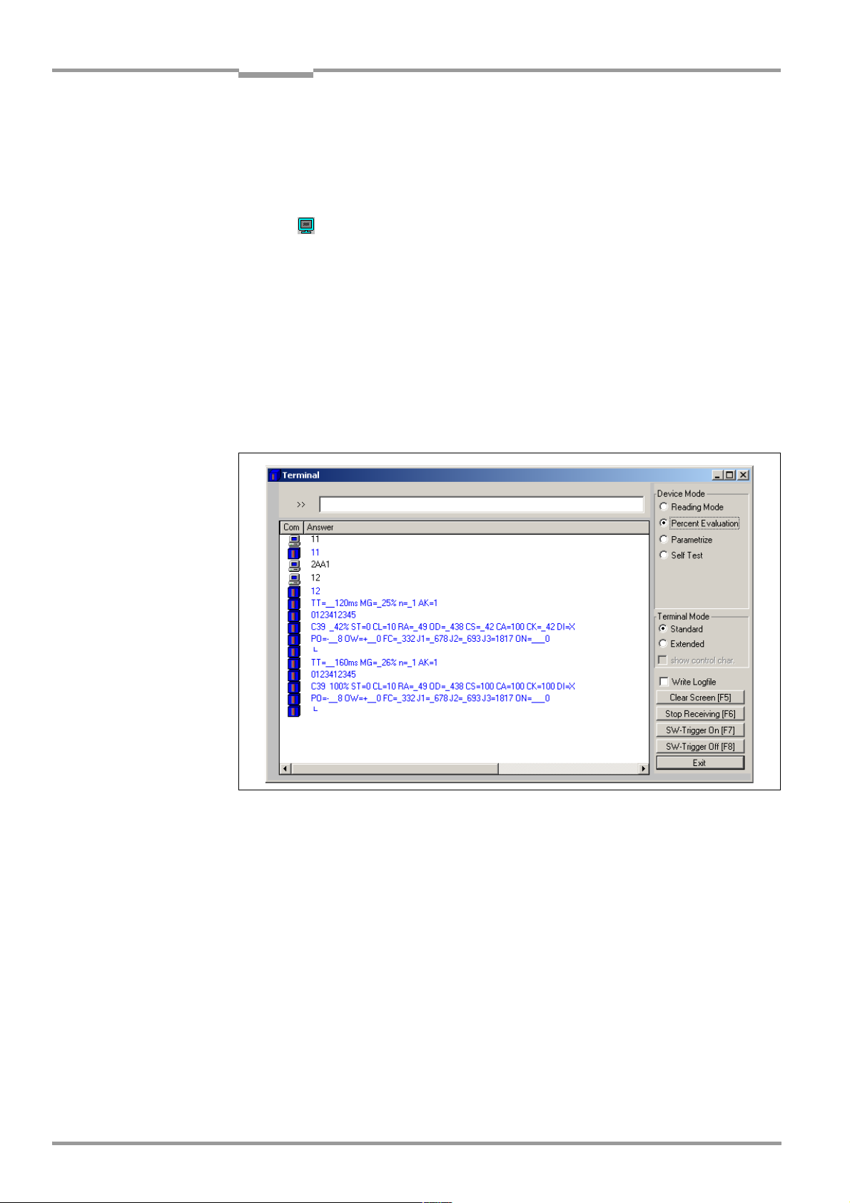
Chapter 6 Operating Instructions
Operation
CLX490 Compact OMNI Scanner
3. Perform a download to the CLX.
To do so, click the S
OWNLOAD PARAMETER in the context menu.
D
TANDARD option again with the right mouse button and choose
CLV-Setup copies the parameter to the CLX temporarily.
The CLX then operates with the standard decoder (until the CLX is switched off).
4. Click in the toolbar.
The Terminal Emulator window is displayed. The CLX is in the Reading mode.
5. In the D
EVICE MODE section, choose PERCENTAGE EVALuation
The dialog box for choosing the distance configuration is then displayed.
6. Choose the appropriate distance configuration for the reading distance:
– with autofocus mode the distance configuration no. 1
– with event-controlled focus control the distance configuration that corresponds to the
reading distance of the object (default setting: no. 1, focus position F1 = 1,200 mm).
7. Confirm the dialog box with OK.
The ”Device Ready” LED is extinguished. The CLX initiates the percentage evaluation
and outputs the reading results continuously. An example shows Fig. 6-5.
Fig. 6-5: CLV-Setup: Displaying the percentage evaluation in the Terminal Emulator
8. Present the bar code pattern from Fig. 6-1, Page 6-3 and monitor the reading results
in the Terminal Emulator window.
Note In default setting, the CLX operates in the autofocus mode "Minimum distance“. As a result,
the CLX focuses on the object that is nearest in Percentage Evaluation mode. The view on
the object with the scan line must be unobstructed, i. e. any other objects must not protude
into the autofocus space. If they do so, the autofocus mode "Differential background“ must
be selected. Alternatively a fixed focus position can be set.
The ”Read Result” LED also provides information on the reading quality:
– The LED is extinguished if reading quality is < 30 %
– The LED blinks twice per second if the reading quality is 30 % to 70 %
– The LED blinks five times per second if the reading quality is 70 % to 90 %
– The LED is lit continuously if the reading quality is > 90 %
6-18 © SICK AG · Division Auto Ident · Germany · All rights reserved 8009237/RB47/2007-08-03
Page 77
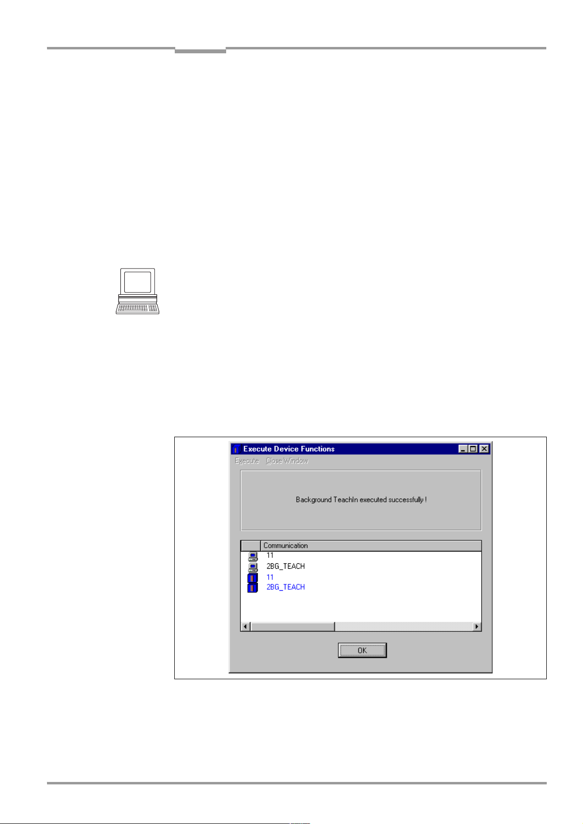
Operating Instructions Chapter 6
CLX490
Operation
The output format of the reading result is the same as that of the Reading mode. Fig. 6-3,
Page 6-16 explains the structure and function of the reading diagnosis data.
6.5.3 Background teach-in
If the Autofocus function is used in the D
AND TRACKING mode, the CLX must first learn the ambient background in its reading field to
IFFERENTIAL BACKGROUND or DIFFERENTIAL BACKGROUND
narrow the reading field even further. When the internal distance profile is set, the reading
field of the CLX must not contain any objects. In this mode, the CLX does not output any
reading results.
The background teach-in function can be started as a device function in the submenus
under CLX490, D
EVICE FUNCTIONS, BACKGROUND, TEACH-IN or press the [F2] key.
Starting the background teach-in:
1. Mount the CLX at the reading station and align it with an object containing a bar code.
2. Remove the object so that the CLX has an unobstructed view of the background.
3. Choose CLX490, D
EVICE FUNCTIONS, BACKGROUND, TEACH-IN
– or –
press the [F2] key.
The E
XECUTE DEVICE FUNCTIONS window opens.
Choose B
ACKGROUND, TEACH-IN in the EXECUTE menue.
The Device Ready LED extinguishes. The CLX then scans its background and learns the
ambient background so that it can create a suitable distance profile.
The CLX outputs a message once the teach-in procedure has been successfully completed (see Fig. 6-6).
The CLX has then learned the ambient background.
Fig. 6-6: CLV-Setup: Dialog window for running the background teach-in
4. Choose C
LOSE to close the window.
If the parameters in the CLX were modified as a result of the teach-in procedure, CLVSetup asks you whether you want to copy and display the modified parameter set by
uploading it from the CLX.
8009237/RB47/2007-08-03 © SICK AG · Division Auto Ident · Germany · All rights reserved 6-19
Page 78

Chapter 6 Operating Instructions
Operation
CLX490 Compact OMNI Scanner
5. Confirm the query with YES.
The CLX resumes Reading mode and the "Device Ready" LED lights up.
Displaying the taught-in background:
The new background distance profile can be uploaded and displayed in CLV-Setup via the
auxiliary interface of the CLX. CLV-Setup displays the background without any parameterized
limitations ("Autofocus space").
1. Choose the R
2. In the A
HOW BACKGROUND dialog box appears.
The S
EADING CONFIGURATION tab.
UTOFOCUS section, click the SHOW BACKGROUND button.
An example of a distance profile is shown in Fig. 6-7, with part A of the scan line.
Fig. 6-7: CLV-Setup: Display of the learned background
Note The CLX adjusts the entire profile of the taught-in background by minus 100 mm, that is, the
entire background curve is moved toward the CLX by this amount (also in the display in CLVSetup) to compensate measurement inaccuracies. The parameterized limits of the
applicable autofocus space are not corrected. The CLX also shifts the edges of the
measured profile toward the center by 2 angular elements.
If no background has been taught in, the CLX uses the default background (2,200 mm
across the entire distance profile).
6-20 © SICK AG · Division Auto Ident · Germany · All rights reserved 8009237/RB47/2007-08-03
Page 79

Operating Instructions Chapter 6
CLX490
Operation
6.5.4 Displaying and editing operating data
This function enables statistical operating data, which the CLX maintains in the form of counters during the reading procedure, to be displayed and reset.
The CLX does not output a reading result in this mode.
1. Click in the tool bar.
The CLX cancels the Reading mode and the "Device Ready" LED is extinguished. The
PERATING DATA dialog box appears (Fig. 6-8).
O
2. After checking/resetting the desired counters, click OK to confirm any changes made.
The CLX then returns to the Reading mode and the "Device Ready" LED lights up.
Fig. 6-8: CLV-Setup: "Operating Data" dialog box
6.5.5 Reading diagnosis
Function of the auxiliary interface. In this mode, the CLX outputs the data contents of all
the bar codes that were read – including those that, according to the evaluation criteria,
were not read properly and were thus incorrect – together with the associated reading diagnosis data via the auxiliary interface. The number of bar codes output can, therefore, be
higher than the number of those that were sent via the host interface in the reading result.
In the default setting, this mode is selected for the auxiliary interface.
Fig. 6-3, Page 6-16 shows the output format of the auxiliary interface.
In the default setting, the CLX doesn’t output any reading diagnosis data via the host interface.
If the reading diagnosis is to remain inactive, this can be set via the A
UXILIARY INTERFACE tab.
1. In the AUXILIARY INTERFACE drop-down list, choose READ DIAGNOSTICS.
2. Perform a download to the CLX by clicking in the toolbar.
The D
OWNLOAD PARAMETERS dialog box is then displayed.
3. Choose the P
ERMANENT storage option in the dialog box.
8009237/RB47/2007-08-03 © SICK AG · Division Auto Ident · Germany · All rights reserved 6-21
Page 80

Chapter 6 Operating Instructions
Operation
CLX490 Compact OMNI Scanner
The auxiliary interface is now set to the "Read Diagnostics" mode.
6.5.6 Monitor Host Interface
Function of the auxiliary interface. In this mode, the CLX outputs the data traffic of its host
interface via the auxiliary interface. Protocol driver handshakes and protocol-specific data,
such as start and stop characters, are suppressed here. Each data string is displayed on a
separate line on the screen. Two monitoring modes are available that differ with regard to
the data output format (Table 6-9).
Mode Direction of data Output format Representation on screen
"Monitoring host interface" CLX receives from host
CLX sends to host
"Monitoring host interface 2" CLX receives from host
CLX sends to host
Table 6-9: "Monitor Host Interface" function
<STX> I Data <CR> <LF> <ETX>
<STX> O Data <CR> <LF> <ETX>
<STX> Data <ETX>
<STX> Data <ETX>
I Data
O Data
Data
Data
The MONITOR HOST INTERFACE or MONITOR HOST INTERFACE 2 function is activated via the AUXI-
LIARY INTERFACE tab.
1. In the A
H
UXILIARY INTERFACE drop-down list, choose MONITOR HOST INTERFACE or MONITOR
OST INTERFACE 2.
2. Perform a download to the CLX.
To do so, click the desired option in the list again with the right mouse button and
choose D
OWNLOAD PARAMETER in the context menu.
CLV-Setup copies the parameter to the CLX temporarily.
The auxiliary interface then operates in the choosed "Monitor Host Interface" mode until
the CLX is switched off again.
Note On good read, the CLX only outputs the number of read bar codes being defined for
maximum on the C
ODE CONFIGURATION tab, in the NUMBER OF CODES section.
Displaying the data traffic of the host interface in the Terminal Emulator:
The data traffic of the host interface can be displayed in the Terminal Emulator of CLV-Setup.
Fig. 6-9 shows an example of how the reading result can be output.
1. Choose the serial interface as the external trigger source for the reading pulse.
See Chapter 6.5.1 Reading mode (standard operating mode), Page 6-14.
2. Click in the toolbar.
The Terminal Emulator window is then displayed.
The CLX is in the Reading mode.
3. Click on the SW-T
RIGGER ON button or press [F7].
The red scan line then appears as a cross.
4. Present the bar code pattern from Fig. 6-1, Page 6-3.
5. Click the SW-T
RIGGER OFF button or press [F8].
CLV-Setup outputs the reading result in the Terminal Emulator.
Example: "O 0123412345".
6-22 © SICK AG · Division Auto Ident · Germany · All rights reserved 8009237/RB47/2007-08-03
Page 81

Operating Instructions Chapter 6
CLX490
Operation
Fig. 6-9: CLV-Setup: Displaying the reading result of the host interface in the Terminal Emulator
with direction identifier at the beginning (in this case: O = Output)
Note If a large amount of data is being read in at high speed and with a high transmission rate,
the host interface’s data trafficing may no longer be completely displayed on the auxiliary
interface (display "..."). This is due to the slower transmission rate of the auxiliary interface
(9,600 bd).
In the default setting, the CLX sends the following in the data output string of the host interface:
• On Good Read: Data content of one bar code
• On No Read: Character string "NOREAD"
The "Header", "Code-Info/Separator", "Splitter" and "Terminator" blocks are blank.
Tip
The structure of the data output string of the host interface can be configured via the DATA
TRINGS tab.
S
• Up to 10 elements, consisting of constants (letters, digits, control characters) and/or
reading diagnosis data, can be entered in the "Header", "Code-Info/Separator",
"Splitter" und "Terminator" blocks.
• Up to 5 elements, consisting of constants (letters, digits, control characters) can be
entered in the "Splitter" blocks.
• The position of the "Code-Info/Separator" block can be choosen before or after the
code.
1. Choose the D
2. Click the H
DIT PARAMETER: TFH dialog box is then displayed.
The E
ATA STRINGS tab.
EADER field.
3. Click the desired constants or placeholders for the reading diagnosis data.
The selected elements appear in the text box at the top of the dialog box in the
sequence in which they were selected.
4. Confirm the entries made by clicking OK.
5. Repeat this procedure for the "Code-Info/Separator", "Splitter" und "Terminator"
blocks.
8009237/RB47/2007-08-03 © SICK AG · Division Auto Ident · Germany · All rights reserved 6-23
Page 82

Chapter 6 Operating Instructions
Operation
CLX490 Compact OMNI Scanner
6. Perform a download to the CLX by clicking in the toolbar.
OWNLOAD PARAMETERS dialog box is then displayed.
The D
7. Choose the P
ERMANENT storage option in the dialog box.
The CLX outputs the selected elements in the data output string of the host interface
with the next reading result.
6.5.7 Auxiliary input
Function of the auxiliary interface. In this mode, the CLX accepts a bar code entered at the
auxiliary interface (via the keyboard or handheld scanner with decoder). It sends the bar
code to the host in a separate data string via its host interface. No reads can, therefore, be
corrected by transmitting missing bar codes subsequently.
Chapter 10.10.1 Auxiliary input via auxiliary interface, Page 10-29 describes this function
and the associated procedure in greater detail.
6.5.8 Self-test
After the CLX has been switched on, it performs a self-test before it is initialized with the parameter set. The test can be called up explicitly at any time via CLV-Setup. During the selftest, the CLX checks that its hardware components are functioning correctly. A final message via the auxiliary interface provides information on the test result. The CLX does not output
a reading result during the test routine.
1. Click in the toolbar.
The Terminal Emulator window is then displayed. The CLX is in the Reading mode.
2. In the D
EVICE MODE section, choose SELF TEST.
The "Device Ready" LED is extinguished. The CLX cancels the Reading mode and starts
the test routine.
After a few seconds, the CLX outputs the encoded test result in the form of a code
number (Fig. 6-10).
3. To return to the Reading mode, click R
EADING MODE or close the terminal emulator.
The CLX then returns to the Reading mode and the "Device Ready" LED lights up.
Fig. 6-10: CLV-Setup: Displaying the self-test result in the terminal emulator
6-24 © SICK AG · Division Auto Ident · Germany · All rights reserved 8009237/RB47/2007-08-03
Page 83

Operating Instructions Chapter 6
CLX490
Operation
The code number ”15000” means that the self-test was completed successfully and that
no faults were diagnosed.
Chapter 8.3.1 CLX without external parameter memory, Page 8-2, lists the error keys toge-
ther with the associated corrective measures.
6.5.9 Executing CLX functions interactively
CLV-Setup enables a number of CLX functions to be executed interactively. CLV-Setup
prompts the user to carry out specific actions and provides information on the progress of
the function being executed.
The following functions are available:
• Background teach-in/reset (default setting)
• Percentage evaluation
• Copy parameter memory
• Analyze scanner network
• Activate factory defaults in device
¾ Choose CLX490, D
EVICE FUNCTIONS and the desired funktion
– or –
press the [F2] key.
XECUTE DEVICE FUNCTIONS dialog box is then displayed.
The E
Choose the desired function in the E
XECUTE menu in the menu.
CLV-Setup starts the function and, where appropriate, prompts the user to carry out the
necessary actions.
6.6 CLX messages
The CLX outputs encoded system and error messages via the auxiliary interface to report
user actions or events in the reading process. When the system is started, the CLX also
outputs system messages in plain text (English). If configured accordingly, the CLX transfers
the error status ST in the data output string of the host interface.
6.6.1 Displaying messages
In the 4th field from the left in the status bar at the bottom of the screen, CLV-Setup displays
system and error messages that occur at the auxiliary interface of the CLX. These are
recorded in a file, which is continuously updated. The messages have the following format:
• System message: "CLV SYS-Message: xxx"
• Error message: "CLV SYS-Failure: xxx"
The additional system messages in plain text can be displayed in the terminal emulator if
CLV-Setup and the terminal emulator are started before the CLX is connected.
Additional messages:
When the system is started, these system messages inform the user whether the starting
process was successful. No further measures are normally required.
Chapter 10.5 System messages, Page 10-14 explains the contents of the messages.
Error messages:
Error messages indicate the following types of error:
• a device defect
8009237/RB47/2007-08-03 © SICK AG · Division Auto Ident · Germany · All rights reserved 6-25
Page 84

Chapter 6 Operating Instructions
Operation
CLX490 Compact OMNI Scanner
• incorrect parameter settings
• errors during data transmission to the host
Chapter 8.3 Error messages, Page 8-2 lists the messages with the associated corrective
measures.
Note To call up the most recent error to occur in the CLX, enter command "2?SF" in the command
line of the terminal emulator.
6.7 Switching off the CLX
1. If the parameter set was modified in CLV-Setup or was only stored temporarily in CLX
via a download ("Temproray" option or via context menu (right mouse button)), the
parameter set must be stored permanently in the CLX by choosing the P
storage option.
2. Save the parameter set as a configuration file "*.scl" in CLV-Setup.
3. Switch off the power supply of the AMV/S60 or unplug both of the CLX’s connecting cables from the connection module.
The last parameter set stored permanently in the CLX remains valid.
ERMANENT
Archiving the parameter set:
We recommend that you print out the configuration file in order to archive the parameter set.
1. Click in the toolbar.
RINT FILE dialog box is then displayed.
The P
2. Enter a comment in the input field in order to assign the printout to the CLX.
Confirm your entry with OK.
The P
RINT dialog box for configuring the printer is then displayed.
3. Make the necessary entries in the dialog box and confirm these.
CLV-Setup prints out the current configuration file in the form of a table.
6-26 © SICK AG · Division Auto Ident · Germany · All rights reserved 8009237/RB47/2007-08-03
Page 85

Operating Instructions Chapter 7
CLX490
Maintenance
7 Maintenance
7.1 Maintenance during operation
The CLX functions maintenance free. Maintenance is not required to guarantee laser
class 2 of the CLX.
Note Don’t open the device. The warranty will be forfeited if the device is opened.
The CLX indicates any faults or malfunctions by outputting coded system and error messages (e. g. "CLV SYS-Failure: 071") via its auxiliary interface. The messages are displayed in
the "CLV-Setup" program window in the fourth field from the left on the bottom, in the status
line (see also Chapter 8.3 Error messages, Page 8-2). CLV-Setup logs the messages in a
file.
7.2 Cleaning the CLX
Recommendation In order to make use of the full optical reading capacity of the CLX, the reading window
should be checked regularly (e. g. weekly) for soiling. This is especially recommended when
operating the device in harsh conditions (dust, abrasion, humidity, finger prints, etc.).
7.2.1 Cleaning the front window
Laser beam can cause blindness!
The CLX uses a class 2 red-light laser. Looking directly at the laser beam can seriously
damage your eyesight.
¾ As with sunlight, never look directly into the laser beam.
¾ Switch off the device while it is being cleaned.
¾ Never look directly into the reading window while the device is in operation.
Damage on the reading window!
The reading window is made of glass. Scratches and streaks on the window will reduce the
reading performance.
¾ Do not use aggressive cleaning agents.
¾ Do not use cleaning agents which cause increased abrasion (e. g. powder).
¾ Avoid cleaning motions at the reading window which could cause scratches or abrasion.
Cleaning the reading window
Note Electrostatic charges cause dust particles to stick to the reading window.
This effect can be combated by using anti-static SICK synthetic cleaner (no. 5600006) in
combination with a SICK lens cloth (no. 4003353).
¾ Use a clean, soft brush to free the reading window (Fig. 7-1, Page 7-2) from dust.
¾ If necessary, additionally clean the reading window with a clean, damp, lint-free cloth
and a mild, anti-static window cleaning fluid.
8009237/RB47/2007-08-03 © SICK AG · Division Auto Ident · Germany · All rights reserved 7-1
Page 86
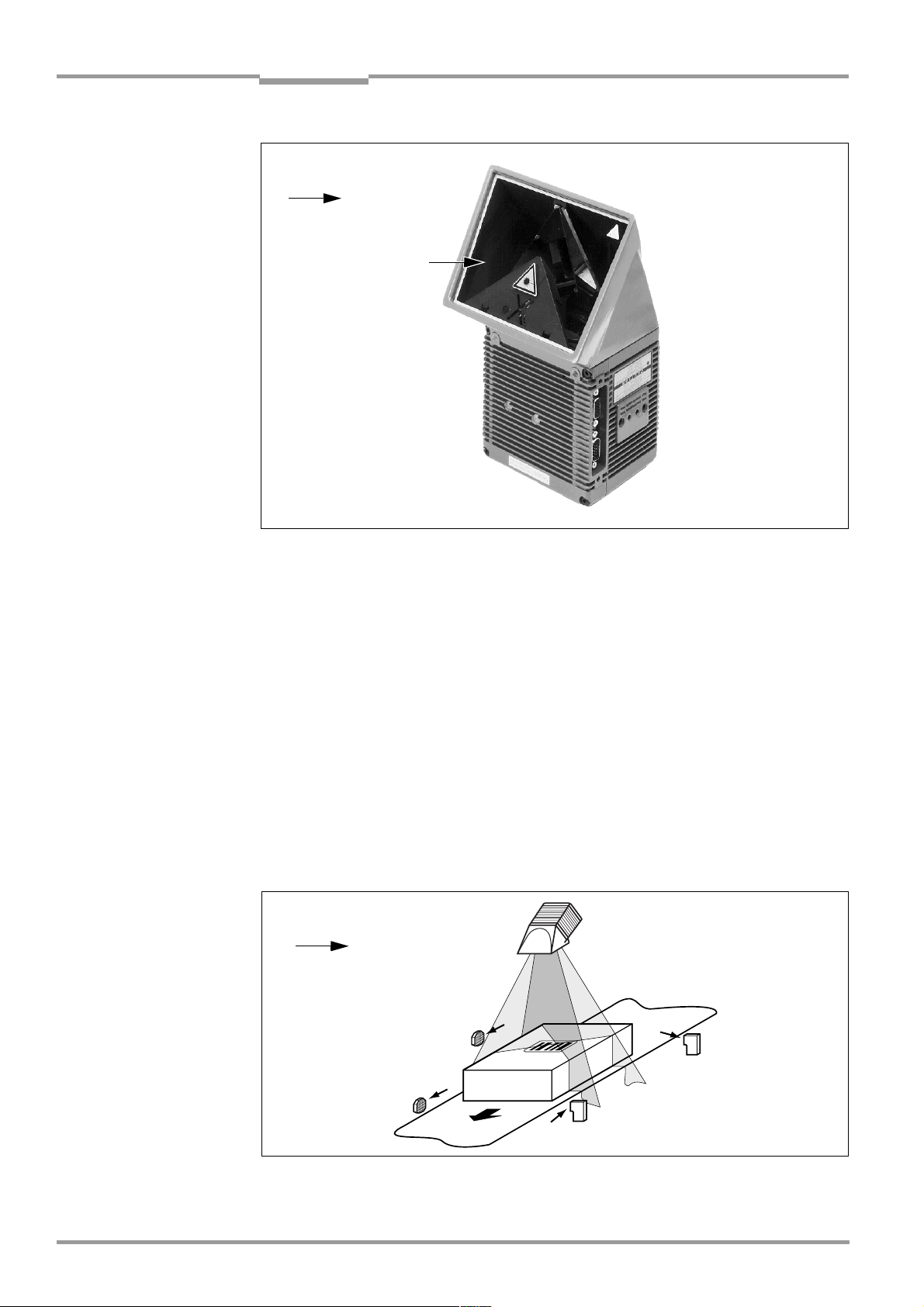
Chapter 7 Operating Instructions
Maintenance
CLX490 Compact OMNI Scanner
Clean here
Fig. 7-1: Cleaning the reading window
If the reading window is scratched or damaged (cracked, broken), it must be replaced.
Please contact the SICK Service.
Cleaning the housing
In order to ensure sufficient cooling for the CLX, make sure that the housing is always clean.
¾ Use a soft brush to free the housing from dust.
¾ If necessary, clean the LEDs on the rear of the device.
7.2.2 Cleaning other optical surfaces
If an external reading pulse generator and/or object-height detection sensors are used
(e.g. photoelectric reflex switches), further sensors with optical effective surfaces can be installed. Soiling of these surfaces can cause incorrect switching behaviour.
¾ In order to prevent incorrect switching behaviour, remove soiling from the optical effec-
tive surfaces of the external sensors.
Clean here
Fig. 7-2: Cleaning the external optical sensors (reading pulse generator, object-height detector)
7-2 © SICK AG · Division Auto Ident · Germany · All rights reserved 8009237/RB47/2007-08-03
Page 87

Operating Instructions Chapter 7
CLX490
Maintenance
7.3 Checking the incremental encoder
If an incremental encoder is used, check the correct position on the conveyor.
¾ Ensure that the incremental encoder always contact the conveyor so that the friction
wheel turns without slipping.
7.4 Disposal
Irreparable devices or devices that are no longer required must be disposed of in an
environmentally-friendly manner:
1. Always observe the applicable national waste disposal regulations.
2. Remove the CLX housing.
3. Remove the electronic modules.
4. Send the chassis and cover (aluminium) to be recycled.
5. Send the electronic modules for disposal as problem waste.
At present, SICK AG does not accept any unusable or irreparable devices.
8009237/RB47/2007-08-03 © SICK AG · Division Auto Ident · Germany · All rights reserved 7-3
Page 88

Chapter 7 Operating Instructions
Notes:
Maintenance
CLX490 Compact OMNI Scanner
7-4 © SICK AG · Division Auto Ident · Germany · All rights reserved 8009237/RB47/2007-08-03
Page 89

Operating Instructions Chapter 8
CLX490
Troubleshooting
8 Troubleshooting
8.1 Overview of the possible errors and malfunctions
8.1.1 Mounting errors
• CLX aligned incorrectly with the object carrying the bar code (e. g. blanking)
• Reading pulse sensor positioned incorrectly
• With event-controlled focus control: sensors for object height detection positioned
incorrectly
8.1.2 Electrical installation errors
• Interfaces on the CLX connected incorrectly (wiring error in AMV/S60)
• Host interface on AMV/S60 configured incorrectly
8.1.3 Parameter errors
• Functions not adjusted to local conditions, e. g. communication parameters on the host
interface are set incorrectly
• Technical limits of the device exceeded, e. g. relationship between the scanning
frequency and the reading distance
8.1.4 Malfunctions
• Start/stop mode: no external reading trigger, more than one object in the reading field
• Tracking mode: gap between the objects in conveying direction fallen below minimum
• Laser timeout for incorrectly terminated reading pulse
• Device error (hardware/software)
8.2 Monitoring error and malfunctions
The CLX is self-monitoring:
• After the power supply has been switched on, the CLX automatically carries out a selftest, in which it checks important hardware components, before it is initialized (parameter set loaded and device functions initialized). The self-test can be repeated at any
time by cancelling Reading mode. See Chapter 6.5.8 Self-test, Page 6-24.
• If the CLX detects an error during the self-test or at any other time, it outputs the error
status ST=3 on the host interface. Prerequisite: the error status is enabled for transmission. This is disabled by default. The CLX displays the diagnosed error as a numeric
combination on the auxiliary interface (see Table 8-1, Page 8-2).
• While it is in operation, the CLX constantly monitors the laser diode and speed of the
polygon mirror wheel. In addition, a watchdog circuit responds to error statuses. The
CLX carries out referencing at regular cycles. To do so, the laser diode is switched on
for max. 10 s.
• A timer (laser timeout) automatically deactivates the laser diode in Reading mode
("Sensor input" and "Serial interface trigger" mode) if the reading interval has not ended
after 10 minutes (default setting). However, it does not end the reading interval. In this
case, the CLX outputs the message: "Laser safety timeout" on the auxiliary interface. The
reading interval must be terminated by resetting the trigger signal. The laser diode is
activated again by the next reading trigger.
8009237/RB47/2007-08-03 © SICK AG · Division Auto Ident · Germany · All rights reserved 8-1
Page 90

Chapter 8 Operating Instructions
Troubleshooting
CLX490 Compact OMNI Scanner
8.3 Error messages
The CLX outputs coded error message (number combinations) via the auxiliary interface
only. Table 8-1 contains a list of the messages.
Displaying messages:
To display the messages on the PC, proceed as follows in CLV-Setup:
¾ Click in the toolbar.
The Terminal Emulator is launched.
CLV-Setup logs the error messages automatically in a file (sys_msg.log).
8.3.1 CLX without external parameter memory
Message Meaning Possible cause Remedy
)
"CLV SYS-Failure: xxx" The CLX has diagnosed a
system error.
The "Device Ready" LED does
not light up or extinguishes.
The system is restarted.
Table 8-1: Error messages output on the auxiliary interface
Error key:
011 Data error (RAM)
012 Address error (RAM)
013 RAM to small
051 Speed out of tolerance
061 Mirror interval out of
071 Error: laser shutter
091to095Error: focus control
101to118Error: external parame-
130 Amplifier error
131 Background profile
132 Center reading angle
133 Brightness overflow
201to215DSP error
1
(mirror wheel)
tolerance
ter memory
invalid
RA 50 implausible
If the error occurs again after the
CLX is restarted, contact the SICK
Service department.
1) Deactivate the CAN interface
to suppress error numbers above
300 (not relevant in stand-alone
mode). To do so, upload the
parameter set from the CLX using
CLV-Setup, choose the CAN
NTERFACE tab and deactivate the
I
function in the CAN I
UNCTION section.
F
Download the parameter set to
the CLX!
NTERFACE
8-2 © SICK AG · Division Auto Ident · Germany · All rights reserved 8009237/RB47/2007-08-03
Page 91

Operating Instructions Chapter 8
Troubleshooting
CLX490
8.3.2 LED error messages for the external parameter memory
The CLX also reports errors accessing the external parameter memory by means of the
"Device Ready" and "Read Result" LEDs.
LED behavior Meaning Possible cause Remedy
1. When the device is
switched on, the "Device
Ready" LED blinks for approx. 10 s and then lights
up constantly.
2. When the device is switched on, the "Device Ready" and "Read Result"
LEDs blink for approx.
10 s.
The "Device Ready" LED
Start option: S
XTERNAL PARAMETERS.
E
The CLX has successfully loaded
the external parameter set to its
RAM.
Start option: S
E
XTERNAL PARAMETERS.
The CLX has successfully
loaded the external parameter
set with tolerated errors
RAM
then lights up constantly.
3. The "Device Ready" LED
lights up constantly when
the device is switched on.
• Start option: START WITH
E
XTERNAL PARAMETERS.
The CLX has not loaded external parameter set. Instead,
it has loaded the internal parameter set to its RAM.
• Start option: S
INTERNAL PARAMETERS.
The CLX has successfully
loaded the internal parameter set to its RAM.
4. When the device is switched on, the "Device
Ready" LED and "Read
Result" LEDs blink
continuously
2)
.
• Start option: S
TERNAL PARAMETERS.
The CLX has not loaded the
external parameter set.
Instead, it has loaded the
internal parameter set to its
RAM. The CLX, however,
does not output data on the
host interface.
• Start option: S
NTERN –> EXTERN.
I
The CLX was not ab le to copy
the internal parameter set to
the external memory.
It has loaded the internal parameter set to its RAM.
1) The software of the parameter set in the CLX is older than that of the parameter set in the external memory: print out the parameter set using CLV-Setup. If necessary,
display the ID of the unknown/errored command group(s) using the <STX> 8?ERR <ETX> command in the Terminal Emulator window of CLV-Setup. Decode the ID using
the reference manual entitled Command Language of the CLV Bar Code Scanners and check the relevant parameter values in the tabs.
The software of the parameter set in the CLX is newer than that of the parameter set in the external memory: all of the new parameters in the CLX are set to the default
values. If these parameters are necessary, edit the values in the relevant tabs in CLV-Setup and download them to the CLX and the external memory.
2) Flashing stops when the device switches from Reading mode to Parameter mode (e. g. during download from CLV-Setup).
Table 8-2: LED error messages for access to the external parameter memory
TART WITH
TART WITH
1)
TART WITH
TART WITH EX-
TART WITH COPY
to its
–None.
Transfer ok, but different parameter versions in the external mem-
Upload parameter set to CLVSetup and check parameters
1)
.
ory and CLX.
• External parameter memory not
connected.
• OK if the device is to be
operated without an external
parameter memory.
• Check whether the external
parameter memory is connected correctly (free wiring: check
wire assignment).
• Start ok.
• External parameter memory not
• None.
• See 3 Remedy.
connected.
• The parameter set in the external memory is not from a
CLX490.
• The external parameter memory is defective.
• Use the correct external parameter memory or overwrite the
current one.
• Repeat the startup procedure.
If the error is still present after
following 4 Remedy, 1st and
2nd paragraph, contact the
SICK Service department.
• External parameter
memory is not connected.
• Ensure that the external parameter memory is connected
correctly (free wiring: check
wire assignment).
• Data transmission error.
• Repeat the startup procedure.
If the error is still present after
following 4 Remedy, 2nd and
3rd paragraph, contact the
SICK Service department.
• Internal parameter set too large
to be copied to the external me-
• Contact the SICK Service
department.
mory (memory is full).
• The external parameter memo-
• See 4 Remedy, 3rd paragraph.
ry is defective.
8009237/RB47/2007-08-03 © SICK AG · Division Auto Ident · Germany · All rights reserved 8-3
Page 92

Chapter 8 Operating Instructions
Troubleshooting
CLX490 Compact OMNI Scanner
LED behavior Meaning Possible cause Remedy
5. When the device is switched on, the "Device
Ready" LED and "Read
Result" LEDs blink alternately for approx. 10 s.
The "Device Ready" LED
then lights up constantly.
Start option: S
I
NTERN –> EXTERN.
The CLX has successfully
copied the internal parameter
set to the external-memory
and set the option for the next
start to START WITH EXTERNAL
ARAMETERS.
P
TART WITH COPY
Transfer ok. Not applicable.
3)
It has loaded the internal parameter set to its RAM.
3) The parameter set stored in the external memory is not checked automatically to determine whether it can be read. To check the parameter set, switch off the power
supply to the CLX briefly and monitor the "Device Ready" LED as described under 1.
Table 8-2: LED error messages for access to the external parameter memory (contd.)
8-4 © SICK AG · Division Auto Ident · Germany · All rights reserved 8009237/RB47/2007-08-03
Page 93

Operating Instructions Chapter 8
Troubleshooting
CLX490
8.3.3 Messages for errors accessing the external parameter memory
The CLX outputs further error messages, in addition to the general error messages in
Chapter 8.3.1 CLX without external parameter memory, Page 8-2, if problems arise when
the external parameter memory is accessed.
Message Meaning Possible cause Remedy
1. "error: access to external
parameters not successful
internal parameters
loaded"
(Error type: 104, 105,
106, 111, 112,115)
• Start option: S
TERNAL PARAMETERS.
The CLX has not loaded the
external parameter set. Instead, it has loaded the internal parameter set to its RAM.
The CLX, however, does not
output data on the host interface.
• Start option: S
NTERN –> EXTERN.
I
The CLX was not ab le to copy
the internal parameter memory. It has loaded the internal parameter set to its RAM.
2. "error: external parameter
memory full
internal parameters
loaded"
(Error type: 108)
Start option: S
NTERN –> EXTERN.
I
The CLX was not able to copy
the internal parameter memory.
It has loaded the internal parameter set to its RAM.
3. "error: external parameters
not valid for device
internal parameters
loaded"
(Error type: 116)
Start option: S
NAL PARAMETERS.
The CLX has not loaded the
external parameter set. Instead,
it has loaded the internal parameter set to its RAM. The CLX,
however, does not output
data on the host interface.
4. "error: no external para-
meter memory connected
internal parameters
loaded"
(Error type: 102)
• Start option: S
TERNAL PARAMETERS.
The CLX has not loaded the
external parameter set. Instead, it has loaded the internal parameter set to its RAM.
• Start option: S
I
NTERN –> EXTERN.
The CLX was not ab le to copy
the internal parameter set to
the external memory. It has
loaded the internal parameter set to its RAM.
5. "error: writing parameters
CLV->EXT internal parameters loaded"
(Error type: 110, 111,
112)
Start option: S
I
NTERN –> EXTERN.
The CLX was not able to copy
the internal parameter set to
the external memory. It has
loaded the internal parameter
set to its RAM
Table 8-3: For messages for problems accessing the external parameter memory
TART WITH EX-
TART WITH COPY
TART WITH COPY
TART WITH EXTER-
TART WITH EX-
TART WITH COPY
TART WITH COPY
The external parameter memory is
defective.
Repeat the startup procedure. If
the error is still present, contact
the SICK Service department.
The internal parameter set is too
large for the external memory
Contact the SICK Service department.
(memory is full).
The parameter set in the external
memory is not from a CLX490.
Use the correct external parameter memory or overwrite the current one.
• External parameter memory not
connected.
• OK if the device is to be operated without an external parameter memory.
• Check whether the memory is
connected correctly (free
wiring: check wire assignment).
• External parameter memory not
• See 5 Remedy 2nd paragraph
connected.
Data transmission error. Check whether the external para-
meter memory is connected correctly (free wiring: check wire
assignment).
Repeat the startup procedure. If
the error is still present, contact
the SICK Service department.
8009237/RB47/2007-08-03 © SICK AG · Division Auto Ident · Germany · All rights reserved 8-5
Page 94

Chapter 8 Operating Instructions
Troubleshooting
CLX490 Compact OMNI Scanner
Message Meaning Possible cause Remedy
6. "warning: additional
unknown parameter(s)
external parameters
loaded"
(Error type: 101, 114)
Start option: START WITH
E
XTERNAL PARAMETERS.
The CLX has successfully
loaded the external parameter
1)
set with tolerated errors
to its
Transfer ok but different parameter versions in the external
memory and the CLX.
Upload the parameter set to CLVSetup and check the values
1)
.
RAM.
1) The software of the parameter set in the CLX is older than that of the parameter set in the external memory: print out the parameter set using CLV-Setup. If necessary,
display the ID of the unknown/errored command group(s) using the <STX> 8?ERR <ETX> command in the Terminal Emulator window of CLV-Setup. Decode the ID using
the reference manual entitled Command Language of the CLV Bar Code Scanners and check the relevant parameter values in the tabs.
The software of the parameter set in the CLX is newer than that of the parameter set in the external memory: all of the new parameters in the CLX are set to the default
values. If these parameters are necessary, edit the values in the relevant tabs in CLV-Setup and download them to the CLX and the external memory.
Table 8-3: For messages for problems accessing the external parameter memory (contd.)
8-6 © SICK AG · Division Auto Ident · Germany · All rights reserved 8009237/RB47/2007-08-03
Page 95

Operating Instructions Chapter 8
Troubleshooting
CLX490
8.4 ST error status in the reading result of a bar code
Value Meaning Possible cause Remedy
0 Good Read. – None
2 No bar code of the enabled code type
found according to the evaluation
criteria.
3 Device fault. Device fault. Call up the self-test. See Chapter 6.5.8
5 Required number of successful multiple
reads for the bar code not reached.
6Master:
Number of slave reading results does
not match the parameterized number of
slaves.
7 The source of the reading result is the
auxiliary input via the auxiliary interface.
9
The OUTPUT FILTER function is activated
for the code comparison. The CLX has
detected valid bar codes. However,
these do not match the active match
code(s).
AThe C
HECK MAX. NUMBER OF CODES
function is active. The number of valid
bar codes detected by the CLX in Reading mode exceeds that specified under
UMBER OF CODES: MAXIMUM.
N
It repeatedly outputs the defined error
string until the number specified under
UMBER OF CODES: MINIMUM is reached.
N
DThe C
ODE 32 evaluation option is activa-
ted for Code 39. The CLX is attempting
to interpret 6-digit C39 bar codes as
C32 bar codes (output as 9-digit decimal values).
• No bar code in the CLX‘s reading
field during the reading pulse.
• Code type/length in the CLX not
enabled for decoding.
• Reading window obstructed/dirty.
• Conveyor speed of the object is too
high.
• Scanning frequency is too low.
• Ladder-type arrangement for bar
code relative to the conveyor direction: code height (bar length) too
poor.
• Print quality too poor.
• The parameterized number of slaves
does not match the actual number of
slaves available.
• The master timeout is too short.
• The data connection between the
slaves and/or the master has been
interrupted.
The bar code was not detected by the
reading function of the CLX, but was
entered subsequently with the auxiliary
function of the auxiliary interface and
sent to the host in a separate data
string.
The scanned object does not have a bar
code that matches the specified match
code.
One object in a set of objects with a
constant number of bar codes, for
example, contains more bar codes than
defined in the application.
The read 6-digit bar code is not a C32
bar code. The CLX outputs the defined
error string instead.
• Synchronize the pulse of the CLX with
the entry of a bar code into the
reading field.
• Correct the code configuration parameters.
• Check the reading window.
Self-test, Page 6-24.
If result ≠ 15000: Contact the SICK Service department.
• Check the conveyor speed.
• Adjust the scanning frequency.
• Check the code height.
• Check the print quality.
• Check the entered number of slaves.
• Check the master timeout setting.
• Check the cables between the slaves
and the master.
–
–
This message is used to indicate
errors on the objects (e. g. check
whether objects are homogeneous:
mixed with incorrect objects).
–
Table 8-4: Meaning of the ST error status in the reading result
8009237/RB47/2007-08-03 © SICK AG · Division Auto Ident · Germany · All rights reserved 8-7
Page 96

Chapter 8 Operating Instructions
Troubleshooting
CLX490 Compact OMNI Scanner
Value Meaning Possible cause Remedy
FThe CHECK MIN. NUMBER OF CODES
function is active.
The number of valid codes detected by
the CLX in Reading mode is less than
One object in a set of objects with a
constant number of codes, for example,
contains fewer codes than defined in
the application.
This message is used to indicate errors
on the objects (e. g. check whether
objects are homogeneous: mix with
incorrect objects).
that specified under NUMBER OF CODES:
INIMUM.
M
Instead of the code contents, it outputs
the defined error string in the quantity
defined under N
INIMUM
M
UMBER OF CODES:
Table 8-4: Meaning of the ST error status in the reading result
8-8 © SICK AG · Division Auto Ident · Germany · All rights reserved 8009237/RB47/2007-08-03
Page 97

Operating Instructions Chapter 8
CLX490
Troubleshooting
8.5 Troubleshooting
The following are required for troubleshooting purposes using the tables below:
• These Operating Instructions
• Tools
• A tape measure (up to 2,000 mm)
• A digital measuring device (current/voltage mesurement)
• A PC running CLV-Setup
• A 3-core RS 232 data cable (null modem cable), pins 2 and 3 crossed,
e. g. no. 2014054
8.5.1 General malfunctions: CLX not ready
Malfunction Possible cause Remedy
The "Device Ready" LED is not lit.
The "Result 1" output is not outputting a
pulse (default setting: Device Ready)
After switching on the power supply:
• The CLX has no power
• The CLX has diagnosed a
device error during the self-test
• Check wiring (power connector fitted securely to the AMV/S60 Connection
Module).
Measure voltage at pin 1 and pin 5.
• Switch CLX off and on again. Does the
LED light up? If not, contact SICK Service
department
During operation:
• The CLX is not in "Reading" mode
• The CLX has deactivated the laser diode
10 min. (default setting) after the start of
the current reading pulse (Trigger mode:
sensor input/serial interface)
Table 8-5: Troubleshooting: restoring operation (Reading mode)
• Return to Reading mode using the "CLVSetup" program. See Chapter 6.5.1
Reading mode (standard operating
mode), Page 6-14
• Terminate reading pulse. Check the reading pulse function. Supply new pulse.
See Chapter 6.4.3 Guide to parameteri-
zation menu, Page 6-8, Section Adjust
Laser timeout
8009237/RB47/2007-08-03 © SICK AG · Division Auto Ident · Germany · All rights reserved 8-9
Page 98

Chapter 8 Operating Instructions
Troubleshooting
CLX490 Compact OMNI Scanner
8.5.2 Malfunctions in Reading mode: reading trigger errors
¾ Check whether the "Device Ready" LED lights up.
If the LED does not light, see Table 8-5, Page 8-9.
CLX in stand-alone configuration
Malfunction Possible cause Remedy
1. Trigger mode:
Sensor input (external sensor).
The CLX cannot be clocked:
– the "Sensor" LED does not light up
– the red scan line does not appear
2. Trigger mode:
Serial interface
The CLX cannot be clocked:
– the "Sensor" LED does not light up
– the red scan line does not appear
3. CLX does not respond to an
external signal that ends the reading
pulse (sensor input, serial interface)
• Sensor not connected or connected to
incorrect switching input.
• If sensor supplied by CLX: sensor not
connected to ground potential.
• Incorrect reading pulse source parameterized in the CLX.
• Photoelectric switch not aligned with the
reflector (photoelectric proximity switch/
inductive sensor not dampened).
• Incorrect reading pulse source parameterized on the CLX.
• The CLX is not receiving any command
strings to start the reading interval on the
data interface.
Incorrect end of reading pulse parameterized on the CLX.
• Connect sensor to "Sensor" switching
input. Check sensor wiring (see Fig. 5-4,
Page 5-16). Measure output signal on
sensor.
• Insert jumper between pin 5 and pin 15.
• In the "CLV-Setup" program: choose the
D
EVICE CONFIGURATION tab, READING
RIGGER SOURCE section: is Sensor input
T
selected? (active high: reading pulse
starts when power applied)
• Align sensor.
Check functioning.
• In the "CLV-Setup" program: choose the
EVICE CONFIGURATION tab, READING
D
T
RIGGER SOURCE section: is serial interface
selected?
Click the R
button, S
EADING TRIGGER PARAMETERS
ERIAL INTERFACE section: is trigger
type correct?
• Check data connection to host. In the
"CLV-Setup" program: choose the H
I
NTERFACE t ab . I n DATA F ORMAT section: are
OST
the correct interface type (hardware) and
data format selected? I
COL section: are the correct start and
NTERFACE PROTO-
stop characters selected?
Use the "CLV-Setup" program to check
the host command strings: choose
UXILIARY INTERFACE tab. Choose
A
ONITOR HOST INTERFACE function. See
M
Chapter 6.5.6 Monitor Host Interface,
Page 6-22. Download temporarily to the
CLX.
In the "CLV-Setup" program:
choose the D
EADING TRIGGER PARAMETERS button.
the R
ND OF READING INTERVAL section: is Genera-
E
EVICE CONFIGURATION tab, click
ted by Trigger Source selected?
Table 8-6: Troubleshooting: reading trigger errors in Reading mode
8-10 © SICK AG · Division Auto Ident · Germany · All rights reserved 8009237/RB47/2007-08-03
Page 99

Operating Instructions Chapter 8
Troubleshooting
CLX490
8.5.3 Malfunctions in Reading mode: result output errors
¾ Check whether the "Device Ready" LED lights up.
If the LED does not light, see Table 8-5, Page 8-9.
CLX in stand-alone configuration
Here: number of bar codes to be read = 1
Malfunction Possible cause Remedy
1. The "Read Result" LED (default setting:
Good Read) does not light up at the end
of the reading pulse.
– The "Result 2" switching output
(default setting: Good Read) is not
outputting a pulse
– The CLX outputs status ST=2 in the
reading result on the host interface (if
ST is enabled for the separator; this is
not selected in the default setting)
• Read not successful, since there was no
bar code in the reading field during the
reading pulse.
• Scan line positioned incorrectly.
• Bar code presented at incorrect reading
distance.
• The presented bar code’s module width
cannot be read by the CLX type being
used.
• With event-controlled focus control:
wrong focus position in Distance Configuration choosen.
• With event-controlled focus control:
trigger source parameterized incorrectly.
• The reading angles at which the bar code
appears to the CLX are too large.
• Synchronize read with presence of an
object in reading field. See Chapter 8.5.2
Malfunctions in Reading mode: reading
trigger errors, Page 8-10.
• Align CLX. Is bar code at center of scan
line? Check the reading quality with the
"CLV-Setup" software. Choose P
GE EVALUATION. See Chapter 6.5.2 Per-
ERCENTA-
centage evaluation, Page 6-17.
• Check whether reading distance of bar
code is in the specified reading range?
• Present a bar code with an acceptable
module width. See Chapter 9 Technical
data, Page 9-1.
• In the "CLV-Setup" program: choose the
R
EADING CONFIGURATION tab, click the DI-
STANCE CONFIGURATION button. Does the
focus position match the distance of the
object?
• In the "CLV-Setup" program: choose the
READING CONFIGURATION tab, in the FOCUS
CONTROL section.
a) Trigger source: "Switching input":
Check functional assignment of IN 3 and
IN 4 and connection of the sensors. See
Fig. 5-5, Page 5-17.
b) Trigger source: "Serial interface":
Check the data connection to the host.
Use the "CLV-Setup" program to check
the host command strings: choose A
LIARY INTERFACE tab. Choose MONITOR
H
OST INTERFACE function. See
UXI-
Chapter 6.5.6 Monitor Host Interface,
Page 6-22. Download temporarily to
CLX!
c)Trigger source: Timer:
Check switchover time.
• In the "CLV-Setup" program: choose the
ODE CONFIGURATION tab, DECODER
C
section: choose Standard decoder.
Download temporarily to CLX! Start
ERCENTAGE EVALUATION, choose DISTANCE
P
C
ONFIGURATION. Monitor reading quality
(reading quality > 70 %!). If necessary,
realign CLX and/or reconfigure distance
configuration. If ok, choose SMART
DER. Download to CLX.
DECO-
Table 8-7: Troubleshooting: result output errors in Reading mode
8009237/RB47/2007-08-03 © SICK AG · Division Auto Ident · Germany · All rights reserved 8-11
Page 100

Chapter 8 Operating Instructions
Troubleshooting
CLX490 Compact OMNI Scanner
Malfunction Possible cause Remedy
1. The "Read Result" LED default setting:
Good Read) does not light up at the end
of the reading pulse:
– continued –
• Evaluation criteria for bar code incorrect.
• In CLV-Setup: choose the CODE CONFIGU-
RATION tab, CODES section. Enable all code
types (except Pharmacode), set code
lengths to F
CLX! Start P
REE. Download temporarily to
ERCENTAGE EVALUATION. Code
type and length are displayed in the
reading result. Enable recorded code
type in the C
ODES section and disable all
other types. Enter the code length under
IXED on the code type tab.
F
Download to CLX!
• Bar code quality inadequate.
• Check: sufficient blank zones present?
Print contrast adequate? Specified print
tolerances exceeded? In the "CLVSetup" program: choose R
ONFIURATION tab, SEGMENTATION section.
C
TART/STOP selected? Perform read
Is S
EADING
with reference code.
2. The CLX is not transferring any reading
results to the host
• Reading pulse is not functioning
correctly.
• See Chapter 8.5.2 Malfunctions in Rea-
ding mode: reading trigger errors,
Page 8-10.
• Wiring fault in data connection.
• Check wiring as shown in Fig. 5-2,
Page 5-14.
• Voltage level incorrect.
• Host interface in CLX parameterized
incorrectly.
• Measure voltages.
• In "CLV-Setup" program: choose H
NTERFACE tab, DATA FORMAT section. Are
I
OST
the interface type (hardware) and data
format correct? Check settings in INTER-
FACE PROTOCOL section.
3. The CLX transfers the status ST=3 to the
host in the reading result (if ST is enabled
for the separator; this is disabled by de-
The CLX has diagnosed a device error in the
self-test
Switch the CLX off and on again. Does the
"Device Ready" LED light up? If not, contact
the SICK Service department.
fault)
4. The data content of the bar code output
by the CLX is incorrect or incomplete
• The data format on the host interface is
parameterized incorrectly in the CLX
• In the "CLV-Setup" program: choose the
OST INTERFACE tab, DATA FORMAT section.
H
Are the values correct?
• The CLX suppresses the last character in
the bar code
• In the "CLV-Setup" program: choose the
C
ODE CONFIGURATION tab. Click the EDIT
button. Choose the tab for the relevant
code. Is the TRANSMIT CHECK DIGIT checkbox activated? Change if necessary.
Download to CLX!
Table 8-7: Troubleshooting: result output errors in Reading mode (contd.)
8-12 © SICK AG · Division Auto Ident · Germany · All rights reserved 8009237/RB47/2007-08-03
 Loading...