

CLV69x
Bar code scanners
O P E R A T I N G I N S T R U C T I O N S

Described product
CLV69x
Manufacturer
SICK AG
Erwin-Sick-Str. 1
79183 Waldkirch
Germany
Legal information
This work is protected by copyright. Any rights derived from the copyright shall be
reserved for SICK AG. Reproduction of this document or parts of this document is only
permissible within the limits of the legal determination of Copyright Law. Any modifica‐
tion, abridgment or translation of this document is prohibited without the express writ‐
ten permission of SICK AG.
The trademarks stated in this document are the property of their respective owner.
© SICK AG. All rights reserved.
Original document
This document is an original document of SICK AG.
2
O PE R AT I NG IN S TR U CT I ON S | CLV69x 8014396/ZMG8/2017-07-04 | SICK
Subject to change without notice

Contents
CONTENTS
1 About this document........................................................................ 5
1.1 Information on the operating instructions.............................................. 5
1.2 Scope......................................................................................................... 5
1.3 Explanation of symbols............................................................................ 5
1.4 Further information................................................................................... 6
1.5 Customer service...................................................................................... 6
2 Safety information............................................................................ 7
2.1 Intended use............................................................................................. 7
2.2 Improper use............................................................................................. 7
2.3 IP technology............................................................................................. 7
2.4 Limitation of liability................................................................................. 7
2.5 Modifications and conversions................................................................ 8
2.6 Requirements for skilled persons and operating personnel.................. 8
2.7 Hazard warnings and operational safety................................................. 9
2.8 Switching off the device........................................................................... 11
2.9 Protection of the environment................................................................. 11
2.10 Repairs...................................................................................................... 11
3 Product description........................................................................... 12
3.1 Product ID.................................................................................................. 12
3.2 Product characteristics............................................................................ 13
4 Transport and storage....................................................................... 20
4.1 Transport................................................................................................... 20
4.2 Transport inspection................................................................................. 20
4.3 Storage...................................................................................................... 20
5 Mounting............................................................................................. 21
5.1 Overview of mounting procedure............................................................. 21
5.2 Scope of delivery....................................................................................... 21
5.3 Preparation for mounting......................................................................... 22
5.4 Mounting location..................................................................................... 23
5.5 Mounting the device................................................................................. 26
5.6 Mounting with shock mounts (optional).................................................. 26
5.7 Mounting of external components........................................................... 30
6 Electrical installation........................................................................ 32
6.1 Safety......................................................................................................... 32
6.2 Prerequisites for the safe operation of the device in a system............. 33
6.3 Wiring notes.............................................................................................. 35
6.4 Pin allocation of the connections............................................................ 36
6.5 Connection diagrams............................................................................... 44
6.6 Wiring interfaces....................................................................................... 45
6.7 Connection modules................................................................................ 50
8014396/ZMG8/2017-07-04 | SICK O PE R AT I NG IN S TR U CT I ON S | CLV69x
Subject to change without notice
3

CONTENTS
7 Commissioning.................................................................................. 83
7.1 Overview of the commissioning steps..................................................... 83
7.2 SOPAS ET configuration software............................................................ 83
7.3 Start the SOPAS ET configuration software and connect to the device 83
7.4 Initial commissioning................................................................................ 84
7.5 Adjust the device...................................................................................... 85
7.6 Fine adjustment and further configuration............................................. 85
8 Operation............................................................................................ 88
8.1 Optical displays and control elements.................................................... 88
8.2 Operating options..................................................................................... 89
9 Maintenance...................................................................................... 90
9.1 Maintenance............................................................................................. 90
9.2 Cleaning..................................................................................................... 90
10 Troubleshooting................................................................................. 93
10.1 Overview of possible errors and faults.................................................... 93
10.2 Detailed fault analysis.............................................................................. 93
10.3 Status log.................................................................................................. 93
10.4 SICK Support............................................................................................. 94
11 Decommissioning............................................................................. 95
11.1 Disassembly and disposal....................................................................... 95
11.2 Returns...................................................................................................... 95
12 Technical data.................................................................................... 96
12.1 Optics......................................................................................................... 96
12.2 Performance............................................................................................. 96
12.3 Interfaces.................................................................................................. 97
12.4 Mechanics/electronics............................................................................. 97
12.5 Ambient data............................................................................................. 98
12.6 Reading field diagrams............................................................................ 98
13 Accessories........................................................................................ 125
14 Annex.................................................................................................. 126
14.1 EU declaration of conformity / Certificates............................................. 126
14.2 Certification in accordance with UL60950............................................. 126
14.3 Calculating code length of a bar code..................................................... 126
14.4 Dimensional drawings.............................................................................. 127
14.5 Abbreviations used................................................................................... 127
14.6 Glossary..................................................................................................... 128
4
O PE R AT I NG IN S TR U CT I ON S | CLV69x 8014396/ZMG8/2017-07-04 | SICK
Subject to change without notice

1 About this document
1.1 Information on the operating instructions
These operating instructions provide important information on how to use devices from
SICK AG.
Prerequisites for safe work are:
Compliance with all safety notes and handling instructions supplied.
•
Compliance with local work safety regulations and general safety regulations for
•
device applications
The operating instructions are intended to be used by qualified personnel and electrical
specialists.
NOTE
Read these operating instructions carefully before starting any work on the device, in
order to familiarize yourself with the device and its functions.
The instructions constitute an integral part of the product and are to be stored in the
immediate vicinity of the device so they remain accessible to staff at all times. Should
the device be passed on to a third party, these operating instructions should be handed
over with it.
ABOUT THIS DOCUMENT 1
These operating instructions do not provide information on operating the machine or
system in which the device is integrated. For information about this, refer to the operat‐
ing instructions of the specific machine.
1.2 Scope
These operating instructions serve to incorporate the device into a customer system.
Instructions are given by stages for all actions required.
These instructions apply to all available device variants of the device. More detailed
information for the identification of the available device type see "Type code",
page 12.
Available device variants are listed on the online product page.
www.sick.com/CLV69x
•
1.3 Explanation of symbols
Warnings and important information in this document are labeled with symbols. The
warnings are introduced by signal words that indicate the extent of the danger. These
warnings must be observed at all times and care must be taken to avoid accidents, per‐
sonal injury, and material damage.
DANGER
… indicates a situation of imminent danger, which will lead to a fatality or serious inju‐
ries if not prevented.
WARNING
… indicates a potentially dangerous situation, which may lead to a fatality or serious
injuries if not prevented.
8014396/ZMG8/2017-07-04 | SICK O PE R AT I NG IN S TR U CT I ON S | CLV69x
Subject to change without notice
5

1 ABOUT THIS DOCUMENT
CAUTION
… indicates a potentially dangerous situation, which may lead to minor/slight injuries if
not prevented.
NOTICE
… indicates a potentially harmful situation, which may lead to material damage if not
prevented.
NOTE
… highlights useful tips and recommendations as well as information for efficient and
trouble-free operation.
1.4 Further information
NOTE
All the documentation available for the device can be found on the online product page
at:
www.sick.com
b
The following information is available for download there:
Model-specific online data sheets for device variants, containing technical data,
•
dimensional drawings and diagrams
EU declaration of conformity for the product family
•
Dimensional drawings and 3D CAD dimension models in various electronic for‐
•
mats
These operating instructions, available in English and German, and in other lan‐
•
guages if necessary
Other publications related to the devices described here
•
Publications dealing with accessories
•
1.5 Customer service
If you require any technical information, our customer service department will be happy
to help. To find your representative, see the final page of this document.
NOTE
Before calling, make a note of all type label data such as type code, serial number, etc.,
to ensure faster processing.
6
O PE R AT I NG IN S TR U CT I ON S | CLV69x 8014396/ZMG8/2017-07-04 | SICK
Subject to change without notice
2 Safety information
2.1 Intended use
The device is an intelligent, opto-electronic SICK ID sensor and is used for automatic,
fixed identification and decoding of bar codes on moving or stationary objects. The data
content of the decoded bar codes is sent by the device to a higher-level control (PLC) for
further coordinating processing.
SICK AG assumes no liability for losses or damage arising from the use of the product,
either directly or indirectly. This applies in particular to use of the product that does not
conform to its intended purpose and is not described in this documentation.
NOTICE
Radio interference may occur when the device is used in residential areas!
Only use the device in industrial environments (EN 61000-6-4).
b
2.2 Improper use
Any use outside of the stated areas, in particular use outside of the technical specifica‐
tions and the requirements for intended use, will be deemed to be incorrect use.
SAFETY INFORMATION 2
•
•
•
WARNING
Danger due to improper use!
Any improper use can result in dangerous situations.
Therefore, observe the following information:
■
■
2.3 IP technology
NOTE
SICK uses standard IP technology in its products. The emphasis is placed on availability
of products and services.
SICK always assumes the following prerequisites:
•
•
The device does not constitute a safety-relevant device according to the EC Machi‐
nery Directive (2006/42/EC).
The device must not be used in explosion-hazardous areas, in corrosive environ‐
ments or under extreme environmental conditions.
Any use of accessories not specifically approved by SICK AG is at your own risk.
Device should be used only in accordance with its intended use.
All information in these operating instructions must be strictly observed.
The customer ensures the integrity and confidentiality of the data and rights
affected by its own use of the aforementioned products.
In all cases, the customer implements the appropriate security measures, such as
network separation, firewalls, virus protection, and patch management.
2.4 Limitation of liability
Applicable standards and regulations, the latest state of technological development,
and our many years of knowledge and experience have all been taken into account
when assembling the data and information contained in these operating instructions.
The manufacturer accepts no liability for damage caused by:
8014396/ZMG8/2017-07-04 | SICK O PE R AT I NG IN S TR U CT I ON S | CLV69x
Subject to change without notice
7
2 SAFETY INFORMATION
■
Failing to observe the operating instructions
■
Incorrect use
■
Use by untrained personnel
■
Unauthorized conversions
■
Technical modifications
■
Use of unauthorized spare parts, consumables, and accessories
With special variants, where optional extras have been ordered, or owing to the latest
technical changes, the actual scope of delivery may vary from the features and illustra‐
tions shown here.
2.5 Modifications and conversions
NOTICE
Modifications and conversions to the device may result in unforeseeable dangers.
Interrupting or modifying the device or SICK software will invalidate any warranty claims
against SICK AG. This applies in particular to opening the housing, even as part of
mounting and electrical installation.
2.6
Requirements for skilled persons and operating personnel
WARNING
Risk of injury due to insufficient training.
Improper handling of the device may result in considerable personal injury and material
damage.
■
All work must only ever be carried out by the stipulated persons.
The operating instructions state the following qualification requirements for the various
areas of work:
■
Instructed personnel have been briefed by the operator about the tasks assigned
to them and about potential dangers arising from improper action.
■
Skilled personnel have the specialist training, skills, and experience, as well as
knowledge of the relevant regulations, to be able to perform tasks delegated to
them and to detect and avoid any potential dangers independently.
■
Electricians have the specialist training, skills, and experience, as well as knowl‐
edge of the relevant standards and provisions to be able to carry out work on elec‐
trical systems and to detect and avoid any potential dangers independently. In Ger‐
many, electricians must meet the specifications of the BGV A3 Work Safety Regu‐
lations (e.g. Master Electrician). Other relevant regulations applicable in other
countries must be observed.
The following qualifications are required for various activities:
Table 1: Activities and technical requirements
Activities Qualification
Mounting, maintenance
Electrical installation,
device replacement
Basic practical technical training
■
Knowledge of the current safety regulations in the workplace
■
Practical electrical training
■
Knowledge of current electrical safety regulations
■
Knowledge of the operation and control of the devices in
■
their particular application
8
O PE R AT I NG IN S TR U CT I ON S | CLV69x 8014396/ZMG8/2017-07-04 | SICK
Subject to change without notice
Activities Qualification
Commissioning, configura‐
tion
Basic knowledge of the WindowsTM operating system in use
■
Basic knowledge of the design and setup of the described
■
connections and interfaces
Basic knowledge of data transmission
■
Basic knowledge of bar code technology
■
Operation of the device for
the particular application
Knowledge of the operation and control of the devices in
■
their particular application
Knowledge of the software and hardware environment for
■
the particular application
2.7 Hazard warnings and operational safety
Please observe the safety notes and the warnings listed here and in other chapters of
these operating instructions to reduce the possibility of risks to health and avoid dan‐
gerous situations.
2.7.1 Laser radiation
CAUTION
Optical radiation: Laser class 2
The human eye is not at risk when briefly exposed to the radiation for up to 0.25 sec‐
onds. Exposure to the laser beam for longer periods of time may cause damage to the
retina. The laser radiation is harmless to human skin.
■
Do not look into the laser beam intentionally.
■
Never point the laser beam at people's eyes.
■
If it is not possible to avoid looking directly into the laser beam, e.g., during com‐
missioning and maintenance work, suitable eye protection must be worn.
■
Avoid laser beam reflections caused by reflective surfaces. Be particularly careful
during mounting and alignment work.
■
Do not open the housing. Opening the housing will not switch off the laser. Open‐
ing the housing may increase the level of risk.
■
Current national regulations regarding laser protection must be observed.
SAFETY INFORMATION 2
It is not possible to entirely rule out temporary disorienting optical effects, particularly
in conditions of dim lighting. Disorienting optical effects may come in the form of daz‐
zle, flash blindness, afterimages, photosensitive epilepsy, or impairment of color vision,
for example.
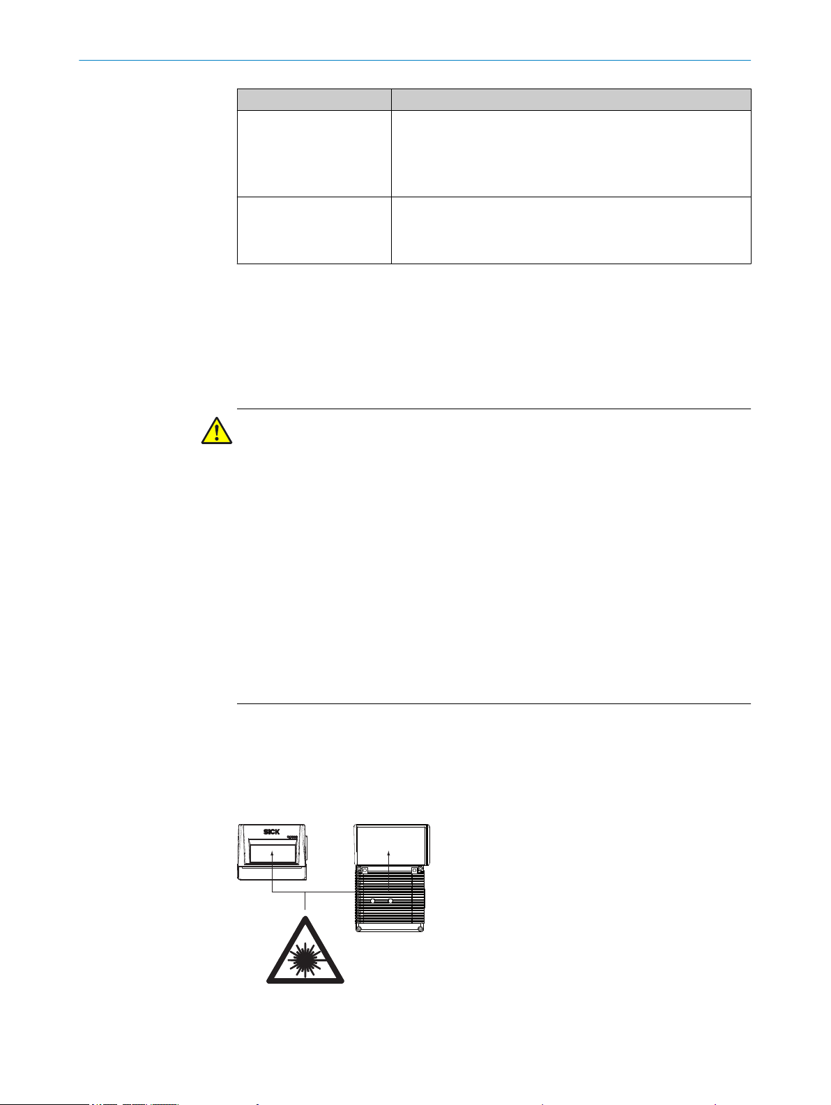
Laser class
Figure 1: Laser output aperture in the different designs
8014396/ZMG8/2017-07-04 | SICK O PE R AT I NG IN S TR U CT I ON S | CLV69x
Subject to change without notice
9
1 2
2 SAFETY INFORMATION
The device complies with laser class 2. The entire reading window is a laser output
aperture.
NOTE
No maintenance is required to ensure compliance with laser class 2.
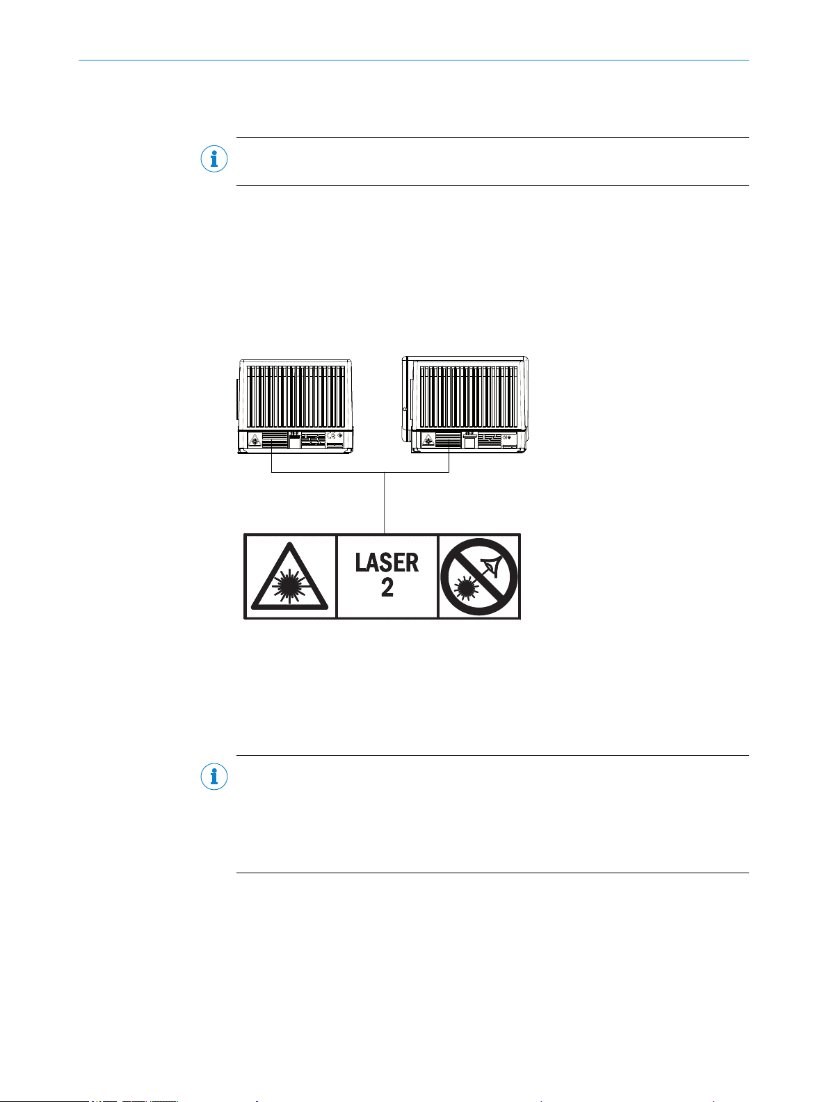
Warning symbol on the device
The colored laser warning label is fitted in combination with the type label on the rear of
the device.
In addition to other information, the type label of the device in use also contains the
laser output data. This consists of: Laser output power (maximum/average), wave‐
length or wavelength range, and pulse time duration. The data is located on the lower
section of the type label, see "Type label", page 12.
Figure 2: Example of a laser warning symbol on the device
Line scanner
1
Line scanner with oscillating mirror
2
What the laser warning label means: Laser radiation – Never look into the light beam –
Laser class 2
NOTE
Additional laser warning label
If the laser warning label applied to the device is concealed when the device is installed
into a machine or paneling, the laser beam outlet opening must be suitably labeled. For
this purpose, an additional warning label of the same type must be applied next to the
outlet opening.
Controlling the laser diode
When operating properly, the device only switches the laser diode on if there is an
object in the reading area, or if a reading is required (cyclic reading operation).
A laser timeout can switch off the laser diode automatically in this type of object trigger
control if the pulse has stopped for too long (e.g. the conveyor system has stopped). In
this case, the current internal reading interval of the device remains open.
Irrespective of the selected configuration type, the laser timeout can be set as follows:
10
O PE R AT I NG IN S TR U CT I ON S | CLV69x 8014396/ZMG8/2017-07-04 | SICK
Subject to change without notice

Using the SOPAS ET configuration software, on the Illumination Control device page
•
During GSD configuration with the “10_Object Trigger Ctrl” module (Profinet/Profi‐
•
bus)
In the default setting, laser timeout is deactivated.
The laser diode is permanently or repeatedly switched on in the following device sta‐
tuses:
■
In the “Percentage Evaluation” and “Auto Setup” operating modes (only used tem‐
porarily for configuration/diagnosis)
■
In reading operation in the PSDI types “Auto pulse” (adjustable duty cycle) or
“free.”
If timeout is activated, it will have no effect here.
2.8 Switching off the device
When switching off the device, at the most, the following data will be lost:
■
Application-specific parameter sets that were only temporarily stored in the device
■
Last reading result
■
Daily operating hours counter
SAFETY INFORMATION 2
2.9 Protection of the environment
During construction of the device, attention was paid to achieving the smallest environ‐
mental impact possible. Apart from the housing, the device contains no materials using
silicon.
2.10 Repairs
Repair work on the device may only be performed by qualified and authorized person‐
nel from SICK AG. Interruptions or modifications to the device by the customer will inva‐
lidate any warranty claims against SICK AG.
8014396/ZMG8/2017-07-04 | SICK O PE R AT I NG IN S TR U CT I ON S | CLV69x
Subject to change without notice
11

1443 0297
S/N:
DC 10...30V 5.0W
1
2
3
4
5
6
Manufactured:
MAC
D-79276 Reute
Made in Germany
λ = 655nm
Pmax=1.5mW
P<1.0mW average
Pulse duration <300µs
Imax=700mA
P/N: 1068608
3 PRODUCT DESCRIPTION
3 Product description
3.1 Product ID
3.1.1 Type label
The type label gives information for identification of the device. An existing UL certifica‐
tion can be found on the type label.
Figure 3: Type label design for the device
Type designation
1
Part number
2
Serial number
3
Laser output data
4
MAC address
5
Date of manufacture
6
3.1.2 Type code
12
O PE R AT I NG IN S TR U CT I ON S | CLV69x 8014396/ZMG8/2017-07-04 | SICK
CLV x y z - a b c d
1 2 3 4 5 6 7 8
Table 2: Type code
Position Description Characteristic
1 Code reader V-principle
2 – 3 Product family 69: CLV69x
4 Resolution 0: Standard density
5 Scanning method, reading window
6 Electrical connection 0: 60-pin system connection
7 Front screen material 0: Glass
8 Application (ambient temperature) 0: 0 °C ... +40 °C (without heating)
1)
2)
1: Low density
2: High density
0: Line scanner, reading window on front
1: Line scanner with oscillating mirror,
orientation
1)
reading window on side
9: Special connection
1: Plastic
1: –35 °C ... +35 °C (integrated heating)
Refers to the longitudinal axis of the device.
For available interfaces, see respective cloning plug (accessories)
2)
Subject to change without notice
NOTE
9
8
3
ß
9
2
ß
Line scanner Line scanner with oscillating mirror
à
à
4
4
5
5
3
172
7 8
6
6
â
á
0
á
á
[B] CAN 1
HOST/AUX/I/OEthernet
Not all combinations are possible according to the type code. The available device var‐
iants can be found online at:
www.sick.com/CLV69x
•
3.2 Product characteristics
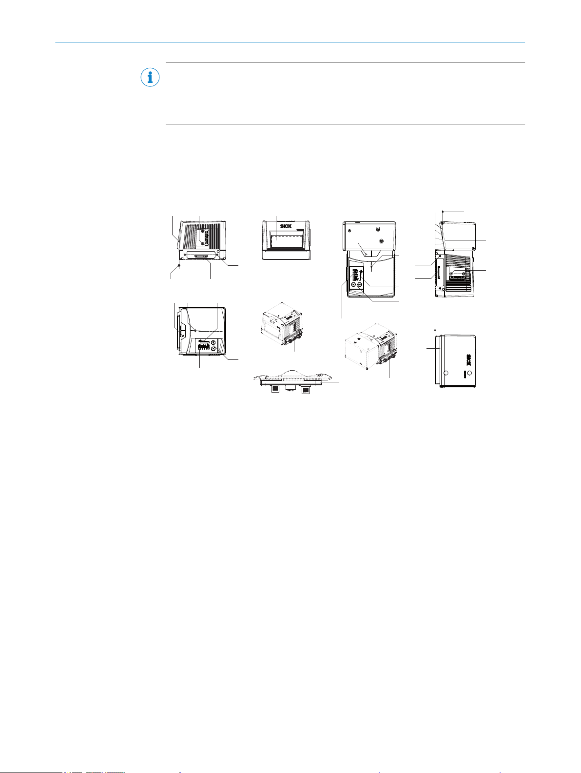
3.2.1 Device view
PRODUCT DESCRIPTION 3
Figure 4: Line scanner and line scanner with oscillating mirror
Mark for light emission level
1
Threaded mounting holes M6, 7 mm deep (2 x), for mounting the CLV69x
2
Threaded mounting holes M4, 10 mm deep (2 x), for mounting the cloning plug
3
60-pin male connector for connecting a cloning plug
4
Reference point for reading distance (housing edge) from CLV69x to object
5
Reading window
6
Mark for the direction of rotation of the mirror wheel and counting direction of the read
7
diagnostics date RA (Reading Angle)
Internal impact point: rotation point of the variable direction light beam
8
Bar graph
9
Function button (2 x)
ß
LED status display (6 x)
à
Monitored cloning plug
á
Vertical to the device longitudinal axis for oscillating mirror
â
8014396/ZMG8/2017-07-04 | SICK O PE R AT I NG IN S TR U CT I ON S | CLV69x
Subject to change without notice
13

3 PRODUCT DESCRIPTION
3.2.2 Product features and functions (overview)
Table 3: Overview of product features and functions of the device
Product feature/func‐
tion
Safety and ease of
use
Convenient operation/
configuration
Read operation modes
Read cycle
Bar code evaluation
Data processing
Data communication
Characteristic
•
•
•
•
•
•
•
•
•
•
•
•
•
•
•
•
•
•
•
•
•
•
•
•
•
•
•
•
•
•
•
Rugged, compact metal housing, CE marking
Laser Class 2, laser switches off if the output power is exceeded
Automatic self-test on system start
Diagnostic tools for system setup and (remote) system monitoring
Configurable output of reading diagnostic data in two reading
results formats
Operating data polling, in case of error, issue of error code if
required
Test string function (heartbeat) can be activated to signal that the
device is ready for operation
Password-protected configuration mode via SOPAS ET
Future-oriented by firmware update (FLASH PROM) via data inter‐
face
Future-oriented SOPAS ET configuration software
Low power consumption
Additional supply voltage range
Optional parameter cloning with external CMC600 parameter
memory module in the CDB/CDM connection module
Configuration (online/offline) via SOPAS ET configuration soft‐
ware
Configuration via GSD configuration (via CDF600-2xx)
Status displays via LEDs
Auto setup of the optical reading properties
Two pushbuttons on the device to call up preset functions without
connecting a computer
Buzzer, which can be switched off, to confirm the device function
Application and network setup assistant
Start/stop operation (one bar code bearing object per read pulse)
Tracking operation
Pulse sources for start: switching inputs, data interface (com‐
mand), auto pulse, free, CAN
Pulse sources for stop: read pulse source, switching inputs, data
interface (command), timer, condition
All current 1D bar code types
Max. number of bar codes: 50 per reading interval
Separation of identical codes of the same code type using the
read angle
Influencing the output of the reading data by event-dependent
evaluation conditions
Influencing the output string by filtering and output sorting
Host interface: two data output formats can be configured, can
be switched to various physical interfaces, parallel operation pos‐
sible
Aux interface: fixed data output format, can be switched to vari‐
ous physical interfaces
3.2.3 Operating principle
The device consists of a laser scanner (laser diode and optics), an electronics unit with
integrated decoder and interfaces (type-dependent) to industrial bus systems. The use
of various focusing settings, resolutions, scan processes, bus systems, mounting
options and optics enables use in most industrial applications. Interfaces to external
14
O PE R AT I NG IN S TR U CT I ON S | CLV69x 8014396/ZMG8/2017-07-04 | SICK
Subject to change without notice
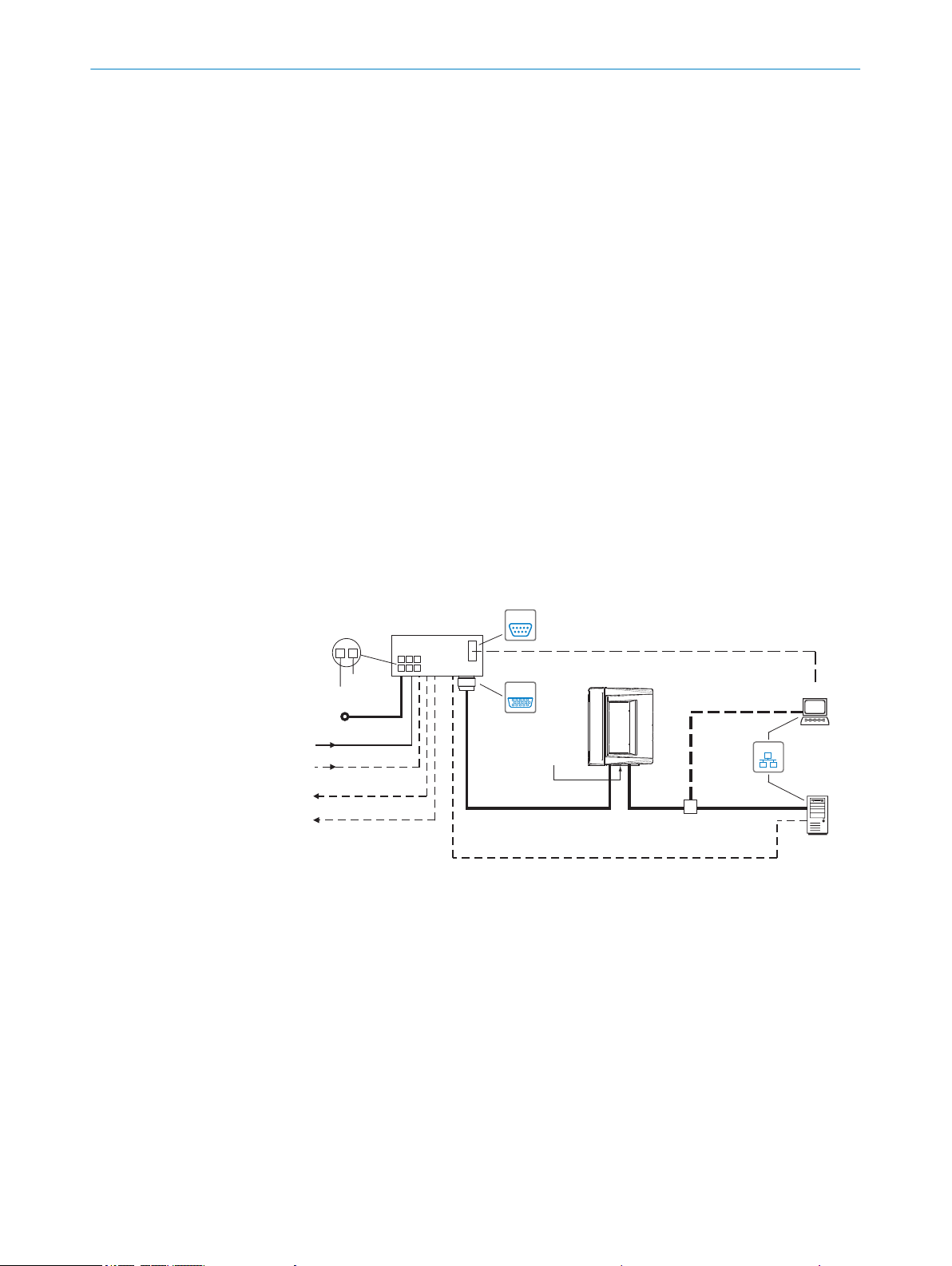
“Ethernet” (HOST 2)
Input 2
(e.g. encoder)
Input 1
(e.g. external read cycle)
Output 1
(e.g. LED)
Output 2
(e.g. LED)
CLV69x-xxx0
“Serial RS-232/RS-422/485” (HOST 1), alternative to Ethernet host port
CDM420-0006
SerialSerial
e.g. cable
no. 6034414 (2m)
e.g. cable
no. 2055419 (2m)
Configuration
Diagnostics
SOPASSOPAS
SerialSerial
“HOST/AUX/I/O”
(AUX 1, HOST 1)
...
...
1
2
DC 18V ... 30V
GND
HOST
PC
e.g. cable no. 2014054 (2m)
“Serial RS-232” (AUX 1), alternative to Ethernet AUX port
“Ethernet” (AUX 2)
DC 18V ... 30V
Switching inputs/outputs = digital
“Ethernet”
Reading result
Cloning plug
no. 2062452
EthernetEthernet
Further data
processing
PRODUCT DESCRIPTION 3
timers, such as photoelectric sensors or incremental encoders, enable reading pulses
independent of the control. The reading results are provided for further processing by
the data interfaces.
In principle, the codes can be recorded on any side on still or moving objects in a con‐
veyor system (single-side reading).
By combining several devices, it is possible to record several sides in one passage
(multi-side reading).
To record the codes, the device generates a scan line (line scanner).
Line scanner with oscillating mirror
The oscillating mirror also moves the scan line vertically to the scan direction from the
resting position to both sides with a low oscillation frequency. This means that the
device can also scan larger areas for bar codes.
The length of the scan line which can be used for evaluation (reading field height)
depends on the reading distance as a result of the V-shaped light emission.
The light pattern reflected by the bar code is recorded, processed and decoded. To con‐
trol this process, external sensors provide information about the reading pulse and the
conveyor speed (increment). The read results are released to the device's data interfa‐
ces and forwarded to a host/PC.
3.2.3.1 Object trigger control
8014396/ZMG8/2017-07-04 | SICK O PE R AT I NG IN S TR U CT I ON S | CLV69x
Subject to change without notice
Detailed wiring of the device and the connections to the host/PC and the external sen‐
sors are described in chapter Electrical installation.
Block diagrams
Figure 5: Facilities for connecting CLV69x, example
The device needs a suitable external signal (trigger source) as notification of an object
being in the reading field to start an object-related read process. As standard, the start
signal is issued via an external read cycle sensor (e.g. photoelectric sensor). As soon as
an object has passed the reading cycle sensor, a time window (“reading interval”) is
opened in the device for the reading process.
Alternatively, a command triggers the read process via a data interface or the
SICK SENSOR network. In auto pulse mode, the device internally generates the reading
gate itself with an adjustable clock ratio.
The read cycle can be terminated in various ways. In the event of external triggering,
this is carried out via the read cycle source or a command, or internally via a timer or an
evaluation condition that needs to be met.
15
1
2
3
Ready
Read Diagn
Ressult
Teach-in
Laser
Auto-Setup
Data
Adjusting
CAN
User defined
LINK TX
[%]
100
3 PRODUCT DESCRIPTION
NOTE
The SOPAS-ET configuration software can be used to configure the trigger source:
The auto focus function allows the device to conduct the distance detection for the
object without help from external sensors and to set the focus position independently.
In order to do this, the device measures the distance from the object in its field of
vision, uses this to create a distance profile internally and positions the focus on the
object.
The auto focus function works in the “Difference to background” mode. The device is
taught the distance profile of the background of its vision area without an object. Then
the device focuses on the object, which it detects by establishing the difference from
the background. The application is carried out e.g. with free vision of the object with
restriction from structures which permanently protrude into the read level. Only one
object with bar code(s) is in the reading field for each read cycle.
The distance profile of the background that is created can be displayed in the SOPAS ET
configuration software. The definition of the auto focus area is carried out by selecting
the aperture angle, the auto focus area and for line scanners with oscillating mirror also
by limiting the oscillation amplitude (the angle of deflection). It is possible to specify,
among other things, the park position (preferred position) of the focus position, from
which refocusing is carried out for each reading, for the device and a temporal and/or
spatial delay time (timeout/hysteresis).
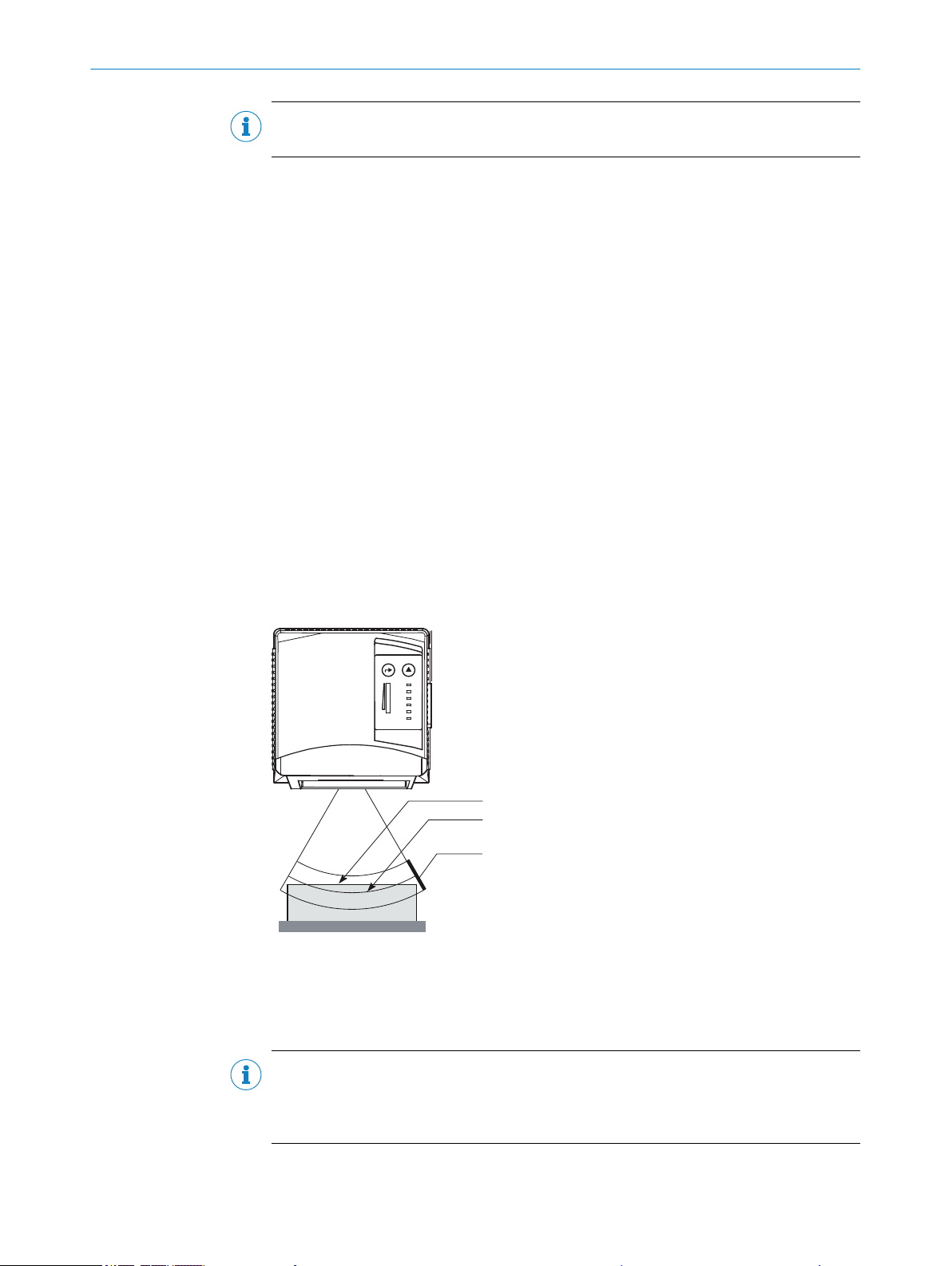
The focus position to be set via measurement can also have an additional offset
applied if necessary. This means that the depth of field, which runs radially in the direc‐
tion of the scan line and is caused by the V-principle of light beam deflection, can be
optimized for the object.
Figure 6: Auto-focus
Measured distance
1
Optimized focus position: measured distance plus offset for maximum
2
Depth of field (DOF)
3
NOTE
The auto focus function can be configured with the SOPAS-ET configuration software:
project tree, CLV6xx, parameters, read configuration, focus control, options tab, auto
focus parameters
16
O PE R AT I NG IN S TR U CT I ON S | CLV69x 8014396/ZMG8/2017-07-04 | SICK
Subject to change without notice
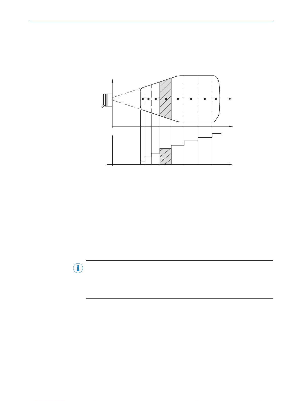
3.2.3.3 Switchable focus position
1 2 3 5 84 6 71
AK2
AK3
AK4
AK5
AK6
AK7
AK8
AK1
AK = distance configuration
Focus position
Reading distance
Reading distance
Reading
field
height
Focus
position
As an alternative to the auto focus function, the focus position can also be changed
dynamically and therefore cover a big read area.
A maximum of eight read areas can be defined internally as distance configuration for
this purpose and can be approached by the optics in any order in read mode.
PRODUCT DESCRIPTION 3
Figure 7: Focus switching - dividing the total read area into distance configurations
The switching of the focus is carried out by the changing object distance (e.g. during
reading from the top: object height detection).
Trigger sources for switching are:
– Signal on switching input “Sensor 2” for the max. 2-level switching
– Command to the host interface or the integrated timer (e.g. for search run) for the
max. 8-level switching
– Oscillating mirror turning points for deflection on both sides in the case of the line
scanner with oscillating mirror
The distance configurations are assigned to the switching order via a programmable
assignment table.
NOTE
The SOPAS-ET configuration software can be used to configure the focus position:
Project tree, CLV6xx, parameters, read configuration
•
Project tree, CLV6xx, parameters, read configuration, oscillating mirror
•
Project tree, CLV6xx, parameters, read configuration, focus control
•
3.2.3.4 Oscillating mirror control
In the case of a line scanner with oscillating mirror, the position of the scan line is influ‐
enced by the configuration of the oscillating mirror.
In addition to the “Park” (fixed, adjustable position of the scan line) or the continuous
oscillation (irrespective of the read cycle), optimized function processes related to the
read cycle are also possible in the controlled operation of oscillating mirror:
– n-times oscillation around an adjustable start position within the read cycle
– One-Shot: single deflection (approach and return) per read cycle from an adjusta‐
ble start position
8014396/ZMG8/2017-07-04 | SICK O PE R AT I NG IN S TR U CT I ON S | CLV69x
Subject to change without notice
17
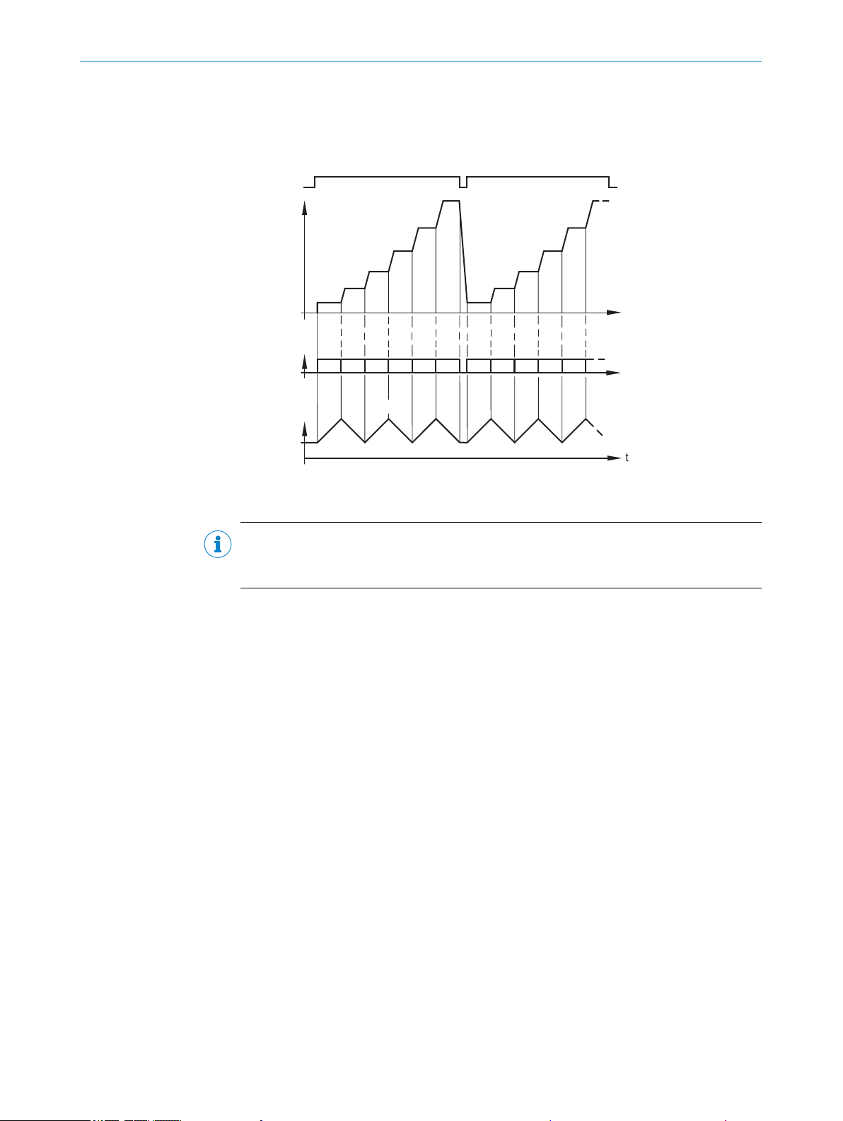
Read cycle
Focus
position
Angle of
deflection
‒φmax
+φmax
Timer
- or -
Oscillating
mirror
turning points
t
t
t1 t2 t3 t4 t5 t1 t2 t3 t4 t5t6
3 PRODUCT DESCRIPTION
In each oscillation mode, the deflection width can be set (amplitude) independently for
each of the deflection directions. Within the selected cycle duration of the entire vibra‐
tion process, the deflection speeds can be set in relation to each other for both deflec‐
tion directions.
Figure 8: Oscillating mirror - example for focus position control during the search run, here with 6
focus positions
NOTE
The SOPAS-ET configuration software can be used to configure the oscillation perform‐
ance and the position of the oscillating mirror.
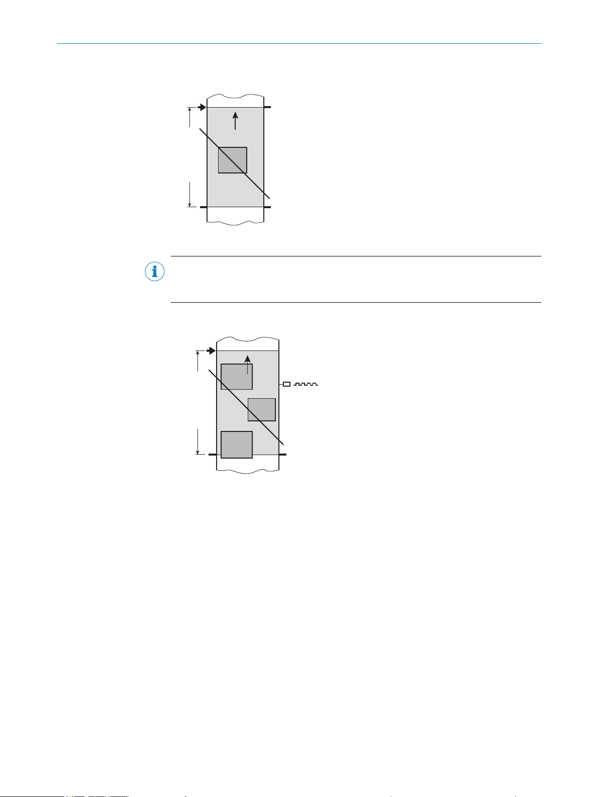
3.2.3.5 Reading operation mode
In “start/stop” operation, there is only ever one object in the reading field during the
reading process, i.e., all read codes can be clearly assigned to the object. As standard,
starting and stopping of the reading process are controlled by one or two read cycle
sensor(s) at the start and end of the reading field.
In this case, the distance between the read cycle sensors determines the size of the
reading field. The reading process can alternatively be controlled with command strings
via the data interface.
The output of the read results is either carried out at the end of the read cycle (the rear
edge of the object has left the end of the reading field) or even during the read cycle if
certain configurable conditions are met.
18
O PE R AT I NG IN S TR U CT I ON S | CLV69x 8014396/ZMG8/2017-07-04 | SICK
Subject to change without notice
Data
output
Trigger 2:
Stop
Trigger 1:
Start
Reading field
Start/stop operation
Tracking operation
Trigger 1:
Start
Reading field
Data
output
PRODUCT DESCRIPTION
Figure 9: Start/stop operating mode of the device in stand-alone operation
NOTE
The SOPAS ET configuration software can be used to configure the reading operation
mode.
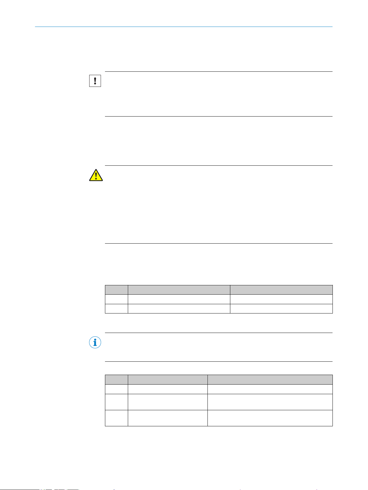
3
Figure 10: Tracking operating mode of the device in stand-alone operation
In the internal tracking operation, there are a maximum of 10 objects behind each
other in the reading field at the same time during the reading process.
As standard, the start of the reading process is controlled by a read cycle sensor at the
start of the reading field. The specification of the object release point defines the end.
This also defines the size of the resulting reading field.
In order to be able to track the transport of the objects in the reading field, a regular
cycle is required. This is generated by an external incremental encoder, which con‐
stantly provides at least one pulse per 1 mm movement in the conveyor direction. This
provides a clear temporal representation in the device of the route between the read
cycle sensor and object release point.
Jittering when the conveyor technology is starting up or in the event of slowing down
when there is a high load with lots of objects to convey is therefore also recorded. An
internal pulse generator in the device alternatively allows for operation at a conveyor
speed that is always constant.
A gap of at least 50 mm is necessary for clear separation of successive objects.
The issuing of the read result for an object is carried out after the rear edge of the
object passes the object release point. The reading process can alternatively be started
with a command string via the data interface.
8014396/ZMG8/2017-07-04 | SICK O PE R AT I NG IN S TR U CT I ON S | CLV69x
Subject to change without notice
19

4 TRANSPORT AND STORAGE
4 Transport and storage
4.1 Transport
For your own safety, please read and observe the following notes:
NOTICE
Damage to the product due to improper transport.
■
The device must be packaged for transport with protection against shock and
damp.
■
Recommendation: Use the original packaging as it provides the best protection.
■
Transport should be performed by trained specialist staff only.
■
The utmost care and attention is required at all times during unloading and trans‐
portation on company premises.
■
Note the symbols on the packaging.
■
Do not remove packaging until immediately before you start mounting.
4.2
Transport inspection
4.3 Storage
Immediately upon receipt in Goods-in, check the delivery for completeness and for any
damage that may have occurred in transit. In the case of transit damage that is visible
externally, proceed as follows:
■
Do not accept the delivery or only do so conditionally.
■
Note the scope of damage on the transport documents or on the transport compa‐
ny's delivery note.
■
File a complaint.
NOTE
Complaints regarding defects should be filed as soon as these are detected. Damage
claims are only valid before the applicable complaint deadlines.
Store the device under the following conditions:
■
Recommendation: Use the original packaging.
■
Do not store outdoors.
■
Store in a dry area that is protected from dust.
■
So that any residual damp can evaporate, do not package in airtight containers.
■
Do not expose to any aggressive substances.
■
Protect from sunlight.
■
Avoid mechanical shocks.
■
Storage temperature: see "Technical data", page 96.
■
Relative humidity: see "Technical data", page 96.
■
For storage periods of longer than 3 months, check the general condition of all
components and packaging on a regular basis.
20
O PE R AT I NG IN S TR U CT I ON S | CLV69x 8014396/ZMG8/2017-07-04 | SICK
Subject to change without notice
5 Mounting
5.1 Overview of mounting procedure
NOTICE
Special procedures are required during the mounting, installation and commissioning
of devices with integrated heating!
Observe the applicable notes; see "Mounting device", page 22, see "Notes on the
electrical installation", page 32 and see "Connecting the supply voltage", page 45.
Selecting and preparing the mounting location.
•
Mounting the device.
•
Align device towards object with bar code.
•
Connect device to data cable and supply cable.
•
Adjust the device.
•
WARNING
Risk of injury due to damage to the device
For reasons of safety, a device which is visibly damaged must not be operated or must
be immediately taken out of operation. Damage includes, for example:
MOUNTING 5
Housing: Cracked or broken
•
Reading window lens: Cracked or broken
•
Device with connector: Over-rotation of the connector, cracks, or being torn from
•
the housing
Device with fixed cable: Damage to the cable outlet or cable itself
•
5.2 Scope of delivery
The delivery of the device includes the following components:
Table 4: Scope of delivery
Item Component Comments
1 Device Depending on version
1 Printed safety note –
Additional scope of delivery
NOTE
The additional scope of delivery depends on the complete order/device variant. The
components are obligatory for operation and must be ordered separately.
Table 5: Additional scope of delivery
Piece Component Comments
1 Cloning plug Depending on selected version
1 Code-resistant connecting
1 Attachment kit Only in variants with integrated heating (included in
Only in variants with integrated heating
cables
the basic scope of delivery)
8014396/ZMG8/2017-07-04 | SICK O PE R AT I NG IN S TR U CT I ON S | CLV69x
Subject to change without notice
21
5 MOUNTING
5.3 Preparation for mounting
5.3.1 Mounting requirements
NOTICE
Radio interference may occur when the device is used in residential areas!
Only use the device in industrial environments (EN 61000-6-4).
■
Typical space requirement for device: See type-specific dimensional drawing and
reading field diagram.
■
Comply with technical data, such as the permitted ambient conditions for opera‐
tion of the device (e.g., temperature range, EMC interference emissions, ground
potential), see "Technical data", page 96.
■
To prevent condensation, avoid exposing the device to rapid changes in tempera‐
ture.
■
Protect the device from direct sunlight.
■
Device must only be mounted using the pairs of threaded mounting holes provided
for this purpose.
■
Shock and vibration-free mounting.
Equipment required
■
■
■
5.3.2 Mounting device
The device is mounted on the bracket using two M6 blind hole threads that are in pairs
on the narrow side of the device, see "Dimensional drawings", page 127.
The device can be installed using optional SICK brackets or customer-specific brackets.
SICK offers prefabricated brackets which are optimally suited for the mounting of the
device in a wide range of applications. See:
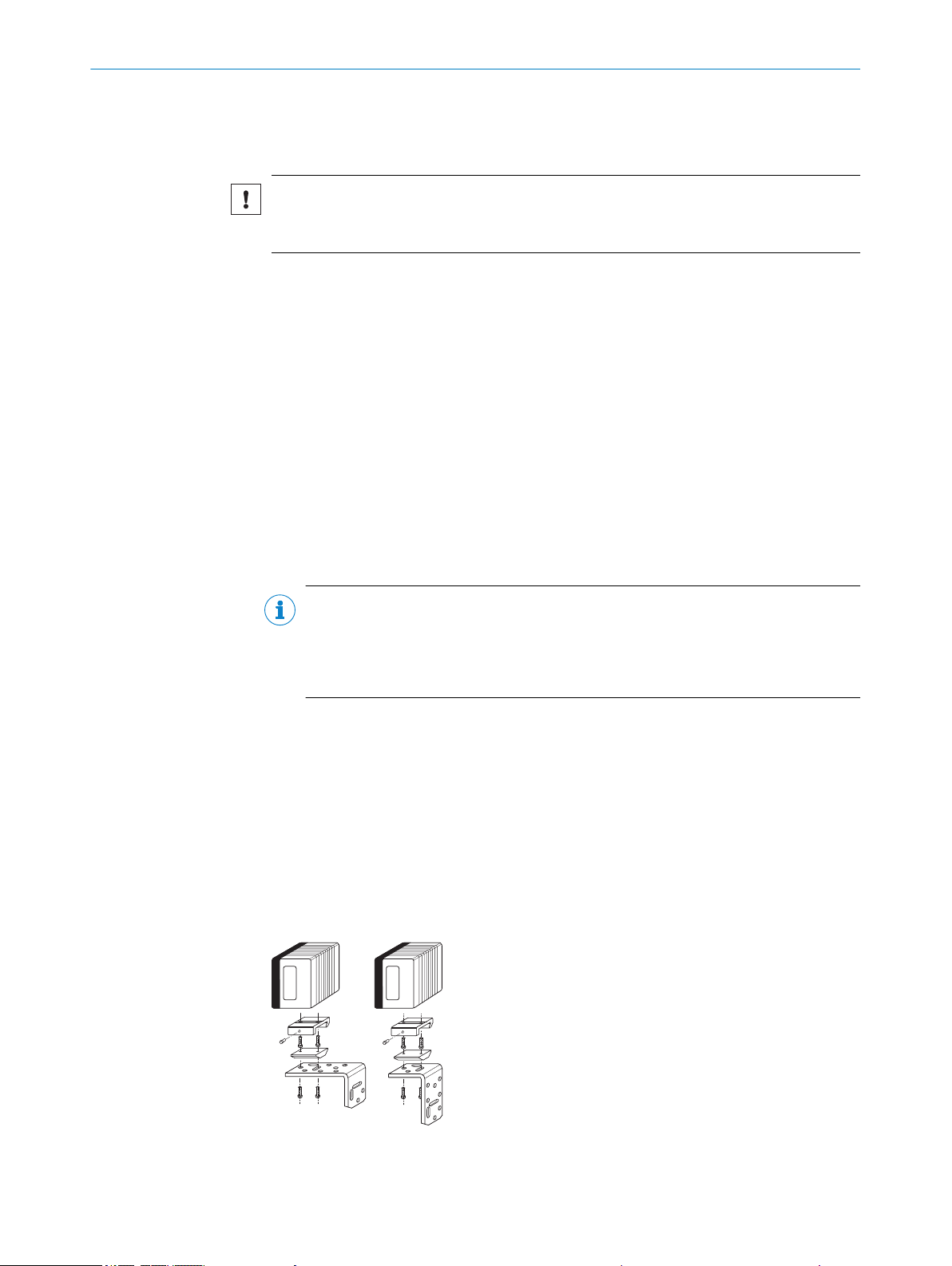
Example: The design of the bracket with adapter plate supports many different installa‐
tion variants, for example, as well as the alignment of the device in two axes.
Mounting device (bracket) with sufficient load-bearing capacity and suitable
dimensions for the device.
2 x M6 screws
NOTE
The screws are used for mounting the device on a mounting device supplied by the
user. Screw length is dependent on the mounting base (wall thickness of the
bracket). When using an optional SICK bracket, the screws for mounting the device
are included with delivery.
Tool and tape measure
22
Figure 11: Example of mounting a CLV69x with a quick clamping device and a mounting bracket
O PE R AT I NG IN S TR U CT I ON S | CLV69x 8014396/ZMG8/2017-07-04 | SICK
Subject to change without notice
CLV69x
Reading distance
Reading range
Line scanner
15°
15°
105°
Line scanner with oscillating mirror
MOUNTING 5
Devices with heating
User-supplied brackets
The brackets should meet the following requirements:
■
Stable mounting device
– Alignment of the device in the x and y axes can be adjusted.
– The mounting device must be able to bear the weight of the device and con‐
necting cables without shock.
■
Two M6 screws for mounting the device
– The screw length depends on the wall thickness of the mounting device.
– The maximum screw in depth in the device is 7 mm from the housing sur‐
face.
Addition for heated device variants
The scope of delivery for the heated devices includes an attachment kit for the thermal
decoupled mounting.
When preparing for mounting, the plastic plate of the attachment kit must be mounted
between the bracket and the device housing.
NOTE
The supplied counter-sunk screws replace the screws from mounting kit 1.
The supplied cylinder head screws replace the screws from mounting kit 2 or 3.
5.4 Mounting location
When selecting the mounting location, the following factors are significant:
Basic allocation of the scan line to the bar code
b
Reading distance to the bar code and aperture angle α
b
Angle alignment of the device
b
Avoidance of surface reflections
b
Count direction of the reading angle (position of the bar code along the scan line)
b
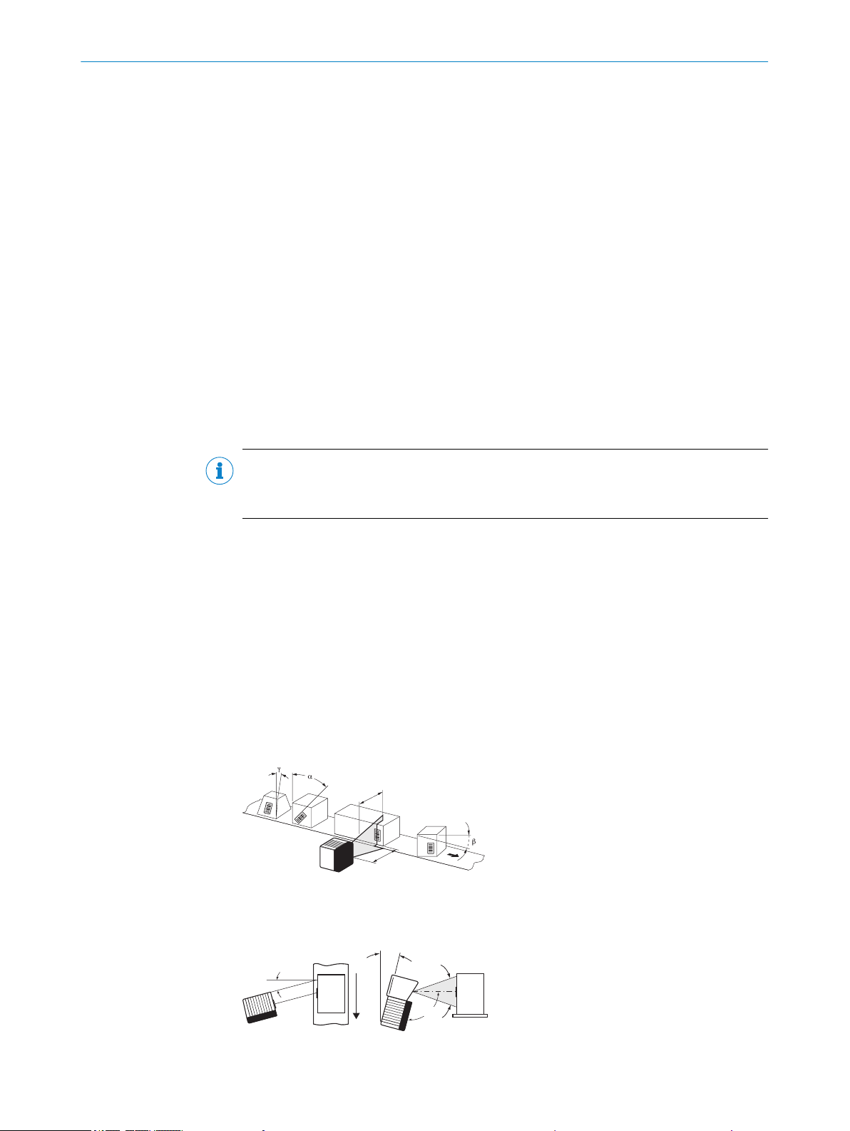
5.4.1 Basic allocation of the scan line to the bar code
The basic allocation of the scan line to the bar code on the object depends on the ver‐
sion of the device (line scanner or line scanner with oscillating mirror).
Figure 12: Allocation of the scan line to the bar code and conveyor direction
8014396/ZMG8/2017-07-04 | SICK O PE R AT I NG IN S TR U CT I ON S | CLV69x
Subject to change without notice
Figure 13: Line scanner (top view) and line scanner with oscillating mirror (side view)
23
105°
Line scanner Line scanner with oscillating mirror
Reading distance a
Reading distance a
β
α
γ
1
2
5 MOUNTING
5.4.2 Reading distance to the bar code and aperture angle α
The maximum distance from the reading window of the device to the bar code may not
exceed the design values for the device. Because of the V-shaped deflection of the
beams, the usable length of the scan line for evaluation (reading field height) depends
on the reading distance.
In the specification diagrams, the height of the reading field dependent on the reading
distance is shown for differing resolutions (module widths), see "Reading field condi‐
tions", page 98.
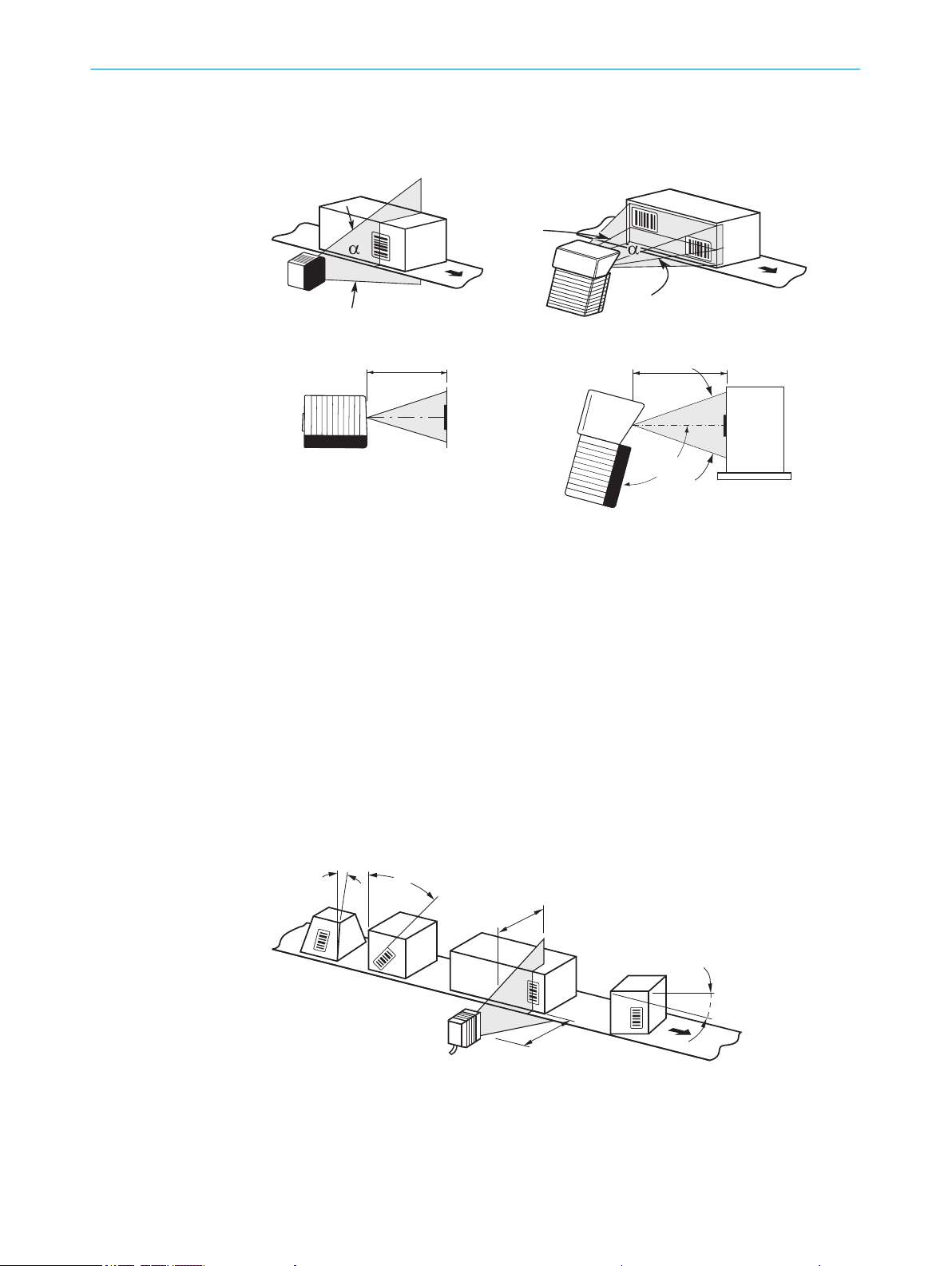
5.4.3 Angle alignment of the device
The optimum alignment of the device is achieved when the scan line crosses the
stripes of the bar code as close to a right angle as possible (tilt and inclination). Possi‐
ble reading angles that can arise between scan line and bar code at all three levels in
the area must be taken into account.
In order to prevent surface reflections, the angle of rotation must be approx. 15° out of
plumb to the bar code, see "Avoidance of surface reflections", page 25.
24
O PE R AT I NG IN S TR U CT I ON S | CLV69x 8014396/ZMG8/2017-07-04 | SICK
Figure 14: Line scanner: Read angle occurring between scanning line and bar code
Depth of field
1
2
Reading distance
Subject to change without notice
NOTE
Line scanner
15°
15°
105°
Line scanner with oscillating mirror
The specified maximum values can only be reached in optimum conditions. The actual
maximum depends on module width, code type, print contrast, ambient light, distance
and scanning frequency.
Table 6: Permitted read angle between scanning line and bar code
Angle Limit Value
Tilt α Max. 45°
Pitch β Max. 45°
Skew γ Max. 45°
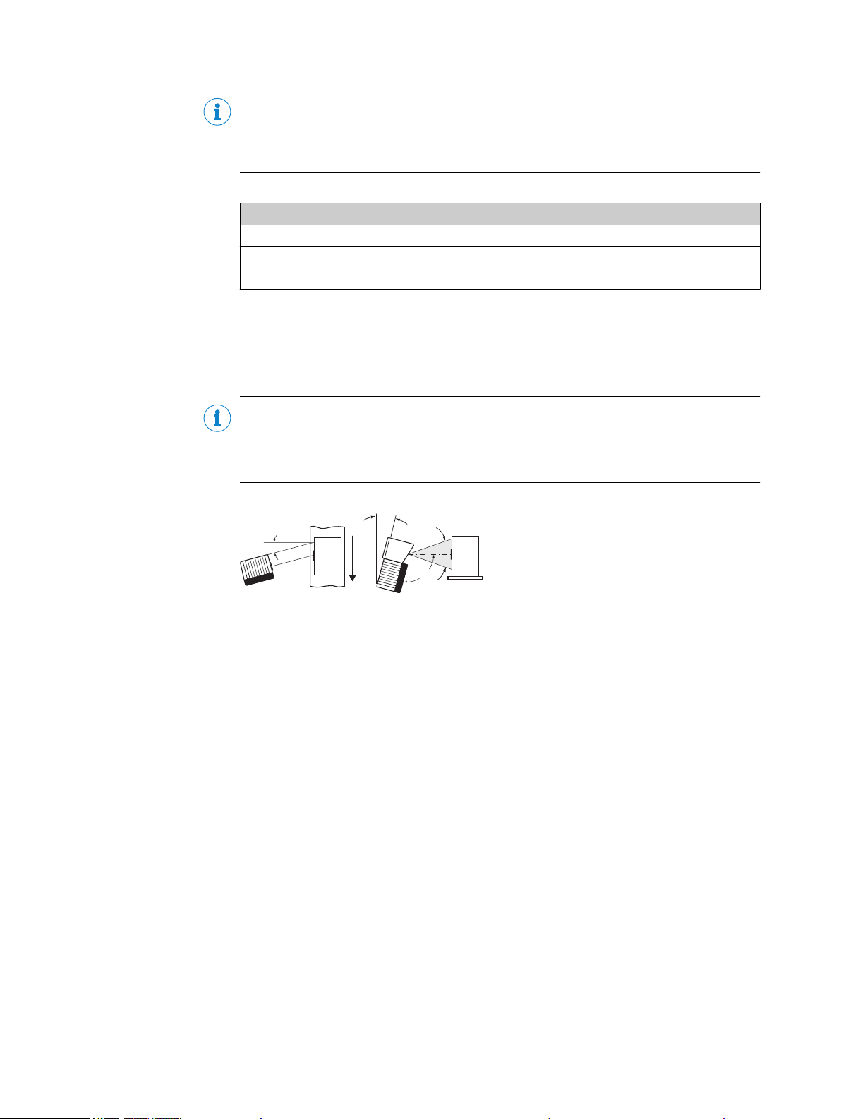
5.4.4 Avoidance of surface reflections
If the light of the scan line(s) hits the surface of the bar code precisely vertically, this
may cause interference when the light reflected back is received. To prevent this effect,
the device must be mounted so that the light emitted is tilted relative to the vertical.
NOTE
Optimum results are achieved when the scan line tilts approx. 15° from the vertical.
In devices with an oscillating mirror, these values relate to the central position of the
scan field.
MOUNTING 5
Figure 15: Avoiding surface reflections on the example line scanner – angle between light emit‐
ted and bar code (tilting away from vertical)
5.4.5 Count direction of the reading angle and the code angle
The device can scan and decode several bar codes at each reading.
At the same time, the location-specific reading diagnostics data are determined for
each of them.
■
The reading angle, starting from the reading window, at which the device detects
the bar code center on the red scanning line of the deflected scanning beam, can
be output as an RA (reading angle) value.
■
In addition, in the device with oscillating mirror, the angle of deflection of the scan
line under which the device detects the bar code on the red scan line can be
released as the CA (code angle) value.
By determining the RA/CA value, identical bar codes (code type, code length, and data
content) can be separated, and the bar code data can be assigned due to its position
on the object.
8014396/ZMG8/2017-07-04 | SICK O PE R AT I NG IN S TR U CT I ON S | CLV69x
Subject to change without notice
25
LF
LF
5 MOUNTING
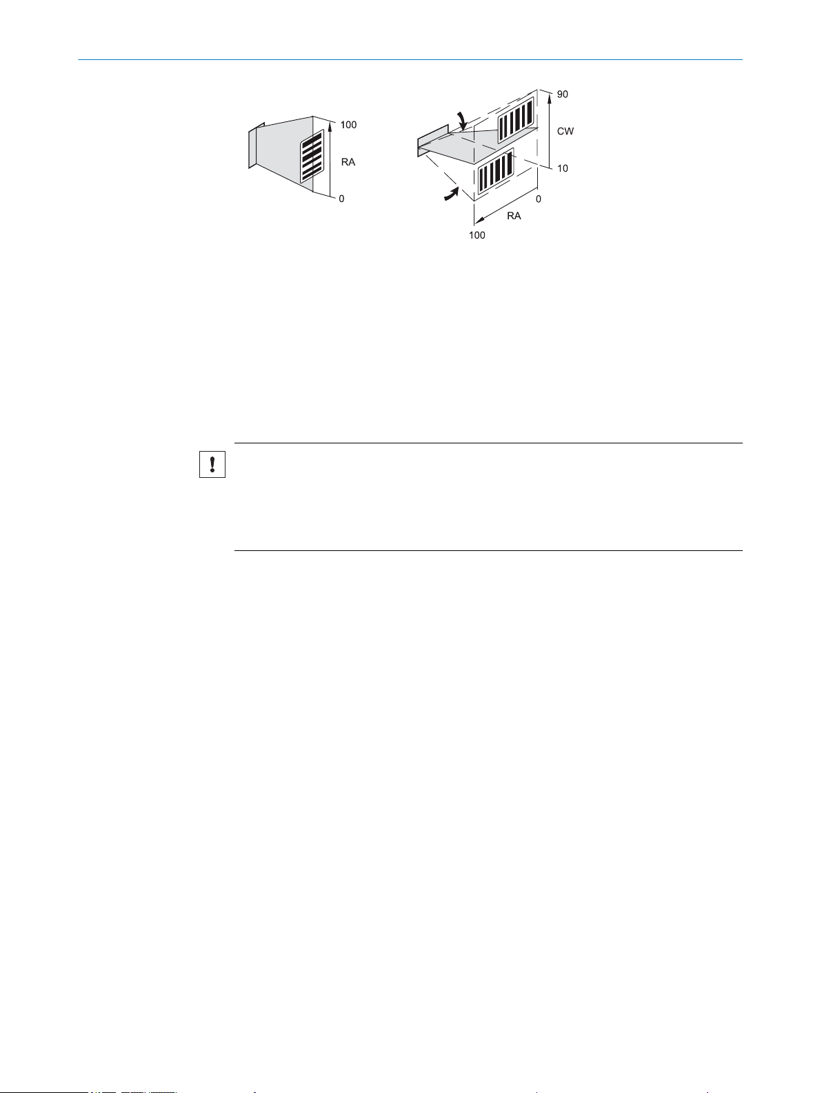
Figure 16: Example for count direction and RA/CA value determination in a line scanner (left)
and a line scanner with oscillating mirror (right)
RW Reading window
CA Code angle
RA Reading angle
5.5 Mounting the device
Mounting the device:
NOTICE
Risk of damaging the device!
Observe the maximum screw-in depth of the blind hole thread. Longer screws than
specified damage the device.
Use screws of suitable length.
b
1. Prepare the base for mounting the bracket of the device, see "Preparation for
mounting", page 22.
2. Place the object with the bar code in the view of the device in the position where
the reading is to take place (conveyor static).
3. Align the device with the bar code by eye. When doing so, be aware of the follow‐
ing:
– For a device with the reading window at the front, ensure that the rear side
with the laser warning label points in the direction of the observer and is
aligned as near as possible to being parallel to the bar code surface.
– For a device with the reading window at the side, ensure that the side panel
with the LEDs points in the direction of the observer and is aligned almost
parallel to the bar code surface.
– In a device with oscillating mirror, the wide side panel (rear of the oscillating
mirror) is almost parallel to the bar code surface.
– During reading, note the reading angle that occurs see "Angle alignment of
the device", page 24.
– If the position of the bar code within the scanning line is relevant for the eval‐
uation, bear in mind the count direction of the code position see "Count direc‐
tion of the reading angle and the code angle", page 25.
4. Mount the device bracket onto the base.
5. Screw screws through the bracket into the blind hole threads of the device and
slightly tighten.
6. Configure the device, see "Adjust the device", page 85.
5.6
26
Mounting with shock mounts (optional)
O PE R AT I NG IN S TR U CT I ON S | CLV69x 8014396/ZMG8/2017-07-04 | SICK
Subject to change without notice

MOUNTING
In application areas with heavy vibrations or subjected to shocks caused by oscillations,
jolting or abrupt changes in movement (e.g. when mounting onto a manned forklift
truck), mounting must be carried out using shock mounts. Suitable shock mounts are
available as accessories.
Appropriate brackets with shock absorbers can be found e.g. in the product catalog
under:
www.sick.com/clv69x
b
During mounting of a bracket with shock mount, it must be ensured that the holding
plate/the mounting bracket is screwed directly to the device and the shock attenuation
is applied as close as possible to the device. The shock mounts must always be
mounted horizontally over the scanner in order to achieve an optimum shock absorp‐
tion.
5
Figure 17: Angle bracket with shock mount
During mounting of an oscillating mirror device, the mounting bracket with integrated
vibration/shock attenuation is not mounted horizontally above the scanner, but verti‐
cally to the side on the device.
8014396/ZMG8/2017-07-04 | SICK O PE R AT I NG IN S TR U CT I ON S | CLV69x
Subject to change without notice
27
5 MOUNTING
Figure 18: Shock mount with ball joint mounting on oscillating mirror device
NOTICE
Risk of damaging the device!
In order to prevent damage during mounting and subsequent operation of the device,
the following points must be observed:
Use screws of suitable length.
b
Consider a travel of at least 25 mm in all axis directions of the device. This applies
b
in particular in the event of slanting installation.
Set the length of the feed lines according to the travel in order to ensure strain
b
relief.
28
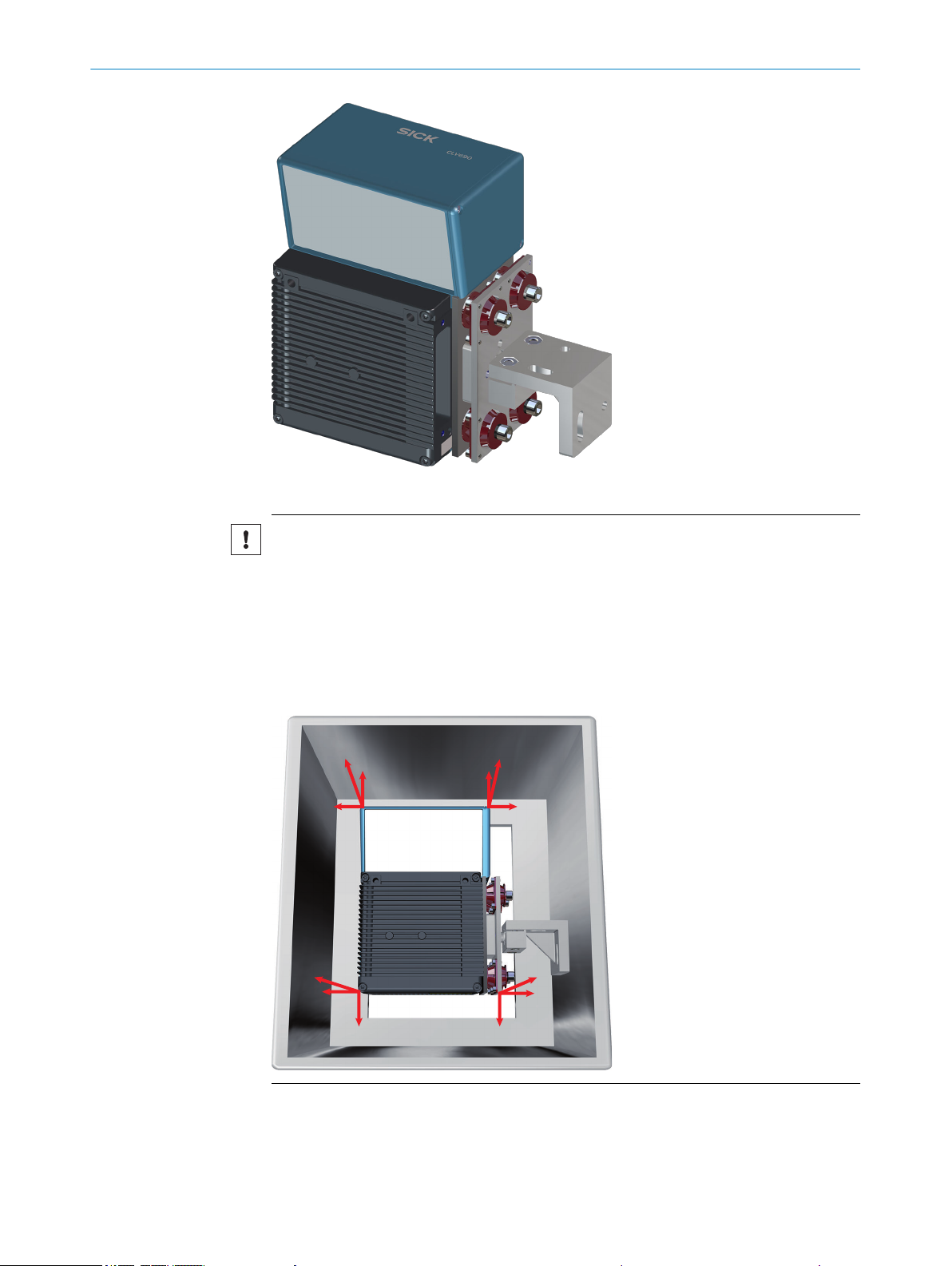
Permissible installation variants
Three installation variants are permitted:
1 Mounting of line scanner (horizontal reading line), mounting bracket with inte‐
grated vibration/shock attenuation
O PE R AT I NG IN S TR U CT I ON S | CLV69x 8014396/ZMG8/2017-07-04 | SICK
Subject to change without notice
MOUNTING 5
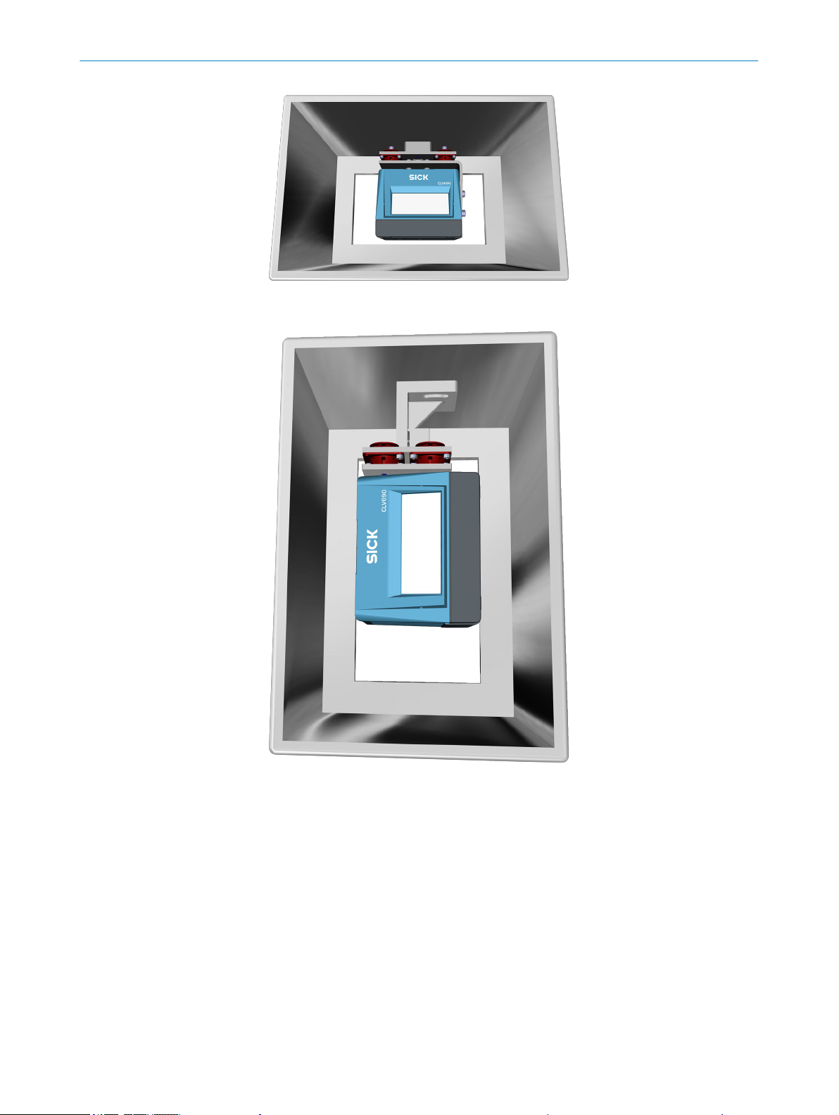
2 Mounting of line scanner (vertical reading line), ball joint bracket and mounting
bracket with integrated vibration/shock attenuation
8014396/ZMG8/2017-07-04 | SICK O PE R AT I NG IN S TR U CT I ON S | CLV69x
Subject to change without notice
29
5 MOUNTING
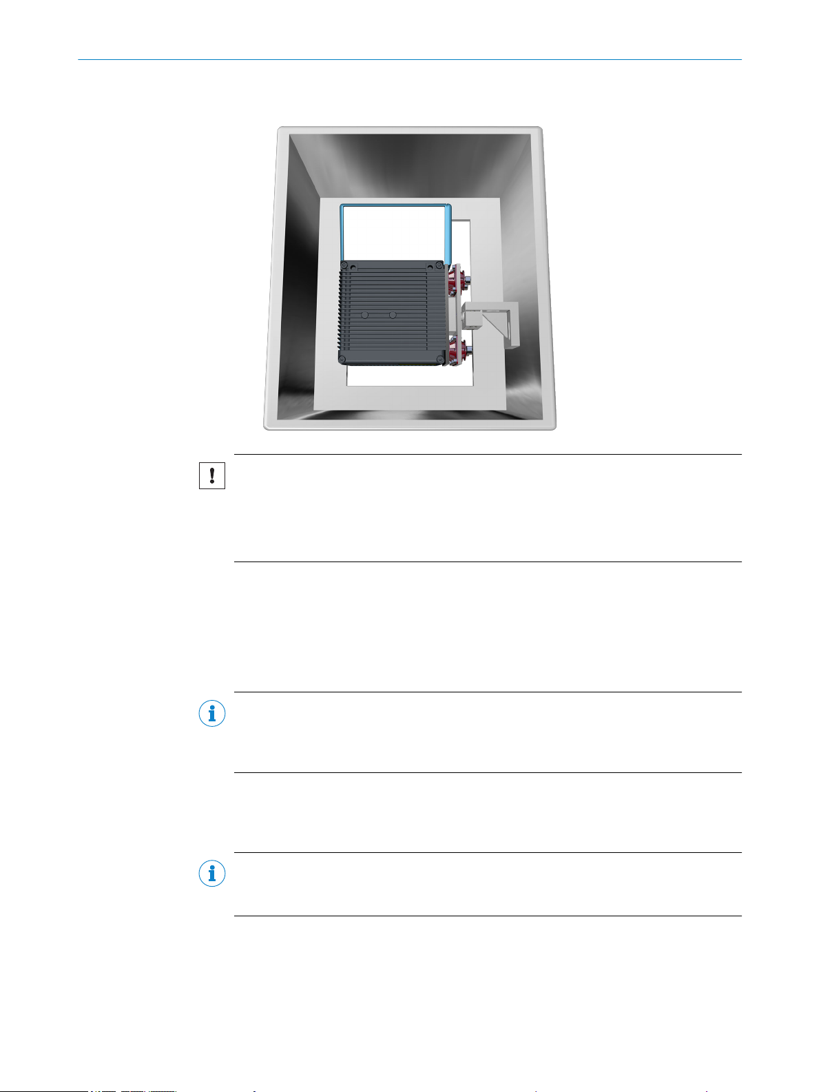
3 Mounting of oscillating mirror scanner (horizontal reading line), ball joint bracket
and mounting bracket with integrated vibration/shock attenuation
NOTICE
Risk of damaging the device
An incorrect installation position restricts the attenuation effect or amplifies strains that
occur.
Only carry out one of the three mounting variants listed.
•
5.7 Mounting of external components
5.7.1 Mounting the connection module
If the device activation is carried out via a connection module, then this must be
mounted near to the device.
NOTE
If the PC with the configuration software SOPAS ET accesses the AUX interface
(RS-232; 57.6 kBd) of the device via the connection module, then the connection mod‐
ule must be installed no more than a 3 m length of cable from the device.
1. Mount the connection module in the vicinity of the device.
2. Mount the connection module in such a way that the open module can be
accessed at all times.
NOTE
Detailed information on mounting and electrical installation can be found in the operat‐
ing instructions for the connection module.
5.7.2 Mount external read cycle sensor
If the device is triggered via an external read cycle sensor (photoelectric retro-reflective
sensor), then the sensor must be mounted in the vicinity of the device.
30
O PE R AT I NG IN S TR U CT I ON S | CLV69x 8014396/ZMG8/2017-07-04 | SICK
Subject to change without notice

NOTE
b
b < a
b
b < a
A large selection of photoelectric sensors and accessories (brackets, connecting
cables) can be found at www.sick.com.
Figure 19: Bar code at the end or start of the piece goods
The mounting location of the device is dependent on the distance a from the bar code
to the front object edge. Depending on the application, the device must be mounted so
that bar codes on objects of different sizes can be read in full during the time window
for evaluation (reading interval).
5.7.3 Mounting incremental encoder
MOUNTING 5
An incremental encoder is needed during the separation of bar codes of the same code
type and with identical contents.
The incremental pulses must originate from the area of the conveying line on which the
device is reading.
1. Mount suitable incremental encoders in the vicinity of the device.
Optimally, the incremental encoder is mounted against the running direction of the
conveying line in front of the device.
2. Create direct and secure contact with the drive technology and ensure that friction
wheel turns without slipping.
8014396/ZMG8/2017-07-04 | SICK O PE R AT I NG IN S TR U CT I ON S | CLV69x
Subject to change without notice
31

6 ELECTRICAL INSTALLATION
6 Electrical installation
6.1 Safety
6.1.1 Notes on the electrical installation
NOTICE
Equipment damage or unpredictable operation due to working with live parts.
Working with live parts may result in unpredictable operation.
■
Only carry out wiring work when the power is off.
■
Only connect and disconnect electrical connections when the power is off.
■
The electrical installation must only be performed by electrically qualified person‐
nel.
■
Standard safety requirements must be met when working on electrical systems.
■
Only switch on the supply voltage for the device when the connection tasks have
been completed and the wiring has been thoroughly checked.
■
When using extension cables with open ends, ensure that bare wire ends do not
come into contact with each other (risk of short-circuit when supply voltage is
switched on!). Wires must be appropriately insulated from each other.
■
Wire cross-sections in the supply cable from the customer's power system must be
selected in accordance with the applicable standards. When this is being done in
Germany, observe the following standards: DIN VDE 0100 (Part 430) and DIN VDE
0298 (Part 4) and/or DIN VDE 0891 (Part 1).
■
Only operate the device with LPS (limited power source) as per IEC 60950-1 or
NEC Class 2 power supply unit.
■
Circuits connected to the device must be designed as SELV circuits (SELV = Safety
Extra Low Voltage).
■
Protect the device with a separate fuse (type-specific max. 2 A (unheated) or 4 A
(heated)) at the start of the supply circuit.
NOTE
Layout of data cables
■
Use screened data cables with twisted-pair wires.
■
Implement the screening design correctly and completely.
■
To avoid interference, e.g. from switching power supplies, motors, clocked drives,
and contactors, always use cables and layouts that are suitable for EMC.
■
Do not lay cables over long distances in parallel with power supply cables and
motor cables in cable channels.
The IP enclosure rating for the device is only achieved under the following conditions:
■
The cables plugged into the connections are screwed tight.
■
Any electrical connections that are not being used must be fitted with protective
caps/plugs that are screwed tight (as in the delivery condition).
■
Any other possible coverings must be closed and lie flush on the device.
In the event of non-compliance, the IP enclosure rating will not apply for the device.
Additional notes on devices with integrated heating
When using heated devices, the following additional points must be noted:
■
Use cables suitable for the environmental conditions. In case of doubt, consult
SICK Service.
■
Amended supply voltage range: DC 21.6 V ... 28.8 V
32
O PE R AT I NG IN S TR U CT I ON S | CLV69x 8014396/ZMG8/2017-07-04 | SICK
Subject to change without notice
SICK
device
closed current loop with equalizing
currents via cable shield
grounding point 2
grounding point 1
grounding potential difference
e. g. PLC
e. g. sensor
I
U
= metal housing
= shielded electrical cable
ELECTRICAL INSTALLATION
■
Connection work only in the temperature range: 0 °C ... +50 °C
■
Only operate in idle state (no mounting or connection work).
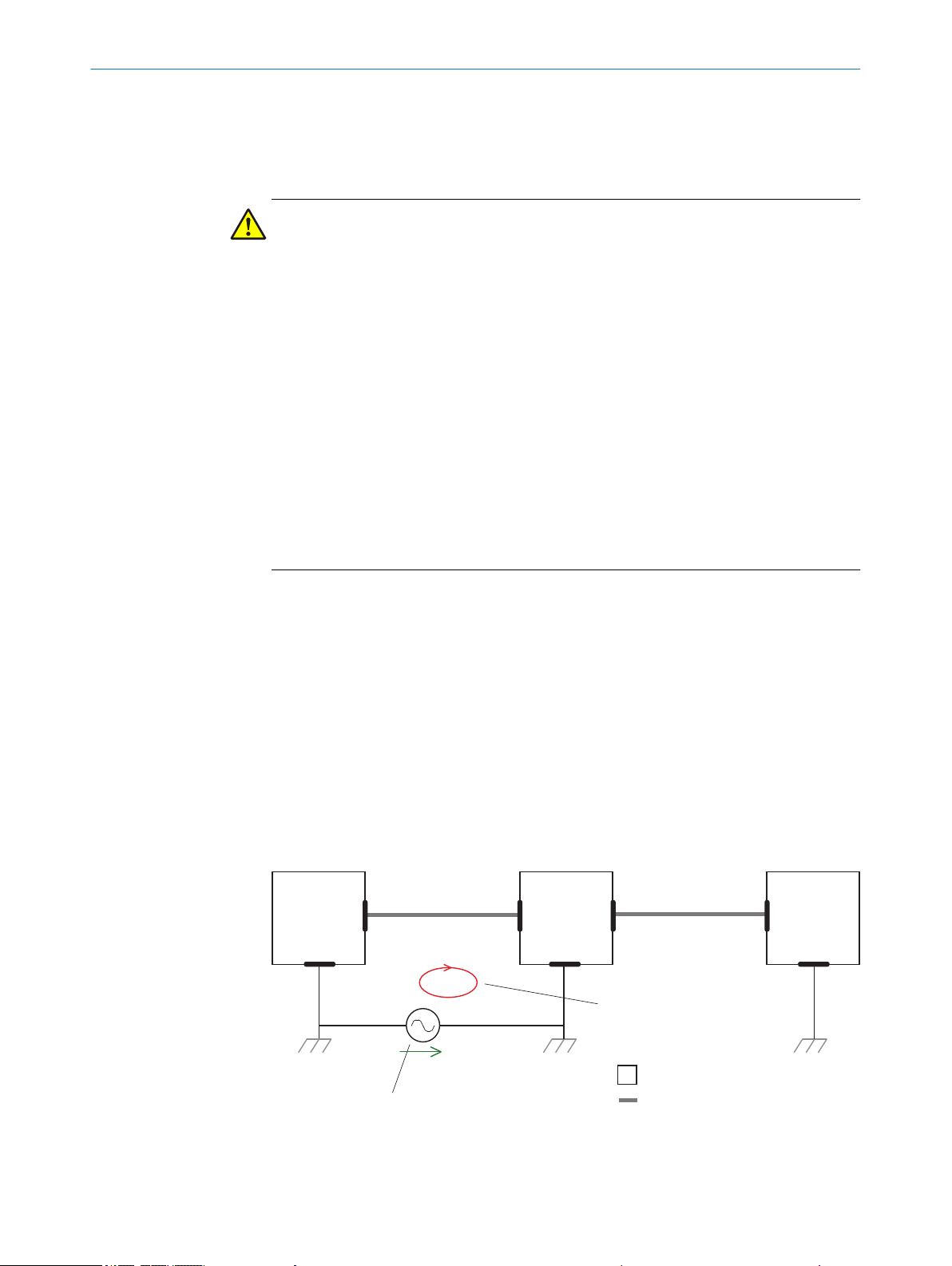
6.2 Prerequisites for the safe operation of the device in a system
WARNING
Risk of injury and damage caused by electrical current!
As a result of equipotential bonding currents between the device and other grounded
devices in the system, faulty grounding of the device can give rise to the following dan‐
gers and faults:
■
Metal housings are vulnerable to dangerous currents.
■
Devices will behave incorrectly or be destroyed.
■
Cable shielding will be damaged by overheating and cause cable fires.
Remedial measures
Only skilled electricians should be permitted to carry out work on the electrical sys‐
b
tem.
Ensure that the ground potential is the same at all grounding points.
b
If the cable insulation is damaged, disconnect the voltage supply immediately and
b
have the damage repaired.
Where local conditions are unfavorable and thus do not meet conditions for a safe
b
earthing method (same ground potential at all grounding points), take measures in
accordance with the following formats.
6
The device is designed and tested for electrical safety in accordance with EN 60950-1.
It is connected to the peripheral devices (power supply, any local reading pulse sen‐
sor(s), PLC) via shielded cables. The cable shield – for the data cable, for example –
rests against the metal housing of the device. The device can either be grounded
through the cable shield or through one of the threaded mounting holes.
If the peripheral devices have metal housings and if the cable shields also lie on their
housings, it is assumed that all devices involved in the installation have the same
ground potential.
This is achieved by complying with the following conditions:
■
Mounting the devices on conductive metal surfaces
■
Correct grounding of the devices/metal surfaces in the system.
■
If necessary: low-impedance and current-carrying equipotential bonding between
areas with different ground potentials
8014396/ZMG8/2017-07-04 | SICK O PE R AT I NG IN S TR U CT I ON S | CLV69x
Subject to change without notice
Figure 20: Occurrence of equipotential bonding currents in the system configuration
33
grounding point 1 grounding point 2
Electro-
optical
signal
isolator
Electro-
optical
signal
isolator
e. g. PLC
Power
supply
unit
SICK
device
shielded electrical cablemetal housing
fiber optic cable
ELECTRICAL INSTALLATION
6
If these conditions are not fulfilled, equipotential bonding currents can flow along the
cable shielding between the devices due to differing ground potentials; this can be dan‐
gerous. This is, for example, possible in cases where there are devices within a widely
distributed system covering several buildings.
Remedial measures
The most common solution to prevent equipotential bonding currents on cable shields
is to ensure low-impedance and current-carrying equipotential bonding. If this is not
possible, the following solution approaches serve as a suggestion.
NOTICE
We expressly advise against opening up the cable shields. This would mean that the
EMC limit values can no longer be complied with and that the safe operation of the
device data interfaces can no longer be guaranteed.
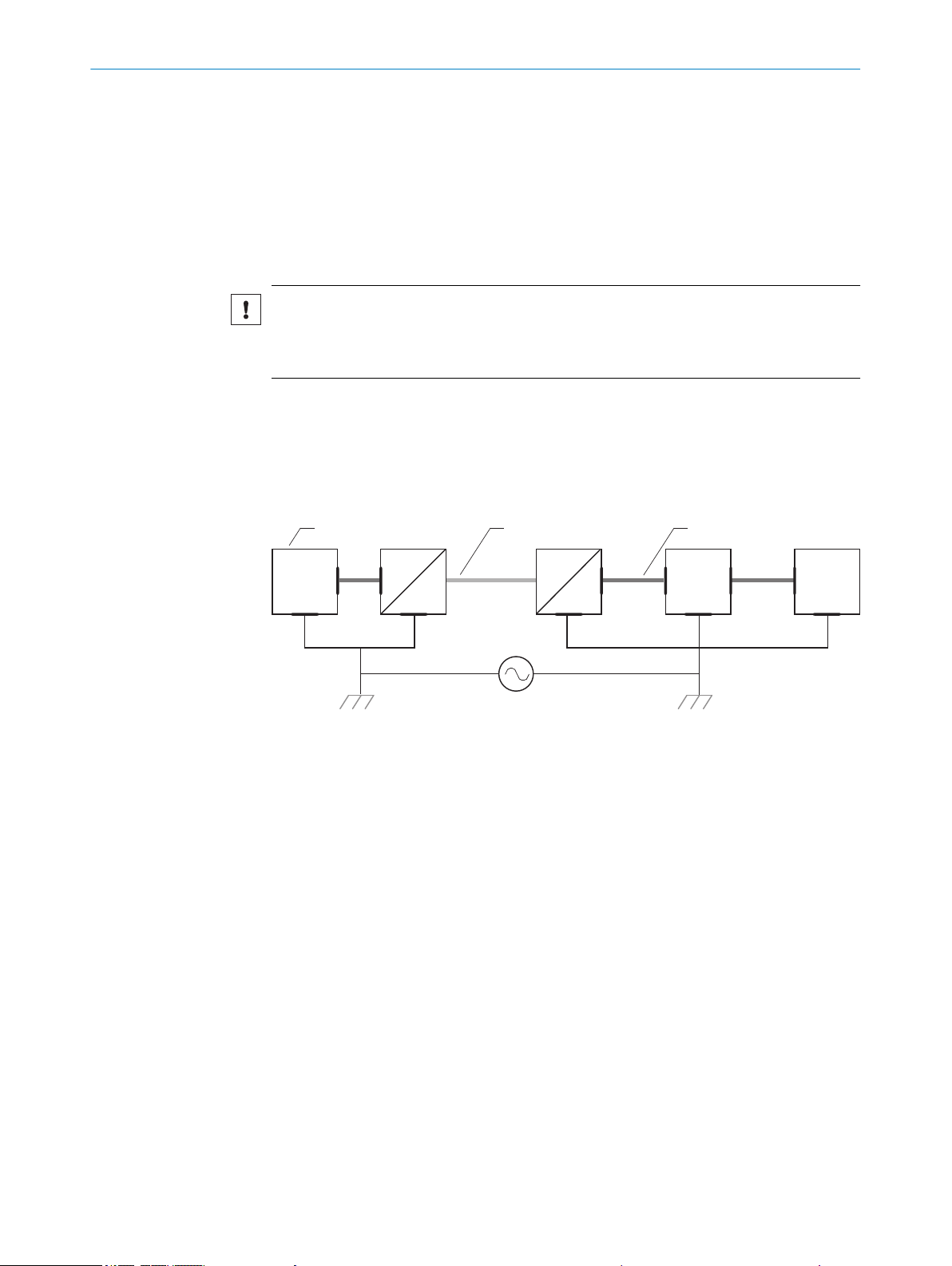
Measures for widely distributed system installations
On widely distributed system installations with correspondingly large potential differen‐
ces, the setting up of local islands and connecting them using commercially available
electro-optical signal isolators is recommended. This measure achieves a high degree
of resistance to electromagnetic interference while at the same time complying with all
the requirements of EN 60950-1.
Figure 21: Prevention of equipotential bonding currents in the system configuration by the use of
electro-optical signal isolators
The use of electro-optical signal isolators between the islands isolates the ground loop.
Within the islands, a stable equipotential bonding prevents equalizing currents on the
cable shields.
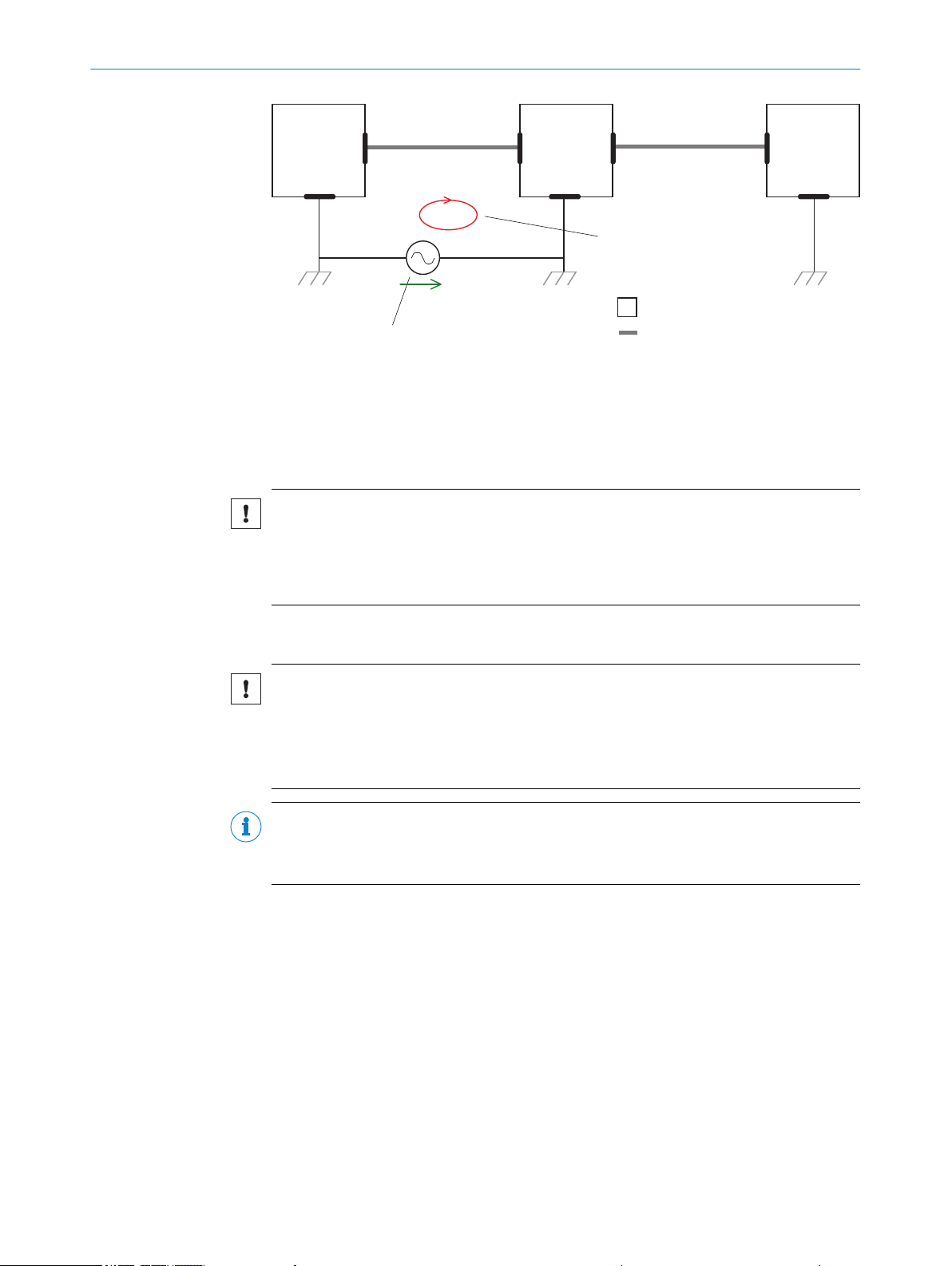
Measures for small system installations
For smaller installations with only slight potential differences, insulated mounting of the
device and of peripheral devices may be a sufficient solution.
34
O PE R AT I NG IN S TR U CT I ON S | CLV69x 8014396/ZMG8/2017-07-04 | SICK
Subject to change without notice
SICK
device
closed current loop with equalizing
currents via cable shield
grounding point 2
grounding point 1
grounding potential difference
e. g. PLC
e. g. sensor
I
U
= metal housing
= shielded electrical cable
ELECTRICAL INSTALLATION 6
Figure 22: Prevention of equipotential bonding currents in the system configuration by the insu‐
lated mounting of the device
Even in the event of large differences in the ground potential, ground loops are effec‐
tively prevented. As a result, equalizing currents can no longer flow via the cable shields
and metal housing.
NOTICE
The voltage supply for the device and the connected peripheral devices must also guar‐
antee the required level of insulation.
Under certain circumstances, a tangible potential can develop between the insulated
metal housings and the local ground potential.
6.3 Wiring notes
NOTICE
Faults due to incorrect wiring.
Incorrect wiring may result in operational faults.
■
For data transmission, use only screened cables with twisted-pair wires.
■
Follow the wiring notes precisely.
NOTE
Preassembled cables can be found online at:
www.sick.com/CLV69x
•
All electrical connections of the device are configured as M12 round connectors or as a
cable with D-Sub-HD male connector. The IP65 enclosure rating is only achieved with
screwed plug connectors or cover caps.
8014396/ZMG8/2017-07-04 | SICK O PE R AT I NG IN S TR U CT I ON S | CLV69x
Subject to change without notice
35

6 ELECTRICAL INSTALLATION
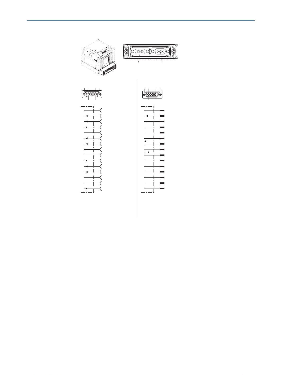
6.4 Pin allocation of the connections
6.4.1 Overview of the pin allocation for the cloning plug
Table 7: Pin allocations of the connections
Cloning plug
Variant A
No.: 2062450
D-sub variant Ethernet variant CAN 1 IN/OUT variant CAN 1/2 variant System variant 1 System variant 2
2 x D-Sub HD 3 x M12 3 x M12 3 x M12 3 x M12 3 x M12
Sensor 1 (Sensor3))1)Sensor 1
Sensor 2 (IN 03))
Sensor 3 (IN 13))
Sensor 4 (IN 23))
Sensor 5 (IN 33))
Sensor 6 (IN 43))
2)
Result 1
2)
Result 2
2)
Result 3
2)
Result 4
Serial AUX Serial AUX Serial AUX Serial AUX - -
Serial Host Serial Host - - - -
CAN 1 CAN 1 CAN 1 CAN 1 CAN 1 CAN 1
CAN 2 - - CAN 2 - CAN 2
- Ethernet - - Ethernet Ethernet
- - DC 24 V out
1)
Switching input
2)
Switching output
3)
Signal designation CLV480/490/CLX490
4)
Signals are not available on the 15-pin D-Sub HD male connector of all adapter cables
5)
For external fan
Variant B
No.: 2062452
1)
1)
Sensor 2
1)
- - - - -
1)
- Sensor 4 (IN 23))
1)
- - - - -
1)
- - - - -
Result 1
Result 2
Result 3
Result 4
1)
2)
2)
2)4)
2)4)
Variant C
No.: 2062453
Variant D
No.: 2062454
Variant E
No.: 2074708
- - - -
- - - -
1)
Sensor 4 (IN 23))
1)
- -
- - - -
- - - -
- - - -
- - - -
5)
DC 24 V out
5)
- -
Variant F
No.: 2074710
36
O PE R AT I NG IN S TR U CT I ON S | CLV69x 8014396/ZMG8/2017-07-04 | SICK
Subject to change without notice
61
10 5
1115
“HOST/AUX” connection, Vs, I
max out
= 1A
D-sub HD male
connector,
15-pin
CAN2_L
CAN1_L
CAN1_H
CAN2_H
TD+ (RS-422/485), HOST
Term (RS-422/485), HOST
TD– (RS-422/485),
TxD (RS-232), HOST
V
S
1)
TxD (RS-232), AUX
RxD (RS-232), AUX
RD+ (RS-422/485), HOST
GND
2)
RD– (RS-422/485),
RxD (RS-232), HOST
7
6
Reserved
3)
CAN_GND
4
3
2
1
5
8
9
10
11
12
13
14
15
Sensor 1 ... 6 = digital switching in puts
Result 1 ... 4 = digital switching ou tputs
1) Pin 1 male/female connector connecte d
2) Pin designation CLV480/490/CLX490
3) Pin 5 male/female connector connecte d
4) Do not use
1) Pin 1 male/female connector connecte d
2) Pin 5 male/female connector connecte d
3) Do not use
Connection
“HOST/AUX”
Connection
“I/O”
6
1
10
5
11
15
“I/O” connection, Vs, I
max in
= 1A
D-sub HD female
connector,
15-pin
Reserved
4)
Result 4
Result 3
Sensor 6 (IN 4 2))
Result 2
Result 1
Sensor 1 (Sensor2))
Sensor 2 (IN 0 2))
Sensor 4 (IN 2 2))
SensGND
GND
3)
7
6
Sensor 5 (IN 3 2))
Reserved
4)
4
3
2
1
5
8
9
10
11
12
13
14
15
V
S
1)
Sensor 3 (IN 12))
no. 2062450
ELECTRICAL INSTALLATION
Cloning plug A, D-Sub HD: Power/Serial Data/I/O/ CAN 1/2
6
8014396/ZMG8/2017-07-04 | SICK O PE R AT I NG IN S TR U CT I ON S | CLV69x
Subject to change without notice
Figure 23: Cloning plug A, D-Sub HD: Power/Serial Data/I/O/ CAN 1/2
37
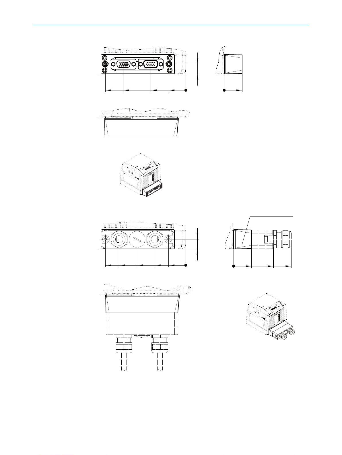
12
0
0
21
22
Cloning plug
43
77
99
All lengths in mm
View: cloning plug
[A]
I/0 HOST/AUX
Cloning plug
38
21
12
0
22
49
71
0
60
82
99
Cloning plug
All lengths in mm
View: cloning plug with modular hood
Modular hood with
connecting cables
(for CLV69x without
heating)
ELECTRICAL INSTALLATION
6
Figure 24: Cloning plug A, D-Sub HD: Power/Serial Data/I/O/ CAN 1/2
38
Figure 25: Cloning plug A, D-Sub HD: Power/Serial Data/I/O/ CAN 1/2
O PE R AT I NG IN S TR U CT I ON S | CLV69x 8014396/ZMG8/2017-07-04 | SICK
Subject to change without notice
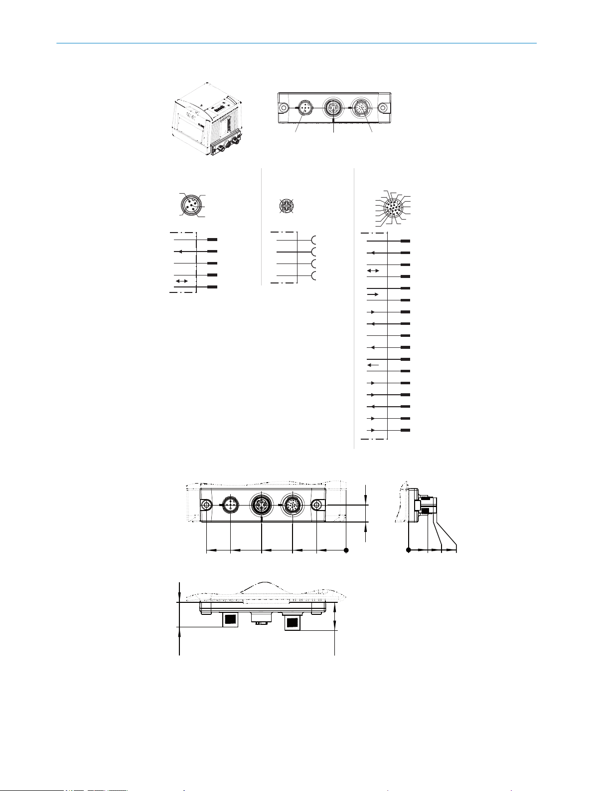
“CAN 1” connection,
VS, I
max in
= 4A
M12 male
connector,
5-pin,
A-coded
Shield
GND
V
S
1)2)
CAN1_L
CAN1_H
4
3
2
1
5
4
2
3
5
1
4
3
2
1
TD+
TD–
RD+
RD–
4
3
2
1
“Ethernet” connection
M12 female
connector,
4-pin,
D-coded
“HOST/AUX/I/0” connection,
Vs, I
max in
= 1.5A
M12 male
connector,
17-pin,
A-coded
CAN1_L
CAN1_H
TD+ (RS-422/485), HOST
TD– (RS-422/485),
TxD (RS-232), HOST
V
S
1)
TxD (RS-232), AUX
RxD (RS-232), AUX
RD+ (RS-422/485), HOST
GND
RD– (RS-422/485),
RxD (RS-232), HOST
Result 1
Result 3
Result 4
Result 2
7
6
Sensor 2
Sensor 1
SensGND
4
3
2
1
5
8
9
10
11
12
13
14
15
16
17
Connection
“Ethernet”
Connection
“CAN 1”
Connection
“HOST/AUX/I/O”
no. 2062452
17
16
10
11
12
15
14
6
5
4
13
7
8
9
1
2
3
1) For CLV69x-xxx0 (without heating):
both contacts suitable for connection
of the supply voltage.
2) For CLV69x-xxx1 (with heating):
only this contact suitable for connecti on
of the supply voltage.
Sensor 1 and 2 = digital switching in puts
Result 1 ... 4 = digital switching ou tputs
12
0
21
38
60
82
99
20
18
0
13.7
18
20
All lengths in mm
[B]
CAN 1 Etherne t HOST/AUX/I/O
ELECTRICAL INSTALLATION 6
Cloning plug B, M12: Power/Serial Data/I/O/Ethernet/CAN 1
8014396/ZMG8/2017-07-04 | SICK O PE R AT I NG IN S TR U CT I ON S | CLV69x
Subject to change without notice
Figure 26: Cloning plug B, M12: Power/Serial Data/I/O/Ethernet/CAN 1
Figure 27: Cloning plug B, M12: Power/Serial Data/I/O/Ethernet/CAN 1
39
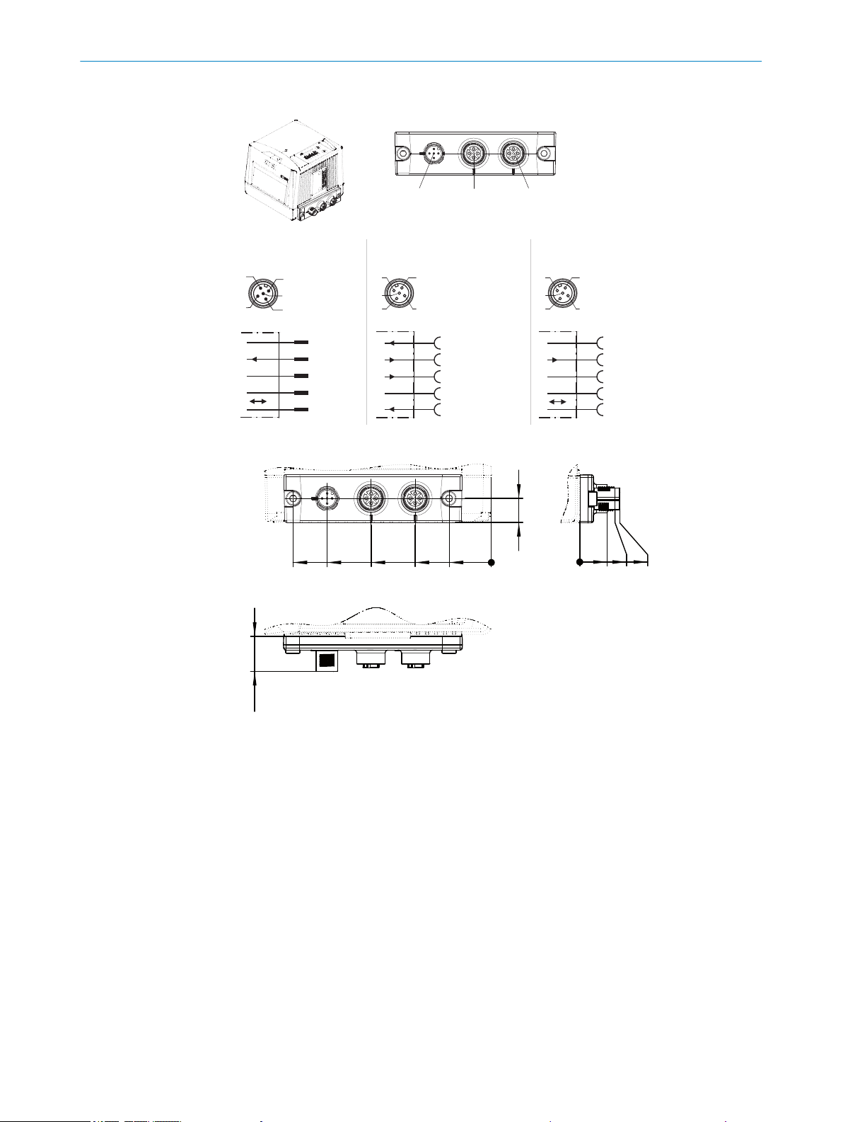
“CAN 1-IN” connection,
Vs, I
max in
= 4A
M12 male
connector,
5-pin,
A-coded
Shield
GND
V
s
CAN1_L
CAN1_H
4
3
2
1
5
4
2
3
5
1
“Blower/AUX” connection
Vs, I
max out
= 4A
M12 female
connector,
5-pin,
A-coded
Connection
“CAN 1-OUT”
Connection
“CAN 1-IN”
Connection
“Blower/AUX”
4
2
3
5
1
3
2
1
4
5
RxD (RS-232), AUX
TxD (RS-232), AUX
Vs OUT
Sensor 4 (IN 2*))
GND
*) pin designation CLV480/490/CLX490
3
2
1
4
5
“CAN 1-OUT” connection,
Vs, I
max out
= 4A
M12 female
connector,
5-pin,
A-coded
4
2
3
5
1
Shield
GND
V
s
CAN1_L
CAN1_H
no. 2062453
12
0
21
38
60
82
99
18
0
13.7
18
20
All lengths in mm
[C]
CAN 1-IN Blower/AUX CAN 1-OUT
6 ELECTRICAL INSTALLATION
Cloning plug C, M12: Power/Serial AUX/IO/CAN 1
Figure 28: Cloning plug C, M12: Power/Serial AUX/IO/CAN 1
40
Figure 29: Cloning plug C, M12: Power/Serial AUX/IO/CAN 1
O PE R AT I NG IN S TR U CT I ON S | CLV69x 8014396/ZMG8/2017-07-04 | SICK
Subject to change without notice
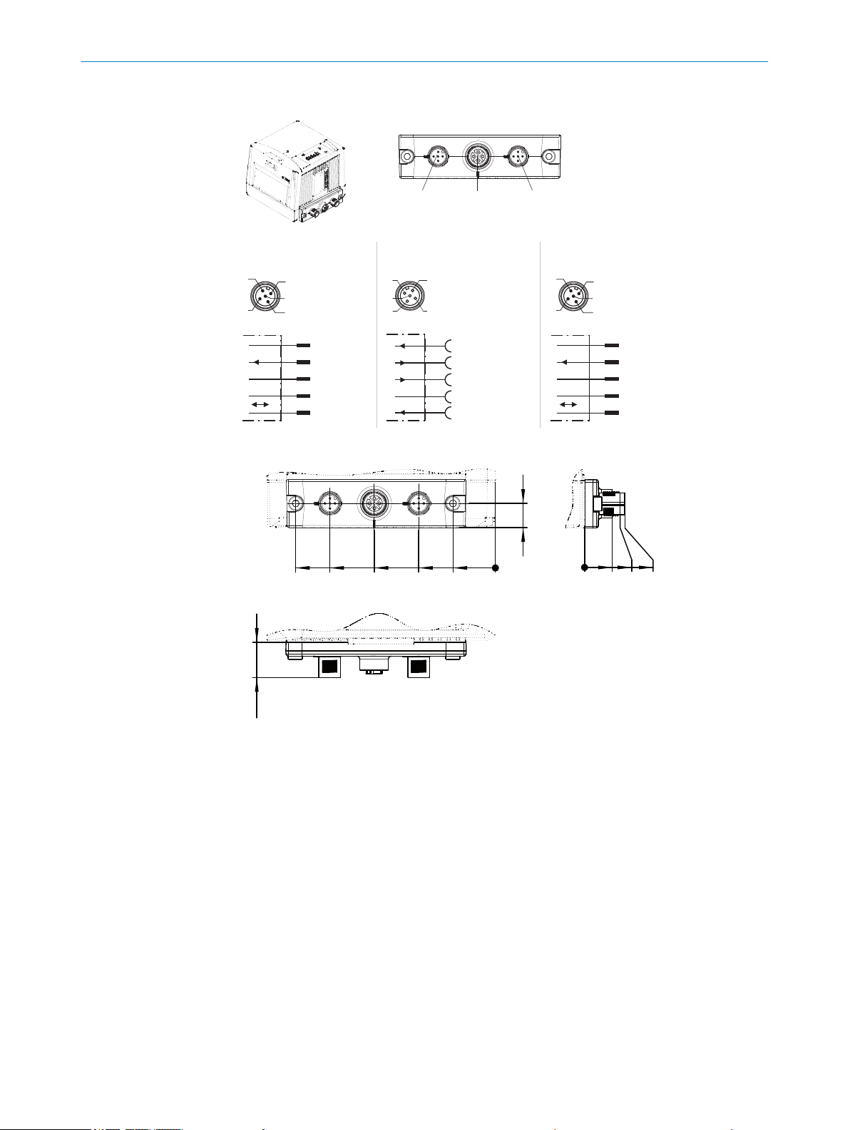
“CAN 1” connection,
UV, I
max in
= 4A
M12 male
connector,
5-pin,
A-coded
Shield
GND
Vs 1
CAN1_L
CAN1_H
4
3
2
1
5
4
2
3
5
1
“CAN 2” connection,
UV, I
max in
= 4A
M12 male
connector,
5-pin,
A-coded
Shield
GND
Vs 2
CAN2_L
CAN2_H
4
3
2
1
5
4
2
3
5
1
“Blower/AUX” connection
UV, I
max out
= 2 x LPS
M12 female
connector,
5-pin,
A-coded
Connection
“CAN 2”
Connection
“CAN 1”
Connection
“Blower/AUX”
4
2
3
5
1
3
2
1
4
5
RxD (RS-232), AUX
TxD (RS-232), AUX
Vs OUT fan
Sensor 4 (IN 2 *))
GND
*) pin designation CLV480/490/CLX490
no. 2062454
12
0
21
38
60
82
99
18
0
13.7
18
20
All lengths in mm
[D]
CAN 1 Blower/AUX CAN 2
ELECTRICAL INSTALLATION 6
Cloning plug D, M12: Power/Serial AUX/IO/CAN 1/2
Figure 30: Cloning plug D, M12: Power/Serial AUX/IO/CAN 1/2
Figure 31: Cloning plug D, M12: Power/Serial AUX/IO/CAN 1/2
8014396/ZMG8/2017-07-04 | SICK O PE R AT I NG IN S TR U CT I ON S | CLV69x
Subject to change without notice
41

“CAN 1-IN” connection,
VS, I
max in
= 4A
M12 male
connector,
5-pin,
A-coded
Shield
GND
V
s
CAN1_L
CAN1_H
4
3
2
1
5
4
2
3
5
1
“Ethernet” connection
Connection
“CAN 1-OUT”
Connection
“CAN 1-IN”
Connection
“Ethernet”
3
2
1
4
5
“CAN 1-OUT” connection,
VS, I
max out
= 4A
M12 female
connector,
5-pin,
A-coded
4
2
3
5
1
Shield
GND
V
s
CAN1_L
CAN1_H
no. 2074708
4
3
2
1
TD+
TD–
RD+
RD–
4
3
2
1
M12 female
connector,
4-pin,
D-coded
12
0
21
38
60
82
99
18
0
13.7
18
20
All lengths in mm
[E]
CAN 1-IN Ethernet CAN 1-OUT
6 ELECTRICAL INSTALLATION
Cloning plug E, M12: Power/Ethernet/CAN 1
Figure 32: Cloning plug E, M12: Power/Ethernet/CAN 1
42
Figure 33: Cloning plug E, M12: Power/Ethernet/CAN 1
O PE R AT I NG IN S TR U CT I ON S | CLV69x 8014396/ZMG8/2017-07-04 | SICK
Subject to change without notice
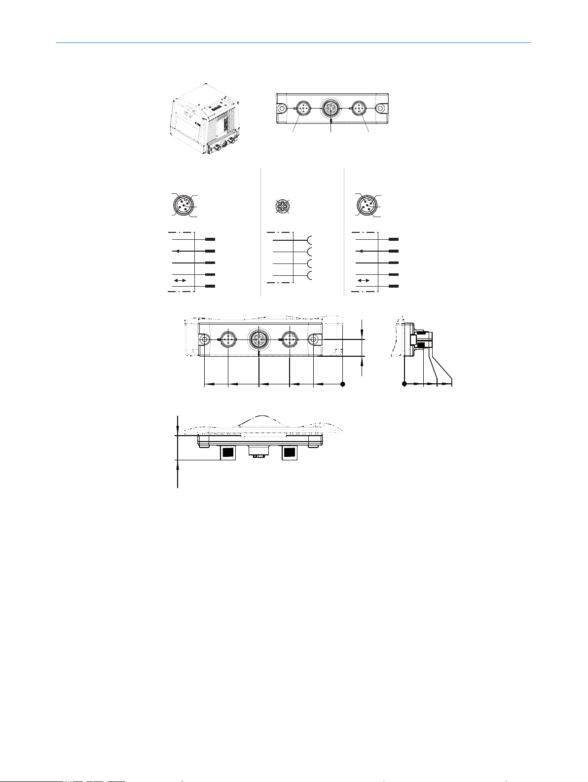
“CAN 1” connection,
VS, I
max in
= 4A
M12 male
connector,
5-pin,
A-coded
Shield
GND
VS 1
CAN1_L
CAN1_H
4
3
2
1
5
4
2
3
5
1
“CAN 2” connection,
VS, I
max in
= 4A
M12 male
connector,
5-pin,
A-coded
Shield
GND
VS 2
CAN2_L
CAN2_H
4
3
2
1
5
4
2
3
5
1
“Ethernet” connection
Connection
“CAN 2”
Connection
“CAN 1”
Connection
“Ethernet”
no. 2074710
4
3
2
1
TD+
TD–
RD+
RD–
4
3
2
1
M12 female
connector,
4-pin,
D-coded
12
0
21
38
60
82
99
18
0
13.7
18
20
All lengths in mm
[F]
CAN 1 Ethe rnet CAN 2
ELECTRICAL INSTALLATION 6
Cloning plug F, M12: Power/CAN 1/Ethernet/CAN 2
Figure 34: Cloning plug F, M12: Power/CAN 1/Ethernet/CAN 2
Figure 35: Cloning plug F, M12: Power/CAN 1/Ethernet/CAN 2
8014396/ZMG8/2017-07-04 | SICK O PE R AT I NG IN S TR U CT I ON S | CLV69x
Subject to change without notice
43

“Sensor 2”
“Host 1” (serial)
“Aux 1” (serial)
“Result 2”
“Result 1”
“CAN”
“Result 4”
“Sensor 1”
“Ext. input 2”
*)
“Ext. input 1”
*)
“Result 3”
“UV”
“Sensor 2”
“Sensor 1”
“AUX”
PLC
CAN bus
PLC
“Result 1”
“Result 2”
PLC
PLC
“Result 3”
“Result 4”
PLC
PLC
“Ext. output 1”
*)
“Ext. output 2”
*)
Connection module
CDB650-204
Other
functions
“HOST 1” (serial)
“AUX 1” (serial)
RS-232
CMC600
*) For the additional use of the external switching inputs and outputs, the optional CMC600 parameter memory module is required.
HOST/PLC
Further data
processing
Configuration
Diagnostics
*)
“Ethernet” (Host 2/Aux 2)
RS-232/422/485
Ethernet
“Host 2”
Ethernet
“Aux 2”
U
V
UV = DC 18 ... 30V (CLV69x-xxx0)
UV = DC 21.6 ... 28.8V (CLV69x-xxx1)
Decoder
Scanner
Interface
CLV69x-xxx0 (without heating)
CLV69x-xxx1 (with heating)
Cloning plug
no. 2062452
PC
Photoelectric
sensor
Read cycle end
(alternative)
Incremental
encoder
Route increment
Photoelectric
sensor
Read cycle
“UV”
“Sensor 2”
“Host 1” (serial)
“Aux 1” (serial)
“Result 2”
“Result 1”
“CAN”
“Sensor 2”
“Sensor 1”
“Ext. input 2”
*)
“Ext. input 1”
*)
“Sensor 1”
“AUX”
PLC
CAN bus
PLC
“Result 1”
“Result 2”
PLC
PLC
“Ext. output 1”
*)
“Ext. output 2”
*)
Connection module
CDM420-0006
Other
functions
“HOST 1” (serial)
“AUX 1” (serial)
RS-232
CMC600
*) For the additional use of the external switching inputs and outputs, the optional CMC600 parameter memory module is required.
HOST/PLC
Further data
processing
Configuration
Diagnostics
*)
“Ethernet” (Host 2/Aux 2)
RS-232/422/485
Ethernet
“Host 2”
Ethernet
“Aux 2”
U
V
UV = DC 18 ... 30V (CLV69x-xxx0)
UV = DC 21.6 ... 28.8V (CLV69x-xxx1)
Decoder
Scanner
Interface
CLV69x-xxx0 (without heating)
CLV69x-xxx1 (with heating)
Cloning plug
no. 2062452
PC
Photoelectric
sensor
Read cycle end
(alternative)
Incremental
encoder
Route increment
Photoelectric
sensor
Read cycle
ELECTRICAL INSTALLATION
6
6.5 Connection diagrams
CDB650-204
44
O PE R AT I NG IN S TR U CT I ON S | CLV69x 8014396/ZMG8/2017-07-04 | SICK
Figure 36: Connection of the device to the CDB650-204 connection module
CDM420-0006
Figure 37: Connection of the device to the CDM420-0006 connection module
Subject to change without notice

CDM490-0001
“Sensor 2 ... 6”
“Host 1” (serial)
“Aux 1” (serial)
“Result 1 ...4”
“CAN_2”
“CAN_1”
“UV”
“Sensor 1”
“Ext. input 2”
*)
“Ext. input 1”
*)
“Sensor 1 ... 6”
“AUX”
PLC
CAN bus 1
PLC
“Result 1”
“Result 2”
PLC
PLC
“Result 3”
“Result 4”
PLC
PLC
“Ext. output 1”
*)
“Ext. output 2”
*)
Connection module
CDM490-0001
Other
functions
CAN bus 2
“HOST 1” (serial)
“AUX 1” (serial)
RS-232
CMC600
*) For the additional use of the external switching inputs and outputs, the optional CMC600 parameter memory module is required.
Further data
processing
*)
RS-232/422/485
U
V
UV = DC 18 ... 30V (CLV69x-xxx0)
UV = DC 21.6 ... 28.8V (CLV69x-xxx1)
Decoder
Scanner
Interface
CLV69x-xxx0 (without heating)
CLV69x-xxx1 (with heating)
Cloning plug
no. 2062450
Configuration
Diagnostics
PC
HOST/PLC
Photoelectric
sensor
Read cycle end
(alternative)
Incremental
encoder
Route increment
Photoelectric
sensor
Read cycle
ELECTRICAL INSTALLATION 6
Figure 38: Connection of the device to the CDM490-0001 connection module
6.6
Wiring interfaces
6.6.1 Connecting the supply voltage
Connecting supply voltage to devices without heating
NOTICE
Devices with integrated heating may only be connected to the supply voltage via the 5pin M12 male connector “CAN 1” of the cloning plug.
In order to do this, the steps for the commissioning of devices with integrated heating
must be followed.
8014396/ZMG8/2017-07-04 | SICK O PE R AT I NG IN S TR U CT I ON S | CLV69x
Subject to change without notice
The device must be connected to a power supply unit with the following properties:
Supply voltage DC 24 V ± 20% (stabilized safety extra low voltage SELV as per cur‐
•
rently valid standards)
The electricity source must be able to release 144 W power or a maximum of 6 A
•
•
Connecting supply voltage to devices with integrated heating
NOTICE
When connecting the supply voltage, no further external components may be con‐
nected to the cloning plug (e.g. fan, PC using serial interface).
for a short time. The switching on current of the device is a maximum of 5.5 A for
1 to 2 ms (depending on the length of the supply cable).
Additional 0.5 W output power when using the optional CMC600 parameter mem‐
ory module in the corresponding connection modules
45

6 ELECTRICAL INSTALLATION
Supply voltage DC 21.6 V ... 28.8 V
•
The electricity source must be able to release 144 W power or a maximum of 6 A
•
for a short time. The switching on current of the device is a maximum of 5.5 A for
1 to 2 ms (depending on the length of the supply cable).
Additional 0.5 W output power when using the optional CMC600 parameter mem‐
•
ory module in the corresponding connection modules
1. Connect supply voltage to the 5-pin M12 male connector “CAN 1” on the cloning
plug with a suitable cable [SV = red (1), GND = blue (2), shield = gray].
2. Switch on the supply voltage and check the device start-up: device in operation?
(Status LEDs illuminate; mirror wheel activates.) A successfully passed test will
confirm that the supply line is connected correctly, and the GND wire in particular.
3. Connect connection cables to external components (e.g. fan, PC via serial inter‐
face, Ethernet) on the cloning plug.
Protecting the supply cables
To ensure protection against short-circuits and overload in the customer’s supply
cables, the conductor cross sections used must be appropriately selected and pro‐
tected.
The following standards must be observed in Germany:
DIN VDE 0100 (part 430)
•
DIN VDE 0298 (part 4) and/or DIN VDE 0891 (part 1)
•
The infeed of the supply voltage is carried out using a SICK connection module or the
customer's voltage supply.
6.6.2 Wiring data interfaces
Wiring Ethernet interface
1. Connect the device to the Ethernet connection of the PC via the adapter cable.
2. Set up communication via SOPAS ET configuration software.
NOTE
The Ethernet interface for the device has an Auto-MDIX function. This automatically
adjusts the transmission speed as well as any necessary crossover connections.
Wiring the serial data interfaces
The maximum data transmission rate for the serial interface depends on the cable
length and on the type of interface. The following recommendations apply:
Table 8: Data transmission rates
Interface type Data transmission rate Distance to the target computer
RS-232 Up to 19.2 kBd
RS-422/485
1)
For RS-422/485-suitable cable and corresponding cable termination as per specification
38.4 kBd ... 57.6 kBd
115.2 kBd … 500 kBd
1)
Up to 38.4 kBd
38.4 kBd ... 57.6 kBd
(host)
Max. 10 m
Max. 3 m
Max. 2 m
Max. 1200 m
Max. 500 m
46
O PE R AT I NG IN S TR U CT I ON S | CLV69x 8014396/ZMG8/2017-07-04 | SICK
Subject to change without notice

RS-232
!
"
§
Device 1 Host
TxD
RxD
GND
RxD
TxD
GND
RS-422
$
%
&
/
(
Device 1 Host
RD+
TD+
RD‒
TD‒
GND
TD+
RD+
TD‒
RD‒
GND
ELECTRICAL INSTALLATION 6
NOTICE
Risk of damage to the internal interface modules!
If the serial data interfaces are wired incorrectly, then electronic components in the
device could get damaged.
Observe the information on wiring.
b
Carefully check the wiring prior to switching on the device.
b
Figure 39: Internal circuitry for RS-232 and RS-485 data interfaces
Device
1
Pin assignment: See RS-232 pin assignment for the respective device
!...§
Pin assignment: See RS-422 pin assignment for the respective device
$...(
Termination of the RS-422 data interface
Termination of the data interface can be implemented in the connection module via
switches.
Additional information on this can be found in the operating instructions for the relevant
module.
6.6.3 Wiring the CAN interface
6.6.4 Wiring digital switching inputs
If the wiring of the CAN interface is carried out via a connection module, then the rele‐
vant operating instructions of the module used must be followed.
Physical switching inputs on the device
The physical switching inputs can be used for starting and/or ending the reading pulse
or for feeding an incremental signal.
Depending on the device, there are different number of switching inputs available on
8014396/ZMG8/2017-07-04 | SICK O PE R AT I NG IN S TR U CT I ON S | CLV69x
Subject to change without notice
the connections, see "Pin allocation of the connections", page 36.
Table 9: Characteristic data for the switching inputs
Switching behavior Power at the input starts the internal reading interval of the device
(default: active high, debounce: max. 30 ms (standard))
47
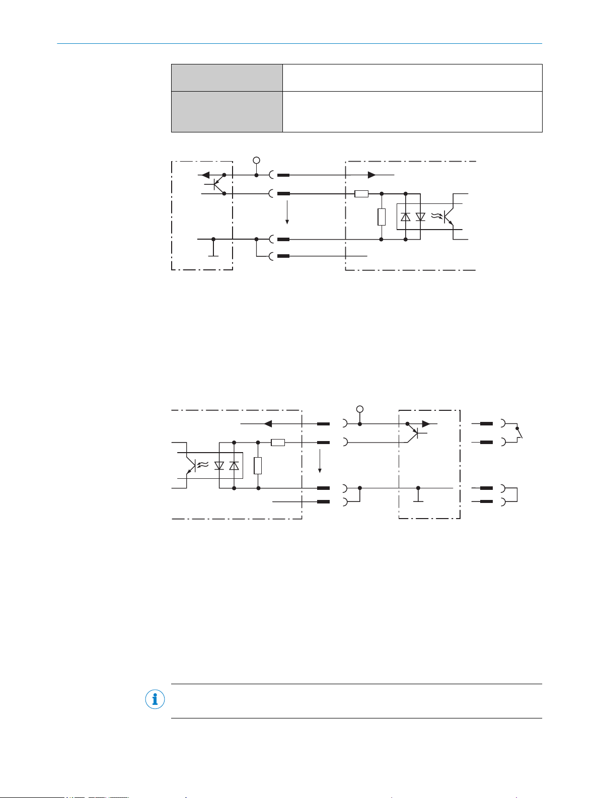
Signal 3
3.32K
6.64K
"
§
$
Sensor GND
VS 2
V
S
V
S
V
in
5
!
PNP sensor 1
GND
Switching input 4
GND
V
S
SwitchPNP sensorSwitching input
Signal
3.32K
6.64K
1
2
3
4
1
2
3
4
Sensor GND
U
V
U
V
U
V
U
e
GND
GND
6 ELECTRICAL INSTALLATION
Properties Opto-decoupled
Electrical values The electrical values are identical for all switching inputs.
Figure 40: Wiring of a switching input with external PNP sensor
PNP sensor
1
Supply voltage V
2
Input signal
3
Switching input (“Sensor 1” or “Sensor 2”)
4
Input voltage V
5
For pin assignment, see respective device
!...$
Reverse polarity protected
Low: |Vin| ≤ 2 V; |Iin| ≤ 0.3 mA
High: 6 V ≤ |Vin| ≤ 32 V; 0.7 mA ≤ |Iin| ≤ 5 mA
S
in
48
Figure 41: Wiring of a switching input with external, triggered PNP sensor
Supply voltage U
1
Signal line (e.g. “Sensor 2”)
2
SensGND
3
GND
4
s
Extension: additional logical switching inputs in the device in the case of physical
“external” switching inputs on the optional connection module
Thanks to the optional CMC600 parameter memory module, the two external switching
inputs “External input 1” and “External input 2” on the relevant terminals in the connec‐
tion module are additionally available.
O PE R AT I NG IN S TR U CT I ON S | CLV69x 8014396/ZMG8/2017-07-04 | SICK
NOTE
These two external switching inputs are not suitable for time-critical applications.
If the wiring of the inputs is carried out via a connection module, then the relevant oper‐
ating instructions for the module must be followed.
Subject to change without notice
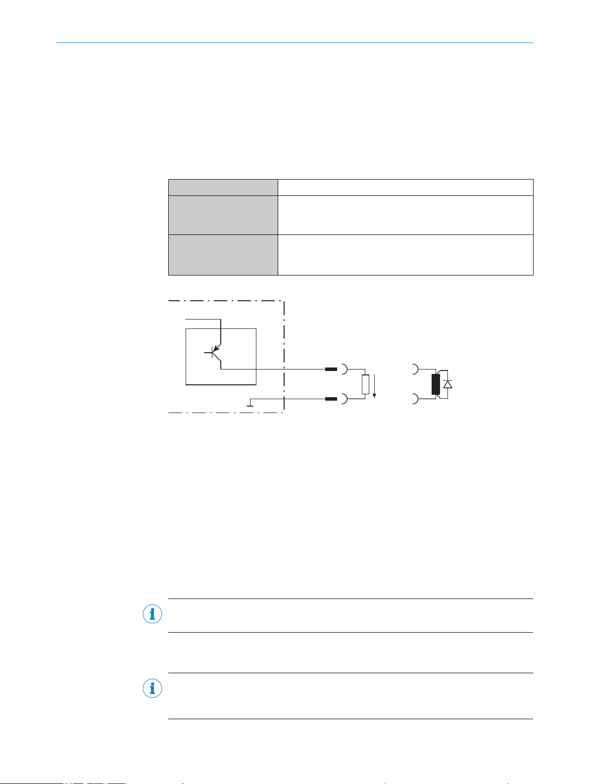
6.6.5 Wiring digital switching outputs
V
out
3
4
Switching output 1
!
"
Signal 2
GND
Physical switching outputs on the device
The physical switching outputs can be allocated independently of each other with vari‐
ous functions for event status indication. If the allocated event occurs in the read proc‐
ess, then the corresponding switching output is live after the end of the clock reading
pulse for the selected pulse duration.
Depending on the device, there are different numbers of switching outputs available on
the connections, see "Pin allocation of the connections", page 36.
ELECTRICAL INSTALLATION 6
Switching behavior PNP switching to supply voltage V
S
Properties Short-circuit protected
Temperature protected
Not electrically isolated from V
S
Electrical values The electrical values are identical for all switching outputs.
0 V ≤ V
(VS −1.5 V) ≤ V
out
≤ V
S
out
≤ VS at I
≤ 100 mA
out
Figure 42: Wiring of a switching output
Switching output (“Result 1” or “Result 2”)
1
Output signal
2
Output voltage V
3
With an inductive load: Sweep-out circuit – attach a freewheeling diode directly to the
4
out
load.
For pin assignment, see respective device
!..."
8014396/ZMG8/2017-07-04 | SICK O PE R AT I NG IN S TR U CT I ON S | CLV69x
Subject to change without notice
Extension: additional logical switching outputs in the device in the case of physical
“external” switching outputs on the optional connection module
Thanks to the optional CMC600 parameter memory module, the two additional switch‐
ing outputs “External output 1” and “External output 2” on the terminals in the connec‐
tion module are additionally available.
NOTE
These two external switching outputs are not suitable for time-critical applications.
If the wiring of the outputs is carried out via a connection module, then the relevant
operating instructions for the module must be followed.
NOTE
Capacitive loads on the switching outputs have an effect on the switch-on and switchoff behavior. The maximum capacity of 100 nF is a limit value.
49
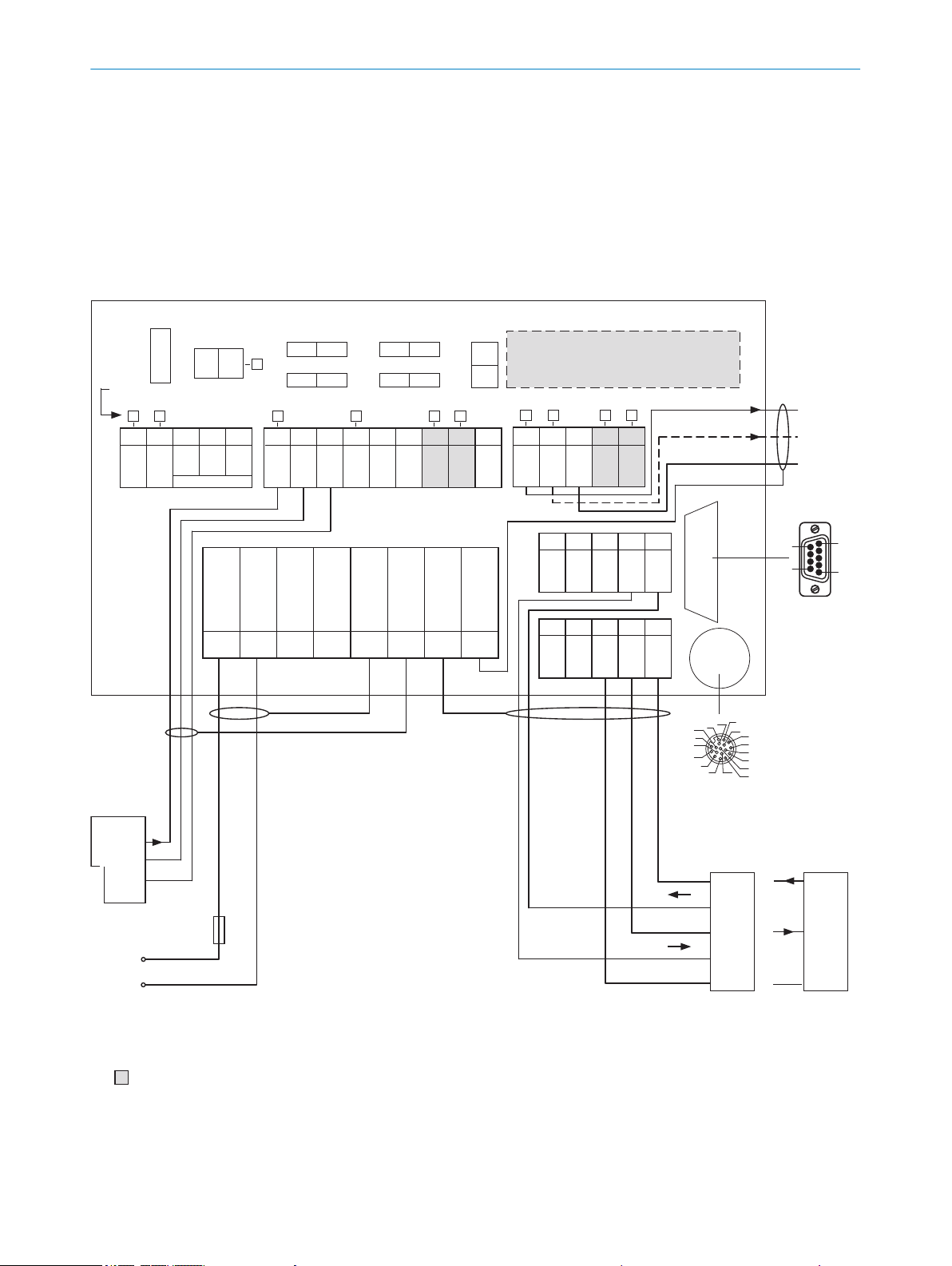
CDB650-204 connection module
Parameter memory module CMC600
(optional)
Term CAN
Term 485RS
SGND - GND
422 485
ONOFF
NO
YES
ONOFF
ONOFF
S2 S3
S7S6
S4
CMC
ONOFF
POWER
S1
30 31 32 33 34
CAN_H
CAN_L
T+
R+
GND
40 41 42 43 44
CAN_H
CAN_L
T‒/TxD
R‒/RxD
GND
AUX interface
5
1
9
6
U
IN
U
IN
GND
GND
Shield
Shield
Shield
Shield
1 2 3 4 5 6 7 8
LEDs
U
V
External
sensor for
read cycle
(e.g. photoelectric
sensor)
U
V
Out
GND
Result 1
PLC
GND
Result 2
to the PC
to the
CLV69x-xxx0
(without heating)
Pin
2: RxD
3: TxD
5: GND
Host
TD‒
TD+
RD+
RD‒
TxD
Host
RxD
GND
GND
RS-232
RS-422
UV = DC 18V ... 30V for CLV69x-xxx0 (without heating) at terminal UIN =
UIN* after switch S1, protected with internal fuse F
2A T
F
17
16
10
11
12
15
14
6
5
4
13
7
8
9
1
2
3
SENSOR
50 51 52 53 54
RES/
OUT 3
RES/
OUT 4
Ext. Illum.
TRL+GND
20 21 22 23 24
GND
RES/
OUT 1
RES/
OUT 2
EXT.
OUT 1
EXT.
OUT 2
10 11 12 13 14 15 16 17 18
U
IN
*
U
IN
*
SGND
SGND
SGND
EXT.
IN 1
SENS/
IN 1
SENS/
IN 2
EXT.
IN 2
RS-232
= For the additional use of the external switching inputs and outputs, the optional CMC600 parameter memory module is required.
Max.
2A
F
ext
ELECTRICAL INSTALLATION
6
1. Connecting the switching outputs according to the application
2. For the thorough check of the switching functions, use a high resistance digital
voltmeter and wire the switching outputs with a load.
This avoids the display of incorrect voltage values/output states.
6.7 Connection modules
6.7.1 Using connection module CDB650-204
Figure 43: Wiring overview (1 switching input used) for CLV69x-xxx0 (without heating)
50
O PE R AT I NG IN S TR U CT I ON S | CLV69x 8014396/ZMG8/2017-07-04 | SICK
Subject to change without notice
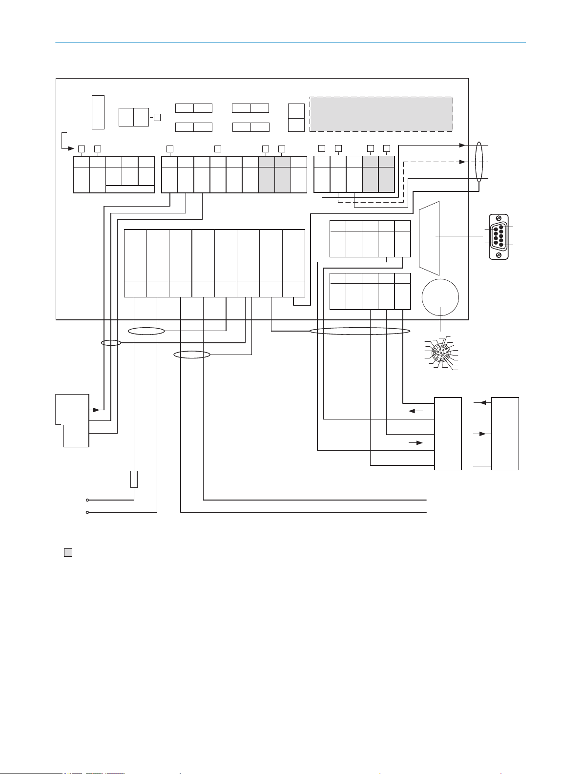
CDB650-204 connection module
Parameter memory module CMC600
(optional)
Term CAN
Term 485RS
SGND - GND
422 485
ONOFF
NO
YES
ONOFF
ONOFF
S2 S3
S7S6
S4
CMC
ONOFF
POWER
S1
30 31 32 33 34
CAN_H
CAN_L
T+
R+
GND
40 41 42 43 44
CAN_H
CAN_L
T‒/TxD
R‒/RxD
GND
AUX interface
5
1
9
6
U
IN
U
IN
GND
GND
Shield
Shield
Shield
Shield
1 2 3 4 5 6 7 8
LEDs
External
sensor for
read cycle
(e.g. photoelectric
sensor)
U
V
Out
GND
Result 1
PLC
GND
Result 2
to the PC
Pin
2: RxD
3: TxD
5: GND
Host
TD‒
TD+
RD+
RD‒
TxD
Host
RxD
GND
GND
RS-232
RS-422
UV = DC 21.6V ... 28.8V for CLV69x-xxx1 (with heating), protected by external fuse provided by user
2A T
F
17
16
10
11
12
15
14
6
5
4
13
7
8
9
1
2
3
SENSOR
50 51 52 53 54
RES/
OUT 3
RES/
OUT 4
Ext. Illum.
TRL+GND
20 21 22 23 24
GND
RES/
OUT 1
RES/
OUT 2
EXT.
OUT 1
EXT.
OUT 2
10 11 12 13 14 15 16 17 18
U
IN
*
U
IN
*
SGND
SGND
SGND
EXT.
IN 1
SENS/
IN 1
SENS/
IN 2
EXT.
IN 2
RS-232
= For the additional use of the external switching inputs and outputs, the optional CMC600 parameter memory module is required.
to the
CLV69x-xxx1
(with heating):
HOST/AUX/I/O
Voltage supply
to the CLV69x-xxx1
(with heating)
U
V
Max.
4A
F
ext
ELECTRICAL INSTALLATION
6
Figure 44: Wiring overview (1 switching input used) for CLV69x-xxx1 (with heating)
8014396/ZMG8/2017-07-04 | SICK O PE R AT I NG IN S TR U CT I ON S | CLV69x
Subject to change without notice
51
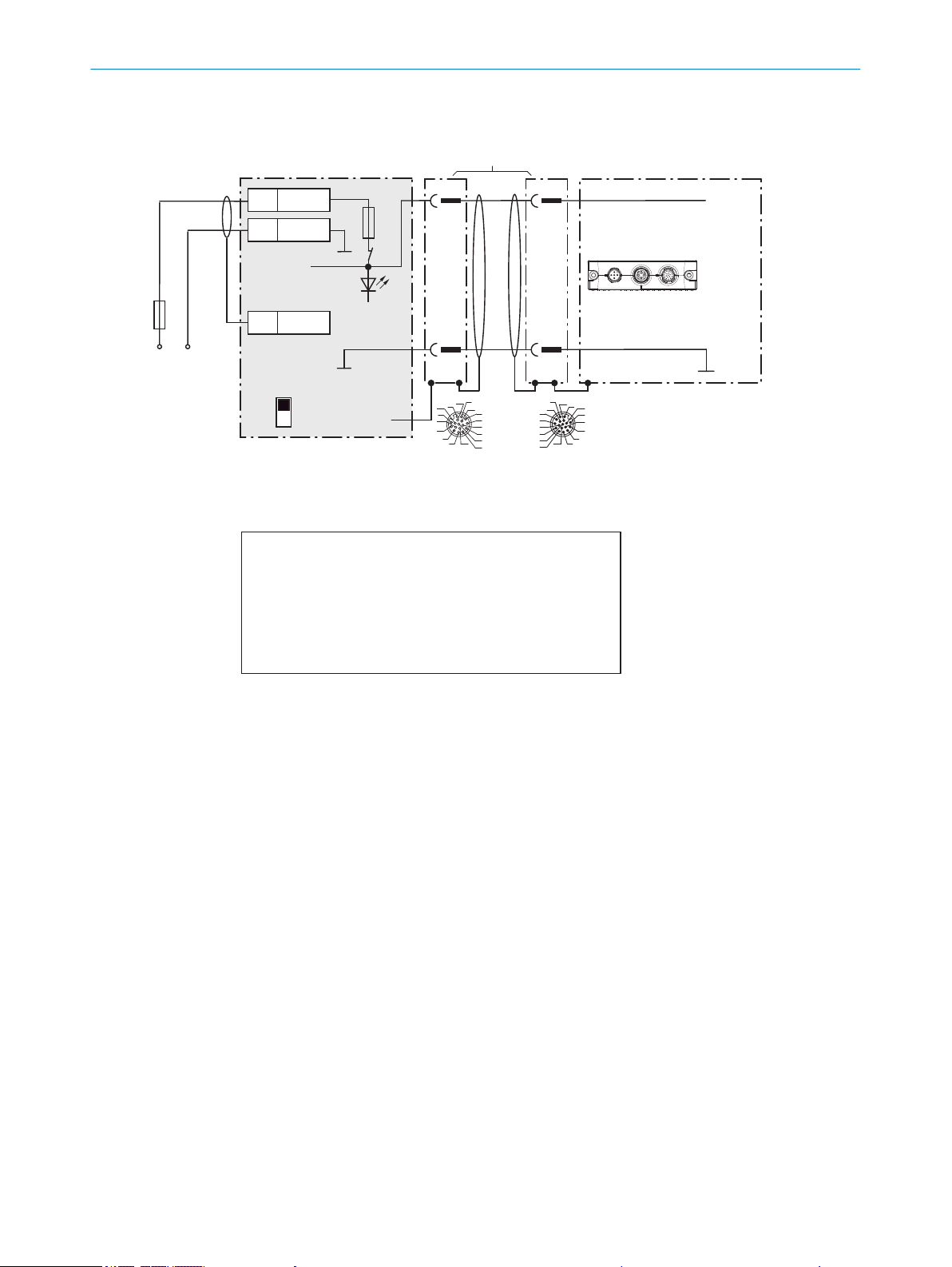
Wire supply voltage for CLV69x-xxx0 in the CDB650-204 connection module
CLV69x-xxx0 (without heating)
CDB650-204
UV
UV
2
1
2
1
5
Shield
1 U
IN
2 GND
UIN*
GND
S1
F
Shield
M12, 17-pin, A-coded
Connection
“HOST/AUX/I/O”
GND
.
.
.
.
.
.
.
.
.
ON
OFF
S1: POWER
DC 18V ... 30V
UIN*
POWER
UV = DC 18V ... 30V at terminal UIN =
UIN* after switch S1, protected with internal fuse F
17
16
10
11
12
15
14
6
5
4
13
7
8
9
1
2
3
17
16
10
11
12
15
14
6
5
4
13
7
8
9
1
2
3
1) connection cable 1:1:
no. 6052286 (2m)
no. 6051194 (3m)
no. 6051195 (5m)
Switch S1:
ON:
Supply voltage UIN connected via fuse as UIN* to CDB650-204
and CLV69x.
Voltage UIN* can also be tapped at terminal 11 and 14.
OFF:
CDB650-204 and CLV69x separated from supply voltage.
Recommended setting for all connection work.
Cloning plug
no. 2062452
Max.
2A
F
ext
Connection cable
1)
ELECTRICAL INSTALLATION
6
Figure 45: Wire supply voltage for CLV69x-xxx0 (without heating)
52
O PE R AT I NG IN S TR U CT I ON S | CLV69x 8014396/ZMG8/2017-07-04 | SICK
Subject to change without notice
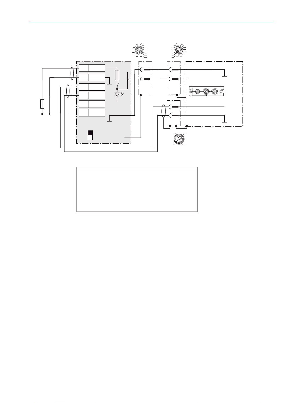
Wire supply voltage for CLV69x-xxx1 in the CDB650-204 connection module
CLV69x-xxx1 (with heating)
CDB650-204
UV
UV
2
1
2
2)
3
6
Shield
5
Shield
1 U
IN
2 GND
2 U
IN
2 GND
S1
F
M12 male connector, 5-pin,
A-coded
Cable1), e.g. no. 6053224 (5m)
GND
GND
ON
OFF
S1: POWER
DC 21.6V
... 28.8V
Max.
4A
UIN*
POWER
1) Adapter cable:
No. 6053224 (5m)
No. 6053225 (10m)
Cloning plug
No. 2062452 (B)
Connection
“CAN 1”
4
2
3
5
1
Red
Gray
Blue
17
16
10
11
12
15
14
6
5
4
13
7
8
9
1
2
3
GND
Shield
1
2
17
16
10
11
12
15
14
6
5
4
13
7
8
9
1
2
3
M12,
17-pin,
A-coded
F
Switch S1:
ON:
Supply voltage UIN connected via fuse as UIN* to CDB650-204
and CLV69x.
Voltage UIN* can also be tapped at terminal 11 and 14.
OFF:
CDB650-204 and CLV69x separated from supply voltage.
Recommended setting for all connection work.
2) Pin 2 in the
CLV69x-xxx1
(with heating)
not connected
.
.
.
.
.
.
ELECTRICAL INSTALLATION
6
Figure 46: Wire supply voltage for CLV69x-xxx1 (with heating)
8014396/ZMG8/2017-07-04 | SICK O PE R AT I NG IN S TR U CT I ON S | CLV69x
Subject to change without notice
53
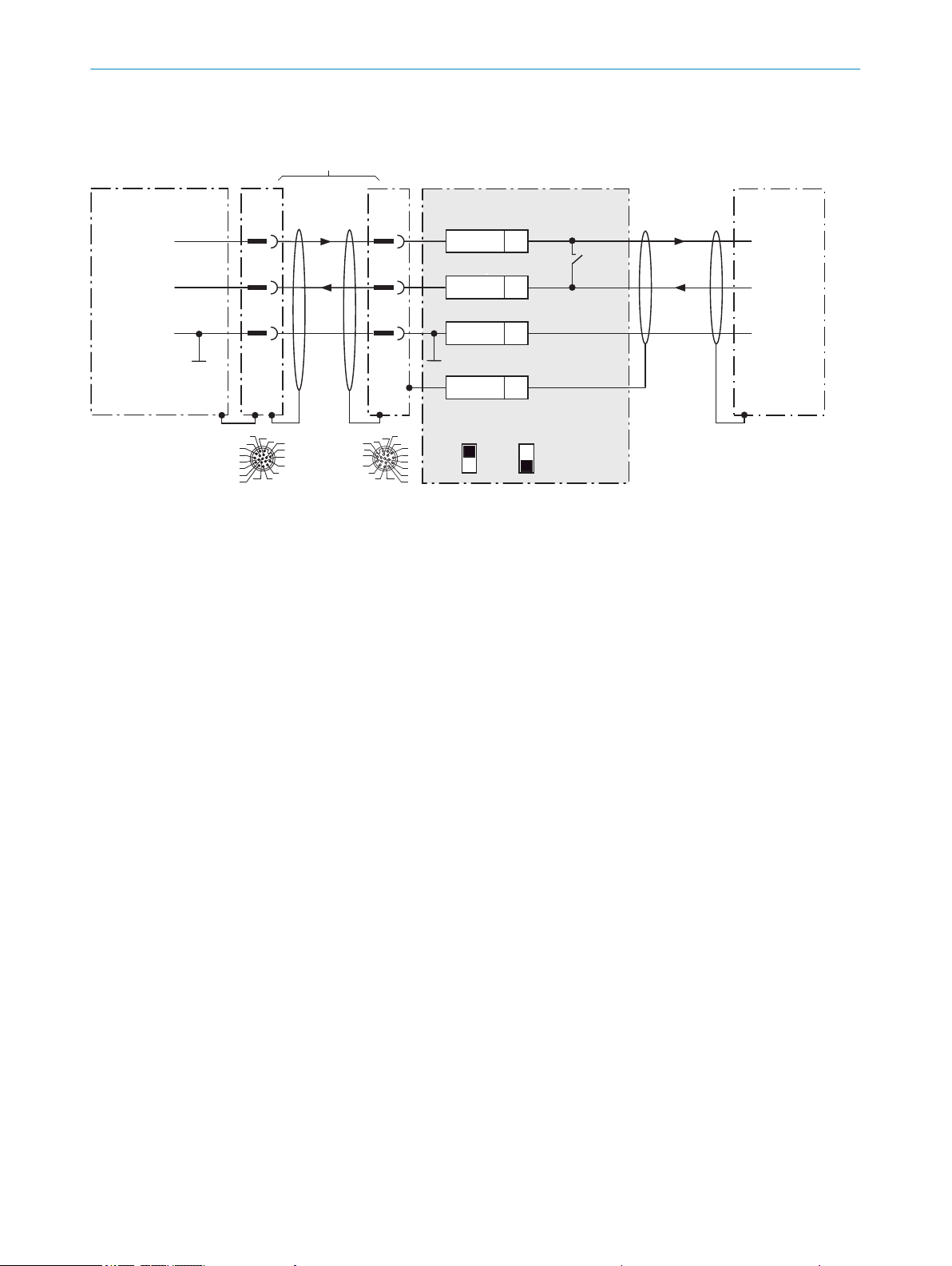
Wire RS-232 data interface of the CLV69x in the CDB650-204 connection module
CLV69x CDB650-204
Host
1
.
.
.
TxD
RxD
RxD
TxD
GND
GND
GND
12
1
6
12
6
43
T‒/TxD
44
R‒/RxD
42
GND
6
Shield
RS-232 RS-232
422
485
S6: RS
ON
OFF
S7: Term 485
S6
422485
M12,
17-pin,
A-coded
17
16
10
11
12
15
14
6
5
4
13
7
8
9
1
2
3
17
16
10
11
12
15
14
6
5
4
13
7
8
9
1
2
3
For CLV69x-xxx0 (without heating):
no. 6052286 (2m)
no. 6051194 (3m)
no. 6051195 (5m)
For CLV69x-xxx1 (with heating):
no. 6053230 (2m)
no. 6053231 (3m)
no. 6053232 (5m)
1) Dependent on type
Connection cable 1:1
1)
ELECTRICAL INSTALLATION
6
Figure 47: Wire serial host interface RS-232
54
O PE R AT I NG IN S TR U CT I ON S | CLV69x 8014396/ZMG8/2017-07-04 | SICK
Subject to change without notice
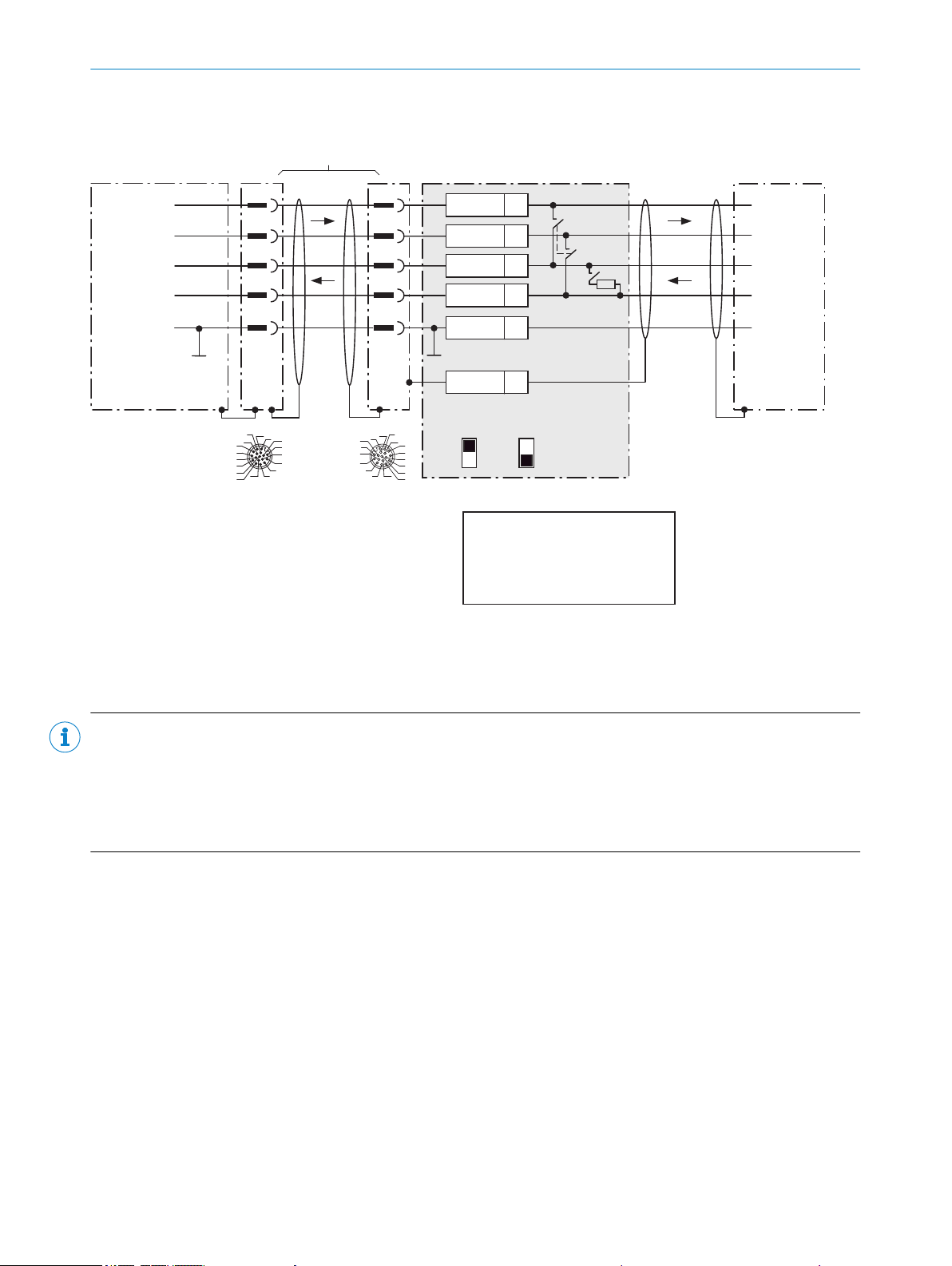
Connection cable 1:1
1)
Wire RS-422 data interface of the CLV69x in the CDB650-204 connection module
CLV69x CDB650-204
Host
1
.
.
.
TD+
TD‒
RD+
RD‒
RD+
RD‒
TD+
TD‒
GND
GND
GND
11
12
1
5 5
6
11
12
6
33
T+
43
T‒/TxD
34
R+
44
R‒/RxD
42
GND
6
Shield
RS-422 RS-422
422
485
S6: RS
ON
OFF
S7: Term 485
S6
422
S7
OFF
120 Ω
485
S7: Term 485
Set to ON, if termination of the
RS-422 receiver in the CLV69x is
needed to improve the interference
distance on the cable.
17
16
10
11
12
15
14
6
5
4
13
7
8
9
1
2
3
17
16
10
11
12
15
14
6
5
4
13
7
8
9
1
2
3
M12,
17-pin,
A-coded
For CLV69x-xxx0 (without heating):
no. 6052286 (2m)
no. 6051194 (3m)
no. 6051195 (5m)
For CLV69x-xxx1 (with heating):
no. 6053230 (2m)
no. 6053231 (3m)
no. 6053232 (5m)
1) Dependent on type
ELECTRICAL INSTALLATION 6
Figure 48: Wire serial host interface RS-422
NOTE
Use of the RS-422 data interface:
The relevant interface drivers for the device comply with the standard for RS-422 and RS-485.
•
Activation of the interface in the device with the SOPAS ET configuration software (point-to-point).
•
The connection shown above is configured for operation of the host with permanently activated drivers (often
•
described as “RS-422 operation”), i.e. not RS-485 bus operation.
8014396/ZMG8/2017-07-04 | SICK O PE R AT I NG IN S TR U CT I ON S | CLV69x
Subject to change without notice
55
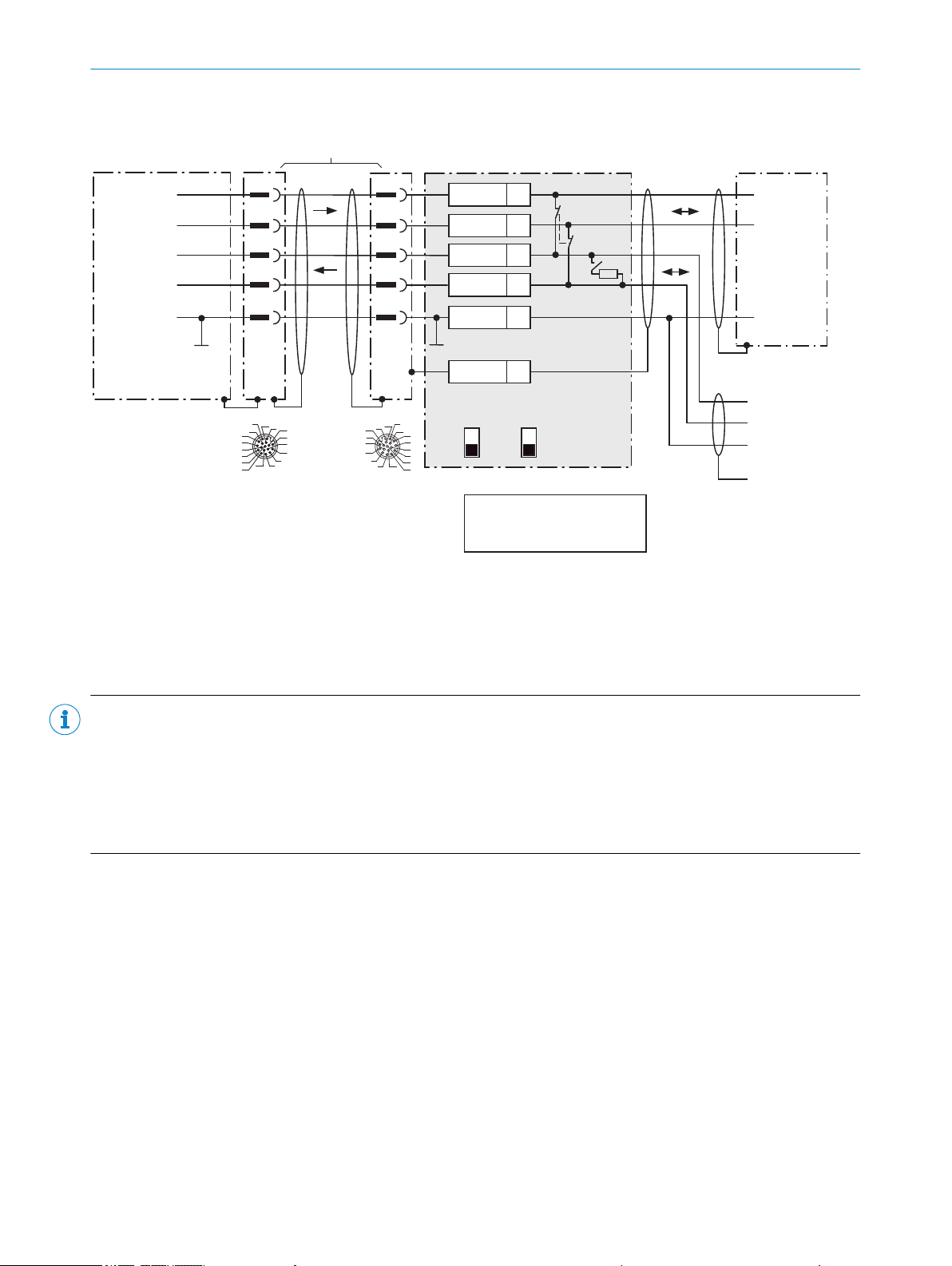
Wire RS-485 data interface of the CLV69x in the CDB650-204 connection module
CLV69x CDB650-204
Host
1
.
.
.
TD+
TD‒
RD+
RD‒
RD+/TD+
RD‒/TD‒
RD+/TD+
To the network:
RD‒/TD‒
GND
GND
GND
Shield
GND
11
12
1
5 5
6
11
12
6
33
T+
43
T‒/TxD
34
R+
44
R‒/RxD
42
GND
6
Shield
RS-485
RS-485
485
422
S6: RS
ON
OFF
S7: Term 485
S6
422
S7
OFF
120Ω
485
S7: Term 485
Set to ON if CLV69x is at the
end of the RS-485 bus cable.
17
16
10
11
12
15
14
6
5
4
13
7
8
9
1
2
3
17
16
10
11
12
15
14
6
5
4
13
7
8
9
1
2
3
M12,
17-pin,
A-coded
For CLV69x-xxx0 (without heating):
no. 6052286 (2m)
no. 6051194 (3m)
no. 6051195 (5m)
For CLV69x-xxx1 (with heating):
no. 6053230 (2m)
no. 6053231 (3m)
no. 6053232 (5m)
1) Dependent on type
Connection cable 1:1
1)
6 ELECTRICAL INSTALLATION
Figure 49: Wire serial host interface RS-485
NOTE
Use of the RS-485 data interface:
The relevant interface drivers for the device comply with the standard for RS-422 and RS-485.
•
This operating mode is only permitted if all connected devices use a corresponding RS-485 protocol.
•
Activation of the interface in the device with the SOPAS ET configuration software (point-to-point).
•
This wiring is not permitted in the standard data output/protocol for the device. In case of doubt, contact
•
SICK Service.
56
O PE R AT I NG IN S TR U CT I ON S | CLV69x 8014396/ZMG8/2017-07-04 | SICK
Subject to change without notice
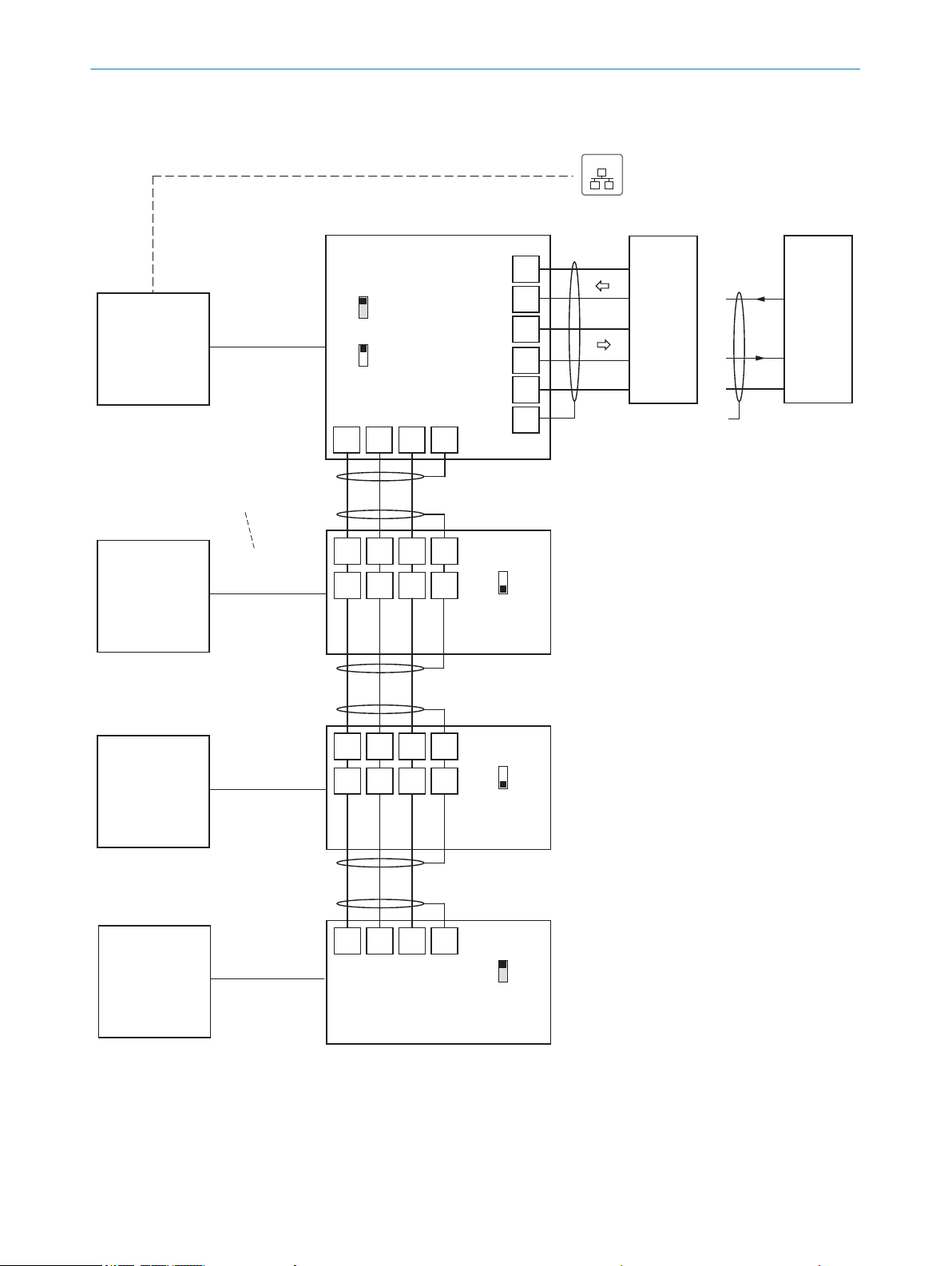
HostHost
Shield
30 31 32 6
30 31 32 6
30 31 32 6
33
34
43
44
6
30 31 32 6
40 41 42 7
40 41 42 7
CDB650204
CDB650204
CDB650204
CLV69x
CLV69x
CLV69x
(Slave)
(Slave)
(Slave)
GN = 01
CLV69x
(Master)
GN = 63
GN = 02
GN = 03
(max. 32 participants)
Branch line
Switch
ON
OFF
S2 (TermCAN):
Switch
ON
OFF
S2 (TermCAN):
Switch
ON
OFF
S2 (TermCAN):
CAN_H
CAN_L
Shield
GND
CAN_H
CAN_L
Shield
GND
CAN_H
CAN_L
Shield
GND
CAN_H
CAN_L
Shield
GND
GND
GND
GND
RxD
TxD
TD‒
RD‒
RD+
TD+
RS-232RS-422
T‒/TxD
R‒/RxD
T+
R+
CDB650-204
42
Connection
cable 1:1
1)
Connection
cable 1:1
1)
Connection
cable 1:1
1)
Connection
cable 1:1
1)
CAN
CAN
CAN
including CAN
including CAN
including CAN
including CAN
Connection and looping through
of the supply voltage and connection
of the read cycle sensor to e.g.
master neglected here!
Switch
ON
OFF
S2 (TermCAN):
Serial host interface
Ethernet (Host Port)
422
485
S6 (RS):
Wire CLV69x in the CDB650-204 connection module for SICK CAN SENSOR network
EthernetEthernet
For CLV69x-xxx0 (without heating):
no. 6052286 (2m)
no. 6051194 (3m)
no. 6051195 (5m)
For CLV69x-xxx1 (with heating):
no. 6053230 (2m)
no. 6053231 (3m)
no. 6053232 (5m)
1) Dependent on type
ELECTRICAL INSTALLATION
6
Figure 50: Wiring the CAN interface
8014396/ZMG8/2017-07-04 | SICK O PE R AT I NG IN S TR U CT I ON S | CLV69x
Subject to change without notice
57

Wire switching inputs “Sensor 1 ... 2” of the CLV69x in the CDB650-204 connection module
CLV69xCDB650-204
PNP sensor
UV
UV
UV
GND
SensGND
3.32K
6.64K
Sensor Z
U
e
Y
99
a) Sensor supplied via CDB650-204
2
2)
1
Y
2
1
12
SGND
6
Shield
11
UIN*
X Name
Out
UIN*
GND
S3
e.g. photoelectric
sensor
ON
OFF
S3: SGND-GND
Specifications of the switching inputs “Sensor 1 and 2”
Logic
Properties
Electrical values
Shield
GND
.
.
.
Ue = max. 32V
17
16
10
11
12
15
14
6
5
4
13
7
8
9
1
2
3
17
16
10
11
12
15
14
6
5
4
13
7
8
9
1
2
3
b) Sensor connected volt-free and supplied externally
CDB650-204
PNP sensor
UV
GND
12
SGND
6
Shield
11 UIN*
X
Out
UIN*
GND
S3
e.g. photoelectric
sensor
ON
OFF
S3: SGND-GND
U
V ext
Shield
Name
d) Diagram: switch connected volt-free and
supplied externally
Connection of the switch as under b)
c) Switch supplied via CDB650-204
UIN*
CDB650-204
12 SGND
6 Shield
11
UIN*
X
GND
S3
ON
OFF
S3: SGND-GND
Shield
Name
SensGND
GND
M12,
17-pin,
A-coded
Switch S3: SGND-GND
ON: GND of the switching inputs connected
with GND of the CDB650-204/CLV69x.
OFF: Sensors on switching inputs of the
CDB650-204/CLV69x connected volt-free.
Reference potential valid for all switching inputs
“SENS/IN 1 ... 2” and optionally “EXT. IN1 and 2”
CDB650-204 CLV69x
Terminal X
10
13
Name
SENS/IN 1
SENS/IN 2
Pin Y
10
15
Pin Y
10
15
Sensor Z
Sensor 1
Sensor 2
Functional allocation for switching inputs
via SOPAS-ET configuration software.
For CLV69x-xxx0 (without heating):
no. 6052286 (2m)
no. 6051194 (3m)
no. 6051195 (5m)
For CLV69x-xxx1 (with heating):
no. 6053230 (2m)
no. 6053231 (3m)
no. 6053232 (5m)
1) Dependent on type
Connection cable 1:1
1)
2) Pin 2 in the CLV69x-xxx1
(with heating) not
connected
Current to input starts the assigned
function, e.g. start read cycle.
(Default CLV69x: logic active high,
debounce 10mm)
– Opto-decoupled, reverse-polarity
protected
– Can be wired with PNP output of a sensor
– SensGND is the shared, insulated
reference potential for all switching inputs
Low: Ue ≤ 2V; Ie ≤ 0.3mA
High: 6V ≤ Ue ≤ 32V;
0.7mA ≤ Ie ≤ 5mA
ELECTRICAL INSTALLATION
6
Figure 51: Wiring switching inputs “Sensor 1 and 2”
58
O PE R AT I NG IN S TR U CT I ON S | CLV69x 8014396/ZMG8/2017-07-04 | SICK
Subject to change without notice
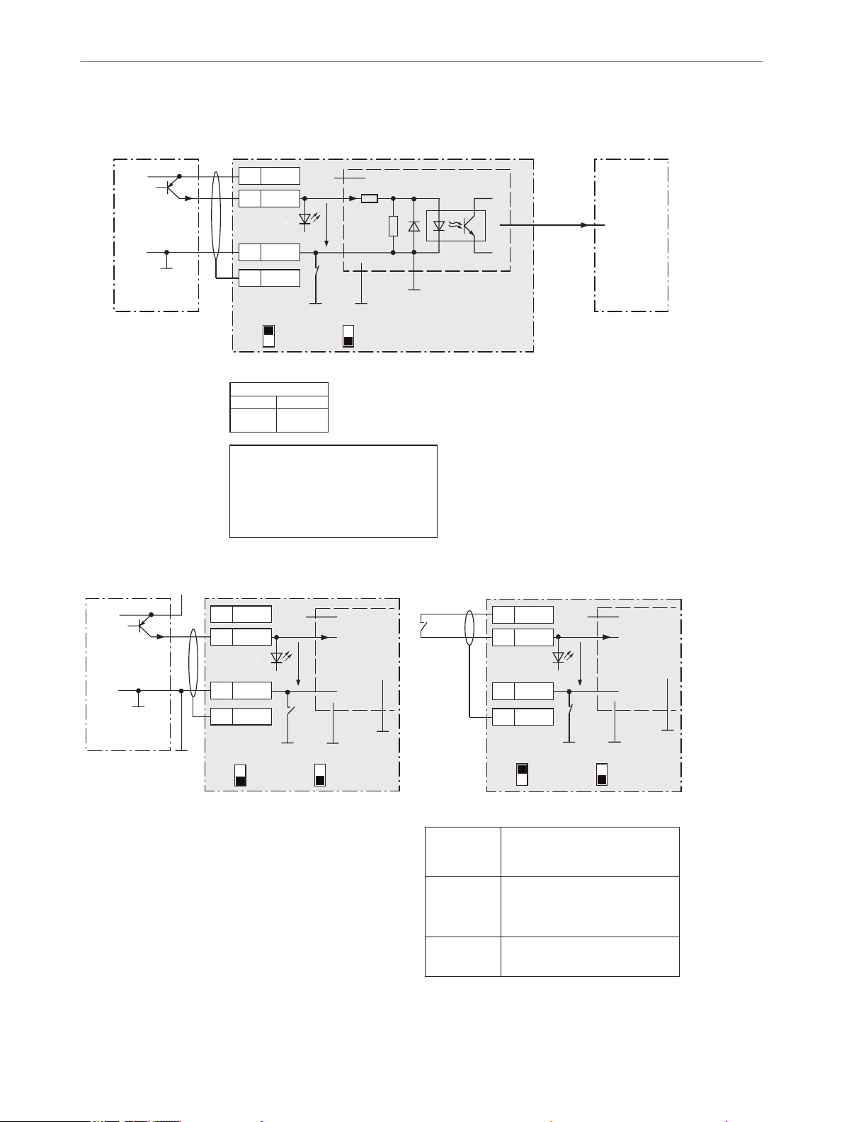
Wire switching inputs “External input 1 and 2” of the CLV69x in the CDB650-204 connection module
CLV69xCDB650-204
PNP sensor
UV
GND
3.32K
6.64K
Ue = max. 32V
18
SGND
8
Shield
11
UIN*
X Name
Out
GND
S3
e.g. photoelectric
sensor
CMC600
UIN*
a) Sensor supplied via CDB650-204
b) Sensor connected volt-free and supplied externally
d) Switch connected volt-free and supplied externally
Connection of the switch as under b)
Serial Aux
(RS-232)
ON
OFF
S3: SGND-GND
No
YES
S4: CMC
Ue
The output states of the physical inputs
“EXT. IN 1 and 2“ are transmitted by the
CMC600 automatically in a softwarecontrolled manner via the connecting cable
to the serial Aux interface of the CLV69x.
The CLV69x implements the status on its
logical inputs “External input 1 and 2”.
“External
input 1,
input 2”
SensGND
c) Switch supplied via CDB650-204
CDB650-204
18 SGND
8 Shield
11
UIN*
X
Name
GND
S3
UIN*
CMC600
ON
OFF
S3: SGND-GND
No
YES
S4: CMC
U
e
SensGND
CDB650-204
PNP sensor
UV
GND
18
SGND
8
Shield
11 UIN*
X
Out
GND
S3
e.g. photoelectric
sensor
U
V ext
Name
CMC600
UIN*
No
YES
S4: CMC
ON
OFF
S3: SGND-GND
U
e
SensGND
Switch S3: SGND-GND
ON: GND of the switching inputs connected
with GND of the CDB650-204/CMC600.
OFF: Sensors on switching inputs of the
CDB650-204/CMC600 connected volt-free.
Reference potential valid for all switching inputs
“SENS/IN 1 ... 2” and optionally “EXT. IN1 and 2”
CDB650-204
16
17
Terminal X Name
EXT. IN 1
EXT. IN 2
Specifications of the switching inputs “Ext. input 1 and 2”
Functional allocation for switching inputs
via SOPAS-ET configuration software.
Logic
Properties
Electrical values
Current to input starts the assigned
function, e.g. start read cycle.
(Default CLV69x: logic active high,
debounce 10mm)
– Opto-decoupled, reverse-polarity
protected
– Can be wired with PNP output of a sensor
– SensGND is the shared, insulated
reference potential for all switching inputs
Low: Ue ≤ 2V; Ie ≤ 0.3mA
High: 6V ≤ Ue ≤ 32V;
0.7mA ≤ Ie ≤ 5mA
ELECTRICAL INSTALLATION
6
Figure 52: Wiring switching inputs “External input 1 and 2”
8014396/ZMG8/2017-07-04 | SICK O PE R AT I NG IN S TR U CT I ON S | CLV69x
Subject to change without notice
59

Wire switching outputs “Result 1 ... 4” of the CLV69x in the CDB650-204 connection module
CLV69x
CDB650-204
Load (e.g. PLC)
Y
1
.
.
.
Z
Name
22
GND
5Shield
UIN*U
V
GND
Ua
Result X
GND
Y
1
2
2)
2
Discharge wiring:
apply free running
diode directly to
the load!
In the case of inductive load:
17
16
10
11
12
15
14
6
5
4
13
7
8
9
1
2
3
17
16
10
11
12
15
14
6
5
4
13
7
8
9
1
2
3
M12,
17-pin,
A-coded
CDB650-204CLV69x
Terminal ZNamePin YPin YResult X
20
21
50
51
RES/OUT 1
RES/OUT 2
RES/OUT 3
RES/OUT 4
13
14
16
17
13
14
16
17
Result 1
Result 2
Result 3
Result 4
For CLV69x-xxx0 (without heating):
no. 6052286 (2m)
no. 6051194 (3m)
no. 6051195 (5m)
For CLV69x-xxx1 (with heating):
no. 6053230 (2m)
no. 6053231 (3m)
no. 6053232 (5m)
2) Pin 2 in the CLV69x-xxx1
(with heating) not connected
1) Dependent on type
Specifications of the switching outputs “Result 1 ... 4”
Functional allocation for switching outputs via SOPAS-ET
configuration software.
Connection cable 1:1
1)
Logic
Properties
Electrical
values
PNP switching to supply voltage UV.
CLV69x default:
Result 1: Device Ready (static), logic: active high
Result 2: Good Read, 100mm, logic: active high
Result 3: no function assigned
Result 4: no function assigned
– Short-circuit protected + temperature protected
– Not electrically isolated from UV (+ 24V*)
0V ≤ Ua ≤ U
V
Guaranteed:
(UV − 1.6V) ≤ Ua ≤ UV in the case of Ia ≤ 100mA
ELECTRICAL INSTALLATION
6
Figure 53: Wiring switching outputs “Result 1 to 4”
60
O PE R AT I NG IN S TR U CT I ON S | CLV69x 8014396/ZMG8/2017-07-04 | SICK
Subject to change without notice

Wire switching outputs “External output 1 and 2” of the CLV69x on the CDB650-204 connection module
Load (e.g. PLC)
GND
Discharge wiring:
apply free running
diode directly to
the load!
In the case of
inductive load:
Ua
Specifications of the switching outputs “External output 1 and 2”
CLV69x
Serial Aux
(RS-232)
CDB650-204
CMC600
UIN*
The CLV69x releases the output states of its logical
outputs “External output 1 and 2” via its serial Aux
interface.
Via the connecting cable, the CMC600 automatically
accepts the statuses in a software-controlled manner
and transfers them to its physical outputs “EXT. OUT 1
and 2“ in the CDB650-204.
“External
output 1,
output 2”
Z
Name
22
GND
6Shield
CDB650-204CLV69x
Terminal ZNameOutput
23
24
EXT. OUT 1
EXT. OUT 2
External output 1
External output 2
Functional allocation for switching outputs via
SOPAS-ET configuration software.
Logic
Properties
Electrical
values
PNP switching to supply voltage UIN*
(default: no function,
logic: not inverted [active high])
–Short-circuit protected + temperature protected
– Not electrically isolated from UIN*
0V ≤ Ua ≤ UIN*
Guaranteed:
(UIN* −1.5V) ≤ Ua ≤ UIN* in the case of Ia ≤ 100mA
ELECTRICAL INSTALLATION
6
Figure 54: Wiring switching outputs “External output 1 and 2”
8014396/ZMG8/2017-07-04 | SICK O PE R AT I NG IN S TR U CT I ON S | CLV69x
Subject to change without notice
61

ON
OFF
ON
OFF
ON
OFF
Connection module CDM420-0006
Parameter memory module CMC600
(optional)
2 A T
S8
No CMC ->
SCANNER
AUX interface
6110 5
1115
LEDs
31 32 33 34 35 36 37 38 39 40
T‒/TxD
R‒/RxD
+24V*
Sensor 1
Aux Out 1
GND
GND
SGND
CAN_H
CAN_L
11 12 13 14 15 16 17 18 19 20
Result 1
Result 2
Aux In 2
Aux In 1
SGND
GND
GND
SGND
internal
internal
21 22 23 24 25 26 27 28 29 30
T+
R+
+24V*
Sensor 2
Aux Out 2
GND
GND
SGND
CAN_H
CAN_L
1 2 3 4
+24V
+24V
GND
GND
5 6 7 8
Shield
Shield
Shield
Shield
POWER
Sensor 1
Sensor 2
Result 1
Result 2
S1
POWER
ON
OFF
S2 S3 S4 S6
ON
OFF
ON
OFF
RS485
Term422
TermCAN
SGND - GND
1 5
6 9
to PC
Pin
2: RxD
3: TxD
5: GND
Result 1
PLC
GND
Result 2
External sensor
for reading cycle
(e.g. photoelectric
sensor)
U
V
Out
GND
Host
TD‒
TD+
RD+
RD‒
TxD
Host
RxD
GND
GND
RS-232RS-422
RS-485
F
to CLV69x-xxx0
(without heating)
= For additional use of external switching inputs and outputs, the optional CMC600 parameter memory module is required.
UV = DC 18V ... 30V for CLV69x-xxx0 (without heating) at terminal +24V =
+24V* after switch S1, protected by internal fuse F
U
V
Max.
2A
F
ext
ELECTRICAL INSTALLATION
6
6.7.2 Using connection module CDM420-0006
Figure 55: Wiring overview (1 switching input used) for CLV69x-xxx0 (without heating)
62
O PE R AT I NG IN S TR U CT I ON S | CLV69x 8014396/ZMG8/2017-07-04 | SICK
Subject to change without notice

ON
OFF
ON
OFF
ON
OFF
Connection module CDM420-0006
Parameter memory module CMC600
(optional)
2 A T
S8
No CMC ->
SCANNER
AUX interface
6110 5
1115
LEDs
31 32 33 34 35 36 37 38 39 40
T‒/TxD
R‒/RxD
+24V*
Sensor 1
Aux Out 1
GND
GND
SGND
CAN_H
CAN_L
11 12 13 14 15 16 17 18 19 20
Result 1
Result 2
Aux In 2
Aux In 1
SGND
GND
GND
SGND
internal
internal
21 22 23 24 25 26 27 28 29 30
T+
R+
+24V*
Sensor 2
Aux Out 2
GND
GND
SGND
CAN_H
CAN_L
1 2 3 4
+24V
+24V
GND
GND
5 6 7 8
Shield
Shield
Shield
Shield
POWER
Sensor 1
Sensor 2
Result 1
Result 2
S1
POWER
ON
OFF
S2 S3 S4 S6
ON
OFF
ON
OFF
RS485
Term422
TermCAN
SGND - GND
1 5
6 9
to PC
Pin
2: RxD
3: TxD
5: GND
Result 1
PLC
GND
Result 2
External sensor
for reading cycle
(e.g. photoelectric sensor)
U
V
Out
GND
Host
TD‒
TD+
RD+
RD‒
TxD
Host
RxD
GND
GND
RS-232RS-422
RS-485
F
to
CLV69x-xxx1
(with heating)
= For additional use of external switching inputs and outputs, the optional CMC600 parameter memory module is required.
UV = DC 21.6V ... 28.8V for CLV69x-xxx1 (with heating), protected by external fuse provided by user
Max.
4 A
F
ext
Voltage supply to
CLV69x-xxx1
(with heating)
U
V
ELECTRICAL INSTALLATION
6
Figure 56: Wiring overview (1 switching input used) for CLV69x-xxx1 (with heating)
8014396/ZMG8/2017-07-04 | SICK O PE R AT I NG IN S TR U CT I ON S | CLV69x
Subject to change without notice
63
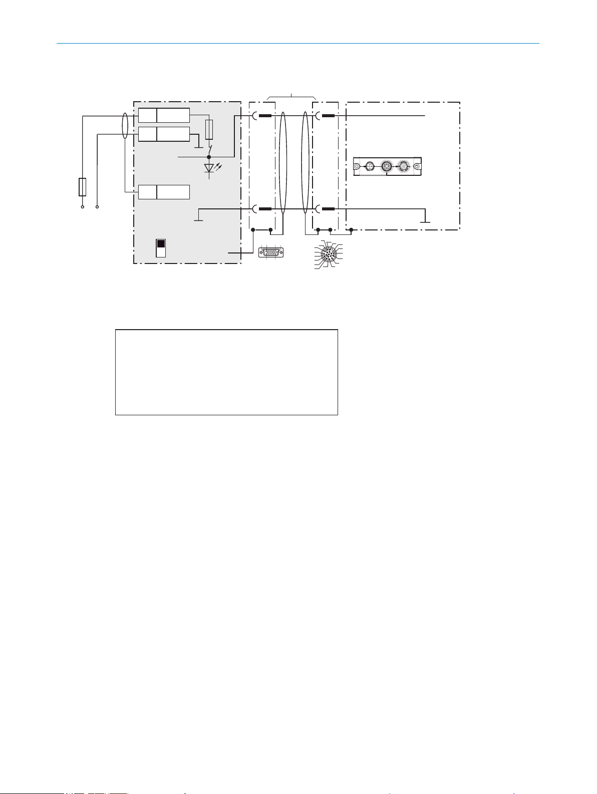
Wire supply voltage for CLV69x-xxx0 in the CDM420-0006 connection module
CLV69x-xxx0 (without heating)
CDM420-0006
U
V
U
V
2
1
1
5
5
Shield
1 +24V
2 GND
+24V*
GND
S1
F
Shield
D-Sub-HD
female
connector, 15-pin
M12 male connector,
17-pin, A-coded
GND
.
.
.
.
.
.
.
.
.
ON
OFF
S1 : POWER
DC 18V ... 30V
+24V*
POWER
UV = DC 18V ... 30V at terminal +24V =
UV at terminal +24V* after switch S1, protected by internal fuse F
17
16
10
11
12
15
14
6
5
4
13
7
8
9
1
2
3
6110 5
1115
Switch S1:
ON:
supply voltage UV (+24V) switched via fuse as UV (+24V*)
to CDM420-0006 and CLV69x.
UV (+24V*) can also be engaged at terminal 29 and 39.
OFF:
CDM420-0006 and CLV69x separated from supply voltage.
Recommended position for all connection types.
For CLV69x-xxx0 (without heating):
No. 2049764 (0.9m)
no. 2055419 (2m)
no. 2055420 (3m)
No. 2055859 (5m)
1) Adapter cable
Cloning plug
No. 2062452
“HOST/AUX/I/O”
connection
Max.
2A
F
Adapter cable
1)
ELECTRICAL INSTALLATION
6
Figure 57: Wire supply voltage for CLV69x-xxx0 (without heating)
64
O PE R AT I NG IN S TR U CT I ON S | CLV69x 8014396/ZMG8/2017-07-04 | SICK
Subject to change without notice
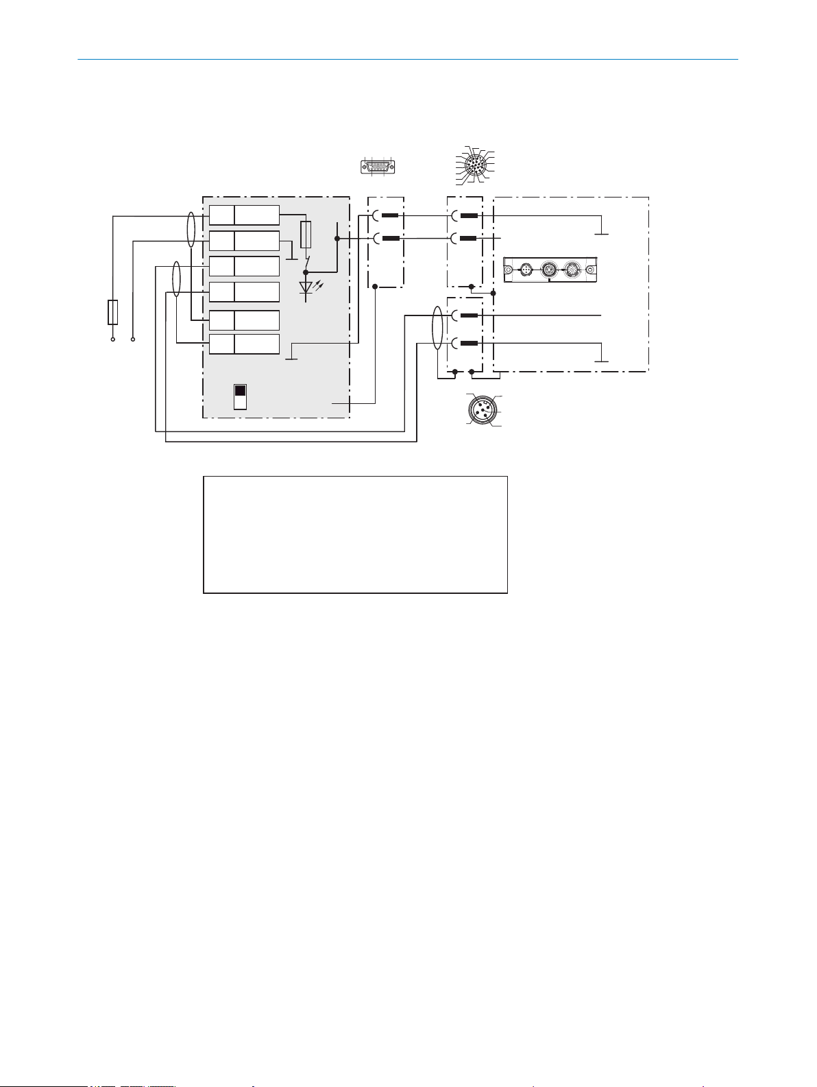
Wire supply voltage for CLV69x-xxx1 in the CDM420-0006 connection module
CLV69x-xxx1 (with heating)
CDM420-0006
1
2
3
5
5
Shield
6
Shield
1 +24V
2 GND
3 +24V
4 GND
GND
S1
F
UV
UV
Shield
D-Sub-HD
female connector,
15-pin
M12 male connector,
17-pin, A-coded
GND
GND
.
.
.
ON
OFF
S1 : POWER
+24V*
POWER
17
16
10
11
12
15
14
6
5
4
13
7
8
9
1
2
3
6110 5
1115
Cloning plug
No. 2062452
Max.
4A
F
M12 male connector 5-pin,
A-coded
1) Adapter cable:
No. 6053224 (5m)
No. 6053225 (10m)
Connection
“CAN 1”
4
2
3
5
1
Switch S1:
ON:
supply voltage UV (+24V) switched via fuse as UV (+24V*)
to CDM420-0006 and CLV69x.
UV (+24V*) can also be engaged at terminal 29 and 39.
OFF:
CDM420-0006 and CLV69x separated from supply voltage.
Recommended position for all connection types.
Adapter cable
1)
DC 21.6V
... 28.8V
red
Gray
Blue
2) Pin 2 in CLV69x-xxx1
(with heating) not
connected
2
2)
1
ELECTRICAL INSTALLATION
6
Figure 58: Wire supply voltage for CLV69x-xxx1 (with heating)
8014396/ZMG8/2017-07-04 | SICK O PE R AT I NG IN S TR U CT I ON S | CLV69x
Subject to change without notice
65
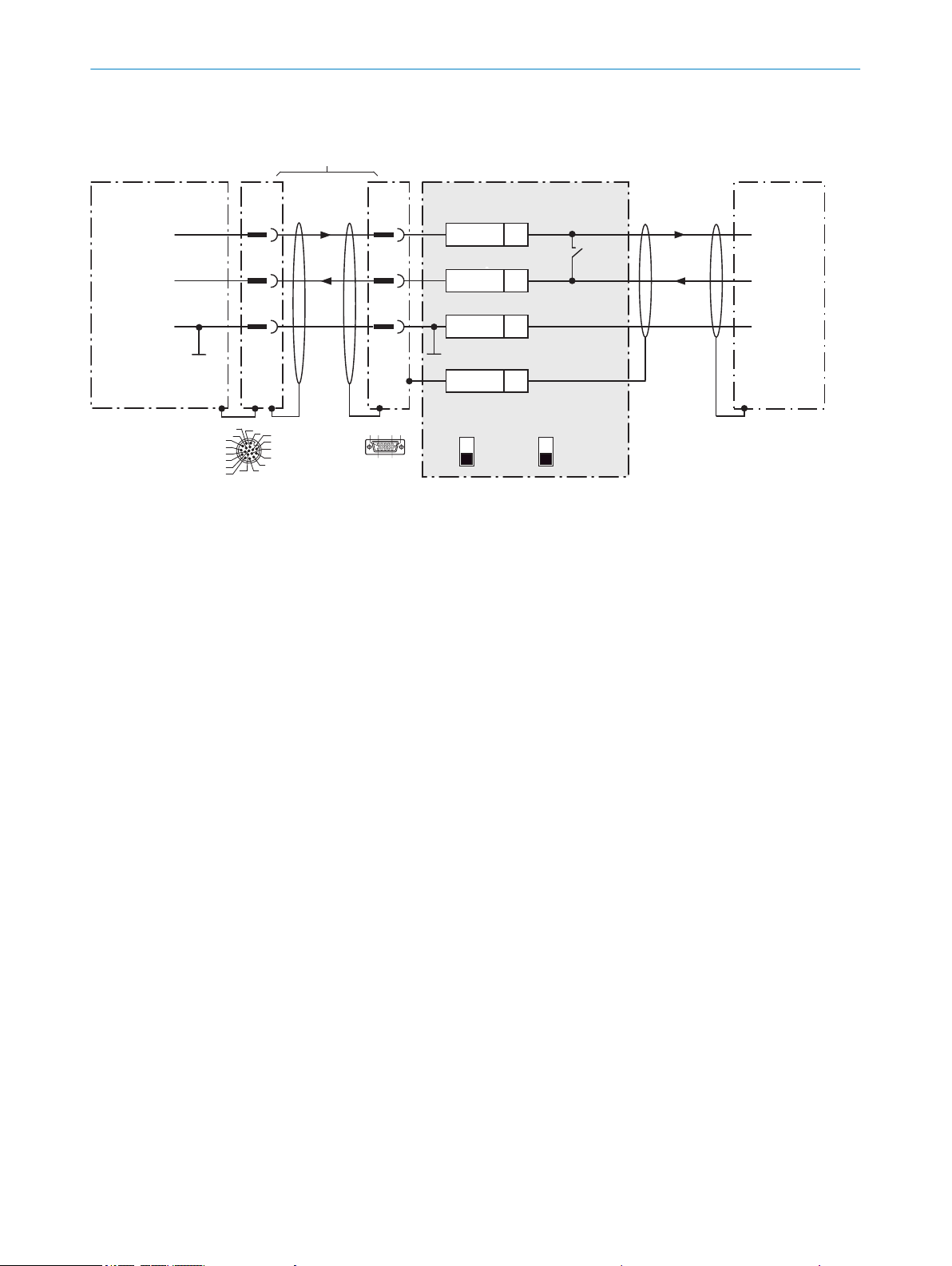
Wire RS-232 data interface of the CLV69x in the CDM420-0006 connection module
CLV69x CDM420-0006
Host
D-Sub-HD female
connector,
15-pin
M12 male connector
17-pin,
A-coded
5
.
.
.
TxD
RxD
RxD
TxD
GND
GND
GND
12
1
9
7
6
34
T‒/TxD
35
R‒/RxD
36
GND
6
Shield
RS-232 RS-232
ON
OFF
S2 : RS 485
ON
OFF
S3: Term 422
S2
OFF485
17
16
10
11
12
15
14
6
5
4
13
7
8
9
1
2
3
For CLV69x-xxx0 (without heating):
No. 2049764 (0.9m)
No. 2055419 (2m)
No. 2055420 (3m)
No. 2055859 (5m)
For CLV69x-xxx1 (with heating):
No. 2061480 (2m)
No. 2061605 (3m)
No. 2061481 (5m)
1) Dependent on type
6110 5
1115
Adapter cable
1)
ELECTRICAL INSTALLATION
6
Figure 59: Wire serial host interface RS-232
66
O PE R AT I NG IN S TR U CT I ON S | CLV69x 8014396/ZMG8/2017-07-04 | SICK
Subject to change without notice
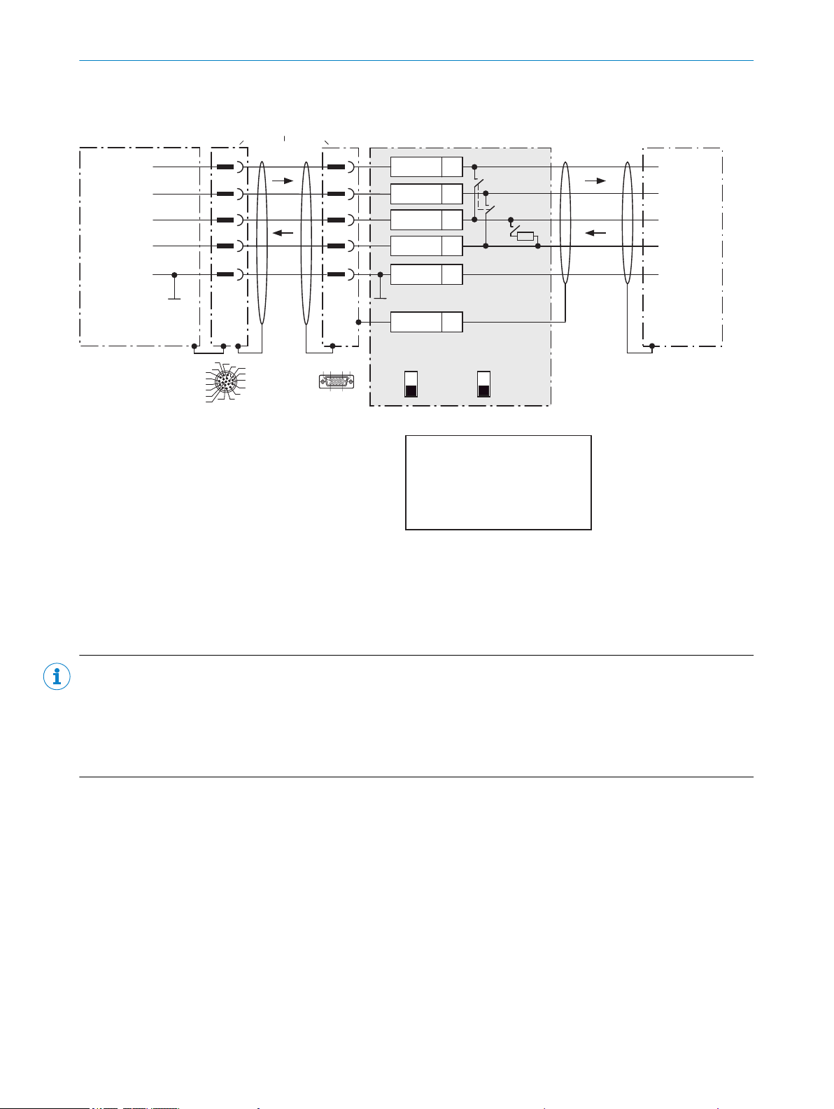
Wire RS-422 data interface of the CLV69x in the CDM420-0006 connection module
CLV69x CDM420-0006
Host
D-Sub-HD female
connector
15-pin
M12 male
connector
17-pin, A-coded
5
.
.
.
TD+
TD‒
RD+
RD‒
RD+
RD‒
TD+
TD‒
GND
GND
GND
11
12
1
5 8
9
6
7
6
24
T+
34
T‒/TxD
25
R+
35
R‒/RxD
36
GND
6
Shield
RS-422 RS-422
ON
OFF
S2 : RS 485
ON
OFF
S3: Term 422
S2
OFF
S3
OFF
120Ω
17
16
10
11
12
15
14
6
5
4
13
7
8
9
1
2
3
6110 5
1115
For CLV69x-xxx0 (without heating):
No. 2049764 (0.9m)
No. 2055419 (2m)
No. 2055420 (3m)
No. 2055859 (5m)
For CLV69x-xxx1 (with heating):
No. 2061480 (2m)
No. 2061605 (3m)
No. 2061481 (5m)
1) Dependent on type
S3: Term 422
Set to ON if termination
of the RS-422 receiver in the CLV69x
is necessary to improve the
signal-to-interference ratio on the
cable.
Adapter cable
1)
ELECTRICAL INSTALLATION 6
Figure 60: Wire serial host interface RS-422
NOTE
Use of the RS-422 data interface:
The relevant interface drivers for the device comply with the standard for RS-422 and RS-485.
•
Activation of the interface in the device with the SOPAS ET configuration software (point-to-point).
•
The connection shown above is configured for operation of the host with permanently activated drivers (often
•
described as “RS-422 operation”), i.e. not RS-485 bus operation.
8014396/ZMG8/2017-07-04 | SICK O PE R AT I NG IN S TR U CT I ON S | CLV69x
Subject to change without notice
67
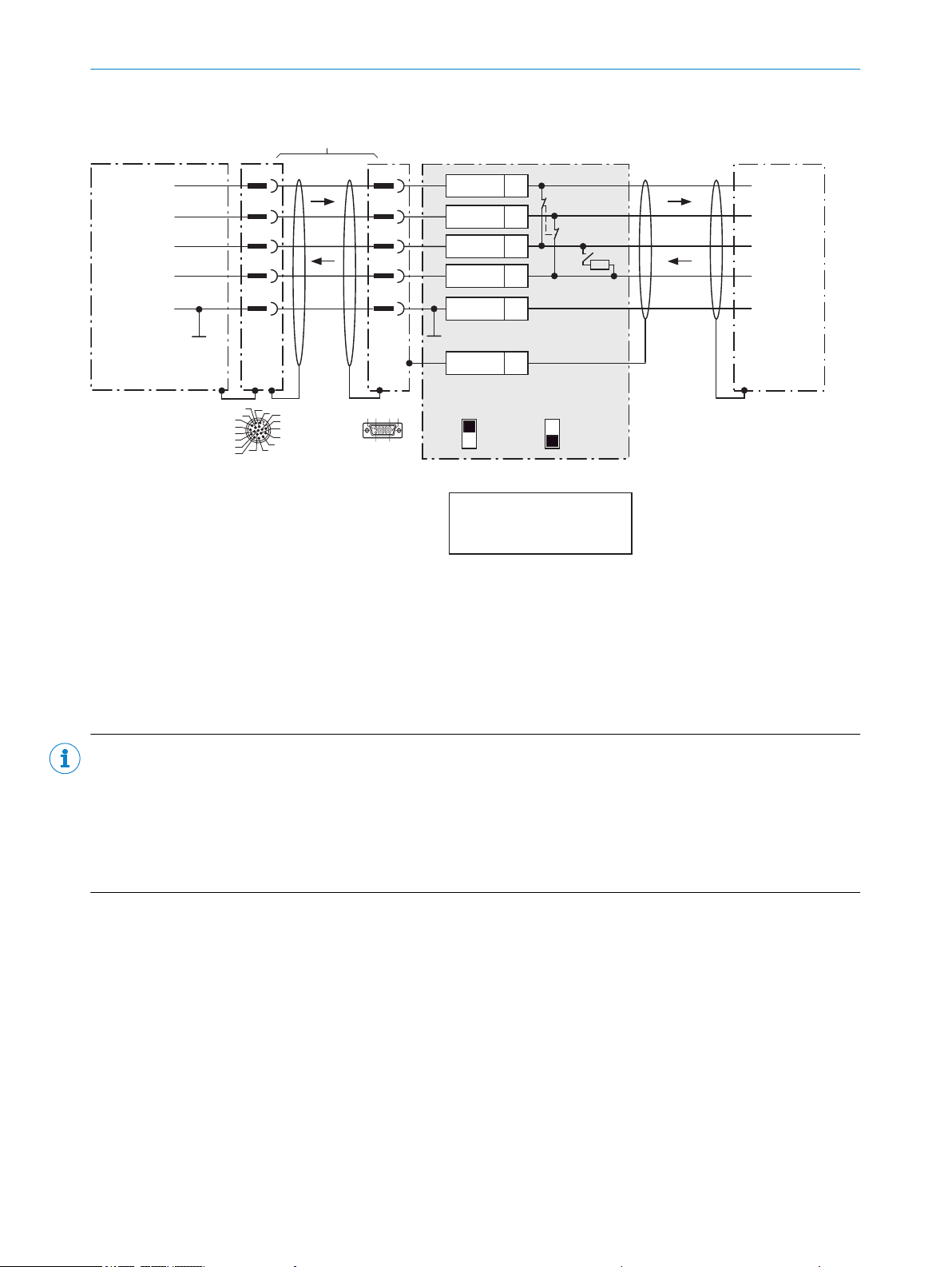
Wire RS-485 data interface of the CLV69x in the CDM420-0006 connection module
CLV69x CDM420-0006
Host
5
.
.
.
TD+
TD‒
RD+
RD‒
RD+
RD‒
TD+
TD‒
GND
GND
GND
11
12
1
5
8
9
6
7
6
24
T+
34
T‒/TxD
25
R+
35
R‒/RxD
36
GND
6
Shield
RS-485 RS-485
ON
OFF
S2 : RS 485
ON
OFF
S3: Term 422
S2
ON
S3
OFF
120 Ω
D-Sub-HD female
connector,
15-pin
M12 male
connector,
17-pin, A-coded
17
16
10
11
12
15
14
6
5
4
13
7
8
9
1
2
3
6110 5
1115
For CLV69x-xxx0 (without heating):
No. 2049764 (0.9m)
No. 2055419 (2m)
No. 2055420 (3m)
No. 2055859 (5m)
For CLV69x-xxx1 (with heating):
No. 2061480 (2m)
No. 2061605 (3m)
No. 2061481 (5m)
1) Dependent on type
S3: Term 422
Set to ON if the CLV69x is at the
end of the RS-485 bus cable.
Adapter cable
1)
6 ELECTRICAL INSTALLATION
Figure 61: Wire serial host interface RS-485
NOTE
Use of the RS-485 data interface:
The relevant interface drivers for the device comply with the standard for RS-422 and RS-485.
•
This operating mode is only permitted if all connected devices use a corresponding RS-485 protocol.
•
Activation of the interface in the device with the SOPAS ET configuration software (point-to-point).
•
This wiring is not permitted in the standard data output/protocol for the device. In case of doubt, contact
•
SICK Service.
68
O PE R AT I NG IN S TR U CT I ON S | CLV69x 8014396/ZMG8/2017-07-04 | SICK
Subject to change without notice
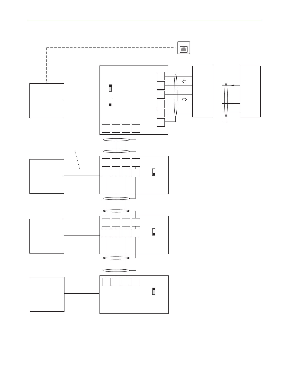
EthernetEthernet
HostHost
Shield
24
25
34
35
7
CDM420-0006
CDM420-0006
CDM420-0006
CLV69x
CLV69x
CLV69x
(Slave)
(Slave)
(Slave)
GN = 01
CLV69x
(Master)
GN = 63
GN = 02
GN = 03
(max. 32 participants)
Branch line
Switch
ON
OFF
S4 (TermCAN):
Switch
ON
OFF
S4 (TermCAN):
Switch
ON
OFF
S4 (TermCAN):
21 22 23 6
21 22 23 6
31 32 33 7
21 22 23 6
21 22 23 6
31 32 33 7
CAN_H
CAN_L
Shield
GND
CAN_H
CAN_L
Shield
GND
CAN_H
CAN_L
Shield
GND
CAN_H
CAN_L
Shield
GND
GND
GND
GND
RxD
TxD
TD‒
RD‒
RD+
TD+
RS-232RS-422
T‒/TxD
R‒/RxD
T+
R+
CDM420-0006
26
CAN
CAN
CAN
CAN 1,
among others
CAN 1,
among others
CAN 1,
among others
CAN 1,
among others
Connection and looping of the supply
voltage and connection of the read
cycle sensor, e.g. to host, is neglected
here.
Switch
ON
OFF
S4 (TermCAN):
Serial host interface
Ethernet (Host Port)
ON
OFF
S2 (RS485):
Wire CLV69x in the CDM420-0006 connection module for SICK CAN SENSOR network
CAN_H = CAN1_H CLV69x
CAN_L = CAN1_L CLV69x
S4 (TermCAN = TermCAN1)
For CLV69x-xxx0 (without heating):
No. 2049764 (0.9m)
No. 2055419 (2m)
No. 2055420 (3m)
No. 2055859 (5m)
For CLV69x-xxx1 (with heating):
No. 2061480 (2m)
No. 2061605 (3m)
No. 2061481 (5m)
1) Dependent on type
Adapter cable
1)
Adapter cable
1)
Adapter cable
1)
Adapter cable1)
ELECTRICAL INSTALLATION
6
Figure 62: Wiring the CAN interface
8014396/ZMG8/2017-07-04 | SICK O PE R AT I NG IN S TR U CT I ON S | CLV69x
Subject to change without notice
69
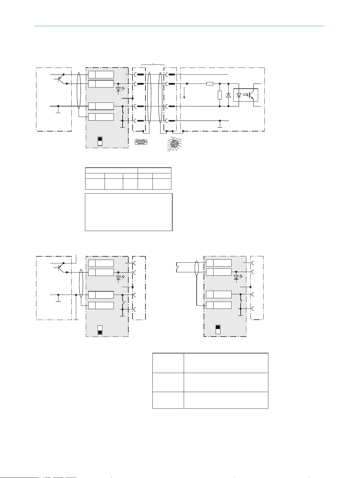
Wire “Sensor 1 and 2” switching inputs of the CLV69x in the CDM420-0006 connection module
CLV69xCDM420-0006
PNP sensor
UV
UV
UV
GND
GND
SensGND
3.32K
6.64K
Sensor Z
U
e
Y2
9
a) Sensor supplied by CDM420-0006
a) Switch supplied by CDM420-0006
2
2)
1
Y1
15
1
5
Out
+24V*
GND
S6
e.g. photoelectric sensor
ON
OFF
S6 : SGND-GND
Characteristic data of the switching inputs “Sensor 1 and 2”
Current at the input starts the assigned function,
e.g. start reading cycle.
(CLV69x default settings:
logic active high, debouncing 10mm)
– Opto-decoupled, reverse polarity protected
– Can be wired with PNP output of a sensor
– SensGND is the common insulated
reference potential for all switching inputs
Low: Ue ≤ 2 V; Ie ≤ 0.3mA
High: 6V ≤ Ue ≤ 32V;
0.7mA ≤ Ie ≤ 5mA
Switching
behavior
Properties
Electrical values
Switch S6 : SGND-GND
ON: connect GND of the sensor to the GND of
the CDM420-0006/CLV69x.
OFF: sensors connected volt-free to CDM420 0006/CLV69x.
Reference potential valid for all “Sensor 1 and 2”
switching inputs and optionally “AUX In 1 and 2”
Shield
D-Sub-HD female
connector, 15-pin
M12 male
connector,
17-pin, A-coded
GND
.
.
.
X
Name
37
SGND
6
Shield
39
+24V*
Ue = max. 32V
+24V*
CDM420-0006
GND
S6
ON
OFF
S6 : SGND-GND
Shield
38
Sensor 1
37
SGND
6
Shield
39
+24V*
b) Sensor connected volt-free and externally supplied
+24V*
CDM420-0006
PNP sensor
UV
GND
Out
GND
S6
e.g. photoelectric
sensor
ON
OFF
S6 : SGND-GND
U
V ext
Shield
38
Sensor 1
37
SGND
6
Shield
39
+24V*
17
16
10
11
12
15
14
6
5
4
13
7
8
9
1
2
3
6110 5
1115
d) Switch connected volt-free
and externally supplied
Connection of the switch as under b)
Functional assignment for switching inputs via
SOPAS-ET configuration software
For CLV69x-xxx0 (without heating):
No. 2049764 (0.9m)
No. 2055419 (2m)
No. 2055420 (3m)
No. 2055859 (5m)
For CLV69x-xxx1 (with heating):
No. 2061480 (2m)
No. 2061605 (3m)
No. 2061481 (5m)
1) Dependent on type
CDM420-0006
CLV69x
Terminal X
38
28
Name
Sensor 1
Sensor 2
Pin Y1
14
4
Pin Y2
10
15
Sensor Z
Sensor 1
Sensor 2
Adapter cable
1)
2) Pin 2 in CLV69x-xxx1
(with heating) not
connected
ELECTRICAL INSTALLATION
6
Figure 63: Wiring switching inputs “Sensor 1 and 2”
70
O PE R AT I NG IN S TR U CT I ON S | CLV69x 8014396/ZMG8/2017-07-04 | SICK
Subject to change without notice
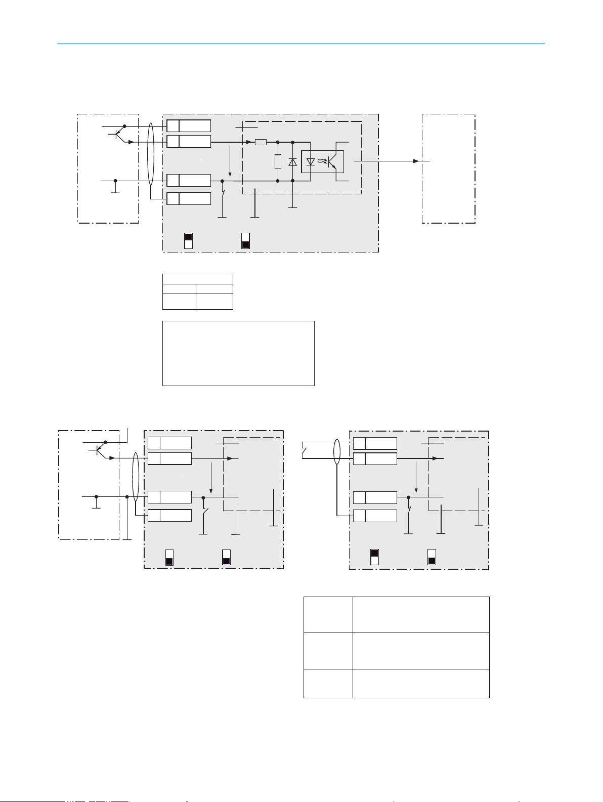
Ue = max. 30V
Wire switching inputs “Ext. input 1 and 2” of the CLV69x on the CDM420-0006 connection module
CLV69x
CDM420-0006
PNP sensor
UV
GND
3.32K
6.64K
U
e
Out
GND
S6
e.g. photoelectric sensor
CMC600
a) Sensor supplied by CDM420-0006
Serial Aux
(RS-232)
ON
OFF
S6 : SGND-GND
No
YES
S8 : CMC
17
SGND
8
Shield
39
+24V*
X
Name
+24V*
The CMC600 automatically transmits the
output states of its physical “Aux In 1 and
2” inputs to the serial Aux interface of the
CLV69x via the connecting cable using
software.
The CLV69x translates the statuses to its
logical “External input 1 and 2“ inputs.
“External
input 1,
input 2”
Characteristic data of switching inputs “Ext. input 1 and 2”
Current at the input starts the assigned
function, e.g. start reading cycle. (CLV69x
default settings: logic active high, debouncing 10mm)
– Opto-decoupled, reverse polarity protected
– Can be wired with PNP output of a sensor
– SensGND is the common insulated
reference potential for all switching inputs
Low: Ue ≤ 2V; Ie ≤ 0.3mA
High: 6V ≤ Ue ≤ 30V;
0.7mA ≤ Ie ≤ 5mA
Switching
behavior
Properties
Electrical
values
a) Switch supplied by CDM420-0006
CDM420-0006
U
e
GND
S6
CMC600
ON
OFF
S6 : SGND
No
YES
S8 : CMC
17
SGND
8
Shield
39
+24V*
18
Aux In 1
+24V*
SensGND
CDM420-0006
PNP sensor
UV
GND
Out
GND
S6
e.g. photoelectric
sensor
U
V ext
U
e
CMC600
b) Sensor connected volt-free and externally supplied
No
YES
S8 : CMC
ON
OFF
S6 : SGND
17
SGND
8
Shield
39
+24V*
18
Aux In 1
+24V*
SensGND
SensGND
d) Switch connected volt-free
and externally supplied
Connection of the switch as under b)
Functional assignment for switching inputs
via SOPAS-ET configuration software
CDM420-0006
Terminal X
18
19
Name
Aux In 1
Aux In 2
Switch S6 : SGND
ON: connect GND of the switching inputs with
the GND of the CDM420-0006/CMC600.
OFF: sensors connected volt-free to the switching
inputs of the CDM420-0006/CMC600.
Reference potential valid for all “Sensor 1 and 2”
switching inputs and optionally “AUX In 1 and 2”.
ELECTRICAL INSTALLATION
6
Figure 64: Wiring switching inputs “External input 1 and 2”
8014396/ZMG8/2017-07-04 | SICK O PE R AT I NG IN S TR U CT I ON S | CLV69x
Subject to change without notice
71
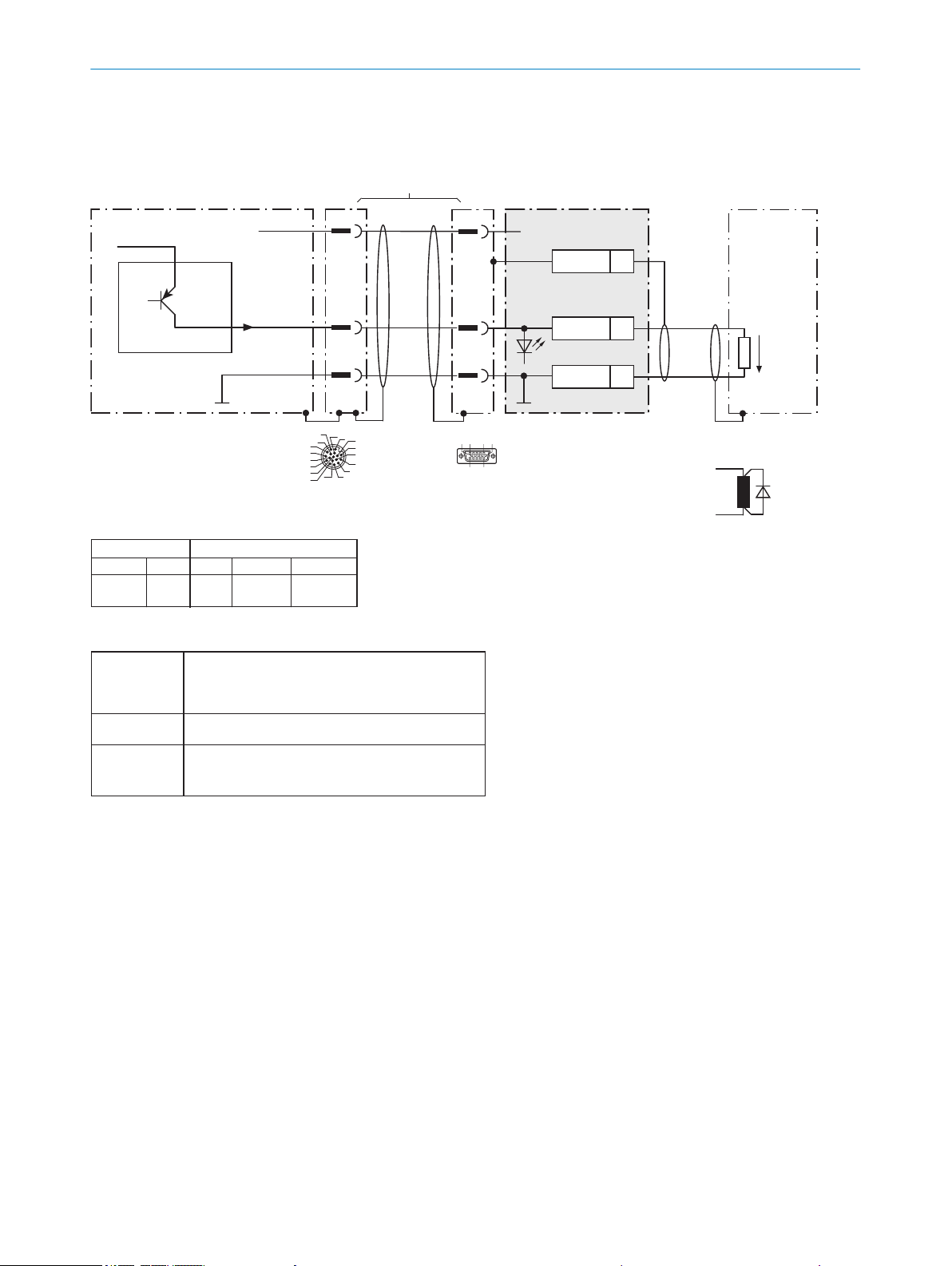
Wire “Result 1 and 2” switching outputs of the CLV69x in the CDM420-0006 connection module
CLV69x
CDM420-0006
Load (e.g. PLC)
Adapter cable
1)
Y2
5
.
.
.
Z
Name
13
GND
5
Shield
+24V* (UV)
U
V
GND
Sweep-out circuit:
Attach a freewheeling diode directly
to the load.
With inductive load:
Ua
Result X
GND
Y1
1
2
2)
1
D-Sub-HD
female connector, 15-pin
M12 male connector,
17-pin, A-coded
17
16
10
11
12
15
14
6
5
4
13
7
8
9
1
2
3
6110 5
1115
For CLV69x-xxx0 (without heating):
No. 2049764 (0.9m)
No. 2055419 (2m)
No. 2055420 (3m)
No. 2055859 (5m)
For CLV69x-xxx1 (with heating):
No. 2061480 (2m)
No. 2061605 (3m)
No. 2061481 (5m)
1) Dependent on type
2) Pin 2 in CLV69x-xxx1
(with heating) not connected
Characteristic data of “Result 1 and 2” switching outputs
PNP switching to supply voltage U
V
CLV69x default settings:
Result 1: device ready (static), logic: active high
Result 2: good read, 100mm, logic: active high
–Short-circuit protected + temperature protected
–Not electrically isolated from supply voltage (+24V*)
0V ≤ Ua ≤ U
V
Guaranteed:
(UV − 1.6V) ≤ Ua ≤ UV at Ia ≤ 100mA
Switching
behavior
Properties
Electrical
values
Functional assignment for switching outputs
via SOPAS-ET configuration software!
CDM420-0006CLV69x
Terminal Z
14
15
Name
Result 1
Result 2
Pin Y2
12
13
Pin Y1
13
14
Result X
Result 1
Result 2
ELECTRICAL INSTALLATION
6
Figure 65: Wiring switching outputs “Result 1 and 2”
72
O PE R AT I NG IN S TR U CT I ON S | CLV69x 8014396/ZMG8/2017-07-04 | SICK
Subject to change without notice
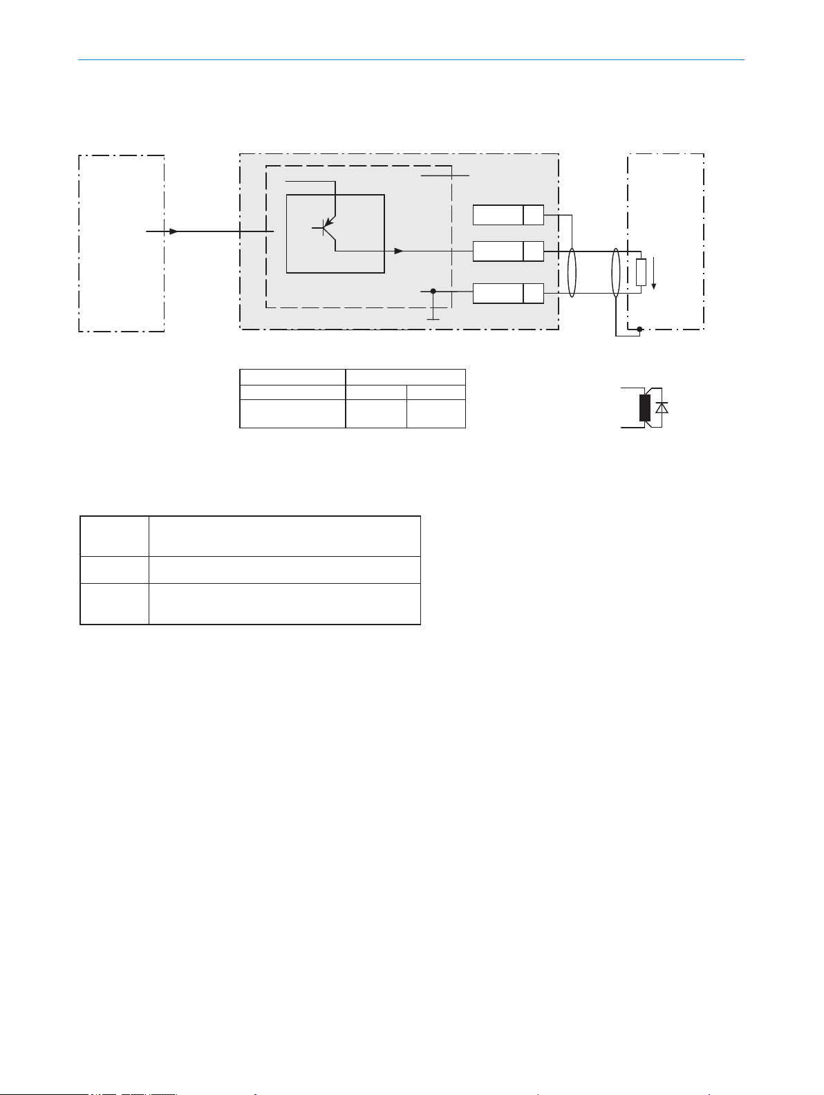
Wire switching outputs “Ext. output 1 and 2” of the CLV69x on the CDM420-0006 connection module
Load (e.g. PLC)
GND
Sweep-out circuit:
Attach a freewheeling
diode directly to the load.
With inductive load:
Ua
CLV69x
Serial Aux
(RS-232)
CDM420-0006
+24V* = UV after fuse
CMC600
+24V* (UV)
Z
Name
36
GND
6
Shield
“External
output 1,
output 2”
Characteristic data of “External output 1 and 2” switching outputs
PNP switching to supply voltage UV
(Default settings: no function,
logic: not inverted [active high])
–Short-circuit protected + temperature protected
–Not electrically isolated from supply voltage (+24V*)
0V ≤ Ua ≤ U
V
Guaranteed:
(UV −1.5V) ≤ Ua ≤ UV at Ia ≤ 100mA
Switching
behavior
Properties
Electrical
values
The CLV69x issues the output states of its “External
output 1 and 2” logical outputs via its serial AUX
interface.
Via the connecting cable, the CMC600 automatically
adopts the statuses and translates them to its
physical “AUX Out 1 and 2” outputs in the
CDM420-0006 using software.
CDM420-0006
CLV69x
Terminal Z
40
30
Name
Aux Out 1
Aux Out 2
Output
External output 1
External output 2
Functional assignment for switching outputs
via SOPAS-ET configuration software
ELECTRICAL INSTALLATION
6
Figure 66: Wiring switching outputs “External output 1 and 2”
8014396/ZMG8/2017-07-04 | SICK O PE R AT I NG IN S TR U CT I ON S | CLV69x
Subject to change without notice
73

ON
OFF
ON
OFF
Connection module CDM490-0001 (basic card)
2 A T
S8
No CMC ->
SCANNER
HOST/AUX
AUX interface
6110 5
1115
LED
31 32 33 34 35 36 37 38 39
T‒/TxD
R‒/RxD
GND
GND
GND
CAN_H
CAN_L
11 12 13 14 15 16 17 18 19
CAN2_H
CAN2_L
internal
internal
GND
GND
GND
CAN2_H
CAN2_L
1 2 3 4
+24V
+24V
GND
GND
5 6 7 8
Shield
Shield
Shield
Shield
POWER
S1
POWER
ON
OFF
S2 S3 S4
ON
OFF
ON
OFF
RS485
Term422
TermCAN
ON
OFF
S5
TermCAN2
To CLV69x-xxx0
(“HOST/AUX”)
1 5
6 9
To PC
Pin
2: RxD
3: TxD
5: GND
21 22 23 24 25 26 27 28 29
T+
R+
+24V*
GND
GND
GND
Pin14 n.u.
Pin11 n.u.
CAN_H
CAN_L
Host
TD‒
TD+
RD+
RD‒
TxD
Host
RxD
GND
GND
RS-232RS-422
RS-485
F
CAN_H = CAN1_H
CAN_L = CAN1_L
U
V
Max.
2A
F
ext
UV = DC 18V ... 30V for CLV69x-xxx0 (without heating) at terminal +24V =
+24V* after switch S1, protected by internal fuse F
ELECTRICAL INSTALLATION
6
6.7.3 Using connection module CDM490-0001
Figure 67: Wiring overview, part 1 (basic map below left), for CLV69x-xxx0 (without heating)
74
O PE R AT I NG IN S TR U CT I ON S | CLV69x 8014396/ZMG8/2017-07-04 | SICK
Subject to change without notice

ON
OFF
ON
OFF
Connection module CDM490-0001 (basic card)
2 A T
S8
No CMC ->
SCANNER
HOST/AUX
AUX interface
6110 5
1115
LED
31 32 33 34 35 36 37 38 39
T‒/TxD
R‒/RxD
GND
GND
GND
CAN_H
CAN_L
11 12 13 14 15 16 17 18 19
CAN2_H
CAN2_L
internal
internal
GND
GND
GND
CAN2_H
CAN2_L
1 2 3 4
+24V
+24V
GND
GND
5 6 7 8
Shield
Shield
Shield
Shield
POWER
S1
POWER
ON
OFF
S2 S3 S4
ON
OFF
ON
OFF
RS485
Term422
TermCAN
ON
OFF
S5
TermCAN2
To CLV69x-xxx1
("HOST/AUX")
1 5
6 9
To PC
Pin
2: RxD
3: TxD
5: GND
21 22 23 24 25 26 27 28 29
T+
R+
+24V*
Pin4 n.u.
Pin14 n.u.
Pin11 n.u.
GND
GND
GND
CAN_H
CAN_L
Host
TD‒
TD+
RD+
RD‒
TxD
Host
RxD
GND
GND
RS-232RS-422
RS-485
F
CAN_H = CAN1_H
CAN_L = CAN1_L
U
V
Max.
4 A
F
ext
UV = DC 21.6V ... 28.8V for CLV69x-xxx1 (with heating), protected by external fuse provided by user
Voltage supply to
CLV69x-xxx1
(with heating)
ELECTRICAL INSTALLATION
6
Figure 68: Wiring overview, part 1 (basic map below left), for CLV69x-xxx1 (with heating)
8014396/ZMG8/2017-07-04 | SICK O PE R AT I NG IN S TR U CT I ON S | CLV69x
Subject to change without notice
75

Connection module CDM490-0001 (I/O card)
SCANNER
I/O
41 42 43 44 45 46
Result 4
GND
Result 3
GND
Result 1
Result 2
5 6 7 8
Shield
Shield
Shield
Shield
For CLV69x
("I/O")
51 52 53 54 55 56
GND
GND
+24V*
GND
+24V*
+24V*
61 62 63 64 65 66
IN 2
IN 3
IN 1
IN 4
Sensor 1
IN 0
71 72 73 74 75 76
GND
Reserve
GND
Reserve
GND
GND
External sensor
for reading cycle
(e.g. photoelectric
sensor)
U
V
Out
GND
IN
0
1
2
3
4
Sensor
OUT
On basic card
1016 5
11 15
LED
S1
ON
OFF
SGND
ELECTRICAL INSTALLATION
6
Figure 69: Wiring overview, part 2 (I/O map top right), 1 switching input used
76
O PE R AT I NG IN S TR U CT I ON S | CLV69x 8014396/ZMG8/2017-07-04 | SICK
Subject to change without notice

6
1
10
5
11
15
6
1
10
5
11
15
Wire supply voltage for CLV69x-xxx0 in the CDM490-0001 connection module
CDM490-0001
(basic card)
UV
UV
UV = DC 18 ... 30V
1
5
1
5
5
Shield
1 +24V
2 GND
+24V*
GND
S1
F
Shield
D-Sub-HD
D-Sub-HD
Cable 1, e.g. no. 2020302 (3m)
Cable 2, e.g. no. 2020302 (3m)
GND
.
.
.
.
.
.
.
.
.
1
5
1
5
.
.
.
.
.
.
.
.
.
ON
OFF
S1 : POWER
+24V*
POWER
+) If no switching inputs and outputs of the CLV69x are used, cable 2 does not have to be used
10 5 61
15 11
10 5 61
15 11
1
2
1 “HOST/AUX/I/O” connection
2 “I/O” connection
CLV69x-xxx0
(without heating)
DC 18V ... 30V
Max.
2A
F
UV = DC 18V ... 30V at terminal +24V =
UV at terminal +24V* after switch S1, protected by internal fuse F
Switch S1:
ON:
supply voltage UV (+24V) switched via fuse as UV (+24V*)
to CDM490-0001 and CLV69x.
UV (+24V*) can also be engaged on terminal 29 of the basic
card as well as on terminal 51 ... 53 of the I/O card.
OFF:
CDM490-0001 and CLV69x separated from supply voltage.
Recommended position for all connection types.
ELECTRICAL INSTALLATION
6
Figure 70: Wire supply voltage for CLV69x-xxx0 (without heating)
8014396/ZMG8/2017-07-04 | SICK O PE R AT I NG IN S TR U CT I ON S | CLV69x
Subject to change without notice
77

CDM490-0001
(Basic card)
6
1
10
5
11
15
Wire RS-232 data interface of the CLV69x in the CDM490-0001 connection module
CLV69x
Host
Cable 1, e.g.
No. 2020302 (3m)
5
.
.
.
TxD
RxD
RxD
TxD
GND
GND
GND
5
9
7
9
7
34
T‒/TxD
35
R‒/RxD
36
GND
6
Shield
RS-232 RS-232
ON
OFF
S2 : RS 485
ON
OFF
S3: Term 422
S2
OFF485
10 5 61
15 11
1 “HOST/AUX/I/O” connection
1
D-Sub-HD
Wire RS-422 data interface of the CLV69x in the CDM490-0001 connection module
CLV69x
Host
Cable 1, e.g.
No. 2020302 (3m)
5
.
.
.
TD+
TD‒
RD+
RD‒
RD+
RD‒
TD+
TD‒
GND
GND
GND
5
88
9
6
7
9
6
7
24
T+
34
T‒/TxD
25
R+
35
R‒/RxD
36
GND
6
Shield
RS-422 RS-422
ON
OFF
S2 : RS 485
ON
OFF
S3: Term 422
S2
OFF
S3
OFF
120Ω
1 “HOST/AUX/I/O” connection
1
6
1
10
5
11
15
10 5 61
15 11
D-Sub-HD
S3: Term 422
Set to ON if termination of the
RS-422 receiver in the CLV69x is
necessary to improve the signal-to-interference ratio on the cable.
CDM490-0001
(Basic card)
ELECTRICAL INSTALLATION
6
Figure 71: Wire serial host interface RS-232
Figure 72: Wire serial host interface RS-422
78
O PE R AT I NG IN S TR U CT I ON S | CLV69x 8014396/ZMG8/2017-07-04 | SICK
Subject to change without notice

Wire RS-485 data interface of the CLV69x in the CDM490-0001 connection module
CLV69x
CDM490-0001
(Basic card)
Host
Cable 1, e.g.
No. 2020302 (3m)
5
.
.
.
TD+
TD‒
RD+
RD‒
RD+
RD‒
TD+
TD‒
GND
GND
GND
5
8 8
9
6
77
9
24
T+
34
T‒/TxD
25
R+
35
R‒/RxD
36
GND
6
Shield
6
RS-485 RS-485
ON
OFF
S2 : RS 485
ON
OFF
S3: Term 422
S2
ON
S3
OFF
120Ω
1 “HOST/AUX/I/O” connection
1
6
1
10
5
11
15
10 5 61
15 11
D-Sub-HD
S3: Term 422
Set to ON if the CLV69x is at the
end of the RS-485 bus cable.
ELECTRICAL INSTALLATION 6
NOTE
Use of the RS-422 data interface:
The relevant interface drivers for the device comply with the standard for RS-422 and RS-485.
•
Activation of the interface in the device with the SOPAS ET configuration software (point-to-point).
•
The connection shown above is configured for operation of the host with permanently activated drivers (often
•
described as “RS-422 operation”), i.e. not RS-485 bus operation.
Figure 73: Wire serial host interface RS-485
NOTE
Use of the RS-485 data interface:
The relevant interface drivers for the device comply with the standard for RS-422 and RS-485.
•
This operating mode is only permitted if all connected devices use a corresponding RS-485 protocol.
•
Activation of the interface in the device with the SOPAS ET configuration software (point-to-point).
•
This wiring is not permitted in the standard data output/protocol for the device. In case of doubt, contact
•
SICK Service.
8014396/ZMG8/2017-07-04 | SICK O PE R AT I NG IN S TR U CT I ON S | CLV69x
Subject to change without notice
79
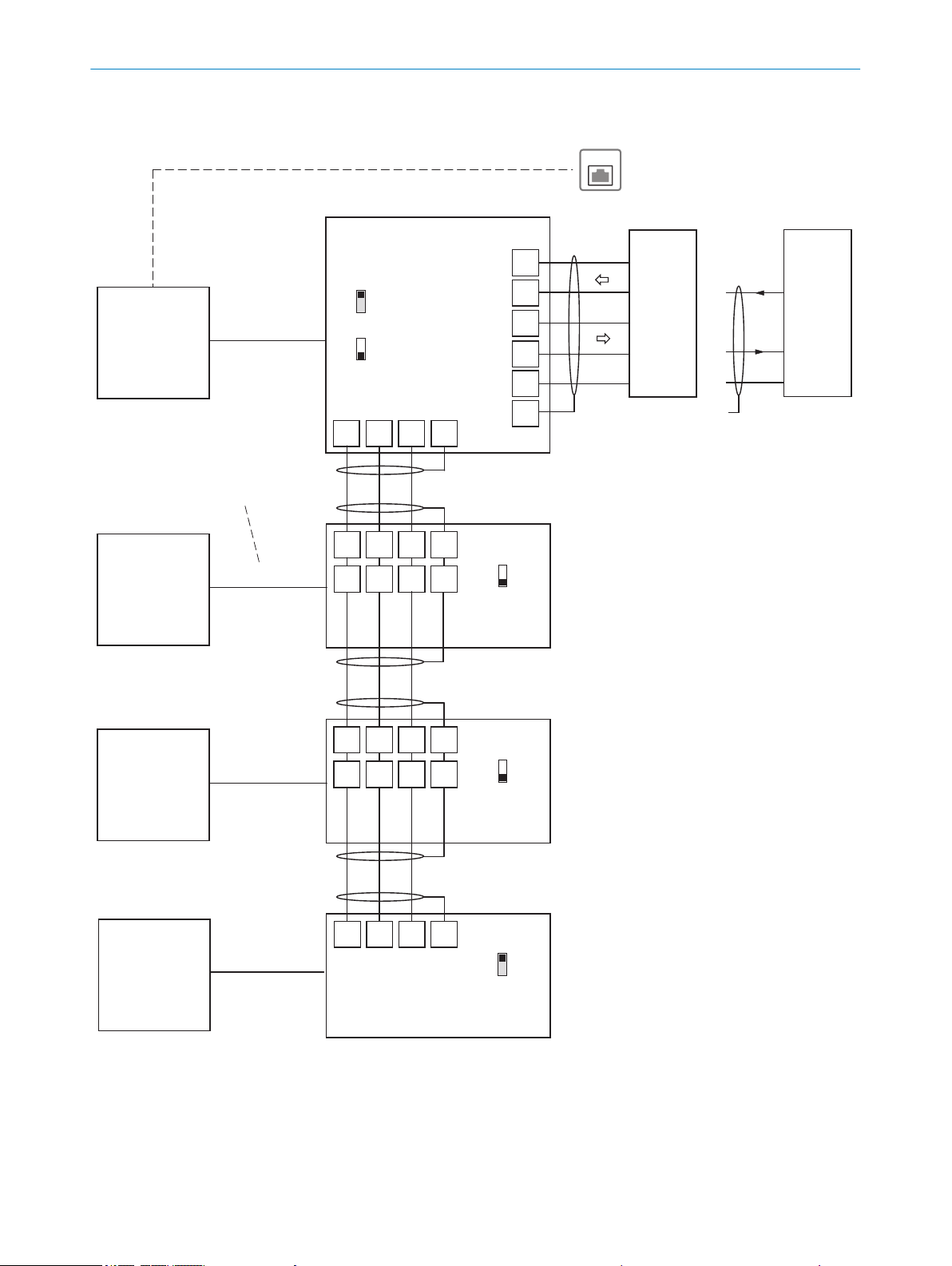
EthernetEthernet
HostHost
Shield
1) Cable no. 2020302 (3m) at
“HOST/AUX” connection
24
25
34
35
7
CDM490-0001
(Basic card)
CDM490-0001
(Basic card)
CDM490-0001
(Basic card)
CLV69x
CLV69x
CLV69x
(Slave)
(Slave)
(Slave)
GN = 01
CLV69x
(Master)
GN = 63
GN = 02
GN = 03
(max. 32 participants)
Branch line
Switch
ON
OFF
S4 (TermCAN):
Switch
ON
OFF
S4 (TermCAN):
Switch
ON
OFF
S4 (TermCAN):
21 22 23 6
21 22 23 6
31 32 33 7
21 22 23 6
21 22 23 6
31 32 33 7
CAN_H
CAN_L
Shield
GND
CAN_H
CAN_L
Shield
GND
CAN_H
CAN_L
Shield
GND
CAN_H
CAN_L
Shield
GND
GND
GND
GND
RxD
TxD
TD‒
RD‒
RD+
TD+
RS-232RS-422
T‒/TxD
R‒/RxD
T+
R+
26
Connecting cable
1)
Connecting cable
1)
Connecting cable
1)
Connecting cable
1)
CAN
CAN
CAN
CAN 1,
among
others
CAN 1,
among
others
CAN 1,
among
others
CAN 1,
among
others
Connection and looping of the supply
voltage and connection of the read
cycle sensor, e.g. to host, is neglected
here.
Switch
ON
OFF
S4 (TermCAN):
Serial host interface
Ethernet (Host Port)
ON
OFF
S2 (RS485):
Wire CLV69x in the CDM490-0001 connection module for SICK CAN SENSOR network
CAN_H = CAN1_H CLV69x
CAN_L = CAN1_L CLV69x
S4 (TermCAN = TermCAN1)
CDM490-0001
(Basic card)
ELECTRICAL INSTALLATION
6
Figure 74: Wiring the CAN interface
80
O PE R AT I NG IN S TR U CT I ON S | CLV69x 8014396/ZMG8/2017-07-04 | SICK
Subject to change without notice
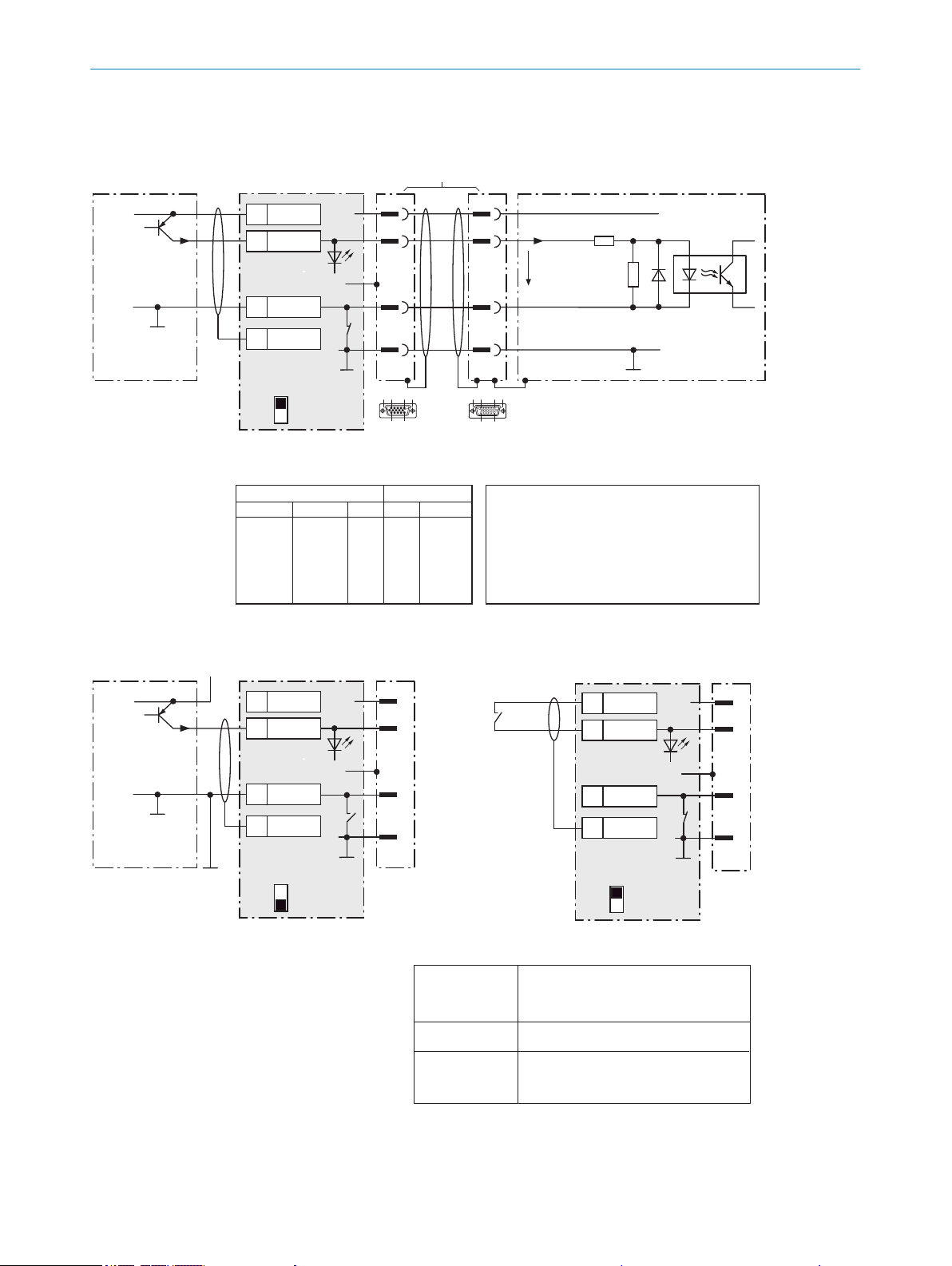
Wire “Sensor 1 ... 6” switching inputs of the CLV69x in the CDM490-0001 connection module
CLV69x
PNP sensor
U
V
U
V
U
V
GND
GND
SensGND
3,32K
6,64K
Sensor Z
U
e
9
a) Schema: sensor supplied by CDM490-0001
b) Schema: sensor connected volt-free and externally supplied
d) Schema: switch connected volt-free
and externally supplied
1
Y
9
Y
5
1
5
Out
+24V*
+24V*
GND
S1
e.g. photoelectric sensor
PNP sensor
UV
GND
Connection of the switch as under b)
Out
GND
S1
e.g. photoelectric
sensor
ON
OFF
S1 : SGND
ON
OFF
S1 : SGND
U
V ext
Characteristic data of the switching inputs “Sensor 1 ... 6”
Current at the input starts the
assigned function, e.g. start reading cycle.
(CLV69x default settings:
logic active high, debouncing 10mm)
– Opto-decoupled, reverse-polarity protected
– Can be wired with PNP output of a sensor
Low: Ue ≤ 2V; Ie ≤ 0,3mA
High: 6V ≤ Ue ≤ 32V;
0,7mA ≤ Ie ≤ 5mA
Switching behavior
Properties
Electrical values
Switch S1: SGND
ON: connect GND of the switching inputs to the
GND of the CDM490-0001/CLV69x.
OFF: sensors connected volt-free to switching inputs
on the CDM490-0001/CLV69x.
Reference potential valid for all “Sensor 1 ... 6”
switching inputs and optionally
Shield
1) E.g. no. 2020302 (3m)
GND
.
.
.
Shield
X
Name
54
SGND
6
Shield
51
+24V*
X
Name
54
SGND
6
Shield
51
+24V*
Ue = max. 32V
a) Schema: switch supplied by CDM490-0001
+24V*
GND
S1
ON
OFF
S1 : SGND
Shield
X
Name
54
SGND
6
Shield
51
+24V*
2 “I/O” connection
2
6
1
10
5
11
15
10 5 61
15 11
15-pin
D-Sub-HD
male connector
15-pin
D-Sub-HD
female connector
CDM490-0001 CLV69x
Terminal X
61
62
63
64
65
66
Name
Sensor
IN 0
IN 1
IN 2
IN 3
IN 4
Pin Y
3
6
2
7
11
12
Pin Y
3
6
2
7
11
12
Sensor Z
Sensor 1
Sensor 2
Sensor 3
Sensor 4
Sensor 5
Sensor 6
CDM490-0001
(I/O card)
CDM490-0001
(I/O card)
CDM490-0001
(I/O card)
Adapter cable
1)
ELECTRICAL INSTALLATION
6
Figure 75: Wiring switching inputs “Sensor 1 to 6”
8014396/ZMG8/2017-07-04 | SICK O PE R AT I NG IN S TR U CT I ON S | CLV69x
Subject to change without notice
81
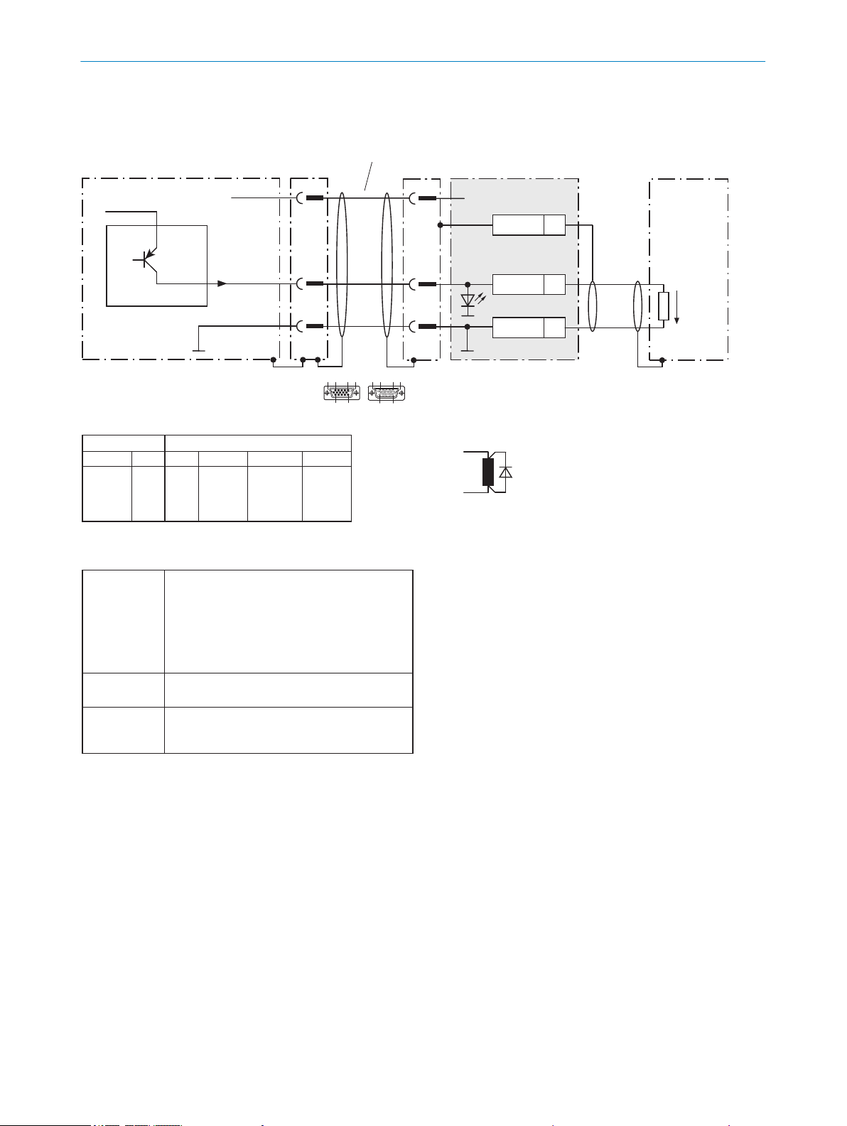
Wire “Result 1 ... 4” switching outputs of the CLV69x in the CDM490-0001 connection module
CLV69x
CDM490-0001
(I/O card)
UV = DC 18 ... 30V
Load (e.g. PLC)
Cable, e.g.
No. 2020302 (3m)
Y
5
.
.
.
Z
Name
45
GND
5
Shield
+24V* (UV)
U
V
GND
Sweep-out circuit:
Attach a freewheeling diode
directly to the load.
With inductive load:
Ua
Result X
Result X
GND
Y
5
1 1
Characteristic data of “Result 1 ... 4“ switching outputs
PNP switching to supply voltage
UV (+24V*).
CLV69x default settings:
Result 1: device ready (static), logic: active high
Result 2: good read, 100mm, logic: active high
Result 3: no function assigned
Result 4: no function assigned
– Short-circuit protected + temperature protected
– Not electrically isolated from UV (+24V*)
0V ≤ Ua ≤ U
V
Guaranteed:
(UV − 1.6V) ≤ Ua ≤ UV at Ia ≤ 100mA
Switching
behavior
Properties
Electrical
values
2 “I/O” connection
2
6
1
10
5
11
15
10 5 61
15 11
D-Sub-HD
CDM490-0001CLV69x
Terminal Z
41
42
43
44
Name
Result 1
Result 2
Result 3
Result 4
Pin Y
4
8
10
15
Pin Y
4
8
10
15
Result X
Result 1
Result 2
Result 3
Result 4
Result X
Result 1
Result 2
Result 3
Result 4
ELECTRICAL INSTALLATION
6
Figure 76: Wiring switching outputs “Result 1 to 4”
82
O PE R AT I NG IN S TR U CT I ON S | CLV69x 8014396/ZMG8/2017-07-04 | SICK
Subject to change without notice

7 Commissioning
7.1 Overview of the commissioning steps
– Commissioning of the device with factory default
– Installing the SOPAS ET configuration software
– Connection of the device to PC/notebook with the SOPAS ET configuration soft‐
ware
– Adjustment and configuration of the device to optimize functionality
– Test of the device for correct functionality in read operation
7.2 SOPAS ET configuration software
The SOPAS-ET configuration software can be used to adjust the device to the reading
situation on location. The configuration data is stored and archived as a parameter set
(project file) on the PC.
7.2.1 Functions of the SOPAS-ET configuration software for the device (overview)
The general functions of the software and its operation are described in the online help
in the SOPAS ET configuration software:
COMMISSIONING 7
– Choice of the menu language (German, English)
– Setting up communication with the device
– Password-protected configuration for different operating levels
– Recording of the data in continuous operation (recording and analyzing data of
certain memory areas of the device with the data recorder)
– Diagnostics for the system
7.2.2 Installing SOPAS ET
NOTE
The configuration software SOPAS ET, the current system prerequisites for the PC, and
the instructions for downloading can be found online at:
www.sick.com/SOPAS_ET
b
1. Start the PC and download the latest version at www.sick.com/SOPAS_ET .
2. If installation does not start automatically, launch setup.exe from the download
directory.
3. Follow the operating instructions to complete the installation.
7.3 Start the SOPAS ET configuration software and connect to the device
1. Electrically connect a device data interface with a PC that can connect to the Inter‐
net.
2. In accordance with the instructions, download and install the latest version of the
SOPAS ET configuration software, as well as the current device description file
(*.sdd) for the device.
In this case, select the “Complete” option as proposed by the installation wizard.
Administrator rights may be required on the PC to install the software.
3. Start the “SOPAS ET” program after completing the installation.
Path: Start > Programs > SICK > SOPAS ET Engineering Tool > SOPAS.
8014396/ZMG8/2017-07-04 | SICK O PE R AT I NG IN S TR U CT I ON S | CLV69x
Subject to change without notice
83
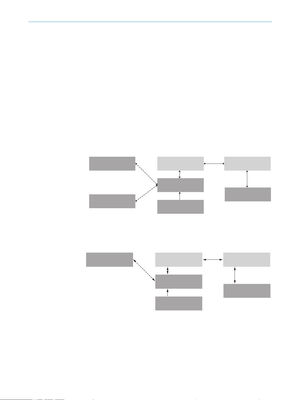
Cloning plug
PROM
PROM
ROM
PROM
RAM
RAM
Database
(Hard drive)
Bar code scanner
PC with SOPAS-ET
configuration software
Permanently saved
parameter set
Parameter set in the
working memory of the
bar code scanner
Permanently saved
parameter set
Saved project file (*.sopas)
with archived parameter set
Permanently saved
parameter set
Factory default of the
bar code scanner
Opened project file with
current parameter set
Parameter memory module
CMC600
‒ and/or (optional) ‒
Parameter set in the
main memory of the
device 6
Permanently saved
parameter set of the
device 5
Factory default setting of
the device 7
Device 2Optional: 1 PC with SOPAS ET
Configuration Software 3
Parameter memory module
CMC600 4
Volatile memory à
Opened project file
with current parameter
set of the device 8
Volatile memory à
Non-volatile memory ß
Non-volatile memory ß
Saved project file (*.sopas)
with archived parameter
set of the device 9
Data base on e. g. hard drive
(non-volatile memory) á
Permanently saved
parameter set of the
device 5
Non-volatile memory ß
7 COMMISSIONING
4. Establish a connection between SOPAS ET and the device with the wizard that has
already launched automatically.
In order to do this, select the device from the devices available depending on the
connected communication interface, e.g. Ethernet (default Ethernet address: IP
address: 192.168.0.1, subnet mask: 255.255.255.0, baud rate: 57600 with
serial connection).
✓
SOPAS ET establishes communication with the device and loads the associated
device description file. The device project tree opens.
7.4 Initial commissioning
The device is adjusted to the reading situation on site using the SOPAS ET configuration
software. The starting point for this is the default factory settings, which can be
adjusted to optimize the device. In order to do this, the SOPAS ET configuration soft‐
ware is used to create an application-specific parameter set, which can be loaded per‐
manently into the device and saved and archived as a project file (Sopas file with con‐
figuration data) on the PC.
84
Figure 77: Saving the parameter set and configuration with SOPAS ET
Figure 78: Saving the parameter set and configuration with SOPAS ET
Optional
1
Device
2
O PE R AT I NG IN S TR U CT I ON S | CLV69x 8014396/ZMG8/2017-07-04 | SICK
PC with SOPAS ET configuration software
3
CMC600 parameter memory module
4
5
6
7
Permanently saved device parameter set
Parameter set in the working memory of the device
Factory-set defaults for the device
Subject to change without notice

8
9
ß
à
á
If the device is connected to a CDB/CDM connection module with the CMC600 parame‐
ter memory module, the parameter set is also stored on the card or permanently in the
module with every save.
The device also saves its configuration data in an external parameter memory of the
cloning plug. Whenever the device is restarted, it loads the parameter set automatically
from the cloning plug into its permanent memory. This means, for example, that a
device can be replaced without losing configuration data. If a CMC600 is also available,
then the device takes the parameter set from the CMC600.
7.5 Adjust the device
For complete adjustment of the device, the electrical installation must be complete and
the device must have been commissioned.
COMMISSIONING 7
Opened project file with current device parameter set
Saved project file with archived device parameter set
Nonvolatile memory
Volatile memory
Database on the hard drive, for example (nonvolatile memory)
1. Loosen the bracket screws so that the device can be aligned.
2. Align the device so that the angle between the scanning line and the bar code
stripes is almost 90°.
3. To prevent interference reflections, arrange the device as close to being plane-par‐
allel to the object surface as possible.
4. Manually place objects with bar codes one after the other into the reading range
of the device, see "Technical data", page 96.
5. Check the reading result with the SOPAS ET configuration software.
6. When doing so, place objects at different positions (angles) in the reading field
and ensure that the limit values for the permitted reading angles are not
exceeded, see "Angle alignment of the device", page 24.
7. Align the device so that the good read rate is between 70% and 100%.
8. Tighten the screws on the device.
7.6 Fine adjustment and further configuration
NOTE
The other settings and the fine adjustment depend on the relevant application situa‐
tion.
User level, parameter download to the device
The user is automatically logged into the device in the “Authorized customer” level and
can change parameters which are immediately transmitted to the device (default set‐
ting).
Configuration via “Quickstart”
The “Quickstart” tab offers an overview of the most important parameters and enables
quick evaluation of code content. Functions such as evaluation window, percentage
evaluation, code configuration, and adjusting tool are available via the Quickstart.
Application wizard
The application wizard (“Wand” icon) supports device configuration both as a standalone device and as a master or as a slave for a master/slave combination based on
the CAN bus.
8014396/ZMG8/2017-07-04 | SICK O PE R AT I NG IN S TR U CT I ON S | CLV69x
Subject to change without notice
85
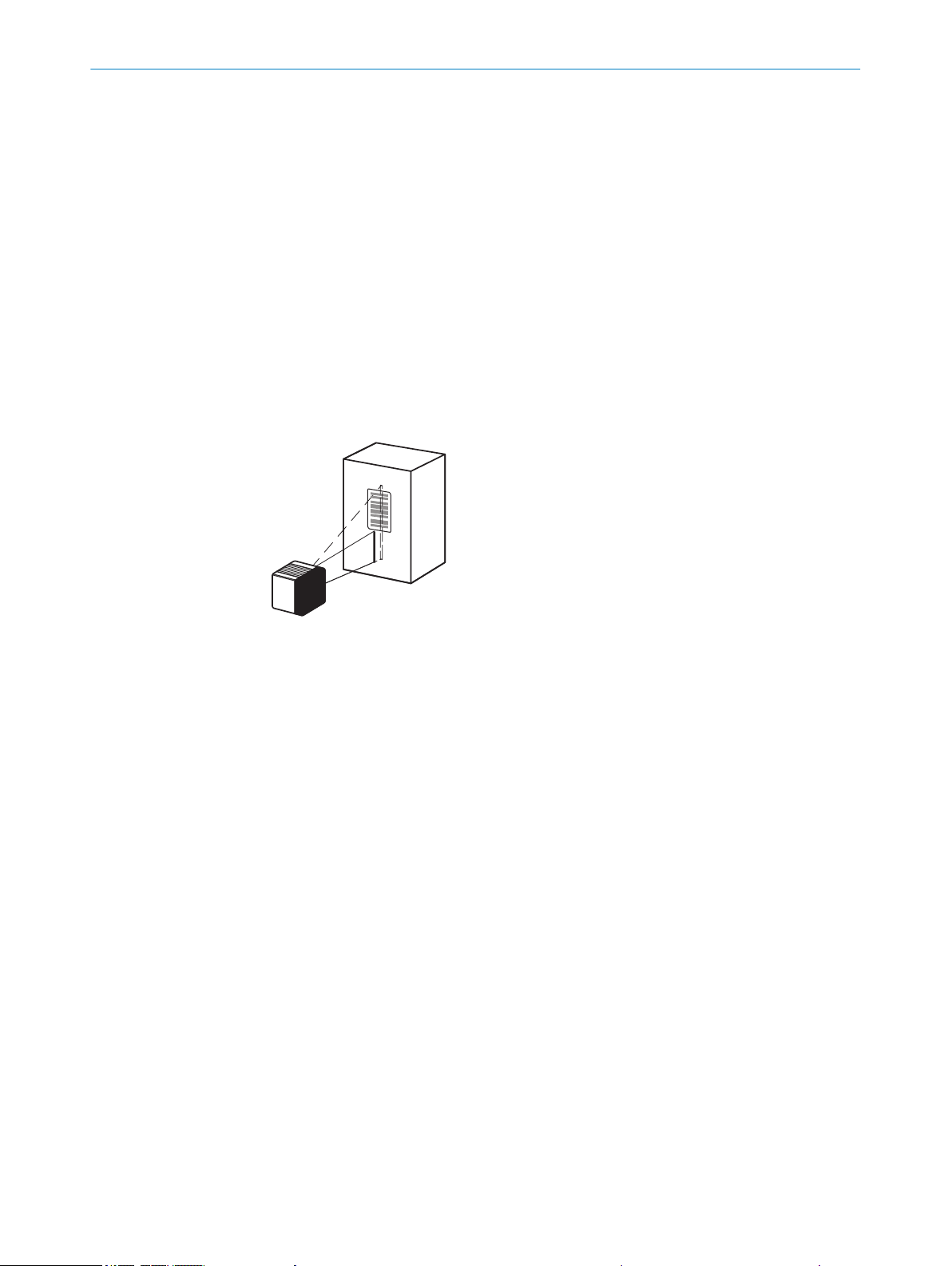
7 COMMISSIONING
Evaluation window
The evaluation window shows the code content, the object index, the code type, the
code security, and the device number of the reading device.
Percentage evaluation
The percentage evaluation permanently assesses the quality of the reading. Bar codes
are not assessed. Here, the bar codes must not be subjected to any conveying move‐
ment. The device performs 100 scans in each case and evaluates the reading quality.
The device continuously emits read results every 2 s via the AUX interface, together
with the read diagnostic data. A timer starts when percentage evaluation is called. If a
manual abort is not carried out, the device automatically returns to read mode after
5 min.
Adjusting Tool
The “Adjusting Tool” operating mode supports optimal placing of the center of the scan
line on the object. To do this, the device hides half of the scan line.
Figure 79: Appearance of the scan line in “Adjusting Mode”
This function is only available under adjustment mode in Quickstart in the “Authorized
customer” level.
Code configuration
In the factory default setting, the device decodes the following code types:
Code 39
•
2/5 interleaved
•
Code 128 family
•
You can activate further code types and set other decoder properties (Device Tree >
Parameters > Code Configuration).
Scanning frequency
You can set the scanning frequency in the range from 400 Hz to 1200 Hz (Device Tree
> Parameters > Reading Configuration).
Focus setting
In the factory default setting, the device works with auto focus. Alternatively, the device
can be operated in the modes “Dynamic Focus” and “Fixed Focus” (Device tree >
Parameters > Reading configuration > Focus control).
Ethernet interface
86
Use the “Ethernet” page to make adaptations to the IP address and the subnet mask
(Device tree > Parameters > Network/Interfaces/IOs > Ethernet).
O PE R AT I NG IN S TR U CT I ON S | CLV69x 8014396/ZMG8/2017-07-04 | SICK
Subject to change without notice

COMMISSIONING 7
Object trigger control
If the device is to be operated with an additional read pulse sensor, for example, a pho‐
toelectric sensor on the “Sensor 1” switching input, select the setting “Sensor 1”
(Device tree > Parameters > Object trigger control).
Test and, if necessary, modify the specified settings when operating the system under
real conditions.
8014396/ZMG8/2017-07-04 | SICK O PE R AT I NG IN S TR U CT I ON S | CLV69x
Subject to change without notice
87

Ready
Result
Laser
Data
CAN
LNK TX
Read Diagn
Teach-in
Auto-Setup
Adjusting
User-defined
100
[%]
1
2
O
O
O
O
O
Ö
Ö
Ö
O
Ö
O
8 OPERATION
8 Operation
8.1 Optical displays and control elements
Figure 80: LED status indicators, bar graph and function buttons
Arrow pushbutton
1
Return pushbutton
2
Table 10: Illumination behavior of the LED status display
Display LED Status
Ready
green Lights up constantly after switching on and completion of success‐
ful self-test
The device is ready for reading
Goes out when downloading or uploading configuration data
red Hardware fault
Result
Laser
Data
CAN
LNK TX
= illuminated, Ö = flashing
green Successful reading
green Laser on
green Data output via host interface
green Data transmission via CAN interface, status of the internal termi‐
nation of the cloning plug: all existing terminations are not active,
or not available (depending on the plug)
blue Data transmission via CAN interface, status of the internal termi‐
nation of the cloning plug: all existing terminations are active
purple Data transmission via CAN interface, status of the internal termi‐
nation of the cloning plug: not all existing terminations are active
green Physical Ethernet connection
green Data traffic via Ethernet
Operating button and status displays on the second display level
The two pushbuttons 1 and 2 are used to call up device functions manually without
using a PC. The second display level of the LEDs signals the selectable functions. Cur‐
rently, “Read Diagn” (percentage evaluation) and “Adjusting” (adjusting tool) are availa‐
ble.
88
1. Press the return key for approx. 2 seconds. The device switches to operating mode
of the pushbutton. “Ready” LED now lights up blue.
2. Press arrow key repeatedly to select the desired function (LED lights up blue).
O PE R AT I NG IN S TR U CT I ON S | CLV69x 8014396/ZMG8/2017-07-04 | SICK
Subject to change without notice

3. Press the return key to confirm the selected function.
The device executes the function and automatically returns to the read mode after
2 minutes.
4. To abort the function manually (cancel), press the Return key again and hold for
2 seconds.
Bar Graph 0 ... 100%
In “Percentage Evaluation” operating mode, the bar graph continuously displays the last
determined read rate in %, in each case related to 100 readings. The bar graph is deac‐
tivated in standard read mode.
8.2 Operating options
The device can be configured according to application in the following manner:
■
Locally at the device with the SOPAS ET configuration software: Protection of the
parameter set as a configuration file on the PC in SOPAS ET. Access to the device
via AUX interface (USB or Ethernet).
■
As an alternative to the SOPAS ET configuration software, command strings are
available, upon which the operator interface of the configuration software is also
based. These are also for the triggering of device functions (e.g. reading). Docu‐
ments on the commando strings can be obtained from SICK on request.
OPERATION 8
The SOPAS ET configuration software is used for device diagnostics in case of a fault.
In normal operation, the device operates fully automatically.
8014396/ZMG8/2017-07-04 | SICK O PE R AT I NG IN S TR U CT I ON S | CLV69x
Subject to change without notice
89

9 MAINTENANCE
9 Maintenance
9.1 Maintenance
During operation, the device works maintenance-free.
Depending on the assignment location, the following preventive maintenance tasks
may be required for the device at regular intervals:
NOTE
No maintenance is required to ensure compliance with the laser class.
Table 11: Maintenance schedule
Maintenance work Interval To be carried out
Clean housing and front screen Cleaning interval depends on ambi‐
Check the screw connections and
plug connections
ent conditions and climate
Interval depends on the place of use,
ambient conditions, or operational
regulations. Recommended: At least
every 6 months.
by
Specialist
Specialist
9.2 Cleaning
9.2.1 Cleaning the device
At regular intervals (e.g. weekly), check the reading window and the housing of the
device for contamination. This is especially relevant in harsh operating environments
(dust, abrasion, damp, fingerprints, etc.). The reading window lens must be kept clean
and dry during operation.
NOTICE
Equipment damage due to improper cleaning.
Improper cleaning may result in equipment damage.
■
■
Cleaning the reading window
NOTICE
Damage to the Reading Window!
Reduced reading performance due to scratches or streaks on the reading window.
b
b
b
b
Only use recommended cleaning agents.
Never use sharp objects for cleaning.
Clean the reading window only when wet.
Use a mild cleaning agent that does not contain powder additives. Do not use
aggressive cleaning agents, such as acetone, etc.
Avoid any movements that could cause scratches or abrasions on the reading win‐
dow.
Only use cleaning agents suitable for the screen material.
90
The type of screen material used in the reading window can be found on the type label,
see "Type code", page 12.
O PE R AT I NG IN S TR U CT I ON S | CLV69x 8014396/ZMG8/2017-07-04 | SICK
Subject to change without notice

MAINTENANCE 9
NOTE
Static charge causes dust particles to adhere to the reading window. This effect can be
avoided by using an anti-static glass cleaner in combination with the SICK lens cloth
(can be obtained from www.sick.com).
Cleaning procedure:
CAUTION
Optical radiation: Laser class 2
The human eye is not at risk when briefly exposed to the radiation for up to 0.25 sec‐
onds. Exposure to the laser beam for longer periods of time may cause damage to the
retina. The laser radiation is harmless to human skin.
■
Do not look into the laser beam intentionally.
■
Never point the laser beam at people's eyes.
■
If it is not possible to avoid looking directly into the laser beam, e.g., during com‐
missioning and maintenance work, suitable eye protection must be worn.
■
Avoid laser beam reflections caused by reflective surfaces. Be particularly careful
during mounting and alignment work.
■
Do not open the housing. Opening the housing will not switch off the laser. Open‐
ing the housing may increase the level of risk.
■
Current national regulations regarding laser protection must be observed.
Switch off the device for the duration of the cleaning operation. If this is not possi‐
b
ble, use suitable laser protection goggles. These must absorb radiation of the devi‐
ce's wavelength effectively.
Glass lens: Remove dust from the reading window using a soft, clean brush. If nec‐
b
essary, also clean the reading window with a clean, damp, lint-free cloth, and a
mild anti-static glass cleaning agent.
Plastic lens: Clean the reading window only with a clean, damp, lint-free cloth, and
b
a mild anti-static glass cleaning agent.
NOTE
If the reading window is scratched or damaged (cracked or broken), the lens must be
replaced. Contact SICK Service to arrange this.
Cleaning the housing
In order to ensure that heat is adequately dissipated, the housing surface must be kept
clean.
Clear the build up of dust on the housing with a soft brush.
b
9.2.2 Cleaning surfaces that have an optical effect
Depending on how the reading station is equipped, additional local sensors may have
other surfaces with an optical effect installed (e.g. single-beam photoelectric safety
switches for an external reading pulse). Contamination on these sensors can result in
faulty switching behavior.
8014396/ZMG8/2017-07-04 | SICK O PE R AT I NG IN S TR U CT I ON S | CLV69x
Subject to change without notice
91

9 MAINTENANCE
To avoid faulty switching behavior, remove contamination from the optical effect
b
surfaces of external sensors.
Figure 81: Cleaning the external optical sensors (read pulse encoder)
92
O PE R AT I NG IN S TR U CT I ON S | CLV69x 8014396/ZMG8/2017-07-04 | SICK
Subject to change without notice

10 Troubleshooting
10.1 Overview of possible errors and faults
Table 12: Errors and faults
Situation Error/fault
Mounting
Electrical installation
Configuration
Operation
■
■
■
■
■
■
■
■
■
TROUBLESHOOTING 10
Device poorly aligned to the object with the bar code (e.g.
dazzle).
Read cycle sensor incorrectly positioned (e.g., internal read‐
ing interval is opened too early or closed too late).
Incremental encoder incorrectly positioned.
Data interfaces of the device incorrectly wired.
Functions not adapted to local conditions, e.g. parameters
for the data interface not set correctly.
Device limits not observed, e.g. reading distance, aperture
angle.
Read cycle trigger source not selected correctly.
Read cycle control incorrect and/or not suitable for the
object.
Device faults (hardware/software).
10.2 Detailed fault analysis
10.2.1 LEDs on the device
The conditions that can be read from the device LEDs on the sensor housing (see "Opti‐
cal displays and control elements", page 88) include:
■
Operational readiness (Ready)
■
Reading result status (Good Read or No Read)
■
Hardware fault
■
Firmware download status
■
Connection status of the device
The LED display can indicate any errors or faults with this. Further information for this
can be found in the system information.
10.2.2 System information
The device outputs faults in different ways. Fault output is staggered and thus allows
for an increasingly detailed level of analysis.
Communication errors can occur when transmitting data to the device. The device
•
then returns a fault code.
For faults that occur during reading, the device writes fault codes in the status log
•
(see "Status log", page 93).see "Status log", page 93.
10.3 Status log
NOTE
The status log is retained even after switching the device off and on again.
The device distinguishes between four types of fault:
■
Information
■
Warning
8014396/ZMG8/2017-07-04 | SICK O PE R AT I NG IN S TR U CT I ON S | CLV69x
Subject to change without notice
93

10 TROUBLESHOOTING
■
Error
■
Critical fault
The device saves only the last five entries for each fault type.
10.3.1 Displaying the status log
To display the status log, the SOPAS ET configuration software must be connected with
the device online.
1. Connect the SOPAS ET configuration software to the device.
2. Open CLV6xx in the project tree: Service > System Status > System Information
tab.
10.4 SICK Support
If a fault cannot be rectified, the device may be defective.
The device must not be repaired by the user. Interrupting or modifying the device will
invalidate any warranty claims against SICK AG.
Rapid replacement of a device by the user is, however, possible, see "Disassembly and
disposal", page 95.see "Disassembly and disposal", page 95.
Where a fault cannot be rectified, make contact with the SICK Service department.
b
To find your agency, see the final page of this document.
NOTE
Before calling, make a note of all type label data such as type designation, serial num‐
ber, etc. to ensure faster telephone processing.
94
O PE R AT I NG IN S TR U CT I ON S | CLV69x 8014396/ZMG8/2017-07-04 | SICK
Subject to change without notice

11 Decommissioning
11.1 Disassembly and disposal
Dismantling the device
1. Switch off the supply voltage to the device.
2. Detach all connecting cables from the device.
3. If the device is being replaced, mark its position and alignment on the bracket or
surroundings.
4. Remove the device from the bracket.
5. Unscrew the screws for the cloning plug and remove the cloning plug.
6. Apply protective covering to the cloning plug.
Disposing of the device
Any device which can no longer be used must be disposed of in an environmentally
friendly manner in accordance with the applicable country-specific waste disposal regu‐
lations. As they are categorized as electronic waste, the device must never be disposed
of with household waste.
11.2 Returns
DECOMMISSIONING 11
Do not dispatch devices to the SICK Service department without consultation.
b
NOTE
To enable efficient processing and allow us to determine the cause quickly, please
include the following when making a return:
■
Details of the contact person
■
Description of the application
■
Description of the fault that occurred
8014396/ZMG8/2017-07-04 | SICK O PE R AT I NG IN S TR U CT I ON S | CLV69x
Subject to change without notice
95
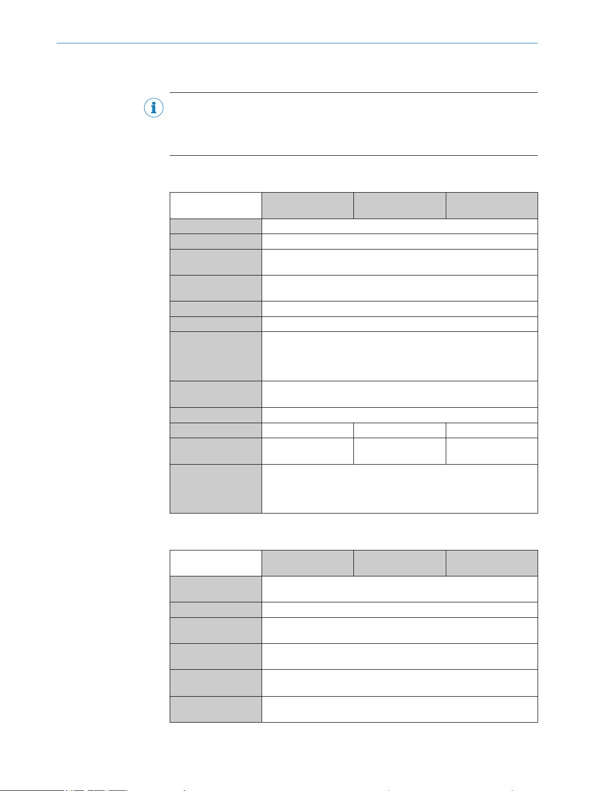
12 TECHNICAL DATA
12 Technical data
NOTE
The relevant online data sheet for your product can be downloaded, saved, and printed,
including technical data, dimensions, and connection diagrams:
www.sick.com/CLV69x
b
12.1 Optics
CLV690-0/1 Standard
Density
Focus Auto focus, alternative: dynamic focus setting or fixed focus
Focus trigger source Data interface/switching inputs
No. of distance config‐
urations
Focus adjustment
time
Light source Visible red light (660 nm)
MTBF 100,000 h
Laser class Class 2 according to EN/IEC 60825-1:2014
Aperture angle Front-end: ≤ 60°
Scanning frequency 400 Hz ... 1200 Hz
Code resolution 0.25 mm ... 1.0 mm 0.35 mm ... 1.2 mm 0.17 mm ... 0.4 mm
Reading distance 500 mm ... 2100 mm 500 mm ... 2200 mm 400 mm ... 1600 mm
Oscillating mirror
functions
≤ 8
≤ 20 ms
Identical laser class for issue EN/IEC 60825-1:2007
Complies with 21 CFR 1040.10 except for tolerances according to
Laser Notice no. 50 from June 24, 2007
Oscillating mirror: ≤ 50°
Fixed (adjustable position), oscillating (variable or fixed amplitude),
one-shot
Oscillation frequency: 0.5 Hz ... 4 Hz
Angle of deflection: -20° ... 20° (can be adjusted using software)
CLV691-0/1 Low Den‐
sity
CLV692-0/1 High
Density
(type-dependent)
12.2 Performance
96
O PE R AT I NG IN S TR U CT I ON S | CLV69x 8014396/ZMG8/2017-07-04 | SICK
CLV690-0/1 Standard
Density
Bar code types 2/5 Interleaved, Codabar, Code 128, Code 39, Code 93, GS1-128/EAN
128, UPC/GT IN/EAN
Print ratio 2:1 ... 3:1
Bar code print con‐
trast (PCS)
Ambient light immun‐
ity
No. of codes per scan 1 ... 20 (standard decoder)
No. of codes per read‐
ing interval
≥ 60%
2000 lx, on bar code
1 ... 6 (SMART decoder)
1 ... 50 (auto-discriminating)
CLV691-0/1 Low Den‐
sity
CLV692-0/1 High
Density
Subject to change without notice
TECHNICAL DATA 12
12.3 Interfaces
CLV690-0/1 Standard
Density
No. of characters per
reading interval
No. of multiple read‐
ings
Serial (RS-232,
RS-422/-485)
Ethernet Only with cloning plug 2062452, 2074708 and 2074710
CAN bus Function: SICK CAN sensor network (Master/Slave, Multiplexer/Server)
PROFIBUS DP Optional via external fieldbus module (CDF 600-21xx)
DeviceNet Optional via external connection module (CDM + CDF)
Switching inputs Cloning plug no. 2062450: 6x
Switching outputs Cloning plug no. 2062450: 4x
Reading pulse Switching inputs, serial interface, auto pulse, CAN
Optical displays 6 LEDs (Ready, Result, Laser, Data, CAN, LNK TX)
Operating elements 2 buttons
Parameter memory Automatic via cloning plug
Configuration soft‐
ware
5000
1 ... 100
CLV690-0/1 Standard
Density
Only with cloning plug 2062450, 2062452, 2062453 and 2062454
Function: Host, AUX (only RS-232)
Data transmission rate: 300 Baud ... 500 kBaud, AUX: 57.6 kBaud
(RS-232)
Function: Host, AUX
Data transmission rate: 10/100 Mbit/s
Protocol: TCP/IP, EtherNet/IP, PROFINET (optionally via external field‐
bus module CDF 600-22xx), PROFINET DualPort (optionally via external
fieldbus module CDF 600-22xx)
Data transmission rate: 20 kbit/s ... 1 Mbit/s
Protocol: CSN (SICK CAN Sensor Network)
Cloning plug no. 2062452: 2x
Ue = max. 30 V; Ie = max. 5 mA
Opto-decoupled, reverse polarity protected, adjustable debounce time
Cloning plug no. 2062452: 4x
Ua = UV – 1.6 V, Ia ≤ 100 mA (typical)
Short-circuit protected, temperature protected, not electrically isolated
from the supply voltage
Bar graph for displaying the reading rate percentage (10 LEDs)
Alternatively also via an optional CMC600 cloning module in the
CDB/CDM connection module
SOPAS ET
CLV691-0/1 Low Den‐
sity
CLV691-0/1 Low Den‐
sity
CLV692-0/1 High
Density
CLV692-0/1 High
Density
12.4 Mechanics/electronics
CLV690-0/1 Standard
Density
Electrical connection 60-pin system connection for connecting a cloning plug
8014396/ZMG8/2017-07-04 | SICK O PE R AT I NG IN S TR U CT I ON S | CLV69x
Subject to change without notice
CLV691-0/1 Low Den‐
sity
CLV692-0/1 High
Density
97
12 TECHNICAL DATA
CLV690-0/1 Standard
Density
CLV691-0/1 Low Den‐
sity
CLV692-0/1 High
Density
Supply voltage Device without heating:
18 V DC ... 30 V DC (type-dependent), LPS or NEC Class 2, SELV as per
currently valid EN 60950-1, reverse polarity protected
Device with heating:
21.6 V DC ... 28.8 V DC (type-dependent), LPS or NEC Class 2, SELV as
per currently valid EN 60950-1, reverse polarity protected
Power consumption
(with unloaded out‐
puts)
Device without heating (I
max
= 1 A):
Line scanner (LS): typ. 15 W
LS with oscillating mirror: typ. 17 W
Device with heating (I
max
= 4 A):
Line scanner (LS): typ. 78 W
LS with oscillating mirror: typ. 80 W
Housing/reading win‐
dow
Aluminum die cast/glass
(optional) plastic (CLV690-0010)
Housing color Light blue (RAL 5012)
Electrical safety as per UL 60950-1 certification
Safety EN 60950-1: 2006-04/A11: 2009-03/A1: 2010-03/A12: 2011:02
Weight Line scanner: 1500 g
Line scanner with oscillating mirror: 2200 g
Dimensions (L x W xH)Front-end: 117 mm x 117 mm x 94 mm
Oscillating mirror: 182 mm x 128 mm x 97 mm
Enclosure rating IP 65
12.5 Ambient data
Interference emission EN 61000-6-4: 2007-01/A1: 2011-02
Immunity to electrical
noise
Vibration resistance EN 60068-2-6: 2008-02
Shock resistance EN 60068-2-27: 2009-05
Ambient operating
temperature
Storage temperature -20 °C ... +70 °C
Permissible relative
humidity
12.6 Reading field diagrams
12.6.1 Reading field conditions
Test code Code 128
Print contrast >90%
Tilt ±45°
Ambient light <2000 lx
Good read rate >75%
CLV690-0/1 Standard
Density
CLV691-0/1 Low Den‐
sity
EN 61000-6-2: 2005-08
Device without heating:
0 °C ... +40 °C
Device with heating:
-35 °C ... +35 °C
0% ... 90%, non-condensing
CLV692-0/1 High
Density
98
O PE R AT I NG IN S TR U CT I ON S | CLV69x 8014396/ZMG8/2017-07-04 | SICK
Subject to change without notice
TECHNICAL DATA 12
NOTE
Min. and max. reading distances are measured radially from the device.
12.6.2 Overview of reading field diagrams
Scanning procedure: line scanner
CLV69x type Resolution Diagram Page
CLV690-0xxx Standard
Density
CLV691-0xxx Low Density Reading field height/tilt over reading distance for resolution 0.50 mm page 111
CLV692-0xxx High Density Reading field height/resolution over reading distance page 116
Reading field height/resolution over reading distance page 100
Min. and max. reading distance (DOF) for resolution 0.35 mm/aperture angle 40° page 101
Min. and max. reading distance (DOF) for resolution 0.35 mm/aperture angle 56° page 101
Min. and max. reading distance (DOF) for resolution 0.50 mm/aperture angle 40° page 103
Min. and max. reading distance (DOF) for resolution 0.50 mm/aperture angle 56° page 104
Scanning frequency characteristic curve page 105
Min. and max. reading distance (DOF) for resolution 0.50 mm/aperture angle 40° page 112
Min. and max. reading distance (DOF) for resolution 0.50 mm/aperture angle 60° page 113
Scanning frequency characteristic curve page 114
Min. and max. reading distance (DOF) for resolution 0.25 mm/aperture angle 40° page 117
Min. and max. reading distance (DOF) for resolution 0.35 mm/aperture angle 40° page 118
Min. and max. reading distance (DOF) for resolution 0.35 mm/aperture angle 56° page 119
Scanning frequency characteristic curve page 120
Scanning procedure: line scanner with oscillating mirror
CLV69x type Resolution Diagram Page
CLV690-1xxx Standard
Density
CLV691-1xxx Low Density Reading field height/tilt over reading distance for resolution 0.50 mm page 114
CLV692-1xxx High Density Reading field height/resolution over reading distance page 120
Reading field height/resolution over reading distance page 105
Min. and max. reading distance (DOF) for resolution 0.35 mm/aperture angle 40° page 106
Min. and max. reading distance (DOF) for resolution 0.35 mm/aperture angle 50° page 107
Min. and max. reading distance (DOF) for resolution 0.50 mm/aperture angle 40° page 108
Min. and max. reading distance (DOF) for resolution 0.50 mm/aperture angle 50° page 109
Scanning frequency characteristic curve page 110
Deflection width page 110
Min. and max. reading distance (DOF) for resolution 0.50 mm/aperture angle 40° page 112
Min. and max. reading distance (DOF) for resolution 0.50 mm/aperture angle 50° page 113
Scanning frequency characteristic curve page 115
Deflection width page 115
Min. and max. reading distance (DOF) for resolution 0.25 mm/aperture angle 40° page 121
Min. and max. reading distance (DOF) for resolution 0.35 mm/aperture angle 40° page 122
Min. and max. reading distance (DOF) for resolution 0.35 mm/aperture angle 50° page 123
Scanning frequency characteristic curve page 124
Deflection width page 124
8014396/ZMG8/2017-07-04 | SICK O PE R AT I NG IN S TR U CT I ON S | CLV69x
Subject to change without notice
99
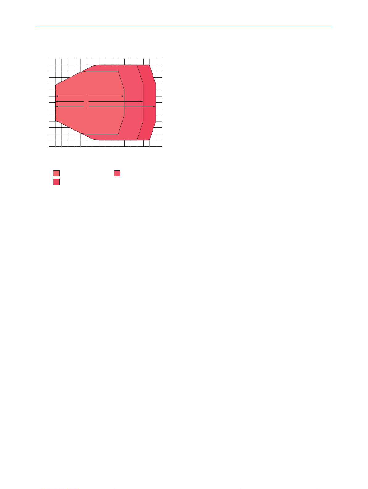
a
b
c
Reading field height in mm
–200
200
–400
400
600
–600
0
400 700 1000 1300 1600 1900 2200
Reading distance in mm
Resolution
a: 0.30mm
c: 0.50mm
b: 0.35mm
12 TECHNICAL DATA
12.6.3 Standard Density: reading performance data, line scanner
Figure 82: CLV690-0xxx (Standard Density): reading field height depending on the reading distance and resolution
100
O PE R AT I NG IN S TR U CT I ON S | CLV69x 8014396/ZMG8/2017-07-04 | SICK
Subject to change without notice
 Loading...