

Page 1

T E C H N I C A L I N F O R M A T I O N
CLV62x, CLV63x and CLV64x with IP69K Protec‐
tive Housing
Bar Code Scanners
Page 2
Described product
CLV62x, CLV63x and CLV64x in IP69K protective housing
Manufacturer
SICK AG
Erwin-Sick-Str. 1
79183 Waldkirch
Germany
Legal information
This work is protected by copyright. Any rights derived from the copyright shall be
reserved for SICK AG. Reproduction of this document or parts of this document is only
permissible within the limits of the legal determination of Copyright Law. Any modifica‐
tion, abridgment or translation of this document is prohibited without the express writ‐
ten permission of SICK AG.
The trademarks stated in this document are the property of their respective owner.
© SICK AG. All rights reserved.
Original document
This document is an original document of SICK AG.
2
T EC H NI C AL IN F OR M AT I ON | CLV62x, CLV63x and CLV64x with IP69K Protective Housing 8021479/0000/2018-03-12 | SICK
Subject to change without notice
Page 3

Contents
CONTENTS
1 About this document........................................................................ 4
1.1 Information on the Technical Information............................................... 4
1.2 Explanation of symbols............................................................................ 4
2 Safety information............................................................................ 6
2.1 Intended use............................................................................................. 6
2.2 Improper use............................................................................................. 6
2.3 Hazard warnings and operational safety................................................. 6
2.3.1 Laser radiation......................................................................... 6
3 Product description........................................................................... 10
3.1 Product ID.................................................................................................. 10
3.1.1 Type label................................................................................. 10
3.2 Design........................................................................................................ 11
3.3 Scope of delivery....................................................................................... 13
3.4 Differences between devices in IP65 standard housing and devices
in IP69K protective housing..................................................................... 14
3.5 Reading fields........................................................................................... 15
4 Transport and storage....................................................................... 18
4.1 Bar code scanners CLV62x, CLV63x and CLV64x with IP69K protec‐
tive housing............................................................................................... 18
5 Mounting............................................................................................. 19
5.1 Overview of mounting procedure............................................................. 19
5.2 Mounting requirements............................................................................ 19
5.3 Mounting options...................................................................................... 19
5.4 Mounting the protective double bushing on the protective housing..... 20
5.4.1 Assembly with use of the Ethernet connection..................... 20
5.4.2 Assembly without use of the Ethernet connection................ 22
6 Electrical installation........................................................................ 24
6.1 Safety......................................................................................................... 24
6.1.1 Notes on electrical installation............................................... 24
6.2 Prerequisites for safe operation of the device in a system.................... 25
6.3 Pin assignment of the connections......................................................... 25
7 Technical data.................................................................................... 27
7.1 Bar code scanner CLV62x in IP69K protective housing......................... 27
7.2 Bar code scanner CLV63x in IP69K protective housing......................... 29
7.3 Bar code scanner CLV64x in IP69K protective housing......................... 31
8 Accessories........................................................................................ 34
8.1 Brackets.................................................................................................... 34
8.2 Cables........................................................................................................ 34
8021479/0000/2018-03-12 | SICK T E C HN I CA L I N FO R MA T IO N | CLV62x, CLV63x and CLV64x with IP69K Protective Housing
Subject to change without notice
3
Page 4
1 ABOUT THIS DOCUMENT
1 About this document
1.1 Information on the Technical Information
This Technical Information supplements the respective operating instructions and
describes mounting and electrical installation of CLV62x, CLV63x and CLV64x bar code
scanners which are equipped with an IP69K protective housing.
The operating instructions for the individual product families can be downloaded online
from the respective product page on the Internet.
Table 1: Operating instructions for the CLV62x, CLV63x and CLV64x bar code scanners
Device Material number
Operating
instructions
German
CLV62x 8011964 8011965 8019585 www.sick.com/
CLV63x 8019587 8019588 8019589 www.sick.com/
CLV64x 8019587 8019588 8019589 www.sick.com/
Material number
Operating
instructions
English
Material number
Operating
instructions
French
Product page
CLV62x
CLV63x
CLV64x
This Technical Information contains the device-specific information on the device,
mounting and electrical connection. See the operating instructions of the respective
product family for more information.
Adherence to all the specified safety notes, warnings and guidelines in this Technical
Information and in the corresponding operating instructions is a prerequisite for work‐
ing safely.
This Technical Information is intended to be used by qualified personnel and electrical
specialists.
NOTE
Carefully read this Technical Information and the operating instructions of the bar code
scanner before carrying out any work with the device.
1.2 Explanation of symbols
Warnings and important information in this document are labeled with symbols. The
warnings are introduced by signal words that indicate the extent of the danger. These
warnings must be observed at all times and care must be taken to avoid accidents, per‐
sonal injury, and material damage.
DANGER
… indicates a situation of imminent danger, which will lead to a fatality or serious
injuries if not prevented.
WARNING
… indicates a potentially dangerous situation, which may lead to a fatality or serious
injuries if not prevented.
CAUTION
… indicates a potentially dangerous situation, which may lead to minor/slight injuries if
not prevented.
4
T EC H NI C AL IN F OR M AT I ON | CLV62x, CLV63x and CLV64x with IP69K Protective Housing 8021479/0000/2018-03-12 | SICK
Subject to change without notice
Page 5

ABOUT THIS DOCUMENT 1
NOTICE
… indicates a potentially harmful situation, which may lead to material damage if not
prevented.
NOTE
… highlights useful tips and recommendations as well as information for efficient and
trouble-free operation.
8021479/0000/2018-03-12 | SICK T E C HN I CA L I N FO R MA T IO N | CLV62x, CLV63x and CLV64x with IP69K Protective Housing
Subject to change without notice
5
Page 6

2 SAFETY INFORMATION
2 Safety information
2.1 Intended use
The device consists of a bar code scanner of the product family CLV62x, CLV63x or
CLV64x in the Ethernet version with a protective housing with enclosure rating IP69K.
The protective housing comprises two parts, the bar code scanner that is permanently
installed in the protective housing at the factory and the supplied protective double
bushing including sealing materials for the two electrical connections.
The device is protected against water from high-pressure or steam cleaners and against
dust subject to use of the corresponding cables and correct mounting. For the specifi‐
cation, see "Technical data", page 27
NOTICE
The following requirements must be met in order to achieve the IP69K enclosure rating:
Use only the connection cables specified by SICK.
•
Seal the two cable outlets at the protective double bushing with the corresponding
•
O-rings.
The O-rings are included in the device scope of delivery and are matched to the outer
diameters of the plug connectors.
The device is an intelligent, opto-electronic SICK ID sensor and is used for automated,
fixed identification and decoding of bar codes on moving or stationary objects. The
device transmits the data content of the decoded bar codes to a higher-level control
(PLC) for coordinating further processing.
SICK AG assumes no liability for losses or damage arising from the use of the product,
either directly or indirectly. This applies in particular to use of the product that does not
conform to its intended purpose and is not described in this documentation.
2.2
Improper use
■
The protective housing of the factory-installed bar code scanner must not be
opened.
■
The device must not be used in explosion-hazardous areas.
■
The device does not constitute a safety-relevant device according to the EC
Machinery Directive (2006/42/EC).
■
Any other use that is not described as intended use is prohibited.
■
Any use of mounting accessories not specifically approved by SICK AG is at your
own risk.
2.3 Hazard warnings and operational safety
To reduce health risks and to avoid dangerous situations, observe the safety notes and
warnings set out in the following chapters of these operating instructions.
2.3.1 Laser radiation
6
T EC H NI C AL IN F OR M AT I ON | CLV62x, CLV63x and CLV64x with IP69K Protective Housing 8021479/0000/2018-03-12 | SICK
The devices work with a red light laser diode in the wavelength 655 nm. They corre‐
spond to laser class 2.
Subject to change without notice
Page 7
1 2
3 3
SAFETY INFORMATION 2
CAUTION
Optical radiation: Laser class 2
The human eye is not at risk when briefly exposed to the radiation for up to 0.25 sec‐
onds. Exposure to the laser beam for longer periods of time may cause damage to the
retina. The laser radiation is harmless to human skin.
■
Do not look into the laser beam intentionally.
■
Never point the laser beam at people's eyes.
■
If it is not possible to avoid looking directly into the laser beam, e.g., during com‐
missioning and maintenance work, suitable eye protection must be worn.
■
Avoid laser beam reflections caused by reflective surfaces. Be particularly careful
during mounting and alignment work.
■
Do not open the housing. Opening the housing may increase the level of risk.
■
Current national regulations regarding laser protection must be observed.
It is not possible to entirely rule out temporary disorienting optical effects, particularly
in conditions of dim lighting. Disorienting optical effects may come in the form of daz‐
zle, flash blindness, afterimages, photosensitive epilepsy, or impairment of color vision,
for example.
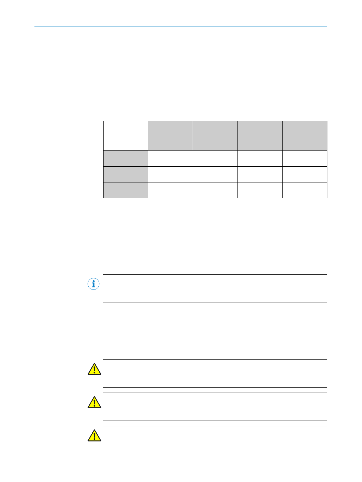
Output of laser radiation at the device
The entire reading window is a laser output aperture.
Figure 1: Reading window and output aperture of laser radiation in IP69K protective housing
Bar code scanners CLV62x, CLV63x and CLV64x with front reading window
1
Bar code scanners CLV63x and CLV64x with oscillating mirror and side reading window
2
Reading window and laser output aperture
3
NOTE
No maintenance is required to ensure compliance with Class 2 laser.
8021479/0000/2018-03-12 | SICK T E C HN I CA L I N FO R MA T IO N | CLV62x, CLV63x and CLV64x with IP69K Protective Housing
Subject to change without notice
Warning symbol on the device
The laser warning label is lasered onto the protective housing. The type label is
attached on the housing side of the connections.
In addition to other information, the type label also contains the laser output data. This
data consists of: Laser output power (maximum/average), wavelength or wavelength
range, and pulse time duration, see "Type label", page 10.
7
Page 8
4
1
3
4
3
2
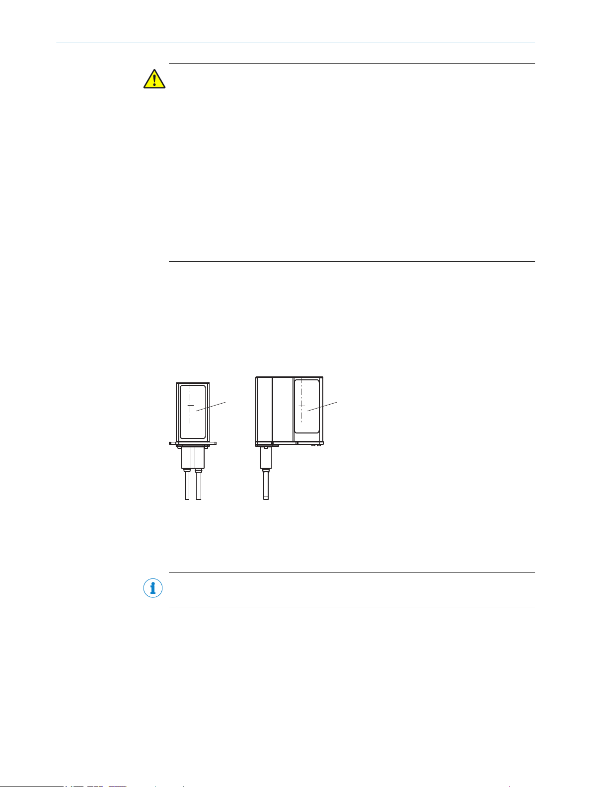
2 SAFETY INFORMATION
Figure 2: Position of type label and laser warning label on the IP69K protective housing
1
2
3
4
Bar code scanners CLV62x, CLV63x and CLV64x with front reading window
Bar code scanners CLV63x and CLV64x with oscillating mirror and side reading window
Position of the type label
Position of the laser warning label
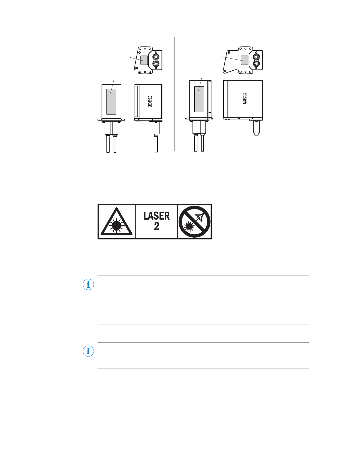
Figure 3: Inhalt des Laserwarnschildes am Gerät
What the laser warning label means: Laser radiation – Never look into the light beam –
Laser class 2
NOTE
Additional laser warning label
If the laser warning label applied to the protective housing is concealed when the
device is installed into a machine or paneling, the laser beam output aperture must be
suitably labeled. For this purpose, an additional warning label of the same type must be
applied next to the output aperture.
Controlling the laser diode
NOTE
The CLV62x, CLV63x and CLV64x bar code scanners in IP69K protective housing do not
have an externally visible visual indicator (LED) for laser diode activity.
When operating properly, the device only switches the laser diode on if there is an
object in the reading area, or if a reading is required (cyclic reading operation).
A laser timeout can switch off the laser diode automatically in this type of object trigger
control if the pulse has stopped for too long (e.g. the conveyor system has stopped). In
this case, the current internal reading interval of the device remains open.
Irrespective of the selected configuration type, the laser timeout can be set as follows:
8
T EC H NI C AL IN F OR M AT I ON | CLV62x, CLV63x and CLV64x with IP69K Protective Housing 8021479/0000/2018-03-12 | SICK
Subject to change without notice
Page 9

SAFETY INFORMATION 2
Using the SOPAS ET configuration software, on the Illumination Control device page
•
During GSD configuration with the “10_Object Trigger Ctrl” module (PROFINET/
•
PROFIBUS)
At the default setting, laser timeout is deactivated.
The laser diode is permanently or repeatedly switched on in the following device sta‐
tuses:
■
In the “Percentage Evaluation” and “Auto Setup” operating modes (only used tem‐
porarily for configuration or diagnosis)
■
In reading operation in the PSDI types “Auto pulse” (adjustable duty cycle) or
“free.”
If timeout is activated, it will have no effect here.
8021479/0000/2018-03-12 | SICK T E C HN I CA L I N FO R MA T IO N | CLV62x, CLV63x and CLV64x with IP69K Protective Housing
Subject to change without notice
9
Page 10
D-79276 Reute
Made in Germany
1
2
4
6
3
7
8
ß
9
à
5
CLV631-0831S01
P/N: 1062070
S/N: 1249 0001
DC 18...30V 8.5W
Imax=800mA
Pmax=7.0mW
P<1.0mW average
λ=655nm
Pulse duration <80μS
MAC 00:00:00:00:00:00
Manufactured: April 2017
3 PRODUCT DESCRIPTION
3 Product description
3.1 Product ID
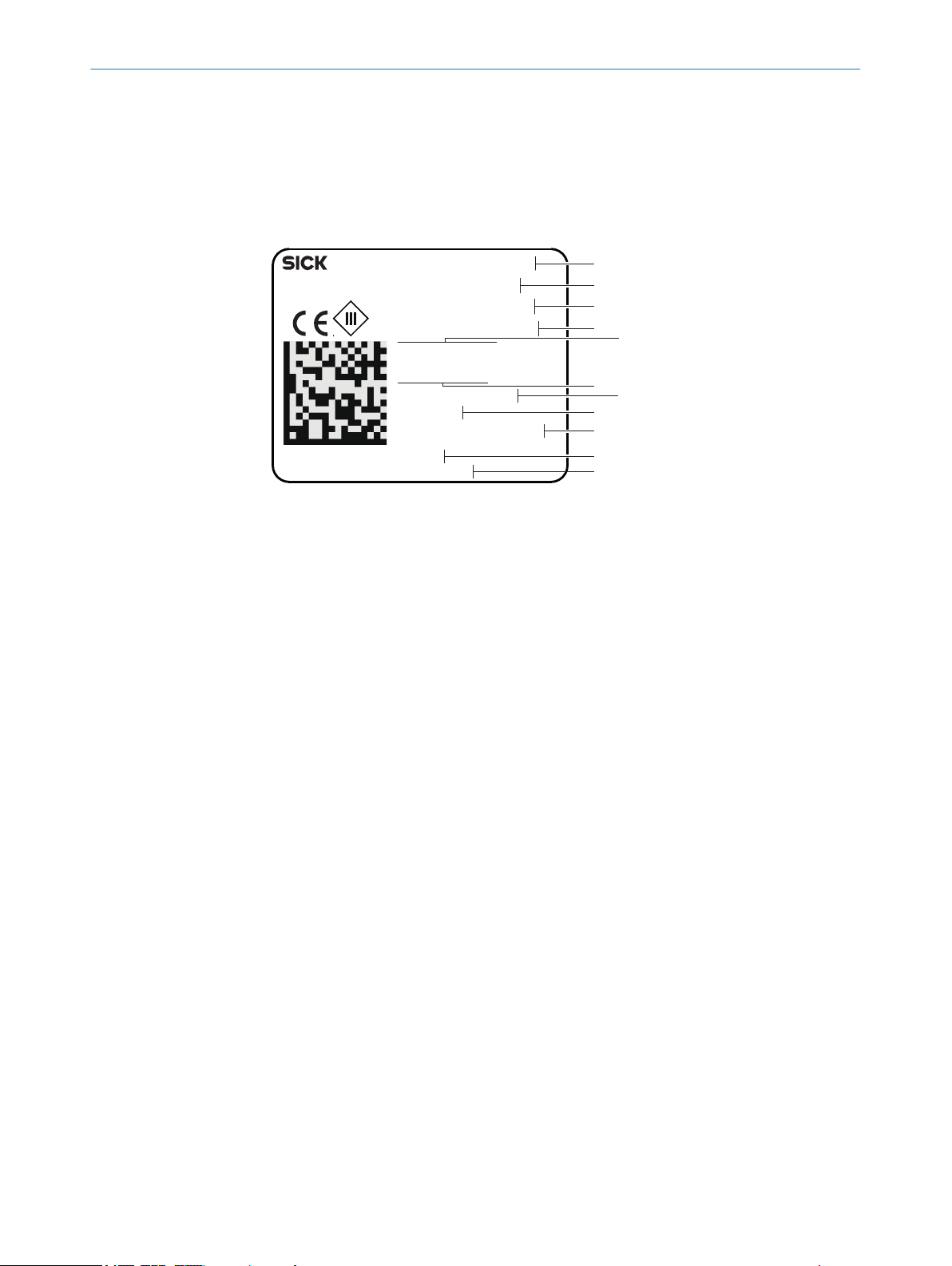
3.1.1 Type label
The type label is attached on the housing side with the electrical connections.
Figure 4: Type label on IP69K protective housing (example)
Type designation
1
Part number
2
Serial number
3
Supply voltage and power consumption
4
Maximum current consumption
5
Maximum laser output
6
Average laser output
7
Laser wavelength
8
Laser pulse duration
9
MAC address
ß
Date of manufacture
à
10
T EC H NI C AL IN F OR M AT I ON | CLV62x, CLV63x and CLV64x with IP69K Protective Housing 8021479/0000/2018-03-12 | SICK
Subject to change without notice
Page 11
3.2 Design
50°
70 (2.76)
1
2
30
(1.18)
52.5
(2.07)
71.5 (2.81)
30.4
(1.20)
84 (3.31)
59 (2.32)
12.5
(0.49)
24
(0.94)
3
85 (3.35)
110 (4.33)
44
(1.73)
24
(0.94)
4
4
PRODUCT DESCRIPTION 3
CLV62x in IP69K protective housing, front reading window
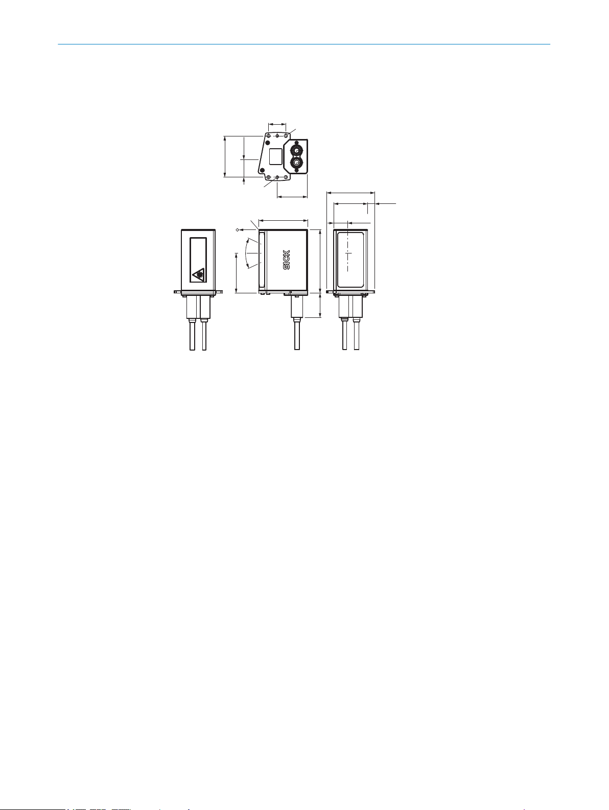
Figure 5: CLV62x: design and device dimensions of the IP69K protective housing with front read‐
ing window (dimensions in mm or inch)
Fixing holes, dia. 5.5 mm (4 x)
1
“Ethernet” connection, female connector, M12, 4-pin, D-coded
2
“Power/Serial Data/CAN/I/O” connection, male connector, M12, 17-pin, A-coded
3
Threaded hole, M5 (2 x)
4
Reference point for reading distance (housing edge – object)
5
Light emission position (central position of the deflected laser beam)
6
Protective double bushing for the electrical connections
7
8021479/0000/2018-03-12 | SICK T E C HN I CA L I N FO R MA T IO N | CLV62x, CLV63x and CLV64x with IP69K Protective Housing
Subject to change without notice
11
Page 12

50°
70 (2.76)
1
2
30
(1.18)
52.5
(2.07)
71.5 (2.81)
30.4
(1.20)
84 (3.31)
59 (2.32)
12.5
(0.49)
24
(0.94)
3
85 (3.35)
110 (4.33)
44
(1.73)
24
(0.94)
4
4
3 PRODUCT DESCRIPTION
CLV63x or CLV64x in IP69K protective housing, front reading window
Figure 6: CLV63x / CLV64x: design and device dimensions of the IP69K protective housing with
front reading window (dimensions in mm or inch)
Fixing holes, dia. 5.5 mm (4 x)
1
“Ethernet” connection, female connector, M12, 4-pin, D-coded
2
“Power/Serial Data/CAN/I/O” connection, male connector, M12, 17-pin, A-coded
3
Threaded hole, M5 (2 x)
4
Reference point for reading distance (housing edge – object)
5
Light emission position (central position of the deflected laser beam)
6
Protective double bushing for the electrical connections
7
12
T EC H NI C AL IN F OR M AT I ON | CLV62x, CLV63x and CLV64x with IP69K Protective Housing 8021479/0000/2018-03-12 | SICK
Subject to change without notice
Page 13

88.5 (3.48)
29.2
(1.15)
52.5
(2.07)
30
(1.18)
5
(0.20)
20°
20°
1
05°
71.5 (2.81)
30.4
(1.20)
121 (4.76)
120 (4.72)
44
(1.73)
70 (2.76)
50°
84 (3.31)
69 (2.72)
12.5
(0.49)
71 (2.80)
43
(1.69)
88.5 (3.48)
95 (3.74)
20
(0.79)
1
2
3
4
4
PRODUCT DESCRIPTION 3
CLV63x or CLV64x with oscillating mirror in the IP69K protective housing, side reading
window
3.3 Scope of delivery
Figure 7: CLV63x / CLV64x with oscillating mirror: design and device dimensions of the IP69K
protective housing, side reading window (dimensions in mm or inch)
Fixing holes, dia. 5.5 mm (4 x)
1
“Ethernet” connection, female connector, M12, 4-pin, D-coded
2
“Power/Serial Data/CAN/I/O” connection, male connector, M12, 17-pin, A-coded
3
Threaded hole, M5 (2 x)
4
Reference point for reading distance (housing edge – object)
5
Light emission position (central position of the deflected laser beam and oscillating mirror
6
in central position)
Protective double bushing for the electrical connections
7
The scope of delivery of the device includes the following components:
Table 2: Scope of delivery
Item Component Description
1 Bar code scanner CLV62x, CLV63x or
CLV64x in the ordered version, in the
screwed IP69K protective housing
Both M12 connections fitted with protec‐
tive plug or cap.
8021479/0000/2018-03-12 | SICK T E C HN I CA L I N FO R MA T IO N | CLV62x, CLV63x and CLV64x with IP69K Protective Housing
Subject to change without notice
13
Page 14

3 PRODUCT DESCRIPTION
Item Component Description
1 Protective double bushing for the two
2 O-ring
2 O-ring
1 Dummy plug Seals the free bushing of the protective
electrical connections in the terminal
compartment
Inside diameter x cord thickness:
11.0 mm x 4.0 mm
Inside diameter x cord thickness:
13.5 mm x 3.0 mm
Seals the connections and the two cable
outlets to the outside. Use of both bush‐
ings or only one bushing with dummy plug
for the free bushing.
Protective double bushing equipped with:
Recessed flat seal on the side to the
•
protective housing
One internal groove in each case at
•
the end of the bushings (cable out‐
let) to accommodate an O-ring for
sealing
Two captive mounting screws for
•
securing on the protective housing
Seals the plug connector for the “Ether‐
net” connection towards the protective
double bushing.
One O-ring serves as a spare part.
Seals the plug connector for the “Power/
Serial Data/CAN/I/O” connection towards
the protective double bushing.
One O-ring serves as a spare part.
double bushing if the Ethernet connection
is not used. Matching O-ring: 11.0 mm x
4.0 mm.
3.4 Differences between devices in IP65 standard housing and devices in IP69K pro‐
tective housing
Table 3: Differences between devices in IP65 standard housing and devices in IP69K protective
housing
Feature Devices in IP65 standard housing Devices in IP69K protective housing
Housing variant Front reading window: CLV62x,
CLV63x and CLV64x
Side reading window and oscillating
mirror: CLV63x and CLV64x
Side reading window: CLV62x,
CLV63x and CLV64x
Housing material Die-cast aluminum Stainless steel
Housing color Blue, painted Unpainted
Enclosure rating IP65 IP69K
Reading window Glass or plastic Plastic
Reading fields For glass: 100%
For plastic: depth of field reduced by
10%
Laser warning
label
Status displays CLV62x: 6 LEDs
Operating but‐
tons
Stuck on Lasered on
CLV63x and CLV64x: 6 LEDs and bar
graph display
CLV62x: None
CLV63x and CLV64x: 2
Front reading window: CLV62x,
CLV63x and CLV64x
Side reading window and oscillating
mirror: CLV63x and CLV64x
––
Depth of field reduced by 10%
Distance to device smaller
Omitted
Omitted
14
T EC H NI C AL IN F OR M AT I ON | CLV62x, CLV63x and CLV64x with IP69K Protective Housing 8021479/0000/2018-03-12 | SICK
Subject to change without notice
Page 15

Feature Devices in IP65 standard housing Devices in IP69K protective housing
Optional plug-in
memory card for
parameter
cloning
Mounting 2 x 2 blind tapped hole M5, 5 mm
SOPAS ET Shows the reading field of the
3.5 Reading fields
The reading fields of the devices in IP69K protective housing differ from the devices in
IP65 standard housing with respect to the position of the housing edge and the depth
of field.
■
■
PRODUCT DESCRIPTION 3
CLV62x: None
CLV63x and CLV64x: 1
deep
devices in the standard housing
Position: The distance between the reading field and housing edge is smaller than
on the standard devices in the case of devices in IP69K protective housing. The
reason for this is the longer light path in the IP69K protective housing.
Depth of field: On devices in the IP69K protective housing, the depth of field is
reduced by approx. 10% (reduction of reading fields on both sides by 5% in each
case for all module widths). This is due to the reading window made of plastic.
Omitted
4 x holes 5.5 mm
2 x threaded holes M5
Shows the reading field of the
devices in the standard housing
On devices in IP69K protective housing, the distance between the reading window and
housing edge is reduced as follows compared with the reading window (glass) of a
device in the standard housing:
■
Bar code scanner with front reading window: 10.7 mm
■
Bar code scanner with oscillating mirror and side reading window: 11.16 mm
Example: reading fields of the CLV631 with front reading window
The following table shows the reading fields of two comparable bar code scanners with
front reading window by way of example.
8021479/0000/2018-03-12 | SICK T E C HN I CA L I N FO R MA T IO N | CLV62x, CLV63x and CLV64x with IP69K Protective Housing
Subject to change without notice
15
Page 16

500
(19.69)
300
(11.81)
400
(15.75)
200
(7.87)
100
(3.94)
0
Reading distance in mm (inch) 2
Resolution 3
a: 0.25 mm (9.8 mil)
c: 0.50 mm (19.7 mil)
b: 0.35 mm (13.8 mil)
–100
(–3.94)
–200
(–7.87)
100
(3.94)
200
(7.87)
0
Reading field height in mm (inch) 1
a
b
c
0
0
a
b
c
–100
(–3.94)
–200
(–7.87)
100
(3.94)
200
(7.87)
Reading field height in mm (inch) 1
Reading distance in mm (inch) 2
500
(19.69)
300
(11.81)
400
(15.75)
200
(7.87)
100
(3.94)
Resolution 3
a: 0.25 mm (9.8 mil)
c: 0.50 mm (19.7 mil)
b: 0.35 mm (13.8 mil)
3 PRODUCT DESCRIPTION
Table 4: CLV631 reading fields with front reading window
CLV631 in standard housing CLV631 in IP69K protective housing
Figure 8: Reading field diagram of CLV631-0120, reading win‐
dow at front
Reading field height in mm (inch)
1
Reading distance in mm (inch)
2
Resolution
3
Figure 9: Reading field diagram of CLV631-0831S01, front
reading window
Reading field height in mm (inch)
1
Reading distance in mm (inch)
2
Resolution
3
Example: reading fields of CLV631 with oscillating mirror and side reading window
The following table shows the reading fields of two comparable bar code scanners with
oscillating mirror and side reading window by way of example.
16
T EC H NI C AL IN F OR M AT I ON | CLV62x, CLV63x and CLV64x with IP69K Protective Housing 8021479/0000/2018-03-12 | SICK
Subject to change without notice
Page 17

500
(19.69)
300
(11.81)
400
(15.75)
200
(7.87)
100
(3.94)
0
Reading distance in mm (inch) 2
Resolution 3
a: 0.25 mm (9.8 mil)
c: 0.50 mm (19.7 mil)
b: 0.35 mm (13.8 mil)
–100
(–3.94)
–200
(–7.87)
100
(3.94)
200
(7.87)
0
Reading field height in mm (inch) 1
a
b
c
a
b
c
–100
(–3.94)
–200
(–7.87)
100
(3.94)
200
(7.87)
0
Reading field height in mm (inch) 1
500
(19.69)
300
(11.81)
400
(15.75)
200
(7.87)
100
(3.94)
0
Reading distance in mm (inch) 2
Resolution 3
a: 0.25 mm (9.8 mil)
c: 0.50 mm (19.7 mil)
b: 0.35 mm (13.8 mil)
PRODUCT DESCRIPTION 3
Table 5: Reading fields of CLV631 with oscillating mirror and side reading window
CLV631 in standard housing CLV631 in IP69K protective housing
Figure 10: Reading field diagram of CLV631-6120, oscillating
mirror and side reading window
Reading field height in mm (inch)
1
Reading distance in mm (inch)
2
Resolution
3
Figure 11: Reading field diagram of CLV631-6831S01, oscil‐
lating mirror and side reading window
Reading field height in mm (inch)
1
Reading distance in mm (inch)
2
Resolution
3
Display of reading field diagrams in SOPAS ET
The SOPAS ET configuration software displays the reading field diagrams of the bar
code scanners in standard housing (reading window made of glass). The diagrams
therefore do not provide a true representation of the restricted and displaced reading
areas of the bar code scanners in IP69K protective housing (reading window made of
plastic).
NOTE
As a simplified rule: the depth of field is reduced by approx. 10% for devices with a plas‐
tic reading window.
8021479/0000/2018-03-12 | SICK T E C HN I CA L I N FO R MA T IO N | CLV62x, CLV63x and CLV64x with IP69K Protective Housing
Subject to change without notice
17
Page 18

4 TRANSPORT AND STORAGE
4 Transport and storage
4.1 Bar code scanners CLV62x, CLV63x and CLV64x with IP69K protective housing
For transport and storage of the devices, see the operating instructions of the respec‐
tive bar code scanner.
During transport and storage, additionally make sure that the connections on the pro‐
tective housing are sealed with the corresponding protective covers.
18
T EC H NI C AL IN F OR M AT I ON | CLV62x, CLV63x and CLV64x with IP69K Protective Housing 8021479/0000/2018-03-12 | SICK
Subject to change without notice
Page 19

5 Mounting
5.1 Overview of mounting procedure
Choose and prepare the mounting location.
•
Connect the connection cables at the protective housing via the protective double
•
bushing, seal the cable outlets and mount the protective double bushing on the
protective housing.
Mount the device on a bracket.
•
Align the device towards objects with bar code.
•
Adjust the device.
•
For mounting location, mounting, alignment and adjustment, see the operating instruc‐
tions of the respective bar code scanner.
MOUNTING 5
5.2
Mounting requirements
The following tools and auxiliary equipment are required for mounting:
■
Lubricant such as Vaseline
Please observe the following:
■
Pay attention to the space requirements of the device. See type-specific dimen‐
sional drawing and reading field diagram.
■
Observe the technical data of the device.
■
To prevent condensation, avoid exposing the device to rapid changes in tempera‐
ture.
■
Protect the device from direct sunlight.
■
Mount the device so that it is not exposed to shock and vibration.
■
Preferably route the connection cables downwards away from the device.
5.3 Mounting options
You can mount the device as follows:
■
Mount the device on an optional SICK bracket. The device is mounted on the
bracket by means of the 2 M5 threaded holes. For the optional SICK brackets, see
www.sick.com.
■
Mount the device on a user-supplied bracket. You can mount the device on the
bracket as follows:
■
■
Dimensional drawings see "Design", page 11.
With at least two M5 screws (in pairs) using two of the four 5.5 mm holes
Using the 2 M5 blind tapped holes
For an exact description of the device mounting procedure, see the operating instruc‐
tions of the respective bar code scanner.
Requirements for a user-supplied bracket
The brackets must meet the following requirements:
The bracket must be designed for the weight of the device including connection
•
cables, see "Technical data", page 27
The bracket must be able to support the device free of vibrations and oscillations.
•
It must be possible to adjust the bracket in x- and y-axes.
•
The bracket must have the required holes for mounting the device on the bracket.
•
8021479/0000/2018-03-12 | SICK T E C HN I CA L I N FO R MA T IO N | CLV62x, CLV63x and CLV64x with IP69K Protective Housing
Subject to change without notice
19
Page 20

1
2
3
4
5
6
7
8
9
ß
5 MOUNTING
5.4 Mounting the protective double bushing on the protective housing
During assembly, the connection cables are routed through the supplied protective dou‐
ble bushing and connected to the device in the protective housing.
If the Ethernet interface is not used, you must close off the free feedthrough in the pro‐
tective double bushing with the supplied dummy plug.
NOTE
Use connection cables with a sufficient length.
NOTICE
The power supply must be disconnected when attaching and detaching electrical con‐
nections.
NOTICE
Do not install O-rings using sharp or pointed tools. The O-rings seal the protective dou‐
ble bushing towards the outside and therefore guarantee the enclosure rating.
5.4.1 Assembly with use of the Ethernet connection
Noting the MAC address
NOTE
The MAC address for the Ethernet interface is located on the type label, see "Type
label", page 10. The address is partially or completely covered when the device is
mounted on a bracket.
Make a note of the MAC address and the name of the reading station.
Mounting the protective double bushing on the protective housing
Assembly is described on the basis of the protective housing for bar code scanner with
front reading window. Assembly of protective housings for bar code scanners with oscil‐
lating mirror and side reading window takes place analogously.
Component overview
20
Figure 12: Assembly of IP69K protective housing, with use of the Ethernet connection
1
T EC H NI C AL IN F OR M AT I ON | CLV62x, CLV63x and CLV64x with IP69K Protective Housing 8021479/0000/2018-03-12 | SICK
2
3
4
Connection cable for “Ethernet” connection
Plug connector of connection cable for “Ethernet” connection
O-ring 11.0 mm x 4.0 mm
Protective double bushing
Subject to change without notice
Page 21

5
“Ethernet” connection, female connector, M12, 4-pin, D-coded
5
Protective housing, here for bar code scanners with front reading window
6
“Power/Serial Data/CAN/I/O” connection, male connector, M12, 17-pin, A-coded
7
O-ring 13.5 mm x 3.0 mm
8
Plug connector of connection cable for “Power/Serial Data/CAN/I/O” connection
9
Connection cable for “Power/Serial data/CAN/I/O” connection
ß
MOUNTING
When delivered, both connections on the protective housing are equipped with a protec‐
tive cover.
Auxiliary equipment required
Lubricant such as Vaseline
•
1. Position the device at the operating location.
2. Unscrew the protective plug from the 4-pin female connector. Turn the protective
plug counterclockwise for this purpose.
3. Unscrew the protective cap from the 17-pin male connector. Turn the protective
cap counterclockwise for this purpose.
Figure 13: Assembly of IP69K protective housing, with use of the Ethernet connection – Step 1
4. Guide O-ring 13.5 mm x 3.0 mm over the plug connector of the “Power/Serial
data/CAN/I/O” connection cable.
5. Guide O-ring 11.0 mm x 4.0 mm over the plug connector of the “Ethernet” connec‐
tion cable.
Figure 14: Assembly of IP69K protective housing, with use of the Ethernet connection – Step 2
6. Guide plug connector of the “Ethernet” connection cable through the protective
double bushing.
7. Connect “Ethernet” connection cable to the M12 female connector of the protec‐
tive housing.
8. Tighten coupling nut of the connected connection cable.
9. Guide the plug connector for the “Power/Serial Data/CAN/I/O” connection cable
through the protective double bushing.
10. Connect the “Power/Serial Data/CAN/I/O” connection cable at the M12 male con‐
nector of the protective housing.
11. Tighten coupling nut of the connected connection cable.
12. Position O-rings in the provided grooves of the protective double bushing.
8021479/0000/2018-03-12 | SICK T E C HN I CA L I N FO R MA T IO N | CLV62x, CLV63x and CLV64x with IP69K Protective Housing
Subject to change without notice
21
Page 22

2
3
4
5
6
1
7
8
9
5 MOUNTING
Figure 15: Assembly of IP69K protective housing, with use of the Ethernet connection – Step 3
13. Apply a small amount of a lubricant such as Vaseline as shown in the figure. This
makes it easier to slide the protective double bushing over the plug connectors.
14. Carefully push the protective double bushing over the plug connectors.
15. Make sure that the O-rings are correctly positioned in the grooves of the protective
double bushing.
Figure 16: Assembly of IP69K protective housing, with use of the Ethernet connection – Step 4
16. Mount the protective double bushing on the protective housing using the two
screws provided.
5.4.2 Assembly without use of the Ethernet connection
Mounting the protective double bushing on the protective housing
Assembly is described on the basis of the protective housing for bar code scanner with
front reading window. Assembly of protective housings for bar code scanners with oscil‐
lating mirror and side reading window takes place analogously.
Component overview
22
Figure 17: Assembly of IP69K protective housing, without use of the Ethernet connection
Dummy plug for “Ethernet” feedthrough
1
Subject to change without notice
T EC H NI C AL IN F OR M AT I ON | CLV62x, CLV63x and CLV64x with IP69K Protective Housing 8021479/0000/2018-03-12 | SICK
Page 23

5
O-ring 11.0 mm x 4.0 mm
2
Protective double bushing
3
Protective plug for unused Ethernet connection, female connector, Dose, M12, 4-pin, D-
4
coded
Protective housing, here for bar code scanners with front reading window
5
“Power/Serial Data/CAN/I/O” connection. male connector, M12, 17-pin, A-coded
6
O-ring 13.5 mm x 3.0 mm
7
Plug connector of connection cable
8
Connection cable for “Power/Serial data/CAN/I/O” connection
9
MOUNTING
When delivered, both connections on the protective housing are equipped with a protec‐
tive cover.
Auxiliary equipment required
Lubricant such as Vaseline
•
1. Make sure that the protective plug of the Ethernet connection is securely tight‐
ened.
2. Guide connection cable through the protective double bushing. Seal the lower
feedthrough with the O-ring. Connect the connection cable at the protective hous‐
ing, see "Assembly with use of the Ethernet connection", page 20
3. Position O-ring 11.0 mm x 4.0 mm in the groove of the upper feedthrough of the
protective double bushing.
4. Close off the upper feedthrough of the protective double bushing with the supplied
dummy plug.
Figure 18: Assembly of IP69K protective housing, without use of the Ethernet connection –
dummy plug
5. Apply lubricant. Push protective double bushing over the plug connector and the
Ethernet connection. Mount the protective double bushing on the protective hous‐
ing, see "Assembly with use of the Ethernet connection", page 20
Figure 19: Assembly of IP69K protective housing, without use of the Ethernet connection
8021479/0000/2018-03-12 | SICK T E C HN I CA L I N FO R MA T IO N | CLV62x, CLV63x and CLV64x with IP69K Protective Housing
Subject to change without notice
23
Page 24

6 ELECTRICAL INSTALLATION
6 Electrical installation
6.1 Safety
6.1.1 Notes on electrical installation
NOTICE
Equipment damage due to incorrect supply voltage!
An incorrect supply voltage may result in damage to the equipment.
■
Only operate the device using a protected low voltage and safe electrical insulation
as per protection class III.
NOTICE
Equipment damage or unpredictable operation due to working with live parts.
Working with live parts may result in unpredictable operation.
■
Only carry out wiring work when the power is off.
■
Only connect and disconnect electrical connections when the power is off.
■
Electrical installation must only be performed by electrically qualified personnel.
■
Standard safety requirements must be observed when working on electrical sys‐
tems.
■
Only switch on the supply voltage for the device when the connection tasks have
been completed and the wiring has been thoroughly checked.
■
When using extension cables with open ends, ensure that bare wire ends do not
come into contact with each other (risk of short-circuit when supply voltage is
switched on!). Wires must be appropriately insulated from each other.
■
Wire cross-sections in the supply cable from the user’s power system must be
selected in accordance with the applicable standards. When this is being done in
Germany, observe the following standards: DIN VDE 0100 (Part 430) and DIN VDE
0298 (Part 4) and/or DIN VDE 0891 (Part 1).
■
Circuits connected to the device must be designed as SELV circuits (SELV = Safety
Extra Low Voltage).
■
Protect the device with a separate fuse of max. 2 A at the start of the supply cir‐
cuit.
24
NOTE
Layout of data cables
■
Use screened data cables with twisted-pair wires.
■
Implement the screening design correctly and completely.
■
To avoid interference, e.g. from switching power supplies, motors, clocked drives,
and contactors, always use cables and layouts that are suitable for EMC.
■
Do not lay cables over long distances in parallel with power supply cables and
motor cables in cable channels.
The specified enclosure rating IP69K is achieved for the device only under the following
conditions:
■
The protective housing is assembled as described in these instructions.
■
The Ethernet connection of the device is used: see "Assembly with use of the
Ethernet connection", page 20
■
The Ethernet connection of the device is not used: see "Assembly without use
of the Ethernet connection", page 22
■
Use of the specified cables, see "Cables", page 34
T EC H NI C AL IN F OR M AT I ON | CLV62x, CLV63x and CLV64x with IP69K Protective Housing 8021479/0000/2018-03-12 | SICK
Subject to change without notice
Page 25

1
43
2
3
1
7
2
6
5
4
8
13
14
17
15
9
10
12
16
11
ELECTRICAL INSTALLATION 6
6.2 Prerequisites for safe operation of the device in a system
See operating instructions of the bar code scanner.
6.3 Pin assignment of the connections
Figure 20: Female connector, M12, 4-pin, D-coded
Table 6: Ethernet version: Pin assignment on the 4-pin M12 female connector
Pin Signal Function
1 TD+ Sender+
2 RD+ Receiver+
3 TD– Sender–
4 RD– Receiver–
– – Shield
Figure 21: Male connector, M12, 17-pin, A-coded
Table 7: Ethernet version: Pin assignment on 17-pin M12 male connector
Pin Signal Function
1 GND Ground
2 CLV62x: DC 10 V ... 30 V
Supply voltage
CLV63x, CLV64x:
DC 18 V ... 30 V
3 CAN L CAN bus (IN/OUT)
4 CAN H CAN bus (IN/OUT)
5 TD+ (RS-422/485) Host interface (sender+)
6 TD– (RS-422/485);
Host interface (sender-)
TxD (RS-232)
7 TxD (AUX) AUX interface (sender)
8 RxD (AUX) AUX interface (receiver)
9 SensGND Switching input ground
10 Sensor 1 Digital switching input (external reading cycle)
11 RD+ (RS-422/485) Host interface (receiver+)
12 RD– (RS-422/485);
Host interface (receiver–)
RxD (RS-232)
13 Result 1 Digital switching output, function can be set
14 Result 2 Digital switching output, function can be set
8021479/0000/2018-03-12 | SICK T E C HN I CA L I N FO R MA T IO N | CLV62x, CLV63x and CLV64x with IP69K Protective Housing
Subject to change without notice
15 Sensor 2 Digital switching input (external reading cycle)
16 – –
25
Page 26

6 ELECTRICAL INSTALLATION
Pin Signal Function
17 – –
26
T EC H NI C AL IN F OR M AT I ON | CLV62x, CLV63x and CLV64x with IP69K Protective Housing 8021479/0000/2018-03-12 | SICK
Subject to change without notice
Page 27

TECHNICAL DATA 7
7 Technical data
7.1 Bar code scanner CLV62x in IP69K protective housing
NOTE
The relevant online data sheet for your product including technical data and dimen‐
sions can be downloaded from the Internet: www.sick.com/CLV62x
Optics
CLV620
Working range Mid range
Scanning method Line or grid scanner 1), for identifier see type code in operating instructions
Reading window orientation Front, for identifier see type code in operating instructions
Aperture angle ≤ 50°
Scan/decoder frequency 400 Hz … 1,200 Hz
Resolution 0.2 mm ... 1.0 mm
Focus Fixed focus
Light source Laser diode, visible red light (λ = 655 nm)
MTBF (laser diode) 40,000 h at 25 °C
Laser class Class 2 in accordance with EN/IEC 60825-1:2014 (identical laser class to EN/IEC
60825-1:2007). Complies with 21 CFR 1040.10 except for tolerances according to Laser
Notice no. 50 of June 24, 2007 and its following versions.
Laser power (maximum/aver‐
age)
Laser pulse duration < 300 μs
1)
Grid height approx. 15 mm at a reading distance of 200 mm
1.5 mW / < 1.0 mW
Performance
CLV620
Bar code types Code 39, Code 128, Code 93, Codabar, GS1-128 / EAN 128, UPC / GTIN / EAN, 2/5 Inter‐
leaved, Pharmacode, GS1 DataBar, Telepen, MSI/Plessey
Print ratio 2:1 ... 3:1
No. of codes per scan 1 ... 20 (standard decoder)
1 ... 6 (SMART620)
No. of codes per reading
interval
1)
No. of characters per code/
reading interval
1 ... 50 (auto-discriminating)
Max. 50 characters / max. 5,000 characters across all bar codes per reading interval, 500
characters for multiplexer function (CAN)
Number of multiple readings 1 ... 99
1)
Reading interval: The time window generated internally by the reading cycle for code detection and evaluation
Interfaces
CLV620
Serial (RS-232,
RS-422/-485)
Ethernet Function: Host, AUX
Function: Host, AUX
Data transmission rate: 2.4 kBd ... 115.2 kBd, AUX: 57.6 kBd (RS-232)
Data transmission rate: 10/100 Mbit/s, half/full duplex
Protocol: TCP/IP, EtherNet/IP, PROFINET Single Port
8021479/0000/2018-03-12 | SICK T E C HN I CA L I N FO R MA T IO N | CLV62x, CLV63x and CLV64x with IP69K Protective Housing
Subject to change without notice
27
Page 28

7 TECHNICAL DATA
CLV620
CAN Function: SICK CAN sensor network (master/slave, multiplexer/server)
Data transmission rate: 20 kbit/s ... 1 Mbit/s
Protocol: CSN (SICK CAN sensor network), CANopen
PROFINET PROFINET Dual Port optional over external fieldbus module CDF600-2
EtherCAT
PROFIBUS Optional via external fieldbus module CDF600-2
DeviceNet Optional over external connection module CDM420 + CMF fieldbus module
Digital switching inputs 2 (“Sensor 1”, “Sensor 2”), 2 additional inputs via CMC600 parameter cloning module in the
Digital switching outputs 2 (“Result 1”, “Result 2”), 2 additional outputs via CMC600 parameter cloning module in the
Reading pulse Pulse sources for start: “Sensor 1” and/or “Sensor 2” switching inputs; command (data inter‐
Optical indicators Not accessible
Acoustic indicator None
Configuration SOPAS ET configuration software, profile programming with bar codes, command language,
®
Optional via external fieldbus module CDF600
CDB650 or CDM420 connection module
Opto-decoupled, Vin = max. 32 V, reverse polarity protected, can be wired via PNP output,
adjustable debouncing 0 ms ... 10,000 ms
CDB650 or CDM420 connection module
PNP, I
= max. 100 mA, short-circuit protected, pulse duration adjustable (static, 10 ms ...
out
10,000 ms)
face), auto pulse, CAN
Pulse sources for stop: reading cycle source, “Sensor 1”, “Sensor 2”, command, timer, condi‐
tion (e.g. Good Read)
GSD configuration
Mechanics/electronics
CLV620
Electrical connection Ethernet version: 2 x round connections (1 x male connector, M12, 17-pin, A-coded, 1 x
female connector, M12, 4-pin, D-coded)
Supply voltage 10 V DC ... 30 V DC, LPS or NEC Class 2, reverse polarity protected
Power consumption Max. 4.5 W with loaded switching outputs
Housing Stainless steel
Housing color Unpainted
Reading window material Plastic
Dimensions (L x W x H)
Weight
2)
Safety EN 60950-1
Electrical protection class III (EN 61140)
Enclosure rating IP69K (DIN 40050, Part 9)
1)
See also see figure 5, page 11
2)
Without connecting cables
1)
85 mm x 84 mm x 154 mm
854 g, with double protective bushing
Test conditions:
Water spray quantity: 14 ... 16 l/min
•
Water pressure/temperature: 10,000 KPa (100 bar) / 80 °C
•
Fan nozzle distance: 100 mm ... 150 mm
•
Spray angle: 0°, 30° , 60°, 90°
•
Cycle: 30 s for each position
•
Rotational speed of test specimen: 5 rpm
•
28
T EC H NI C AL IN F OR M AT I ON | CLV62x, CLV63x and CLV64x with IP69K Protective Housing 8021479/0000/2018-03-12 | SICK
Subject to change without notice
Page 29

Ambient data
CLV620
EMC test Radiated emission: in accordance with EN 61000-6-3 (2007-01)
Immunity: in accordance with EN 61000-6-2 (2005-08)
Vibration resistance EN 60068-2-6: 2008-02
Shock resistance EN 60068-2-27: 2009-05
Ambient operating tempera‐
0 °C ... +40 °C
ture
Storage temperature –20 °C ... +70 °C
Permissible relative humidity 0% ... 90%, non-condensing
Ambient light immunity 2,000 lx, on bar code
Bar code print contrast (PCS) ≥ 60%
7.2 Bar code scanner CLV63x in IP69K protective housing
NOTE
The relevant online data sheet for your product including technical data and dimen‐
sions can be downloaded from the Internet: www.sick.com/CLV63x
TECHNICAL DATA 7
Optics
CLV630 CLV631 CLV632
Working range Long range Mid range Short range
Scanning method Line scanner, grid scanner 1), or line scanner with oscillating mirror, for identifier see type
code in operating instructions
Reading window orientation Front or side, for identifier see type code in operating instructions
Aperture angle Front reading window: ≤ 50°, side reading window: ≤ 51,5°
Scan/decoder frequency 400 Hz … 1,200 Hz
Resolution 0.2 mm ... 1.0 mm (type-dependent)
Focus Fixed focus
Light source Laser diode, visible red light (λ = 655)
MTTF (laser diode) 40,000 h at 25 °C
Laser class Class 2 in accordance with EN/IEC 60825-1:2014 (identical laser class to EN/IEC
60825-1:2007). Complies with 21 CFR 1040.10 except for tolerances according to Laser
Notice no. 50 of June 24, 2007 and its following versions.
Laser power (maximum/aver‐
3.2 mW/ < 1.0 mW
age)
Laser pulse duration < 300 μs
1)
Grid height approx. 15 mm at a reading distance of 200 mm
Performance
CLV630 CLV631 CLV632
Bar code types Code 39, code 128, code 93, Codabar, EAN, EAN 128, UPC, 2/5 Interleaved, Pharmacode
Print ratio 2:1 ... 3:1
No. of codes per scan 1 ... 20 (standard decoder)
1 ... 6 (SMART decoder)
No. of codes per reading
interval
8021479/0000/2018-03-12 | SICK T E C HN I CA L I N FO R MA T IO N | CLV62x, CLV63x and CLV64x with IP69K Protective Housing
Subject to change without notice
1)
1 ... 50 (auto-discriminating)
29
Page 30

7 TECHNICAL DATA
CLV630 CLV631 CLV632
No. of characters per code/
reading interval
Number of multiple readings 1 ... 99
1)
Reading interval: The time window generated internally by the reading cycle for code detection and evaluation
Interfaces
Serial (RS-232,
RS-422/-485)
Ethernet Function: Host, AUX
CAN Function: SICK CAN sensor network (master/slave, multiplexer/server)
PROFINET PROFINET Dual Port optional over external fieldbus module CDF600-2
EtherCAT
PROFIBUS Optional via external fieldbus module CDF600-2
DeviceNet Optional over external connection module CDM420 + CMF fieldbus module
Digital switching inputs 2 (“Sensor 1”, “Sensor 2”), 2 additional inputs via CMC600 parameter cloning module in the
Digital switching outputs 2 (“Result 1”, “Result 2”), 2 additional outputs via CMC600 parameter cloning module in the
Reading pulse Pulse sources for start: “Sensor 1” and/or “Sensor 2” switching inputs; command (data inter‐
Optical indicators Not accessible
Acoustic indicator None
Configuration SOPAS ET configuration software, profile programming with bar codes, command language,
®
Max. 50 characters / max. 5,000 characters across all bar codes per reading interval, 500
characters for multiplexer function (CAN)
CLV630 CLV631 CLV632
Function: Host, AUX
Data transmission rate: 2.4 kBd ... 115.2 kBd, AUX: 57.6 kBd (RS-232)
Data transmission rate: 10/100 Mbit/s, half/full duplex
Protocol: TCP/IP, EtherNet/IP, PROFINET Single Port
Data transmission rate: 20 kbit/s ... 1 Mbit/s
Protocol: CSN (SICK CAN sensor network), CANopen
Optional via external fieldbus module CDF600
CDB650 or CDM420 connection module
Opto-decoupled, Vin = max. 32 V, reverse polarity protected, can be wired via PNP output,
adjustable debouncing 0 ms ... 10,000 ms
CDB650 or CDM420 connection module
PNP, I
= max. 100 mA, short-circuit protected, pulse duration adjustable (static, 10 ms ...
out
10,000 ms)
face), auto pulse, CAN
Pulse sources for stop: reading cycle source, “Sensor 1”, “Sensor 2”, command, timer, condi‐
tion (e.g. Good Read)
GSD configuration
Mechanics/electronics
CLV630 CLV631 CLV632
Electrical connection Ethernet version: 2 x round connections (1 x male connector, M12, 17-pin, A-coded, 1 x
female connector, M12, 4-pin, D-coded)
Supply voltage 18 V DC ... 30 V DC, LPS or NEC Class 2, reverse polarity protected
Power consumption Typically 5 W, with no loading of switching outputs
Housing Stainless steel
Housing color Unpainted
Reading window material Plastic
Device dimensions (L x W x
1
H)
30
T EC H NI C AL IN F OR M AT I ON | CLV62x, CLV63x and CLV64x with IP69K Protective Housing 8021479/0000/2018-03-12 | SICK
Front reading window: 85 mm x 84 mm x 154 mm
Side reading window (oscillating mirror): 121 mm x 84 mm x 164 mm
Subject to change without notice
Page 31

CLV630 CLV631 CLV632
Device weight
Safety EN 60950-1
Electrical protection class III (EN 61140)
Enclosure rating IP69K (DIN 40050, Part 9)
1
See also see figure 6, page 12 and see figure 7, page 13
2
Without connecting cables
2
Front reading window: 890 g, incl. double protective bushing
Side reading window: 1,230 g, incl. double protective bushing
Test conditions:
Water spray quantity: 14 ... 16 l/min
•
Water pressure/temperature: 10,000 KPa (100 bar) / 80 °C
•
Fan nozzle distance: 100 mm ... 150 mm
•
Spray angle: 0°, 30° , 60°, 90°
•
Cycle: 30 s for each position
•
Rotational speed of test specimen: 5 rpm
•
Ambient data
CLV630 CLV631 CLV632
EMC test Radiated emission: in accordance with EN 61000-6-3 (2007-01)
Immunity: in accordance with EN 61000-6-2 (2005-08)
Vibration resistance EN 60068-2-6: 2008-02
Shock resistance EN 60068-2-27: 2009-05
Ambient operating tempera‐
ture
Storage temperature –20 °C ... +70 °C
Permissible relative humidity 0% ... 90%, non-condensing
Ambient light immunity 2,000 lx, on bar code
Bar code print contrast (PCS) ≥ 60%
0 °C ... +40 °C
TECHNICAL DATA 7
7.3 Bar code scanner CLV64x in IP69K protective housing
NOTE
The relevant online data sheet for your product including technical data and dimen‐
sions can be downloaded from the Internet: www.sick.com/CLV64x
Optics
CLV640
Working range Standard density
Scanning method Line scanner, grid scanner 1), or line scanner with oscillating mirror, for identifier see type
code in operating instructions
Reading window orientation Front or side, for identifier see type code in operating instructions
Aperture angle ≤ 50°
Scan/decoder frequency 400 Hz … 1,200 Hz
Resolution 0.15 mm ... 1.0 mm (type-dependent)
Focus Dynamic focus adjustment
Light source Laser diode, visible red light (λ = 655)
MTTF (laser diode) 40,000 h at 25 °C
8021479/0000/2018-03-12 | SICK T E C HN I CA L I N FO R MA T IO N | CLV62x, CLV63x and CLV64x with IP69K Protective Housing
Subject to change without notice
31
Page 32

7 TECHNICAL DATA
CLV640
Laser class Class 2 in accordance with EN/IEC 60825-1:2014 (identical laser class to EN/IEC
60825-1:2007). Complies with 21 CFR 1040.10 except for tolerances according to Laser
Notice no. 50 of June 24, 2007 and its following versions.
Laser power (maximum/aver‐
age)
Laser pulse duration < 300 μs
1)
Grid height approx. 15 mm at a reading distance of 200 mm
Performance
Bar code types Code 39, code 128, code 93, Codabar, EAN, EAN 128, UPC, 2/5 Interleaved, Pharmacode
Print ratio 2:1 ... 3:1
No. of codes per scan 1 ... 20 (standard decoder)
No. of codes per reading
interval
No. of characters per code/
reading interval
Number of multiple readings 1 ... 99
1)
1)
Reading interval: The time window generated internally by the reading cycle for code detection and evaluation
3.2 mW / < 1.0 mW
CLV640
1 ... 6 (SMART decoder)
1 ... 50 (auto-discriminating)
Max. 50 characters / max. 5,000 characters across all bar codes per reading interval, 500
characters for multiplexer function (CAN)
Interfaces
CLV640
Serial (RS-232,
RS-422/-485)
Ethernet Function: Host, AUX
CAN Function: SICK CAN sensor network (master/slave, multiplexer/server)
PROFINET PROFINET Dual Port optional over external fieldbus module CDF600-2
EtherCAT
®
PROFIBUS Optional via external fieldbus module CDF600-2
DeviceNet Optional over external connection module CDM420 + CMF fieldbus module
Digital switching inputs 2 (“Sensor 1”, “Sensor 2”), 2 additional inputs via CMC600 parameter cloning module in the
Digital switching outputs 2 (“Result 1”, “Result 2”), 2 additional outputs via CMC600 parameter cloning module in the
Reading pulse Pulse sources for start: “Sensor 1” and/or “Sensor 2” switching inputs; command (data inter‐
Optical indicators Not accessible
Acoustic indicator None
Function: Host, AUX
Data transmission rate: 2.4 kBd ... 115.2 kBd, AUX: 57.6 kBd (RS-232)
Data transmission rate: 10/100 Mbit/s, half/full duplex
Protocol: TCP/IP, EtherNet/IP, PROFINET Single Port
Data transmission rate: 20 kbit/s ... 1 Mbit/s
Protocol: CSN (SICK CAN sensor network), CANopen
Optional via external fieldbus module CDF600
CDB650 or CDM420 connection module
Opto-decoupled, Vin = max. 32 V, reverse polarity protected, can be wired via PNP output,
adjustable debouncing 0 ms ... 10,000 ms
CDB650 or CDM420 connection module
PNP, I
= max. 100 mA, short-circuit protected, pulse duration adjustable (static, 10 ms ...
out
10,000 ms)
face), auto pulse, CAN
Pulse sources for stop: reading cycle source, “Sensor 1”, “Sensor 2”, command, timer, condi‐
tion (e.g. Good Read)
32
T EC H NI C AL IN F OR M AT I ON | CLV62x, CLV63x and CLV64x with IP69K Protective Housing 8021479/0000/2018-03-12 | SICK
Subject to change without notice
Page 33

TECHNICAL DATA 7
CLV640
Configuration SOPAS ET configuration software, profile programming with bar codes, command language,
GSD configuration
Mechanics/electronics
CLV640
Electrical connection Ethernet version: 2 x round connections (1 x male connector, M12, 17-pin, A-coded, 1 x
female connector, M12, 4-pin, D-coded)
Supply voltage 18 V DC ... 30 V DC, LPS or NEC Class 2, reverse polarity protected
Power consumption Typically 5 W, with no loading of switching outputs
Housing Stainless steel
Housing color Unpainted
Reading window material Plastic
Device dimensions (L x W x
1)
H)
Device weight
Safety EN 60950-1
Electrical protection class III (EN 61140)
Enclosure rating IP69K (DIN 40050, Part 9)
1)
See also see figure 6, page 12 and see figure 7, page 13
2)
Without connecting cables
2)
Front reading window: 85 mm x 84 mm x 154 mm
Side reading window (oscillating mirror): 121 mm x 84 mm x 164 mm
Front reading window: 890 g, incl. double protective bushing
Side reading window: 1,230 g, incl. double protective bushing
Test conditions:
Water spray quantity: 14 ... 16 l/min
•
Water pressure/temperature: 10,000 KPa (100 bar) / 80 °C
•
Fan nozzle distance: 100 mm ... 150 mm
•
Spray angle: 0°, 30° , 60°, 90°
•
Cycle: 30 s for each position
•
Rotational speed of test specimen: 5 rpm
•
Ambient data
CLV640
EMC test Radiated emission: in accordance with EN 61000-6-3 (2007-01)
Immunity: in accordance with EN 61000-6-2 (2005-08)
Vibration resistance EN 60068-2-6: 2008-02
Shock resistance EN 60068-2-27: 2009-05
Ambient operating tempera‐
ture
Storage temperature –20 °C ... +70 °C
Permissible relative humidity 0% ... 90%, non-condensing
Ambient light immunity 2,000 lx, on bar code
Bar code print contrast (PCS) ≥ 60%
8021479/0000/2018-03-12 | SICK T E C HN I CA L I N FO R MA T IO N | CLV62x, CLV63x and CLV64x with IP69K Protective Housing
Subject to change without notice
0 °C ... +40 °C
33
Page 34

8 ACCESSORIES
8 Accessories
8.1 Brackets
SICK offers prefabricated brackets which are optimally suited for mounting the device
in a wide range of applications. Also see on Internet at:
■
■
■
www.sick.com/CLV62x
www.sick.com/CLV63x
www.sick.com/CLV64x
8.2 Cables
Figure 22: Example of optional bracket for bar code scanners CLV62x, CLV63x and CLV64x with
front reading window in IP69K protective housing, here round pole bracket with mounting
bracket, part number 2068599
Figure 23: Example of optional bracket for bar code scanners CLV62x, CLV63x and CLV64x with
oscillating mirror and side reading window, in IP69K protective housing, here mounting plate,
part number 2068602
NOTICE
The following requirements must be met in order to achieve the IP69K enclosure rating:
34
Use only the connection cables specified by SICK.
•
Seal the two cable outlets at the protective double bushing with the corresponding
•
O-rings.
The O-rings are included in the device scope of delivery and are matched to the outer
diameters of the plug connectors.
The following connection cables are available as accessories for the devices.
T EC H NI C AL IN F OR M AT I ON | CLV62x, CLV63x and CLV64x with IP69K Protective Housing 8021479/0000/2018-03-12 | SICK
Subject to change without notice
Page 35

ACCESSORIES 8
Connection cables for “Power/Serial data/CAN/I/O” connection
Table 8: Connection cables for “Power/Serial data/CAN/I/O” connection
Part number Description
6051194 Connection cable with female and male connector, 17-wire, shielded
Head A: female connector, M12, 17-pin, straight, A-coded
Head B: male connector, M12, 17-pin, straight, A-coded
Length: 3 m
6051195 As 6051194, but length 5 m
2070425 Connection cable with female connector and cable, 17-wire, shielded
Head A: female connector, M12, 17-pin, straight, A-coded
Head B: open cable end, wires stripped
Length: 3 m
2070426 As 2070425, but length 5 m
2070427 As 2070425, but length 10 m
NOTE
For cables with an open end at one end, the signal-neutral assignment of contacts of
the female or male connector to the wire colors can be viewed on the Internet at:
www.sick.com
For this purpose, enter the 7-digit part number of the cable in the search field.
b
For the device-specific signal assignment of the contacts, see this document, see "Pin
assignment of the connections", page 25.
Connection cables for “Ethernet” connection
Table 9: Connection cables for “Ethernet” connection
Part number Description
6050198 Connection cable with male and male connector, 4-wire, AWG26, shielded
Head A: male connector, M12, 4-pin, straight
Head B: male connector, RJ45, 8-pin, straight
Length: 2 m
6050199 As 6050198, but length 3 m
6050200 As 6050198, but length 5 m
6050201 As 6050198, but length 10 m
6050596 As 6050198, but length 20 m
8021479/0000/2018-03-12 | SICK T E C HN I CA L I N FO R MA T IO N | CLV62x, CLV63x and CLV64x with IP69K Protective Housing
Subject to change without notice
35
Page 36

Further locations at www.sick.com
Australia
Phone +61 3 9457 0600
1800 334 802 – tollfree
E-Mail sales@sick.com.au
Austria
Phone +43 22 36 62 28 8-0
E-Mail office@sick.at
Belgium/Luxembourg
Phone +32 2 466 55 66
E-Mail info@sick.be
Brazil
Phone +55 11 3215-4900
E-Mail marketing@sick.com.br
Canada
Phone +1 905 771 14 44
E-Mail information@sick.com
Czech Republic
Phone +420 2 57 91 18 50
E-Mail sick@sick.cz
Chile
Phone +56 2 2274 7430
E-Mail info@schadler.com
China
Phone +86 20 2882 3600
E-Mail info.china@sick.net.cn
Denmark
Phone +45 45 82 64 00
E-Mail sick@sick.dk
Finland
Phone +358-9-2515 800
E-Mail sick@sick.fi
France
Phone +33 1 64 62 35 00
E-Mail info@sick.fr
Germany
Phone +49 211 5301-301
E-Mail info@sick.de
Hong Kong
Phone +852 2153 6300
E-Mail ghk@sick.com.hk
Hungary
Phone +36 1 371 2680
E-Mail office@sick.hu
India
Phone +91 22 6119 8900
E-Mail info@sick-india.com
Israel
Phone +972 4 6881000
E-Mail info@sick-sensors.com
Italy
Phone +39 02 274341
E-Mail info@sick.it
Japan
Phone +81 3 5309 2112
E-Mail support@sick.jp
Malaysia
Phone +6 03 8080 7425
E-Mail enquiry.my@sick.com
Mexico
Phone +52 (472) 748 9451
E-Mail mario.garcia@sick.com
Netherlands
Phone +31 30 2044 000
E-Mail info@sick.nl
New Zealand
Phone +64 9 415 0459
0800 222 278 – tollfree
E-Mail sales@sick.co.nz
Norway
Phone +47 67 81 50 00
E-Mail sick@sick.no
Poland
Phone +48 22 539 41 00
E-Mail info@sick.pl
Romania
Phone +40 356 171 120
E-Mail office@sick.ro
Russia
Phone +7 495 775 05 30
E-Mail info@sick.ru
Singapore
Phone +65 6744 3732
E-Mail sales.gsg@sick.com
Slovakia
Phone +421 482 901201
E-Mail mail@sick-sk.sk
Slovenia
Phone +386 591 788 49
E-Mail office@sick.si
South Africa
Phone +27 11 472 3733
E-Mail info@sickautomation.co.za
South Korea
Phone +82 2 786 6321
E-Mail info@sickkorea.net
Spain
Phone +34 93 480 31 00
E-Mail info@sick.es
Sweden
Phone +46 10 110 10 00
E-Mail info@sick.se
Switzerland
Phone +41 41 619 29 39
E-Mail contact@sick.ch
Taiwan
Phone +886 2 2375-6288
E-Mail sales@sick.com.tw
Thailand
Phone +66 2645 0009
E-Mail Ronnie.Lim@sick.com
Turkey
Phone +90 216 528 50 00
E-Mail info@sick.com.tr
United Arab Emirates
Phone +971 4 88 65 878
E-Mail info@sick.ae
United Kingdom
Phone +44 1727 831121
E-Mail info@sick.co.uk
USA
Phone +1 800 325 7425
E-Mail info@sick.com
Vietnam
Phone +84 945452999
E-Mail Ngo.Duy.Linh@sick.com
8021479/0000/2018-03-12/en
SICK AG | Waldkirch | Germany | www.sick.com
 Loading...