

SICK CLV61 Series, CLV61x FIELDBUS Series, CLV61x ECO Series, CLV61x CAN Series Technical Information
Page 1

CLV61x
Barcodescanner
Supplement to the operating instructions.
For mounting and electrical installation.
TECHNICAL INFORMATION
Page 2

Technical Information
CLV61x bar code scanner
Copyright
Copyright 2013 -2017
SICK AG
Erwin-Sick-Str. 1
79183 Waldkirch
Germany
Trademarks
Windows 2000
TM
, XPTM, VistaTM, Windows 7TM are registered trademarks or trademarks of
the Microsoft Corporation in the USA and other countries.
2 © SICK AG · Germany · All rights reserved · Subject to change without notice 8015592/ZNI9/2017-06-13
Page 3

Technical Information
CLV61x
Contents
Table of contents
1 About this document..................................................................................................... 5
1.1 Purpose.......................................................................................................................5
1.2 Target Group............................................................................................................... 5
1.3 Further Sources for Obtaining Information .............................................................. 5
1.4 Symbols used ............................................................................................................. 6
2 Safety Information ........................................................................................................ 7
2.1 General Notes.............................................................................................................7
2.2 Categories of Safety Notes ........................................................................................7
2.3 Laser Warning ............................................................................................................ 8
3 Mounting.......................................................................................................................11
3.1 Notes on Mounting...................................................................................................11
3.2 Optional Accessories................................................................................................11
3.3 Mounting the CDB620-001/ CDM420-0001 Connection Module.......................16
4 Electrical installation .................................................................................................. 17
4.1 Notes on the Electrical Installation.........................................................................17
4.2 Overview of all lnterfaces and Connection Options...............................................18
4.3 Pin Assignments of the 15-pin D-Sub HD Plug (Connection Cable) .....................19
4.4 Pin Assignments and Lead Color Assignments of Cables .....................................20
4.5 Prerequisites for the Safe Operation of the CLV61x in a System.........................21
4.6 Installation steps......................................................................................................24
4.7 Using the CDB620-001 Connection Module..........................................................29
4.8 Using the CDM420-0001 Connection Module.......................................................40
8015592/ZNI9/2017-06-13 © SICK AG · Germany · All rights reserved · Subject to change without notice 3
Page 4

Contents
Operating Instructions
CLV61x bar code scanner
4 © SICK AG · Germany · All rights reserved · Subject to change without notice 8015592/ZNI9/2017-06-13
Page 5

Technical Information Chapter 1
CLV61x
About this document
1 About this document
1.1 Purpose
Supplement to the
Operating Instructions
This document summarizes information about mounting and electrical installation which
complete the "CLV61x bar code scanner" operating instructions (no. 8015559):
Optional mounting accessories (brackets)
Prevention of ground potential equalization currents in applications with widely distrib-
uted systems
Pin and lead color assignments of cables
Electrical wiring diagrams for the CDB620-001 and CDM420-0001 connection mod-
ules relating to the CLV61x
The document is valid for all CLV61x variants in the following series:
CLV61x ECO
CLV61x CAN
CLV61x FIELDBUS
In the following the CLV61x bar code scanner is referred to in simplified form as "CLV61x",
except where a distinction is necessary.
1.2 Target Group
This document is intended for qualified and technical staff, authorized for mounting and
electrical installation.
1.3 Further Sources for Obtaining Information
"CLV61x bar code scanner" Operating Instructions“ (no. 8015559)
Notes on intended use, scope of delivery, mounting and electrical installation in principle,
commissioning, configuration with SOPAS ET, maintenance, transport and storage as well
as on repair is included in the "CLV61x bar code scanner" operating instructions.
Internet Product Page of the CLV61x
www.sick.com/CLV61x
Detailed technical data in the online data sheet (PDF)
Dimensional drawing and 3D CAD dimension models in various electronic formats
Reading field diagrams (PDF)
EC Declaration of Conformity (PDF)
SOPAS ET configuration software with online help function
CLV6 Series Product Information with an overview of the accessories (PDF)
CLV61x bar code scanner Operating Instructions (PDF)
This technical information (PDF)
Support is also available from your sales partner to be found under
www.sick.com/worldwide.
8015592/ZNI9/2017-06-13 © SICK AG · Germany · All rights reserved · Subject to change without notice 5
Page 6

Chapter 1 Technical Information
WARNING
About this document
CLV61x bar code scanner
1.4 Symbols used
Some information in this document is highlighted as follows to facilitate quick access to this
information.
1.4.1 Design of Safety Notes
Safety notes are marked by symbols. The safety notes are introduced by signal words in capital letters that indicate the extent of the danger.
Risk of Injury or Risk of Damage!
A warning refers to specific or potential dangers to the physical safety of the user. It is there
to protect the user against accidents.
The safety mark next to the warning, on the left, refers to the type of accident risk, e.g. electricity-related. The ascending warning levels (CAUTION, WARNING, DANGER) refer to the severity of the possible danger.
Always read the warnings carefully and make sure you comply with them.
1.4.2 Further Markings
Important! This important note is there to advise you on special aspects.
DATA PROCESSING This type of script denotes a term in the user interface of the SOPAS ET configuration soft-
ware.
This symbol refers to supplementary technical documentation.
6 © SICK AG · Germany · All rights reserved · Subject to change without notice 8015592/ZNI9/2017-06-13
Page 7
Technical Information Chapter 2
DANGER
WARNING
CAUTION
NOTICE
CLV61x
Safety Information
2 Safety Information
2.1 General Notes
This chapter is about the safety of commissioning personnel, as well as operators of the
system in which the CLV61x is integrated.
Read the CLV61x operating instructions (no. 8015559) carefully before starting any
work on the CLV61x in order to familiarize yourself with the device and its functions.
The operating instructions are considered a part of the device and must be kept in an
accessible location in the immediate vicinity of the CLV61x at all times!
Read additionally the notes on mounting and the electrical installation in this technical
information as supplement to the operating instructions.
Opening the screws of the CLV61x housing will invalidate any warranty claims against
SICK AG. For further warranty provisions, see the General Terms and Conditions of SICK
AG, e.g., on the delivery note of the CLV61x.
Repair work on the CLV61x may only be performed by qualified and authorized service
personnel from SICK AG.
2.2 Categories of Safety Notes
Risk of Injury!
The combination of symbol and signal word indicates a situation of imminent danger, which
will lead to a fatality or serious injuries if not prevented.
Risk of Injury!
T
he combination of symbol and signal word indicates a potentially dangerous situation,
which may lead to a fatality or serious injuries if not prevented.
Risk of Injury!
The combination of symbol and signal word indicates a potentially dangerous situation,
which may lead to minor/slight injuries if not prevented.
Risk of Damage!
A note indicates a potential risk of damage or impair on the functionality of the CLV61x bar
code scanner or other connected devices.
8015592/ZNI9/2017-06-13 © SICK AG · Germany · All rights reserved · Subject to change without notice 7
Page 8
Chapter 2 Technical Information
CAUTION
Housing with
front reading
window
Housing with
lateral reading
window
Safety Information
CLV61x bar code scanner
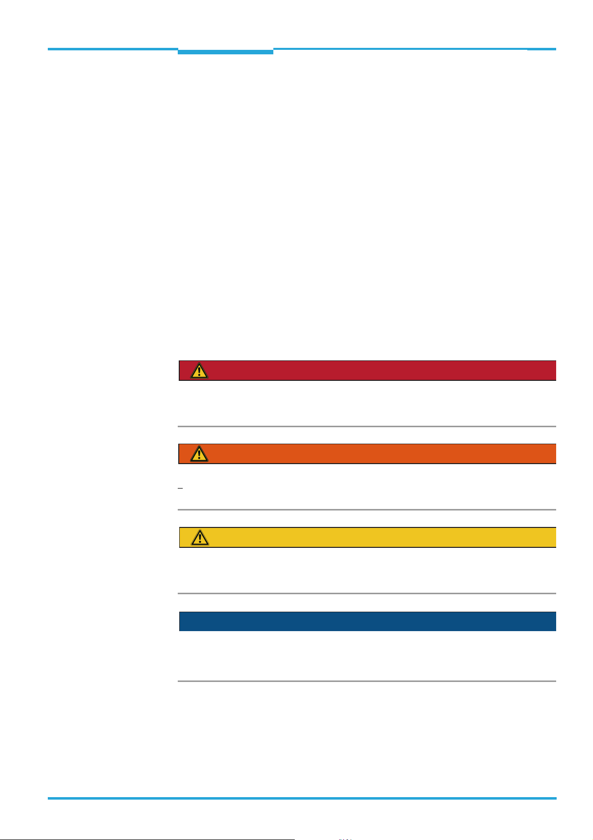
2.3 Laser Warning
Optical radiation: Laser class 2
The CLV61x uses a red light laser diode and corresponds to laser class 2.
The entire reading window is a laser output aperture.
The human eye is not at risk when briefly exposed to the radiation for up to 0.25 seconds.
Exposure to the laser beam for longer periods of time may cause damage to the retina. The
laser radiation is harmless to human skin.
Do not look into the laser beam intentionally.
Never point the laser beam at people's eyes.
If it is not possible to avoid looking directly into the laser beam, e.g., during commission-
ing and maintenance work, suitable eye protection must be worn.
Avoid laser beam reflections caused by reflective surfaces. Be particularly careful dur-
ing mounting and alignment work.
Do not open the housing. Opening the housing will not switch off the laser. Opening the
housing may increase the level of risk.
Current national regulations regarding laser protection must be observed.
Caution – incorrect use can lead to the user being exposed to dangerous radiation.
Important! Maintenance is not necessary to ensure compliance with laser class 2.
8 © SICK AG · Germany · All rights reserved · Subject to change without notice 8015592/ZNI9/2017-06-13
Page 9
Technical Information Chapter 2
Safety Information
CLV61x
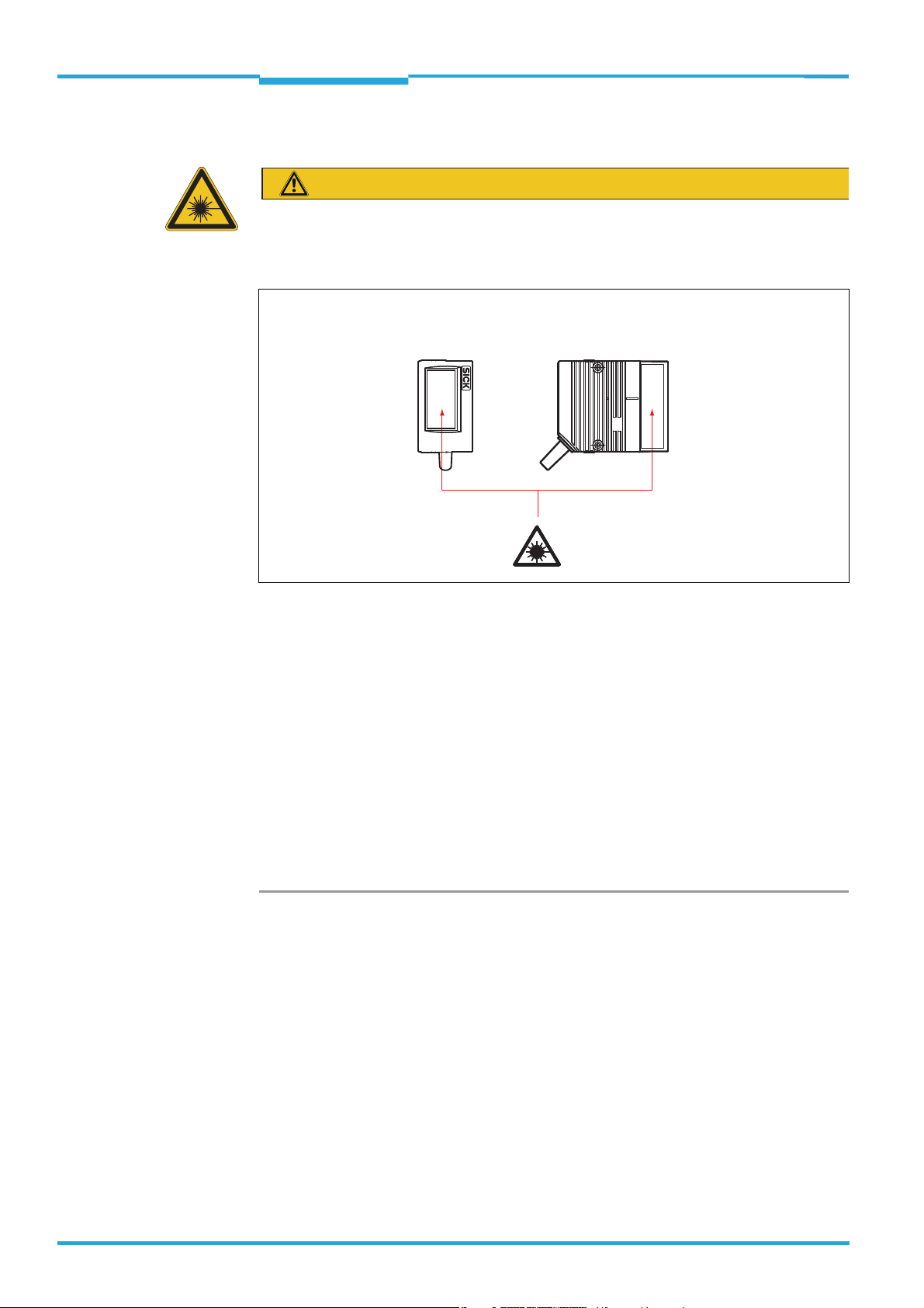
Laser Warning and Laser Specifications Labels
Installation site and design of the combination of black and yellow laser warning label and
type label with laser performance data:
CLV610-C0000
P/N: 1057125
D-79276 Reute
Made in Germany
S/N: 1540 0001
DC 10...30V
2.8W Imax=700mA
Pmax=1.5mW
Manufactured: October 2015
= 655nmλ
P<1.0mW average
Pulse duration <300μs
Laser performance data
Meaning of the laser warning label:
Laser radiation - Do not look into the laser beam - laser class 2.
Controlling the Laser Diode
In real operation (triggered reading mode), the CLV61x switches the laser diode on and off
again with the trigger signals of the conveyor system (object in reading range). Triggering occurs here via the switching inputs of the CLV61x or by a command via one of the data interfaces.
A laser timeout configured with SOPAS ET (device page I
LLUMINATION CONTROL) can be used
to automatically switch off the laser diode for this type of object trigger control if the pulse
has stopped for too long (e.g., conveyor system has stopped). The current internal reading
interval of the CLV61x remains open. If the function is activated, the laser timeout is 10 min
in the default settings.
The laser diode is permanently or repeatedly switched on in the following device statuses:
In the "Percentage Evaluation" and "Auto Setup" operating modes (only used temporar-
ily for configuration/diagnosis)
In reading operation in the pulsing types "Auto cycle" (adjustable pulse/pause ratio) or
"free".
If timeout is activated, it will have no effect here.
Important! The CLV61x has no optical indicator (LED) for laser diode activity.
8015592/ZNI9/2017-06-13 © SICK AG · Germany · All rights reserved · Subject to change without notice 9
Page 10

Chapter 2 Technical Information
Safety Information
CLV61x bar code scanner
10 © SICK AG · Germany · All rights reserved · Subject to change without notice 8015592/ZNI9/2017-06-13
Page 11

Technical Information Chapter 3
CLV61x
Mounting
3 Mounting
3.1 Notes on Mounting
The permitted ambient conditions for the operation of the CLV61x must be complied
with e.g., temperature, radiated emission, ground potential in situ.
See "CLV61x bar code scanner" operating instructions (no. 8015589)
The device must only be mounted to the optional SICK brackets using the pairs of
threaded mounting holes provided for this purpose.
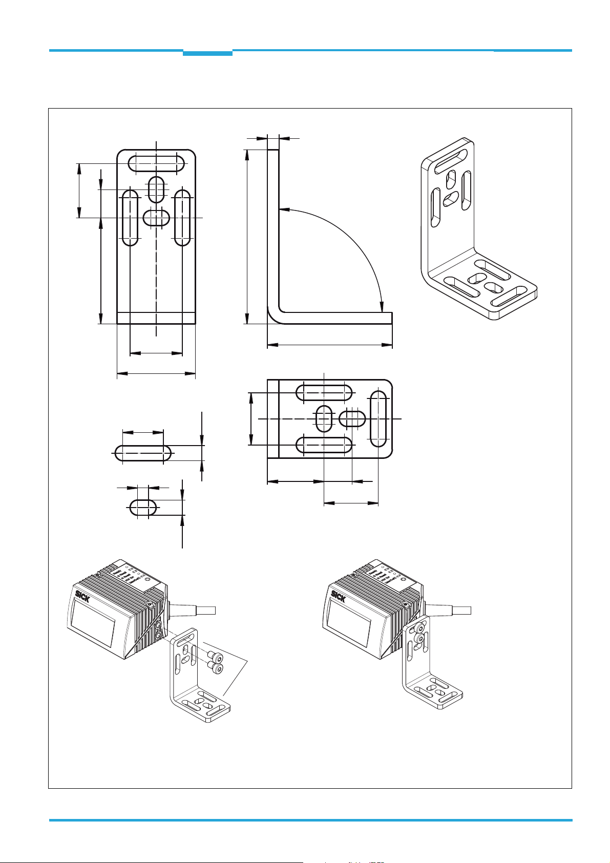
3.2 Optional Accessories
For fastening the CLV61x directly to a mounting device (base) 4 SICK brackets in all are
available (see the following pages).
Brackets for optional Mirror Hood No. 2046811
Views and dimensions of the two corresponding brackets no. 2048633 and no. 2046822
for the CLV6xx optional mirror hood are shown in the fitting instructions for "External mirror
hood for bar code scanners of the CLV6xx family " (no. 8013180, Ger./Engl. version).
8015592/ZNI9/2017-06-13 © SICK AG · Germany · All rights reserved · Subject to change without notice 11
Page 12
Chapter 3 Technical Information
(19)
(3.5)
10
11
4
(AF3)
38
10
48
16
22
10
19
(M5)
(Ø 7.5)
2
1
(SW3)
1
2
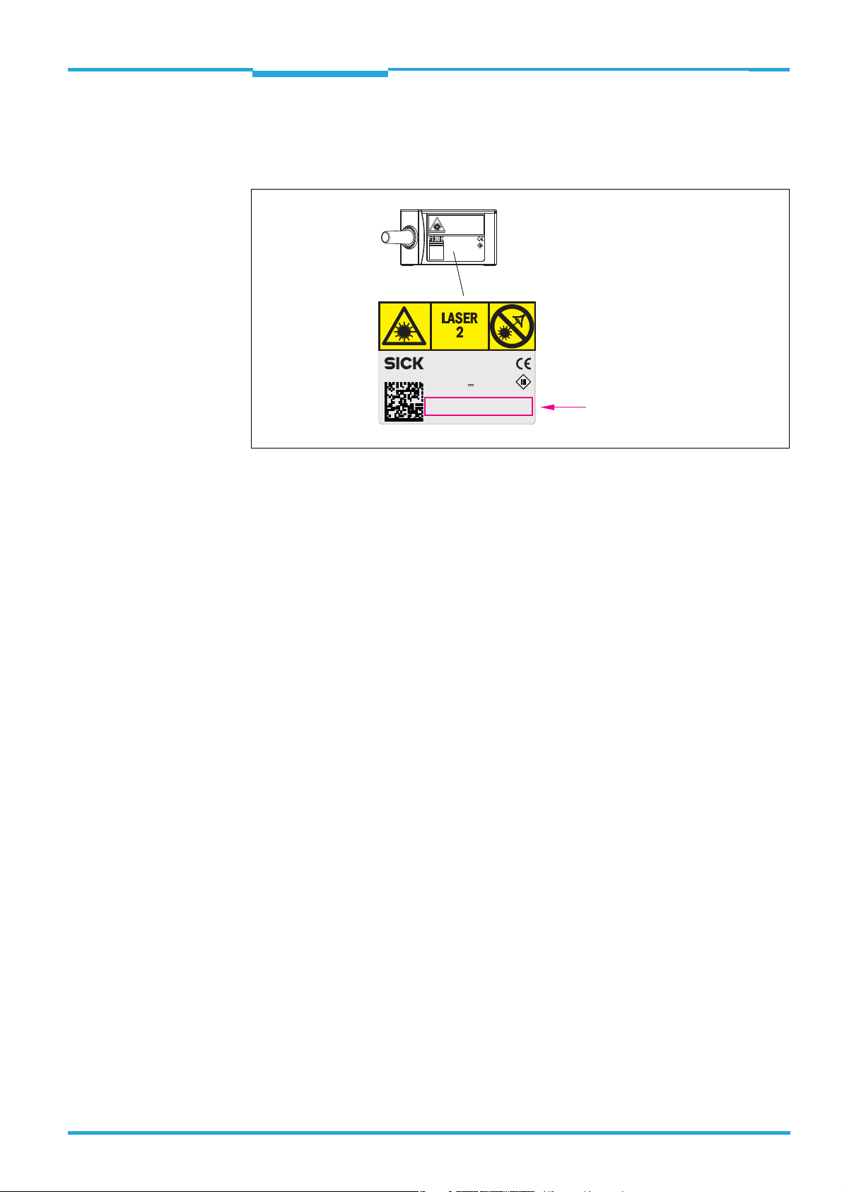
Quick release clamp
no. 2025526 (parts 1 and 2),
can be adjusted in 90°-steps
Bracket no. 2020410,
each angle leg adjustable in 90°
steps. Here shown as supplement.
Included to fix the bar code scanner to the quick release clamp:
2 x cylinder head screws M5 x 8, with hexagon socket (AF3), self-locking
M5, screw-in depth max. 8 mm
All length measures in mm
Mounting sample
(Bracket no. 2020410
not included in delivery
of quick release clamp)
Mounting
CLV61x bar code scanner
3.2.1 Dimensional Drawing of Quick Release Clamp No. 2025526
12 © SICK AG · Germany · All rights reserved · Subject to change without notice 8015592/ZNI9/2017-06-13
Page 13
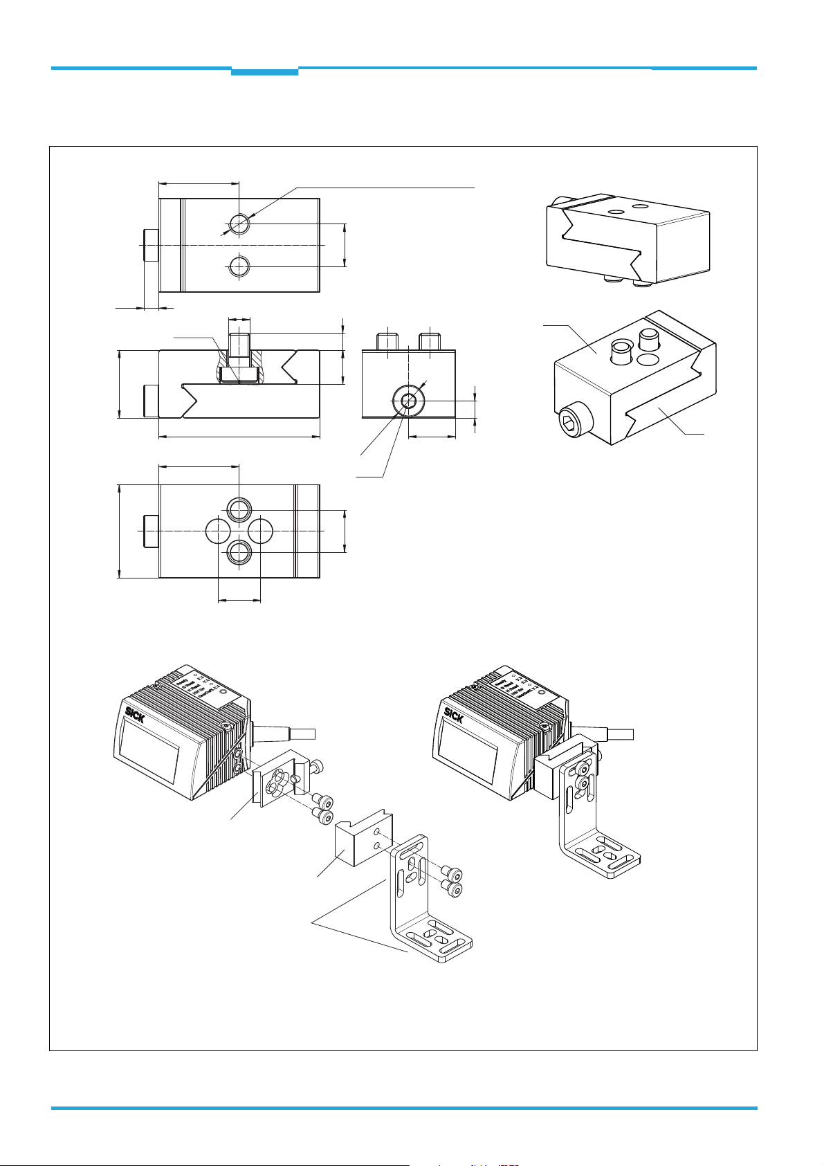
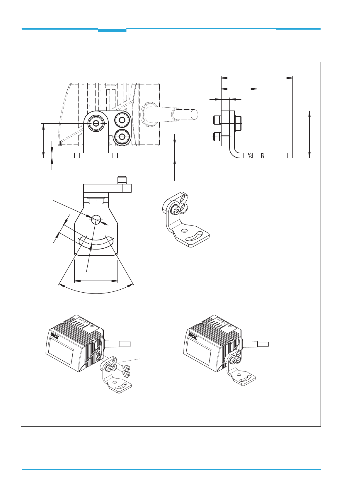
Included to fix the bar code scanner to the bracket:
2 x cylinder head screws M5 x 8, with hexagon socket (AF3), self-locking
43
60
4
90°
36.5
27
18
18.7
9.7
3.8
5.2
14
Elongated hole:
5.2
large:
small:
18
18.7
9.719.5
Mounting sample
All length measures in mm
Angle leg
adjustable in
90°steps
Technical Information Chapter 3
CLV61x
Mounting
3.2.2 Dimensional Drawing of Bracket No. 2020410
8015592/ZNI9/2017-06-13 © SICK AG · Germany · All rights reserved · Subject to change without notice 13
Page 14
Chapter 3 Technical Information
Included to fix the bar code scanner to the adapter plate:
2 x cylinder head screws M5 x 6, with hexagon head (AF3), self-locking
Mounting sample
All length measures in mm
Adapter plate
can be swivelled
and fixed freely
at the angle
20.8
3
(7.3)
43
21.5
5
28.3
26
60°
5.5
Ø 5.5
R 15
Mounting
CLV61x bar code scanner
3.2.3 Dimensional Drawing of the Bracket with Adapter Plate No. 2042902
14 © SICK AG · Germany · All rights reserved · Subject to change without notice 8015592/ZNI9/2017-06-13
Page 15
Technical Information Chapter 3
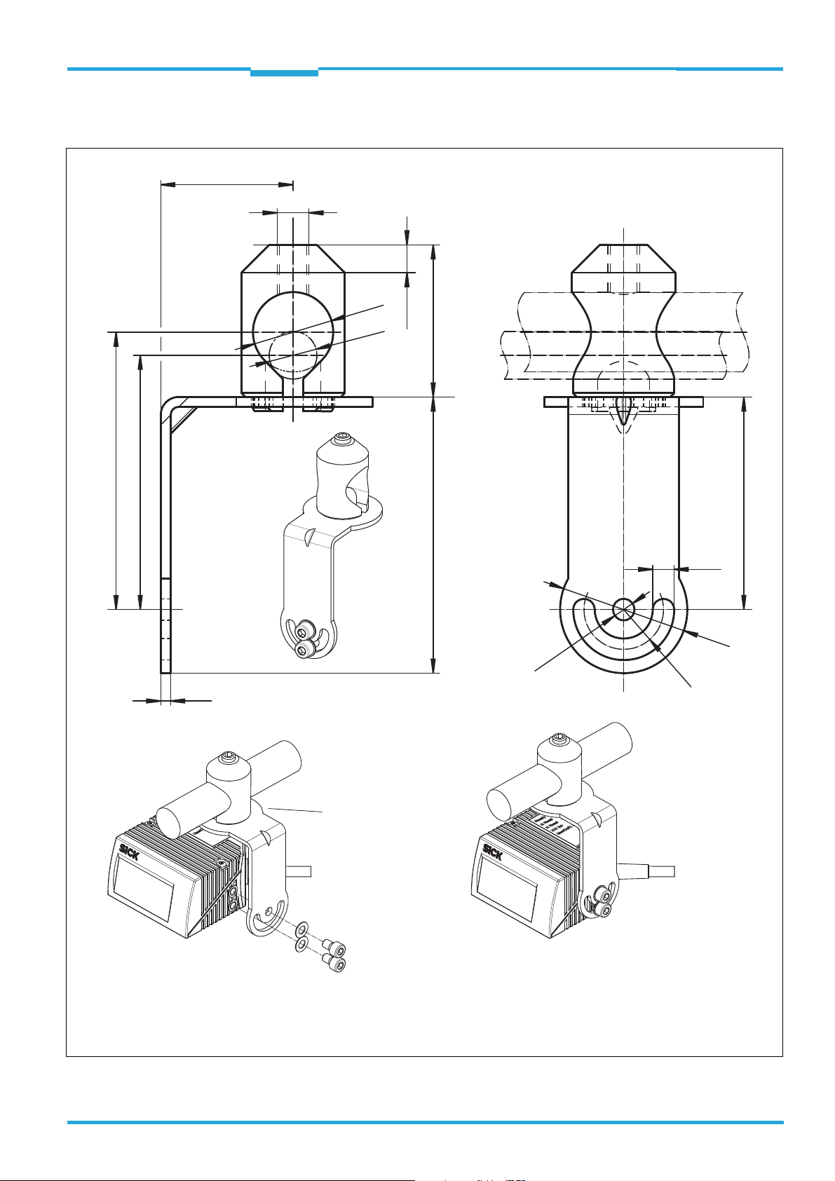
Ø
5. 4
R 10
5.4
53.5
Ø
32
Included to fix the bar code scanner to the bracket:
2 x cylinder head screws M5 x 8, with hexagan socket (AF3), self-locking
Mounting sample
All length measures in mm
Bracket can be
swivelled and fixed
freely on the rod
clamp
(rod not included in delivery)
33.3
38.369.5
Ø 20
Ø 12
M8
64
69.8
2.5
7 x 45°
Mounting
CLV61x
3.2.4 Dimensional Drawing of the Bracket with Rod Clamp No. 2042802
s
8015592/ZNI9/2017-06-13 © SICK AG · Germany · All rights reserved · Subject to change without notice 15
Page 16

Chapter 3 Technical Information
Mounting
CLV61x bar code scanner
3.3 Mounting the CDB620-001 or CDM420-0001 Connection Module
The mounting location for the connection module (distance to CLV61x) depends on the
physical design (RS-232) of the both serial data interfaces AUX and HOST and the transmission rates used:
Recommended cable length between CLV61x and connection module:
Max. 5 m when using max. data transmission rate 115.2 kBd of the HOST interface.
(fixed data transmission of AUX interface: 57.6 kBd)
For detailed information on mounting and the electrical installation of the connection module, please see:
"CDB620 connection module" operating instructions (part no. 8012119, Ger./Engl.
version) e.g. via www.sick.com/CDB
"CDM420-0001 connection module" operating instructions (part no. 8010004, Ger./
Engl. version) e.g. via www.sick.com/CDM
The corresponding operating instructions are enclosed in printed form with the connection
modules.
16 © SICK AG · Germany · All rights reserved · Subject to change without notice 8015592/ZNI9/2017-06-13
Page 17

Technical Information Chapter 4
CLV61x
Electrical installation
4 Electrical installation
4.1 Notes on the Electrical Installation
The electrical installation must only be performed by qualified electricians.
The currently applicable safety regulations must be observed when working in electri-
cal systems!
Electrical connections between the CLV61x and other devices must only be created and
disconnected when there is no power to the system. Otherwise, the devices may be
damaged.
When using extension cables with open ends, ensure that bare wire ends do not come
into contact with each other (risk of short-circuit when supply voltage is switched on!).
Wires must be appropriately insulated from each other.
Wire cross sections of the supply cable from the customer's power system should be
designed in accordance with the applicable standards.
In order to retain the IP 65 enclosure rating for the CLV61x connecting cable even when
using an extension cable (e.g., no. 2043413, 2 m), insert rubber seal no. 4038847 between the plug and socket of the D-Sub plug connection of the cables and screw in the
plug connection.
Circuits connected to the CLV61x must be designed as SELV circuits (SELV = Safety
Extra Low Voltage).
Do not switch on the supply voltage for the CLV61x/the CDB620-001/CDM420-0001
connection module until the connection work has been completed and the wiring work
has been tested thoroughly.
8015592/ZNI9/2017-06-13 © SICK AG · Germany · All rights reserved · Subject to change without notice 17
Page 18

Chapter 4 Technical Information
Input 2
(e.g. incremental encoder,
Teach-in matchcode)
Input 1
(e.g. external reading clock)
Output 1
(e.g. indicator lamp)
Output 2
(e.g. indicator lamp)
CLV61x ECO/CAN
CDB620
Connection module
SerialSerial
Configuration
Diagnostics
SOPASSOPAS
SerialSerial
“HOST (RS-232)/
AUX (RS-232)/
I/O”
...
...
1
2
DC 10 V ... 30 V
GND
HOST
PC
Furt her d ata
processing
e.g. cable no. 2014054 (2 m)
“AUX” (RS-232)
DC 10 V ... 30 V
Switching inputs/outputs = digital
“HOST” (RS-232)
Reading result
“CAN” (CLV61x CAN only)
CAN Sensor Network
CLV61x
Aux
RS-232
RS-232
CAN
*)
SOPAS ET
Configuration
Software
Further data
processing
Host
PC
HOST
*) CLV61x CAN and FIELDBUS series
◂ Configuration/data output ▸
◂ Configuration/data output ▸
Electrical installation
CLV61x bar code scanner
4.2 Overview of all lnterfaces and Connection Options
CLV61x ECO/CAN
CLV61x FIELDBUS
CLV61 FIELDBUS
DC 10 V ... 30 V
CAN Sensor Network
Input 1
(e.g. external reading clock)
Using the Data Interfaces
“AUX (RS-232)/
CAN/DC 10 V ... 30 V”
CDF600-21xx
PROFIBUS
Fieldbus module
PROFIBUS
“AUX” (USB)
e.g. cable
no. 6036106
(2 m)
Reading result
PROFIBUS
SOPASSOPAS
PC
Configuration
Diagnostics
Furt her d ata
processing
PLC
18 © SICK AG · Germany · All rights reserved · Subject to change without notice 8015592/ZNI9/2017-06-13
Page 19

Technical Information Chapter 4
Electrical installation
CLV61x
Possible interface HOST AUX
Assignable function
RS-232 RS-232
Read result output (format 1)
Read result output (format 2)
Read diagnosis output (fixed format)
Monitoring of HOST interface traffic
Communication with fieldbus module
CDF600-21xx PROFIBUS
Configuration (SOPAS, commands)
= Output of the same function simultaneously possible via the interfaces
= Access only via one of the interfaces (CLV61x
FIELDBUS serie)
= Access only makes practical sense via one of the interfaces (risk of collision)
Important Only one of several selectable functions can be allocated to each interface.
4.3 Pin Assignments of the 15-pin D-Sub HD Plug (Connection Cable)
CLV61x ECO
15-pin D-Sub HD plug
6
10
5
1
15
11
1
DC 10 V ... 30 V
2
RxD (RS-232), AUX
3
TxD (RS-232), AUX
4
Sensor 2 (switching input)
5
GND
6
N.C.
7
RxD (RS-232), HOST
8
N.C.
9
10
11
12
13
14
15
TxD (RS-232), HOST
N.C.
N.C.
Result 1 (switching output)
Result 2 (switching output)
Sensor 1 (switching input)
SensGND
CLV61x CAN / FIELDBUS
15-pin D-Sub HD plug
6
10
5
1
15
11
1
DC 10 V ... 30 V
2
RxD (RS-232), AUX
3
TxD (RS-232), AUX
4
Sensor 2 (switching input)
5
GND
6
N.C.
7
RxD (RS-232), HOST
8
N.C.
9
10
11
12
13
14
15
TxD (RS-232), HOST
CAN_H
CAN_L
Result 1 (switching output)
Result 2 (switching output)
Sensor 1 (switching input)
SensGND
N.C. = not connected
Shield of the CLV61x contacted with metal housing of 15-pin D-Sub HD plug.
8015592/ZNI9/2017-06-13 © SICK AG · Germany · All rights reserved · Subject to change without notice 19
Page 20

Chapter 4 Technical Information
15-pin D-Sub HD socket
(front view)
Braid shield contacted with metal housing of socket.
110
15611
5
9-pin D-Sub socket
(front view)
5
1
9
6
Electrical installation
CLV61x bar code scanner
4.4 Pin Assignments and Lead Color Assignments of Cables
4.4.1 Connection: CLV61x to a customer-specific Connection Box
Extension Cable No. 2043413 (2 m), open end
ss
Pin Signal Function Color of lead
1 DC 10 V ... 30 V Supply voltage Red
2 RxD (RS-232), Aux AUX interface (receiver) Purple
3 TxD (RS-232), Aux AUX interface (transmitter) Yellow
4 Sensor 2 Switching input 2 Red + black
5GND Ground Black
6N.c. – Light blue
7 RxD (RS-232), Host HOST interface (receiver) Blue
8 N.c. – Light gray or turquoise
9 TxD (RS-232), Host Host interface (transmitter) Green
10
11
CAN H
CAN L
*)
*)
12 Result 1 Switching output 1 Brown
13 Result 2 Switching output 2 Orange
14 Sensor 1 Switching input 1 White
15 SensGND Common ground for all switch-
*) Only with CLV61x CAN and CLV61x FIELDBUS series
CAN-Bus (IN/OUT) Gray
CAN-Bus (IN/OUT) Pink
White + black
ing inputs
20 © SICK AG · Germany · All rights reserved · Subject to change without notice 8015592/ZNI9/2017-06-13
4.4.2 Connection: CDB620-001 Connection Module to PC (HOST interface RS-232)
RS-232 Data Cable No. 2030319 (3 m), open end
Pin Signal Function Color of lead CDB620-001 terminals/
CDM420-0001 terminal
1– – – –
2 RxD (RS-232) Host interface (receiver) Brown 43 / 34 (TxD Host)
3 TxD (RS-232) Host interface (transmitter) Blue 44 / 35 (RxD Host)
4– – – –
5 GND Ground Black 42 / 36 (GND)
6 ... 9 – – – –
Page 21

Technical Information Chapter 4
DANGER
CLV61x
closed current loop
with equalizing currents
via cable shield
grounding point 2
grounding point 1
grounding potential difference
PLC
Reading clock
sensor
I
U
CDB620-
001
= metal housing = plastic housing
= shielded electrical cable
CLV61x
Electrical installation
4.5 Prerequisites for the Safe Operation of the CLV61x in aSystem
Risk of Injury/Risk of Damage due to Electrical Current!
Incorrect grounding of the CLV61x can, due to equipotential bonding currents between the
CLV61x and other grounded devices in the system, place the metal housing under a dangerous voltage, cause malfunction and destruction of devices as well as damage to the cable shielding through heating, and thus cause cable fires.
Work on the electrical system must only be performed by qualified electricians.
Ensure ground potential at all grounding points.
In the event of damage to the cable insulation, immediately switch off the power supply
and have the damage repaired.
Where local conditions are unfavorable and thus do not meet conditions for a safe
earthing method (same ground potential at all grounding points), take measures in
accordance with the following explanations.
The CLV61x is designed and tested for electrical safety according to EN 60950-1: 2011-01.
It is connected to the peripheral devices (power supply, reading pulse sensor(s), PLC, Host
etc.) via shielded cables. The cable shield, for example, for the data cable rests against the
metal housing of the CLV61x. The device can either be grounded through the cable shield
or through one of the threaded blind holes.
If the peripheral devices have metal housings and if the cable shields also lie on their housings, it is assumed that all devices involved in the installation have the same ground poten-
tial.
This is achieved for instance by complying with the following conditions:
Mounting the devices on conductive metal surfaces
Correctly grounding the devices/metal surfaces in the system
If necessary, low-impedance and current carrying equipotential bonding between areas
with different ground potentials.
8015592/ZNI9/2017-06-13 © SICK AG · Germany · All rights reserved · Subject to change without notice 21
Page 22

Chapter 4 Technical Information
grounding point 1
Electro-
optical
signal
isolator
Electro-
optical
signal
isolator
PLC
Reading
clock sensor
grounding point 2
CLV61x
shielded electrial cablemetal housing fiber optic cable
Electrical installation
CLV61x bar code scanner
If these conditions are not met, e.g. on devices in a widely distributed system over several
buildings, potential equalization currents may, due to different ground potentials, flow along
the cable shields between the devices, which can lead to hazards.
Remedial Measures
The most common solution to prevent potential equalization currents on cable shields is to
ensure low-impedance and current carrying equipotential bonding. If this is not possible, the
following solution approaches serve as a suggestion.
Important! We expressly advise against opening up the cable shields. Doing this means that the EMC
limit values can no longer be complied with and that the safe operation of the device data
interfaces can no longer be guaranteed.
a) Measures for widely distributed System Installations
On widely distributed system installations with correspondingly large potential differences,
we recommend setting up local islands and connecting them using commercially available
electro-optical signal isolators. This measure achieves a high degree of resistance to electromagnetic interference while at the same time complying with all the requirements of
EN 60950-1.
The ground loop is isolated by using the electro-optical signal isolator between the islands.
Within the islands, a stable equipotential bonding prevents equalizing currents at the cable
shields.
22 © SICK AG · Germany · All rights reserved · Subject to change without notice 8015592/ZNI9/2017-06-13
Page 23

Technical Information Chapter 4
electrically
insulatetd
grounding point 2 grounding point 3grounding point 1
grounding potential difference
U
shielded electrial cable
PLC
Reading clock
sensor
CLV61x
CLV61x
Electrical installation
b) Measures for small System Installations
For smaller installations with only slight potential differences, insulated installation of the
CLV61x and of peripheral devices may be a sufficient solution.
Even in the event of large differences in the ground potential, ground loops are effectively
prevented, meaning that equalizing currents can no longer flow via the cable shields and
metal housing.
Important! The power supply for the CLV61x and the connected peripheral devices must also guaran-
tee the required level of insulation.
Under certain circumstances, a tangible potential can develop between the insulated metal
housings and the local ground potential.
Special national Regulations for Sweden and Norway
Varning och atjarder
Utrustning som ar kopplad till skyddsjord via jordat vagguttag och/eller via annan utrustning
och samtidigt ar kopplad till kabel-TV nat kan i vissa fall medfora risk for brand.
For att undvika detta skall vid anslutning av utrustningen till kabel-TV nat galvanisk iso-
lator finnas mellan utrustningen och kabel-TV natet.
Advarsel og tiltaker
Utstyr som er koplet til beskyttelsesjord via nettplugg og/eller via annet jordtilkoplet utstyr
- og er tilkoplet et kabel - TV nett, kan forarsake brannfare.
For a unnga dette skal det ved tilkopling av utstyret til kabel-TV nettet installeres en gal-
vanisk isolator mellom utstyret og kabel-TV nettet.
8015592/ZNI9/2017-06-13 © SICK AG · Germany · All rights reserved · Subject to change without notice 23
Corresponding English Translation
Devices which are connected to the electrical system PE of the building via a mains connection or other devices with a connection to the PE, and which are connected to a cable distribution system with coaxial cables, can under certain circumstances cause a risk of fire.
Connections to a cable distribution system must therefore be made such that electrical
insulation is offered below a certain frequency range (galvanic separating link).
Page 24

Chapter 4 Technical Information
“DC 10 V ... 30 V”
“Sensor 2”
“Host 1” (serial)
“Aux 1” (serial)
“Result 2”
“Result 1”
“CAN”
1)
“Sensor 2”
“Sensor 1”
“External input 2”
2)
“External input 1”
2)
“Sensor 1”
DC 10 V ... 30 V
Application
Scanner
Interfaces
“AUX”
PC
HOST/PLC
PLC
CAN bus
1)
PLC
“Result 1”
“Result 2”
PLC
PLC
“External output 1”
2)
“External output 2”
2)
CDB620-001/CDM420-0001
Connection module
CLV61x
Photoelectric
switch
Reading clock
Incremental
encoder
Path increment
Further
functions
“HOST” (serial)
“AUX” (serial)
RS-232
RS-232
CMC600
1) NOT for CLV61x ECO series
2) An optional CMC600 Parameter Cloning Module is required to provide the additional switching inputs and outputs
Futher data
processing
Configuration
Diagnosis
2)
Electrical installation
CLV61x bar code scanner
4.6 Installation steps
4.6.1 Block diagram: Wiring the CDB620-001/CDM420-0001 Connection Module
The commissioning/configuration of the connection modules as well as the technical data
are described in the:
"CDB620 connection module" operating instructions (part no. 8012119, Ger./Engl.
version) e.g. via www.sick.com/CDB
"CDM420-0001 connection module" operating instructions (part no. 8010004, Ger./
Engl. version) e.g. via www.sick.com/CDM.
The corresponding operating instructions are enclosed in printed form with the connection
modules.
Important! Wiring the Signals without SICK Connection Module
If a customer-specific connection box is used, the wiring in principle of the data interfaces
and switching interfaces signals can be designed according to the following wiring diagrams
for the SICK connection modules (from page 29 on).
If the 15-pin D-Sub HD plug of the CLV61x is not compatible with the customer-specific connection box, the extension cable no. 2043413 (2 m) with corresponding socket and open
leads is available. See Chapter 4.4.1 Connection: CLV61x to a customer-specific Connec-
tion Box, Page 20.
24 © SICK AG · Germany · All rights reserved · Subject to change without notice 8015592/ZNI9/2017-06-13
Page 25

Technical Information Chapter 4
CLV61x
Electrical installation
4.6.2 Connecting the Supply Voltage
The CLV61x requires a power supply unit with the following characteristics:
Supply voltage DC 10 V to 30 V (stabilized safety extra-low voltage [SELV]).
The power supply unit must satisfy the requirements of SELV in accordance with the
currently applicable EN 60950-1.
The power source must be able to provide at least 3.5 W output or max. 700 mA.
Additional 0.5 W output power when using the optional CMC600 parameter cloning
module in the CDB620-001 or CDM420-0001 connection module.
Protection of Supply Cables
To ensure protection against short-circuits/overload in the supply cables from the customer's power system, the lead cross sections used have to be selected and protected
according to the national standards.
The supply voltage is fed via the connection module, for to do so please see:
Connection module Interface Chapter
CDB620-001 Supply voltage
CDM420-0001 Supply voltage
Chapter 4.7.2 Wiring the Supply Voltage in the CDB620001 Connection Module, Page 30
Chapter 4.8.2 Wiring the Supply Voltage in the CDM4200001 Connection Module, Page 41
The connection modules have each one fuse (0.8 A slow blow) in the electrical circuit downstream of the S1 switch.
Wiring without SICK Connection Module
The CLV61x must be protected using a separate fuse of max. 2 A slow blow, in the supplying
circuit at the start of the supply cable.
8015592/ZNI9/2017-06-13 © SICK AG · Germany · All rights reserved · Subject to change without notice 25
Page 26

Chapter 4 Technical Information
NOTICE
Electrical installation
CLV61x bar code scanner
4.6.3 Wiring serial Data Interfaces
The maximum data transmission rate for the serial interface depends on the cable length
and on the type of interface (RS-232). The following recommendations apply:
Type of interface Data transmission rate Distance to the target computer (Host)
RS-232 Up to 19.2 kBd
38.4 kBd ... 115.2 kBd
Max. 10 m
Max. 5 m
Risk of Damage to Internal Interface Module
If the serial data interfaces are wired incorrectly, then electronic components of the CLV61x
could get damaged.
Observe the information on wiring.
Carefully check the wiring prior to switching on the CLV61x.
The wiring is done using the connection module, for to do so please see:
Connection module Data interface Chapter
CDB620-001 RS-232
CDM420-0001 RS-232
Chapter 4.7.3 Wiring the RS-232 serial Host Data Interface in the CDB620-001 Connection Module, Page 30
Chapter 4.8.3 Wiring the RS-232 Serial Host Data Interface in the CDM420-0001 Connection Module, Page 41
Recommendation Use shielded data cables (twisted pair leads).
To prevent interference factors, do not lay data cables over a longer route in parallel
with power supply cables and motor cables, in cable channels, for example.
4.6.4 Wiring the Digital Switching Inputs
The two physical switching inputs "Sensor 1" and "Sensor 2" of the CLV61x can be used for
starting and/or ending the reading clock or for connecting an incremental signal.
Expansion: Additional logical switching inputs in the CLV61x converted to physical "external“ switching inputs in the optional connection module
Thanks to the optional CMC600 parameter cloning module in combination with the
CDB620-001/CDM420-0001 connection module, the two additional switching inputs
"External input 1" and "External input 2" on the terminals in the connection module are available.
Important! These two external switching inputs are not suitable for time critical applications.
The wiring of the switching inputs is done using the connection module, please see:
26 © SICK AG · Germany · All rights reserved · Subject to change without notice 8015592/ZNI9/2017-06-13
Page 27

Technical Information Chapter 4
CLV61x
Electrical installation
Connection module Switching input Chapter
CDB620-001 Sensor 1
Sensor 2
External input 1
(„Ext. In 1“)
External input 2
(„Ext. In 2“)
CDM420-0001 Sensor 1
Sensor 2
External input 1
(„Aux In 1“)
External input 2
(„Aux In 2“)
Chapter 4.7.5 Wiring the "Sensor 1" Switching Input in
the CDB620-001 Connection Module, Page 32
Chapter 4.7.6 Wiring the "Sensor 2" Switching Input in
the CDB620-001 Connection Module, Page 33
Chapter 4.7.7 Wiring the "External input 1" Switching
Input in the CDB620-001 Connection Module, Page 34
Chapter 4.7.8 Wiring the "External input 2" Switching
Input in the CDB620-001 Connection Module, Page 35
Chapter 4.8.5 Wiring the "Sensor 1" Switching Input in
the CDM420-0001 Connection Module, Page 43
Chapter 4.8.6 Wiring the "Sensor 2" Switching Input in
the CDM420-0001 Connection Module, Page 44
Chapter 4.8.7 Wiring the "External input 1" Switching
Input in the CDM420-0001 Connection Module,
Page 45
Chapter 4.8.8 Wiring the "External input 2" Switching
Input in the CDM420-0001 Connection Module,
Page 46
4.6.5 Wiring the Digital Switching Outputs
The two physical switching outputs "Result 1" and "Result 2" of the CLV61x can be allocated
independently of each other with various functions for the output of events in the reading
process. If the allocated event occurs, the corresponding switching output is live after the
end of the reading clock for the selected pulse duration.
Expansion: Additional logical switching outputs in the CLV61x converted to physical "external“ switching outputs in the optional connection module
Thanks to the optional CMC600 parameter cloning module in combination with the
CDB620-001/CDM420-0001 connection module, the two additional switching outputs
"External output 1" and "External output 2" on the terminals in the connection module are
available.
Important! These two external switching outputs are not suitable for time critical applications.
The wiring of the switching outputs is done using the connection module, please see:
Connection module Switching output Chapter
CDB620-001 Result 1
Result 2
External output 1
(„Ext. Out 1“)
External output 2
(„Ext. Out 2“)
Chapter 4.7.9 Wiring the "Result 1" Switching Output in
the CDB620-001 Connection Module, Page 36
Chapter 4.7.10 Wiring the "Result 2" Switching Output
in the CDB620-001 Connection Module, Page 37
Chapter 4.7.11 Wiring the "External output 1" Switching Output in the CDB620-001 Connection Module,
Page 38
Chapter 4.7.12 Wiring the "External output 2" Switching Output in the CDB620-001 connection module,
Page 39
8015592/ZNI9/2017-06-13 © SICK AG · Germany · All rights reserved · Subject to change without notice 27
Page 28

Chapter 4 Technical Information
Electrical installation
Connection module Switching output Chapter
CDM420-0001 Result 1
Result 2
External Input 1
(„Aux Out 1“)
External Input 2
(„Aux Out 2“)
Chapter 4.8.9 Wiring the "Result 1" Switching Output in
the CDM420-0001 Connection Module, Page 47
Chapter 4.8.10 Wiring the "Result 2" Switching Output
in the CDM420-0001 Connection Module, Page 48
Chapter 4.8.11 Wiring the "External output 1" Switching Output in the CDM420-0001 Connection Module,
Page 49
Chapter 4.8.12 Wiring the "External output 2" Switching Output in the CDM420-0001 Connection Module,
Page 50
CLV61x bar code scanner
Important! Capacitive loads on the switching outputs have an effect on the switch-on and switch-off
behavior. The maximum capacity of 100 nF is a limit value.
28 © SICK AG · Germany · All rights reserved · Subject to change without notice 8015592/ZNI9/2017-06-13
Page 29

Technical Information Chapter 4
CDB620-001 Connection Module
CMC600 parameter cloning module
(optional)
ONOFF
POWER
S1
0.8 A T
Ter m C AN
Term 485RS
SGND - GND
422 485
ONOFF
NO
YES
ONOFF
ONOFF
S2 S3
S7S6
S4
CMC
10 11 12 13 14 15 16 17 18
Sens 1
In 1
In 2
U
IN
*
U
IN
*
Sens 2
SGND
SGND
SGND
LEDs
20 21 22 23 24
Res 1
Res 2
Out 1
Out 2
GND
30 31 32 33 34
CAN_H
CAN_L
T+
R+
GND
40 41 42 43 44
CAN_H
CAN_L
T‒/TxD
R‒/RxD
GND
SCANNER
AUX interface
6110 5
1115
5
1
9
6
U
IN
U
IN
GND
GND
Shield
Shield
Shield
Shield
1234567 8
= an CMC600 is required to provide the additional switching inputs and outputs
DC 10 V ... 30 V
External
reading
clock sensor
(e.g. photoelectric
switch)
V
S
Out
GND
Result 1
PLC
GND
Result 2
to PC
to
CLV61x
Pin
2: RxD
3: TxD
5: GND
Host
RS-232
TxD
RxD
GND
VS = DC 10 V ... 30 V on terminal UIN = UIN* after fuse F and switch S1
F
RS-232
Electrical installation
CLV61x
4.7 Using the CDB620-001 Connection Module
4.7.1 Wiring overview (one switching input used)
8015592/ZNI9/2017-06-13 © SICK AG · Germany · All rights reserved · Subject to change without notice 29
Page 30

Chapter 4 Technical Information
6
1
10
5
11
15
CLV61x
CDB620
VS
V
S
1
5
5
Shield
1U
IN
2 GND
UIN*
GND
S1
F
Shield
D-Sub HD plug,
15-pin
GND
.
.
.
.
.
.
ON
OFF
S1 : POWER
DC 10 V to 30 V
UIN*
Switch S1:
ON:
Power supply voltage U
IN
switched to UIN* via fuse to CDB620 and CLV61x.
Power supply voltage U
IN
* additionally available on terminals 11 and 14.
OFF:
CDB620 and CLV61x disconnected from power supply voltage.
Recommended position during all electrical installation work.
POWER
VS = DC 10 V to 30 V on terminal UIN = UIN* after fuse F and switch S1
6
1
10
5
11
15
CLV61x CDB620 Host
D-Sub
HD plug,
15-pin
5
.
.
.
TxD
RxD
RxD
TxD
GND
GND
GND
9
7
43
T‒/TxD
44
R
‒/RxD
42
GND
6
Shield
RS-232 RS-232
422
485
S6 : RS
ON
OFF
S7: Term 485
S6
422485
Electrical installation
CLV61x bar code scanner
4.7.2 Wiring the Supply Voltage in the CDB620-001 Connection Module
4.7.3 Wiring the RS-232 serial Host Data Interface in the CDB620-001 Connection Module
30 © SICK AG · Germany · All rights reserved · Subject to change without notice 8015592/ZNI9/2017-06-13
Page 31

Technical Information Chapter 4
amongst
others
CAN
amongst
others
CAN
amongst
others
CAN
Host
Shield
30 31 32 6
30 31 32 6
30 31 32 6
33
34
43
44
6
30 31 32 6
40 41 42 7
40 41 42 7
CDB620
CDB620
CDB620
(Slave)
(Slave)
(Slave)
GN = 01
CLV61x CAN
CLV61x FIELDBUS
CLV61x CAN
CLV61x FIELDBUS
CLV61x CAN
CLV61x FIELDBUS
CLV61x CAN
CLV61x FIELDBUS
(Master)
GN = 63
GN = 02
GN = 03
(max. 32 participants)
Switch
ON
OFF
S2 (TermCAN):
Switch
ON
OFF
S2 (TermCAN):
Switch
ON
OFF
S2 (TermCAN):
21 22 23 6
31 32 33 7
CDM420
Switch
ON
OFF
S4 (TermCAN):
CAN_H
CAN_L
Shield
GND
CAN_H
CAN_L
Shield
GND
CAN_H
CAN_L
Shield
GND
CAN_H
CAN_L
Shield
GND
CAN_H
CAN_L
Shield
GND
GND
GND
RxD
TxD
RS-232
T‒/TxD
R‒/RxD
T+
R+
CDB620
42
CAN
CAN
CAN
amongst
others
CAN
Connection of power supplies as well
as of reading clock sensor e.g. to the
master here not shown.
Switch
ON
OFF
S2 (TermCAN):
Serial Host interface
Alternative connection module:
422
485
S6 (RS):
GN = Device number
Stub
CLV61x
Electrical installation
4.7.4 Wiring the CAN Data Interface in the CDB620-001 Connection Module
8015592/ZNI9/2017-06-13 © SICK AG · Germany · All rights reserved · Subject to change without notice 31
Page 32

Chapter 4 Technical Information
6
1
10
5
11
15
CLV61xCDB620
PNP sensor
V
S
VS
V
S
GND
SensGND
3.32 K
6.64 K
Sensor 1
V
in
UIN* = DC 10 V to 30 V
a) Sensor supplied by CDB620
b) Sensor connected electrically isolated/externally supplied
d) Switch connected electrically isolated/externally supplied
c) Switch supplied by CDB620
14
15
1
5
12
SGND
6
Shield
11
U
IN
*
10 Sens 1
Out
U
IN
*
GND
S3
e.g. photo-electric switch
CDB620
PNP sensor
VS
GND
Connect the switch as shown in b)
12
SGND
6
Shield
11 UIN*
10 Sens 1
Out
U
IN
*
GND
S3
e.g. photo-electric
switch
Function assignment to "Sensor 1" switching input
via SOPAS ("Sensor/Input 1"):
- Start of reading clock
- Stop of reading clock
- Start teach-in matchcode/start code comparison
- Increment input
- if required further functions in the future
UIN*
CDB620
12 SGND
6 Shield
11
U
IN
*
10
Sens 1
GND
S3
ON
OFF
S3 : SGND-GND
ON
OFF
S3 : SGND-GND
ON
OFF
S3 : SGND-GND
V
S ext
Shield
D-Sub HD plug,
15-pin
GND
.
.
.
Shield
Shield
Vin = max. 32 V
Ratings for "Sensor 1" switching input
Power fed to the input starts the assigned
function, e.g. start of reading clock.
(default setting: logic not inverted [active high],
debouncing 10 ms)
– Optodecoupled, reverse polarity protected
– Can be wired with the PNP output of a sensor
– SensGND reference potential valid for all
switching inputs
Low: V
in
≤ 2 V; Iin ≤ 0.3 mA
High: 6 V ≤ V
in
≤ 32 V;
0.7 mA ≤ I
in
≤ 5 mA
Switching
behavior
Features
Electrical
values
Switch S3: SGND-GND
ON: GND of the sensor connected to GND
of CDB620/CLV61x.
OFF: GND of the sensor connected to
SensGND of CDB620/CLV61x
(Sensor connected electrically isolated
to the CDB620/CLV61x).
Selected reference potential valid for all
switching inputs ("Sensor 1/2" and "In 1/2")
SensGND
GND
Electrical installation
CLV61x bar code scanner
4.7.5 Wiring the "Sensor 1" Switching Input in the CDB620-001 Connection Module
32 © SICK AG · Germany · All rights reserved · Subject to change without notice 8015592/ZNI9/2017-06-13
Page 33

Technical Information Chapter 4
Power fed to the input starts the assigned
function, e.g. stop of reading clock.
(default setting: logic not inverted [active high],
debouncing 10 ms)
– Optodecoupled, reverse polarity protected
– Can be wired with the PNP output of a sensor
– SensGND reference potential valid for all
switching inputs
Low: V
in
≤ 2 V; Iin ≤ 0.3 mA
High: 6 V ≤ V
in
≤ 32 V;
0.7 mA ≤ I
in
≤ 5 mA
Switching
behavior
Features
Electrical
values
6
1
10
5
11
15
CLV61xCDB620
PNP sensor
V
S
VS
V
S
GND
SensGND
3.32 K
6.64 K
Sensor 2
V
in
UIN* = DC 10 V to 30 V
a) Sensor supplied by CDB620
b) Sensor connected electrically isolated/externally supplied
d) Switch connected electrically isolated/externally supplied
c) Switch supplied by CDB620
4
15
1
5
15
SGND
7
Shield
14
U
IN
*
13 Sens 2
Out
U
IN
*
GND
S3
e.g. photo-electric switch
CDB620
PNP sensor
VS
GND
Connect the switch as shown in b)
15
SGND
7
Shield
14 UIN*
13 Sens 2
Out
U
IN
*
GND
S3
e.g. photo-electric
switch
Function assignment to "Sensor 2" switching input
via SOPAS ("Sensor/Input 2"):
- Start of reading clock
- Stop of reading clock
- Start teach-in matchcode/start code comparison
- Increment input
- if required further functions in the future
UIN*
CDB620
15 SGND
7 Shield
14
U
IN
*
13
Sens 2
GND
S3
ON
OFF
S3 : SGND-GND
ON
OFF
S3 : SGND-GND
ON
OFF
S3 : SGND-GND
V
S ext
Shield
D-Sub HD plug,
15-pin
GND
.
.
.
Shield
Shield
Vin = max. 32 V
Ratings for "Sensor 2" switching input
SensGND
Switch S3: SGND-GND
ON: GND of the sensor connected to GND
of CDB620/CLV61x.
OFF: GND of the sensor connected to
SensGND of CDB620/CLV61x
(Sensor connected electrically isolated
to the CDB620/CLV61x).
Selected reference potential valid for all
switching inputs ("Sensor 1/2" and "In 1/2")
GND
CLV61x
Electrical installation
4.7.6 Wiring the "Sensor 2" Switching Input in the CDB620-001 Connection Module
8015592/ZNI9/2017-06-13 © SICK AG · Germany · All rights reserved · Subject to change without notice 33
Page 34

Chapter 4 Technical Information
CDB620
18 SGND
8 Shield
11
U
IN
*
16
In 1
CDB620
PNP sensor
V
S
GND
18
SGND
8
Shield
11
U
IN
*
16
In 1
Out
GND
S3
e.g. photo-electric
switch
V
S ext
CLV61xCDB620
PNP sensor
VS
GND
3.32 K
6.64 K
UIN* = DC 10 V to 30 V Vin = max. 32 V
18
SGND
8
Shield
11
U
IN
*
16
In 1
Out
GND
S3
e.g. photo-electric switch
CMC600
UIN*
GND
S3
UIN*
CMC600
CMC600
UIN*
a) Sensor supplied by CDB620
b) Sensor connected electrically isolated and externally supplied
d) Switch connected electrically isolated and externally supplied
c) Switch supplied by CDB620
Connect the switch as shown in b)
Serial Aux
(RS-232)
Function assignment to "External input 1" via SOPAS:
- Start of reading clock
- Stop of reading clock
- Start teach-in matchcode/start code comparison
- if required further functions in the future
Switch S3: SGND-GND
ON: GND of the sensor connected to GND
of CDB620/CMC600.
OFF: GND of the sensor connected to
SensGND of CDB620/CMC600
(Sensor connected electrically isolated
to the CDB620/CMC600).
Selected reference potential valid for all
switching inputs ("Sensor 1/2" and "In 1/2")
ON
OFF
S3 : SGND-GND
No
YES
S4 : CMC
ON
OFF
S3 : SGND-GND
No
YES
S4 : CMC
No
YES
S4 : CMC
ON
OFF
S3 : SGND-GND
V
in
V
in
V
in
Software-controlled, the CMC600 transfers the
switching status of its physical "In 1" input
automatically via the cable to the serial Aux data
interface of the CLV61x.
The CLV61x converts the status internally to its
logical "External input 1“.
"External
input 1"
Ratings for "External input 1"
("In 1“ switching input)
Power fed to the input starts the
assigned function, e.g. start of reading
clock.
(default setting: logic not inverted
[active high], debouncing 10 ms)
– Optodecoupled, reverse polarity
protected
– Can be wired with the PNP output of
a sensor
– SensGND reference potential valid
for all switching inputs
Low: V
in
≤ 2 V; Iin ≤ 0.3 mA
High: 6 V ≤ V
in
≤ 32 V;
0.7 mA ≤ I
in
≤ 5 mA
Switching
behavior
Features
Electrical
values
SensGND
SensGND
SensGND
Electrical installation
CLV61x bar code scanner
4.7.7 Wiring the "External input 1" Switching Input in the CDB620-001 Connection Module
34 © SICK AG · Germany · All rights reserved · Subject to change without notice 8015592/ZNI9/2017-06-13
Page 35

Technical Information Chapter 4
CDB620
18 SGND
8 Shield
14
U
IN
*
17
In 2
CDB620
PNP sensor
V
S
GND
18
SGND
8
Shield
14 UIN*
17 In 2
Out
GND
S3
e.g. photo-electric
switch
V
S ext
CLV61xCDB620
PNP sensor
VS
GND
3.32 K
6.64 K
UIN* = DC 10 V to 30 V Vin = max. 32 V
18
SGND
8
Shield
14
U
IN
*
17
In 2
Out
GND
S3
e.g. photo-electric switch
CMC600
UIN*
GND
S3
UIN*
CMC600
CMC600
UIN*
a) Sensor supplied by CDB620
b) Sensor connected electrically isolated and externally supplied
d) Switch connected electrically isolated and externally supplied
c) Switch supplied by CDB620
Connect the switch as shown in b)
Serial Aux
(RS-232)
Function assignment to "External input 2" via SOPAS:
- Start of reading clock
- Stop of reading clock
- Start teach-in matchcode/start code comparison
- if required further functions in the future
Ratings for "External input 2"
("In 2“ switching input)
Power fed to the input starts the
assigned function, e.g. stop of reading
clock.
(default setting: logic not inverted
[active high], debouncing 10 ms)
– Optodecoupled, reverse polarity
protected
– Can be wired with the PNP output of
a sensor
– SensGND reference potential valid
for all switching inputs
Low: V
in
≤ 2 V; Iin ≤ 0.3 mA
High: 6 V ≤ V
in
≤ 32 V;
0.7 mA ≤ I
in
≤ 5 mA
Switching
behavior
Features
Electrical
values
ON
OFF
S3 : SGND-GND
No
YES
S4 : CMC
ON
OFF
S3 : SGND-GND
No
YES
S4 : CMC
No
YES
S4 : CMC
ON
OFF
S3 : SGND-GND
V
in
V
in
V
in
Software-controlled, the CMC600 transfers the
switching status of its physical "In 2" input
automatically via the cable to the serial Aux data
interface of the CLV61x.
The CLV61x converts the status internally to its
logical "External input 2“.
"External
input 2"
Switch S3: SGND-GND
ON: GND of the sensor connected to GND
of CDB620/CMC600.
OFF: GND of the sensor connected to
SensGND of CDB620/CMC600
(Sensor connected electrically isolated
to the CDB620/CMC600).
Selected reference potential valid for all
switching inputs ("Sensor 1/2" and "In 1/2")
SensGND
SensGND
SensGND
CLV61x
Electrical installation
4.7.8 Wiring the "External input 2" Switching Input in the CDB620-001 Connection Module
8015592/ZNI9/2017-06-13 © SICK AG · Germany · All rights reserved · Subject to change without notice 35
Page 36

Chapter 4 Technical Information
6
1
10
5
11
15
CLV61x
CDB620
U
IN
* = DC 10 V to 30 V
Load (e.g. PLC)
D-Sub HD plug,
15-pin
12
5
.
.
.
20Res 1
22
GND
5Shield
UIN*V
S
GND
Quenching circuit:
Install an anti-surge
diode directly at the
load!
For inductive load:
V
out
Result 1
GND
1
Ratings for "Result 1" switching output
PNP switching against the supply voltage V
S
(default setting: Device Ready (static),
logic: not inverted [active high])
– Short-circuit proof + temperature protected
– Galvanically not separated from V
S
0 V ≤ V
out
≤ V
S
Guaranteed:
(V
S
− 1.5 V) ≤ V
out
≤ VS with I
out
≤ 100 mA
Switching
behavior
Features
Electrical
values
Electrical installation
CLV61x bar code scanner
4.7.9 Wiring the "Result 1" Switching Output in the CDB620-001 Connection Module
36 © SICK AG · Germany · All rights reserved · Subject to change without notice 8015592/ZNI9/2017-06-13
Page 37

Technical Information Chapter 4
6
1
10
5
11
15
PNP switching against the supply voltage V
S
(default setting: Good Read, 100 ms,
logic: not inverted [active high])
– Short-circuit proof + temperature protected
– Galvanically not separated from V
S
0 V ≤ V
out
≤ V
S
Guaranteed:
(V
S
− 1.5 V) ≤ V
out
≤ VS with I
out
≤ 100 mA
Switching
behavior
Features
Electrical
values
CLV61x
CDB620
U
IN
* = DC 10 V to 30 V
Load (e.g. PLC)
D-Sub HD plug,
15-pin
13
5
.
.
.
21Res 2
22
GND
5Shield
UIN*V
S
GND
Quenching circuit:
Install an anti-surge
diode directly at the
load!
For inductive load:
V
out
Result 2
GND
1
Ratings for "Result 2" switching output
Electrical installation
CLV61x
4.7.10 Wiring the "Result 2" Switching Output in the CDB620-001 Connection Module
8015592/ZNI9/2017-06-13 © SICK AG · Germany · All rights reserved · Subject to change without notice 37
Page 38

Chapter 4 Technical Information
Load (e.g. PLC)
GND
Quenching circuit:
Install an anti-surge
diode directly at the
load!
For inductive load:
V
out
Ratings for "External output 1" ("Out 1“ switching output)
PNP switching against the supply voltage UIN*
(default setting: no function/disabled,
logic: not inverted [active high])
– Short-circuit proof + temperature protected
– Galvanically not separated from U
IN
*
0 V ≤ V
out
≤ UIN*
Guaranteed:
(U
IN
* −1.5 V) ≤ V
out
≤ UIN* with I
out
≤ 100 mA
Switching
behavior
Features
Electrical
values
CLV61x
Serial Aux
(RS-232)
CDB620
U
IN
* = DC 10 V to 30 V
CMC600
UIN*
The CLV61x indicates the switching status of its
logical "external output 1" via the serial Aux data
interface.
Software-controlled, the status is automatically
taken over by the CMC600 via the cable and
converted to the physical "Out 1" output in the
CDB620.
"External
output 1"
23Out 1
22
GND
6Shield
Electrical installation
CLV61x bar code scanner
4.7.11 Wiring the "External output 1" Switching Output in the CDB620-001 Connection Module
38 © SICK AG · Germany · All rights reserved · Subject to change without notice 8015592/ZNI9/2017-06-13
Page 39

Technical Information Chapter 4
Load (e.g. PLC)
GND
Quenching circuit:
Install an anti-surge
diode directly at the
load!
For inductive load:
V
out
Ratings for "External output 2" ("Out 2“ switching output)
PNP switching against the supply voltage UIN*
(default setting: no function/disabled,
logic: not inverted [active high])
– Short-circuit proof + temperature protected
– Galvanically not separate from U
IN
*
0 V ≤ V
out
≤ UIN*
Guaranteed:
(U
IN
* −1.5 V) ≤ V
out
≤ UIN* with I
out
≤ 100 mA
Switching
behavior
Features
Electrical
values
CLV61x
Serial Aux
(RS-232)
CDB620
U
IN
* = DC 10 V to 30 V
CMC600
UIN*
The CLV61x indicates the switching status of its
logical "external output 2" via the serial Aux data
interface.
Software-controlled, the status is automatically
taken over by the CMC600 via the cable and
converted to the physical "Out 2" output in the
CDB620.
"External
output 2"
24Out 2
22
GND
6Shield
Electrical installation
CLV61x
4.7.12 Wiring the "External output 2" Switching Output in the CDB620-001 connection module
8015592/ZNI9/2017-06-13 © SICK AG · Germany · All rights reserved · Subject to change without notice 39
Page 40

Chapter 4 Technical Information
ON
OFF
ON
OFF
ON
OFF
CDM420-0001 Connection module
CMC600 parameter cloning module
(optional)
0.8 A T
S8
No CMC ->
SCANNER
AUX interface
6110 5
1115
LEDs
31 32 33 34 35 36 37 38 39 40
T‒/TxD
R‒/RxD
+24 V*
Sensor 1
Aux Out 1
GND
GND
SGND
CAN_H
CAN_L
11 12 13 14 15 16 17 18 19 20
Result 1
Result 2
Aux In 2
Aux In 1
SGND
GND
GND
SGND
internal
internal
21 22 23 24 25 26 27 28 29 30
T+
R+
+24 V*
Sensor 2
Aux Out 2
GND
GND
SGND
CAN_H
CAN_L
1234
+24 V
+24 V
GND
GND
5678
Shield
Shield
Shield
Shield
POWER
Sensor 1
Sensor 2
Result 1
Result 2
S1
POWER
ON
OFF
S2 S3 S4 S6
ON
OFF
ON
OFF
RS485
Term422
Ter mCA N
SGND
to
CLV61x
15
69
to PC
Pin
2: RxD
3: TxD
5: GND
Result 1
PLC
GND
Result 2
External
reading clock sensor
(e.g. photo- electric switch)
V
S
Out
GND
TxD
Host
RxD
GND
RS-232
= An CMC600 is required to provide the additional switching inputs and outputs
VS = DC 10 V ... 30 V on terminal +24 V = +24 V* after fuse F and switch S1
F
V
S
= DC 10 V ... 30 V
RS-232
Electrical installation
CLV61x bar code scanner
4.8 Using the CDM420-0001 Connection Module
4.8.1 Wiring overview (one switching input used)
40 © SICK AG · Germany · All rights reserved · Subject to change without notice 8015592/ZNI9/2017-06-13
Page 41

Technical Information Chapter 4
6
1
10
5
11
15
CLV61x
CDM420-0001
VS
V
S
VS = DC 10 V to 30 V
1
5
5
Shield
1 +24 V
2 GND
+24 V*
GND
S1
F
Shield
D-Sub HD plug,
15-pin
GND
.
.
.
.
.
.
ON
OFF
S1 : POWER
DC 10 V to 30 V
+24 V*
Switch S1:
ON:
Power supply voltage U
V
(+24 V) switched as UV (+24 V*) via fuse to
CDM420-0001 and CLV61x.
U
V
(+24 V*) additionally available on terminals 29 and 39.
OFF:
CDM420-0001 and CLV61x disconnected from power supply voltage.
Recommended position during all electrical installation work.
POWER
VS on terminal "+24 V" complies with terminal "+24 V*" after fuse F and switch S1
6
1
10
5
11
15
CLV61x CDM420-0001 Host
D-Sub
HD plug,
15-pin
5
.
.
.
TxD
RxD
RxD
TxD
GND
GND
GND
9
7
34
T‒/TxD
35
R
‒/RxD
36
GND
6
Shield
RS-232
RS-232
ON
OFF
S2 : RS 485
ON
OFF
S3: Term 422
S2
OFF485
Electrical installation
CLV61x
4.8.2 Wiring the Supply Voltage in the CDM420-0001 Connection Module
4.8.3 Wiring the RS-232 Serial Host Data Interface in the CDM420-0001 Connection Module
8015592/ZNI9/2017-06-13 © SICK AG · Germany · All rights reserved · Subject to change without notice 41
Page 42

Chapter 4 Technical Information
amongst
others
CAN
amongst
others
CAN
amongst
others
CAN
amongst
others
CAN
Shield
30 31 32 6
24
25
34
35
7
40 41 42 7
CDM420
CDM420
CDM420
(Slave)
(Slave)
(Slave)
GN = 01
(Master)
GN = 63
GN = 02
GN = 03
(max. 32 participants)
Stub
Switch
ON
OFF
S4 (TermCAN):
Switch
ON
OFF
S4 (TermCAN):
Switch
ON
OFF
S4 (TermCAN):
21 22 23 6
21 22 23 6
31 32 33 7
21 22 23 6
21 22 23 6
31 32 33 7
CDB620
Switch
ON
OFF
S2 (TermCAN):
CAN_H
CAN_L
Shield
GND
CAN_H
CAN_L
Shield
GND
CAN_H
CAN_L
Shield
GND
CAN_H
CAN_L
Shield
GND
CAN_H
CAN_L
Shield
GND
GND
Host
GND
RxD
TxD
RS-232
T‒/TxD
R‒/RxD
T+
R+
CDM420
26
CAN
CAN
CAN
Switch
ON
OFF
S4 (TermCAN):
Serial Host interface
Alternative connection module:
ON
OFF
S2 (RS485):
Connection of power supplies as well
as of reading clock sensor e.g. to the
master here not shown.
CLV61x CAN
CLV61x FIELDBUS
CLV61x CAN
CLV61x FIELDBUS
CLV61x CAN
CLV61x FIELDBUS
CLV61x CAN
CLV61x FIELDBUS
GN = Device number
Electrical installation
CLV61x bar code scanner
4.8.4 Wiring the CAN Data Interface in the CDM420-0001 Connection module (CLV61x CAN and FIELDBUS series)
42 © SICK AG · Germany · All rights reserved · Subject to change without notice 8015592/ZNI9/2017-06-13
Page 43

Technical Information Chapter 4
6
1
10
5
11
15
CLV61xCDM420-0001
PNP sensor
VS
V
S
V
S
GND
SensGND
3.32 K
6.64 K
Sensor 1
V
in
+24 V* = DC 10 V to 30 V
a) Sensor supplied by CDM420-0001
b) Sensor connected electrically isolated/externally supplied
d) Switch connected electrically isolated/externally supplied
c) Switch supplied by CDM420-0001
14
15
1
5
Out
+24V*
+24V*
+24V*
GND
S6
e.g. photo-electric switch
CDM420-0001
PNP sensor
VS
GND
Connect the switch as shown in b)
Out
GND
S6
e.g. photo-electric
switch
CDM420-0001
GND
S6
ON
OFF
S6 : SGND
ON
OFF
S6 : SGND
ON
OFF
S6 : SGND
V
S ext
Shield
D-Sub HD plug,
15-pin
GND
.
.
.
Shield
Shield
38
Sensor 1
37
SGND
6
Shield
39
+24 V*
38
Sensor 1
37
SGND
6
Shield
39
+24 V*
38
Sensor 1
37
SGND
6
Shield
39
+24 V*
Vin = max. 32 V
Function assignment to "Sensor 1" switching input via SOPAS
("Sensor/Input 1"):
- Start of reading clock
- Stop of reading clock
- Start teach-in matchcode/start code comparison
- Increment input
- if required further functions in the future
Ratings for "Sensor 1" switching input
SensGND
Switch S6: SGND-GND
ON: GND of the sensor connected to GND
of CDM420-0001/CLV61x.
OFF: GND of the sensor connected to
SensGND of CDM420-0001/CLV61x
(Sensor connected electrically isolated
to the CDM420-0001/CLV61x).
Selected reference potential valid for all
switching inputs ("Sensor 1/2" and "In 1/2")
Power fed to the input starts the assigned
function, e.g. start of reading clock.
(default setting: logic not inverted [active high],
debouncing 10 ms)
– Optodecoupled, reverse polarity protected
– Can be wired with the PNP output of a sensor
– SensGND reference potential valid for all
switching inputs
Low: V
in
≤ 2 V; Iin ≤ 0.3 mA
High: 6 V ≤ V
in
≤ 32 V;
0.7 mA ≤ I
in
≤ 5 mA
Switching
behavior
Features
Electrical
values
GND
CLV61x
Electrical installation
4.8.5 Wiring the "Sensor 1" Switching Input in the CDM420-0001 Connection Module
8015592/ZNI9/2017-06-13 © SICK AG · Germany · All rights reserved · Subject to change without notice 43
Page 44

Chapter 4 Technical Information
6
1
10
5
11
15
CLV61xCDM420-0001
PNP sensor
VS
V
S
V
S
GND
SensGND
3.32 K
6.64 K
Sensor 2
V
in
+24 V* = DC 10 V to 30 V
a) Sensor supplied by CDM420-0001
b) Sensor connected electrically isolated/externally supplied
d) Switch connected electrically isolated/externally supplied
c) Switch supplied by CDM420-0001
4
15
1
5
Out
+24V*
+24V*
+24V*
GND
S6
e.g. photo-electric switch
CDM420-0001
PNP sensor
VS
GND
Connect the switch as shown in b)
Out
GND
S6
e.g. photo-electric
switch
CDM420-0001
GND
S6
ON
OFF
S6 : SGND
ON
OFF
S6 : SGND
ON
OFF
S6 : SGND
V
S ext
Shield
D-Sub HD plug,
15-pin
GND
.
.
.
Shield
Shield
28
Sensor 2
27
SGND
7
Shield
29
+24 V*
28
Sensor 2
27
SGND
7
Shield
29
+24 V*
28
Sensor 2
27
SGND
7
Shield
29
+24 V*
V
in
= max. 32 V
Function assignment to "Sensor 2" switching input
via SOPAS ("Sensor/Input 2"):
- Start of reading clock
- Stop of reading clock
- Start teach-in matchcode/start code comparison
- Increment input
- if required further functions in the future
Ratings for "Sensor 2" switching input
SensGND
Switch S6: SGND-GND
ON: GND of the sensor connected to GND
of CDM420-0001/CLV61x.
OFF: GND of the sensor connected to
SensGND of CDM420-0001/CLV61x
(Sensor connected electrically isolated
to the CDM420-0001/CLV61x).
Selected reference potential valid for all
switching inputs ("Sensor 1/2" and "In 1/2")
Power fed to the input starts the assigned
function, e.g. stop of reading clock.
(default setting: logic not inverted (active high),
debouncing 10 ms)
– Optodecoupled, reverse polarity protected
– Can be wired with the PNP output of a sensor
– SensGND reference potential valid for all
switching inputs
Low: V
in
≤ 2 V; Iin ≤ 0.3 mA
High: 6 V ≤ V
in
≤ 32 V;
0.7 mA ≤ I
in
≤ 5 mA
Switching
behavior
Features
Electrical
values
GND
Electrical installation
CLV61x bar code scanner
4.8.6 Wiring the "Sensor 2" Switching Input in the CDM420-0001 Connection Module
44 © SICK AG · Germany · All rights reserved · Subject to change without notice 8015592/ZNI9/2017-06-13
Page 45

Technical Information Chapter 4
+24 V* = DC 10 V to 30 V
V
in
= max. 32 V
CDM420-0001
CDM420-0001
PNP sensor
VS
GND
Out
GND
S6
e.g. photo-electric
switch
V
S ext
CLV61xCDM420-0001
PNP sensor
VS
GND
3.32 K
6.64 K
V
in
V
in
V
in
Out
GND
S6
e.g. photo-electric switch
CMC600
GND
S6
CMC600
CMC600
a) Sensor supplied by CDM420-0001
b) Sensor connected electrically isolated/externally supplied
d) Switch connected electrically isolated/externally supplied
c) Switch supplied by CDM420-0001
Connect the switch as shown in b)
Serial Aux
(RS-232)
Function assignment to "External input 1“ via SOPAS:
- Start of reading clock
- Stop of reading clock
- Start teach-in matchcode/start code comparison
- if required further functions in the future
Ratings for "External input 1"
("Aux In 1" switching input)
ON
OFF
S6 : SGND
No
YES
S8 : CMC
ON
OFF
S6 : SGND
No
YES
S8 : CMC
No
YES
S8 : CMC
ON
OFF
S6 : SGND
17
SGND
8
Shield
39
+24 V*
18
Aux In 1
17
SGND
8
Shield
39
+24 V*
18
Aux In 1
17
SGND
8
Shield
39
+24 V*
18
Aux In 1
+24V*
+24V*
+24V*
Software-controlled, the CMC600 transfers
the switching status of its physical "Aux In 1"
input automatically via the cable to the serial
Aux data interface of the CLV61x.
The CLV61x converts the status internally to
its logical "External input 1“.
"External
input 1"
Power fed to the input starts the
assigned function, e.g. start of
reading clock.
(default setting: logic not inverted
[active high], debouncing 10 ms)
– Optodecoupled, reverse polarity
protected
– Can be wired with the PNP output of
a sensor
– SensGND reference potential valid
for all switching inputs
Low: V
in
≤ 2 V; Iin ≤ 0.3 mA
High: 6 V ≤ V
in
≤ 32 V;
0.7 mA ≤ I
in
≤ 5 mA
Switching
behavior
Features
Electrical
values
Switch S6: SGND-GND
ON: GND of the sensor connected to GND
of CDB620/CMC600.
OFF: GND of the sensor connected to
SensGND of CDB620/CMC600
(Sensor connected electrically isolated
to the CDB620/CMC600).
Selected reference potential valid for all
switching inputs ("Sensor 1/2" and "In 1/2")
SensGND
SensGND
SensGND
CLV61x
Electrical installation
4.8.7 Wiring the "External input 1" Switching Input in the CDM420-0001 Connection Module
8015592/ZNI9/2017-06-13 © SICK AG · Germany · All rights reserved · Subject to change without notice 45
Page 46

Chapter 4 Technical Information
+24 V* = DC 10 V to 30 V
V
in
= max. 32 V
CDM420-0001
CDM420-0001
PNP sensor
VS
GND
Out
GND
S6
e.g. photo-electric
switch
V
S ext
CLV61xCDM420-0001
PNP sensor
VS
GND
3.32 K
6.64 K
V
in
V
in
V
in
Out
GND
S6
e.g. photo-electric switch
CMC600
GND
S6
CMC600
CMC600
a) Sensor supplied by CDM420-0001
b) Sensor connected electrically isolated/externally supplied
d) Switch connected electrically isolated/externally supplied
c) Switch supplied by CDM420-0001
Connect the switch as shown in b)
Serial Aux
(RS-232)
Function assignment to "External input 2“ via SOPAS:
- Start of reading clock
- Stop of reading clock
- Start teach-in matchcode/start code comparison
- if required further functions in the future
ON
OFF
S6 : SGND
No
YES
S8 : CMC
ON
OFF
S6 : SGND
No
YES
S8 : CMC
No
YES
S8 : CMC
ON
OFF
S6 : SGND
20
SGND
8
Shield
29
+24 V*
19
Aux In 2
20
SGND
8
Shield
29
+24 V*
19
Aux In 2
20
SGND
8
Shield
29
+24 V*
19
Aux In 2
+24V*
+24V*
+24V*
Software-controlled, the CMC600 transfers the
switching status of its physical "Aux In 2" input
automatically via the cable to the serial Aux
data interface of the CLV61x.
The CLV61x converts the status internally to its
logical "External input 2“.
"External
input 2"
Ratings for "External input 2"
("Aux In 2" switching input)
Power fed to the input starts the
assigned function, e.g. stop of reading
clock.
(default setting: logic not inverted
[active high], debouncing 10 ms)
– Optodecoupled, reverse polarity
protected
– Can be wired with the PNP output of
a sensor
– SensGND reference potential valid
for all switching inputs
Low: V
in
≤ 2 V; Iin ≤ 0.3 mA
High: 6 V ≤ V
in
≤ 32 V;
0.7 mA ≤ I
in
≤ 5 mA
Switching
behavior
Features
Electrical
values
Switch S6: SGND-GND
ON: GND of the sensor connected to GND
of CDB620/CMC600.
OFF: GND of the sensor connected to
SensGND of CDB620/CMC600
(Sensor connected electrically isolated
to the CDB620/CMC600).
Selected reference potential valid for all
switching inputs ("Sensor 1/2" and "In 1/2")
SensGND
SensGND
SensGND
Electrical installation
CLV61x bar code scanner
4.8.8 Wiring the "External input 2" Switching Input in the CDM420-0001 Connection Module
46 © SICK AG · Germany · All rights reserved · Subject to change without notice 8015592/ZNI9/2017-06-13
Page 47

Technical Information Chapter 4
6
1
10
5
11
15
CLV61x
CDM420-0001
V
S
= DC 10 V to 30 V
Load (e.g. PLC)
D-Sub HD plug,
15-pin
12
5
.
.
.
14
Result 1
13
GND
5
Shield
+24 V* (VS)
V
S
GND
Quenching circuit:
Install an anti-surge
diode directly at the
load!
For inductive load:
V
out
Result 1
Result 1
GND
1
Ratings for "Result 1" switching output
PNP switching against the supply voltage VS (+24 V*)
(default setting: Device Ready (static),
logic: not inverted [active high])
– Short-circuit proof + temperature protected
– Galvanically not separated from V
S
(+24 V*)
0 V ≤ V
out
≤ V
S
Guaranteed:
(V
S
− 1.5 V) ≤ V
out
≤ VS with I
out
≤ 100 mA
Switching
behavior
Features
Electrical
values
Electrical installation
CLV61x
4.8.9 Wiring the "Result 1" Switching Output in the CDM420-0001 Connection Module
8015592/ZNI9/2017-06-13 © SICK AG · Germany · All rights reserved · Subject to change without notice 47
Page 48

Chapter 4 Technical Information
6
1
10
5
11
15
CLV61x
CDM420-0001
V
S
= DC 10 V to 30 V
Load (e.g. PLC)
D-Sub HD plug,
15-pin
13
5
.
.
.
15
Result 2
16
GND
5
Shield
+24 V* (VS)
V
S
GND
Quenching circuit:
Install an anti-surge
diode directly at the
load!
For inductive load:
V
OUT
Result 2
Result 2
GND
1
Ratings for "Result 2" switching output
PNP switching against the supply voltage VS (+24 V*)
(default setting: Good Read, 100 ms
logic: not inverted [active high])
– Short-circuit proof + temperature protected
– Galvanically not separated from V
S
(+24 V*)
0 V ≤ V
out
≤ V
S
Guaranteed:
(V
S
− 1.5 V) ≤ V
out
≤ VS with I
out
≤ 100 mA
Switching
behavior
Features
Electrical
values
Electrical installation
CLV61x bar code scanner
4.8.10 Wiring the "Result 2" Switching Output in the CDM420-0001 Connection Module
48 © SICK AG · Germany · All rights reserved · Subject to change without notice 8015592/ZNI9/2017-06-13
Page 49

Technical Information Chapter 4
Load (e.g. PLC)
GND
Quenching circuit:
Install an anti-surge
diode directly at the
load!
For inductive load:
V
out
Ratings for "External output 1" ("Aux Out 1" switching output)
PNP switching against the supply voltage VS (+24 V*)
(default setting: no function/disabled,
logic: not inverted [active high])
– Short-circuit proof + temperature protected
– Galvanically not separated from V
S
(+24 V*)
0 V ≤ V
out
≤ V
S
Guaranteed:
(U
V
−1.5 V) ≤ V
out
≤ VS with I
out
≤ 100 mA
Switching
behavior
Features
Electrical
values
CLV61x
Serial Aux
(RS-232)
CDM420-0001
V
S
= DC 10 V to 30 V
CMC600
+24 V* (VS)
40
Aux Out 1
36
GND
6
Shield
The CLV61x indicates the switching status of its
logical "external output 1" via the serial Aux data
interface.
Software-controlled, the status is automatically
taken over by the CMC600 via the cable and
converted to the physical "Aux Out 1" output in
the CDM420-0001.
"External
output 1"
Electrical installation
CLV61x
4.8.11 Wiring the "External output 1" Switching Output in the CDM420-0001 Connection Module
8015592/ZNI9/2017-06-13 © SICK AG · Germany · All rights reserved · Subject to change without notice 49
Page 50

Chapter 4 Technical Information
The CLV61x indicates the switching status of its
logical "external output 2" via the serial Aux data
interface.
Software-controlled, the status is automatically
taken over by the CMC600 via the cable and
converted to the physical "Aux Out 2" output in
the CDM420-0001.
Load (e.g. PLC)
GND
Quenching circuit:
Install an anti-surge
diode directly at the
load!
For inductive load:
V
out
Ratings for "External output 2" ("Aux Out 2" switching output)
PNP switching against the supply voltage VS (+24 V*)
(default setting: no function/disabled,
logic: not inverted [active high])
– Short-circuit proof + temperature protected
– Galvanically not separated from V
S
(+24 V*)
0 V ≤ V
out
≤ V
S
Guaranteed:
(V
S
−1.5 V) ≤ V
out
≤ VS with I
out
≤ 100 mA
Switching
behavior
Features
Electrical
values
CLV61x
Serial Aux
(RS-232)
CDM420-0001
V
S
= DC 10 V to 30 V
CMC600
+24 V* (VS)
30
Aux Out 2
26
GND
6
Shield
"External
output 2"
Electrical installation
CLV61x bar code scanner
4.8.12 Wiring the "External output 2" Switching Output in the CDM420-0001 Connection Module
50 © SICK AG · Germany · All rights reserved · Subject to change without notice 8015592/ZNI9/2017-06-13
Page 51

Technical Information Chapter 4
CLV61x
Electrical installation
8015592/ZNI9/2017-06-13 © SICK AG · Germany · All rights reserved · Subject to change without notice 51
Page 52

8015592/ZNI9/2017-06-13 ∙ 8M_TM ∙ A4 4c int47
Australia
Phone +61 3 9457 0600
1800 334 802 – tollfree
E-Mail sales@sick.com.au
Austria
Phone +43 22 36 62 28 8-0
E-Mail office@sick.at
Belgium/Luxembourg
Phone +32 2 466 55 66
E-Mail info@sick.be
Brazil
Phone +55 11 3215-4900
E-Mail marketing@sick.com.br
Canada
Phone +1 905 771 14 44
E-Mail information@sick.com
Czech Republic
Phone +420 2 57 91 18 50
E-Mail sick@sick.cz
Chile
Phone +56 2 2274 7430
E-Mail info@schadler.com
China
Phone +86 20 2882 3600
E-Mail info.china@sick.net.cn
Denmark
Phone +45 45 82 64 00
E-Mail sick@sick.dk
Finland
Phone +358-9-2515 800
E-Mail sick@sick.fi
France
Phone +33 1 64 62 35 00
E-Mail info@sick.fr
Germany
Phone +49 211 5301-301
E-Mail info@sick.de
Hong Kong
Phone +852 2153 6300
E-Mail ghk@sick.com.hk
Hungary
Phone +36 1 371 2680
E-Mail office@sick.hu
India
Phone +91 22 6119 8900
E-Mail info@sick-india.com
Israel
Phone +972 4 6881000
E-Mail info@sick-sensors.com
Italy
Phone +39 02 274341
E-Mail info@sick.it
Japan
Phone +81 3 5309 2112
E-Mail support@sick.jp
Malaysia
Phone +6 03 8080 7425
E-Mail enquiry.my@sick.com
Mexico
Phone +52 (472) 748 9451
E-Mail mario.garcia@sick.com
Netherlands
Phone +31 30 2044 000
E-Mail info@sick.nl
New Zealand
Phone +64 9 415 0459
0800 222 278 – tollfree
E-Mail sales@sick.co.nz
Norway
Phone +47 67 81 50 00
E-Mail sick@sick.no
Poland
Phone +48 22 539 41 00
E-Mail info@sick.pl
Romania
Phone +40 356 171 120
E-Mail office@sick.ro
Russia
Phone +7 495 775 05 30
E-Mail info@sick.ru
Singapore
Phone +65 6744 3732
E-Mail sales.gsg@sick.com
Slovakia
Phone +421 482 901201
E-Mail mail@sick-sk.sk
Slovenia
Phone +386 591 788 49
E-Mail office@sick.si
South Africa
Phone +27 11 472 3733
E-Mail info@sickautomation.co.za
South Korea
Phone +82 2 786 6321
E-Mail info@sickkorea.net
Spain
Phone +34 93 480 31 00
E-Mail info@sick.es
Sweden
Phone +46 10 110 10 00
E-Mail info@sick.se
Switzerland
Phone +41 41 619 29 39
E-Mail contact@sick.ch
Taiwan
Phone +886 2 2375-6288
E-Mail sales@sick.com.tw
Thailand
Phone +66 2645 0009
E-Mail Ronnie.Lim@sick.com
Turkey
Phone +90 216 528 50 00
E-Mail info@sick.com.tr
United Arab Emirates
Phone +971 4 88 65 878
E-Mail info@sick.ae
United Kingdom
Phone +44 1727 831121
E-Mail info@sick.co.uk
USA
Phone +1 800 325 7425
E-Mail info@sick.com
Vietnam
Phone +84 945452999
E-Mail Ngo.Duy.Linh@sick.com
Further locations at www.sick.com
SICK AG | Waldkirch | Germany | www.sick.com
 Loading...