

Page 1

CLV61x DualPort (PROFINET)
Bar code scanner
O P E R A T I N G I N S T R U C T I O N S
Page 2

Described product
25
CLV61x Dual Port (PROFINET)
Manufacturer
SICK AG
Erwin-Sick-Str. 1
79183 Waldkirch
Germany
Legal information
This work is protected by copyright. Any rights derived from the copyright shall be
reserved for SICK AG. Reproduction of this document or parts of this document is only
permissible within the limits of the legal determination of Copyright Law. Any modifica‐
tion, abridgment or translation of this document is prohibited without the express writ‐
ten permission of SICK AG.
The trademarks stated in this document are the property of their respective owner.
© SICK AG. All rights reserved.
Original document
This document is an original document of SICK AG.
2
O PE R AT I NG IN S TR U CT I ON S | CLV61x DualPort (PROFINET) 8017842/ZOK7/2019-02-01 | SICK
Subject to change without notice
Page 3

Contents
CONTENTS
1 About this document........................................................................ 5
1.1 Information on the operating instructions.............................................. 5
1.2 Scope......................................................................................................... 5
1.3 Explanation of symbols............................................................................ 5
1.4 Further information................................................................................... 6
2 Safety information............................................................................ 7
2.1 Intended use............................................................................................. 7
2.2 Improper use............................................................................................. 8
2.3 Internet protocol (IP) technology.............................................................. 8
2.4 Limitation of liability................................................................................. 8
2.5 Modifications and conversions................................................................ 9
2.6 Requirements for skilled persons and operating personnel.................. 9
2.7 Operational safety and particular hazards.............................................. 10
2.8 Switching off the device........................................................................... 12
2.9 Protection of the environment................................................................. 12
2.10 Repairs...................................................................................................... 12
3 Product description........................................................................... 13
3.1 Product ID.................................................................................................. 13
3.2 Product characteristics............................................................................ 16
4 Transport and storage....................................................................... 25
4.1 Transport................................................................................................... 25
4.2 Transport inspection................................................................................. 25
4.3 Storage...................................................................................................... 25
5 Mounting............................................................................................. 26
5.1 Overview of mounting procedure............................................................. 26
5.2 Preparation for mounting......................................................................... 26
5.3 Mounting location..................................................................................... 29
5.4 Mounting the device................................................................................. 32
6 Electrical installation........................................................................ 33
6.1 Safety......................................................................................................... 33
6.2 Prerequisites for safe operation of the device........................................ 35
6.3 Wiring instructions.................................................................................... 38
6.4 Pin assignments for electrical connections............................................ 38
7 Commissioning.................................................................................. 42
7.1 Overview of the commissioning steps..................................................... 42
7.2 Install and launch the SOPAS ET configuration software...................... 42
7.3 Adjust the device...................................................................................... 43
7.4 Initial commissioning................................................................................ 43
8017842/ZOK7/2019-02-01 | SICK OP E RA T IN G I N ST R UC T IO N S | CLV61x DualPort (PROFINET)
Subject to change without notice
3
Page 4

CONTENTS
8 Operation............................................................................................ 45
8.1 Operating and status indicators.............................................................. 45
9 Maintenance...................................................................................... 48
9.1 Maintenance............................................................................................. 48
9.2 Cleaning..................................................................................................... 48
10 Troubleshooting................................................................................. 51
10.1 Overview of possible errors and faults.................................................... 51
10.2 Detailed fault analysis.............................................................................. 51
10.3 Status log.................................................................................................. 52
10.4 Repairs...................................................................................................... 52
10.5 Returns...................................................................................................... 52
10.6 Replacing the device................................................................................ 53
11 Disposal.............................................................................................. 54
12 Technical data.................................................................................... 55
12.1 optical lens system................................................................................... 55
12.2 Performance............................................................................................. 55
12.3 Interfaces.................................................................................................. 56
12.4 Mechanics/electronics............................................................................. 56
12.5 Ambient data............................................................................................. 57
12.6 Dimensional drawings.............................................................................. 57
12.7 Reading fields........................................................................................... 57
13 Accessories........................................................................................ 61
13.1 Quick release in combination with mounting bracket............................ 61
14 Appendix............................................................................................. 63
14.1 EU declaration of conformity / Certificates............................................. 63
14.2 Certification in accordance with UL60950............................................. 63
14.3 Dimensional drawings (electronic).......................................................... 63
14.4 Signal assignment of cables with open cable end at one end.............. 63
14.5 Notes on PROFINET.................................................................................. 65
14.6 Configuration of the device using command strings.............................. 67
14.7 Abbreviations used................................................................................... 67
4
O PE R AT I NG IN S TR U CT I ON S | CLV61x DualPort (PROFINET) 8017842/ZOK7/2019-02-01 | SICK
Subject to change without notice
Page 5

1 About this document
1.1 Information on the operating instructions
These operating instructions provide important information on how to use devices from
SICK AG.
Prerequisites for safe work are:
Compliance with all safety notes and handling instructions supplied.
•
Compliance with local work safety regulations and general safety regulations for
•
device applications
The operating instructions are intended to be used by qualified personnel and electrical
specialists.
NOTE
Read these operating instructions carefully to familiarize yourself with the device and its
functions before commencing any work.
The instructions constitute an integral part of the product and are to be stored in the
immediate vicinity of the device so they remain accessible to staff at all times. Should
the device be passed on to a third party, these operating instructions should be handed
over with it.
ABOUT THIS DOCUMENT 1
1.2 Scope
These operating instructions do not provide information on operating the machine or
system in which the device is integrated. For information about this, refer to the operat‐
ing instructions of the specific machine.
These operating instructions explain how to incorporate the device into a customer sys‐
tem as an IO device. They are part of the documentation that is provided to users.
Additional information relevant to these operating instructions is provided by the sup‐
plementary information document “Bar code scanner CLV61x Dual Port (PROFINET)”
(German: no. 8017977, English: 8017978). This supplementary information provides a
more detailed description of the procedures for integrating the device in the PROFINET
controller.
Step-by-step instructions are given for all required actions.
These instructions apply to all available variants of the device. For more detailed infor‐
mation for identification of the available device types, see "Type code", page 13.
Available device variants are listed on the online product page at:
www.sick.com/CLV61x_Dual_Port
•
A device variant is used as an example for commissioning, based on the basic parame‐
ter settings for the device.
1.3 Explanation of symbols
Warnings and important information in this document are labeled with symbols. The
warnings are introduced by signal words that indicate the extent of the danger. These
warnings must be observed at all times and care must be taken to avoid accidents, per‐
sonal injury, and material damage.
8017842/ZOK7/2019-02-01 | SICK OP E RA T IN G I N ST R UC T IO N S | CLV61x DualPort (PROFINET)
Subject to change without notice
5
Page 6
1 ABOUT THIS DOCUMENT
DANGER
… indicates a situation of imminent danger, which will lead to a fatality or serious
injuries if not prevented.
WARNING
… indicates a potentially dangerous situation, which may lead to a fatality or serious
injuries if not prevented.
CAUTION
… indicates a potentially dangerous situation, which may lead to minor/slight injuries if
not prevented.
NOTICE
… indicates a potentially harmful situation, which may lead to material damage if not
prevented.
NOTE
… highlights useful tips and recommendations as well as information for efficient and
trouble-free operation.
1.4 Further information
NOTE
Further documentation for the device can be found on the online product page at:
www.sick.com/CLV61x_Dual_Port
•
The following information is available for download there:
Model-specific online data sheets for device variants, containing technical data,
•
dimensional drawing, and specification diagrams
EU declaration of conformity for the product family
•
Dimensional drawings and 3D CAD dimension models in various electronic for‐
•
mats
Device GSD file
•
This documentation, in English and German and other languages if applicable
•
Additional information “CLV61x dual port (PROFINET) bar code scanner" in English
•
(part no. 8017978) and German (part no. 8017977) to help with integrating the
device into PROFINET
Other publications related to the devices described here
•
Publications dealing with accessories
•
Documents on request
Overview of command strings for the device.
Information about configuration of the device can be found in the online help function
of the SOPAS ET configuration software.
6
O PE R AT I NG IN S TR U CT I ON S | CLV61x DualPort (PROFINET) 8017842/ZOK7/2019-02-01 | SICK
Subject to change without notice
Page 7
2 Safety information
2.1 Intended use
The device is an intelligent, opto-electronic SICK ID sensor and is used for automated,
fixed identification and decoding of bar codes on moving or stationary objects. The data
content of the decoded bar codes is sent by the device via PROFINET to the PROFINET
controller (PLC) for further coordinating processing.
NOTE
The bar codes being read must conform to at least quality level C in accordance with
ISO/IEC 15416.
Applications:
Package conveyor
•
Picking stations
•
SICK AG assumes no liability for losses or damage arising from the use of the product,
either directly or indirectly. This applies in particular to use of the product that does not
conform to its intended purpose and is not described in this documentation.
SAFETY INFORMATION 2
2.1.1 Operating restrictions
NOTICE
Radio interference may occur when the device is used in residential areas!
■
Only use the device in industrial environments (EN 61000-6-4).
2.1.2 Conditions for specified enclosure rating
To ensure compliance with the specified IP65 enclosure rating of the device during
operation, the following requirements must be met: If these requirements are not met,
the device does not fulfill any specified enclosure rating.
The cables plugged into the two electrical M12 female connectors must be
•
screwed on tightly.
Any electrical M12 female connector not in use at the end of a line must be sealed
•
with protective plugs that are screwed on tightly (as in the delivery condition).
The M12 male connector of the connecting cable must be tightly screwed to the
•
contacted female connector.
The black rubber cover fitted at the side over the corner must be flush with the
•
device.
NOTICE
Operate the device with the black cover open only for a short time for the following
(type-dependent) tasks as needed:
Inserting or removing the optional memory card
•
Temporary use of the optional USB interface as a service interface
•
During this time, protect the device against moisture and dust.
2.1.3 Conditions for devices with heating
When using heated devices, you must also keep in mind the following points:
■
Use cables suitable for the ambient conditions. When in doubt, please consult
SICK Service.
■
Restricted supply voltage range: 18 V DC ... 30 V DC
8017842/ZOK7/2019-02-01 | SICK OP E RA T IN G I N ST R UC T IO N S | CLV61x DualPort (PROFINET)
Subject to change without notice
7
Page 8
2 SAFETY INFORMATION
■
Connection work only within the temperature range: -25 °C ... +40 °C
■
During mounting, make sure that heat transfer between the device and the sur‐
rounding environment is kept as small as possible. Use appropriate holders
(optional accessories).
■
The device must be in a non-operating state (no mounting or connection work).
2.1.4 Using the USB interface
Device variants with USB interface
NOTE
The USB interface of the device is used in industrial environments only as a service
interface for temporary use (e.g. for configuration, troubleshooting). Permanent use in
real operation of the system as a host interface is not intended.
2.2 Improper use
Any use outside of the stated areas, in particular use outside of the technical specifica‐
tions and the requirements for intended use, will be deemed to be incorrect use.
The device does not constitute a safety component in accordance with the respec‐
•
tive applicable safety standards for machines.
The device must not be used in explosion-hazardous areas, in corrosive environ‐
•
ments or under extreme environmental conditions.
The device must not be used in forklift applications in low temperature conditions.
•
Any use of accessories not specifically approved by SICK AG is at your own risk.
•
WARNING
Danger due to improper use!
Any improper use can result in dangerous situations.
Therefore, observe the following information:
■
Device should be used only in accordance with its intended use.
■
All information in these operating instructions must be strictly observed.
2.3 Internet protocol (IP) technology
NOTE
SICK uses standard IP technology in its products. The emphasis is placed on availability
of products and services.
SICK always assumes the following prerequisites:
The customer ensures the integrity and confidentiality of the data and rights
•
affected by its own use of the aforementioned products.
In all cases, the customer implements the appropriate security measures, such as
•
network separation, firewalls, virus protection, and patch management.
2.4 Limitation of liability
Relevant standards and regulations, the latest technological developments, and our
many years of knowledge and experience have all been taken into account when com‐
piling the data and information contained in these operating instructions. The manufac‐
turer accepts no liability for damage caused by:
■
Non-adherence to the product documentation (e.g., operating instructions)
■
Incorrect use
8
O PE R AT I NG IN S TR U CT I ON S | CLV61x DualPort (PROFINET) 8017842/ZOK7/2019-02-01 | SICK
Subject to change without notice
Page 9
■
Use of untrained staff
■
Unauthorized conversions
■
Technical modifications
■
Use of unauthorized spare parts, consumables, and accessories
With special variants, where optional extras have been ordered, or owing to the latest
technical changes, the actual scope of delivery may vary from the features and illustra‐
tions shown here.
2.5 Modifications and conversions
NOTICE
Modifications and conversions to the device may result in unforeseeable dangers.
Interrupting or modifying the device or SICK software will invalidate any warranty claims
against SICK AG. This applies in particular to opening the housing, even as part of
mounting and electrical installation.
2.5.1 Exception: temporarily opening the cover on the device
NOTICE
The user may open the housing only in order to obtain temporary access to the optional
USB interface or the optional slot for a memory card, depending on type. For this pur‐
pose, the corresponding black rubber cover fitted at the side over the corner on the
device can be opened temporarily.
In open state, the device does not conform to a specified enclosure rating. The device
must be protected appropriately against moisture and dust.
SAFETY INFORMATION 2
Operate the device only for a short time without closed cover.
b
For further warranty provisions, see the General Terms and Conditions of SICK AG, e.g.
on the delivery note of the device.
2.6 Requirements for skilled persons and operating personnel
WARNING
Risk of injury due to insufficient training.
Improper handling of the device may result in considerable personal injury and material
damage.
■
All work must only ever be carried out by the stipulated persons.
This product documentation refers to the following qualification requirements for the
various activities associated with the device:
■
Instructed personnel have been briefed by the operator about the tasks assigned
to them and about potential dangers arising from improper action.
■
Skilled personnel have the specialist training, skills, and experience, as well as
knowledge of the relevant regulations, to be able to perform tasks delegated to
them and to detect and avoid any potential dangers independently.
■
Electricians have the specialist training, skills, and experience, as well as knowl‐
edge of the relevant standards and provisions to be able to carry out work on elec‐
trical systems and to detect and avoid any potential dangers independently. In Ger‐
many, electricians must meet the specifications of the BGV A3 Work Safety Regu‐
lations (e.g. Master Electrician). Other relevant regulations applicable in other
countries must be observed.
8017842/ZOK7/2019-02-01 | SICK OP E RA T IN G I N ST R UC T IO N S | CLV61x DualPort (PROFINET)
Subject to change without notice
9
Page 10

2 SAFETY INFORMATION
The following qualifications are required for various activities:
Table 1: Activities and technical requirements
Activities Qualification
Mounting, maintenance
Electrical installation,
device replacement
Commissioning, configura‐
tion
Operation of the device for
the particular application
2.7 Operational safety and particular hazards
Basic practical technical training
■
Knowledge of the current safety regulations in the workplace
■
Practical electrical training
■
Knowledge of current electrical safety regulations
■
Knowledge of the operation and control of the devices in their
■
particular application
Basic knowledge of the WindowsTM operating system in use
■
Basic knowledge of the design and setup of the described con‐
■
nections and interfaces
Basic knowledge of data transmission
■
Basic knowledge of bar code technology
■
Knowledge of the operation and control of the devices in their
■
particular application
Knowledge of the software and hardware environment for the
■
particular application
Please observe the safety notes and the warnings listed here and in other chapters of
this product documentation to reduce the possibility of risks to health and avoid dan‐
gerous situations.
CAUTION
Optical radiation: Laser class 2
The human eye is not at risk when briefly exposed to the radiation for up to 0.25 sec‐
onds. Exposure to the laser beam for longer periods of time may cause damage to the
retina. The laser radiation is harmless to human skin.
■
Do not look into the laser beam intentionally.
■
Never point the laser beam at people's eyes.
■
If it is not possible to avoid looking directly into the laser beam, e.g., during com‐
missioning and maintenance work, suitable eye protection must be worn.
■
Avoid laser beam reflections caused by reflective surfaces. Be particularly careful
during mounting and alignment work.
■
Do not open the housing. Opening the housing may increase the level of risk.
■
Current national regulations regarding laser protection must be observed.
WARNING
Electrical voltage!
Electrical voltage can cause severe injury or death.
■
Work on electrical systems must only be performed by qualified electricians.
■
The power supply must be disconnected when attaching and detaching electrical
connections.
■
The product must only be connected to a voltage supply as set out in the require‐
ments in the operating instructions.
■
National and regional regulations must be complied with.
■
Safety requirements relating to work on electrical systems must be complied with.
10
O PE R AT I NG IN S TR U CT I ON S | CLV61x DualPort (PROFINET) 8017842/ZOK7/2019-02-01 | SICK
Subject to change without notice
Page 11
1
2
P1
P2
LASER
2
SAFETY INFORMATION 2
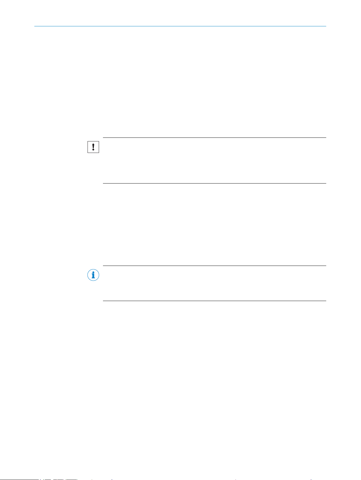
WARNING
Risk of injury and damage caused by potential equalization currents!
Improper grounding can lead to dangerous equipotential bonding currents, which may
in turn lead to dangerous voltages on metallic surfaces, such as the housing. Electrical
voltage can cause severe injury or death.
■
Work on electrical systems must only be performed by qualified electricians.
■
Follow the notes in the operating instructions.
■
Install the grounding for the product and the system in accordance with national
and regional regulations.
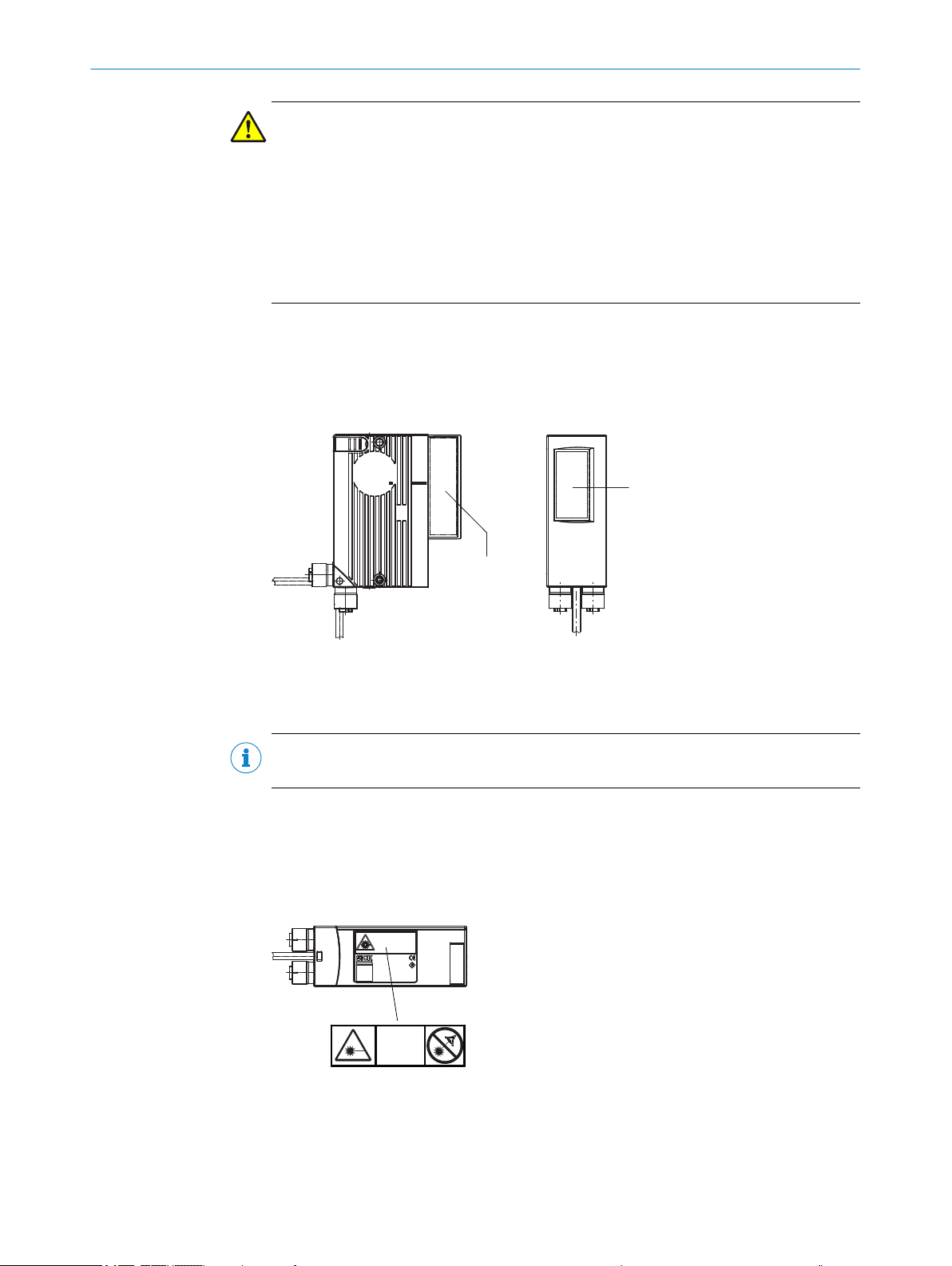
Additional information about laser radiation
The device uses a red light laser diode.
The entire reading window is a laser output aperture.
Figure 1: Laser output aperture in the housing
Laser output on side
1
Laser output on front
2
NOTE
No maintenance is required to ensure compliance with Laser Class 2.
Warning symbol on the device
The laser warning label is affixed on the rear of the device in combination with the type
label.
In addition to other information, the type label also contains the relevant laser output
data.
Figure 2: Laser warning label
Meaning of the laser warning label:
Laser radiation – Never look into the light beam – Laser Class 2
8017842/ZOK7/2019-02-01 | SICK OP E RA T IN G I N ST R UC T IO N S | CLV61x DualPort (PROFINET)
Subject to change without notice
11
Page 12

2 SAFETY INFORMATION
NOTE
Additional laser warning label
If the laser warning label affixed to the device is concealed when the device is installed
into a machine or paneling, the laser beam outlet opening must be suitably labeled on
the machine. For this purpose, an additional warning label must be affixed next to the
output opening.
Controlling the laser diode
When operating properly in real conditions, the device will only switch the laser diode on
if there is an object in the reading area, or if a reading is required (pulsed reading oper‐
ation). This operating mode results in a longer laser diode service life than with a laser
diode that is switched on in continuous operation.
A laser timeout can switch off the laser diode automatically in this type of object trigger
control if the pulse has been active for too long (e.g., the conveyor system has
stopped). In this case, the current internal reading interval of the device remains open.
Depending on the selected parameterization type, the laser timeout can be set as fol‐
lows:
•
•
In the default setting, the laser timeout is deactivated.
Using the SOPAS ET configuration software, on the Illumination Control device page.
With GSD parameterization, using the “10_Object Trigger Ctrl” module.
The laser diode is permanently or repeatedly switched on in the following device sta‐
tuses:
■
In the “Percentage Evaluation” and “Auto Setup” operating modes (only used tem‐
porarily for configuration/diagnostics)
■
In reading operation in the pulsing types “Auto pulse” (adjustable pulse/pause
ratio) or “Free”.
If the timeout is activated, it will have no effect in this case.
NOTE
The device has no optical indicator (LED) for laser diode activity.
2.8 Switching off the device
When switching off the device, at the most, the following data will be lost:
■
Application-specific parameter sets that were only temporarily stored in the device
■
Last reading result
■
Daily operating hours counter
2.9 Protection of the environment
During construction of the device, attention was paid to achieving the smallest environ‐
mental impact possible. Apart from the housing, the device contains no materials using
silicon.
2.10 Repairs
12
O PE R AT I NG IN S TR U CT I ON S | CLV61x DualPort (PROFINET) 8017842/ZOK7/2019-02-01 | SICK
Repair work on the device may only be performed by qualified and authorized person‐
nel from SICK AG. Interruptions or modifications to the device by the customer will inval‐
idate any warranty claims against SICK AG.
Subject to change without notice
Page 13
3 Product description
1240 0001
S/N:
DC 10...30V 2.8W
1
2
3
4
5
Manufactured:
D-79276 Reute
Made in Germany
λ = 655nm
Pmax=1.5mW
P<1.0mW average
Pulse duration <300µs
Imax=700mA
P/N: 1057125
CLV610-C000
MAC
6
25
3.1 Product ID
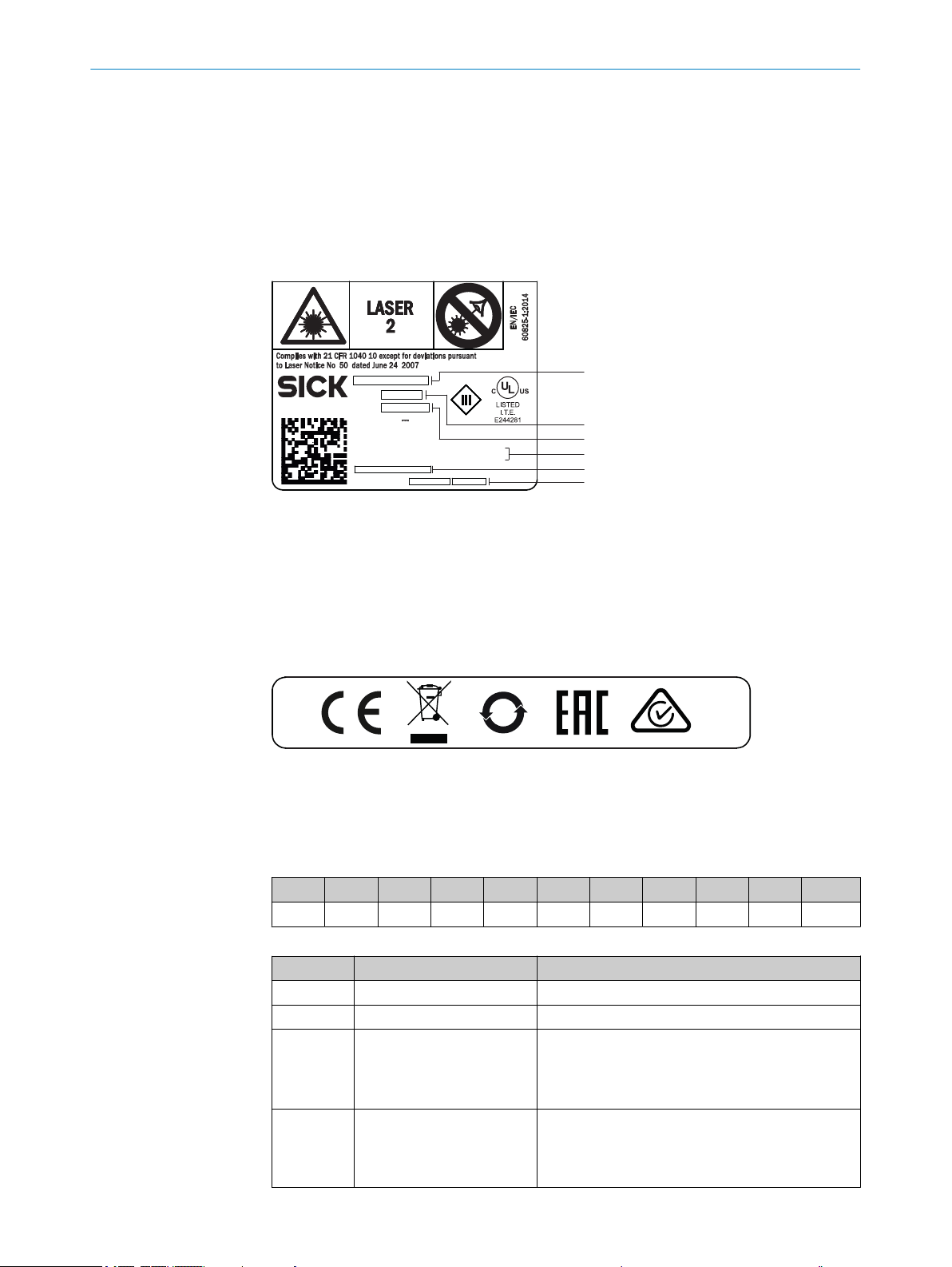
3.1.1 Type label
The type label gives information for identification of the device. An existing UL certifica‐
tion can be found on the type label.
Figure 3: Type label design for the device, illustration may differ from actual type label
Type designation
1
Part number
2
Serial number
3
Laser output data
4
MAC address, if Ethernet interface is available
5
Date of manufacture
6
PRODUCT DESCRIPTION 3
3.1.2 Type code
The devices of the CLV61x product subfamily are classified according to the following
type code:
CLVxyz-abcdef
CLV x y z ‒ a b c d e f
1 2 3 4 5 6 7 8 9 10
Table 2: Type code
Position Description Characteristic
1 Code reader, V-principle ‒
2 – 3 Product family 61: CLV61x
4 Working range 0: Mid range
2: Short range
5: Long range
8: Long range
5 Performance C: CAN
8017842/ZOK7/2019-02-01 | SICK OP E RA T IN G I N ST R UC T IO N S | CLV61x DualPort (PROFINET)
Subject to change without notice
D: Dual Port PROFINET
F: Fieldbus (Dual Port) over external fieldbus mod‐
ule CDF600-2
13
Page 14
3 PRODUCT DESCRIPTION
Position Description Characteristic
6 Scanning method, reading
7 Electrical connections
8 Interfaces 0: Host (RS-232), AUX (RS-232), digital I/Os
9 Front screen material 0: Glass
10 Application (ambient tem‐
1)
2 x digital switching inputs and 2 x digital switching outputs.
2)
USB interface only for temporary use as a service interface.
3)
For service functions such as parameter cloning.
window orientation
(design)
perature)
1)
0: Line scanner, reading window on front
1: Raster scanner, reading window on front
2: Line scanner, reading window on side
3: Raster scanner, reading window on side
0: Cable 0.9 m with male connector, D-Sub-HD,
15-pin
4: Swivel connector, 2 x female connectors, M12,
4-pin, D-coded +1 x cable 0.9 m with male connec‐
tor, M12, 4-pin, A-coded
5: Swivel connector, 2 x female connectors, M12,
4-pin, D-coded +1 x cable 0.9 m with male connec‐
tor, M12, 5-pin, A-coded
1)
1: Host (Ethernet), AUX (Ethernet, USB 2))
2: Host (Ethernet), AUX (Ethernet, USB 2)), 1 x digital
switching input
3: Host (Ethernet), AUX (Ethernet), 1 x external para‐
meter storage (microSD memory card)
3)
4: Host (Ethernet), AUX (Ethernet), 1 x external para‐
meter storage (microSD memory card) 3), 1 x digital
switching input
1: Plastic
Without label: Standard (0 °C ... +40 °C)
F0: With integrated heating (‒35 °C ... +40 °C)
NOTE
Not all combinations are possible according to the type code. The available device vari‐
ants can be found online at:
3.1.3 Device variants
The CLV61x product family consists of 3 variant lines:
Among other things, the variant lines differ with respect to the following features:
Table 3: Differences between the variant lines
www.sick.com/CLV61x_Dual_Port
•
CLV61x CAN
•
CLV61x FIELDBUS (in combination with the optional fieldbus module CDF600)
•
CLV61x Dual Port
•
Feature CLV61x CAN CLV61x FIELDBUS CLV61x Dual Port
(PROFINET)
Purpose Data output to host via
RS-232
Connection to fieldbus
via optional fieldbus
Direct integration in
line or ring topology
module CDF600
(Dual Port switch)
14
O PE R AT I NG IN S TR U CT I ON S | CLV61x DualPort (PROFINET) 8017842/ZOK7/2019-02-01 | SICK
Subject to change without notice
Page 15
PRODUCT DESCRIPTION 3
Feature CLV61x CAN CLV61x FIELDBUS CLV61x Dual Port
(PROFINET)
Electrical Interfaces
Type of electrical
connections
Power
•
RS-232
•
(Host, AUX)
CAN
•
2 digital switching
•
inputs
2 digital switching
•
outputs
Power
•
RS-232
•
(Host, AUX)
CAN
•
2 digital switching
•
inputs
2 digital switching
•
outputs
Power
•
Ethernet
•
(Host, AUX)
USB Micro-B or
•
microSD memory card
1) 2) 5)
1 digital switching
•
input
1)
1 x male connector, D-Sub-HD, 15-pin 2 x female connectors,
M12, 4-pin, D-coded in
swivel connector
1 x male connector, 4-
or 5-pin, A-coded
1 x female connector,
5-pin, USB Micro-B type
or
microSD memory card
1)
1)
Supply voltage DC 10 V ... 30 V DC 10 ... 30 V
DC 18 ... 30 V
Power consumption Typically 2.8 W
4)
Typically 4 W
Typically 15 W 3)
Special evaluation
SMART620 decoder
feature
Memory card – Optional 1)
Heating – Optional
Ambient operating
temperature
Storage tempera‐
ture
Dimensions for
device with front
0 °C ... +40 °C 0 °C ... +40 °C
–35 °C ... +40 °C 1)
–20 °C ... +70 °C –20 °C ... +70 °C
–35 °C ... +70 °C 1)
61 mm x 66 mm x 38 mm 61 mm x 96 mm x
38 mm
1)
reading window
Dimensions for
device with side
80 mm x 66 mm x 38 mm 80 mm x 96 mm x
38 mm
reading window
1)
Depending on type.
2)
USB interface only for temporary use as a service interface.
3)
For device variants with integrated heating.
4)
For switching outputs without load.
5)
USB interface or memory card shaft.
3)
4)
4)
5)
3)
3)
Designation of device variants
Device variants with serial data interfaces only (RS-232, RS422/485) are referred
•
to as “serial variants”. They also feature a CAN interface. The connecting cable
with a D-Sub male connector is permanently connected to the housing.
Device variants with serial data interfaces and two additional Ethernet interfaces
•
are referred to as “Dual Port variants”. They feature a swivel connector on the
housing with two M12 female connectors and a separate connecting cable with an
M12 male connector.
The corresponding number of digital switching inputs and outputs depends on the
•
design of the electrical connection.
8017842/ZOK7/2019-02-01 | SICK OP E RA T IN G I N ST R UC T IO N S | CLV61x DualPort (PROFINET)
Subject to change without notice
15
Page 16
1
42
ã
â
á
ß
65.3 (2.57)
38 (1.50)
Ready
G Read
N Read
HW Err
UserDef1
SF
BF
P1 LNK/ACT
P2 LNK/ACT
P1 P2
50°
61 (2.40)
96 (3.78)
(15
(0.59))
1
2
3
4
41.7
(1.64)
6.2 (0.24)
19.5 (0.77)
43.7
(1.72)
5
3
85 (3.35)
9 (0.35)
22
(0.87)
35.3
(1.39)
(25.7
(1.01))
65.3
(2.57)
(30.6
(1.20))
10 (0.39)
5.7 (0.22)
13.7 (0.54)
19.5 (0.77)
1
423
5
6
7
8
9
à
(15
(0.59))
15
(0.59)
(15
(0.59))
10 (0.39)
5.7 (0.22)
22.5
(0.89)
22.5
(0.89)
3 PRODUCT DESCRIPTION
3.2 Product characteristics
3.2.1 Device view
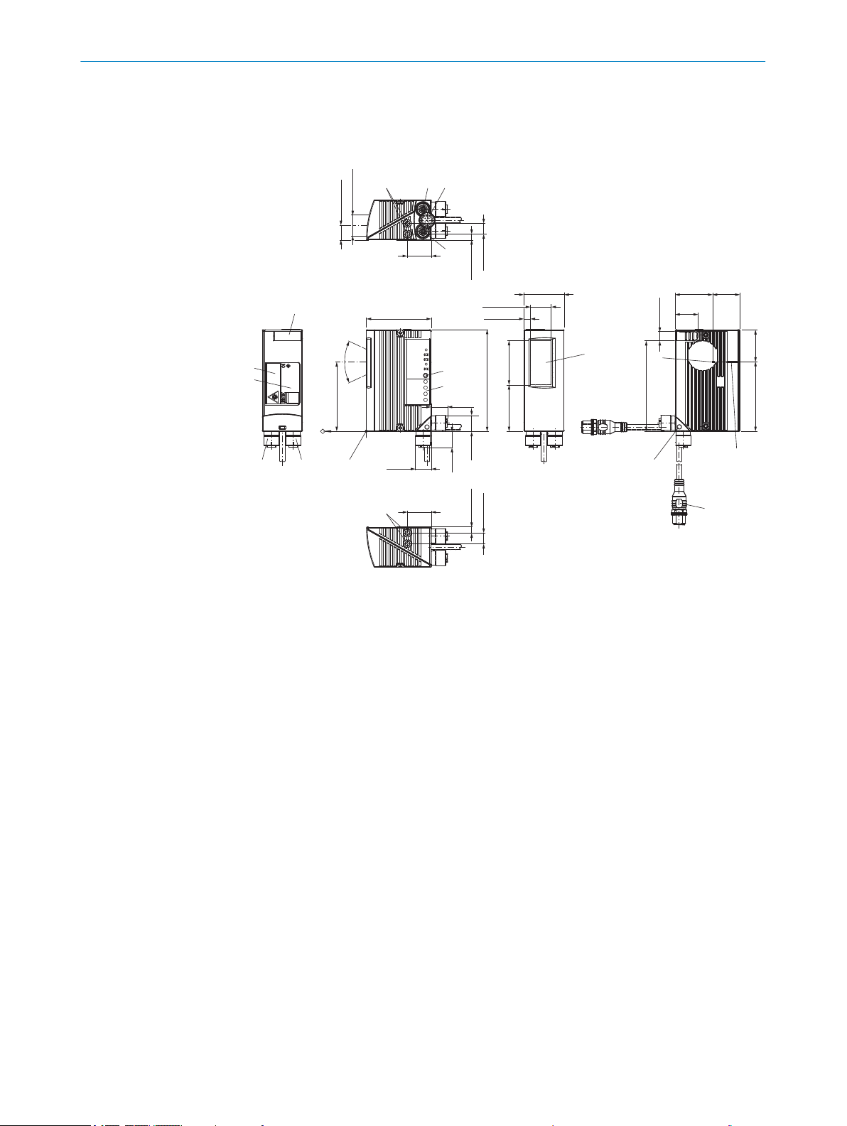
Figure 4: CLV61x Dual Port: design and device dimensions with front reading window (in mm or
inches)
M5 blind tapped holes, 5 mm deep (2 x), for mounting the device
1
P1 (PROFINET port 1) connection, female connector, M12, 4-pin, D-coded
2
Cable (0.9 m), type-dependent with POWER connection (male connector, M12, 4-pin, A-
3
coded) or with POWER + trigger input connection (male connector, M12, 5-pin, A-coded)
P2 (PROFINET port 2) connection, M12, female connector, 4-pin, D-coded
4
Internal impact point: Rotation point of the variable direction laser beam
5
Central position of the deflected laser beam in the V-shaped aperture angle
6
Swivel connector unit (max 180° rotation angle from end position to end position)
7
Reading window, orientation on front
8
RGB LED (1 x), status indicator with signal color allocation for events
9
LED (4 x), status indicator for PROFINET
ß
Reference point for reading distance from device (housing edge) to object
à
Type label
á
Laser warning label
â
Cover for USB connection 1) (female connector, 4-pin, Micro-B type) or for memory card
ã
shaft (microSD), type-dependent
1)
16
Service interface, for temporary use only
O PE R AT I NG IN S TR U CT I ON S | CLV61x DualPort (PROFINET) 8017842/ZOK7/2019-02-01 | SICK
Subject to change without notice
Page 17
15
(0.59)
10
(0.39)
22.5
(0.89)
2 (0.08)
5.7 (0.22)
105°
80 (3.15)
96 (3.78)
65 (2.56)
59.5 (2.34)
(15
(0.59))
(14.15
(0.56))
65.2 (2.57)
50°
38 (1.5)
60.4 (2.38)
16.4
(0.65)
35.3
(1.39)
(24.1
(0.95))
9 (0.35)85 (3.35)
(30.6 (1.2))
60.5 (2.38)
32.8
(1.29)
65.3 (2.57)
Ready
G Read
N Read
HW Err
UserDef1
SF
BF
P1 LNK/ACT
P2 LNK/ACT
1
4
2
3
1
2
3
4
6
5
7
3
1
P1
P2
42
8
ã
â
á
à
ß
9
10
(0.39)
5.7
(0.22)
22.5
(0.89)
10 (0.39)
(14.15
(0.56))
(15
(0.59))
PRODUCT DESCRIPTION 3
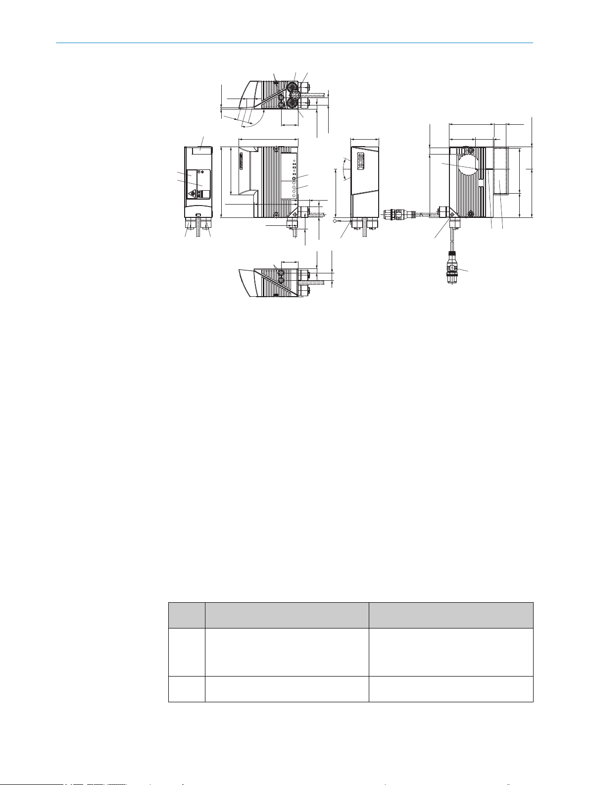
Figure 5: CLV61x Dual Port: design and device dimensions with side reading window (in mm or
inches)
M5 blind tapped holes, 5 mm deep (2 x), for mounting the device
1
P1 (PROFINET port 1) connection, female connector, M12, 4-pin, D-coded
2
Cable (0.9 m), type-dependent with POWER connection (male connector, M12, 4-pin, A-
3
coded) or with POWER + trigger input connection (male connector, M12, 5-pin, A-coded)
P2 (PROFINET port 2) connection, M12, female connector, 4-pin, D-coded
4
Internal impact point: Rotation point of the variable direction laser beam
5
Reading window, side orientation
6
Central position of the deflected laser beam in the V-shaped aperture angle
7
Swivel connector unit (max 180° rotation angle from end position to end position)
8
Reference point for reading distance from device (housing edge) to object
9
LED (4 x), status indicator for PROFINET
ß
RGB LED (1 x), status indicator with signal color allocation for events
à
Type label
á
Laser warning label
â
Cover for USB connection 2) (female connector, 4-pin, Micro-B type) or for memory card
ã
shaft (microSD), type-dependent
3.2.2 Scope of delivery
2)
8017842/ZOK7/2019-02-01 | SICK OP E RA T IN G I N ST R UC T IO N S | CLV61x DualPort (PROFINET)
Subject to change without notice
The delivery of the device includes the following components:
Table 4: CLV61x Dual Port (PROFINET): scope of delivery
No. of
units
1 Device in the version ordered Both M12 female connectors sealed with
Service interface, for temporary use only
1 Multilingual safety notes in a printed doc‐
Associated components not contained in the delivery:
Component Notes
tightly screwed on protective plugs.
Without holders and bus connecting
cables.
Provides information about the require‐
ument
ments for safe use of the product.
17
Page 18

3 PRODUCT DESCRIPTION
Table 5: CLV61x Dual Port (PROFINET): scope of delivery, other components
Component Notes
SOPAS ET configuration software and
device description file (*.sdd file for
SOPAS ET) for the CLV61x Dual Port
(PROFINET)
GSD file for the PROFINET system con‐
troller (PLC)
Function block, e.g., for system controller
S7 (PLC)
CLV61x Dual Port (PROFINET) operating
instructions as PDF in English, German
and French. Other languages also avail‐
able online where applicable.
CLV61x Dual Port (PROFINET) supplemen‐
tary information as PDF in English and
German.
Available online at:
www.sick.com/SOPAS_ET
•
Available online at:
www.sick.com/CLV61x_Dual_Port
•
When is it needed?
Available online at:
www.sick.com/CLV61x_Dual_Port
•
Provides information about mounting, electrical
installation and technical data for the device.
Available online at:
www.sick.com/CLV61x_Dual_Port
•
Provides additional description of the procedure for
integrating the device into PROFINET from a data
technology standpoint (line or ring topology).
Available online at:
www.sick.com/CLV61x_Dual_Port
•
3.2.3 Operating principle
The device consists of a laser scanner (laser diode and optics) with fixed focus and an
electronics unit with integrated decoder, as well as a PROFINET module. The laser scan‐
ner and electronic unit are encased in a compact metal housing.
The light is emitted through the reading window in the industrial housing, and the
reflected light from the bar code then returns through this window.
The use of various focusing settings, resolutions, scan processes, possibly integrated
heating, mounting options and optics enables use in most industrial applications.
Because of the integrated D-sub shell, when the reading window is on the side the laser
beam is emitted at angle of 105° relative to the longitudinal axis of the device. The
device has three M12 round connectors available for continuous electrical connection.
Interfaces to external timers, such as photoelectric sensors or incremental encoders,
enable reading pulses independent of the control. The reading results are provided for
further processing by the data interfaces. In principle, the codes can be identified on
any one side of stationary or moving objects in a conveyor system (single-side reading).
By combining several devices, multiple sides can be recorded in one passage (multiside reading). The device produces a scanning line (line scanner) in order to identify the
code. In the grid scanner version, the device produces eight scanning lines that are off‐
set parallel to one another.
18
O PE R AT I NG IN S TR U CT I ON S | CLV61x DualPort (PROFINET) 8017842/ZOK7/2019-02-01 | SICK
Subject to change without notice
Page 19
Configuration
Diagnostics
(local)
SOPAS ETSOPAS ET
PC
CLV61x Dual Port
(CLV61x-Dx41x)
Aux (USB)
Host /Aux (Ethernet, port 2)Host /Aux (Ethernet, port 1)
V
s
PROFINETPROFINET
Scanner 2
Decoder 3
Interfaces 4
5
1
Configuration
1)
Diagnostics
(local)
SOPAS ETSOPAS ET
PC
CLV61x Dual Port
(CLV61x-Dx52x)
Aux (USB)
Host /Aux (Ethernet, port 2)Host /Aux (Ethernet, port 1)
V
s
PROFINETPROFINET
Read trigger
(switching input) 1
Scanner 2
Decoder 3
Interfaces 4
T distributor 2) 6
1) Alternative: GSD configuration (centrally via the PROFINET controller) 8
2) Male connector, M12, 4-pin, A-coded splitted to 2 x female connector M12, 5-pin, A-coded) 9
5
7
PRODUCT DESCRIPTION 3
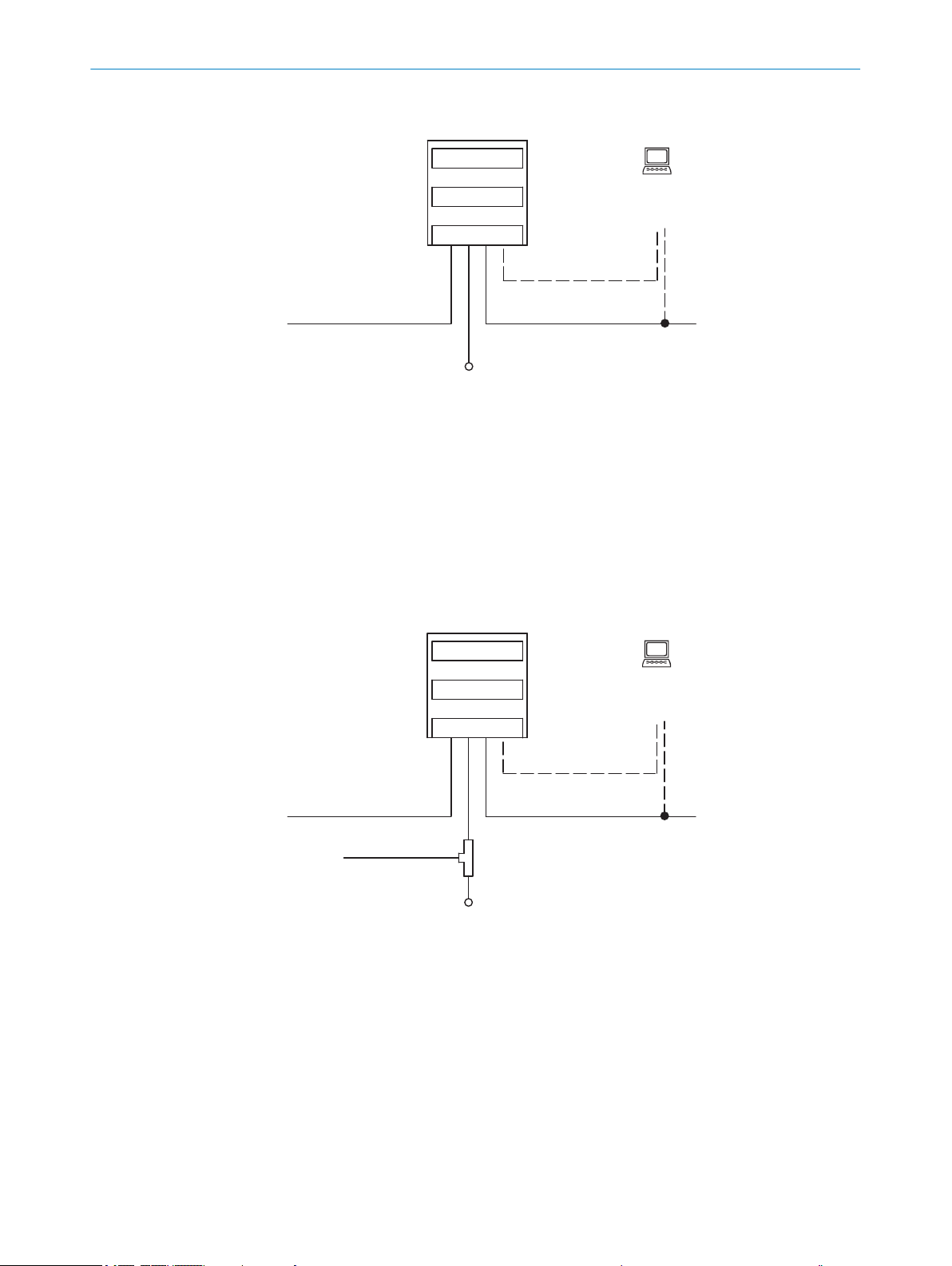
Figure 6: Block diagram for CLV61x-Dx41x (without switching input)
Scanner
1
Decoder
2
Interfaces
3
USB interface 3) depending on type. Not present on device variants with a memory card
4
slot.
Configuration or diagnostics (local)
5
Supply voltage VS = U
6
V
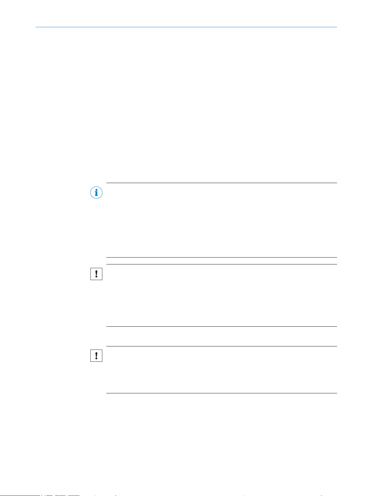
Figure 7: Block diagram for CLV61x-Dx52x (with switching input)
1
2
3
4
5
6
7
3)
Service interface, for temporary use only
8017842/ZOK7/2019-02-01 | SICK OP E RA T IN G I N ST R UC T IO N S | CLV61x DualPort (PROFINET)
Subject to change without notice
Scanner
Decoder
Interfaces
USB interface 3) depending on type. Not present on device variants with a memory card
slot.
Configuration or diagnostics (local)
T-connector
Supply voltage V
s
19
Page 20

3 PRODUCT DESCRIPTION
Read trigger (switching input)
8
Alternative: GSD configuration (central via PROFINET controller)
9
Male connector, M12, 4-pin, A-coded, split into 2 x female connectors, M12, 5-pin, A-
ß
coded
3.2.4 Product features and functions
Table 6: Overview of product features and functions of the device
Product feature/function Characteristic
CLV61x Dual Port bar code scanner
Safety and ease of use
Easy configuration/operation
Reading Operation Mode
Read pulse generation
Bar code evaluation
Data Processing
Fixed focus
■
Red light line scanner or grid scanner
■
Reading range: Long range, optimized for intralogistics applications
■
Medium resolution
■
Additional scanning frequency range (400 Hz ... 1,000 Hz)
■
Option to adapt to code print quality
■
Evaluation range of scanning line can be limited
■
Trigger input for reading pulse, type-dependent, identifier see "Type code",
■
page 13
Rugged, compact metal housing, CE marking
■
Laser Class 2, laser switches off if the output power is exceeded
■
Automatic self-test on system start
■
Diagnostic tools for device setup and (remote) device monitoring
■
Configurable output of reading diagnostic data in two reading results formats
■
Operating data polling, in case of error, issue of error code if required
■
Test string function (heartbeat) can be activated to signal that the device is
■
ready for operation
Password-protected configuration mode via SOPAS ET
■
Protection of centrally configured parameter values in the PROFINET con‐
■
troller (e.g., PLC) via GSD parameterization
Optional backup of locally configured parameter values on microSD memory
■
card in the device, type-dependent, identifier see "Type code", page 13
Future-proof through firmware update (FLASH PROM) via data interface
■
Future-proof SOPAS ET configuration software
■
Low power consumption
■
Additional supply voltage range
■
Wide range of ambient operating temperatures
■
Device variants suitable for cold stores, type-dependent, identifier see "Type
■
code", page 13)
Configuration centrally using PROFINET controller (e.g., PLC) via GSD parame‐
■
terization or locally via SOPAS ET configuration software (incl. online help
function)
Status display by five LEDs
■
Configuration via profile programming with bar codes, generated and printed
■
with the help of SOPAS ET
Start/stop operation (one bar-code bearing object per reading pulse)
■
Pulse source for start: Fieldbus input, data interface (command), auto pulse,
■
free
Pulse source for stop: Read pulse source, data interface (command), timer,
■
condition
All current 1D code types
■
Max. number of bar codes: 50 per read pulse
■
Separation of identical codes of the same code type by read angle
■
Influencing the output of the reading data by event-dependent evaluation con‐
■
ditions
Influencing the output string by filtering and output sorting
■
20
O PE R AT I NG IN S TR U CT I ON S | CLV61x DualPort (PROFINET) 8017842/ZOK7/2019-02-01 | SICK
Subject to change without notice
Page 21

Product feature/function Characteristic
Data communication
Host interface: Ethernet, PROFINET protocol, data output format can be con‐
■
figured
AUX interface: USB (2.0) 1). Type-dependent, identifier see "Type code",
■
page 13. Data output format configurable
Aux interface: Ethernet TCP/IP, data output format configurable
■
PROFINET
PROFINET with integrated switch (Dual Port) in accordance with IEEE 802.3
■
for incorporation in line or ring network topologies
Local trigger input (hardware) for reading pulse, type-dependent, identifier
■
see "Type code", page 13
Electrical interfaces
Host interface (also AUX interface): 2 x Ethernet
■
Aux interface: 1 x USB 1), type-dependent, identifier see "Type code", page 13
■
MicroSD memory card, type-dependent, identifier see "Type code", page 13
■
Digital switching input (hardware): 1 x, type-dependent, identifier see "Type
■
code", page 13
Power supply
■
Wiring technique (design)
Space-saving, swivel connector on the device with two M12 round connec‐
■
tors, female connector, 4-pin, D-coded for Ethernet (PROFINET)
Cable (0.9 m), line connection integrated into the control unit.
■
Type-dependent in the following forms:
With POWER connection (male connector, M12, 4-pin, A-coded), type-
°
dependent, identifier see "Type code", page 13
With POWER connection + trigger input (male connector, M12, 5-pin, A-
°
coded), identifier see "Type code", page 13
Housing
Compact, industrial version in metal, IP 65, protection class III
■
Small dimensions, low weight
■
Various installation options via comprehensive range of mounting accessories
■
PRODUCT DESCRIPTION 3
1)
Service interface, for temporary use only
3.2.5 Memory card
Depending on the type, the device has a card slot integrated in the housing. This slot
accommodates a memory card in microSD format.
NOTE
The memory card is optional and is not included with the delivery of the device.
To ensure that the memory card functions reliably, only use card types (industrial stan‐
dard) approved by SICK. You can find these as accessories online at:
The memory card has no write protection that can be activated.
Functions
An inserted memory card serves as a local external storage medium for the device out‐
side the internal device memory, see "Initial commissioning", page 43.
The device can execute the following functions using the memory card:
www.sick.com/CLV61x_Dual_Port
•
Cloning function: saving the currently valid parameter set
•
Automated additional storage of the parameter set with the configuration data of
the device on an external storage medium that is quickly accessible to the user.
This takes place as part of the recommended backup concept for the parameter
sets of the 4Dpro devices. The externally stored parameter set is also updated
automatically each time the currently valid configuration data is permanently
saved.
8017842/ZOK7/2019-02-01 | SICK OP E RA T IN G I N ST R UC T IO N S | CLV61x DualPort (PROFINET)
Subject to change without notice
21
Page 22
3 PRODUCT DESCRIPTION
•
The first time a parameter set is stored, we recommend using an empty memory card.
b
Device access to the memory card
NOTE
The device does not directly signal access (read, write) to the memory card.
By observing the sensor LED, it is possible to tell when the storage process has been
completed when the parameter set is saved with the “permanent” option:
The cloning function serves as a basis for performing the following tasks, for
°
example:
Manually transferring an identical parameter set to multiple devices of
•
the same type on the PROFINET network (cloning). The PN name of each
device must be adjusted in coordination with the PROFINET controller.
In the event of a device fault, a convenient and rapid manual transfer of
•
the currently valid parameter set to an exchange unit of the same type in
the read station.
Automated saving to the external storage medium is triggered by saving the para‐
meter set in the device with the “permanent” option, e.g., via the SOPAS ET config‐
uration software.
Other functions available on request.
If necessary, check and delete the contents of your current card on the PC using a
card reader.
When the device starts saving, the sensor LED in the “Device Ready” indicator
•
function goes out.
When the device has finished saving, the sensor LED in the “Device Ready” indica‐
•
tor function LED lights up blue again.
NOTICE
Possible data loss!
Do not remove the memory card or switch off the supply voltage as long as the
b
following initiated operations are still being executed on the device using the
SOPAS ET configuration software:
■
Permanent change to the parameter set by saving with the “permanent”
option.
Inserting the memory card in the device:
NOTICE
Risk of damage to the memory card!
To avoid damaging the memory card, make sure the device is de-energized when
b
you insert or remove the card. For this purpose, disconnect the device from the
supply voltage accordingly.
Access to the card slot
22
The card slot for the memory card is located beneath the black rubber cover fitted at
the side over the corner on the device.
O PE R AT I NG IN S TR U CT I ON S | CLV61x DualPort (PROFINET) 8017842/ZOK7/2019-02-01 | SICK
Subject to change without notice
Page 23

1 2
PRODUCT DESCRIPTION 3
Figure 8: Slot for microSD memory card (only CLV61x-DxxXxx, with x = 3 oder 4), illustration may
differ
Open cover on the device
1
MicroSD memory card
2
1. Switch off the supply voltage to the device.
2. Open the black rubber cover.
To do so, carefully lift the flap of the rubber cover.
3. Making sure it is in the correct position, insert the memory card into the slot until
it locks into place. When doing this, position the contacts so that they are facing to
the rear and upwards, see the card symbol on the device.
4. Close the rubber cover. Make sure that the cover is completely flush with the hous‐
ing.
5. Switch on the supply voltage for the device.
Interpretation of the stored parameter set
Once it is switched on, the device automatically detects the presence of a memory card
and, depending on the card’s content, behaves as follows:
■
If the card is empty or if it contains a parameter set that cannot be interpreted by
the device, the device saves the currently valid internal parameter set to the card
(provided there is sufficient storage space). The device then starts with the inter‐
nal parameter set.
■
If the card contains a parameter set that can be interpreted by the device, the
device permanently overwrites the currently valid internal parameter set with this
external parameter set. The device then starts with the new valid parameter set.
■
The goal is for the internal parameter set and the parameter set saved externally
to always be identical.
The highest-ranking parameter set is used by the device when operated in the
PROFINET with the following sequence hierarchy:
8017842/ZOK7/2019-02-01 | SICK OP E RA T IN G I N ST R UC T IO N S | CLV61x DualPort (PROFINET)
Subject to change without notice
23
Page 24
3 PRODUCT DESCRIPTION
1 After starting, the device loads the last permanently stored internal parameter set
2 The device then searches for a valid parameter set in the optional memory card
3 If the PROFINET controller sends a parameter set via the PROFINET with central
Removing the memory card from the device:
NOTICE
Risk of damage to the memory card!
b
1. Switch off the supply voltage to the device.
2. Open the black rubber cover.
3. Unlock the memory card in the slot and remove it.
4. Close the rubber cover. Make sure that the cover is completely flush with the hous‐
5. Switch on the supply voltage for the device.
to its working memory.
slot. If there is a positive search result, the device uses this parameter set to over‐
write the existing parameter set in its working memory.
configuration of the bus users, the device again overwrites corresponding parame‐
ter values in its working memory. These changes are lost again when the device is
switched off. The PROFINET controller must then again send the most recently
valid parameter values each time the device is restarted (supply voltage is
switched on).
To avoid damaging the memory card, make sure the device is de-energized when
you insert or remove the card. For this purpose, disconnect the device from the
supply voltage accordingly.
To do so, carefully lift the flap of the rubber cover.
To do so, carefully press down once on the memory card.
ing.
Support Portal
NOTE
In the SICK Support Portal (supportportal.sick.com, registration required) you will find,
besides useful service and support information for your product, further detailed infor‐
mation on the available accessories and their use.
24
O PE R AT I NG IN S TR U CT I ON S | CLV61x DualPort (PROFINET) 8017842/ZOK7/2019-02-01 | SICK
Subject to change without notice
Page 25

4 Transport and storage
4.1 Transport
For your own safety, please read and observe the following notes:
NOTICE
Damage to the product due to improper transport.
■
The device must be packaged for transport with protection against shock and
damp.
■
Recommendation: Use the original packaging as it provides the best protection.
■
Transport should be performed by trained specialist staff only.
■
The utmost care and attention is required at all times during unloading and trans‐
portation on company premises.
■
Note the symbols on the packaging.
■
Do not remove packaging until immediately before you start mounting.
TRANSPORT AND STORAGE 4
4.2
Transport inspection
4.3 Storage
Immediately upon receipt in Goods-in, check the delivery for completeness and for any
damage that may have occurred in transit. In the case of transit damage that is visible
externally, proceed as follows:
■
Do not accept the delivery or only do so conditionally.
■
Note the scope of damage on the transport documents or on the transport com‐
pany's delivery note.
■
File a complaint.
NOTE
Complaints regarding defects should be filed as soon as these are detected. Damage
claims are only valid before the applicable complaint deadlines.
Store the device under the following conditions:
■
Recommendation: Use the original packaging.
■
Electrical connections are provided with protective caps and plugs (as they are on
delivery).
■
Do not store outdoors.
■
Store in a dry area that is protected from dust.
■
So that any residual damp can evaporate, do not package in airtight containers.
■
Do not expose to any aggressive substances.
■
Protect from sunlight.
■
Avoid mechanical shocks.
■
Storage temperature: see "Technical data", page 55.
■
Relative humidity: see "Technical data", page 55.
■
For storage periods of longer than 3 months, check the general condition of all
components and packaging on a regular basis.
8017842/ZOK7/2019-02-01 | SICK OP E RA T IN G I N ST R UC T IO N S | CLV61x DualPort (PROFINET)
Subject to change without notice
25
Page 26

5 MOUNTING
5 Mounting
5.1 Overview of mounting procedure
Selecting and preparing the mounting location.
•
Mounting the device.
•
Align device towards object with bar code.
•
Connect device to data cable (PROFINET) and supply cable.
•
Adjust the device.
•
WARNING
Risk of injury due to damage to the device
For reasons of safety, a device which is visibly damaged must not be operated or must
be immediately taken out of operation. Damage includes, for example:
Housing: Cracked or broken
•
Reading window lens: Cracked or broken
•
Device with connector: Over-rotation of the connector, cracks, or being torn from
•
the housing
Device with fixed cable: Damage to the cable outlet or cable itself
•
5.2 Preparation for mounting
5.2.1 Mounting requirements
NOTICE
Radio interference may occur when the device is used in residential areas!
Only use the device in industrial environments (EN 61000-6-4).
Space requirements
■
Typical space requirement for device, see type-specific dimensional drawing and
reading field diagram.
■
The device requires a direct, unimpeded line of sight to the codes being read.
Environmental influences
■
Comply with technical data, such as the permitted ambient conditions for opera‐
tion of the device (e.g., temperature range, EMC interference emissions, ground
potential), see "Technical data", page 55.
■
To prevent the formation of condensation, avoid exposing the device to rapid
changes in temperature.
■
Keep the device out of direct sunlight. The prevents additional external heating
and potential optical dazzle of the device.
Mounting
■
The device must only be mounted using the pairs of blind tapped holes provided
for this purpose.
■
Mount the device in a shock- and vibration-insulated manner.
26
Equipment required
■
Mounting device (bracket) with sufficient load-bearing capacity and suitable
dimensions for the device.
■
2 x M5 screws – the maximum screw-in depth in the device is 5 mm from the
housing surface
O PE R AT I NG IN S TR U CT I ON S | CLV61x DualPort (PROFINET) 8017842/ZOK7/2019-02-01 | SICK
Subject to change without notice
Page 27

MOUNTING 5
NOTE
The screws are for mounting the device on mounting equipment (bracket) supplied
by the user. The screw length depends on the mounting base (wall thickness of the
bracket). When using an optional SICK bracket, the screws for mounting the device
are included in the scope of delivery for the bracket.
■
Tool and tape measure
5.2.2 Instructions for mounting the device when the ambient temperature can fall below 0 °C
NOTE
For the electrical installation procedure, see "Instructions for electrical installation when
the ambient temperature can fall below 0 °C", page 33
The devices with integrated heating (CLV61x-DxxxxxF0) can be operated at low ambient
temperatures down to –35 °C.
Prerequisites:
Only perform mounting and connection work at ambient temperatures between
•
–25 °C and 40 °C.
The device may only be in a non-operating state at ambient temperatures below
•
0 °C.
During mounting, make sure that heat transfer between the device and the sur‐
•
rounding environment is kept as small as possible. Use appropriate holders
(optional accessories).
NOTICE
Operating the device at the lower limit of the permissible ambient temperature range
The ensure that the device can produce the required heating power, do not expose it to
strong air flows (e.g. from a ventilation system).
b
NOTICE
If the ambient temperature is below 0 °C, please note:
•
•
5.2.3 Mounting device
The device is mounted on the bracket using at least two M5 blind hole threads that are
in pairs on both of the narrow sides of the device, see "Device view", page 16.
The device can be installed using optional SICK brackets or customer-specific brackets.
SICK offers prefabricated brackets which are optimally suited for the mounting of the
device in a wide range of applications. See:
•
Example: The design of the bracket and adapter plate supports many different installa‐
tion variants, for example, as well as the alignment of the device on two axes.
If necessary, take appropriate measures to shield the device from air flows.
The black rubber cover fitted at the side over the corner must be flush with the
device.
Do not move the swivel connector on the device.
www.sick.com/CLV61x_Dual_Port
8017842/ZOK7/2019-02-01 | SICK OP E RA T IN G I N ST R UC T IO N S | CLV61x DualPort (PROFINET)
Subject to change without notice
27
Page 28

1
1
1
1
5 MOUNTING
Figure 9: Example mounting of a device with bow-shaped mounting bracket (SICK accessories,
illustration of the device can differ)
Devices with heating
NOTE
Three plastic insulation panes are to be used across from the bracket for heat insula‐
tion on devices with heating. These panes are included with the mounting brackets for
thermal decoupling (SICK accessories).
28
Figure 10: Example mountings of a device with external heating using bow-shaped mounting
brackets (SICK accessories). Illustration of the device may differ.
Plastic insulation panes
1
User-supplied brackets
The brackets should meet the following requirements:
■
Stable mounting device
O PE R AT I NG IN S TR U CT I ON S | CLV61x DualPort (PROFINET) 8017842/ZOK7/2019-02-01 | SICK
Subject to change without notice
Page 29

– Alignment of the device in the x and y axes can be adjusted.
line scanner raster scanner
1 2
– The mounting device must be able to bear the weight of the device and con‐
necting cables without shock.
– The housing must be thermally isolated from the bracket for devices with
heating. To do so, attach appropriate plastic insulating slabs to the fixing
screws between the housing and the bracket.
■
Two or three M5 screws for mounting the device
– The screw length depends on the wall thickness of the mounting device.
– The maximum screw in depth in the device is 5 mm from the housing sur‐
face.
5.3 Mounting location
When selecting the mounting location, the following factors are significant:
Basic allocation of the scan line to the bar code.
•
Reading distance to the bar code and aperture angle α
•
Angular alignment of the device
•
Avoidance of surface reflections
•
Count direction of the reading angle (position of the bar code along the scan line)
•
5.3.1 Basic allocation of the scan line to the bar code
MOUNTING 5
The basic allocation of the scan line to the bar code on the object depends on the ver‐
sion of the device (line scanner or grid scanner).
Figure 11: Allocation of scanning line(s) to bar code and conveyor direction
Line scanner
1
Grid scanner
2
5.3.2 Reading distance to the bar code and aperture angle α
The maximum distance from the reading window of the device to the bar code may not
exceed the design values for the device. Because of the V-shaped deflection of the
beams, the usable length of the scan line for evaluation (reading field height) depends
on the reading distance.
8017842/ZOK7/2019-02-01 | SICK OP E RA T IN G I N ST R UC T IO N S | CLV61x DualPort (PROFINET)
Subject to change without notice
29
Page 30

line scanner raster scanner
reading distance reading distance
1 2
3
3
β
α
γ
1
2
5 MOUNTING
Figure 12: Definition of the reading distance and the aperture angle α
Line scanner
1
Grid scanner
2
Reading distance
3
In the specification diagrams (see "Reading field diagrams", page 58), the height of
the reading field is shown as a function of the reading distance for differing resolutions
(module widths).
5.3.3 Angle alignment of the device
The optimum alignment of the device is achieved when the scan line crosses the
stripes of the bar code as close to a right angle as possible (tilt and inclination). Possi‐
ble reading angles that can arise between scan line and bar code at all three levels in
the area must be taken into account.
In order to prevent surface reflections, the angle of rotation must be approx. 15° out of
plumb to the bar code, see "Avoidance of surface reflections", page 31.
Figure 13: Line scanner: Read angle occurring between scanning line and bar code
Depth of field
1
Reading distance
2
NOTE
30
O PE R AT I NG IN S TR U CT I ON S | CLV61x DualPort (PROFINET) 8017842/ZOK7/2019-02-01 | SICK
The specified maximum values can only be reached in optimum conditions. The actual
maximum depends on module width, code type, print contrast, ambient light, distance
and scanning frequency.
Subject to change without notice
Page 31

Table 7: Permitted read angle between scanning line and bar code
Line scanner
(reading window on front)
Line scanner
(reading window on side)
(Top view)(Top view)
105° 105°
1 2
3
3
RA
0
100
Angle Limit Value
Tilt α Max. 30°
Pitch β Max. 45°
Skew γ Max. 45°
5.3.4 Avoidance of surface reflections
If the light of the scan line(s) hit(s) the surface of the bar code precisely vertically, this
may cause interference when the light reflected back is received. To prevent this effect,
the device must be mounted so that the light emitted is tilted relative to the vertical.
Figure 14: Avoiding surface reflections on the example line scanner: Angle between light emitted
and bar code (tilting away from vertical)
Line scanner (reading window on front)
1
Line scanner (reading window on side)
2
Supervision
3
MOUNTING
5
5.3.5 Count direction of the reading angle and the code angle
The device can scan and decode several bar codes at each reading.
At the same time, the location-specific reading diagnostics data are determined for
each of them.
■
The reading angle, starting from the reading window, at which the device detects
the bar code center on the red scanning line of the deflected scanning beam can
be outputted as an RA (reading angle) value.
By determining the respective RA value, identical bar codes (code type, code length,
and data content) can be separated, and the bar code data can be assigned based on
its position on the object.
Figure 15: Counting direction of the reading angle RA in the scanning line on devices with front
and side reading windows
8017842/ZOK7/2019-02-01 | SICK OP E RA T IN G I N ST R UC T IO N S | CLV61x DualPort (PROFINET)
Subject to change without notice
31
Page 32

MOUNTING
5
5.4 Mounting the device
NOTICE
Risk of damaging the device!
Observe the maximum screw-in depth of the blind hole thread. Longer screws than
specified damage the device.
Use screws of suitable length.
b
1. Prepare the base for mounting the bracket of the device, see "Preparation for
mounting", page 26.
2. Place the object with the bar code in the view of the device in the position where
the reading is to take place (conveyor static).
3. Align device with the bar code by eye. When doing so, be aware of the following:
– For a device with the reading window at the front, ensure that the rear side
– For a device with the reading window at the side, ensure that the side panel
– During reading, note the reading angle that occurs see "Angle alignment of
– If the position of the bar code within the scanning line is relevant for the eval‐
4. Mount the device bracket onto the base.
5. Screw screws through the bracket into the blind hole threads of the device and
slightly tighten.
6. Configure the device, see "Adjust the device", page 43.
with the laser warning label points in the direction of the observer and is
aligned as near as possible to being parallel to the bar code surface.
with the LEDs points in the direction of the observer and is aligned almost
parallel to the bar code surface.
the device", page 30.
uation, bear in mind the count direction of the code position see "Count direc‐
tion of the reading angle and the code angle", page 31.
32
O PE R AT I NG IN S TR U CT I ON S | CLV61x DualPort (PROFINET) 8017842/ZOK7/2019-02-01 | SICK
Subject to change without notice
Page 33

6 Electrical installation
6.1 Safety
6.1.1 Notes on the electrical installation
■
The electrical installation must only be performed by electrically qualified person‐
nel.
■
Standard safety requirements must be met when working on electrical systems.
■
Only switch on the supply voltage for the device when the connection tasks have
been completed and the wiring has been thoroughly checked.
■
When using extension cables with open ends, ensure that bare wire ends do not
come into contact with each other (risk of short-circuit when supply voltage is
switched on!). Wires must be appropriately insulated from each other.
■
Wire cross-sections in the supply cable from the customer's power system must be
selected in accordance with the applicable standards. When this is being done in
Germany, observe the following standards: DIN VDE 0100 (Part 430) and DIN VDE
0298 (Part 4) and/or DIN VDE 0891 (Part 1).
■
Circuits connected to the device must be designed as SELV circuits (SELV = Safety
Extra Low Voltage).
■
Protect the device with a separate fuse (type-specific max. 2 A (unheated) or 3 A
(heated)) at the start of the supply circuit.
ELECTRICAL INSTALLATION 6
NOTE
Layout of data cables
■
Use screened data cables with twisted-pair wires.
■
Implement the screening design correctly and completely.
■
To avoid interference, e.g. from switching power supplies, motors, clocked drives,
and contactors, always use cables and layouts that are suitable for EMC.
■
Do not lay cables over long distances in parallel with power supply cables and
motor cables in cable channels.
The specified IP enclosure rating for the device is only achieved under the following con‐
ditions:
■
The cables plugged into the connections are screwed tight.
■
Any electrical M12 connections that are not being used must be fitted with tightlyfastened protective caps or plugs (as in the delivery condition), depending on the
type.
■
Any other possible coverings must be closed and lie flush on the device.
In the event of non-compliance, the IP enclosure rating will not apply for the device.
6.1.2 Instructions for electrical installation when the ambient temperature can fall below 0 °C
NOTE
For mounting instructions, see "Instructions for mounting the device when the ambient
temperature can fall below 0 °C", page 27
The devices with integrated heating (CLV61x-DxxxxxF0) can be operated at low ambient
temperatures down to –35 °C.
8017842/ZOK7/2019-02-01 | SICK OP E RA T IN G I N ST R UC T IO N S | CLV61x DualPort (PROFINET)
Subject to change without notice
33
Page 34

6 ELECTRICAL INSTALLATION
Prerequisites:
Only perform mounting and connection work at ambient temperatures between
•
–25 °C and +40 °C.
The device may only be in a non-operating state at ambient temperatures below
•
0 °C.
Restricted supply voltage range: 18 V DC ... 30 V DC
•
Use cables suitable for the ambient conditions. For SICK standard cables for the
•
specified ambient temperature range, see:
°
When in doubt, please consult SICK Service.
Secure connecting cables.
•
On the device:
The cables plugged into the two electrical M12 female connectors must be
•
screwed on tightly.
Any electrical M12 female connector not in use at the end of a line must be sealed
•
with protective plugs that are screwed on tightly (as in the delivery condition).
The M12 male connector of the connecting cable must be tightly screwed to the
•
contacted female connector.
www.sick.com/CLV61x_Dual_Port
6.1.3 Behavior of the device with heating when switched on
After application of the supply voltage and successful initialization, the device can
immediately be addressed by the SOPAS ET configuration software.
The initialization time depends on the ambient conditions. Once the device has reached
a certain internal housing temperature, it enters the warm-up phase and the sensor
LED flashes magenta. The warm-up phase takes approx. 1 minute. After that, the sen‐
sor LED shows a steady blue light, and the device will have begun regular operation.
Once the supply voltage has been applied, the device uses integrated temperature sen‐
sors to measure its internal temperature. This is performed by the device while booting.
In addition, the device has an integrated heater that monitors its internal temperature
at regular intervals during operation. The device switches the heater off once it has
warmed up to +5 °C, and switches it back on if the internal temperature drops to
–15 °C. A circuit protection device prevents the heater from overheating.
6.1.4 Note on the swivel connector
NOTICE
Damage to the connector unit from over tightening!
The connector unit on the device has two opposite end positions.
■
Do not rotate the connector unit from either of the two end positions by more than
180°.
■
Always rotate the connector unit in the direction of the display LEDs.
34
O PE R AT I NG IN S TR U CT I ON S | CLV61x DualPort (PROFINET) 8017842/ZOK7/2019-02-01 | SICK
Subject to change without notice
Page 35

Figure 16: Swivel connector: rotation direction from end position to end position. Illustration may
differ from actual device.
6.2 Prerequisites for safe operation of the device
WARNING
Risk of injury and damage caused by electrical current!
As a result of equipotential bonding currents between the device and other grounded
devices in the system, faulty grounding of the device can give rise to the following dan‐
gers and faults:
■
Metal housings are vulnerable to dangerous currents.
■
Devices will behave incorrectly or be destroyed.
■
Cable shielding will be damaged by overheating and cause cable fires.
ELECTRICAL INSTALLATION 6
Remedial measures
■
Only skilled electricians should be permitted to carry out work on the electrical sys‐
tem.
■
If the cable insulation is damaged, disconnect the voltage supply immediately and
have the damage repaired.
■
Ensure that the ground potential is the same at all grounding points.
■
Where local conditions do not meet the requirements for a safe earthing method,
take appropriate measures (e.g., ensuring low-impedance and current-carrying
equipotential bonding).
The device is connected to the peripheral devices (voltage supply, any local trigger sen‐
sor(s), system controller) via shielded cables. The cable shield – for the data cable,
for example – rests against the metal housing of the device. The device can be
grounded through the cable shield or through a blind tapped hole in the housing,
for example.
If the peripheral devices have metal housings and the cable shields are also in contact
with their housings, it is assumed that all devices involved in the installation have the
same ground potential.
This is achieved by complying with the following conditions:
■
Mounting the devices on conductive metal surfaces
■
Correctly grounding the devices and metal surfaces in the system
■
If necessary: low-impedance and current-carrying equipotential bonding between
areas with different ground potentials
8017842/ZOK7/2019-02-01 | SICK OP E RA T IN G I N ST R UC T IO N S | CLV61x DualPort (PROFINET)
Subject to change without notice
35
Page 36
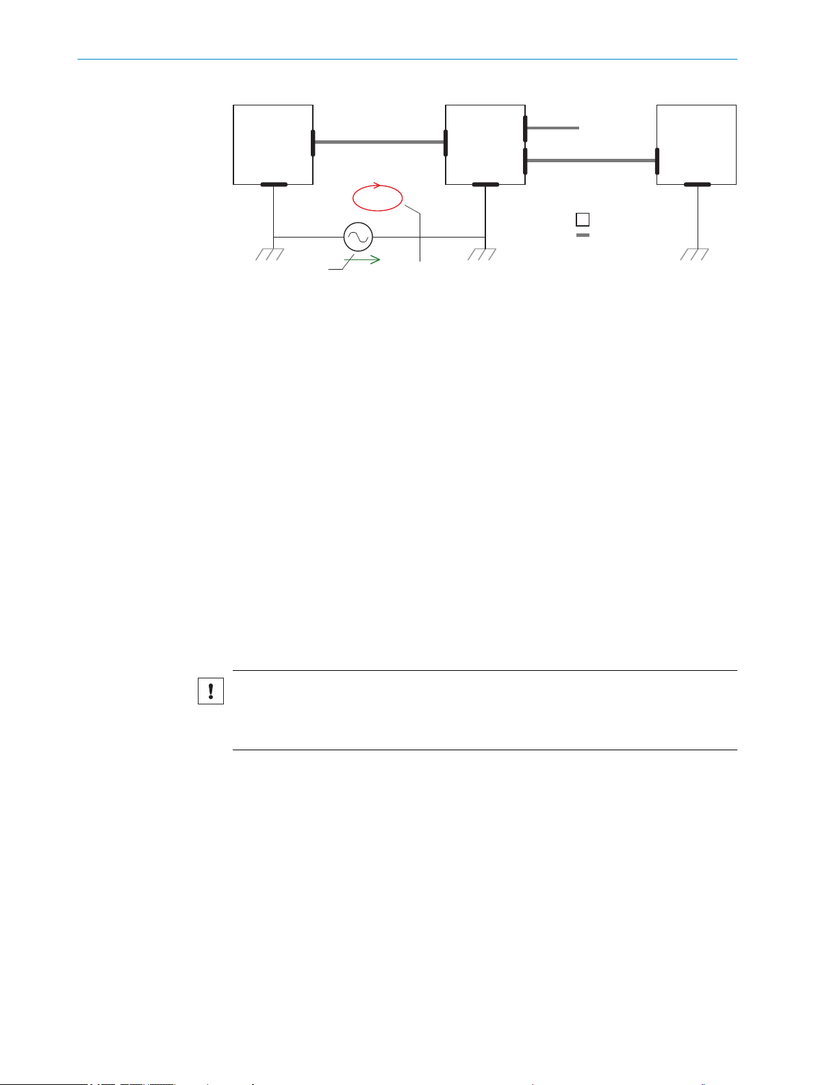
SICK
Device
8 57
Power Supply
U
= 9
= ß
1 3 4
I
6
System
Controller
Databus
Databus
2
2
ELECTRICAL INSTALLATION
6
Figure 17: Example: Occurrence of equipotential bonding currents in the system configuration
System controller
1
Data bus
2
Device
3
Voltage supply
4
Grounding point 2
5
Closed current loop with equalizing currents via cable shield
6
Ground potential difference
7
Grounding point 1
8
Metal housing
9
Shielded electrical cable
ß
If these conditions are not fulfilled, equipotential bonding currents can flow along the
cable shielding between the devices due to differing ground potentials and cause the
hazards specified. This is, for example, possible in cases where there are devices within
a widely distributed system covering several buildings.
Remedial measures
The most common solution to prevent equipotential bonding currents on cable shields
is to ensure low-impedance and current-carrying equipotential bonding. If this equipo‐
tential bonding is not possible, the following solution approaches serve as a suggestion.
NOTICE
We expressly advise against opening up the cable shields. This would mean that the
EMC limit values can no longer be complied with and that the safe operation of the
device data interfaces can no longer be guaranteed.
Measures for widely distributed system installations
On widely distributed system installations with correspondingly large potential differ‐
ences, the setting up of local islands and connecting them using commercially available
electro-optical signal isolators is recommended. This measure achieves a high degree
of resistance to electromagnetic interference.
36
O PE R AT I NG IN S TR U CT I ON S | CLV61x DualPort (PROFINET) 8017842/ZOK7/2019-02-01 | SICK
Subject to change without notice
Page 37
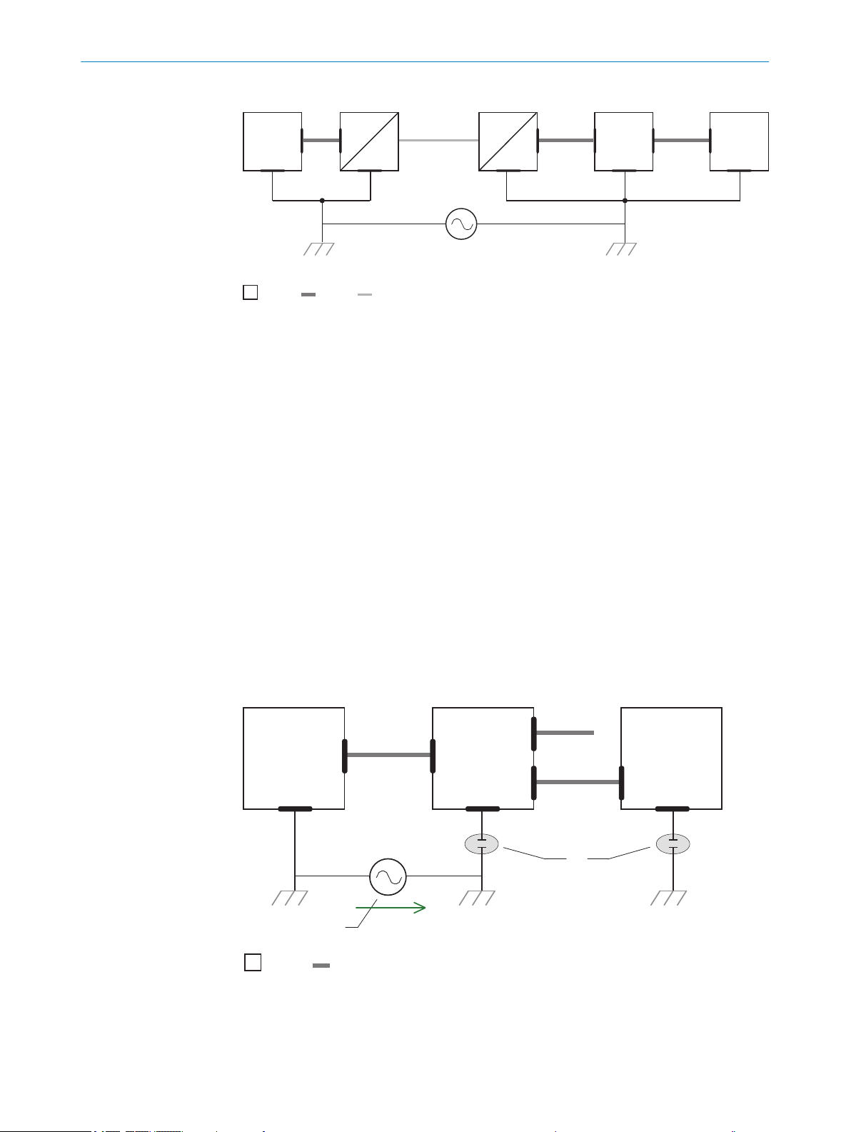
Electro-
optical
signal
isolator
Electro-
optical
signal
isolator
Power
Supply
SICK
Device
1 2 2 54
7 6
System
Controller
= 8
= 9
= ß
Databus
3
U
System
Controller
Power Supply
SICK
Device
9 7
6
31 4
5
8
= ß
= à
Databus
2
Databus
2
ELECTRICAL INSTALLATION 6
Figure 18: Example: Prevention of equipotential bonding currents in the system configuration by
the use of electro-optical signal isolators
System controller
1
Electro-optical signal isolator
2
Data bus
3
Device
4
Voltage supply
5
Grounding point 2
6
Grounding point 1
7
Metal housing
8
Shielded electrical cable
9
Optical fiber
ß
The use of electro-optical signal isolators between the islands isolates the ground loop.
Within the islands, a stable equipotential bonding prevents equalizing currents on the
cable shields.
Measures for small system installations
For smaller installations with only slight potential differences, insulated mounting of the
device and peripheral devices may be an adequate solution.
Figure 19: Example: Prevention of equipotential bonding currents in the system configuration by
the insulated mounting of the device
1
2
System controller
Data bus
8017842/ZOK7/2019-02-01 | SICK OP E RA T IN G I N ST R UC T IO N S | CLV61x DualPort (PROFINET)
Subject to change without notice
37
Page 38
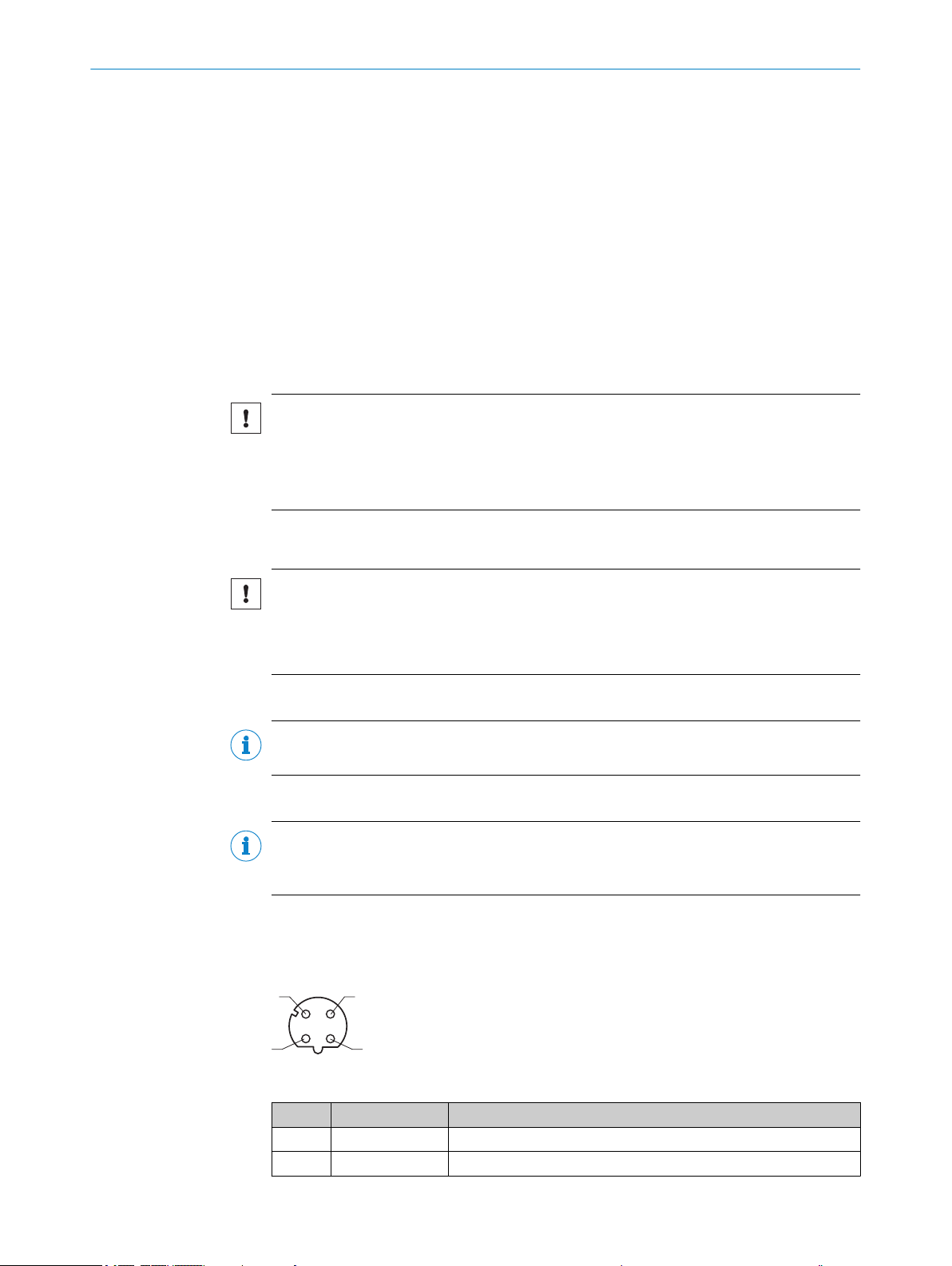
1
43
2
6 ELECTRICAL INSTALLATION
Device
3
Voltage supply
4
Grounding point 3
5
Insulated mounting
6
Grounding point 2
7
Ground potential difference
8
Grounding point 1
9
Metal housing
ß
Shielded electrical cable
à
Even in the event of large differences in the ground potential, ground loops are effec‐
tively prevented. As a result, equalizing currents can no longer flow via the cable shields
and metal housing.
NOTICE
The voltage supply for the device and the connected peripheral devices must also guar‐
antee the required level of insulation.
Under certain circumstances, a tangible potential can develop between the insulated
metal housings and the local ground potential.
6.3 Wiring instructions
NOTICE
Faults due to incorrect wiring.
Incorrect wiring may result in operational faults.
■
Follow the wiring notes precisely.
Pre-assembled cables
NOTE
Pre-assembled cables can be found online at: www.sick.com/CLV61x_Dual_Port
Pre-assembled cables with open cable end at one end:
NOTE
Information about pin, signal and wire color assignments see "Signal assignment of
cables with open cable end at one end", page 63 in the appendix.
6.4 Pin assignments for electrical connections
Connections P1 and P2 (PROFINET)
Figure 20: Female connector, M12, 4-pin, D-coded
Pin Signal Function
1 TD+ (Ethernet) Sender+
2 TD– (Ethernet) Sender–
38
O PE R AT I NG IN S TR U CT I ON S | CLV61x DualPort (PROFINET) 8017842/ZOK7/2019-02-01 | SICK
Subject to change without notice
Page 39

1
4 3
2
1
4 3
5
2
ELECTRICAL INSTALLATION 6
Pin Signal Function
3 RD+ (Ethernet) Receiver+
4 RD– (Ethernet) Receiver
Connection for POWER (CLV61x-Dx41x)
Figure 21: Male connector, M12, 4-pin, A-coded
Pin Signal Function
1 V
s
2 Reserved (Do not use.)
3 GND Ground
4 Reserved (Do not use.)
POWER and trigger input connection (CLV61x-Dx52x)
Supply voltage
Figure 22: Male connector, M12, 5-pin, A-coded
Pin Signal Function
1 V
s
2 Reserved (Do not use.)
3 GND Ground
4 Reserved (Do not use.)
5 Sensor 1 Digital switching input for external reading cycle
6.4.1 Wiring the PROFINET interface
1. Connect the device using the pre-assembled cables to the left and right of the
additional devices (IO devices) in the PROFINET network. Line or ring topology is
possible. If only one Ethernet connection is needed (e.g., last device in a line topol‐
ogy), either the P1 or P2 connection can be used. Fit a protective plug onto the
unused connection (as in delivery condition).
2. Switch on the supply voltage for the device. The device starts with a delay and
uses the default parameters set in the factory for the initialization. After a suc‐
cessful self-test, the blue LED on the device lights up to indicate the "Device
Ready" status.
Supply voltage
8017842/ZOK7/2019-02-01 | SICK OP E RA T IN G I N ST R UC T IO N S | CLV61x DualPort (PROFINET)
Subject to change without notice
39
Page 40

CLV61x-Dx41x
Dual Port
PLC 2 / HOST
CLV61x-Dx41x
Dual Port
CLV61x-Dx41x
Dual Port
CLV62x ...
CLV65x
Cable 3, optional
IO Controller
(MRP manager)
PROFINET
Cable 5 Cable 4 Cable 4 Cable 4
1
PROFINET
Cable 6 Cable 4 Cable 4 Cable 4
1
CLV61x-Dx52x
Dual Port
PLC 2 / HOST
CLV61x-Dx52x
Dual Port
CLV61x-Dx52x
Dual Port
CLV62x ...
CLV65x
IO Controller
(MRP manager)
PROFINET
Trigger 5Trigger 5Trigger 5
Cable 3, optional
PROFINET
6 ELECTRICAL INSTALLATION
Figure 23: Example of a PROFINET network design with a line or ring topology (CLV61x-Dx41x)
IO controller
1
PLC
2
Adapter cable (male connector, RJ45, 8-pin / male connector, M12, 4-pin, D-coded),
3
optional
Cable 1:1 (male connector, M12, 4-pin, D-coded / male connector, M12, 4-pin, D-coded)
4
Adapter cable (male connector, RJ45, 8-pin / male connector, M12, 4-pin, D-coded)
5
40
Figure 24: Example of a PROFINET network design with a line or ring topology (CLV61x-Dx52x)
IO controller
1
PLC
2
Adapter cable (male connector, RJ45, 8-pin / male connector, M12, 4-pin, D-coded),
3
optional
Cable 1:1 (male connector, M12, 4-pin, D-coded / male connector, M12, 4-pin, D-coded)
4
Reading cycle trigger (local)
5
Adapter cable (male connector, RJ45, 8-pin / male connector, M12, 4-pin, D-coded)
6
When ring topology is used, a device, such as a switch or the PROFINET controller, must
take over the function of the ring manager (MRP-Manager). The other devices must be
able to work as an MRP-Client. The device can be used as an MRP-Client, but not as an
MRP-Manager.
NOTE
The USB interface available depending on the type is only for temporary connection to a
PC for local configuration or device diagnostics.
O PE R AT I NG IN S TR U CT I ON S | CLV61x DualPort (PROFINET) 8017842/ZOK7/2019-02-01 | SICK
Subject to change without notice
Page 41

6.4.2 Wiring the switching input (CLV61x-Dx52x only)
Signal 3
3.32K
6.64K
"
§
$
Sensor GND
VS 2
V
S
V
S
V
in
5
!
PNP sensor 1
GND
Switching input 4
GND
V
S
Figure 25: Wiring the switching input
Trigger sensor (PNP sensor)
1
Supply voltage VS (VS = UV)
2
Input signal
3
Switching input of the device (“Sensor 1”)
4
Input voltage Vin (Vin = Ue)
5
For pin assignment, see respective device
!...$
ELECTRICAL INSTALLATION 6
If you would like an external sensor to trigger the read operation of the device, connect
the trigger sensor to the “Sensor 1” switching input.
Table 8: Connecting the switching input according to the application
Switching behav‐
ior
Properties
Electrical values
Current to input starts the internal reading interval of the device.
Default: Active high
•
Debouncing: Max. 10,000 ms (standard 10 ms)
•
Opto-decoupled, reverse polarity protected
•
Can be wired with PNP output of a trigger sensor
•
Low: | Vin | ≤ 2 V; | Iin | ≤ 0.3 mA
•
High: 6 V ≤ | Vin | ≤ 32 V; 0.7 mA ≤ | Iin | ≤ 5 mA
•
8017842/ZOK7/2019-02-01 | SICK OP E RA T IN G I N ST R UC T IO N S | CLV61x DualPort (PROFINET)
Subject to change without notice
41
Page 42

7 COMMISSIONING
7 Commissioning
7.1 Overview of the commissioning steps
Commissioning, adjustment, configuration and diagnostics of the device are performed
by default using the SOPAS ET configuration software.
The configuration can differ from this if, for example an across-the-board configuration
of the device is done centrally in the control environment by the PROFINET controller
(e.g PLC) (configuration using modules in the GSD file of the device). At each restart of
the PROFINET, the PROFINET controller overwrites and prioritizes the current device
parameters.
■
Commission device using factory default settings.
■
Connect the PC with the SOPAS-ET configuration software to the device.
■
To optimize the functionality of the device, adjust the device and adapt the config‐
uration as needed. The configuration data are stored and archived as a parameter
set (project file) on the PC as part of a backup concept. On device variants with
the optional memory card, the device also creates a permanent backup of the con‐
figuration data on the card.
■
Test the device for correct functionality in read operation.
NOTE
The procedure for incorporating the device into the PROFINET controller (PLC) and for
central parameterization using the PROFINET controller is described in the supplemen‐
tary information document “Bar code scanner CLV61x Dual Port (PROFINET)” in English
(part no. 8017978) and German (part no. 8017977).
The supplementary information can be found under "Documentation" on the online
product page at:
www.sick.com/CLV61x_Dual_Port
•
7.2 Install and launch the SOPAS ET configuration software
NOTE
The configuration software SOPAS ET, the current system prerequisites for the PC, and
the instructions for downloading can be found online at:
www.sick.com/SOPAS_ET
•
1. Electrically connect a device data interface with a PC that can connect to the Inter‐
net.
2. In accordance with the instructions, download and install the latest version of the
configuration software SOPAS ET, as well as the current device description file
(*.sdd) for the device. In this case, select the “Complete” option as selected by the
installation wizard. Administrator rights may be required on the PC to install the
software.
3. Start the "SOPAS ET" program after completing the installation. Path: Start > Pro‐
grams > SICK > SOPAS ET Engineering Tool > SOPAS.
4. Establish communication between SOPAS ET and the device with the automati‐
cally launching wizard. To do so, select the device under the devices available
depending on the connected communication interface, e.g., Ethernet. (Default Eth‐
ernet address: IP address: 192.168.0.1, subnet mask: 255.255.255.0).
SOPAS ET establishes communication with the device and loads the associated
device description file. The device project tree opens.
42
O PE R AT I NG IN S TR U CT I ON S | CLV61x DualPort (PROFINET) 8017842/ZOK7/2019-02-01 | SICK
Subject to change without notice
Page 43

7.3 Adjust the device
Parameter set in the
main memory of the
device 6
Permanently saved
parameter set of the
device 5
Factory default setting of
the device 7
Device 2Optional: 1 PC with SOPAS ET
Configuration Software 3
MicroSD memory card 4
Volatile memory à
Opened project file
with current parameter
set of the device 8
Volatile memory à
Non-volatile memory ß
Non-volatile memory ß
Saved project file (*.sopas)
with archived parameter
set of the device 9
Data base on e. g. hard drive
(non-volatile memory) á
Permanently saved
parameter set of the
device 5
Non-volatile memory ß
For complete adjustment of the device, the electrical installation must be complete and
the device must have been commissioned.
1. Loosen the bracket screws so that the device can be aligned.
2. Align the device so that the angle between the scanning line and the bar code
stripes is almost 90°.
3. To prevent interference reflections, arrange the device as close to being plane-par‐
allel to the object surface as possible.
4. Manually place objects with bar codes one after the other into the reading range
of the device, see "Technical data", page 55.
5. Check the reading result with the SOPAS ET configuration software.
6. When doing so, place objects at different positions (angles) in the reading field
and ensure that the limit values for the permitted reading angles are not
exceeded, see "Angle alignment of the device", page 30.
7. Align the device so that the good read rate is between 70% and 100%.
8. Tighten the screws on the device.
7.4 Initial commissioning
The device is adjusted to the application situation on site using the SOPAS ET configura‐
tion software on the PC. The default factory settings of the device are the starting point
for this. Their parameter values (configuration data) can be adapted in the working
memory of the device for optimization purposes. To do so, the user creates an applica‐
tion-specific parameter set with the SOPAS ET configuration software or changes the
set later as required. The user then loads the current parameter set to the permanent
parameter memory of the device.
COMMISSIONING 7
8017842/ZOK7/2019-02-01 | SICK OP E RA T IN G I N ST R UC T IO N S | CLV61x DualPort (PROFINET)
Subject to change without notice
Memory organization for parameter set
The following diagram shows the memory management principle for the involved inter‐
nal and external components:
Figure 26: Configuring with SOPAS ET and saving the parameter set
Optional (only CLV61x-DxxXxx, with X= 3 or 4)
1
Device
2
PC with SOPAS ET configuration software
3
MicroSD memory card
4
Permanently saved device parameter set
5
Parameter set in the working memory of the device
6
Factory-set defaults for the device
7
Opened project file with current device parameter set
8
43
Page 44

7 COMMISSIONING
Saved project file with archived device parameter set
9
Nonvolatile memory
ß
Volatile memory
à
Database on the hard drive, for example (nonvolatile memory)
á
Save process:
Depending on type, the device may be optionally equipped with a microSD memory
card:
Each time the currently valid parameter set is saved in the device with the “Perma‐
•
nent” option, the parameter set is also permanently saved externally on the mem‐
ory card.
44
O PE R AT I NG IN S TR U CT I ON S | CLV61x DualPort (PROFINET) 8017842/ZOK7/2019-02-01 | SICK
Subject to change without notice
Page 45

8 Operation
O
Ö
Ö
Ready
G Read
N Read
HW Err
UserDef1
O
Ö
SF
P1 LNK/ACT
P2 LNK/ACT
BF
1
2
3
8.1 Operating and status indicators
8.1.1 Operator interface
The device can be configured according to application in the following manner:
■
Locally at the device with the SOPAS ET configuration software. Protection of the
parameter set as a configuration file on the PC in SOPAS ET. Access to the device
via Aux interface (USB or Ethernet).
■
As an alternative to the SOPAS ET configuration software, command strings are
available, upon which the operator interface of the configuration software is also
based. These are also for the triggering of device functions (e.g. reading).
■
Centrally by the PROFINET controller via PROFINET using the GSD configuration.
Protection of the parameter set as a configuration file in the PROFINET controller.
Each time the PROFINET is restarted, the device is reconfigured.
NOTE
The procedure for incorporating the device into the PROFINET controller (PLC) and for
central parameterization using the PROFINET controller is described in the supplemen‐
tary information document “Bar code scanner CLV61x Dual Port (PROFINET)” in English
(part no. 8017978) and German (part no. 8017977).
The supplementary information can be found under “Documentation” on the online
product page at:
OPERATION 8
www.sick.com/CLV61x_Dual_Port
•
The SOPAS ET configuration software is used for device diagnostics in case of a fault.
In normal operation, the device operates fully automatically.
8.1.2 Optical status indicators on the device
Figure 27: LEDs on the housing
Signal color allocation for status and events, displayed by sensor LED
8017842/ZOK7/2019-02-01 | SICK OP E RA T IN G I N ST R UC T IO N S | CLV61x DualPort (PROFINET)
Subject to change without notice
1
Sensor LED (RGB), 1 x
2
Network LED for communication via PROFINET, 4 x
3
Sensor LED
Table 9: Display behavior of the sensor LED
Color Display LED Status
– – Off Device without supply voltage
45
Page 46

8 OPERATION
Color Display LED Status
Magenta – Flashing Device with heating (CLV61x-DxxxxF0):
Device not yet ready for operation, still in the
warm-up phase.
Blue Ready Steadily lit After switching on or after successful firmware
download:
Self-test successful, device ready for operation
– – Goes out After switching on:
Parameter download to / upload from device
Green G Read Lights up
briefly
Red N Read Lights up
briefly
Red HW Err Steadily lit Hardware error
Light blue UserDef1 Off UserDef1 (reserved)
Red
Blue
Red Steadily lit Firmware download:
Further indicators Alternating
flashing
Reading successful (Good Read)
Reading unsuccessful (No Read)
Firmware download
Error: Completion not successful
Network LEDs
Table 10: Display behavior of the sensor LEDs
Display LED Color Status
1)
SF
2)
BF
P1 LNK/ACT Off – Device not connected to any active network; no
P1 LNK Steadily lit Green Device connected to active network, e.g. with
P1 ACT Flickering Orange Device is sending or receiving data
Off – Device without internal error
Steadily lit Red The device activates the internal PROFINET
module
Flashing Red Using the PROFINET TOOL, a blink request was
sent to the device for device identification
Off – Data exchange between device and PROFINET
controller via PROFINET possible
Steadily lit Red No connection between device and PROFINET
controller.
Possible causes:
Bus not connected electrically
•
PROFINET controller not available or
•
switched off
Incorrect PROFINET name
•
Wrong GSD file used
•
Wrong GSD module selected
•
Flashes cyclically Red Flash frequency 0.5 Hz.
Possible causes:
Configuration error in the PROFINET con‐
•
troller (e.g. ID wrong), no data exchange
Error in the PROFINET controller when con‐
•
figuring with modules, no data exchange
data traffic possible
an Ethernet switch (switched-on)
46
O PE R AT I NG IN S TR U CT I ON S | CLV61x DualPort (PROFINET) 8017842/ZOK7/2019-02-01 | SICK
Subject to change without notice
Page 47

OPERATION 8
Display LED Color Status
P2 LNK/ACT Off – Device not connected to any active network; no
data traffic possible
P2 LNK Steadily lit Green Device connected to active network, e.g. with
an Ethernet switch (switched-on)
P2 ACT Flickering Orange Device is sending or receiving data
1)
SF = System Failure.
2)
BF = Bus Failure.
8017842/ZOK7/2019-02-01 | SICK OP E RA T IN G I N ST R UC T IO N S | CLV61x DualPort (PROFINET)
Subject to change without notice
47
Page 48

9 MAINTENANCE
9 Maintenance
9.1 Maintenance
During operation, the device works maintenance-free.
Depending on the assignment location, the following preventive maintenance tasks
may be required for the device at regular intervals:
NOTE
No maintenance is required to ensure compliance with the laser class.
Table 11: Maintenance schedule
Maintenance work Interval To be carried out
Clean housing and front screen Cleaning interval depends on ambi‐
Check screw connections and plug
connectors
Check that the unused connections
are sealed with protective caps or
plugs
ent conditions and climate.
Interval depends on the place of use,
ambient conditions, or operational
regulations. Recommended: At least
every 6 months.
Interval depends on ambient condi‐
tions and climate. Recommended: At
least every 6 months.
by
Specialist
Specialist
Specialist
9.2 Cleaning
9.2.1 Cleaning the device
At regular intervals (e.g. weekly), check the reading window and the housing of the
device for accumulated dirt. This is especially relevant in harsh operating environments
(dust, abrasion, damp, fingerprints, etc.). The reading window lens must be kept clean
and dry for reading.
This action, along with any cleaning, ensures full optical reading performance of the
device, and allows it to adequately dissipate heat resulting from internal power loss.
NOTICE
Device damage due to improper cleaning
Improper cleaning may result in device damage.
■
■
Clean the reading window
The type of screen material used in the reading window can be found on the type label:
CLV61x-DxxxXx, with X = 0: glass, X = 1: plastic
Never use cleaning agents containing aggressive substances.
Never use sharp objects for cleaning.
48
O PE R AT I NG IN S TR U CT I ON S | CLV61x DualPort (PROFINET) 8017842/ZOK7/2019-02-01 | SICK
Subject to change without notice
Page 49
MAINTENANCE
Glass lens
NOTICE
Damage to the Reading Window!
Reduced reading performance due to scratches or streaks on the reading window!
Do not use any aggressive cleaning agent.
b
Do not use any cleaning agent likely to cause increased abrasion (e.g. powder).
b
Avoid any movements that could cause scratches or abrasions on the reading win‐
b
dow.
Plastic lens
NOTICE
Damage to the Reading Window!
Reduced reading performance due to scratches or streaks on the reading window.
Clean the reading window only when wet.
b
Use a mild cleaning agent that does not contain powder additives. Do not use
b
aggressive cleaning agents, such as acetone, etc.
Avoid any movements that could cause scratches or abrasions on the reading win‐
b
dow.
9
NOTE
Static charge causes dust particles to adhere to the reading window. This effect can be
avoided by using an anti-static SICK plastic cleaner (part number 5600006) in combi‐
nation with the SICK lens cloth (part number 4003353).
Cleaning procedure:
CAUTION
Optical radiation: Laser class 2
The human eye is not at risk when briefly exposed to the radiation for up to 0.25 sec‐
onds. Exposure to the laser beam for longer periods of time may cause damage to the
retina. The laser radiation is harmless to human skin.
■
Do not look into the laser beam intentionally.
■
Never point the laser beam at people's eyes.
■
If it is not possible to avoid looking directly into the laser beam, e.g., during com‐
missioning and maintenance work, suitable eye protection must be worn.
■
Avoid laser beam reflections caused by reflective surfaces. Be particularly careful
during mounting and alignment work.
■
Do not open the housing. Opening the housing may increase the level of risk.
■
Current national regulations regarding laser protection must be observed.
Switch off the device for the duration of the cleaning operation. If this is not possi‐
b
ble, use suitable laser protection goggles. These must effectively absorb the radia‐
tion at the device’s wavelength effectively, see "Technical data", page 55.
Glass lens: Remove dust from the reading window using a soft, clean brush. If nec‐
b
essary, also clean the reading window with a clean, damp, lint-free cloth, and a
mild anti-static lens cleaning fluid.
Plastic lens: Clean the reading window only with a clean, damp, lint-free cloth, and
b
a mild anti-static lens cleaning fluid.
8017842/ZOK7/2019-02-01 | SICK OP E RA T IN G I N ST R UC T IO N S | CLV61x DualPort (PROFINET)
Subject to change without notice
49
Page 50

9 MAINTENANCE
NOTICE
If the reading window is damaged by scratches, cracks or breaks, the lens must be
replaced. Contact SICK customer service to arrange this.
If the reading window is cracked or broken, the device must be taken out of opera‐
b
tion immediately and repair by SICK must be arranged immediately due to safety
reasons.
Cleaning the housing
In order to ensure that heat is adequately dissipated, the housing surface must be kept
clean.
Clear the build up of dust on the housing with a soft brush.
b
9.2.2 Cleaning surfaces that have an optical effect
Depending on how the reading station is equipped, additional local sensors may have
other surfaces with an optical effect installed (e.g. single-beam photoelectric safety
switches for an external reading pulse). Contamination on these sensors can result in
faulty switching behavior.
To avoid faulty switching behavior, remove contamination from the optical effect
b
surfaces of external sensors.
50
Figure 28: Cleaning the external optical sensors (read pulse encoder)
O PE R AT I NG IN S TR U CT I ON S | CLV61x DualPort (PROFINET) 8017842/ZOK7/2019-02-01 | SICK
Subject to change without notice
Page 51
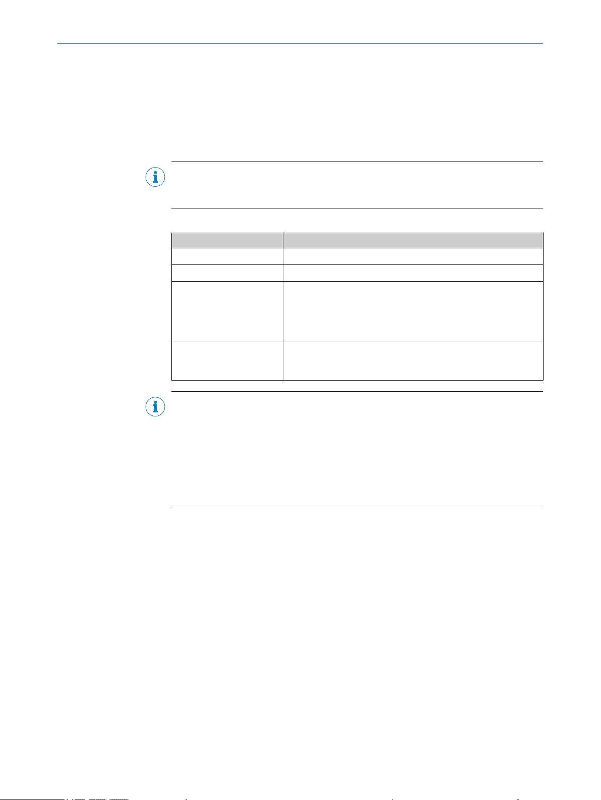
10 Troubleshooting
10.1 Overview of possible errors and faults
Possible faults and corrective actions are described in the table below for troubleshoot‐
ing. For faults that cannot be resolved using the information below, please contact
SICK Service. To find your agency, see the final page of this document.
NOTE
Before calling, make a note of all type label data such as type designation, serial num‐
ber, etc., to ensure faster assistance.
Table 12: Errors and faults
Situation Error/fault
Mounting
Electrical installation
Configuration
Operation
Device poorly aligned to objects with bar codes (e.g., dazzle).
■
Data interfaces of the device incorrectly wired.
■
Functions not adapted to local conditions, e.g., parameters for
■
the data interface not set correctly.
Device limits not observed, e.g., reading distance, aperture
■
angle.
Trigger source for reading pulse not selected correctly.
■
Reading pulse control incorrect and/or not suitable for the
■
object.
Device faults (hardware/software).
■
TROUBLESHOOTING 10
NOTE
Further measures for eliminating possible errors and faults when incorporating the
device into the PROFINET controller (PLC) are described in the supplementary informa‐
tion document “Bar code scanner CLV61x Dual Port (PROFINET)" in English (part no.
8017978) and German (part no. 8017977).
The supplementary information can be found under "Documentation" on the online
product page at:
www.sick.com/CLV61x_Dual_Port
•
10.2 Detailed fault analysis
10.2.1 LEDs on the device
The statuses that can be read from the upper sensor LED on the device housing (see
"Optical status indicators on the device", page 45) include:
■
Operational readiness (Ready)
■
Reading result status (Good Read or No Read)
■
Hardware fault
■
Firmware download status
The status of communications with the PROFINET can be read from the four lower net‐
work LEDs:
■
Connection status of the device with PROFINET
■
Data traffic with the controller
The LED display can indicate any errors or faults with this. Further information for this
can be found in the system information.
8017842/ZOK7/2019-02-01 | SICK OP E RA T IN G I N ST R UC T IO N S | CLV61x DualPort (PROFINET)
Subject to change without notice
51
Page 52

10 TROUBLESHOOTING
10.2.2 System information
The device outputs any occurring faults in different ways. Fault output is staggered,
allowing for an increasingly detailed level of analysis:
•
•
10.3 Status log
NOTE
The status log is retained even after switching the device off and on again.
The device distinguishes between four types of fault:
■
■
■
■
The device saves only the last five entries for each fault type.
Communication errors can occur when transmitting telegrams to the device. The
device then returns a fault code.
For faults that occur during reading, the device writes fault codes in the status log
(see "Status log", page 52).
Information
Warning
Fault
Critical fault
10.3.1 Displaying the Status Log
To display the status log, the SOPAS ET configuration software must be connected with
the device online.
1. Connect the SOPAS ET configuration software to the device.
2. Open CLV61x in the project tree: SERVICE > SYSTEM STATUS > SYSTEM INFORMATION
tab.
10.4 Repairs
Repair work on the device may only be performed by qualified and authorized person‐
nel from SICK AG. Interruptions or modifications to the device by the customer will inval‐
idate any warranty claims against SICK AG.
10.5 Returns
Do not dispatch devices to the SICK Service department without consultation.
b
The device must be sent in the original packaging or an equivalent padded pack‐
b
aging.
NOTICE
Optional memory card
Check whether there is a memory card in the card slot of the device. If yes, remove
•
the memory card from the faulty device in de-energized state.
Do not send in the memory card!
•
52
NOTE
To enable efficient processing and allow us to determine the cause quickly, please
include the following when making a return:
■
Details of the contact person
■
Description of the application
■
Description of the fault that occurred
O PE R AT I NG IN S TR U CT I ON S | CLV61x DualPort (PROFINET) 8017842/ZOK7/2019-02-01 | SICK
Subject to change without notice
Page 53

10.6 Replacing the device
Faulty or damaged devices must be dismantled and replaced with new or repaired
devices of the same type.
10.6.1 Disassembling the device
1. Switch off the supply voltage to the device.
2. Detach all connecting cables from the device.
3. Remove the device from the bracket. When doing so, mark the position and align‐
ment of the device on the bracket or surroundings.
10.6.2 Replacing the device
NOTE
For further details, see the supplementary information document “Bar code scanner
CLV61x Dual Port (PROFINET)” in English (part no. 8017978) and German (part no.
8017977).
The supplementary information can be found under "Documentation" on the online
product page at:
www.sick.com/CLV61x_Dual_Port
•
TROUBLESHOOTING 10
1. Align and mount the new or repaired device (see "Mounting", page 26). When
doing so, note the previously applied markings on the bracket or surroundings (see
"Disassembling the device", page 53).
2. Reconnect the connecting cables to the device.
3. Switch on the supply voltage for the device. The device starts up with the default
setting (new device).
4. Depending on the selected configuration type, proceed as follows:
– Central configuration via GSD parameterization: When the PROFINET is
restarted, the PROFINET controller automatically parameterizes the device.
– Local automated configuration for device variants with an optional memory
card: The replacement device automatically transfers the saved parameter
set from the memory card into its permanent memory.
– Local manual configuration with SOPAS ET:
Option a: Download the configuration previously stored on the PC as part of
the backup concept to the device (via USB or Ethernet, depending on the
type) and permanently store it in the device.
Option b: Transfer the saved configuration of the previous device via profile
programming. To do this, create and print out profile programing bar codes in
SOPAS ET. When starting the device, hold the bar codes in the device’s read‐
ing area to permanently parameterize the scanner.
If automated PN name assignment for the device has been configured and activated in
the PROFINET controller, the following conditions apply:
Central configuration: The entire permanently stored parameter set of the new
•
device being installed must be set to default (same as state of new device upon
delivery).
Local configuration: At least the “PN Name” field in the device’s parameter set
•
must be empty.
The device then automatically obtains the required PN names from the PROFINET con‐
troller when the supply voltage is switched on.
8017842/ZOK7/2019-02-01 | SICK OP E RA T IN G I N ST R UC T IO N S | CLV61x DualPort (PROFINET)
Subject to change without notice
53
Page 54

11 DISPOSAL
11 Disposal
If a device can no longer be used, dispose of it in an environmentally friendly manner in
accordance with the applicable country-specific waste disposal regulations. Do not dis‐
pose of the product along with household waste.
NOTICE
Danger to the environment due to improper disposal of the device.
Disposing of devices improperly may cause damage to the environment.
Therefore, observe the following information:
■
Always observe the valid regulations on environmental protection.
■
Separate the recyclable materials by type and place them in recycling containers.
54
O PE R AT I NG IN S TR U CT I ON S | CLV61x DualPort (PROFINET) 8017842/ZOK7/2019-02-01 | SICK
Subject to change without notice
Page 55

12 Technical data
NOTE
The relevant online data sheet for your product, including technical data, dimensional
drawing, and connection diagrams can be downloaded, saved, and printed from the
Internet:
www.sick.com/CLV61x_Dual_Port
•
These operating instructions provides additional technical data if required.
TECHNICAL DATA 12
12.1
optical lens system
Table 13: CLV61x Dual Port: technical data for optics
Working range Long range Long range
Scanning Method Line or grid scanner 1), type-dependent, identifier see "Type code",
Reading window orienta‐
tion
Aperture angle ≤ 50°
Focus Fixed focus
Resolution 0.35 mm ... 0.5 mm 0.35 mm ... 1 mm
Reading areas see "Reading field diagrams", page 58
Scanning frequency 400 Hz to 1,000 Hz
Light source Laser LED, visible red light (λ = 655 nm)
MTTF (laser diode) 40,000 h at 25 °C
Laser class Class 2 according to EN/IEC 60825-1:2014. Identical laser class
Laser power P = 1.5 mW maximum, P
Laser pulse duration < 300 µs
1)
Grid height approx. 15 mm at a reading distance of 200 mm
CLV615 CLV618
page 13
On the front or to the side (light emission at 105° relative to the
longitudinal axis of the device), type-dependent, identifier see
"Type code", page 13
for issue EN/IEC 60825-1:2007.
Complies with 21 CFR 1040.10 except for tolerances according to
Laser Notice no. 50 of June 24, 2007.
P = 3.2 mW maximum, P
< 1.0 mW average
< 1.0 mW average
12.2 Performance
Table 14: CLV61x Dual Port: technical data for performance
Bar code types Code 39, Code 128, Code 93, Codabar, UPC / GTIN / EAN,
2/5 Interleaved, Pharmacode
Print ratio 2:1 ... 3:1
No. of codes per scan 1 ... 10 (standard decoder)
1 ... 6 (SMART620)
No. of codes per reading
interval
No. of characters per read‐
ing interval
8017842/ZOK7/2019-02-01 | SICK OP E RA T IN G I N ST R UC T IO N S | CLV61x DualPort (PROFINET)
Subject to change without notice
1)
1 to 50 (auto-discriminating)
Max. 50 characters (max. 1,500 characters across all bar codes
per reading interval)
55
Page 56

12 TECHNICAL DATA
12.3 Interfaces
No. of multiple readings 1 to 99
1)
Reading interval: The time window generated internally by the reading pulse for code detection and evalu‐
ation
Table 15: CLV61x Dual Port: technical data for interfaces
Ethernet (10/100 MBit/s) Host interface:
PROFINET device function
•
Protocols: PROFINET, Conformance Class B and Ethernet
•
TCP/IP
2-port Ethernet in accordance with IEEE 802.3 (100 Mbit/s,
•
full-duplex transmission, 2-port switch, auto-crossover)
Maximum data length limited to 4,000 bytes by communica‐
•
tion mode (fragmentation protocol).
AUX interface: configuration or diagnostics
1)
USB
AUX interface (USB 2.0) for configuration or diagnostics. Typedependent, identifier see "Type code", page 13
Digital switching inputs 1 x software controlled via PROFINET control bits
1 x, type-dependent, identifier see "Type code", page 13
Digital switching outputs 4 x software controlled via PROFINET control bits
Reading pulse
Fieldbus input, free, auto pulse, command (data interface)
•
Switching input, type-dependent, identifier see "Type code",
•
page 13
Optical indicators 1 x RGB-LED multi-color, with signal color allocation for events
4 x LED, for PROFINET
Acoustic indicators ‒
Service function Backup of parameterization data (parameter cloning) to a location
outside the device memory:
Externally by inserting optional microSD memory card into the
device. Type-dependent, identifier see "Type code", page 13
Configuration SOPAS ET configuration software, commands, GSD parameteriza‐
tion
1)
Service interface, for temporary use only.
12.4 Mechanics/electronics
Table 16: Technical data on mechanics/electronics
Electrical connection Swivel connector with:
Supply voltage V
Power consumption
56
O PE R AT I NG IN S TR U CT I ON S | CLV61x DualPort (PROFINET) 8017842/ZOK7/2019-02-01 | SICK
2 x PROFINET connection (female connector, M12, 4-pin, D-
■
coded)
Cable (0.9 m), type-dependent with POWER connection (male
■
connector, M12, 4-pin, A-coded) or with POWER + trigger input
connection (male connector, M12, 5-pin, A-coded). Code see
"Type code", page 13
1 x USB connection 1), type-dependent, identifier see "Type code",
page 13
s
Devices without heating: DC 10 V ... 30 V
Devices with heating: DC 18 V ... 30 V
LPS or NEC Class 2
Reverse polarity protected
2)
Devices without heating: Typically 5 W
Devices with heating: Max. 15 W
Subject to change without notice
Page 57
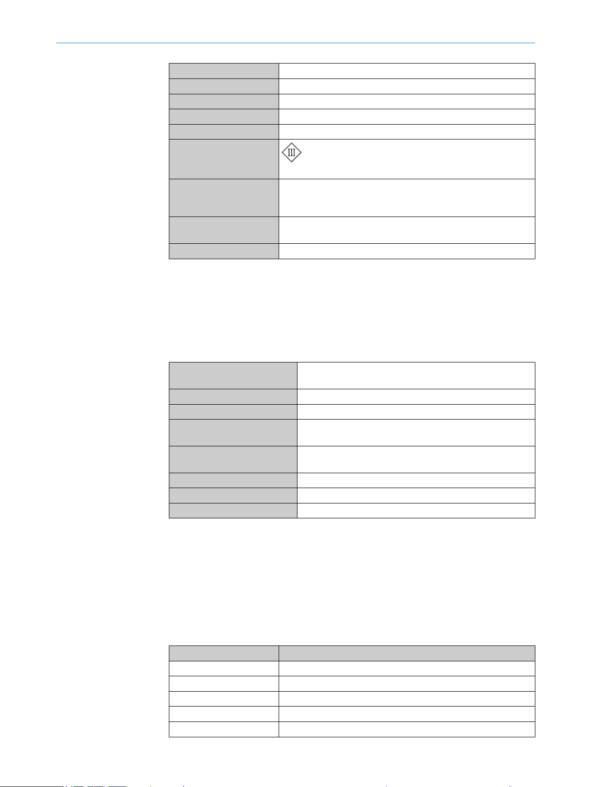
TECHNICAL DATA 12
Housing Cast aluminum
Housing color Light blue (RAL 5012)
Front screen Glass (optionally plastic), identifier see see "Type code", page 13
Safety EN 60950-1: 2011-01
Enclosure rating IP 65 (EN 60529: 2014-09)
Protection class
Intended for operation in SELV systems (safety extra low voltage).
3)
Weight
Dimensions Device with front light emission: 61 mm x 96 mm x 38 mm
Conformity CE, UL
1)
Service interface, for temporary use only.
2)
For switching outputs without load.
3)
With connecting cable, male connector and glass reading window.
4)
Only UL-certified if the type label contains the UL logo and the UL conditions are complied with during
device operation. For further information, see "Certification in accordance with UL60950", page 63.
Device with front reading window: 290.5 g
Device with side reading window: 310 g
Device with side reading window and heating: 346 g
Device with side light emission: 80 mm x 96 mm x 38 mm
4)
12.5 Ambient data
Table 17: CLV61x Dual Port: technical data for ambient conditions
Electromagnetic compatibility
(EMC)
Vibration resistance EN 60068-2-6: 2008-02
Shock resistance EN 60068-2-27: 2009-05
Ambient operating temperature Device without heating: 0 °C ... +40 °C
Storage temperature Device without heating: ‒20 °C ... +70 °C
Permissible relative humidity 0% ... 90%, non-condensing
Ambient light immunity 2,000 lx, on bar code
Bar code print contrast (PCS) ≥ 60 %
12.6 Dimensional drawings
Dimensions see "Device view", page 16.
12.7 Reading fields
12.7.1 Specification diagram for reading fields
Table 18: Reading conditions for reading field diagrams
Characteristic Value
Test code Code 39/ITF
Print ratio 2:1
Print contrast > 90%
Tilt ±10°
Ambient light ≤ 2,000 lx
Radiated emission: EN 61000-6-4: 2007-01 + A1: 2011-02
Electromagnetic immunity: EN 61000-6-2: 2005-08
Device with heating: ‒35 °C ... +40 °C
Device with heating: ‒35 °C ... +70 °C
8017842/ZOK7/2019-02-01 | SICK OP E RA T IN G I N ST R UC T IO N S | CLV61x DualPort (PROFINET)
Subject to change without notice
57
Page 58

150
(5.91)
(5.91) (7.87) (9.84) (11.81) (13.78)
(
–5.91)
–150
100
(3.94)
(3.94)
(
–3.94)
–100
50
(1.97)
(1.97)
(
–1.97)
–50
0
Reading distance in mm (inch) 2
Resolution
3
b: 0.35 mm (13.8 mil)
c: 0.50 mm (19.7 mil)
0 50 100 150 200 250 300 350
Reading field height in mm (inch) 1
b
c
12 TECHNICAL DATA
Characteristic Value
Good read rate > 75 %
12.7.2 Reading field diagrams
CLV615: Long Range
Figure 29: Reading field diagram: CLV615 with reading window on side
Reading field height in mm (inch)
1
Reading distance in mm (inch)
2
Resolution
3
58
O PE R AT I NG IN S TR U CT I ON S | CLV61x DualPort (PROFINET) 8017842/ZOK7/2019-02-01 | SICK
Subject to change without notice
Page 59

CLV618: Long range
Reading distance in mm (inch) 2
Reading field height in mm (inch) 1
a
b
c
800
(31.5)
600
(23.62)
400
(15.75)
200
(7.87)
0
Resolution
3
a: 0.35 mm (13.8 mil)
c: 1.0 mm (39.4 mil)
b: 0.50 mm (19.7 mil)
–400
(–15.75)
–300
(–11.81)
–200
(–7.87)
–100
(–3.94)
100
(3.94)
200
(7.87)
300
(11.81)
400
(15.75)
TECHNICAL DATA 12
8017842/ZOK7/2019-02-01 | SICK OP E RA T IN G I N ST R UC T IO N S | CLV61x DualPort (PROFINET)
Subject to change without notice
Figure 30: Reading field diagram: CLV618 with reading window on front
Reading field height in mm (inch)
1
Reading distance in mm (inch)
2
Resolution
3
59
Page 60

800
(31.5)
600
(23.62)
400
(15.75)
200
(7.87)
0
Reading distance in mm (inch)
2
Resolution 3
a: 0.35 mm (13.8 mil)
c: 1.0 mm (39.4 mil)
b: 0.50 mm (19.7 mil)
–400
(–15.75)
–300
(–11.81)
–200
(–7.87)
–100
(–3.94)
100
(3.94)
200
(7.87)
300
(11.81)
400
(15.75)
0
Reading field height in mm (inch)
1
a
b
c
12 TECHNICAL DATA
CLV618: Long Range
O PE R AT I NG IN S TR U CT I ON S | CLV61x DualPort (PROFINET) 8017842/ZOK7/2019-02-01 | SICK
60
Figure 31: Reading field diagram: CLV618 with reading window on side
Reading field height in mm (inch)
1
Reading distance in mm (inch)
2
Resolution
3
Subject to change without notice
Page 61

13 Accessories
NOTE
Accessories and where applicable mounting information can be found online at:
www.sick.com/CLV61x_Dual_Port
•
Accessories for CLV61x Dual Port bar code scanners with heating
Brackets:
Bracket, part number 2050705
•
Bracket, part number 2058082
•
13.1 Quick release in combination with mounting bracket
This chapter illustrates how to mount brackets on the device where the brackets involve
a combination of two or more individual mounting components. Illustration may differ
from actual device.
ACCESSORIES 13
8017842/ZOK7/2019-02-01 | SICK OP E RA T IN G I N ST R UC T IO N S | CLV61x DualPort (PROFINET)
Subject to change without notice
61
Page 62

(19)
(3.5)
10
11
4
38
10
48
16
22
10
19
(M5)
(Ø 7.5)
5
4
4
5
2
1
6
7
3
13 ACCESSORIES
Figure 32: View of the quick release (dimensions in mm) and combination with mounting bracket
Width across flats, size 3
1
M5 thread hole, screw-in depth max. 8 mm
2
Quick release (part number 2025526)
3
Quick release, part 1
4
Quick release, part 2
5
Width across flats, size 3
6
Mounting bracket (part number 2020410)
7
62
O PE R AT I NG IN S TR U CT I ON S | CLV61x DualPort (PROFINET) 8017842/ZOK7/2019-02-01 | SICK
Subject to change without notice
Page 63

14 Appendix
ð
1
4 3
2
1 2
14.1 EU declaration of conformity / Certificates
The EU declaration of conformity and other certificates can be downloaded from the
Internet at:
www.sick.com/CLV61x_Dual_Port
•
14.2 Certification in accordance with UL60950
The devices in the CLV61x, CLV61x Dual Port, CLV62x, CLV63x, CLV64x, CLV65x series
are certified to UL60950-1; the UL file number is E244281-A6. The devices must be
supplied by LPS or Class 2 power supply units in order to ensure UL-compliant opera‐
tion.
UL certification is only valid with corresponding device identification on the type label of
the respective device, see "Type label", page 13.
APPENDIX 14
Laser power and laser warning notes, see "Operational safety and particular haz‐
•
ards", page 10.
IP65 enclosure rating of the devices not checked by UL.
•
14.3 Dimensional drawings (electronic)
Current dimensional drawings in various electronic formats can be downloaded online:
www.sick.com/CLV61x_Dual_Port
•
14.4 Signal assignment of cables with open cable end at one end
14.4.1 PROFINET connection
Adapter cable, straight male connector
Part no. 6048247 (2 m), part no. 6048248 (5 m), part no. 6048249 (10 m), shielded
For CLV61x Dual Port PROFINET
Figure 33: Adapter cable, e.g., part no. 6048247 (2 m)
Male connector, M12, 4-pin, straight, D-coded (front view)
1
Illustration may differ
2
8017842/ZOK7/2019-02-01 | SICK OP E RA T IN G I N ST R UC T IO N S | CLV61x DualPort (PROFINET)
Subject to change without notice
Table 19: Signal assignment of adapter cable with open end
Pin Signal Function Wire color
1 TD+ (Ethernet) Sender+ Yellow
2 TD– (Ethernet) Sender– White
3 RD+ (Ethernet) Receiver+ Orange
4 RD– (Ethernet) Receiver– Blue
63
Page 64

ð
1
4 3
2
1
2
ð
1
43
5
2
1 2
14 APPENDIX
14.4.2 PROFINET connection
Adapter cable, angled male connector
Part no. 6048256 (2 m), part no. 6048257 (5 m), part no. 6048258 (10 m), part no.
6048259 (25 m), shielded
For CLV61x Dual Port PROFINET
Figure 34: Adapter cable, e.g., part no. 6048256 (2 m)
1
2
Male connector, M12, 4-pin, angled at 90°, D-coded (front view)
Illustration may differ
Table 20: Signal assignment of adapter cable with open end
Pin Signal Function Wire color
1 TD+ (Ethernet) Sender+ Yellow
2 TD– (Ethernet) Sender– White
3 RD+ (Ethernet) Receiver+ Orange
4 RD– (Ethernet) Receiver– Blue
14.4.3 “Power” connection to customer-specific connection equipment or control cabinet
Adapter cable
Part no. 2095608 (5 m), unshielded, suitable for drag chain, deep-freeze compatible
For CLV61x Dual Port (CLV61x-Dx41x), M12, 4-pin
For mobile installation: –25 °C to +80 °C, for fixed installation: –40 °C to +80 °C
Figure 35: Adapter cable, part no. 2095608 (5 m)
Female connector, M12, 5-pin, A-coded (view from front)
1
Illustration may differ
2
64
O PE R AT I NG IN S TR U CT I ON S | CLV61x DualPort (PROFINET) 8017842/ZOK7/2019-02-01 | SICK
Table 21: Signal assignment of adapter cable with open end
Pin Signal Function Wire color
1 V
S
Supply voltage Brown
2 Reserved (Do not use.) White
3 GND Ground Blue
4 Reserved (Do not use.) Black
Subject to change without notice
Page 65
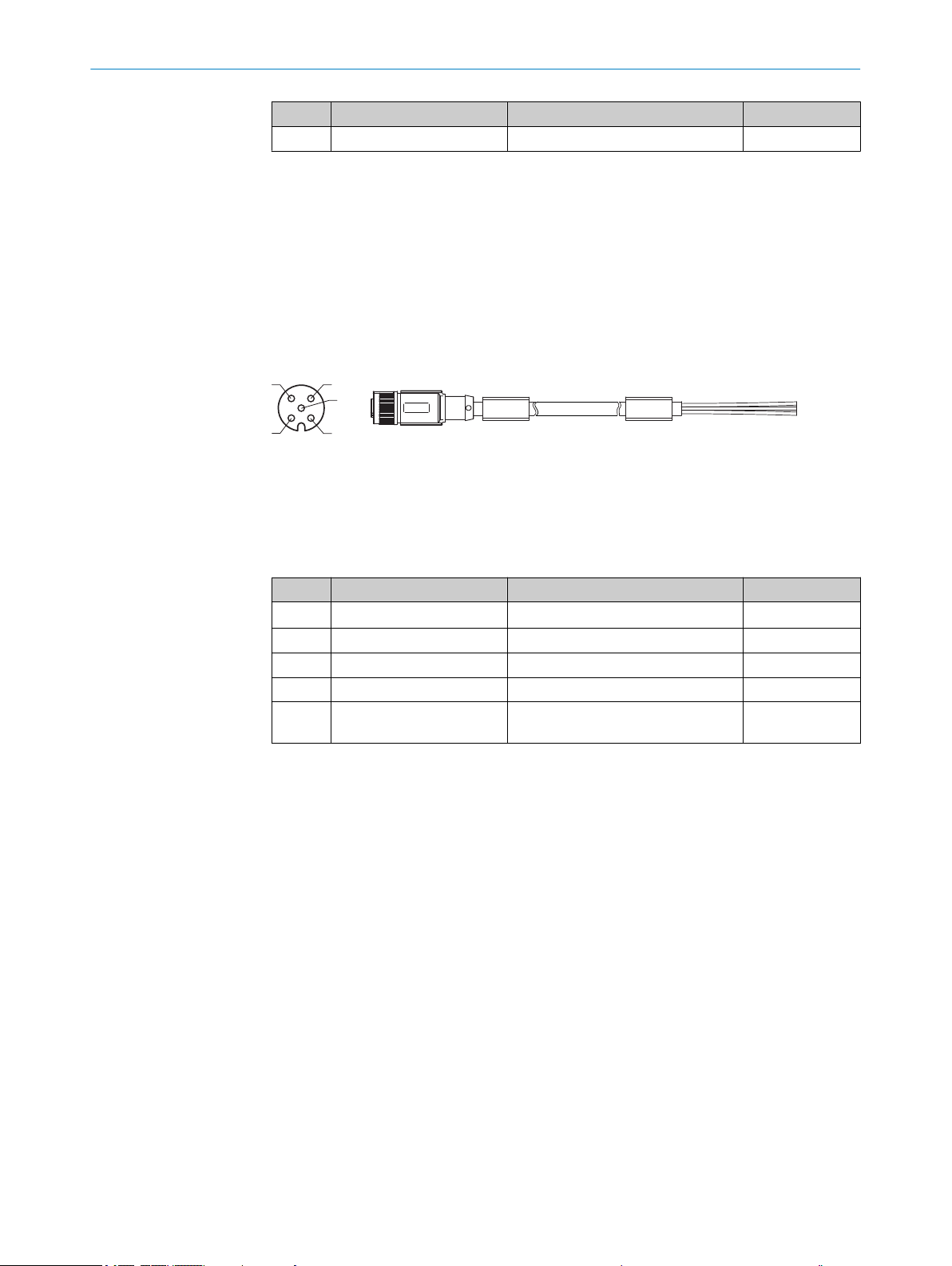
ð
1
43
5
2
1 2
APPENDIX 14
Pin Signal Function Wire color
5 – Not connected –
14.4.4 “Power/Switching input” connection to customer-specific connection equipment or control cabinet
Adapter cable
Part no. 2095618 (5 m), unshielded, suitable for drag chain, deep-freeze compatible
For CLV61x Dual Port (CLV61x-Dx52x), M12, 5-pin
Ambient temperature range:
For mobile installation: –25 °C to +80 °C, for fixed installation: –40 °C to +80 °C
Figure 36: Adapter cable, part no. 2095618 (5 m)
Female connector, M12, 5-pin, A-coded (view from front)
1
Illustration may differ
2
Table 22: Signal assignment of adapter cable with open end
Pin Signal Function Wire color
1 V
2 Reserved (Do not use.) White
3 GND Ground Blue
4 Reserved (Do not use.) Black
5 Sensor 1 Digital switching input for external
S
14.5 Notes on PROFINET
14.5.1 Basic information on PROFINET
SICK recommends familiarizing yourself with the basic information described in the
planning guidelines and commissioning guidelines of the PI user organization
(PROFIBUS & PROFINET International, homepage: www.profinet.com).
These guidelines can be found in the "Downloads" area at:
www.profibus.com
•
14.5.2 General notes on PROFINET wiring
The signal lines must be wrapped in pairs (twisted pairs) and comply with at least CAT5
in line with ISO/IEC 11801 Edition 2.0. Class D. The signal lines must also be shielded
and grounded.
Supply voltage Brown
Gray
reading cycle
8017842/ZOK7/2019-02-01 | SICK OP E RA T IN G I N ST R UC T IO N S | CLV61x DualPort (PROFINET)
Subject to change without notice
SICK recommends using components certified by PROFINET.
More detailed information can be found in the “PROFINET Cabling and Interconnection
Technology” Installation Guide.
You can find the document in the “Downloads” area at:
www.profibus.com
•
65
Page 66

14 APPENDIX
14.5.3 PROFINET Conformance Class
The device complies with PROFINET Conformance Class B (CC-B) and supports the
properties defined within.
Further information on the PROFINET Conformance Classes can be found in the docu‐
ment of the PI user organization (PROFIBUS and PROFINET International).
You can find the document in the “Downloads” area at:
www.profibus.com
•
14.5.4 General requirements on a switch suitable for PROFINET applications
For PROFINET Conformance Class B and C (CC-B / CC-C), a PROFINET-certified switch
which can be configured as a PROFINET device must be used.
For further information, refer to the commissioning guidelines of the PI “Installation
Guideline PROFINET Part 2: Network Components”.
You can find the document in the “Downloads” area under:
www.profibus.com
•
14.5.5 Notes on installing the SICK bar code scanner into a PROFINET network
For 1-port devices, these include:
LLDP (neighborhood detection)
•
I&M 0-4 (device identification)
•
Device exchange by topology check
•
16 bit digital “status word” for reading gate result
•
16 bit digital “control word” for controlling the device via PLC
•
Heartbeat (for checking communication)
•
GSD file for configuring the device using modules via the PLC
•
1)
1)
1)
1)
For 2-port devices, these include:
LLDP (neighborhood detection)
•
I&M 0-4 (device identification)
•
Device exchange by topology check
•
MRP (ring redundancy)
•
16 bit digital “status word” for reading gate result
•
16 bit digital “control word” for controlling the sensor via PLC
•
Heartbeat (for checking communication)
•
GSD file for configuring the sensor using modules via the PLC
•
1)
1)
1)
1)
1)
14.5.6 Behavior of the switching outputs of the bar code scanner with “Fieldbus input” reading cycle source
The digital outputs can be configured so that they can show information from other net‐
work participants (e.g. external output 1 = fieldbus input).
1)
Properties of the CC-B
66
O PE R AT I NG IN S TR U CT I ON S | CLV61x DualPort (PROFINET) 8017842/ZOK7/2019-02-01 | SICK
In the event that a fieldbus is interrupted, these outputs are no longer updated and
keep the last value that existed before the interruption.
After switching on the fieldbus (power-up), all digital outputs are set to their “passive”
values.
Status of digital outputs with output value behavior
IOPS = Bad Contain the last value before cancellation
Connection lost Contain the last value before cancellation
Subject to change without notice
Page 67

Status of digital outputs with output value behavior
Switching on the PROFINET network Values are initialized to “passive”
The reading cycle input can also be controlled by the fieldbus. If the fieldbus is inter‐
rupted, the reading cycle input is no longer updated. Reading results can get lost since
the reading cycle input keeps the last value from before the interruption.
After switching on the fieldbus (power-up), the reading cycle input is set to its “passive”
value.
14.6 Configuration of the device using command strings
As an alternative to the SOPAS ET configuration software, the device can also be config‐
ured, and functions can be triggered in the device, with command strings via all data
interfaces. The command strings can be displayed individually in the SOPAS ET configu‐
ration software.
NOTICE
Both the command strings and the SOPAS ET configuration software are based on a
command language that has direct access to the device command interpreter. This
command language must be used with care, as the commands sent to the device are
carried out immediately. Parameter values altered by commands are initially only active
in the current parameter set in the volatile working memory of the device. For perma‐
nent storage, the altered parameter set must be copied with a special command into
the permanent store, so that the alteration is not lost when the supply voltage is
switched off.
APPENDIX 14
14.7
Command strings for triggering the read pulse:
START: <STX>sMN mTCgateon<ETX>
b
STOP: <STX>sMN mTCgateoff<ETX>
b
If the commands are entered via the terminal emulator of the SOPAS ET configuration
software, both control characters <STX> and <ETX> are omitted.
Overview of command strings for the device on request.
Abbreviations used
CAN Controlled Area Network. Field bus log based on the CAN bus
CDB Connection Device Basic (connection box)
CDM Connection Device Modular (connection module)
CLV Code reader V-principle
CMC Connection Module Cloning
ID Identification
MAC Medium Access Control
MRP Media Redundancy Protocol
PN PROFINET
SOPAS ET SICK Open Portal for Application and Systems Engineering Tool (PC
PLC Programmable Logic Controller
SMART SICK Modular Advanced Recognition Technology
TCP/IP Transmission Control Protocol/Internet Protocol
software for Windows for configuration of SICK devices)
8017842/ZOK7/2019-02-01 | SICK OP E RA T IN G I N ST R UC T IO N S | CLV61x DualPort (PROFINET)
Subject to change without notice
67
Page 68

Further locations at www.sick.com
Australia
Phone +61 (3) 9457 0600
1800 33 48 02 – tollfree
E-Mail sales@sick.com.au
Austria
Phone +43 (0) 2236 62288-0
E-Mail office@sick.at
Belgium/Luxembourg
Phone +32 (0) 2 466 55 66
E-Mail info@sick.be
Brazil
Phone +55 11 3215-4900
E-Mail comercial@sick.com.br
Canada
Phone +1 905.771.1444
E-Mail cs.canada@sick.com
Czech Republic
Phone +420 2 57 91 18 50
E-Mail sick@sick.cz
Chile
Phone +56 (2) 2274 7430
E-Mail chile@sick.com
China
Phone +86 20 2882 3600
E-Mail info.china@sick.net.cn
Denmark
Phone +45 45 82 64 00
E-Mail sick@sick.dk
Finland
Phone +358-9-25 15 800
E-Mail sick@sick.fi
France
Phone +33 1 64 62 35 00
E-Mail info@sick.fr
Germany
Phone +49 (0) 2 11 53 01
E-Mail info@sick.de
Hong Kong
Phone +852 2153 6300
E-Mail ghk@sick.com.hk
Hungary
Phone +36 1 371 2680
E-Mail ertekesites@sick.hu
India
Phone +91-22-6119 8900
E-Mail info@sick-india.com
Israel
Phone +972-4-6881000
E-Mail info@sick-sensors.com
Italy
Phone +39 02 27 43 41
E-Mail info@sick.it
Japan
Phone +81 3 5309 2112
E-Mail support@sick.jp
Malaysia
Phone +603-8080 7425
E-Mail enquiry.my@sick.com
Mexico
Phone +52 (472) 748 9451
E-Mail mario.garcia@sick.com
Netherlands
Phone +31 (0) 30 229 25 44
E-Mail info@sick.nl
New Zealand
Phone +64 9 415 0459
0800 222 278 – tollfree
E-Mail sales@sick.co.nz
Norway
Phone +47 67 81 50 00
E-Mail sick@sick.no
Poland
Phone +48 22 539 41 00
E-Mail info@sick.pl
Romania
Phone +40 356-17 11 20
E-Mail office@sick.ro
Russia
Phone +7 495 283 09 90
E-Mail info@sick.ru
Singapore
Phone +65 6744 3732
E-Mail sales.gsg@sick.com
Slovakia
Phone +421 482 901 201
E-Mail mail@sick-sk.sk
Slovenia
Phone +386 591 78849
E-Mail office@sick.si
South Africa
Phone +27 (0)11 472 3733
E-Mail info@sickautomation.co.za
South Korea
Phone +82 2 786 6321
E-Mail info@sickkorea.net
Spain
Phone +34 93 480 31 00
E-Mail info@sick.es
Sweden
Phone +46 10 110 10 00
E-Mail info@sick.se
Switzerland
Phone +41 41 619 29 39
E-Mail contact@sick.ch
Taiwan
Phone +886-2-2375-6288
E-Mail sales@sick.com.tw
Thailand
Phone +66 2 645 0009
E-Mail marcom.th@sick.com
Turkey
Phone +90 (216) 528 50 00
E-Mail info@sick.com.tr
United Arab Emirates
Phone +971 (0) 4 88 65 878
E-Mail info@sick.ae
United Kingdom
Phone +44 (0)17278 31121
E-Mail info@sick.co.uk
USA
Phone +1 800.325.7425
E-Mail info@sick.com
Vietnam
Phone +65 6744 3732
E-Mail sales.gsg@sick.com
8017842/ZOK7/2019-02-01/en
SICK AG | Waldkirch | Germany | www.sick.com
 Loading...