

Page 1
Line scanner Raster scanner
β
OPERATING INSTRUCTIONS
en
CLV61x
Bar Code Scanner
CLV610-C0000 CAN Mid Range
CLV615-F2000 FIELDBUS Long Range
Intended Use
The CLV61x bar code scanner is an intelligent SICK 4Dpro
sensor and is used exclusively for automatic, stationary iden-
tication and decoding of bar codes on moving or stationary
objects. The data content of the decoded bar codes is sent
by the CLV61x to a superordinate computer for further processing. Depending on the model, this is either done directly
via a serial data interface (RS-232) or indirectly via the
SICK CAN sensor network on a coordinating device (e.g.,
master).
Correct use also includes compliance with all information in
these operating instructions as well as in the supplementary & “CLV61x Bar Code Scanner” Technical Information
(no. 8015592).
The product family CLV61x consists of the three series ECO,
CAN, and FIELDBUS (FIELDBUS in combination with the
optional CDF600-21xx eldbus module). Depending on the
model, the series offer the following options:
• Reading range variants (e.g., Short Range, Long Range)
• Line scanner or raster scanner
• Reading window on front or side
• Different connecting cable lengths
All devices have two serial data interfaces (HOST/AUX). The
CAN and FIELDBUS series also offer the SMART decoder for
identifying partly damaged or low-quality bar codes as well as
an additional CAN interface.
About This Document
The purpose of these operating instructions is to allow you
to put the CLV61x into operation quickly and easily and to
achieve initial read results as a stand-alone device.
The operating instructions describe the commissioning process for an application with a single CLV61x. This is done, for
example, using the device version CLV610-C0000 from the
CAN series and its default setting. The CDB620 connection
module, for example, is used for the industrial-standard signal
distribution of the CLV61x.
The operating instructions are valid for the following variants:
• CLV610-C0000 (CAN, Mid Range, line scanner, reading
window on front, SMART decoder)
• CLV615-F2000 (FIELDBUS, Long Range, line scanner,
reading window on side, CAN, SMART decoder)
In the following, the bar code scanner CLV61x is referred to in
simplied form as “CLV61x.”
Supplementary Documents
More detailed information about mounting and electrical installation as a stand-alone device is available in & “CLV61x
Bar Code Scanner” Technical Information (no. 8015592).
This document describes:
• Optional mounting accessories (brackets)
• The prevention of ground potential equalization currents in
applications with widely distributed systems
• Pin and lead color assignments of cables
• Electrical wiring plans for the CDB620 connection module
relating to the CLV61x
Operation of the CLV61x CAN in the SICK CAN Sensor
Network
The setup and wiring of the SICK-specic CAN network as well
as the integration of the CLV61x CAN and FIELDBUS series in
the network is described in the & SICK CAN Sensor Network
Operating Instructions.
Operation of the CLV61x FIELDBUS in PROFIBUS DP
The integration of the CLV61x FIELDBUS series in PROFI-
BUS DP via the CDF600-21xx eldbus module is described
in the & “CDF600-21xx Fieldbus Module PROFIBUS DP”
Operating Instructions (no. 8015335) and the supplementary
& “CDF600-21xx Fieldbus Module PROFIBUS DP” Technical
Information (no. 8015337).
Information about conguration can be found in the online
help function of the conguration software SOPAS ET.
The information can be accessed as a PDF on the CLV61x
product site on the web (www.sick.com/CLV61x).
Safety Information
• This chapter is about the safety of commissioning personnel, as well as operators of the system in which the CLV61x
is integrated.
• Read these operating instructions before starting any work
on the CLV61x in order to familiarize yourself with the
device and its functions. The operating instructions are
considered a part of the device and must be kept in an
accessible location in the immediate vicinity of the CLV61x
at all times!
• The CLV61x corresponds to laser class 2.
Laser warning notice see “Optical radiation: Laser class
2 Page 6”.
• Opening the screws of the CLV61x housing will invalidate
any warranty claims against SICK AG. For further warranty
provisions, see the General Terms and Conditions of SICK
AG, e.g., on the delivery note of the CLV61x.
Commissioning and Conguration
Scope of Delivery
• CLV61x in the ordered version (series, reading range, scanning method, reading window orientation)
• Accessories that can be optionally ordered such as e.g.
brackets
Step 1: Mounting
NOTE
Radio interference may occur when the CLV61x is used in
residential areas!
> The CLV61x must be used exclusively in industrial environ-
ments (EN 61000-6-4).
Equipment Required
• 2 x M5 screws for mounting the CLV61x on a mounting device (bracket). Screw length is dependent on the mounting
base (wall thickness of bracket). When using optional SICK
brackets, screws for the CLV61x are included.
Mounting Requirements
• The permitted ambient conditions for the operation of the
CLV61x must be complied with (e.g., temperature, radiated emission, ground potential see section “Technical
Specications (Excerpt) Page 5” and section “Risk of
injury/risk of damage via electrical current! Page 2”).
• The device must only be mounted using the pairs of
threaded mounting holes provided for this purpose.
• Stable mounting device with sufcient load-bearing capacity and suitable dimensions for the CLV61x.
Weight depends on model, max. 206 g (not including
cables). For dimension drawing, see section “Device
overview CLV61x” on page 3.
• Shock and vibration-free mounting.
• Clear view of the bar codes to be measured on the objects.
Mounting CLV61x
1. Select a suitable mounting location for the CLV61x with a
clear view of the object to be scanned. The mounting location and position depend on the respective reading range
of the CLV61x version. The available reading range is
dependent on the distance from the code and the required
resolution. The mounting location must therefore be cho-
sen whilst taking into account the respective reading eld
length and height, as well as resolution and depth of focus
( see section “Reading elds Page 5”).
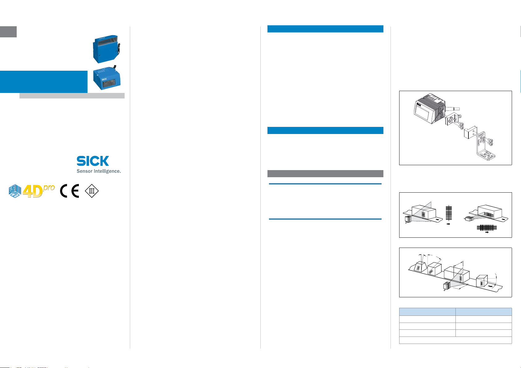
2. Mount the CLV61x on a bracket using both screws.
Mounting example: use of quick-clamping device (clamp bracket)
no. 2025526 in combination with the mounting bracket no. 2020410
3. Depending on the scanning method, roughly align the
CLV61x on the object with the bar code to be measured.
Allocation of scanning method to bar code and conveyor direction
α
Depth of
field
γ
Reading
distance
Possible read angle that could occur between scanning line and bar code
Angle Limit Value
Tilt a max. 30°
Pitch b max. 45°
Skew g max. 45°
*) depending on the module width
*)
8015589/ZNI9/2017-06-13 • Subject to errors and modications • © SICK AG • Waldkirch • Germany • www.sick.com CLV61X | SICK 1
Page 2
4. In order to avoid a total reection of the scanning line, tip
Line scanner
Line scanner
)(
CDB620
DC 10 V ... 30
the CLV61x with the following skew angle from the perpendicular to the bar code surface.
(front reading window)
(Top view
Avoid surface reection through correct arrangement
(lateral reading window)
105°105°
Top view)
Connection Module CDB620
> Mount the CDB620 connection module in the vicinity of
the CLV61x. Through the serial data interfaces (RS-232)
recommended cable length max. 5 m between both
devices. Mount the CDB620 in such a way that the device
can be accessed at all times. In relation to this, see &
“CDB620 Connection Module” Operating Instructions (no.
8012119).
Step 2: Electrical Connection
• The electrical installation must only be performed by
qualied electricians.
• The currently applicable safety regulations must be
observed when working in electrical systems!
• Electrical connections between the CLV61x and other de-
vices may only be created or xed when there is no power
to the system. Otherwise, the devices may be damaged.
• When using extension cables with open ends, ensure that
bare wire ends do not come into contact with each other
(risk of short-circuit when supply voltage is switched on!).
Wires must be appropriately insulated from each other.
• Wire cross sections of the supply cable from the customer's power system should be designed in accordance
with the applicable standards.
If the supply voltage for the CLV61x is not supplied via the
optional CDB620 connection module, the CLV61x must
be protected by a separate max. 2 A slow-blow fuse at the
beginning of the supply circuit.
• In order to retain the IP 65 enclosure rating for the CLV61x
connecting cable even when using an extension cable
(e.g., no. 6034417, 2 m/6.56 ft), insert rubber seal no.
4038847 between the plug and socket of the D-Sub plug
connection of the cables and screw in the plug connection.
• Circuits connected to the CLV61x must be designed as
SELV circuits (SELV = Safety Extra Low Voltage).
a DANGER
Risk of injury/risk of damage via electrical current!
The CLV61x is designed to be operated in a system with professional grounding of all connected devices and mounting
surfaces to the same ground potential.
Incorrect grounding of the CLV61x can, due to equipotential
bonding currents between the CLV61x and other grounded
devices in the system, place the metal housing under a dangerous voltage, cause malfunction and destruction of devices
as well as damage to the cable shielding through heating,
and thus cause cable res.
• Work on the electrical system must only be performed by
qualied electricians.
• Ensure ground potential at all grounding points.
n the event of damage to the cable insulation, immediately
• I
switch off the power supply and have the damage repaired.
> See the “Electrical Installation” chapter in the & “CLV61x
Bar Code Scanner” Technical Information (no. 8015592)
on the product site on the web (www.sick.com/CLV61x) for
measures to eliminate hazards.
1. Connect the 15-pin D-Sub-HD plug of the CLV61x cable to
the CDB620 connection module.
2. Connect a read pulse sensor, such as a photoelectric sen-
sor at the “Sens 1” switching input of the CDB620.
See the “Electrical Installation” chapter in the & “CLV61x
Bar Code Scanner” Technical Information (no. 8015592).
3. Connect the serial AUX interface (RS-232) of the CLV61x to
the PC (9-pin D-Sub plug) with a suitable data cable (e.g.,
no. 2014054, 2 m) using the internal plug “AUX” (9-pin
D-Sub) of the CDB620.
If the PC does not have an RS-232 interface, use a suitable adapter cable with RS-232 <> USB converter (e.g.,
no. 6042499, 1.5 m).
Connection
Module SOPASSOPAS
1
2
...
...
GND
V
11 10 12
V
s
Sens 1
SGND
Reading
clock
Electr. connection of the CLV61x for commissioning as a stand-alone device
Aux
SerialSerial
“HOST/AUX/I/O“
(RS-232)
“AUX“ (RS-232)
e.g. cable no. 2014054
(2 m)
CLV61x
Configuration
Diagnosis
4. Switch on the supply voltage for the CDB620 and the PC.
All LEDs on the CDB620 will light up briey.
The CLV61x starts with a delay and uses the default
parameters set in the factory for the initialization. After a
successful self-test, the LED on the CLV61x lights up blue
to indicate the “Device Ready” status.
Step 3: Conguration with PC
User Modes and Statuses of the CLV61x:
• Quick Start (initial commissioning for read operation)
• Read operation
• Percentage evaluation (for diagnostic purposes)
• Conguration via SOPAS ET conguration software
• Firmware download
Conguration
In case of error, the SOPAS ET conguration software is used
by default to adjust the CLV61x parameters to the application
and to the diagnostics.
Installing and Starting the Conguration Software
1. Download and install the SOPAS ET software on the PC
from the website “www.sick.com/software”. In this case,
select the “Complete” option as suggested by the install
wizard.
2. Start “Standard” user interface for standalone applica-
tions”.
3. Establish a connection between software and CLV61x e.g.,
via the serial AUX interface (57.6 kBd).
The connection wizard starts automatically. Under interface selection, select the standard protocol.
4. Select the CLV61x from the devices that are now available
and displayed. The
Quick Start device page appears.
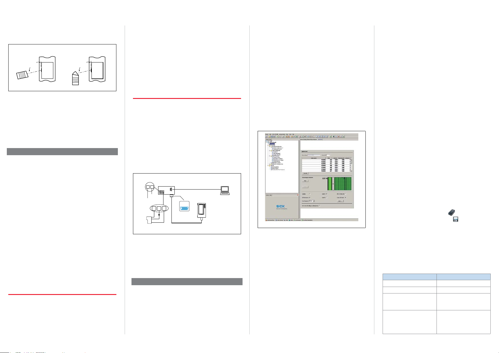
SOPAS ET Program Window
Device tree (left), device page Quick Start (right)
User Level, Parameter Download
The user is automatically logged onto the CLV61x at user
level “Authorized Client” (password: client). The user can
change parameters, which will be immediately transferred to
the CLV61x (default). Initially they will have only temporary
effect there, without being saved, until the supply voltage is
switched off. If the parameters are to be retained, they must
be permanently saved ( see section “c. Completing the
Conguration Page 2”).
a. Conguration via the “Quickstart” Device Page
The “Quickstart” device page offers an overview of the most
important parameters and enables quick evaluation of code
content. Functions such as “Evaluation Window,” “Percentage
Evaluation,” “Code Conguration,” and “Scanning Frequency”
are available via the Quickstart.
Evaluation Window
The evaluation window shows the code content, the code
type, the increment index, the code security, and the device
number of the reading CLV61x.
Percentage Evaluation
The percentage evaluation permanently assesses the quality
of the reading. Bar codes are not assessed. Here, the bar
codes must not be subjected to any conveying movement.
The CLV61x performs 100 scans in each case and evaluates
the reading quality. The CLV61x continuously emits read
results every 2 s via the AUX interface, together with the read
diagnostic data.
Code Conguration
In the factory default setting, the CLV61x decodes the following code types:
• Code 39
• Interleaved 2 of 5
• Code 128 family
To activate or deactivate further code types:
Device tree > Parameters > Code conguration.
b. Summary of Further Useful Adaptation Options
Object Trigger Control
The CLV61x can, as described in the standard application,
be operated with a connected read pulse sensor, such as a
photoelectric sensor on the “Sensor 1” switching input. To
select a different pulse type or switching input:
Device tree > Parameters > Object trigger control.
c. Completing the Conguration
> Permanently save the entire conguration:
Parameter set in CLV61x: click the
Conguration le on the PC: click the
Important!
In order to commission the CLV61x CAN or FIELDBUS series
in the SICK CAN scanner network together with further SICK
products, select the “Advanced” user interface when starting
the conguration software program. Path: Start > Programs >
SICK > SOPAS ET Engineering Tool > SOPAS.
The “Standard” user interface option is not suitable for this.
Default Setting CLV61x (Summary)
Parameter Value
Scanning frequency 500 Hz
Laser timeout No
Code length
Reading trigger
button
button.
Free
(max. 1,500 characters in reading interval across all measured
codes)
Read operation:
Start: Sensor 1 switching input
Stop: Sensor 1 switching input
Quick Start:
START and STOP buttons for
percentage evaluation
CLV61X | SICK 8015589/ZNI9/2017-06-13 •Subject to errors and modications • © SICK AG • Waldkirch • Germany • www.sick.com2
Page 3

LED
Parameter Value
38.5
22.5
(0.89)
65.9 (2.59)
Host interface
57.6 kBd, 8, n, 1,
Output format: 1
AUX interface Output format: read diagnosis
Switching outputs
Password protection for
parameters
Result 1: Device Ready
Result 2: Good Read
No
Step 4: Fine Adjustment
1. Align the CLV61x so that the angle between the scanning
line and the bar code stripes is almost 90°.
2. Manually guide objects with bar codes successively into
the reading eld of the CLV61x in a realistic manner and
check the reading result. If objects are only guided in an
unstructured manner, it may be necessary to check several
different positions of the bar codes. Here, it must be
ensured that the limit values of the permitted read angles
are not exceeded.
3. Adjust the CLV61x so that the good read rate is 100%.
Description of the Device
Device overview CLV61x
Reading window on front
19.5 (0.77)
13.7 (0.54)
50°
(1.52)
37.9
61 (2.4)
Ready
G Read
N Read
HW Err
UserDef1
0.2
0.2
22.5
5.7
(0.89)
(0.01)
(0.01)
(0.22)
17.1 (0.67)
10 (0.39)
6.2
(0.24)
41.8 (1.65)
(1.94)
19.5
(0.77)
65.9 (2.59)
35.6
(1.4)
(25.4)
(1)
(1)
(27.4)
38.5
(1.52)
Legend:
1 2 x threaded mounting hole M5, 5 mm deep for mounting the
CLV61x
2 Internal impact point: rotation point of the variable direction laser
beam
3 Central position of the deected laser beam in the V-shaped aper-
ture angle
4 Cable outlet, standard cable 0.9 m/2.95 ft (+10%) with 15-pin D-
Sub-HD plug
5 Reading window
6 Status display (1 x RGB-LED) with signal color allocation
7 Reference point for reading distance (housing edge) from CLV61x to
object
Optical Status Indicators
Ready
G Read
N Read
HW Err
UserDef1
Signal
colors
Reading window on side
14.9
(0.59)
2
(.08)
10
(0.39)
0.2
0.2
(0.01)
(0.01)
59.4 (2.34)
79.9 (3.14)
105°
Ready
G Read
N Read
HW Err
UserDef1
22.5 (0.89)
50°
5.7
5.7
(0.22)
(0.22)
10
10
(0.39)
(0.39)
37.9 (1.49)
All length measures in mm (inch)
60.4 (2.38)
35.6
(1.4)
38.5
(1.52)
All length measures in mm (inch)
23.8
(0.94)
16.4 (0.64)
27.4
60.5 (2.38)
2.7
(1.08)
(0.11)
Indicator colors and behavior of LED status display
Indicator Color of LED Status
Lights up constantly after switching on
Blue
Ready
O
– –
G Read
N Read
HW Err
Further
indicators
O = lights up constantly or once briey
= ashes, = ashes alternately
O
O
O
O
and completion of successful self-test.
Goes out when downloading conguration data from the CLV61x
Green Lights up briey after Good Read
Red Lights up briey after No Read
Lights up constantly in case of
Red
hardware error
Red
Firmware download:
Blue
Indicator ashes alternately
Firmware download:
Red
Lights up constantly in case of error
8015589/ZNI9/2017-06-13 • Subject to errors and modications • © SICK AG • Waldkirch • Germany • www.sick.com CLV61X | SICK 3
Page 4

Overview of all interfaces and connection options for CLV61x ECO/CAN
In
(e.g. incr
Te
In
(e.g.
Output
(e.g. indicat
Output
(e.g. indicat
CDB620
Configuration
PC
DC 10 ... 30
Switching inputs/outputs = digital
Configuration
PC
DC 10 ... 30
CAN Sensor Network
CDF600-21xx
In
(e.g.
Result 1 (switching output)
Result 2 (switching output)
SerialSerial
e.g. cable no. 2014054 (2 m/6.56 ft)
SerialSerial
“HOST (RS-232)/
AUX (RS-232)/
CLV61x ECO/CAN
I/O”
“HOST” (RS-232)
“CAN” (CLV61x CAN only)
“AUX” (RS-232)
V
put 1
external reading clock)
put 2
emental encoder,
ach-in matchcode)
1
or lamp)
2
or lamp)
1
2
GND
DC 10 ... 30 V
Connection module
...
...
Overview of all interfaces and connection options for CLV61x FIELDBUS
V
put 1
external reading clock)
CLV61 FIELDBUS
CAN/DC 10...30 V”
“AUX (RS-232)/
PROFIBUS
Fieldbus module
PROFIBUS PROFIBUS
Reading result
CAN Sensor Network
“AUX” (USB)
e.g. cable
no. 6036106
(2 m/6.56 ft)
Reading result
Diagnosis
Further data
processing
SOPASSOPAS
Diagnosis
Further data
processing
PLC
SOPASSOPAS
HOST
Overview of pin assignment
CLV61x ECO
15-pin D-Sub HD plug
6
1
11
N.C. = not connected
CLV61x CAN / FIELDBUS
15-pin D-Sub HD plug
10
5
15
1
DC 10 ... 30 V
2
RxD (RS-232), AUX
3
TxD (RS-232), AUX
4
Sensor 2 (switching input)
5
GND
6
N.C.
7
RxD (RS-232), HOST
8
N.C.
9
TxD (RS-232), HOST
10
N.C.
11
N.C.
12
Result 1 (switching output)
13
Result 2 (switching output)
14
Sensor 1 (switching input)
15
SensGND
10
6
5
1
15
11
1
DC 10 ... 30 V
2
RxD (RS-232), AUX
3
TxD (RS-232), AUX
4
Sensor 2 (switching input)
5
GND
6
N.C.
7
RxD (RS-232), HOST
8
N.C.
9
TxD (RS-232), HOST
10
CAN_H
11
CAN_L
12
13
14
Sensor 1 (switching input)
15
SensGND
8015589/ZNI9/2017-06-13 • Subject to errors and modications • © SICK AG • Waldkirch • Germany • www.sick.com CLV61X | SICK 4
Page 5

Reading elds
(15.75)
(-5.91)
(-3.94)
(-7.87)
(-1.97)
Reading field height in mm (inch)
(13.78)
(-5.91)
(-3.94)
(-1.97)
Reading field height in mm (inch)
CLV610: Mid Range, reading window on front
200
(7.87)
150
(5.91)
100
50
(1.97)
0
-50
-100
-150
-200
0 100 200 300 400
CLV615: Long Range, reading window on side
150
(5.91)
100
(3.94)
50
(1.97)
0
-50
-100
-150
050 100 150 200 250 300 350
(3.94)
Resolution
a: 0.2 mm (7.9 mil)
c: 0.50 mm (19.7 mil)
(1.97)
(3.94)
Resolution
b: 0.35 mm (13.8 mil)
a
b
c
d
(7.87) (11.81)
Reading distance in mm (inch)
b: 0.35 mm (11.8 mil)
d: 1.00 mm (39.5 mil)
b
c
(5.91) (7.87) (9.84) (11.81)
Reading distance in mm (inch)
c: 0.50 mm (19.7 mil)
Acoustic Status Indicator (Beeper)
Depending on the user mode of the CLV61x, the beeper uses
different melodies or single tones to indicate the following
results:
• Fulllment/non-fulllment of a congured condition in read
operation (e.g., Good Read)
• The completion of device functions triggered by the user or
ended by quitting (conrmation of operation steps)
• Completion of functions (positive/negative conrmation)
User Mode Function/Sound
Switching on
Read operation
Percentage
Evaluation
Conguration
Firmware
download
*) Allocation, e.g., via conguration software SOPAS ET
Beeper Default Setting:
Switched on, volume: quiet, read operation: output condition
“Good Read”.
Successful self-test and start of read operation:
melody
Conrmation of Good Read in default setting:
a tone.
Adjustable event condition*)
Start: melody
100 scans per read: a tone
End: melody
Parameter download to CLV61x:
Start: melody, successful completion: melody
Parameter upload from CLV61x: no sound
Firmware:
Start: a tone, successful completion: a tone
Reboot CLV61x:
Successful completion: melody
Loading the sdd le to the CLV61x:
Successful completion: melody
Technical Specications (Excerpt)
Models CLV610-C0000 (no. 1057125)
Series CLV610-C0000: CAN
Scanning method Line scanner
Reading window CLV610-C0000: on front
Reading range/
Code resolution
Code types All current 1D code types
Focus Fixed focus
Scanning frequency 400 Hz ... 1,000 Hz
Light source Visible red light (655 nm)
Laser class Class 2 according to EN/IEC 60825-1:2014
Ambient light
compatibility
Optical indicators 1 RGB-LED, multi-colored
Acoustic indicators Beeper, can be deactivated, can be allocated
Host interface Serial (RS-232), 2.4 kBd... 115.2 kBd
AUX interface Serial (RS-232), 57.6 kBd (xed)
CAN interface CAN sensor network
Fieldbus connection CLV615-F2000 only:
Switching inputs 2 x physical, 2 x additional external via
Switching outputs 2 x physical, 2 x additional external via
Electrical
connection
Supply voltage DC 10 V ... 30 V, SELV in accordance with IEC
Power consumption Typically 2.8 W
Housing (color)/
reading window
2)
Weight
Electrical safety EN 60950-1: 2011-01
Protection class III (VDE 016 / IEC 10110-1)
Enclosure rating IP 65 (DIN 40 050)
EMC Radiated emission:
Vibration resistance
Shock resistance
Ambient temperature
Permissible relative
air humidity
1) With switching outputs without load
2) Without connecting cable and plug
CLV615-F2000 (no. 1058334)
CLV615-F2000: FIELDBUS
CLV615-F2000: on side
CLV610: Mid range/ 0.2 mm ... 1.0 mm
CLV615: Long range/ 0.35 ... 1.0 mm
(identical to EN/IEC 60825-1:2007)
Complies with 21 CFR 1040.10 except for
the tolerance according to Laser Notice No.
50 from June 24, 2007 and its followers.
2,000 lx (on bar code)
function for event signaling
20 kBit/s ... 1 MBit/s
Via serial interface to external CDF600-21xx
eldbus module (PROFIBUS DP)
optional CMC600 module
= max. 30 V, Iin= max. 5 mA
V
in
Opto-decoupled, reverse polarity protected
optional CMC600 module
= VS– 1.5 V, I
V
out
Short-circuit protected, temperature
protected
Standard cable 0.9 m/2.95 ft (+10%) with
15-pin D-Sub-HD plug
6034-4-41: 2005. Reverse polarity protected
Aluminum die casting (RAL 5012)/
Glass (optionally plastic)
181 g (with reading window on front)
206 g (with reading window on side)
EN 61000-6-4: 2007-01 + A1: 2011
Electromagnetic immunity:
EN 61000-6-2: 2005-08
EN 60068-2-6: 2008-02
EN 60068-2-27: 2009-05
Operation: 0°C ... +40°C
Storage: –20°C ... +70°C
90%, non-condensing
≤ 100 mA.
out
1)
CLV61X | SICK 8015589/ZNI9/2017-06-13 •Subject to errors and modications • © SICK AG • Waldkirch • Germany • www.sick.com5
Page 6

For detailed technical specications, see the
Housing with
fr
windo
Housing with
Online Data Sheet on the product site on the web
(www.sick.com/CLV61x).
Warnings
a CAUTION
Optical radiation: Laser class 2
The CLV61x uses a red laser diode and corresponds to laser
class 2.
The entire reading window is a laser output aperture.
ont reading
w
Outlet opening for the laser radiation on the reading window of the
CLV61x
The human eye is not at risk when briey exposed to the
radiation for up to 0.25 seconds. Exposure to the laser beam
for longer periods of time may cause damage to the retina.
The laser radiation is harmless to human skin.
> Do not look into the laser beam intentionally.
> Never point the laser beam at people’s eyes.
> If it is not possible to avoid looking directly into the laser
beam, e.g., during commissioning and maintenance work,
suitable eye protection must be worn.
> Avoid laser beam reections caused by reective surfaces.
Be particularly careful during mounting and alignment
work.
> Do not open the housing. Opening the housing will not
switch off the laser. Opening the housing may increase the
level of risk.
> Current national regulations regarding laser protection
must be observed.
Incorrect use can lead to the user being exposed to dangerous radiation.
Important!
Maintenance is not necessary to ensure compliance with
laser class 2.
lateral reading
window
CLV610-C0000
D-79276 Reute
Made in Germany
Installation site and design of the combination of black and yellow laser
warning label and type label with laser performance data.
P/N: 1057125
S/N: 1540 0001
DC 10...30V
2.8W Imax=700mA
Pmax=1.5mW
Manufactured: October 2015
= 655nmλ
P<1.0mW average
Pulse duration <300µs
Meaning of the laser warning label: laser radiation -
Do not look into the laser beam - laser class 2
Controlling the Laser Diode
In real operation (triggered read mode), the CLV61x switches
the laser diode on and off again with the trigger signals of the
conveyor system (object in reading range). Triggering occurs
here via the switching inputs of the CLV61x or by a command
via one of the data interfaces.
A laser timeout congured with SOPAS ET (device page
illumination control) can be used to automatically switch
off the laser diode for this type of object trigger control if the
pulse has stopped for too long (e.g., conveyor system has
stopped). If the function is activated, the laser timeout is
10 min (default). The current internal reading interval of the
CLV61x remains open.
The laser diode is permanently or repeatedly switched on in
the following device statuses:
• In the “Percentage Evaluation” and “Auto Setup” user
modes (only used temporarily for conguration or diagnosis)
• In reading operation in the pulsing types “Auto cycle”
(adjustable pulse/pause ratio) or “free.”
If timeout is activated, it will have no effect here.
Important!
The CLV61x has no optical indicator (LED) for laser diode
activity.
Maintenance and Care
The CLV61x operates without the need for maintenance, except for cleaning the reading window if it gets contaminated.
> In order to obtain maximum reading performance from
the CLV61x, the reading window must be checked for contamination at regular intervals (e.g., weekly). This applies
especially when using the CLV61x in harsh environments
(dust, abrasion, moisture, etc.).
For reading, the reading window has to be generally clean
and dry.
Cleaning the Reading Window
The type of screen material used in the reading window can
be found on the type label of the device:
CLV61x-xxxxy
• y = 0: Glass
• y = 1: Plastic
NOTE
Damage to the Reading Window!
Reduced reading performance due to scratches or streaks
on the reading window.
> Do NOT use any aggressive cleaning agents with powder
additives (increased abrasion) or agents e.g., acetone for
cleaning.
> Avoid any movements that could cause scratches or abra-
sions on the reading window.
1. Switch off the device for the duration of the cleaning (laser
protection!) or if this is not possible, wear laser protection
goggles, which absorb the wavelength used and effectively
prevent damage to the eyes.
2. Remove dust from the reading window (glass) using a soft
clean brush.
Plastic reading windows must only be wet-cleaned!
3. Clean the reading window (plastic /additionally for glass
if required) with a clean, soft, damp cloth (mild, anti-static
cleaning agent).
Important!
If the reading window is scratched or damaged (cracked,
broken), the window must be replaced by SICK service personnel. Contact SICK Service to arrange this.
Static charge causes dust particles to adhere to the reading
window. This effect can be avoided by using the SICK antistatic plastic cleaner (no. 5600006) in combination with the
SICK lens cloth (no. 4003353).
Transport and Storage
The CLV61x must be transported and stored in its original
packaging. The device must not be stored in airtight containers, so that any residual moisture is able to escape.
Storage conditions: dry, dust-free. no direct sunlight, –20 °C
... +70°C, relative air humidity max. 90% (non-condensing).
Repairs
Repair work on the CLV61x may only be performed by quali-
ed and authorized service personnel from SICK AG.
Disassembly and Disposal
Any CLV61x which can no longer be used must be disposed of
in an environmentally friendly manner in accordance with the
respective applicable country-specic waste disposal regula-
tions. The CLV61x is electronic waste and must under no
circumstances be disposed of with general waste! SICK
AG is not currently able to take back devices that can no
longer be used.
Sources for Obtaining Additional Information
Additional information about the CLV61x and its optional
accessories can be found on the following online product
page:
CLV61x
www.sick.com/CLV61x
• Ordering information
• Operating instructions in German (no. 8015588) and
English (no. 8015589), in other languages if applicable
• Technical information for CLV61x bar code scanners in
German (no. 8015591) and English (no. 8015592)
• EC Declaration of Conformity
• Detailed technical specications (online data sheet)
• Dimensional drawing and 3D CAD dimension models in
various electronic formats
• SOPAS ET conguration software with online help
• Information about suitable accessories (e.g. cables,
mouting brackets, trigger sensors)
• Publications dealing with accessories
Integration of CLV61x FIELDBUS in PROFIBUS DP
www.sick.com/CDF600-2
• CDF600-21xx PROFIBUS DP eldbus module operating
instructions in German (no. 8015334) and English
(no. 8015335)
• Technical information for CDF600-21xx PROFIBUS
DP eldbus module (no. 8015336) and English
(no. 8015337)
Documents on Request
• Overview of command strings for CLV61x
Support is also available from your sales partner:
www.sick.com/worldwide
8015589/ZNI9/2017-06-13 ∙ MT_8M ∙ Printed in Germany
8015589/ZNI9/2017-06-13 • Subject to errors and modications • © SICK AG • Waldkirch • Germany • www.sick.com CLV61X | SICK 6
 Loading...