

Page 1
CLV60x
Bar code scanners
O P E R A T I N G I N S T R U C T I O N S
Page 2

Described product
CLV60x
Manufacturer
SICK AG
Erwin-Sick-Str. 1
79183 Waldkirch
Germany
Legal information
This work is protected by copyright. Any rights derived from the copyright shall be
reserved for SICK AG. Reproduction of this document or parts of this document is only
permissible within the limits of the legal determination of Copyright Law. Any modifica‐
tion, abridgment or translation of this document is prohibited without the express writ‐
ten permission of SICK AG.
The trademarks stated in this document are the property of their respective owner.
© SICK AG. All rights reserved.
Original document
This document is an original document of SICK AG.
2
O PE R AT I NG IN S TR U CT I ON S | CLV60x 8021817/10Y9/2018-09-14 | SICK
Subject to change without notice
Page 3

Contents
CONTENTS
1 About this document........................................................................ 5
1.1 Information on the operating instructions.............................................. 5
1.2 Explanation of symbols............................................................................ 5
1.3 Further information................................................................................... 6
2 Safety information............................................................................ 7
2.1 Intended use............................................................................................. 7
2.2 Improper use............................................................................................. 7
2.3 IP technology............................................................................................. 7
2.4 Limitation of liability................................................................................. 8
2.5 Modifications and conversions................................................................ 8
2.6 Requirements for skilled persons and operating personnel.................. 8
2.7 Operational safety and particular hazards.............................................. 9
3 Product description........................................................................... 10
3.1 Scope of delivery....................................................................................... 10
3.2 Type code.................................................................................................. 10
3.3 Type label.................................................................................................. 10
3.4 Status indicators....................................................................................... 11
3.5 Product features and functions (overview)............................................. 12
3.6 Operating principle................................................................................... 12
3.6.1 Object trigger control............................................................... 13
3.7 Reading operation mode.......................................................................... 13
4 Transport and storage....................................................................... 15
4.1 Transport................................................................................................... 15
4.2 Unpacking.................................................................................................. 15
4.3 Transport inspection................................................................................. 15
4.4 Storage...................................................................................................... 15
5 Mounting............................................................................................. 16
5.1 Overview of mounting procedure............................................................. 16
5.2 Mounting instructions............................................................................... 16
5.3 Mounting location..................................................................................... 16
5.3.1 Basic alignment of the scan line to the bar code.................. 16
5.3.2 Reading distance to the bar code and aperture angle α...... 17
5.3.3 Angle alignment of the device................................................. 17
5.3.4 Avoidance of surface reflections............................................ 17
5.3.5 Counting direction of the reading angle and the code angle 18
5.4 Mounting the device................................................................................. 18
6 Electrical installation........................................................................ 20
6.1 Safety......................................................................................................... 20
6.1.1 Notes on the electrical installation......................................... 20
6.2 Prerequisites for safe operation of the device........................................ 20
8021817/10Y9/2018-09-14 | SICK O PE R AT I NG IN S TR U CT I ON S | CLV60x
Subject to change without notice
3
Page 4

CONTENTS
6.3 Interface description................................................................................ 23
6.4 Wiring interfaces....................................................................................... 24
6.4.1 Connecting the supply voltage................................................ 24
6.4.2 Wiring the data interface......................................................... 25
6.4.3 Wiring digital switching inputs................................................ 25
6.4.4 Wiring digital switching outputs.............................................. 26
7 Commissioning.................................................................................. 28
7.1 Overview of the commissioning steps..................................................... 28
7.2 SOPAS ET configuration software............................................................ 28
7.3 Initial Commissioning............................................................................... 28
7.4 Fine adjustment and further configuration............................................. 28
8 Operation............................................................................................ 30
8.1 Operating options..................................................................................... 30
9 Maintenance...................................................................................... 31
9.1 Maintenance............................................................................................. 31
9.2 Cleaning..................................................................................................... 31
10 Troubleshooting................................................................................. 33
10.1 Overview of possible errors and faults.................................................... 33
10.2 Detailed fault analysis.............................................................................. 33
10.2.1 LEDs on the device.................................................................. 33
10.2.2 System information.................................................................. 33
10.3 Status log.................................................................................................. 33
10.3.1 Displaying the status log......................................................... 34
10.4 Repairs...................................................................................................... 34
10.5 Returns...................................................................................................... 34
10.6 Disposal..................................................................................................... 34
11 Technical data.................................................................................... 35
11.1 Features.................................................................................................... 35
11.2 Performance............................................................................................. 36
11.3 Interfaces.................................................................................................. 37
11.4 Mechanics/electronics............................................................................. 37
11.5 Ambient data............................................................................................. 39
12 Annex.................................................................................................. 41
12.1 EU declaration of conformity / Certificates............................................. 41
12.2 Certification according to UL62368........................................................ 41
12.3 Licenses.................................................................................................... 41
4
O PE R AT I NG IN S TR U CT I ON S | CLV60x 8021817/10Y9/2018-09-14 | SICK
Subject to change without notice
Page 5
1 About this document
1.1 Information on the operating instructions
These operating instructions provide important information on how to use devices from
SICK AG.
Prerequisites for safe work are:
Compliance with all safety notes and handling instructions supplied.
•
Compliance with local work safety regulations and general safety regulations for
•
device applications
The operating instructions are intended to be used by qualified personnel and electrical
specialists.
NOTE
Read these operating instructions carefully before starting any work on the device, in
order to familiarize yourself with the device and its functions.
The instructions constitute an integral part of the product and are to be stored in the
immediate vicinity of the device so they remain accessible to staff at all times. Should
the device be passed on to a third party, these operating instructions should be handed
over with it.
ABOUT THIS DOCUMENT 1
These operating instructions do not provide information on operating the machine or
system in which the device is integrated. For information about this, refer to the operat‐
ing instructions of the specific machine.
1.2 Explanation of symbols
Warnings and important information in this document are labeled with symbols. The
warnings are introduced by signal words that indicate the extent of the danger. These
warnings must be observed at all times and care must be taken to avoid accidents, per‐
sonal injury, and material damage.
DANGER
… indicates a situation of imminent danger, which will lead to a fatality or serious
injuries if not prevented.
WARNING
… indicates a potentially dangerous situation, which may lead to a fatality or serious
injuries if not prevented.
CAUTION
… indicates a potentially dangerous situation, which may lead to minor/slight injuries if
not prevented.
NOTICE
… indicates a potentially harmful situation, which may lead to material damage if not
prevented.
NOTE
… highlights useful tips and recommendations as well as information for efficient and
trouble-free operation.
8021817/10Y9/2018-09-14 | SICK O PE R AT I NG IN S TR U CT I ON S | CLV60x
Subject to change without notice
5
Page 6

1 ABOUT THIS DOCUMENT
1.3 Further information
NOTE
Further documentation for the device can be found on the online product page at:
www.sick.com/CLV60x
•
The following information is available for download there:
Model-specific online data sheets for device variants, containing technical data,
•
dimensional drawing, and specification diagrams
EU declaration of conformity for the product family
•
Dimensional drawings and 3D CAD dimension models in various electronic for‐
•
mats
These operating instructions, available in English and German, and in other lan‐
•
guages if necessary
Other publications related to the devices described here
•
Publications dealing with accessories
•
6
O PE R AT I NG IN S TR U CT I ON S | CLV60x 8021817/10Y9/2018-09-14 | SICK
Subject to change without notice
Page 7
2 Safety information
2.1 Intended use
The CLV60x bar code scanner is an intelligent, opto-electronic ID sensor and is used for
automatic, fixed identification and decoding of bar codes on moving or stationary
objects. The data content of the decoded bar codes is transmitted via the device to a
higher-level control (PLC) or an industrial computer for coordinating processing.
NOTE
The bar codes to be read must comply at least with quality level C in accordance with
ISO/IEC 15416.
The product variants with connecting cable and USB plug are not designed for rough
industrial environments with strong electromagnetic interference. During installation,
make sure that no sources of interference are in the direct vicinity of the product. Use
the USB devices in offices or in applications with similar ambient conditions (e.g.
libraries or laboratories).
SICK AG assumes no liability for losses or damage arising from the use of the product,
either directly or indirectly. This applies in particular to use of the product that does not
conform to its intended purpose and is not described in this documentation.
SAFETY INFORMATION 2
2.2 Improper use
Any use outside of the stated areas, in particular use outside of the technical specifica‐
tions and the requirements for intended use, will be deemed to be incorrect use.
•
•
•
WARNING
Danger due to improper use!
Any improper use can result in dangerous situations.
Therefore, observe the following information:
■
■
2.3 IP technology
NOTE
SICK uses standard IP technology in its products. The emphasis is placed on availability
of products and services.
SICK always assumes the following prerequisites:
The device does not constitute a safety component in accordance with the respec‐
tive applicable safety standards for machines.
The device must not be used in explosion-hazardous areas, in corrosive environ‐
ments or under extreme environmental conditions.
Any use of accessories not specifically approved by SICK AG is at your own risk.
Device should be used only in accordance with its intended use.
All information in these operating instructions must be strictly observed.
The customer ensures the integrity and confidentiality of the data and rights
•
affected by its own use of the aforementioned products.
In all cases, the customer implements the appropriate security measures, such as
•
network separation, firewalls, virus protection, and patch management.
8021817/10Y9/2018-09-14 | SICK O PE R AT I NG IN S TR U CT I ON S | CLV60x
Subject to change without notice
7
Page 8
2 SAFETY INFORMATION
2.4 Limitation of liability
Applicable standards and regulations, the latest state of technological development,
and our many years of knowledge and experience have all been taken into account
when assembling the data and information contained in these operating instructions.
The manufacturer accepts no liability for damage caused by:
■
Failing to observe the operating instructions
■
Incorrect use
■
Use by untrained personnel
■
Unauthorized conversions
■
Technical modifications
■
Use of unauthorized spare parts, consumables, and accessories
With special variants, where optional extras have been ordered, or owing to the latest
technical changes, the actual scope of delivery may vary from the features and illustra‐
tions shown here.
2.5 Modifications and conversions
NOTICE
Modifications and conversions to the device may result in unforeseeable dangers.
2.6
Interrupting or modifying the device or SICK software will invalidate any warranty claims
against SICK AG. This applies in particular to opening the housing, even as part of
mounting and electrical installation.
Requirements for skilled persons and operating personnel
WARNING
Risk of injury due to insufficient training.
Improper handling of the device may result in considerable personal injury and material
damage.
■
All work must only ever be carried out by the stipulated persons.
The operating instructions state the following qualification requirements for the various
areas of work:
■
Instructed personnel have been briefed by the operator about the tasks assigned
to them and about potential dangers arising from improper action.
■
Skilled personnel have the specialist training, skills, and experience, as well as
knowledge of the relevant regulations, to be able to perform tasks delegated to
them and to detect and avoid any potential dangers independently.
■
Electricians have the specialist training, skills, and experience, as well as knowl‐
edge of the relevant standards and provisions to be able to carry out work on elec‐
trical systems and to detect and avoid any potential dangers independently. In Ger‐
many, electricians must meet the specifications of the BGV A3 Work Safety Regu‐
lations (e.g. Master Electrician). Other relevant regulations applicable in other
countries must be observed.
The following qualifications are required for various activities:
8
O PE R AT I NG IN S TR U CT I ON S | CLV60x 8021817/10Y9/2018-09-14 | SICK
Subject to change without notice
Page 9
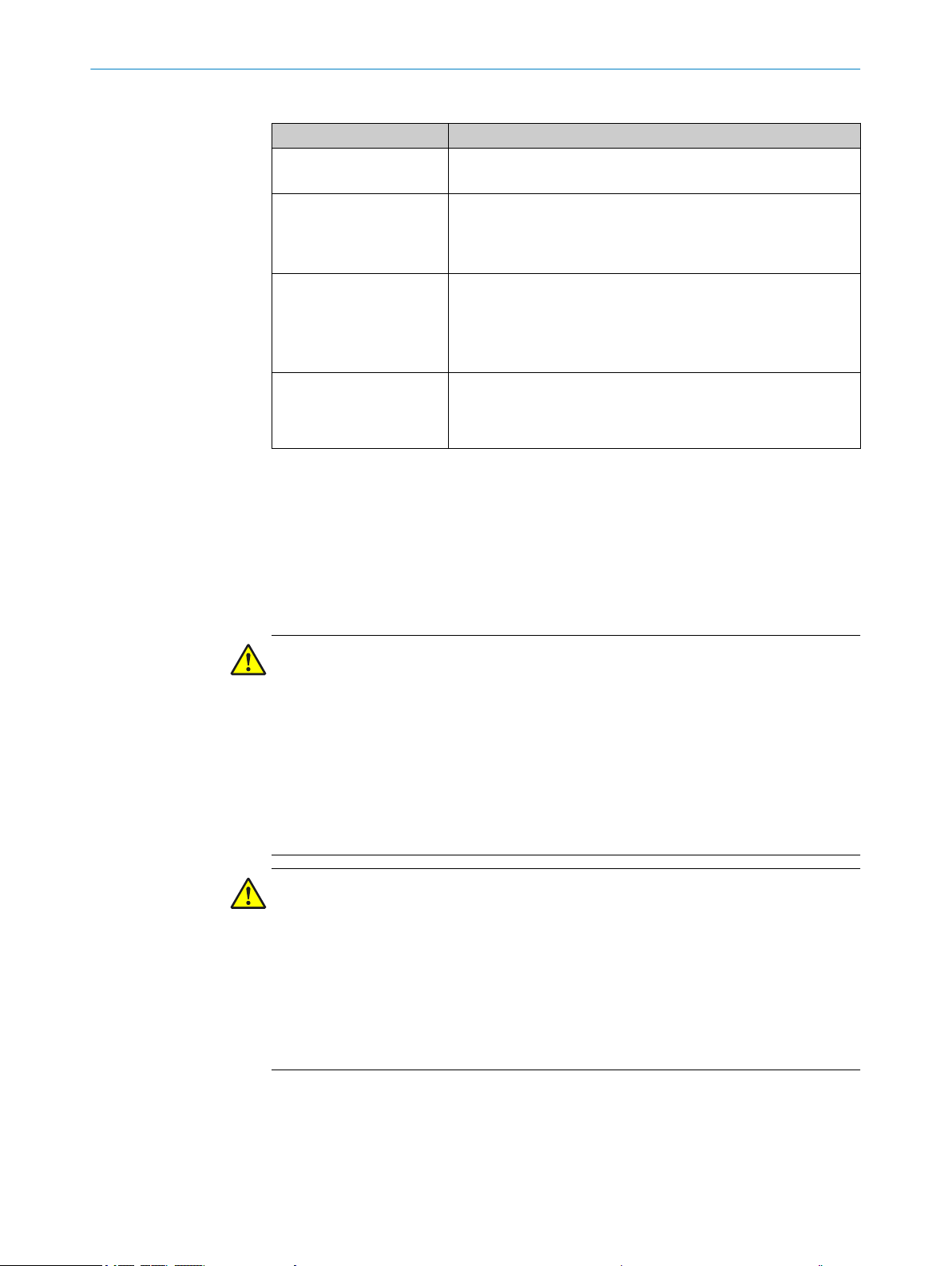
Table 1: Activities and technical requirements
Activities Qualification
Mounting, maintenance
Electrical installation,
device replacement
Basic practical technical training
■
Knowledge of the current safety regulations in the workplace
■
Practical electrical training
■
Knowledge of current electrical safety regulations
■
Knowledge of the operation and control of the devices in
■
their particular application
Commissioning, configura‐
tion
Basic knowledge of the WindowsTM operating system in use
■
Basic knowledge of the design and setup of the described
■
connections and interfaces
Basic knowledge of data transmission
■
Basic knowledge of bar code technology
■
Operation of the device for
the particular application
Knowledge of the operation and control of the devices in
■
their particular application
Knowledge of the software and hardware environment for
■
the particular application
2.7 Operational safety and particular hazards
SAFETY INFORMATION 2
Please observe the safety notes and the warnings listed here and in other chapters of
these operating instructions to reduce the possibility of risks to health and avoid dan‐
gerous situations.
The product is fitted with LEDs of the risk group 0. The accessible radiation from these
LEDs does not pose a danger to the eyes or skin.
WARNING
Electrical voltage!
Electrical voltage can cause severe injury or death.
■
Work on electrical systems must only be performed by qualified electricians.
■
The power supply must be disconnected when attaching and detaching electrical
connections.
■
The sensor must only be connected to a voltage source as set out in the require‐
ments in the operating instructions.
■
National and regional regulations must be complied with.
■
Safety requirements relating to work on electrical systems must be complied with.
WARNING
Dangerous equipotential bonding currents!
Improper grounding can lead to dangerous equipotential bonding currents, which may
in turn lead to dangerous voltages on metallic surfaces, such as the housing. Electrical
voltage can cause severe injury or death.
■
Work on electrical systems must only be performed by qualified electricians.
■
Follow the notes in the operating instructions.
■
Install the grounding for the product and the system in accordance with national
and regional regulations.
8021817/10Y9/2018-09-14 | SICK O PE R AT I NG IN S TR U CT I ON S | CLV60x
Subject to change without notice
9
Page 10
3 PRODUCT DESCRIPTION
3 Product description
3.1 Scope of delivery
The delivery of the device includes the following components:
Table 2: Scope of delivery
Item Component Comments
1 Device in the version ordered Depending on version
1 Printed safety notes -
3.2 Type code
The devices of the CLV60x product family are arranged according to the following type
code:
CLV xxx ‒ a b c d e
1 2 3 4 5 6 7
Table 3: Type code
Position Description Characteristic
1 Device name V-scanner code reader
2 Device type 601: Standard range
602: Long range
3.3 Type label
3 Version 0: Reading window at front
1: Reading window on side (angle 103°)
4 Connection type A: With open cable end
U: USB-A male connector
D: D-SUB male connector, 9-pin
5 Length of cable 1: Cable: approx. 1.5 m
2: Cable: approx. 2.0 m
6 Host interface 0: RS-232
1: USB
7 Supply voltage 0: DC 5 V ±10%
NOTE
Not all combinations are possible according to the type code. The available device vari‐
ants can be found online at:
www.sick.com/CLV60x
•
The type label gives information for identification of the device.
10
O PE R AT I NG IN S TR U CT I ON S | CLV60x 8021817/10Y9/2018-09-14 | SICK
Subject to change without notice
Page 11
D-79276 Reute
Made in Malaysia
CLV601-XXXXXXXX
P/N: 1XXXXXX
S/N: 1601 001
5V ± 10% 1,0 W Imax=0,3A
Manufactured: January 2017
25
6
5
4
3
2
1
7
Figure 1: Type label (example)
1
Ready
G Read
N Read
HW Err
UserDef1
Manufacturer’s address/country of production
1
Approval marks and test symbols
2
Production date
3
Technical data
4
Serial number
5
Material number
6
Type code
7
PRODUCT DESCRIPTION 3
3.4 Status indicators
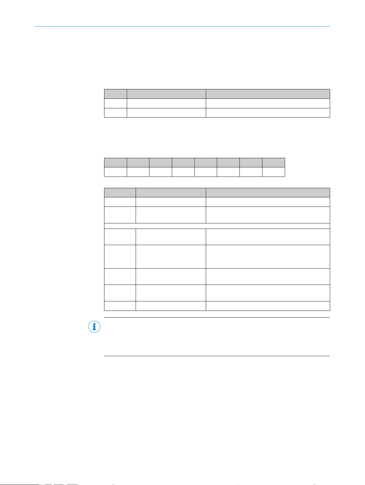
Figure 2: Status indicators
Status LED
1
Table 4: Display behavior of the LED
Color of LED Status Status
– OFF Device without supply voltage
Blue ON After switching on or after firmware download:
Green Lights up
briefly
Red Lights up
briefly
Red ON Hardware error (HW Err)
After switching on:
Parameter download for the device
Self-test successful, device ready for operation
Reading successful (Good Read)
Reading unsuccessful (No Read)
8021817/10Y9/2018-09-14 | SICK O PE R AT I NG IN S TR U CT I ON S | CLV60x
Subject to change without notice
11
Page 12
3 PRODUCT DESCRIPTION
Color of LED Status Status
Light blue – UserDef1 (reserved)
Red
Blue
Red ON Firmware download:
3.5 Product features and functions (overview)
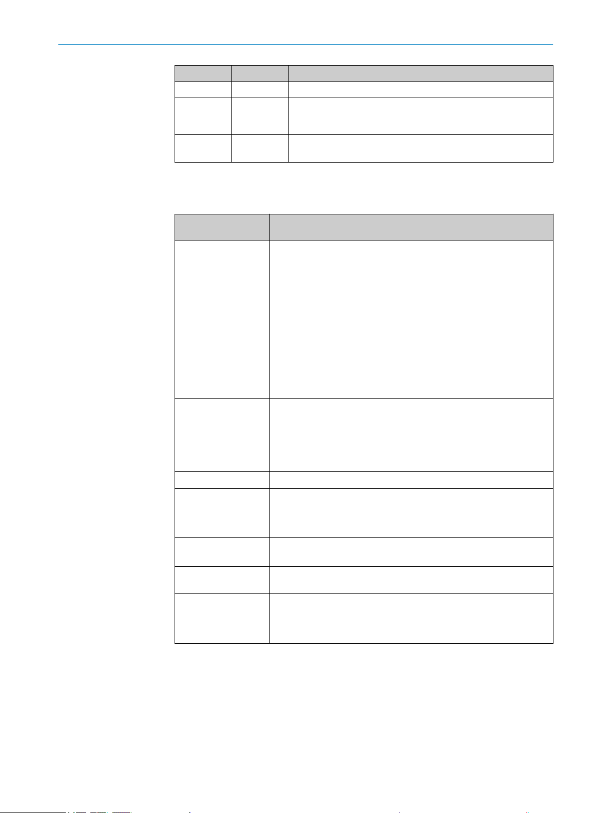
Table 5: Overview of product features and functions of the device
Product feature/func‐
tion
Security and ease of
use
Convenient operation/
configuration
Read operation modes
Read cycle
Bar code evaluation
Data processing
Data Communication
Flashes
alternately in
both colors
Characteristic
•
•
•
•
•
•
•
•
•
•
•
•
•
•
•
•
•
•
•
•
•
•
Firmware download
Error: Completion not successful
Rugged, compact metal housing
Automatic self-test at system start
Diagnostic tools for system setup and (remote) system monitoring
Configurable output of reading diagnostic data
Operating data polling, in case of error, issue of error code if
required
Test string function (heartbeat) can be activated to signal that the
device is ready for operation
Password-protected configuration mode via SOPAS ET
Future-oriented due to firmware update (FLASH PROM) via data
interface
Future-oriented SOPAS ET configuration software
Low power consumption
Configuration via SOPAS ET configuration software (online/
offline) or commands
LED status indicators
Profile programming with bar codes, generated and printed via
SOPAS ET
Beeper for actuating the device function can be switched off
Start/stop operation (one bar code bearing object per read cycle)
Pulse sources for start: Switching inputs, data interface (com‐
mand), auto pulse, free
Pulse sources for stop: Read cycle source, switching inputs, data
interface (command), timer, condition
All current 1D bar code types
No. of codes per reading interval: 1 ... 15 (auto-discriminating)
Influencing the output of the reading data by event-dependent
evaluation conditions
Host interface: A data output format can be configured for the
reading result, can be switched to various physical interfaces,
parallel operation possible
AUX interface: Fixed data output format
3.6 Operating principle
The CLV60x CMOS bar code reader detects bar codes in an illuminated scanning field
(scan line). The length of the scan line which can be used for evaluation (reading field
height) depends on the reading distance as a result of the V-shaped light emission.
The light pattern reflected from the bar code is recorded, processed, and decoded.
External sensors deliver information about the read cycle to control this process.
The read results are output to the device data interfaces and forwarded to a host/PC.
12
O PE R AT I NG IN S TR U CT I ON S | CLV60x 8021817/10Y9/2018-09-14 | SICK
Subject to change without notice
Page 13
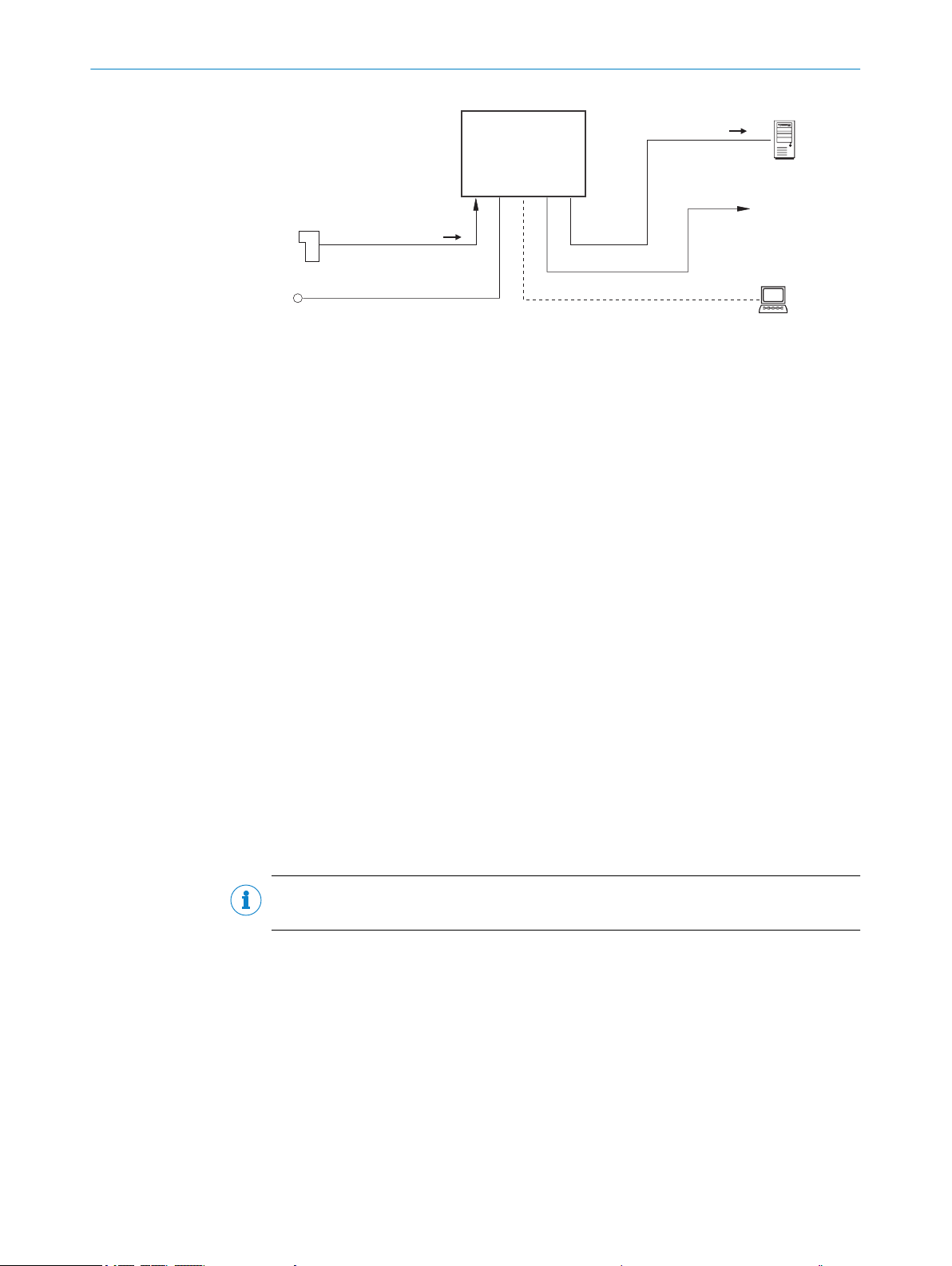
CLV60x
Reading pulse
Photoelectric switch
Power supply
Reading result
1
2
3
4
HOST
Data processing
5
Result function
e. g. Good Read /
No Read
6
Configuration
Diagnosis
SOPAS ETSOPAS ET
PC
7
Figure 3: Operating principle of the CLV60x
Voltage supply
1
Photoelectric sensor
2
Read cycle
3
Read result
4
Host/PC: Data processing
5
Read function, e.g. read successful / read unsuccessful
6
SOPAS ET PC software: Configuration, diagnosis
7
PRODUCT DESCRIPTION 3
Detailed wiring of the device and the connections to the host/PC and the external sen‐
sors are described in chapter Electrical installation.
3.6.1 Object trigger control
The device needs a suitable external signal (trigger source) for reporting an object in
the reading field in order to start an object-related read process. As standard, the start
signal is issued via an external read-cycle sensor (e.g. photoelectric sensor). As soon as
an object has passed the read-cycle sensor, a time window (“reading interval”) is
opened in the device for the read process.
Alternatively, a command triggers the read process via a data interface or the
SICK SENSOR network. In auto pulse mode, the device internally generates the reading
interval itself with an adjustable clock ratio.
The read cycle can be ended in several ways. For example, external triggering by the
read cycle source or a command, or internally by a timer or a evaluation condition to be
fulfilled.
NOTE
The SOPAS ET configuration software can be used to configure the trigger source.
3.7 Reading operation mode
In “start/stop” operation, there is only ever one object in the reading field during the
reading process, i.e., all read codes can be clearly assigned to the object. As standard,
starting and stopping of the reading process are controlled by one or two read cycle
sensor(s) at the start and end of the reading field.
In this case, the distance between the read cycle sensors determines the size of the
reading field. The reading process can alternatively be controlled with command strings
via the data interface.
8021817/10Y9/2018-09-14 | SICK O PE R AT I NG IN S TR U CT I ON S | CLV60x
Subject to change without notice
13
Page 14

Data
output 5
Trigger 2:
Stop
reading 2
Trigger 1:
Start
reading 3
Reading field 4
Start/Stop mode 1
3 PRODUCT DESCRIPTION
The output of the read results is either carried out at the end of the read cycle (the rear
edge of the object has left the end of the reading field) or even during the read cycle if
certain configurable conditions are met.
Figure 4: Start/stop operating mode of the device in stand-alone operation
1
2
3
4
5
Start/stop operation
Trigger 2: Stop reading
Trigger 1: Start reading
Reading field
Data output
NOTE
The SOPAS ET configuration software can be used to configure the reading operation
mode.
O PE R AT I NG IN S TR U CT I ON S | CLV60x 8021817/10Y9/2018-09-14 | SICK
14
Subject to change without notice
Page 15

4 Transport and storage
4.1 Transport
For your own safety, please read and observe the following notes:
NOTICE
Damage to the product due to improper transport.
■
The device must be packaged for transport with protection against shock and
damp.
■
Recommendation: Use the original packaging as it provides the best protection.
■
Transport should be performed by trained specialist staff only.
■
The utmost care and attention is required at all times during unloading and trans‐
portation on company premises.
■
Note the symbols on the packaging.
■
Do not remove packaging until immediately before you start mounting.
TRANSPORT AND STORAGE 4
4.2
Unpacking
■
Before unpacking, it may be necessary to equalize the temperature to protect the
device from condensation.
■
Handle the device with care and protect it from mechanical damage.
4.3 Transport inspection
Immediately upon receipt in Goods-in, check the delivery for completeness and for any
damage that may have occurred in transit. In the case of transit damage that is visible
externally, proceed as follows:
■
Do not accept the delivery or only do so conditionally.
■
Note the scope of damage on the transport documents or on the transport com‐
pany's delivery note.
■
File a complaint.
NOTE
Complaints regarding defects should be filed as soon as these are detected. Damage
claims are only valid before the applicable complaint deadlines.
4.4 Storage
Store the device under the following conditions:
■
Recommendation: Use the original packaging.
■
Electrical connections are provided with protective caps and plugs (as they are on
delivery).
■
Do not store outdoors.
■
Store in a dry area that is protected from dust.
■
So that any residual damp can evaporate, do not package in airtight containers.
■
Do not expose to any aggressive substances.
■
Protect from sunlight.
■
Avoid mechanical shocks.
■
Storage temperature: see "Technical data", page 35.
■
Relative humidity: see "Technical data", page 35.
■
For storage periods of longer than 3 months, check the general condition of all
components and packaging on a regular basis.
8021817/10Y9/2018-09-14 | SICK O PE R AT I NG IN S TR U CT I ON S | CLV60x
Subject to change without notice
15
Page 16

5 MOUNTING
5 Mounting
5.1 Overview of mounting procedure
Selecting and preparing the mounting location.
•
Mounting the device.
•
Align device towards object with bar code.
•
Connect device to data cable and supply cable.
•
Adjust the device.
•
WARNING
Risk of injury due to damage to the device
For reasons of safety, a device which is visibly damaged must not be operated or must
be immediately taken out of operation. Damage includes, for example:
Housing: Cracked or broken
•
Reading window lens: Cracked or broken
•
Device with connector: Over-rotation of the connector, cracks, or being torn from
•
the housing
Device with fixed cable: Damage to the cable outlet or cable itself
•
5.2 Mounting instructions
■
Observe the technical data of the device when selecting an installation location.
■
For typical space requirements for the device, see type-specific dimensional draw‐
ing and reading field diagram.
■
To prevent condensation, avoid exposing the device to rapid changes in tempera‐
ture.
■
Protect the device from direct sunlight.
■
The device must only be mounted using the pairs of blind tapped holes provided
for this purpose.
■
Shock and vibration-free mounting.
Equipment required
NOTE
The screws are for mounting the device on mounting equipment (bracket) supplied
by the user. Screw length is dependent on the mounting base (wall thickness of
the bracket).
■
Tool and tape measure
5.3
Mounting location
When selecting the mounting location, the following factors are significant:
Basic allocation of the scan line to the bar code
b
Reading distance to the bar code and aperture angle α
b
Angle alignment of the device
b
Avoidance of surface reflections
b
Count direction of the reading angle (position of the bar code along the scan line)
b
5.3.1 Basic alignment of the scan line to the bar code
Please note that the complete red illumination line does not correspond to the reading
field of the device. About 7.5%, seen from both ends, cannot be read.
16
O PE R AT I NG IN S TR U CT I ON S | CLV60x 8021817/10Y9/2018-09-14 | SICK
Subject to change without notice
Page 17

5.3.2 Reading distance to the bar code and aperture angle α
β
α
γ
1
2
The maximum distance from the reading window of the device to the bar code may not
exceed the design values for the device. Because of the V-shaped deflection of the
beams, the usable length of the scan line for evaluation (reading field height) depends
on the reading distance.
In the specification diagrams, the height of the reading field dependent on the reading
distance is shown for differing resolutions (module widths), "Technical data", page 35.
5.3.3 Angle alignment of the device
The optimum alignment of the device is achieved when the scan line crosses the
stripes of the bar code as close to a right angle as possible (tilt and inclination). Possi‐
ble reading angles that can arise between scan line and bar code at all three levels in
the area must be taken into account.
MOUNTING 5
Figure 5: Line scanner: Read angle occurring between scanning line and bar code
Depth of field
1
Reading distance
2
NOTE
The specified maximum values can only be achieved if conditions are optimal. The
actual maximum depends on the module width, code type, print contrast, ambient light,
distance and scanning frequency.
Table 6: Permitted read angle between scanning line and bar code
Angle Limit value
Tilt α ±5° (with code resolution ≥ 0.125 mm)
Pitch β ±6° (with code resolution ≥ 0.2 mm)
Skew γ ±20° (with code resolution ≥ 0.2 mm)
5.3.4 Avoidance of surface reflections
If the light of the scan line(s) hits the surface of the bar code precisely vertically, this
may cause interference when the light reflected back is received. To prevent this effect,
the device must be mounted so that the light emitted is tilted relative to the vertical.
±10° (with code resolution ≥ 0.15 mm)
±15° (with code resolution ≥ 0.2 mm)
±25° (with code resolution ≥ 0.35 mm)
±15° (with code resolution ≥ 0.5 mm)
±30° (with code resolution ≥ 0.5 mm)
8021817/10Y9/2018-09-14 | SICK O PE R AT I NG IN S TR U CT I ON S | CLV60x
Subject to change without notice
17
Page 18

103° 103°
1 2
2 31
5 MOUNTING
NOTE
Optimal results are achieved when the scan line is tilted about 13° relative to the verti‐
cal. The version with a side reading window therefore features a light emission angle of
103°.
Figure 6: Avoiding surface reflections: Angle between light emitted and bar code (tilting away
from vertical)
Product variant with reading window at the front (top view)
1
Product variant with reading window at the side (top view)
2
5.3.5 Counting direction of the reading angle and the code angle
The device can scan and decode several bar codes at each reading.
At the same time, the location-specific reading diagnostics data are determined for
each of them:
■
The reading angle, starting from the reading window, at which the device detects
the bar code center on the red scanning line of the deflected scanning beam can
be output as an RA (reading angle) value.
By determining the RA value, identical bar codes (code type, code length, and data con‐
tent) can be separated, and the bar code data assigned based on their position on the
object. 1 RA corresponds to about 0.71° (50 RAs correspond to 35.4°, 100 RAs corre‐
spond to an aperture angle of 70.8°).
Figure 7: Counting direction and RA value calculation
Counting direction (aperture angle in reading direction)
1
Product variant with reading window at the front
2
Product variant with reading window at the side
3
5.4 Mounting the device
18
O PE R AT I NG IN S TR U CT I ON S | CLV60x 8021817/10Y9/2018-09-14 | SICK
Subject to change without notice
Page 19

MOUNTING 5
NOTICE
Risk of damaging the device!
Observe the maximum screw-in depth of the blind hole thread. Longer screws than
specified damage the device.
Use screws of suitable length.
b
1. Prepare the base for mounting the device bracket.
2. Place the object with the bar code in the view of the device in the position where
the reading is to take place (conveyor static).
3. Align device with the bar code by sight. When doing so, be aware of the following:
– Make sure that the device side with the reading window is aligned as near as
possible to parallel to the bar code surface.
– During reading, note the reading angle that occurs see "Angle alignment of
the device", page 17.
– If the position of the bar code within the scanning line is relevant for the eval‐
uation, bear in mind the count direction of the code position see "Counting
direction of the reading angle and the code angle", page 18.
4. Mount the device bracket onto the base.
5. Tighten screws through the bracket into the blind tapped holes of the device and
slightly tighten.
8021817/10Y9/2018-09-14 | SICK O PE R AT I NG IN S TR U CT I ON S | CLV60x
Subject to change without notice
19
Page 20

6 ELECTRICAL INSTALLATION
6 Electrical installation
6.1 Safety
6.1.1 Notes on the electrical installation
■
The electrical installation must only be performed by electrically qualified person‐
nel.
■
Standard safety requirements must be met when working on electrical systems.
■
Only switch on the supply voltage for the device when the connection tasks have
been completed and the wiring has been thoroughly checked.
■
When using extension cables with open ends, ensure that bare wire ends do not
come into contact with each other (risk of short-circuit when supply voltage is
switched on!). Wires must be appropriately insulated from each other.
■
Wire cross-sections in the supply cable from the customer's power system must be
selected in accordance with the applicable standards. When this is being done in
Germany, observe the following standards: DIN VDE 0100 (Part 430) and DIN VDE
0298 (Part 4) and/or DIN VDE 0891 (Part 1).
■
Electrical circuits connected to the device must be configured as SELV circuits
(SELV = safety extra-low voltage) in accordance with IEC 60950-1 or ES1 in accor‐
dance with IEC 62368-1.
6.2
NOTE
Layout of data cables
■
Use screened data cables with twisted-pair wires.
■
Implement the screening design correctly and completely.
■
To avoid interference, e.g. from switching power supplies, motors, clocked drives,
and contactors, always use cables and layouts that are suitable for EMC.
■
Do not lay cables over long distances in parallel with power supply cables and
motor cables in cable channels.
Prerequisites for safe operation of the device
WARNING
Risk of injury and damage caused by electrical current!
As a result of equipotential bonding currents between the device and other grounded
devices in the system, faulty grounding of the device can give rise to the following dan‐
gers and faults:
■
Metal housings are vulnerable to dangerous currents.
■
Devices will behave incorrectly or be destroyed.
■
Cable shielding will be damaged by overheating and cause cable fires.
Remedial measures
■
Only skilled electricians should be permitted to carry out work on the electrical sys‐
tem.
■
If the cable insulation is damaged, disconnect the voltage supply immediately and
have the damage repaired.
■
Ensure that the ground potential is the same at all grounding points.
■
Where local conditions do not meet the requirements for a safe earthing method,
take appropriate measures (e.g., ensuring low-impedance and current-carrying
equipotential bonding).
20
O PE R AT I NG IN S TR U CT I ON S | CLV60x 8021817/10Y9/2018-09-14 | SICK
Subject to change without notice
Page 21

SICK
Device
7 46
Power Supply
U
= 8
= 9
1 2 3
I
5
System
Controller
ELECTRICAL INSTALLATION
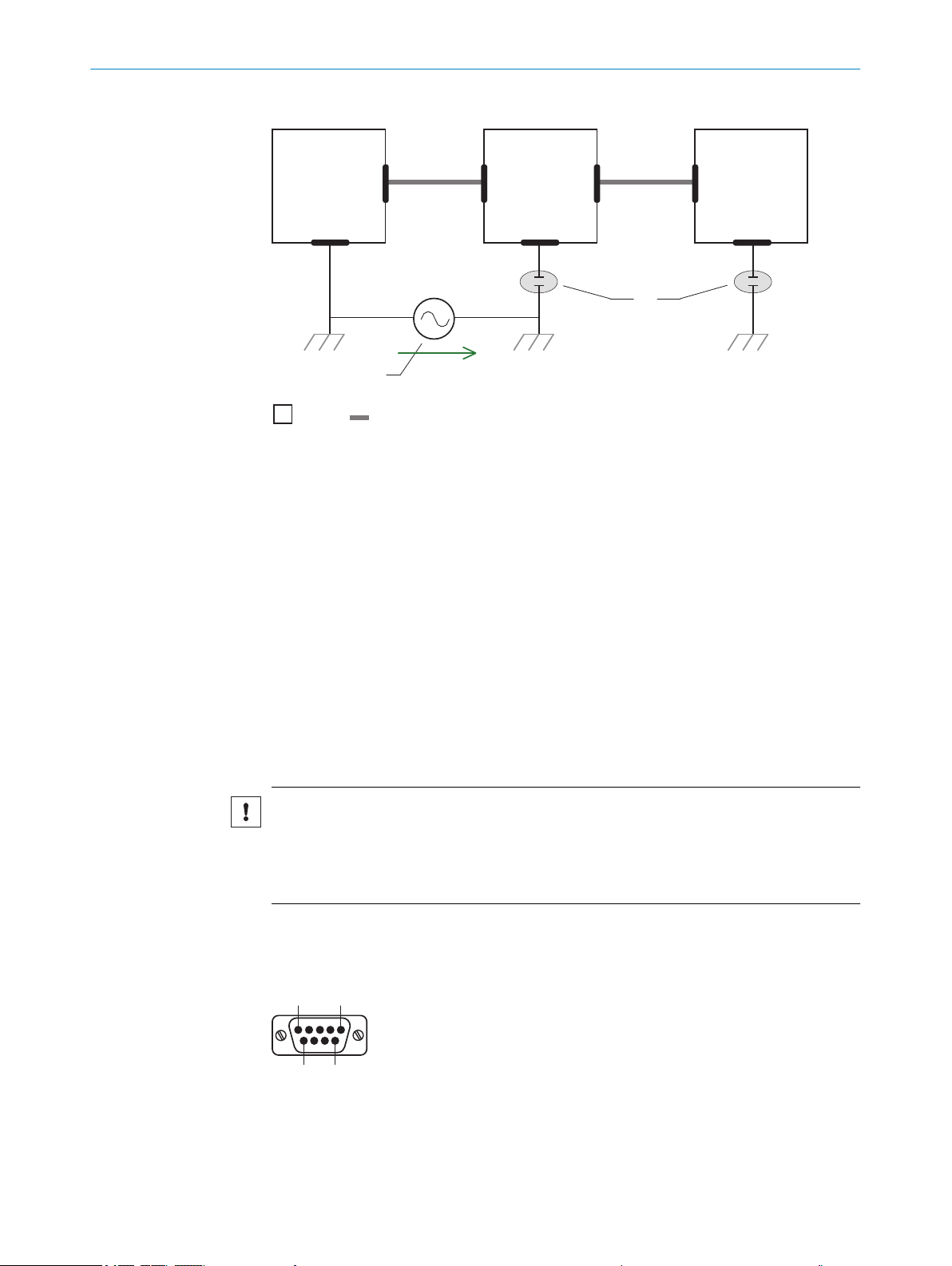
The device is connected to the peripheral devices (voltage supply, any local pulse sen‐
sor(s), system controller) via shielded cables. The cable shield – for the data cable,
for example – rests against the metal housing of the device. The device can be
grounded through the cable shield or through a blind tapped hole in the housing,
for example.
If the peripheral devices have metal housings and if the cable shields also lie on their
housings, it is assumed that all devices involved in the installation have the same
ground potential.
This is achieved by complying with the following conditions:
■
Mounting the devices on conductive metal surfaces
■
Correctly grounding the devices and metal surfaces in the system
■
If necessary: low-impedance and current-carrying equipotential bonding between
areas with different ground potentials
6
Figure 8: Example: Occurrence of equipotential bonding currents in the system configuration
System controller
1
Device
2
Voltage supply
3
Grounding point 2
4
Closed current loop with equalizing currents via cable shield
5
Ground potential difference
6
Grounding point 1
7
Metal housing
8
Shielded electrical cable
9
If these conditions are not fulfilled, equipotential bonding currents can flow along the
cable shielding between the devices due to differing ground potentials and cause the
hazards specified. This is, for example, possible in cases where there are devices within
a widely distributed system covering several buildings.
Remedial measures
The most common solution to prevent equipotential bonding currents on cable shields
is to ensure low-impedance and current-carrying equipotential bonding. If this is not
possible, the following solution approaches serve as a suggestion.
NOTICE
We expressly advise against opening up the cable shields. This would mean that the
EMC limit values can no longer be complied with and that the safe operation of the
device data interfaces can no longer be guaranteed.
8021817/10Y9/2018-09-14 | SICK O PE R AT I NG IN S TR U CT I ON S | CLV60x
Subject to change without notice
Measures for widely distributed system installations
21
Page 22

Electro-
optical
signal
isolator
Electro-
optical
signal
isolator
Power
Supply
SICK
Device
1 2 2 43
6 5
System
Controller
= 7
= 8
= 9
ELECTRICAL INSTALLATION
6
On widely distributed system installations with correspondingly large potential differ‐
ences, the setting up of local islands and connecting them using commercially available
electro-optical signal isolators is recommended. This measure achieves a high degree
of resistance to electromagnetic interference.
Figure 9: Example: Prevention of equipotential bonding currents in the system configuration by
the use of electro-optical signal isolators
System controller
1
Electro-optical signal isolator
2
Device
3
Voltage supply
4
Grounding point 2
5
Grounding point 1
6
Metal housing
7
Shielded electrical cable
8
Optical fiber
9
The use of electro-optical signal isolators between the islands isolates the ground loop.
Within the islands, a stable equipotential bonding prevents equalizing currents on the
cable shields.
Measures for small system installations
For smaller installations with only slight potential differences, insulated mounting of the
device and of peripheral devices may be a sufficient solution.
22
O PE R AT I NG IN S TR U CT I ON S | CLV60x 8021817/10Y9/2018-09-14 | SICK
Subject to change without notice
Page 23
U
System
Controller
Power Supply
SICK
Device
8 6
5
21 3
4
7
= 9
= ß
51
96
ELECTRICAL INSTALLATION 6
Figure 10: Example: Prevention of equipotential bonding currents in the system configuration by
the insulated mounting of the device
System controller
1
Device
2
Voltage supply
3
Grounding point 3
4
Insulated mounting
5
Grounding point 2
6
Grounding potential difference
7
Grounding point 1
8
Metal housing
9
Shielded electrical cable
ß
6.3 Interface description
8021817/10Y9/2018-09-14 | SICK O PE R AT I NG IN S TR U CT I ON S | CLV60x
Subject to change without notice
Even in the event of large differences in the ground potential, ground loops are effec‐
tively prevented. As a result, equalizing currents can no longer flow via the cable shields
and metal housing.
NOTICE
The voltage supply for the device and the connected peripheral devices must also guar‐
antee the required level of insulation.
Under certain circumstances, a tangible potential can develop between the insulated
metal housings and the local ground potential.
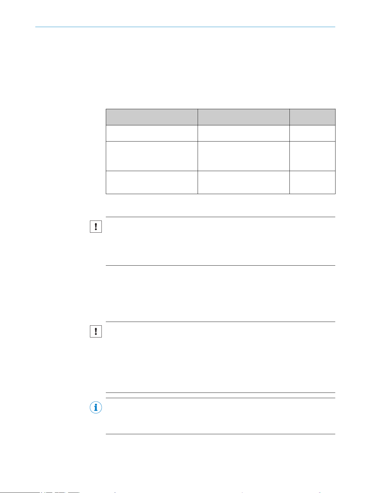
Connection of devices with cable and RS-232 male connector
Figure 11: Male connector, D-Sub, 9-pin
23
Page 24

6 ELECTRICAL INSTALLATION
Table 7: Pin assignment on 9-pin D-Sub-HD male cable connector
Pin Signal Function
1 In1 Digital switching input
2 RxD (HOST) HOST interface (receiver)
3 TxD (HOST) HOST interface (sender)
4 Out1 Digital switching output 1
5 GND Ground
6 Out2 Digital switching output 2
7 RxD (AUX) AUX interface (receiver)
8 TxD (AUX) AUX interface (sender)
9 +5V Supply voltage
Connection of devices with cable and USB male connector
Devices with cable and USB-a_connector can be operated in the Keyboard wedge (HID),
Virtual COM port (CDC) and SOPAS (vendor-specific) operating modes. Switching over is
not necessary since this happens automatically via USB Composite.
Properties of different operating modes:
USB-HID (Human Interface Device): Keyboard connector, scanner is operated as a
•
generic USB keyboard.
Virtual COM Port: Scanner is operated via an emulator as a serial RS-232 device.
•
SOPAS-USB: Alternative to the virtual COM port
•
Table 8: Pin assignment on 4-pin USB A male cable connector
Pin Signal Function
1 +5V Supply voltage
2 Data- Data input
3 Data+ Data output
4 GND Ground
Before connecting for the first time, install the USB COM port driver (available at
www.sick.com/CLV60x). A standard virtual COM port driver is integrated from Windows
10. The SOPAS ET software must be installed on the host computer to use SOPAS USB.
6.4 Wiring interfaces
6.4.1 Connecting the supply voltage
The device must be connected to a power supply unit with the following properties:
Supply voltage 5 V DC ± 10% (stabilized safety extra-low voltage SELV (EN
•
60950-1) and LPS (IEC 60950-1) or ES-1 and PS2 (EN 62368-1) as per currently
valid standards)
Voltage source with at least 1.5 W power
•
When configuring the voltage supply, the switch-on current of the device must be taken
into consideration. The initial power consumption depends on the input capacitors of
the device. The input capacitor is about 50 μF for the RS232 variant. If, for example, 10
devices with a voltage supply are used, that means:
Pmax = 10 * 1.5 W = 15 W
Sum of capacitators = 10 * 50 μF = 500 μF
The voltage supply should be able to process 500 μF load for commissioning.
24
O PE R AT I NG IN S TR U CT I ON S | CLV60x 8021817/10Y9/2018-09-14 | SICK
Subject to change without notice
Page 25

6.4.2 Wiring the data interface
RS-232
!
"
§
Device 1 Host
TxD
RxD
GND
RxD
TxD
GND
Wiring the serial data interface
The maximum data transmission rate for the serial interface depends on the length of
cable and on the type of interface. The following recommendations apply:
Table 9: Data transmission rates
Interface type Data transmission rate Distance to the target computer
RS-232 Up to 19.2 kBd
NOTICE
Risk of damage to the internal interface modules!
If the serial data interfaces are wired incorrectly, then electronic components in the
device could get damaged.
■
Observe the information on wiring.
■
Carefully check the wiring prior to switching on the device.
38.4 kBd ... 57.6 kBd
115.2 kBd … 500 kBd
ELECTRICAL INSTALLATION 6
(host)
Max. 10 m
Max. 3 m
Max. 2 m
Figure 12: Internal circuitry for RS-232 data interface
Device
1
Pin assignment: See RS-232 pin assignment for the respective device
!...§
6.4.3 Wiring digital switching inputs
Physical switching inputs on the device
The physical switching inputs can be used to start and/or end the read cycle.
The number of switching inputs available at the connections will vary depending on the
device, see "Interface description", page 23.
Table 10: Characteristic data for the switching inputs
Switching behavior Power at the input starts the internal reading interval of the device
Properties Opto-decoupled
Electrical values The electrical values are identical for all switching inputs.
[default: active high, debounce: min. 1 ms, max. 10000 ms, stan‐
dard 10 ms]
Reverse polarity protected
Digital low: Vin < 0.8 V
Digital high: Vin > 3 V
8021817/10Y9/2018-09-14 | SICK O PE R AT I NG IN S TR U CT I ON S | CLV60x
Subject to change without notice
25
Page 26

6 ELECTRICAL INSTALLATION
Figure 13: Wiring of a digital input with external NPN sensor
6.4.4 Wiring digital switching outputs
Physical switching outputs on the device
The physical switching outputs can be allocated independently of each other with vari‐
ous functions for event status indication. If the allocated event occurs in the read
process, then the corresponding switching output is live after the end of the clock read‐
ing pulse for the selected pulse duration.
Table 11: Characteristic data for the switching outputs
Switching behavior NPN switching to supply voltage V
Properties Short-circuit protected
Electrical values The electrical values are identical for all switching outputs.
S
Temperature protected
Not electrically isolated from V
5 V ≤ V
I
out
≤ 30 V
out
≤ 50 mA
S
Voltage peak at maximum switching current ≤ 0.8 V
(US −1.5 V) ≤ Ua ≤ Us at Ia ≤ 50 mA
26
Figure 14: Wiring a switching output
Max. load 50 mA
1
DC 5 ... 30 V
2
Extension: Additional logical switching outputs in the device in the case of physical
“external” switching outputs on the optional connection module
NOTE
Capacitive loads on the switching outputs have an effect on the switch-on and switchoff behavior. The maximum capacity of 100 mF and an external load resistance of max‐
imum 10 kΩ is a limit value.
O PE R AT I NG IN S TR U CT I ON S | CLV60x 8021817/10Y9/2018-09-14 | SICK
Subject to change without notice
Page 27

ELECTRICAL INSTALLATION 6
1. Connect the switching outputs according to the application.
2. For the thorough check of the switching functions, use a high resistance digital
voltmeter and wire the switching outputs with a load.
This prevents the display of incorrect voltage values/output states.
8021817/10Y9/2018-09-14 | SICK O PE R AT I NG IN S TR U CT I ON S | CLV60x
Subject to change without notice
27
Page 28

ROM
PROM
RAM
RAM
Database
(Hard drive)
Bar code scanner
PC with SOPAS-ET
configuration software
Parameter set in the
working memory of the
bar code scanner
Permanently saved
parameter set
Saved project file (*.sopas)
with archived parameter set
Factory default of the
bar code scanner
Opened project file with
current parameter set
7 COMMISSIONING
7 Commissioning
7.1 Overview of the commissioning steps
Commissioning of the device with factory default
•
Installing the SOPAS ET configuration software
•
Connection of the device to PC/notebook with the SOPAS ET configuration soft‐
•
ware
Adjustment and configuration of the device to optimize functionality
•
Test of the device for correct functionality in read operation
•
7.2 SOPAS ET configuration software
The SOPAS-ET configuration software can be used to adapt the device to the reading
situation on site. The configuration data is stored and archived as a parameter set
(project file) on the PC.
7.3 Initial Commissioning
The device is adjusted to the reading situation on site using the SOPAS ET configuration
software. The starting point for this is the default factory settings, which can be
adjusted to optimize the device. In order to do this, the SOPAS ET configuration soft‐
ware is used to create an application-specific parameter set, which can be loaded per‐
manently into the device and saved and archived as a project file (SOPAS file with con‐
figuration data) on the PC.
7.4
28
Figure 15: Saving the parameter set and configuration with SOPAS ET
Fine adjustment and further configuration
NOTE
The additional settings and the fine adjustment depend on the respective application
situation.
User level, parameter download for device
The user is automatically logged into the device in the “Authorized customer” level and
can change parameters which are immediately transmitted to the device (default set‐
ting).
O PE R AT I NG IN S TR U CT I ON S | CLV60x 8021817/10Y9/2018-09-14 | SICK
Subject to change without notice
Page 29

COMMISSIONING 7
Configuration via Quickstart
The Quickstart tab offers an overview of the most important parameters and enables
quick evaluation of code content. Among others, functions such as “Evaluation win‐
dow,” “Percentage evaluation,” “Code configuration,” and “Adjusting mode” are avail‐
able via the Quickstart.
Evaluation window
The evaluation window shows the code content, the object index, the code type, the
code security, and the device number of the reading device.
Percentage evaluation
Percentage evaluation permanently assesses the quality of the reading. Bar codes are
not assessed. Here, the bar codes must not be subjected to any conveying movement.
The device performs 100 scans in each case and evaluates the reading quality. The
device continuously emits read results every 2 s via the AUX interface, together with the
read diagnostic data. A timer starts when percentage evaluation is called. If a manual
abort is not carried out, the device automatically returns to read mode after 5 min.
Code configuration
In the factory default setting, the device decodes the following code types:
Code 39
•
2/5 Interleaved
•
Code 128 family
•
Scanning frequency
The scanning frequency is 750 HZ, is cannot be adjusted.
Object trigger control
If the device is to be operated with an additional read cycle sensor, for example, a pho‐
toelectric sensor on the “Sensor 1” switching input, select the “Sensor 1” setting
(Device tree > Parameters > Reading configuration > Object trigger control).
Test and, if necessary, modify the specified settings when operating the system under
real conditions.
8021817/10Y9/2018-09-14 | SICK O PE R AT I NG IN S TR U CT I ON S | CLV60x
Subject to change without notice
29
Page 30

8 OPERATION
8 Operation
8.1 Operating options
The device can be configured according to application in the following manner:
■
Locally at the device with the SOPAS ET configuration software. Protection of the
parameter set as a configuration file on the PC in SOPAS ET. Access to the device
via AUX interface.
■
As an alternative to the SOPAS ET configuration software, command strings are
available, upon which the operator interface of the configuration software is also
based. These are also for the triggering of device functions (e.g. reading). Docu‐
ments on the command strings can be obtained from SICK on request.
■
Profile programming by reading a set of printed configuration bar codes. Can be
created via SOPAS ET.
The SOPAS ET configuration software is used for device diagnostics in case of a fault.
In normal operation, the device operates fully automatically.
30
O PE R AT I NG IN S TR U CT I ON S | CLV60x 8021817/10Y9/2018-09-14 | SICK
Subject to change without notice
Page 31
9 Maintenance
9.1 Maintenance
During operation, the device works maintenance-free.
Depending on the assignment location, the following preventive maintenance tasks
may be required for the device at regular intervals:
Table 12: Maintenance schedule
Maintenance work Interval To be carried out
Clean housing and front screen Cleaning interval depends on ambi‐
Check screw connections and plug
connectors
Check that the unused connections
are sealed with protective caps or
plugs
MAINTENANCE 9
ent conditions and climate.
Interval depends on the place of use,
ambient conditions, or operational
regulations. Recommended: At least
every 6 months.
Interval depends on ambient condi‐
tions and climate. Recommended: At
least every 6 months.
by
Specialist
Specialist
Specialist
9.2 Cleaning
NOTICE
Equipment damage due to improper cleaning.
Improper cleaning may result in equipment damage.
■
Only use recommended cleaning agents.
■
Never use sharp objects for cleaning.
Cleaning the reading window
At regular intervals, check the reading window and the housing of the device for accu‐
mulated dirt. This is especially relevant in harsh operating environments (dust, abra‐
sion, damp, fingerprints, etc.).
The reading window lens must be kept clean and dry during operation.
NOTICE
Damage to the reading window.
Reduced analysis performance due to scratches or streaks on the window.
■
Clean the window only when wet.
■
Use a mild cleaning agent that does not contain powder additives. Do not use
aggressive cleaning agents, such as acetone, etc.
■
Avoid any movements that could cause scratches or abrasions on the window.
■
Only use cleaning agents suitable for the screen material.
NOTE
Static charge causes dust particles to adhere to the reading window. This effect can be
avoided by using an anti-static cleaning agent in combination with the SICK lens cloth
(can be obtained from www.sick.com).
8021817/10Y9/2018-09-14 | SICK O PE R AT I NG IN S TR U CT I ON S | CLV60x
Subject to change without notice
31
Page 32

9 MAINTENANCE
Cleaning procedure:
Clean the reading window only with a clean, damp, lint-free cloth, and a mild anti-
b
static lens cleaning fluid.
NOTICE
If the inspection window is scratched or damaged (cracked or broken), the lens must be
replaced. Contact SICK Support to arrange this.
■
If the inspection window is cracked or broken, take the device out of operation
immediately for safety reasons and have it repaired by SICK.
Cleaning the housing
In order to ensure that heat is adequately dissipated from the device, the housing sur‐
face must be kept clean.
Clear the build up of dust on the housing with a soft brush.
b
Cleaning other optical surfaces
Depending on how the reading station is equipped, additional local sensors may have
other surfaces with an optical effect installed (e.g., photoelectric sensor for an external
reading pulse). Contamination on these sensors can result in faulty switching behavior.
To avoid faulty switching behavior, remove dirt from the optical surfaces of the
b
external sensors.
Figure 16: Cleaning the external optical sensors (read pulse encoder)
32
O PE R AT I NG IN S TR U CT I ON S | CLV60x 8021817/10Y9/2018-09-14 | SICK
Subject to change without notice
Page 33

10 Troubleshooting
10.1 Overview of possible errors and faults
Table 13: Errors and faults
Situation Error/fault
Mounting
Electrical installation
Configuration
Operation
■
■
■
■
■
■
■
■
■
TROUBLESHOOTING 10
Device poorly aligned to the object with the bar code (e.g.
dazzle).
Read-cycle sensor incorrectly positioned (e.g., internal read‐
ing gate is opened too early or closed too late).
Incremental encoder incorrectly positioned.
Data interfaces of the device incorrectly wired.
Functions not adapted to local conditions, e.g. parameters
for the data interface not set correctly.
Device limits not observed, e.g. reading distance, aperture
angle.
Read cycle trigger source not selected correctly.
Read cycle control incorrect and/or not suitable for the
object.
Device faults (hardware/software).
10.2 Detailed fault analysis
10.2.1 LEDs on the device
The conditions that can be read from the device LEDs on the sensor housing (see "Sta‐
tus indicators", page 11) include:
■
Operational readiness (Ready)
■
Reading result status (Good Read or No Read)
■
Hardware fault
■
Firmware download status
■
Connection status of the device
The LED display can indicate possible errors or faults. Further information on this can
be found in the “System Information” section.
10.2.2 System information
The device outputs faults in different ways. Fault output is staggered and thus allows
for an increasingly detailed level of analysis.
Communication errors can occur when transmitting data to the device. The device
•
then returns a fault code.
For faults that occur during reading, the device writes fault codes in the status log
•
(see "Status log", page 33).see "Status log", page 33.
10.3 Status log
NOTE
The status log is retained even after switching the device off and on again.
The device distinguishes between four types of fault:
■
Information
■
Warning
8021817/10Y9/2018-09-14 | SICK O PE R AT I NG IN S TR U CT I ON S | CLV60x
Subject to change without notice
33
Page 34

10 TROUBLESHOOTING
■
Error
■
Critical fault
The device saves only the last five entries for each fault type.
10.3.1 Displaying the status log
To display the status log, the SOPAS ET configuration software must be connected with
the device online.
1. Connect the SOPAS ET configuration software to the device.
2. Open CLV6xx in the project tree: Service > System Status > System Information
tab.
10.4 Repairs
Repair work on the device may only be performed by qualified and authorized person‐
nel from SICK AG. Interruptions or modifications to the device by the customer will inval‐
idate any warranty claims against SICK AG.
10.5 Returns
Do not dispatch devices to the SICK Service department without consultation.
b
The device must be sent in the original packaging or an equivalent padded pack‐
b
aging.
10.6 Disposal
NOTE
To enable efficient processing and allow us to determine the cause quickly, please
include the following when making a return:
■
Details of the contact person
■
Description of the application
■
Description of the fault that occurred
Any device which can no longer be used must be disposed of in an environmentally
friendly manner in accordance with the applicable country-specific waste disposal regu‐
lations. Do not dispose of the product along with household waste.
NOTICE
Danger to the environment due to improper disposal of the device.
Disposing of devices improperly may cause damage to the environment.
Therefore, observe the following information:
■
Always observe the valid regulations on environmental protection.
■
Separate the recyclable materials by type and place them in recycling containers.
34
O PE R AT I NG IN S TR U CT I ON S | CLV60x 8021817/10Y9/2018-09-14 | SICK
Subject to change without notice
Page 35

11 Technical data
NOTE
The relevant online data sheet for your product, including technical data, dimensional
drawing, and connection diagrams can be downloaded, saved, and printed from the
Internet:
www.sick.com/CLV60x
•
11.1 Features
Connection type Cable
Reading window CLV60x-0xxxx: At front
Scanner design Line scanner
Focus Fixed focus (30 mm)
Sensor CMOS line sensor
Sensor resolution 2048 px
Light source LED (visible red light 626 nm)
LED class Risk group 0 (IEC 621471:2006-07 / EN 62471:2008-09
Aperture angle ≤71°
Scanning frequency 750 Hz
Code resolution 0.125 mm … 0.5 mm
Reading distance 15 mm … 70 mm; for details, see figure 17, page 36
Max. reading angle Tilt α:
MTTF 67,0000 h
CLV60x-1xxxx: At side
±5° (with code resolution ≥ 0.125 mm)
•
±10° (with code resolution ≥ 0.15 mm)
•
±15° (with code resolution ≥ 0.2 mm)
•
±25° (with code resolution ≥ 0.35 mm)
•
Pitch β:
±6° (with code resolution ≥ 0.2 mm)
•
±15° (with code resolution ≥ 0.5 mm)
•
Skew γ:
±20° (with code resolution ≥ 0.2 mm)
•
±30° (with code resolution ≥ 0.5 mm)
•
TECHNICAL DATA 11
8021817/10Y9/2018-09-14 | SICK O PE R AT I NG IN S TR U CT I ON S | CLV60x
Subject to change without notice
35
Page 36

Resolution
a: 0.125 mm (4.9 mil)
b: 0.15 mm (5.9 mil)
0
0
c: 0.2 mm
(7.9 mil)
d: 0.25 mm (9.8 mil)
e: 0.35 mm (13.8 mil)
f: 0.5 mm (19.7 mil)
f
e
a
b
d
c
Reading distance in mm (inch)
Reading field height in mm (inch)
40
(1.57)
30
(1.18)
20
(0.79)
10
(0.39)
–40
(–1.57)
–20
(–0.79)
20
(0.79)
40
(1.57)
60
(2.36)
–60
(–2.36)
80
(3.15)
70
(2.76)
60
(2.36)
50
(1.97)
11 TECHNICAL DATA
Reading field diagram
11.2
Performance
Figure 17: CLV60x reading field diagram, relating to standard conditions
CLV60x reading field diagram standard conditions:
Code type 128 or 2/5 Interleaved
•
Bar code print contrast (PCS) > 90%
•
Tilt α reading angle 0°
•
Ambient light < 2,000 lx
•
Rate of successful reads (Good Read) > 75%
•
Bar code types All common code types, Code 39, Code 128, Code 93, Codabar,
UPC / GTIN / EAN, 2/5 Interleaved
Print ratio 2:1 … 3:1
No. of codes per scan 1 … 1
No. of codes per reading
interval
No. of characters per read‐
ing interval
Number of characters per
code
Number of multiple read‐
ings
1 ... 15 (auto-discriminating)
450
≤ 30
1 … 100
36
O PE R AT I NG IN S TR U CT I ON S | CLV60x 8021817/10Y9/2018-09-14 | SICK
Subject to change without notice
Page 37

11.3 Interfaces
TECHNICAL DATA 11
Product type CLV60x-xxx0x CLV60x-xxx1x
Type RS-232
Function: Host, AUX
Data transmission rate:
2400 Baud … 250 kBaud, AUX:
57.6 kBaud
Switching inputs 1 (“input 1”, Vin = max. 30 V 0
Switching outputs 2 (“output 1”, “output 2” i
OUT
max. 50 mA
Reading pulse Start: “Input 1” switching input,
free, command, auto pulse
Stop: “Input 1” switching input,
free, command, timer, Good
Read
Optical indicators 1 RGB-LED (multi-functional)
Acoustic indicators Beeper (can be switched off or allocated a function for indicating
events)
Configuration software SOPAS ET
USB 2.0
Function: Keyboard connection,
COM port emulation, connection
to SOPAS ET software
=
Virtual (via SOPAS ET)
Start: Free, command, auto
pulse
Stop: Command, timer, Good
Read
11.4 Mechanics/electronics
Table 14: Technical data for mechanics/electronics
Electrical connection CLV60x-xDxxx: 1 x 9-pin D-Sub male connector
Supply voltage 5 V DC, ±10 %
Power consumption 1 W (typical)
Housing Zinc die cast
Housing color Light blue (RAL 5012), black (RAL 9005)
Front screen PMMA
Enclosure rating IP40 (DIN 40050)
Protection class III (VDE 0106 / IEC 1010-1)
Weight CLV60x-xD2xx: 230 g, with connecting cable
Dimensions (L x W x H) 55 mm x 52 mm x 20 mm
CLV60x-xUxxx: 1 x USB-A male connector
CLV60x-xU1xx: 170 g, with connecting cable
8021817/10Y9/2018-09-14 | SICK O PE R AT I NG IN S TR U CT I ON S | CLV60x
Subject to change without notice
37
Page 38

70.8°
4
1
6
9
5
1
87
3
Ready
G Read
N Read
HW Err
UserDef1
55 (2.17)
27.35
(1.08)
27.5
(1.08)
4.9
(0.19)
6
(0.24)
Ø 9
(0.35)
19
(0.75)
20
(0.79)
27.5
(1.08)
6
(0.24)
19
(0.75)
9
(0.35)
52 (2.05)
4.7
(0.19)
Ø 5.4
(0.21)
2
11 TECHNICAL DATA
Dimensional drawings
Figure 18: Dimensional drawing CLV60x-0xxxx, dimensions in mm
Mounting thread M3 x 5 mm
1
Optical axis, reading window
2
Reading distance reference point
3
Reading field axis center
4
Reading field
5
6
7
8
9
Status LED
Reading window
Type label
Connecting cable
38
O PE R AT I NG IN S TR U CT I ON S | CLV60x 8021817/10Y9/2018-09-14 | SICK
Subject to change without notice
Page 39

1
2
103°
6
9
27.5
70.8°
5
4
3
1
87
Ready
G Read
N Read
HW Err
UserDef1
55 (2.17)
27.35
(1.08)
27.5
(1.08)
6
(0.24)
Ø 9
(0.35)
19
(0.75)
20
(0.79)
27.5
(1.08)
6
(0.24)
19
(0.75)
9
(0.35)
52 (2.05)
4.7
(0.19)
Ø 5.4
(0.21)
5.5 (0.22)
TECHNICAL DATA 11
11.5 Ambient data
Figure 19: Dimensional drawing CLV60x-1xxxx, dimensions in mm
1
2
3
4
5
6
7
8
9
Electromagnetic compati‐
bility (EM)
Vibration resistance EN 60068-2-6:2008-02
Mounting thread M3 x 5 mm
Optical axis, reading window
Reading distance reference point
Reading field axis center
Reading field
Status LED
Reading window
Type label
Connecting cable
EN 61000-6-3:2007-01 / EN 61000-6-2:2005-02
Shock resistance EN 60068-2-27:2009-05
Ambient operating temper‐
ature
Storage temperature –20 °C … +70 °C
Permissible relative
humidity
Ambient light immunity 5,000 lx, on bar code
0 °C … +50 °C
90%, non-condensing
8021817/10Y9/2018-09-14 | SICK O PE R AT I NG IN S TR U CT I ON S | CLV60x
Subject to change without notice
39
Page 40

11 TECHNICAL DATA
Bar code print contrast
(PCS)
≥ 60%
40
O PE R AT I NG IN S TR U CT I ON S | CLV60x 8021817/10Y9/2018-09-14 | SICK
Subject to change without notice
Page 41

12 Annex
12.1 EU declaration of conformity / Certificates
The EU declaration of conformity and other certificates can be downloaded from the
Internet at:
www.sick.com/CLV60x
•
12.2 Certification according to UL62368
The devices in the CLV60x series are certified in accordance with UL 62368. The
devices must be supplied by ES1 or Class 2 power supply units in order to ensure ULcompliant operation.
UL certification is only valid with corresponding device identification on the type label of
the respective device; see see "Type label", page 10.
ANNEX 12
12.3 Licenses
The IP40 enclosure rating of the devices is not checked by UL.
SICK uses open-source software. This software is licensed by the rights holders using
the following licenses among others: the free licenses GNU General Public License (GPL
Version2, GPL Version3) and GNU Lesser General Public License (LGPL), the MIT
license, zLib license, and the licenses derived from the BSD license.
This program is provided for general use, but WITHOUT ANY WARRANTY OF ANY KIND.
This warranty disclaimer also extends to the implicit assurance of marketability or suit‐
ability of the program for a particular purpose.
More details can be found in the GNU General Public License. View the complete
license texts here: www.sick.com/licensetexts. Printed copies of the license texts are
also available on request.
8021817/10Y9/2018-09-14 | SICK O PE R AT I NG IN S TR U CT I ON S | CLV60x
Subject to change without notice
41
Page 42

Further locations at www.sick.com
Australia
Phone +61 (3) 9457 0600
1800 33 48 02 – tollfree
E-Mail sales@sick.com.au
Austria
Phone +43 (0) 2236 62288-0
E-Mail office@sick.at
Belgium/Luxembourg
Phone +32 (0) 2 466 55 66
E-Mail info@sick.be
Brazil
Phone +55 11 3215-4900
E-Mail comercial@sick.com.br
Canada
Phone +1 905.771.1444
E-Mail cs.canada@sick.com
Czech Republic
Phone +420 2 57 91 18 50
E-Mail sick@sick.cz
Chile
Phone +56 (2) 2274 7430
E-Mail chile@sick.com
China
Phone +86 20 2882 3600
E-Mail info.china@sick.net.cn
Denmark
Phone +45 45 82 64 00
E-Mail sick@sick.dk
Finland
Phone +358-9-25 15 800
E-Mail sick@sick.fi
France
Phone +33 1 64 62 35 00
E-Mail info@sick.fr
Germany
Phone +49 (0) 2 11 53 01
E-Mail info@sick.de
Hong Kong
Phone +852 2153 6300
E-Mail ghk@sick.com.hk
Hungary
Phone +36 1 371 2680
E-Mail ertekesites@sick.hu
India
Phone +91-22-6119 8900
E-Mail info@sick-india.com
Israel
Phone +972-4-6881000
E-Mail info@sick-sensors.com
Italy
Phone +39 02 27 43 41
E-Mail info@sick.it
Japan
Phone +81 3 5309 2112
E-Mail support@sick.jp
Malaysia
Phone +603-8080 7425
E-Mail enquiry.my@sick.com
Mexico
Phone +52 (472) 748 9451
E-Mail mario.garcia@sick.com
Netherlands
Phone +31 (0) 30 229 25 44
E-Mail info@sick.nl
New Zealand
Phone +64 9 415 0459
0800 222 278 – tollfree
E-Mail sales@sick.co.nz
Norway
Phone +47 67 81 50 00
E-Mail sick@sick.no
Poland
Phone +48 22 539 41 00
E-Mail info@sick.pl
Romania
Phone +40 356-17 11 20
E-Mail office@sick.ro
Russia
Phone +7 495 283 09 90
E-Mail info@sick.ru
Singapore
Phone +65 6744 3732
E-Mail sales.gsg@sick.com
Slovakia
Phone +421 482 901 201
E-Mail mail@sick-sk.sk
Slovenia
Phone +386 591 78849
E-Mail office@sick.si
South Africa
Phone +27 (0)11 472 3733
E-Mail info@sickautomation.co.za
South Korea
Phone +82 2 786 6321
E-Mail info@sickkorea.net
Spain
Phone +34 93 480 31 00
E-Mail info@sick.es
Sweden
Phone +46 10 110 10 00
E-Mail info@sick.se
Switzerland
Phone +41 41 619 29 39
E-Mail contact@sick.ch
Taiwan
Phone +886-2-2375-6288
E-Mail sales@sick.com.tw
Thailand
Phone +66 2 645 0009
E-Mail marcom.th@sick.com
Turkey
Phone +90 (216) 528 50 00
E-Mail info@sick.com.tr
United Arab Emirates
Phone +971 (0) 4 88 65 878
E-Mail info@sick.ae
United Kingdom
Phone +44 (0)17278 31121
E-Mail info@sick.co.uk
USA
Phone +1 800.325.7425
E-Mail info@sick.com
Vietnam
Phone +65 6744 3732
E-Mail sales.gsg@sick.com
8021817/10Y9/2018-09-14/en
SICK AG | Waldkirch | Germany | www.sick.com
 Loading...