

SICK CLV 490 Series,CLV 490-1011,CLV 490-0010,CLV 490-0011,CLV 490-1010 Operating Instructions Manual

O
PERATING
I
NSTRUCTIONS
CLV 490
Bar Code Scanner
Advanced Line
PRELIMINARY

Software versions
Operating Instructions
CLV 490 Bar Code Scanners
Software versions
Software/Tool Function Version
CLV 490 Firmware from V 0.90 0000
CLV-Setup User interface (windows-based) from V 2.70 J645
CLV-Setup Help Online help (HTML) from V 1.1
I-ViewPro
TM
Offline browser (HTML) from V2.38
I-2
Windows 95™, Windows 98™, Windows NT™ and Internet Explorer™ are registered
trademarks or trademarks of the Microsoft Corporation in the USA and other countries.
Netscape Navigator™ is a registered trademark of the Netscape Communications
Cooperation, USA.
I-ViewPro™ is a registered trademark of EnReach Technology, Inc., USA.
© SICK AG · Auto Ident · Germany · All rights reserved 8 008 796/0000/15-10-99

Operating Instructions
CLV 490 Bar Code Scanners
Quick Finder
CLV 490 Bar code Scanners
Ø Quick Finder
• What is delivered with the device
Ø Section 3.1.1 Scope of supply, Page 3-1
• IMPORTANT!
Ø Chapter 2. Safety instructions, Page 2-1
• Mounting the device at the reading station
Ø Chapter 4. Installation, Page 4-1
• Connecting the device
Ø Chapter 5. Electrical installation, Page 5-1
• Overview of the device and its functions
Ø Chapter 3. Product description, Page 3-1
Ø Section 6.2 Default settings, Page 6-1
Ø Section 6.5 Operating modes and outputting the reading result, Page 6-19
Ø Chapter 9. Technical data, Page 9-1
Ø Section 10.3 External parameter memory, Page 10-16
• Starting the device with the default settings
Ø Section 6.3 Quick start, Page 6-3
• Installing the CLV Setup program
Ø Section 10.6 Installing and operating the CLV Setup program, Page 10-23
• Adapting the device to the reading application
Ø Section 6.4 Configuring (parameterizing) the CLV, Page 6-5
• Troubleshooting
Ø Chapter 8. Troubleshooting, Page 8-1
• Finding information
Ø Contents, Page E-5
Ø Index, Page 10-55
© SICK AG · Auto Ident · Germany · All rights reserved8 008 796/0000/15-10-99
I-3

Quick Finder
Operating Instructions
CLV 490 Bar Code Scanners
Installation procedure (overview)
1. Check the delivery to make sure that none of the components is missing.
2. Mount the CLV at the reading station and align it with the object carrying the bar code.
3. Mount the AMV/S 60 Connection Module.
4. Connect the CLV to the AMV/S 50 Connection Module using the two cables
no. 2 020 302.
Alternatively, connect the device to the AMV/S 60 via the external parameter memory.
5. Connect the reading pulse sensor to the “Sensor” switching input in the AMV/S 60.
6. Connect the host to the host interface in the AMV/S 60.
Adjust the AMV/S 60 to the host interface type of the CLV.
7. Switch on the power supply to the AMV/S 60.
The “Device Ready” LED lights up after the CLV has started.
CLV with external parameter memory connected:
The “Device Ready” LED and the “Read Result” LEDs blink after the CLV has started.
The CLV is not ready to start reading. See step 11.
Line scanner with oscillating mirror:
In the default setting, the CLV deflects the scan line around the position CW =50 with
a frequency of 1 Hz and an oscillating amplitude of ±20° (±40 CW).
8. Switch on your PC and start WindowsTM (minimum requirement: Windows 95TM)
9. Install the CLV Setup software, online CLV Setup Help and, if necessary, the HTML
browser I-ViewProTM on your PC.
10. Connect the PC to the terminal interface of the CLV. To do so, connect the RS 232
cable (e.g. no. 2 014 054) to the Service connector in the AMV/S 60.
11. Start the CLV Setup program.
CLV Setup establishes communication with the CLV and uploads the parameter set.
The parameters are then displayed on the tabs.
CLV with external parameter memory connected:
First download the CLV parameter set to the external memory.
Disconnect the AMV/S 60 briefly from the power supply to restart the CLV.
12. Carry out a test read using test bar codes (clock the CLV accordingly).
Display the reading result in the Terminal Emulator window of the CLV Setup program.
13. Configure the CLV for the application using the settings on the tabs in CLV Setup. Copy
(download) the modified parameter set to the CLV temporarily.
Do not switch off the power to the AMV/S 60 (CLV)!
I-4
14. Test the application under realistic conditions.
15. Check whether the data is transmitted correctly between the CLV and host.
16. If necessary, correct and optimize the parameter values.
Copy (download) the parameter set permanently to the CLV.
CLV with external parameter memory connected:
Copy the modified parameter set to the external parameter memory.
17. Save the parameter set as a configuration file “*.scl” in the CLV Setup program.
The CLV can then be operated with the application-specific settings.
© SICK AG · Auto Ident · Germany · All rights reserved 8 008 796/0000/15-10-99

Operating Instructions
CLV 490 Bar Code Scanners
Contents
Contents
1. Notes on this document ........................................................................................ 1-1
1.1 Purpose ...................................................................................................................................1-1
1.2 Target audience ....................................................................................................................1-1
1.3 Information content ............................................................................................................. 1-1
1.4 Symbols ................................................................................................................................... 1-2
2. Safety information ................................................................................................... 2-1
2.1 Authorized users...................................................................................................................2-1
2.1.1 Mounting and maintenance ..................................................................................... 2-1
2.1.2 Electrical installation and replacement................................................................. 2-1
2.1.3 Start-up, operation and configuration ...................................................................2-1
2.2 Intended use.......................................................................................................................... 2-1
2.3 General safety instructions and protection measures............................................ 2-1
2.4 Quick stop and quick restart ............................................................................................ 2-3
2.4.1 Stopping the CLV ......................................................................................................... 2-3
2.4.2 Restarting the CLV ....................................................................................................... 2-3
2.5 Environmental information ................................................................................................ 2-3
2.5.1 Power requirements ....................................................................................................2-4
2.5.2. Disposal after removal from service .....................................................................2-4
3. Product description ................................................................................................ 3-1
3.1 Design ...................................................................................................................................... 3-1
3.1.1 Scope of supply ............................................................................................................3-1
3.1.2 Variants............................................................................................................................ 3-1
3.1.3 System requirements ................................................................................................. 3-1
3.1.4 Layout............................................................................................................................... 3-3
3.2 Method of operation ........................................................................................................... 3-4
3.2.1 Autofocus function .......................................................................................................3-5
3.2.2 Event-controlled dynamic focus control ...............................................................3-6
3.2.3 Scan procedure variants ........................................................................................... 3-6
3.2.4 Additional components .............................................................................................. 3-7
3.3 Indicators and control elements ..................................................................................... 3-7
3.3.1 Control elements .......................................................................................................... 3-7
3.3.2 Function of the LEDs .................................................................................................. 3-7
4. Installation ................................................................................................................. 4-1
4.1 Installation sequence.......................................................................................................... 4-1
4.2 Preparations ........................................................................................................................... 4-1
4.2.1 Required components ................................................................................................4-1
4.2.2 Required accessories .................................................................................................4-1
4.2.3 Required auxiliary parts .............................................................................................. 4-1
4.2.4 Replacing the laser warning label ........................................................................... 4-2
4.2.5 Selecting the mounting location ............................................................................. 4-2
4.2.6 Mounting accessories ................................................................................................ 4-2
4.2.7 Distance between the CLV and the bar code ................................................... 4-4
4.2.8 Count direction of the code position CP and code angle CW ...................... 4-6
4.3 Mounting and adjusting the device................................................................................ 4-7
4.3.1 Mounting the CLV ........................................................................................................ 4-7
4.3.2 Adjusting the CLV ......................................................................................................... 4-8
4.3.3 Adjusting mode ............................................................................................................. 4-9
© SICK AG · Auto Ident · Germany · All rights reserved8 008 796/0000/15-10-99
I-5

Contents
4.4 Mounting the external components ........................................................................... 4-10
4.4.1 Mounting the AMV/S 60 Connection Module ................................................ 4-10
4.4.2 Mounting the external reading pulse sensor ................................................... 4-10
4.4.3 Mounting the sensors for detecting the object distance ............................ 4-12
4.5 Dismantling the device .................................................................................................... 4-13
5. Electrical installation ............................................................................................. 5-1
5.1 Installation sequence ....................................................................................................... ... 5-1
5.1.1 SICK Connection Modules (overview) ................................................................. 5-1
5.2 Electrical connections and cables .................................................................................. 5-2
5.2.1 Wire cross-sections ..................................................................................................... 5-2
5.2.2 Prefabricated cables (overview) ............................................................................. 5-2
5.2.3 Connections/cables for the AMV/S Connection Module .............................. 5-3
5.2.4 Connections/cables for the Bus Connection Modules
BMV 10 and BMS 20 ................................................................................................. 5-4
5.2.5 Connections/cables for the external parameter memory
(connection to AMV/S or BMV 10/BMS 20) .....................................................5-5
5.2.6 Connections/cables for the connector cover
(connection to AMV 100/200 or BMV 10) ........................................................ 5-5
5.3 Connector pin assignment ................................................................................................ 5-6
5.3.1 Terminals on the CLV ................................................................................................. 5-6
5.3.2 External parameter memory no. 2 020 307 (accessory)/
Connector cover no. 2 021 298 (accessory) ................................................... 5-7
5.4 Preparations for electrical installation ........................................................................... 5-8
5.4.1 Requirements for the host interface ..................................................................... 5-8
5.4.2 Supply voltage ............................................................................................................... 5-8
5.4.3 Non-SICK power supply unit/connections without the
Connection Module ..................................................................................................... 5-9
5.5 Electrical installation procedure ................................................................................... 5-13
5.5.1 Individual steps .......................................................................................................... 5-13
5.5.2 Tools .............................................................................................................................. 5-13
5.5.3 Connecting the supply voltage ............................................................................. 5-13
5.5.4 Connecting the host interface .............................................................................. 5-14
5.5.5 Connecting the PC .................................................................................................... 5-15
5.5.6 Connecting the switching inputs .......................................................................... 5-16
5.5.7 Connecting the “Result 1” ... “Result 4” switching outputs ........................ 5-19
Operating Instructions
CLV 490 Bar Code Scanners
I-6
6. Operation ................................................................................................................... 6-1
6.1 Overview of steps for starting up the CLV ................................................................... 6-1
6.2 Default settings ..................................................................................................................... 6-1
6.2.1 Default settings of the line scanner CLV 490-0010/-0011 ......................... 6-2
6.2.2 Default settings of the line scanner with oscillating mirror
CLV 490-1010/-1011 ................................................................................................ 6-2
6.3 Quick start............................................................................................................................... 6-3
6.3.1 Switching the CLV on for the first time with the factory default settings ..6-3
6.3.2 Switching the CLV with external parameter memory connected on
for the first time with the factory default settings ............................................. 6-4
6.4 Configuring (parameterizing) the CLV ...........................................................................6-5
6.4.1 Configuring the CLV via the user interface of CLV Setup .............................. 6-5
6.4.2 Function of the tabs in CLV Setup (overview) ................................................... 6-6
6.4.3 Guide to parameterization menu ............................................................................6-9
6.4.4 Configuring the CLV with command strings ......................................................6-17
© SICK AG · Auto Ident · Germany · All rights reserved 8 008 796/0000/15-10-99

Operating Instructions
CLV 490 Bar Code Scanners
Contents
6.5 Operating modes and outputting the reading result............................................. 6-19
6.5.1 Reading mode (standard operating mode) ..................................................... 6-19
6.5.2 Percentage evaluation ............................................................................................. 6-22
6.5.3 Adjusting mode .......................................................................................................... 6-23
6.5.4 Background teach-in ................................................................................................ 6-24
6.5.5 Show CP-limits ............................................................................................................ 6-25
6.5.6 Displaying and editing operating data ............................................................... 6-27
6.5.7 Reading diagnosis ..................................................................................................... 6-27
6.5.8 Monitor Host Interface ............................................................................................ 6-28
6.5.9 Auxiliary input .............................................................................................................. 6-30
6.5.10 Self-test ........................................................................................................................ 6-30
6.5.11 Executing CLV functions interactively ................................................................ 6-31
6.6 CLV messages ................................................................................................................... 6-32
6.6.1 Displaying messages ............................................................................................... 6-32
6.6.2 System messages .................................................................................................... 6-32
6.6.3 Warning messages ................................................................................................... 6-32
6.6.4 Error messages ......................................................................................................... 6-33
6.7 Switching off the CLV .......................................................................................................6-33
7. Maintenance .............................................................................................................. 7-1
7.1 Cleaning the CLV during operation ................................................................................ 7-1
7.2 Maintenance .......................................................................................................................... 7-2
7.3 Disposal................................................................................................................................... 7-2
8. Troubleshooting ....................................................................................................... 8-1
8.1 Overview of the possible errors and malfunctions ...................................................8-1
8.1.1 Mounting errors ............................................................................................................8-1
8.1.2 Electrical installation errors ....................................................................................... 8-1
8.1.3 Parameter errors ..........................................................................................................8-1
8.1.4 Malfunctions ..................................................................................................................8-1
8.2 Monitoring ............................................................................................................................... 8-1
8.3 Error messages .................................................................................................................... 8-2
8.3.1 CLV without external parameter memory ........................................................... 8-2
8.3.2 LED error messages for the external parameter memory ............................8-5
8.3.3 Messages for errors accessing the external parameter memory .............. 8-7
8.4 ST error status in the reading result of a bar code .................................................. 8-9
8.5 Troubleshooting ................................................................................................................. 8-11
8.5.1 General malfunctions: CLV not ready ................................................................ 8-11
8.5.2 Malfunctions in Reading mode: reading trigger errors ................................. 8-12
8.5.3 Malfunctions in Reading mode: result output errors .................................... 8-14
8.5.4 Malfunctions in Reading mode: errors in the result status output .......... 8-18
8.5.5 Malfunctions in Reading mode: oscillating mirror errors ............................. 8-19
8.6 Sick Support........................................................................................................................ 8-20
9. Technical data .......................................................................................................... 9-1
9.1 Data sheet CLV 490-0010 bar code scanner .......................................................... 9-1
9.2 Data sheet CLV 490-1010 bar code scanner........................................................... 9-2
9.3 Data sheet CLV 490-0011 bar code scanner .......................................................... 9-2
9.4 Data sheet CLV 490-1011 bar code scanner........................................................... 9-3
9.5 Dimensioned drawings - CLV ........................................................................................... 9-3
9.5.1 Line scanner (without/with heater) ........................................................................ 9-3
9.5.2 Line scanner with oscillating mirror (without/with heater) .............................9-4
© SICK AG · Auto Ident · Germany · All rights reserved8 008 796/0000/15-10-99
I-7

Contents
10. Appendix .................................................................................................................. 10-1
10.1 Overview ............................................................................................................................... 10-1
10.2 Specification diagrams .................................................................................................... 10-2
10.2.1 Reading conditions for all diagrams ................................................................... 10-2
10.2.2 Overview diagrams ................................................................................................... 10-2
10.2.3 Reading performance data line scanner ........................................................... 10-3
10.2.4 Reading performance data line scanner with oscillating mirror ................ 10-9
10.3 Installing and operating the external parameter memory ................................ 10-16
10.3.1 Function ...................................................................................................................... 10-16
10.3.2 Installation and electrical connection ............................................................... 10-17
10.3.3 Operation ................................................................................................................... 10-17
10.3.4 Switching on the device for the first time .......................................................10-18
10.3.5 Adjusting the parameter set in the external parameter memory
after it has been downloaded to the CLV ...................................................... 10-18
10.3.6 Meaning of the LEDs ............................................................................................. 10-19
10.3.7 Error messages ....................................................................................................... 10-19
10.3.8 Replacing a CLV ....................................................................................................... 10-19
10.4 Optional heating .............................................................................................................. 10-20
10.4.1 Features .................................................................................................................... 10-20
10.4.2 Design ........................................................................................................................ 10-20
10.4.3 Function ..................................................................................................................... 10-20
10.4.4 Electrical connection ..............................................................................................10-21
10.4.5 Outdoor applications ..............................................................................................10-21
10.5 System messages ......................................................................................................... 10-22
10.5.1 CLV without external parameter memory ..................................................... 10-22
10.5.2 CLV with external parameter memory connected ..................................... 10-22
10.6 Installing and operating the CLV Setup program ................................................ 10-23
10.6.1 Preparations ............................................................................................................. 10-23
10.6.2 Installing the software ........................................................................................... 10-23
10.6.3 Starting CLV Setup ................................................................................................ 10-25
10.6.4 User interface ...........................................................................................................10-27
10.6.5 Functions ................................................................................................................... 10-28
10.6.6 CLV Setup Help ...................................................................................................... 10-28
10.6.7 Transferring parameter sets between CLV Setup and the CLV ............ 10-29
10.6.8 Unknown parameters ........................................................................................... 10-29
10.6.9 Log file in the Terminal Emulator ...................................................................... 10-30
10.6.10 Starting CLV Setup with an INI file as an argument .................................. 10-30
10.7 Calculating parameter values for setting the CLV ...............................................10-31
10.7.1 Calculating the number of scans (for standard decoders) ......................10-31
10.7.2 Calculating the start position and mirror speed for the forward
and return phase of the one-shot function ................................................... 10-33
10.7.3 Calculating the necessary bar code clearence if several
bar codes are read on each object ................................................................. 10-34
10.8 Tables ................................................................................................................................. 10-35
10.8.1 Calculating the code length of a bar code .................................................... 10-35
10.9 Special applications and procedures...................................................................... 10-36
10.9.1 Auxiliary input ........................................................................................................... 10-36
10.9.2 Daisy-chain configuration .................................................................................... 10-39
10.9.3 SICK network (RS 485) ....................................................................................... 10-39
10.9.4 Profibus DP ............................................................................................................... 10-39
Operating Instructions
CLV 490 Bar Code Scanners
I-8
© SICK AG · Auto Ident · Germany · All rights reserved 8 008 796/0000/15-10-99

Operating Instructions
CLV 490 Bar Code Scanners
Contents
10.10 Replacing a CLV (copying the parameter set) ..................................................... 10-40
10.10.1 Downloading the parameter set ....................................................................... 10-40
10.10.2 Importing the parameter set from the external memory .......................... 10-41
10.11 Accessories ...................................................................................................................... 10-42
10.11.1 Mounting accessories .......................................................................................... 10-42
10.11.2 Connection modules............................................................................................. 10-42
10.11.3 Cables, external parameter memories and plug covers.......................... 10-43
10.11.4 Plug-in connections ............................................................................................... 10-44
10.11.5 Reading pulse generators ................................................................................... 10-44
10.11.6 Network controller ................................................................................................. 10-44
10.12 Dimensioned drawings of the accessories ........................................................... 10-45
10.12.1 Mounting bracket no. 2 013 824 .................................................................... 10-45
10.12.2 Articulated bracket no. 2 018 435 .................................................................. 10-45
10.12.3 Quick clamping device no. 2 016 110 ........................................................... 10-45
10.13 Supplementary documentation ................................................................................. 10-46
10.14 Glossary .............................................................................................................................. 10-47
10.15 Index ................................................................................................................................... 10-54
10.16 Bar code examples ....................................................................................................... 10-59
© SICK AG · Auto Ident · Germany · All rights reserved8 008 796/0000/15-10-99
I-9

Contents
(blank page)
Operating Instructions
CLV 490 Bar Code Scanners
I-10
© SICK AG · Auto Ident · Germany · All rights reserved 8 008 796/0000/15-10-99

Operating Instructions
CLV 490 Bar Code Scanners
AMV/S Connection Module with signal distribution/with additional power supply pack
BMV/S Bus Connection Module with signal distribution/with additional power supply pack
DOF Depth Of Field
EEPROM Electrically Erasable Programable Read Only Memory
HTML Hyper Text Markup Language (page-description language on the internet)
ROM Read Only Memory
Figures and tables
Abbreviations
CLV Code-Leser V-Prinzip (Code Reader V-Prinziple). The CLV 490 bar code scanners are
abbreviated to CLV in this documentation, except where a distinction is necessary.
DC Distance Configuration
LED Light Emitting Diode
PLC Programmable Logic Controller
RTF Rich Text Format (standard document format with format descriptions)
Tables
Tab. 3-1: CLV variants ............................................................................................................................................... 3-1
Tab. 3-2: Meaning of LEDs: CLV without external parameter memory ............................................... 3-8
Tab. 3-3: Meaning of LEDs: CLV with external parameter memory ....................................................... 3-9
Tab. 4-1: Permissible reading angles between the scan lines and bar code..................................... 4-5
Tab. 5-1: Connection Modules for the CLV ...................................................................................................... 5-1
Tab. 5-2: Cables for connecting the CLV ........................................................................................................... 5-2
Tab. 5-3: Pin assignment of the 15-pin D Sub HD Host/Term connector ...........................................5-6
Tab. 5-4: Pin assignment of the 15-pin D Sub HD I/O socket ................................................................. 5-6
Tab. 5-5: Pin assignment of the 15-pin D Sub HD Host/Term cable connector .............................. 5-7
Tab. 5-6: Pin assignment of the 15-pin D Sub HD I/O cable socket ..................................................... 5-7
Tab. 5-7: Maximum cable lengths between the CLV and host ................................................................ 5-8
Tab. 5-8: Power consumption of the CLV ......................................................................................................... 5-8
Tab. 5-9: Power-up delay as a function of the device number GN ........................................................ 5-8
Tab. 5-10: Wire color assignment of the cable no. 2 020 303.................................................................. 5-9
Tab. 5-11: Wire color assignment of the cable no. 2 020 264............................................................... 5-10
Tab. 5-12: Wire color assignment of cable 1 for external parameter memory no. 2 020 981.. 5-11
Tab. 5-13: Wire color assignment of cable 2 for external parameter memory no. 2 020 981.. 5-11
Tab. 5-14: Wire color assignment cable 1 for connector cover no. 2 021 267 ............................... 5-12
Tab. 5-15: Wire color assignment cable 2 for connector cover no. 2 021 267 ............................... 5-12
Tab. 5-16: Communication parameters for the host interface (default setting) ............................... 5-14
Tab. 5-17: Characteristic data of the “Sensor” switching input ............................................................... 5-16
Tab. 5-18: Pin and terminal assignment for “IN 0 ... IN 4“ switching inputs ........................................5-17
Tab. 5-19: Characteristic data of the “ IN 0 ... IN 4” switching inputs ................................................... 5-18
Tab. 5-20: Dynamic focus control: switching inputs/distance configuration assignment table.. 5-18
Tab. 5-21: Combination of the functions of the “IN 0 ... IN 4“ switching inputs................................ 5-19
Tab. 5-22: Pin and terminal assignment for “Result 1 ... Result 4“ switching outputs.................... 5-20
Tab. 5-23: Characteristic data of the “Result 1 ... Result 4” switching outputs................................. 5-20
Tab. 6-1: Extract: Default parameter settings of the line scanner CLV 490-0010/-0011 .......... 6-2
© SICK AG · Auto Ident · Germany · All rights reserved8 008 796/0000/15-10-99
I-11

Figures and tables
Tab. 6-2: Extract: Default parameter settings of the line scanner with oscillating mirror
CLV 490-1010/-1011 ............................................................................................................................ 6-2
Tab. 6-3: Reading distances for default settings ........................................................................................... 6-4
Tab. 6-4: Guide: Parameterizing autofocus mode ......................................................................................... 6-9
Tab. 6-5: Guide: Parameterizing the event-controlled focus control function ................................. 6-10
Tab. 6-6: Guide: Parameterizing oscillating mirror functions .................................................................. 6-11
Tab. 6-7: Guide: Parameterizing the reading trigger source ................................................................... 6-15
Tab. 6-8: Guide: Settings for evaluating identical bar codes ................................................................. 6-16
Tab. 6-9: “Monitor Host Interface” function .................................................................................................. 6-28
Tab. 6-10: Warning messages............................................................................................................................... 6-33
Tab. 8-1: Error messages output on the terminal interface ...................................................................... 8- 2
Tab. 8-2: LED error messages for access to the external parameter memory ................................ 8-5
Tab. 8-3: Error messages for problems accessing the external parameter memory ..................... 8-7
Tab. 8-4: Meaning of the ST error status in the reading result................................................................. 8-9
Tab. 8-5: Troubleshooting: restoring operation (Reading mode) ......................................................... 8-11
Tab. 8-6: Troubleshooting: reading trigger errors in Reading mode.................................................... 8-12
Tab. 8-7: Troubleshooting: result output errors in Reading mode ....................................................... 8-14
Tab. 8-8: Troubleshooting: errors in the result status output in Reading mode............................. 8-18
Tab. 8-9: Troubleshooting: oscillating mirror errors in Reading mode ................................................ 8-19
Tab. 9-1: Technical specifications of the CLV 490-0010........................................................................... 9-1
Tab. 9-2: Technical specifications of the CLV 490-1010 ........................................................................... 9-2
Tab. 9-3: Technical specifications of the CLV 490-0011........................................................................... 9-2
Tab. 9-4: Technical specifications of the CLV 490-1011 ........................................................................... 9-3
Tab. 10-1: Reading conditions for specification diagrams ......................................................................... 10-2
Tab. 10-2: Overview of specification diagrams for the line scanner ...................................................... 10-2
Tab. 10-3: Overview of specification diagrams for the line scanner with oscillating mirror .......... 10-2
Tab. 10-4: External parameter memory .......................................................................................................... 10-16
Tab. 10-5: CLV system messages .....................................................................................................................10-22
Tab. 10-6: Additional CLV system messages for the connected parameter memory .................10-22
Tab. 10-7: Default settings in CLV Setup ........................................................................................................10-25
Tab. 10-8: Formulas for calculating the code length of a bar code .....................................................10-35
Tab. 10-9: Communication parameters on the terminal/PC for the auxiliary input .......................10-38
Tab. 10-10: Communication parameter settings for the ST 1100 decoder........................................ 10-38
Tab. 10-11: Accessories: mounting accessories ...........................................................................................10-42
Tab. 10-12: Accessories: connection modules ..............................................................................................10-42
Tab. 10-13: Accessories: cables and connector covers for the CLV without heater ......................10-43
Tab. 10-14: Accessories: cables and connector covers for the CLV with heater .............................10-43
Tab. 10-15: Accessories: plug-in connections ................................................................................................ 10-44
Tab. 10-16: Accessories: network controller ...................................................................................... .............10-44
Tab. 10-17: Supplementary documentation ....................................................................................................10-46
Operating Instructions
CLV 490 Bar Code Scanners
I-12
Figures
Fig. 2-1: Laser warning plates on the CLV ........................................................................................ .............. 2-2
Fig. 3-1: CLV 490 ...................................................................................................................................................... 3-3
Fig. 3-2: Block diagram: CLV functions ............................................................................................................. 3-4
Fig. 3-3: Optimizing the depth of field for the object ................................................................................... 3-5
Fig. 3-4: Dynamic focus control: classification of the reading range in distance configurations 3-6
Fig. 3-5: LEDs .............................................................................................................................................................. 3-7
Fig. 4-1: Line scanner: replacing the laser warning labels ........................................................................ 4-2
Fig. 4-2: Line scanner: position of the securing threads on the CLV ................................................... 4-3
© SICK AG · Auto Ident · Germany · All rights reserved 8 008 796/0000/15-10-99

Operating Instructions
CLV 490 Bar Code Scanners
Figures and tables
Fig. 4-3: CLV mounting options using the mounting bracket no. 2 013 824 in
combination with the quick-clamping device no. 2 016 110 ................................................ 4-3
Fig. 4-4: Scanning methods: alignment with bar code and conveyor direction ............................... 4-4
Fig. 4-5: Definition of the reading distance a and the aperture angle α............................................. 4-4
Fig. 4-6: Line scanner: reading angles between the scan line and the bar code ........................... 4-5
Fig. 4-7: Avoiding surface reflection: angle between the emitted light and bar code
(tilted away from the vertical axis) .................................................................................................... 4-5
Fig. 4-8: Count direction of the code position CP in the scan line and of the
code angle CW for the oscillating mirror ........................................................................................ 4-6
Fig. 4-9: Line scanner: scan line in “Adjusting mode“................................................................................. 4-9
Fig. 4-10: Line scanner: mounting example for the external reading pulse sensor ...................... 4-10
Fig. 4-11: Mounting example for object distance detection .................................................................... 4-12
Fig. 5-1: Block diagram: connecting the CLV to the AMV/S 60 Connection Module .................... 5-3
Fig. 5-2: Connecting the host interface ......................................................................................................... 5-14
Fig. 5-3: Connecting the terminal interface .................................................................................................. 5-15
Fig. 5-4: Connections of the “Sensor” switching input ............................................................................ 5-16
Fig. 5-5: Connections of the “IN 0 ... IN 4” switching inputs .................................................................. 5-17
Fig. 5-6: Connections of the “Result 1 ... Result 4” switching outputs.............................................. 5-20
Fig. 6-1: Bar code pattern (Code 39; 0.35 mm; Print ratio 2:1) ............................................................ 6-3
Fig. 6-2: Oscillating mirror: “Oscillating with Maximum Amplitude” mode ........................................ 6-12
Fig. 6-3: Oscillating mirror: “Oscillating with Variable Amplitude” mode ........................................... 6-13
Fig. 6-4: One-Shot: Object tracking (bar code read from front) .......................................................... 6-14
Fig. 6-5: CLV Setup: Entering commands in the terminal emulator .................................................. 6-18
Fig. 6-6: CLV Setup: Displaying the reading result in the terminal emulator .................................. 6-20
Fig. 6-7: Reading result of the terminal interface: structure of Good Read.................................... 6-20
Fig. 6-8: Reading result of the terminal interface: structure of No Read ......................................... 6-21
Fig. 6-9: CLV Setup: Displaying the percentage evaluation in the terminal emulator ................ 6-23
Fig. 6-10: CLV Setup: dialog box for the background teach-in function ............................................. 6-25
Fig. 6-11: CLV Setup: result of background teach-in function ................................................................ 6-25
Fig. 6-12: Appearance of scan line in the Show CP-limits mode ........................................................... 6-26
Fig. 6-13: CLV Setup: “Operating Data” dialog box ..................................................................................... 6-27
Fig. 6-14: CLV Setup: Displaying the reading result of the host interface in the terminal
emulator with direction identifier at the beginning (in this case: O=Output) ................ 6-29
Fig. 6-15: CLV Setup: Displaying the self-test result in the terminal emulator ................................ 6-31
Fig. 6-16: CLV Setup: Dialog box for executing Show CP-limits ............................................................. 6-32
Fig. 7-1: Cleaning the reading window .............................................................................................................. 7-1
Fig. 7-2: Cleaning the external optical sensors (reading pulse generator,
object-height detector) ......................................................................................................................... 7-2
Fig. 9-1: Dimensions of the CLV 490 line scanner, front reading window ......................................... 9-3
Fig. 9-2: Dimensions of the CLV 490 line scanner with oscillating mirror,
side reading window ............................................................................................................................... 9-4
Fig. 10-1: CLV 490-0010/-0011: Reading field height as a function of the
reading distance and resolution ..................................................................................................... 10-3
Fig. 10-2: CLV 490-0010/-0011: Min. and max. reading distance (measured radially)
as a function of the focus position at a resolution of 0.35 mm and an aperture
angle of α = 40° ................................................................................................................................... 10-4
Fig. 10-3: CLV 490-0010/-0011: Min. and max. reading distance (measured radially)
as a function of the focus position at a resolution of 0.35 mm and an aperture
angle of α = 56° ................................................................................................................................... 10-5
© SICK AG · Auto Ident · Germany · All rights reserved8 008 796/0000/15-10-99
I-13

Figures and tables
Fig. 10-4: CLV 490-0010/-0011: Min. and max. reading distance (measured radially)
as a function of the focus position at a resolution of 0.50 mm and an aperture
angle of α = 40° ................................................................................................................................... 10-6
Fig. 10-5: CLV 490-0010/-0011: Min. and max. reading distance (measured radially)
as a function of the focus position at a resolution of 0.50 mm and an aperture
angle of α = 56° .................................................................................................................................... 10-7
Fig. 10-6: CLV 490-0010/-0011: scanning frequency as a function of the reading
distance and resolution...................................................................................................................... 10-8
Fig. 10-7: CLV 490-1010/-1011: Reading field height as a function of the reading
distance and resolution...................................................................................................................... 10-9
Fig. 10-8: CLV 490-1010/-1011: Min. and max. reading distance (measured radially)
as a function of the focus position at a resolution of 0.35 mm and an aperture
angle of α = 40° ................................................................................................................................. 10-10
Fig. 10-9: CLV 490-1010/-1011: Min. and max. reading distance (measured radially)
as a function of the focus position at a resolution of 0.35 mm and an aperture
angle of α = 50° ................................................................................................................................. 10-11
Fig. 10-10: CLV 490-1010/-1011: Min. and max. reading distance (measured radially)
as a function of the focus position at a resolution of 0.50 mm and an aperture
angle of α = 40° ................................................................................................................................. 10-12
Fig. 10-11: CLV 490-1010/-1011: Min. and max. reading distance (measured radially)
as a function of the focus position at a resolution of 0.50 mm and an aperture
angle of α = 50° ................................................................................................................................. 10-13
Fig. 10-12: CLV 490-1010/-1011: scanning frequency as a function of the reading distance
and resolution ...................................................................................................................................... 10-14
Fig. 10-13: CLV 490-1010/-1011: deflection range as a function of reading distance,
deflection angle and resolution.....................................................................................................10-15
Fig. 10-14: External parameter memory, installed on the CLV ............................................................... 10-16
Fig. 10-15: CLV Setup: Device configuration tab with the CLV start options .................................... 10-17
Fig. 10-16: CLV Setup: dialog box for adjusting the external parameter memory .......................... 10-18
Fig. 10-17: CLV with heater: temperature curve inside the housing .................................................... 10-20
Fig. 10-18: CLV Setup: results of the AutoBaud detect function ...........................................................10-26
Fig. 10-19: CLV Setup ..............................................................................................................................................10-27
Fig. 10-20: Line scanner: calculating the number of scans for ladder-type bar code
arrangements .......................................................................................................................................10-31
Fig. 10-21: Line scanner: calculating the number of scans for fence-type bar code
arrangements .......................................................................................................................................10-31
Fig. 10-22: Line scanner with oscillating mirror: calculating the number of scans for
fence-type bar code arrangements ............................................................................................10-32
Fig. 10-23: One-shot: line scanner with oscillating mirror: calculating the number of
scans for fence-type bar code arrangements ........................................................................10-33
Fig. 10-24: Required distances between the bar codes on an object.................................................10-34
Fig. 10-25: Auxiliary input via the terminal interface of the CLV ............................................................. 10-36
Fig. 10-26: CLV Setup: auxiliary input on the Terminal Emulator ........................................................... 10-37
Fig. 10-27: Dimensions of the angle bracket, single no. 2 013 824 ...................................................10-45
Fig. 10-28: Dimensions of the articulated bracket no. 2 018 435 .......................................................10-45
Fig. 10-29: Front view of quick clamping device no. 2 016 110 with angle
bracket no. 2 013 824..................................................................................................................... 10-45
Fig. 10-30: Scannable bar codes with various module widths (print ratio 2:1)................................ 10-59
Operating Instructions
CLV 490 Bar Code Scanners
I-14
© SICK AG · Auto Ident · Germany · All rights reserved 8 008 796/0000/15-10-99

Operating Instructions
CLV 490 Bar Code Scanners
Notes on this document
1 Notes on this document
1.1 Purpose
This document contains instructions for operating the following variants of the CLV 490 bar
code scanner:
• Line scanner
- CLV 490-0010, resolution from 0.30 mm
- CLV 490-0011, resolution from 0.30 mm, with heater
• Line scanner with oscillating mirror
- CLV 490-1010, resolution from 0.30 mm
- CLV 490-1011, resolution from 0.30 mm, with heater
This document provides information on
• Mounting and connecting the device
• Startup
• Operating and configuring (parametrizing) the device
• Maintenance
• Exchanging the device without losing the parameter set
• Special applications and procedures
Chapter 1
For the sake of simplicity, the bar code scanner is referred to throughout this manual as
the CLV.
1.2 Target audience
This document is intended for persons who are responsible for the following activities:
1.2.1 Mounting, electrical installation, maintenance and replacement
Electricians and service technicians.
1.2.2 Startup, operation and configuration
Technicians and engineers.
1.3 Information content
This document contains all of the information required to mount, install, and start up the
CLV with the factory settings.
A series of step-by-step instructions is provided for each of these activities.
The CLV is parametrized for specific applications using the Windows-based CLV-Setup
program. Further assistance is also available in the form of the online help system CLVSetup Help. The procedure for installing and operating the software is described in the
Appendix.
For further information on the design of the bar code scanner or on bar code technology in
general, please contact the Auto Ident division at SICK AG.
© SICK AG · Auto Ident · Germany · All rights reserved8 008 796/0000/15-10-99
1-1

Chapter 1
Notes on this document
Operating Instructions
CLV 490 Bar Code Scanners
1.4 Symbols
Some of the information in this document is marked specially so that you can access it
quickly:
Warning!
Warnings are provided to prevent injury to operating personnel or serious damage to the
bar code scanners.
WAR NI NG
Note Indicates special features or characteristics.
Explanation Explanations provide background information on technical features.
Recommendation Recommendations help you carry out certain procedures more effectively.
Default Marks a section containing the factory defaults.
Ø Always read warnings carefully and observe them at all times.
TIP Tips explain settings in the user interface of the CLV-Setup program.
SCANNING FREQUENCY This typeface is used to refer to a term in the CLV-Setup program.
Icons refer to buttons in the CLV-Setup program.
Host receive fault This typeface is used for messages output via the terminal interface of the CLV.
This symbol is used to mark sections that describe steps carried out with the CLV-Setup
program.
This symbol refers to additional technical documentation.
1-2
© SICK AG · Auto Ident · Germany · All rights reserved 8 008 796/0000/15-10-99

Operating Instructions
CLV 490 Bar Code Scanners
Safety information
2 Safety information
2.1 Authorized users
For the CLV to function correctly and safely, it must be mounted and operated by sufficiently qualified personnel.
The following qualifications are required for the various tasks involved:
2.1.1 Mounting and maintenance
• General technical training
• Knowledge of the standard guidelines relating to safety at the workplace
2.1.2 Electrical installation and replacement
• Practical training in electrical engineering
• Knowledge of the standard safety guidelines relating to electrical engineering
• Experience operating the devices in the relevant application (e.g. conveyor belt)
Chapter 2
2.1.3 Startup, operation and configuration
• Experience operating the devices in the relevant application (e.g. conveyor belt)
• Knowledge of the hardware and software environment of the relevant application
(e.g. conveyor belt)
• Basic understanding of Windows 95
• Ability to use an HTML browser (e.g. Netscape Navigator™)
• Basic understanding of data transfer methods
• Basic understanding of bar code technology
TM
, Windows 98TM, or Windows NT
TM
2.2 Intended use
The CLV is designed to detect and decode bar codes automatically. It is mounted in a
reading station and reads bar codes on objects positioned on a conveyor belt, for example. The CLV transfers the data content of the decoded bar codes via its host interface to
a host for further processing.
Any warranty claims vis-à-vis SICK AG will be rendered invalid if the device is used for any
other purpose or if changes are made to the device, also as part of the mounting and
electrical installation procedures.
2.3 General safety instructions and protection measures
Ø Always read the general safety instructions carefully and observe them at all times. This
also applies to the warnings provided for the individual activities described in this
document.
© SICK AG · Auto Ident · Germany · All rights reserved8 008 796/0000/15-10-99
2-1
Chapter 2
Safety information
Operating Instructions
CLV 490 Bar Code Scanners
Shock hazard!
Depending on the type of device, the AMS 60 Connection Module (accessory) for the CLV
is connected to a mains voltage of 230 V AC 50 Hz or 115 V AC 50/60 Hz.
WARNING
WARNING
Ø When working with electrical equipment, always follow the relevant safety specifications.
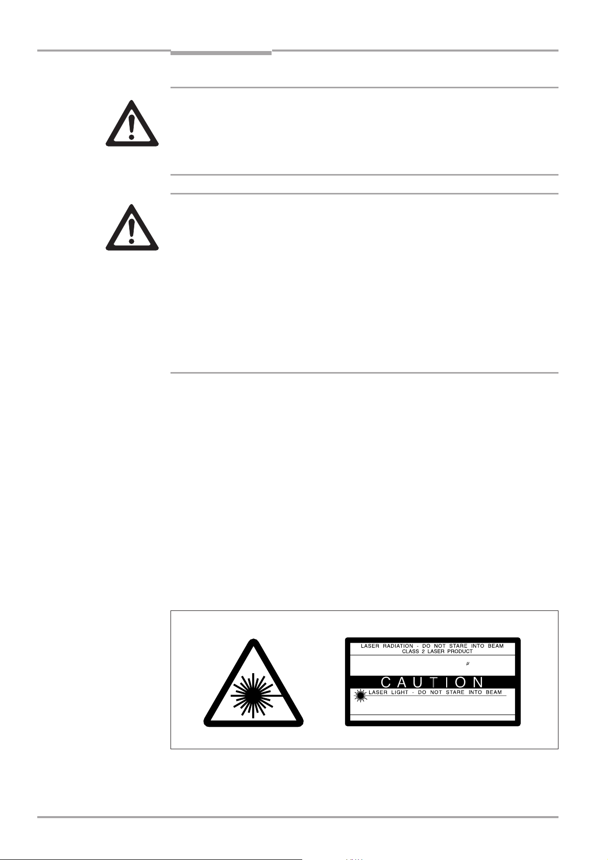
Laser beam can cause blindness!
The CLV uses a class 2 red-light laser. Looking directly at the laser beam can seriously damage your eyesight.
Ø As with sunlight, never look directly into the laser beam.
Ø Do not direct the laser beam at other persons.
Ø When mounting and aligning the CLV, avoid reflections caused by reflective surfaces.
Ø Do not open the housing.
Opening the housing does not deactivate the laser diode.
Ø Observe the most recent laser specifications (DIN EN 60825-1, latest version).
Laser power
The laser operates at a wavelength of λ =650 nm (visible red light). The power output at
the reading window is max. 2.8 mW.
The emitted radiation is not dangerous to human skin.
Laser warnings
The laser warning labels for Europe (Fig. 2-1) are attached at the following positions on
the CLV:
• The laser warning symbol on line scanners is positioned beside the reading window on
the front side of the device. The GB/US laser warning is located on the side containing
the electrical connections.
• The laser warning symbol on line scanners with oscillating mirror is located above the
reading window, on the cover of the mirror. The GB/US laser warning is located on the
side containing the electrical connections.
mW
2,8
56
650
mW
us
nm
2,8
111
650
s
nm
Fig. 2-1: Laser warning plates on the CLV
Max. output radiation:
Pulse duration:
Emitted wavelength:
EN 60825-1: 1994 + A11 : 1996
CLASS II LASER PRODUCT
Max. Output:
Pulse duration:
Wavelength:
Compiles with 21 CFR 1040.10
2-2
© SICK AG · Auto Ident · Germany · All rights reserved 8 008 796/0000/15-10-99

Operating Instructions
CLV 490 Bar Code Scanners
Safety information
Chapter 2
Note
Explanation
The device is supplied with an additional set of laser warning labels in German/US English
and French/US English. If necessary, these can be used to cover the GB/US warnings.
If the CLV is installed in a machine/panel with the result that the laser warning
plates are no longer visible, additional warnings (not included in the scope of delivery) must be provided on the machine beside the emergence aperture of the laser
beam.
Internal protective circuits
The CLV is equipped with monitoring circuits that deactivate the laser diode in the event of
a malfunction. Activation and deactivation of the laser diode is controlled by the reading
pulse trigger.
A safety circuit (timer) automatically deactivates the laser diode in Reading mode (“Sensor
input” and “Serial interface” trigger mode) if the reading interval has not ended after 10
minutes. However, it does not end the reading interval. In this case, the CLV outputs the
message:
“Laser safety timeout”
on the terminal interface. The reading interval must be terminated by resetting the trigger
signal. The laser diode is activated again by the next reading trigger.
In the Percentage Evaluation mode, Adjusting mode and Show CP-limits as well as in
the “free-running“ reading mode the laser diode is constantly activated.
2.4 Quick stop and quick restart
2.4.1 Stopping the CLV
Ø Switch off the power supply.
This can result in loss of the following (at the most):
• the application-specific parameter set, if it was stored temporarily in the CLV
• the last reading result
• daily operating data
(operating hours counter, trigger count, good read count, maximum duration trigger,
minimum duration trigger, average identification quality)
2.4.2 Restarting the CLV
Ø Switch on the power supply.
The CLV resumes operation with the parameter set that was last stored permanently
and resets the daily operating data.
2.5 Environmental information
The CLV is designed to cause minimum impact on the environment. It does not contain
any silicone-based materials and, therefore, does not represent any problems for paint
sprayers in paint shops, for example.
© SICK AG · Auto Ident · Germany · All rights reserved8 008 796/0000/15-10-99
2-3

Chapter 2
Safety information
Operating Instructions
CLV 490 Bar Code Scanners
2.5.1 Power requirements
The power requirements depend on the variants:
• the line scanner has a typical power consumption of 9 W and max. 16 W
• the line scanner with oscillating mirror has a typical power consumption of 9 W and max.
18 W
• the line scanner equipped with an integrated heater has a typical power consumption of
75 W and max. 90 W
• the line scanner with oscillating mirror equipped with an integrated heater has a typical
power consumption of 75 W and max. 100 W
The values are given for devices with disconnected switching outputs.
2.5.2 Disposal after removal from service
Always dispose of irreparable devices in a manner that is not harmful to the environment
and in accordance with the applicable national waste disposal regulations. The CLV can be
separated into recyclable secondary raw materials and special-category waste (electronic
scrap).
See also Section 7.3, Page 7-2.
SICK AG currently does not accept delivery of unusable or irreparable devices.
2-4
© SICK AG · Auto Ident · Germany · All rights reserved 8 008 796/0000/15-10-99

Operating Instructions
CLV 490 Bar Code Scanners
Product description
3 Product description
3.1 Design
3.1.1 Scope of delivery
The CLV is supplied with the following in the packing:
• an information sheet (notes on device) with terminal diagram and Quick Start instruc-
tions
• an additional set of Class 2 laser warning labels (self-adhesive) in German/US English
and French/US English.
Depending on the number of devices ordered, one or more sets of technical documen-
tation comprising:
• These CLV 490 Operating Instructions in English and German
• A set of DOS-formatted disks (3.5 inch) containing the CLV-Setup program for Win-
dows™, the online help system CLV-Setup Help, and the HTML browser I-ViewPro™
Chapter 3
Section 10.11, Page 10-41, contains an overview of the available accessories, connection
modules, cables, and connectors, as well as sensors for generating the reading pulse.
3.1.2 Variants
The CLV is currently available in the following variants:
Type Part. no. Scanning method Reading window Heater
(red light)
CLV 490-0010 1 016 958 Line scanner end no
CLV 490-1010 1 016 959 Line scanner with side no
oscillating mirror
CLV 490-0011 1 016 960 Line scanner end yes
CLV 490-1011 1 016 961 Line scanner side yes
with oscillating mirror
Table 3-1: CLV variants
3.1.3 System requirements
CLV without heater
The following are required to start up and operate the CLV:
1. A SICK Connection Module from the AMV/S 60 or AMV 30 series to provide the
power supply and connect the data and function interfaces.
Available types:
- For connection one CLV:
AMV 60-011 (no. 1 017 134) for 18 ... 30 V DC,
AMS 60-013 (no. 1 017 139) for 230 V AC 50 Hz/24 V DC and
AMS 60-012 (no. 1 017 140) for 115 V AC 50/60 Hz/24 V DC
- For connecting two CLVs: AMV 30-071 (no. 1 017 391) for 18 ... 30 V DC.
© SICK AG · Auto Ident · Germany · All rights reserved8 008 796/0000/15-10-99
3-1

Chapter 3
Product description
Operating Instructions
CLV 490 Bar Code Scanners
- or -
Alternatively, a non-SICK device with a voltage output of 18 ... 30 V DC pursuant to
IEC 742 (functional extra-low voltage) and a minimum power output of 20 W.
Cable no. 2 020 264 (3 m) with 15-pin D Sub HD connector and one open end
for connecting the CLV to the external power pack.
2. The following operating voltages/power output values:
- AMV 60-011: 18 ... 30 V DC (to IEC 742), min. 20 W
- AMV 30-071: 18 ... 30 V DC (to IEC 742), min. 40 W
- AMS 60-013: 230 V AC ±10% 50 Hz
- AMS 60-012: 115 V AC ±10% 50/60 Hz
3. With external clock pulse supply via the “Sensor” switching input: a suitable reading
pulse sensor for signaling an object with a bar code, e.g. a photoelectric reflex switch.
4. With object distance detection via the switching inputs “IN 0 ... IN 4”: suitable sensors
for multi-stage dynamic focus control, e.g. photoelectric reflex switches.
5. A PC with Windows 95™, Windows 98™, or Windows NT™ and a serial port (COM x)
6. An RS 232 data connection cable with two 9-pin D Sub sockets for connecting the PC
to the terminal interface of the CLV in the Connection Module, e.g. no. 2 014 054.
Pin 2 (RxD) and Pin 3 (TxD) are crossed
7. An HTML browser, e.g. Netscape Navitagator™, or the I-ViewPro™ browser supplied
with the device (see Section 3.1.1, Page 3-1) for using the online help system CLV-
Setup Help
8. The appropriate bus connection module BMV/BMH (available on request) for connecting the CLV to the Interbus-S, Profibus DP, or the Device Net
CLV with heater
The following are required to start up and operate the CLV:
1. A SICK Connection Module from the AMV 100 or AMV 200 series to provide the
power supply and connect the data and function interfaces.
Available types:
- For connecting one CLV: AMV 100-011 (no. 6 021 105) for 24 V DC
- For connecting two CLVs: AMV 200-011 (no. 6 021 106) for 24 V DC
- or -
Alternatively, a non-SICK power supply unit with a voltage output of
24 V DC +20%/-10% to IEC 742 (functional extra-low voltage) and a minimum
power output of 100 W.
Cable no. 2 020 264 (3 m) with 15-pin D Sub HD connector and one open end
for connecting the CLV to the external power pack.
3-2
2. The following operating voltages/power output values:
- AMV 100-011: 24 V DC +20%/-10% (pursuant to IEC 742), min. 100 W
- AMV 200-011: 24 V DC +20%/-10% (pursuant to IEC 742), min. 200 W
3. See pos. 3 under “CLV without heater”
© SICK AG · Auto Ident · Germany · All rights reserved 8 008 796/0000/15-10-99
Operating Instructions
CLV 490 Bar Code Scanners
Product description
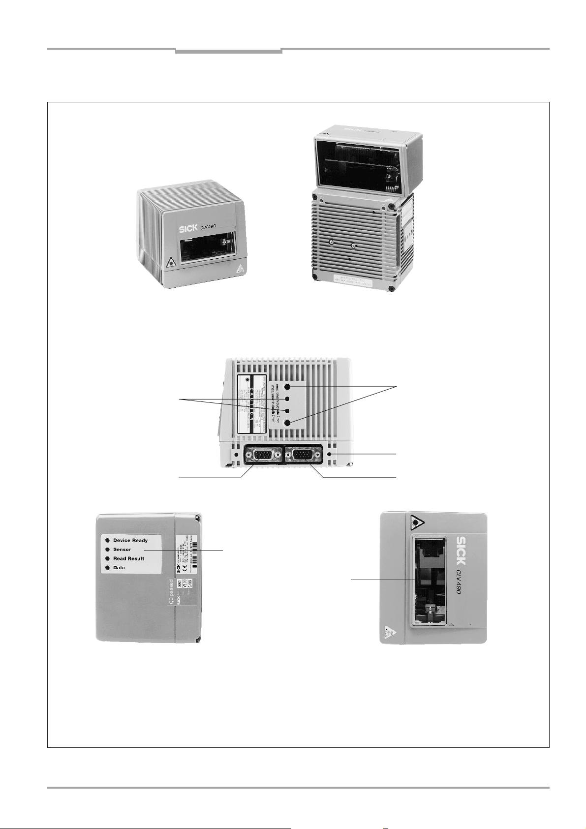
3.1.4 Layout
Chapter 3
Line scanner
(end reading window)
Line scanner with oscillating mirror
(side reading window)
Key:
Drilled hole, ∅ 3.6 mm, 6 mm
deep
Tapped blind hole M6, 7 mm
deep, for securing the device
Fig. 3-1: CLV 490
Tapped blind hole M4,
10 mm deep, for connector
cover
“Host/Term” connector
© SICK AG · Auto Ident · Germany · All rights reserved8 008 796/0000/15-10-99
“I/O” connector
LEDs
Reading window
3-3
Chapter 3
Product description
Operating Instructions
CLV 490 Bar Code Scanners
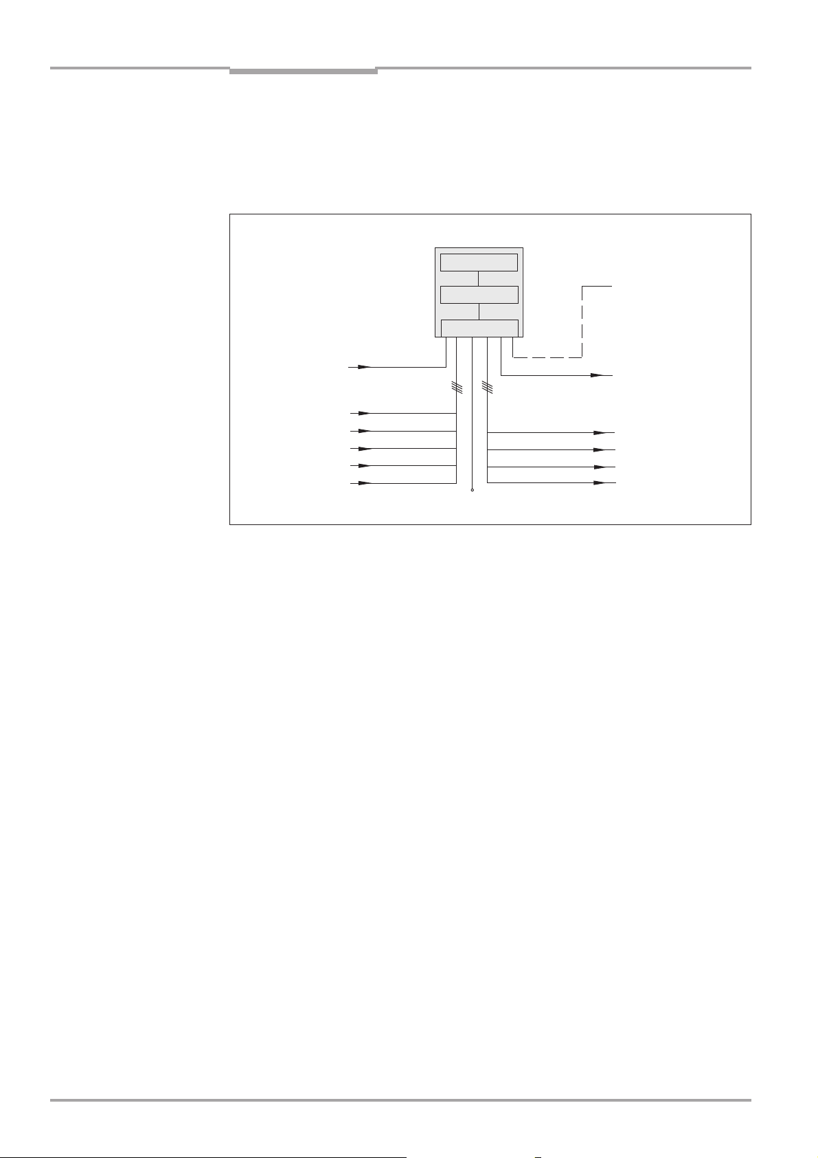
3.2 Method of operation
The CLV first scans the bar code with a scan line and then decodes it. The data is forwarded via the serial host interface to a host/PC for further processing. An overview of the
CLV functions is provided in Fig. 3-2.
CLV 490
Photoelectric
switch
Reading pulse
Signal*
Focus control
Trigger one-shot
Conveyor
increment
* if required
Fig. 3-2: Block diagram: CLV functions
“Sensor”
“IN 0”
“IN 1”
“IN 2”
“IN 3”
“IN 4”
Scanner
Decoder
Interface
V
S
“Terminal”
“Host”
“Result 1”
“Result 2”
“Result 3”
“Result 4”
Terminal
Operation
Parametrization
etc.
HOST
Further processing
of reading result
Status displays
e.g. Device Ready
e.g. Good read
e.g. No read
e.g. Match 1
The CLV is equipped with two decoders:
• The SMART decoder (SICK Modular Advanced Recognition Technology) for decoding
bar codes with small code height, bar codes that are dirty or damaged, as well as bar
codes that are tilted excessively (azimuth angle)
• The tried-and-tested standard decoder of the CLV series
The CLV derives useful diagnosis data from the reading process and transfers it to the
host. It also records operating data that can be interrogated at any time. The quality of
the read can be checked in percentage evaluation mode.
To start the reading process when an object is located in the reading field, the CLV
requires a suitable trigger. This opens a time window (“reading interval”) in the CLV. In the
default configuration, this trigger is supplied by an external reading pulse sensor. Alternative trigger sources include free-running mode or a command via the host interface (for
more complex applications: OTC triggers).
The current operating status is indicated by four LEDs.
If the trigger is supplied externally, the “Sensor” switching input instructs the CLV to start
the reading process. The five switching inputs “IN 0 ... IN 4” switch the focus position in
response to certain events, as an alternative to the autofocus function. The inputs “IN 3”
and “IN 4” can also be assigned special functions. The four switching outputs “Result 1
... Result 4” can be assigned different functions for displaying the result status and also
control external devices, such as a PLC.
The CLV is operated and configured via the terminal interface (auxiliary interface) using
the CLV Setup software or via the host interface/terminal interface using command
strings.
3-4
© SICK AG · Auto Ident · Germany · All rights reserved 8 008 796/0000/15-10-99
Operating Instructions
CLV 490 Bar Code Scanners
Product description
Chapter 3
System, warning, and error messages help you configure the device and locate the source
of errors during startup and reading mode.
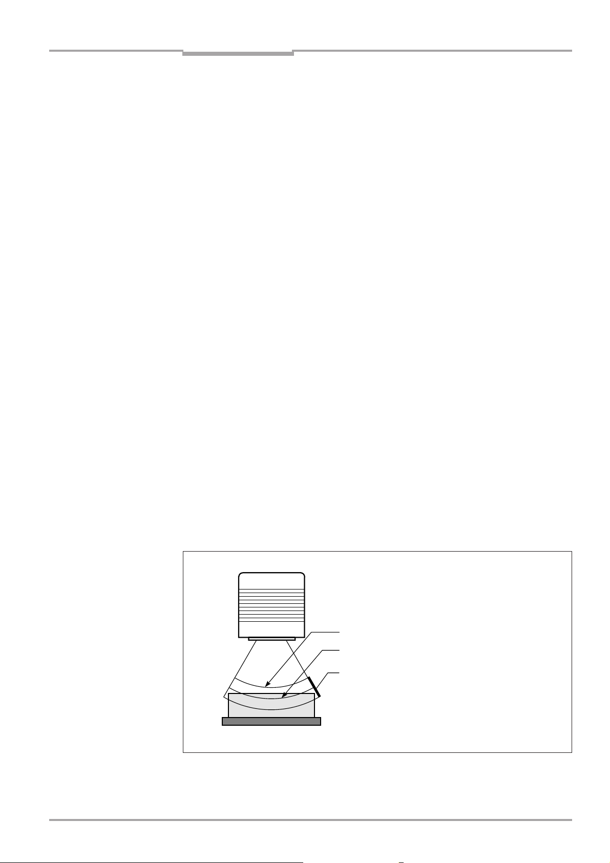
3.2.1 Autofocus function
The autofocus function enables the CLV to detect the distance of an object during the
reading process, without the need for external sensors, and then adjust the focus position
automatically to the reading plane of the bar code. In order to do so, the CLV measures
the object distance each time in its visible range in front of the reading window and
internally creates a distance profile. Following this, it positions the focus on the object.
3 operating modes are provided for various applications:
• Minimum distance: the CLV focuses on the minimum distance in the distance profile
and ignores the background in the visible range. Application: with unobstructed view of
the object without any surrounding objects protruding into the reading plane.
• Differential background: the distance profile of the visible range background is pro-
grammed (teach-in) in the CLV without any objects present. During the reading process,
the CLV then focuses on the object which it recognizes by comparing it to the distance
profile of the background. Application: with unobstructed view of the object restricted by
other objects that protrude into the reading plane.
• Differential background and tracking: if several objects with different distances are
positioned in the reading field at the same time (distance conflict), the CLV focuses on
the object that is nearest to but has not exceed its internal focus switchover point.
Application: in OTS operation (applications with tracking by the Omni Tracking Controller
OTC 400)
The distance profile of the background can also be displayed. The visible range is defined
by the autofocus range, the aperture angle, and (in the case of line scanners with oscillating mirror) also by the angle of deflection. The park setting of the focus position, from
which the device focuses for each read, can be specified in addition to a time or positionrelated delay (timeout or hysteresis). If necessary, an offset can be defined for the focus
position to be set by the measurement. The depth of field, which radiates in the direction
of the scan line and is caused by the V-principle of the beam deflection, is optimized as a
result (Fig. 3-3).
Measured distance
Optimium focus position:
measured distance plus offset for maximum
Depth of field (DOF)
Fig. 3-3: Optimizing the depth of field for the object
© SICK AG · Auto Ident · Germany · All rights reserved8 008 796/0000/15-10-99
3-5
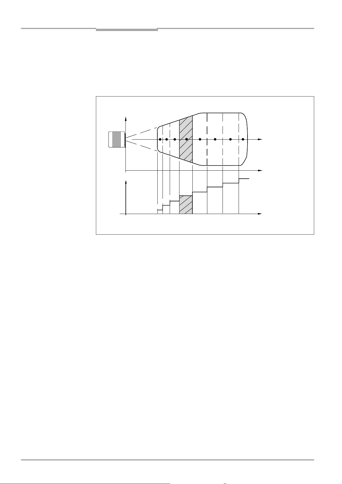
Chapter 3
Product description
Operating Instructions
CLV 490 Bar Code Scanners
3.2.2 Event-controlled dynamic focus control
As an alternative to the autofocus function, the CLV can switch its focus position in response to certain events and thus dynamically cover a large reading range. A maximum of
eight reading ranges can be defined as distance configurations for this purpose and
approached consecutively in reading mode (Fig. 3-4).
Reading
field
height
123 5 8
Focus
position
DC 2
DC 1
DC = Distance Configurations
Fig. 3-4: Dynamic focus control: classification of the reading range in distance configurations
DC 3
4
DC 4
DC 5
6 7
DC 6
DC 7
DC 8
Focus
position
Reading
distance
Reading
distance
The switchover takes place in response to changes in the object distance (with reads from
above: object height detection). The trigger source for the switchover is a signal combination at the switching inputs “IN 0 ... IN 4”, a command on the host interface or the integrated timer (e.g. for search mode). Additional in the case of the line scanner with
oscillating mirror also the oscillating mirror reversal points. The distance configurations are
assigned to the swichover sequence by means of a programmable assignment table. The
distance measurement of the autofocus function can be used to define the distance
configurations.
3-6
3.2.3 Scan procedure variants
Line scanner (standard device)
Generates a scan line; due to the V-principle of the beam generation, the reading field
height (the useful length of the scan line for evaluation purposes) is dependent on the
reading distance.
Line scanner with oscillating mirror
The oscillating mirror also deflects the scan line perpendicularly to the scan direction at
both sides around the neutral position with a low oscillating frequency. As a result, the CLV
can also scan larger areas for bar codes. Due to the V-principle of beam generation, the
reading field height is dependent on the reading distance.
In addition to parking and simple deflection with maximum amplitude, optimized oscillating
mirror functions are also available:
• Oscillating with variable deflection amplitude per distance configuration
• One-shot: one-off, defined deflection per reading pulse (forward and return phase).
© SICK AG · Auto Ident · Germany · All rights reserved 8 008 796/0000/15-10-99

Operating Instructions
CLV 490 Bar Code Scanners
Product description
Chapter 3
3.2.4 Additional components
Heater
The CLV can be permanently equipped with a heater for applications involving temperatures up to max. -35 °C (e.g. in a freezer). The design, technical data, and power-up
behavior of the CLV are described in Section 10.4, Page 10-20.
External parameter memory
The external parameter memory is located in a connector cover which, when mounted,
covers the two electrical terminals on the CLV (IP 65). The parameter memory saves you
time when a CLV is replaced locally by providing a copy of the current parameter set. In
other words, you do not have to configure the new device.
For information on applications and operating procedures, see Section 10.3, Page 10-16.
3.3 Indicators and control elements
3.3.1 Control elements
The CLV is operated and configured via the terminal interface (auxiliary interface) using the
CLV Setup program or using command strings sent via the host interface/terminal interface. A variety of parameter options allow you to adapt the device to a wide range of
applications.
The following can be defined:
• The configuration of the code types
• The read, evaluation, and output properties
• The communication parameters of the host interface
• The structure of the data output string for “Good read” and “No read” on the host
interface
• The function of the terminal interface
Section 10.6, Page 10-23 describes the procedure for installing the CLV-Setup program
and explains how to use it. The parametrization (configuration) procedure is explained in
Section 6.4, Page 6-5.
3.3.2 Function of the LEDs
Four LEDs indicate the operating status, activity of the laser diode, reading result status,
and data transfer on the host interface. The LEDs are located on the rear of the device
(Fig. 3-5).
Fig. 3-5: LEDs
© SICK AG · Auto Ident · Germany · All rights reserved8 008 796/0000/15-10-99
Device Ready
Sensor
Read Result
Data
3-7

Chapter 3
Product description
CLV 490 Bar Code Scanners
If the optional external parameter memory is connected, the LEDs also indicate whether
the memory was successfully accessed.
The meaning of the LEDs in the various operating modes/functions is shown in Table 3-2
and Table 3-3.
CLV without external parameter memory
Operating mode LED Display Function
Start Device Ready green • Lights up after power-up if the self-test was successful
Subsequent behavior depends on selected start option:
Start option: “S
• Lights up constantly (CLV has loaded internal parameter set)
Start option: “S
• Lights up constantly (CLV has loaded internal parameter set)
Start option: “S
• Blinks constantly together with the Read Result LED
(CLV has loaded internal parameter set)
Read Result green Start option: “S
• Blinks constantly together with the Device Ready LED
TAR T WITH EXTERNAL PARAMETERS” (default):
TAR T WITH INTER NAL PARAMETERS”:
TAR T WITH COPY INTERN -> EXTE RN”:
TAR T WITH COPY INTERN -> EXTE RN”:
Operating Instructions
1)
1)
Reading mode Device Ready green • Lights up constantly
• Extinguishes with new operating mode/function
Sensor green • Lights up if reading diode active.
(The laser diode is activated/deactivated by reading pulse)
• Lights up constantly in free-running mode, since laser diode is always
active
Read Result green LED is linked to the Result 2 switching output and indicates the selected
result status for the defined pulse duration of the output.
• Lights up after a successful read (Good Read)
• Lights up if the match code comparison is active, the bar code read
matches the specified match code(s) and the corresponding
result status output is selected for the Result 2 output
Data yellow • Blinks while the CLV transfers data to the host on the host interface
Percentage Sensor green • Lights up constantly, as free-running mode is active
evaluation Read Result green Behavior depends on the reading quality:
• Extinguishes if reading rate < 30%
• Blinks twice a second if reading rate 30% ... 70%
• Blinks five times a second if reading rate 70% ... 90%
• Lights up constantly if reading rate > 90%
Adjusting mode Sensor green • Lights up constantly, as free-running mode is active
Show CP limits Sensor green • Blinks bright/dark alternately, in the frequency with which the
scan line is (partially) masked out
1) Set the start option to “START WITH INTERNAL PARAM ETERS” on the “DEVICE CONFIGU RATION” tab in the CLV-Setup program. Download to CLV!
Table 3-2: Meaning of LEDs: CLV without external parameter memory
3-8
© SICK AG · Auto Ident · Germany · All rights reserved 8 008 796/0000/15-10-99

Operating Instructions
Product description
CLV 490 Bar Code Scanners
CLV with external parameter memory connected
Operating mode LED Display Function
Start Device Ready green • Lights up after power-up if the self-test was successful
Subsequent behavior depends on selected start option:
Start option: “S
• Blinks for approx. 10 s before lighting up constantly.
(CLV has loaded the parameter set from the external
parameter memory and starts Reading mode straight away)
• Blinks for approx. 10 s together with the Read Result LED,
then lights up constantly.
(CLV has loaded the parameter set from the external parameter memory
with tolerated errors
• Lights up constantly.
(CLV could not find an external parameter memory and loads the internal
parameter set instead)
• Blinks constantly together with the Read Result LED
(The external parameter memory is either empty, contains the parameter
set for a different CLV type, or is corrupt.
CLV has loaded internal parameter set. It starts Reading mode
but does not output data over the host interface)
Start option: “S
• Lights up constantly (CLV has loaded internal parameter set)
Start option: “S
• Blinks alternately with the Read Result LED for approx. 10 s
before lighting up constantly.
(CLV has successfully copied the internal parameter set to the external
memory and has reset the start option to “S
CLV has loaded the internal parameter set.
• Blinks constantly together with the Read Result LED
(The external parameter memory is either not connected or corrupt, or
the parameter set is too large to be copied).
CLV has loaded the internal parameter set.
Read Result green Start option: “S
• Blinks for approx. 10 s together with Device Ready
• Blinks constantly together with the Device Ready LED
Start option: “S
• Blinks alternately with Device Ready LED for approx. 10 s (see above) or
• Blinks constantly together with the Device Ready LED2) (see above)
TAR T WITH EXTER NAL PARAMETERS” (default):
1)
and starts Reading mode straight away)
TAR T W ITH INTERNAL PARAMETERS”:
TAR T WITH COPY INTER N -> EXTER N”:
TA RT WITH EXTERNAL PARAMETERS”).
TAR T WITH EXTERNAL PARAMETERS” (Default):
TAR T WITH COPY INTER N -> EXTER N”:
Chapter 3
2)
.
2)
1)
LED (see above) or
2)
(see above)
Reading mode Device Ready green • Lights up constantly
• Extinguishes with new operating mode/function
Sensor green • Lights up if reading diode active.
(The laser diode is activated/deactivated by the reading pulse)
• Lights up constantly in free-running mode, since the laser diode is
constantly active
Read Result green LED is linked to the Result 2 output and indicates the selected result
status for the defined pulse duration of the output.
• Lights up after a successful read (Good Read)
1) We recommend that you check the parameter set manually, e.g. by printing out the entire configuration. For troubleshooting, see also Section 8.3.2, Page 8-5
2) Stops blinking when you switch from Reading mode to Parameter mode
Table 3-3: Meaning of LEDs: CLV with external parameter memory
© SICK AG · Auto Ident · Germany · All rights reserved8 008 796/0000/15-10-99
3-9

Chapter 3
Operating mode LED Display Function
Reading mode Read Result green • Lights up if the match code comparison is active, the bar code read
(contd.) (contd.) matches the specified match code(s) and the corresponding result
Data yellow • Blinks while the CLV transmits data to the host over the host interface
Percentage Sensor green • Lights up constantly, since free-running mode is active
evaluation Read Result green Behavior dependent on the reading quality:
Adjusting mode Sensor green • Lights up constantly, since free-running mode is active
Show CP limits Sensor green • Blinks bright/dark alternately, in the frequency with which the
Table 3-3: Meaning of LEDs: CLV with external parameter memory (continued)
Product description
output is selected for the Result 2 output
• Extinguishes if reading rate < 30%
• Blinks twice a second if reading rate 30% ... 70%
• Blinks five times a second if reading rate 70% ... 90%
• Lights up constantly if reading rate > 90%
scan line is (partially) masked out
Operating Instructions
CLV 490 Bar Code Scanners
3-10
© SICK AG · Auto Ident · Germany · All rights reserved 8 008 796/0000/15-10-99
 Loading...