

SICK CLV 490 Series, CLV 490-1011, CLV 490-0010, CLV 490-0011, CLV 490-1010 Operating Instructions Manual
Page 1

O
PERATING
I
NSTRUCTIONS
CLV 490
Bar Code Scanner
Advanced Line
PRELIMINARY
Page 2

Software versions
Operating Instructions
CLV 490 Bar Code Scanners
Software versions
Software/Tool Function Version
CLV 490 Firmware from V 0.90 0000
CLV-Setup User interface (windows-based) from V 2.70 J645
CLV-Setup Help Online help (HTML) from V 1.1
I-ViewPro
TM
Offline browser (HTML) from V2.38
I-2
Windows 95™, Windows 98™, Windows NT™ and Internet Explorer™ are registered
trademarks or trademarks of the Microsoft Corporation in the USA and other countries.
Netscape Navigator™ is a registered trademark of the Netscape Communications
Cooperation, USA.
I-ViewPro™ is a registered trademark of EnReach Technology, Inc., USA.
© SICK AG · Auto Ident · Germany · All rights reserved 8 008 796/0000/15-10-99
Page 3

Operating Instructions
CLV 490 Bar Code Scanners
Quick Finder
CLV 490 Bar code Scanners
Ø Quick Finder
• What is delivered with the device
Ø Section 3.1.1 Scope of supply, Page 3-1
• IMPORTANT!
Ø Chapter 2. Safety instructions, Page 2-1
• Mounting the device at the reading station
Ø Chapter 4. Installation, Page 4-1
• Connecting the device
Ø Chapter 5. Electrical installation, Page 5-1
• Overview of the device and its functions
Ø Chapter 3. Product description, Page 3-1
Ø Section 6.2 Default settings, Page 6-1
Ø Section 6.5 Operating modes and outputting the reading result, Page 6-19
Ø Chapter 9. Technical data, Page 9-1
Ø Section 10.3 External parameter memory, Page 10-16
• Starting the device with the default settings
Ø Section 6.3 Quick start, Page 6-3
• Installing the CLV Setup program
Ø Section 10.6 Installing and operating the CLV Setup program, Page 10-23
• Adapting the device to the reading application
Ø Section 6.4 Configuring (parameterizing) the CLV, Page 6-5
• Troubleshooting
Ø Chapter 8. Troubleshooting, Page 8-1
• Finding information
Ø Contents, Page E-5
Ø Index, Page 10-55
© SICK AG · Auto Ident · Germany · All rights reserved8 008 796/0000/15-10-99
I-3
Page 4

Quick Finder
Operating Instructions
CLV 490 Bar Code Scanners
Installation procedure (overview)
1. Check the delivery to make sure that none of the components is missing.
2. Mount the CLV at the reading station and align it with the object carrying the bar code.
3. Mount the AMV/S 60 Connection Module.
4. Connect the CLV to the AMV/S 50 Connection Module using the two cables
no. 2 020 302.
Alternatively, connect the device to the AMV/S 60 via the external parameter memory.
5. Connect the reading pulse sensor to the “Sensor” switching input in the AMV/S 60.
6. Connect the host to the host interface in the AMV/S 60.
Adjust the AMV/S 60 to the host interface type of the CLV.
7. Switch on the power supply to the AMV/S 60.
The “Device Ready” LED lights up after the CLV has started.
CLV with external parameter memory connected:
The “Device Ready” LED and the “Read Result” LEDs blink after the CLV has started.
The CLV is not ready to start reading. See step 11.
Line scanner with oscillating mirror:
In the default setting, the CLV deflects the scan line around the position CW =50 with
a frequency of 1 Hz and an oscillating amplitude of ±20° (±40 CW).
8. Switch on your PC and start WindowsTM (minimum requirement: Windows 95TM)
9. Install the CLV Setup software, online CLV Setup Help and, if necessary, the HTML
browser I-ViewProTM on your PC.
10. Connect the PC to the terminal interface of the CLV. To do so, connect the RS 232
cable (e.g. no. 2 014 054) to the Service connector in the AMV/S 60.
11. Start the CLV Setup program.
CLV Setup establishes communication with the CLV and uploads the parameter set.
The parameters are then displayed on the tabs.
CLV with external parameter memory connected:
First download the CLV parameter set to the external memory.
Disconnect the AMV/S 60 briefly from the power supply to restart the CLV.
12. Carry out a test read using test bar codes (clock the CLV accordingly).
Display the reading result in the Terminal Emulator window of the CLV Setup program.
13. Configure the CLV for the application using the settings on the tabs in CLV Setup. Copy
(download) the modified parameter set to the CLV temporarily.
Do not switch off the power to the AMV/S 60 (CLV)!
I-4
14. Test the application under realistic conditions.
15. Check whether the data is transmitted correctly between the CLV and host.
16. If necessary, correct and optimize the parameter values.
Copy (download) the parameter set permanently to the CLV.
CLV with external parameter memory connected:
Copy the modified parameter set to the external parameter memory.
17. Save the parameter set as a configuration file “*.scl” in the CLV Setup program.
The CLV can then be operated with the application-specific settings.
© SICK AG · Auto Ident · Germany · All rights reserved 8 008 796/0000/15-10-99
Page 5

Operating Instructions
CLV 490 Bar Code Scanners
Contents
Contents
1. Notes on this document ........................................................................................ 1-1
1.1 Purpose ...................................................................................................................................1-1
1.2 Target audience ....................................................................................................................1-1
1.3 Information content ............................................................................................................. 1-1
1.4 Symbols ................................................................................................................................... 1-2
2. Safety information ................................................................................................... 2-1
2.1 Authorized users...................................................................................................................2-1
2.1.1 Mounting and maintenance ..................................................................................... 2-1
2.1.2 Electrical installation and replacement................................................................. 2-1
2.1.3 Start-up, operation and configuration ...................................................................2-1
2.2 Intended use.......................................................................................................................... 2-1
2.3 General safety instructions and protection measures............................................ 2-1
2.4 Quick stop and quick restart ............................................................................................ 2-3
2.4.1 Stopping the CLV ......................................................................................................... 2-3
2.4.2 Restarting the CLV ....................................................................................................... 2-3
2.5 Environmental information ................................................................................................ 2-3
2.5.1 Power requirements ....................................................................................................2-4
2.5.2. Disposal after removal from service .....................................................................2-4
3. Product description ................................................................................................ 3-1
3.1 Design ...................................................................................................................................... 3-1
3.1.1 Scope of supply ............................................................................................................3-1
3.1.2 Variants............................................................................................................................ 3-1
3.1.3 System requirements ................................................................................................. 3-1
3.1.4 Layout............................................................................................................................... 3-3
3.2 Method of operation ........................................................................................................... 3-4
3.2.1 Autofocus function .......................................................................................................3-5
3.2.2 Event-controlled dynamic focus control ...............................................................3-6
3.2.3 Scan procedure variants ........................................................................................... 3-6
3.2.4 Additional components .............................................................................................. 3-7
3.3 Indicators and control elements ..................................................................................... 3-7
3.3.1 Control elements .......................................................................................................... 3-7
3.3.2 Function of the LEDs .................................................................................................. 3-7
4. Installation ................................................................................................................. 4-1
4.1 Installation sequence.......................................................................................................... 4-1
4.2 Preparations ........................................................................................................................... 4-1
4.2.1 Required components ................................................................................................4-1
4.2.2 Required accessories .................................................................................................4-1
4.2.3 Required auxiliary parts .............................................................................................. 4-1
4.2.4 Replacing the laser warning label ........................................................................... 4-2
4.2.5 Selecting the mounting location ............................................................................. 4-2
4.2.6 Mounting accessories ................................................................................................ 4-2
4.2.7 Distance between the CLV and the bar code ................................................... 4-4
4.2.8 Count direction of the code position CP and code angle CW ...................... 4-6
4.3 Mounting and adjusting the device................................................................................ 4-7
4.3.1 Mounting the CLV ........................................................................................................ 4-7
4.3.2 Adjusting the CLV ......................................................................................................... 4-8
4.3.3 Adjusting mode ............................................................................................................. 4-9
© SICK AG · Auto Ident · Germany · All rights reserved8 008 796/0000/15-10-99
I-5
Page 6

Contents
4.4 Mounting the external components ........................................................................... 4-10
4.4.1 Mounting the AMV/S 60 Connection Module ................................................ 4-10
4.4.2 Mounting the external reading pulse sensor ................................................... 4-10
4.4.3 Mounting the sensors for detecting the object distance ............................ 4-12
4.5 Dismantling the device .................................................................................................... 4-13
5. Electrical installation ............................................................................................. 5-1
5.1 Installation sequence ....................................................................................................... ... 5-1
5.1.1 SICK Connection Modules (overview) ................................................................. 5-1
5.2 Electrical connections and cables .................................................................................. 5-2
5.2.1 Wire cross-sections ..................................................................................................... 5-2
5.2.2 Prefabricated cables (overview) ............................................................................. 5-2
5.2.3 Connections/cables for the AMV/S Connection Module .............................. 5-3
5.2.4 Connections/cables for the Bus Connection Modules
BMV 10 and BMS 20 ................................................................................................. 5-4
5.2.5 Connections/cables for the external parameter memory
(connection to AMV/S or BMV 10/BMS 20) .....................................................5-5
5.2.6 Connections/cables for the connector cover
(connection to AMV 100/200 or BMV 10) ........................................................ 5-5
5.3 Connector pin assignment ................................................................................................ 5-6
5.3.1 Terminals on the CLV ................................................................................................. 5-6
5.3.2 External parameter memory no. 2 020 307 (accessory)/
Connector cover no. 2 021 298 (accessory) ................................................... 5-7
5.4 Preparations for electrical installation ........................................................................... 5-8
5.4.1 Requirements for the host interface ..................................................................... 5-8
5.4.2 Supply voltage ............................................................................................................... 5-8
5.4.3 Non-SICK power supply unit/connections without the
Connection Module ..................................................................................................... 5-9
5.5 Electrical installation procedure ................................................................................... 5-13
5.5.1 Individual steps .......................................................................................................... 5-13
5.5.2 Tools .............................................................................................................................. 5-13
5.5.3 Connecting the supply voltage ............................................................................. 5-13
5.5.4 Connecting the host interface .............................................................................. 5-14
5.5.5 Connecting the PC .................................................................................................... 5-15
5.5.6 Connecting the switching inputs .......................................................................... 5-16
5.5.7 Connecting the “Result 1” ... “Result 4” switching outputs ........................ 5-19
Operating Instructions
CLV 490 Bar Code Scanners
I-6
6. Operation ................................................................................................................... 6-1
6.1 Overview of steps for starting up the CLV ................................................................... 6-1
6.2 Default settings ..................................................................................................................... 6-1
6.2.1 Default settings of the line scanner CLV 490-0010/-0011 ......................... 6-2
6.2.2 Default settings of the line scanner with oscillating mirror
CLV 490-1010/-1011 ................................................................................................ 6-2
6.3 Quick start............................................................................................................................... 6-3
6.3.1 Switching the CLV on for the first time with the factory default settings ..6-3
6.3.2 Switching the CLV with external parameter memory connected on
for the first time with the factory default settings ............................................. 6-4
6.4 Configuring (parameterizing) the CLV ...........................................................................6-5
6.4.1 Configuring the CLV via the user interface of CLV Setup .............................. 6-5
6.4.2 Function of the tabs in CLV Setup (overview) ................................................... 6-6
6.4.3 Guide to parameterization menu ............................................................................6-9
6.4.4 Configuring the CLV with command strings ......................................................6-17
© SICK AG · Auto Ident · Germany · All rights reserved 8 008 796/0000/15-10-99
Page 7

Operating Instructions
CLV 490 Bar Code Scanners
Contents
6.5 Operating modes and outputting the reading result............................................. 6-19
6.5.1 Reading mode (standard operating mode) ..................................................... 6-19
6.5.2 Percentage evaluation ............................................................................................. 6-22
6.5.3 Adjusting mode .......................................................................................................... 6-23
6.5.4 Background teach-in ................................................................................................ 6-24
6.5.5 Show CP-limits ............................................................................................................ 6-25
6.5.6 Displaying and editing operating data ............................................................... 6-27
6.5.7 Reading diagnosis ..................................................................................................... 6-27
6.5.8 Monitor Host Interface ............................................................................................ 6-28
6.5.9 Auxiliary input .............................................................................................................. 6-30
6.5.10 Self-test ........................................................................................................................ 6-30
6.5.11 Executing CLV functions interactively ................................................................ 6-31
6.6 CLV messages ................................................................................................................... 6-32
6.6.1 Displaying messages ............................................................................................... 6-32
6.6.2 System messages .................................................................................................... 6-32
6.6.3 Warning messages ................................................................................................... 6-32
6.6.4 Error messages ......................................................................................................... 6-33
6.7 Switching off the CLV .......................................................................................................6-33
7. Maintenance .............................................................................................................. 7-1
7.1 Cleaning the CLV during operation ................................................................................ 7-1
7.2 Maintenance .......................................................................................................................... 7-2
7.3 Disposal................................................................................................................................... 7-2
8. Troubleshooting ....................................................................................................... 8-1
8.1 Overview of the possible errors and malfunctions ...................................................8-1
8.1.1 Mounting errors ............................................................................................................8-1
8.1.2 Electrical installation errors ....................................................................................... 8-1
8.1.3 Parameter errors ..........................................................................................................8-1
8.1.4 Malfunctions ..................................................................................................................8-1
8.2 Monitoring ............................................................................................................................... 8-1
8.3 Error messages .................................................................................................................... 8-2
8.3.1 CLV without external parameter memory ........................................................... 8-2
8.3.2 LED error messages for the external parameter memory ............................8-5
8.3.3 Messages for errors accessing the external parameter memory .............. 8-7
8.4 ST error status in the reading result of a bar code .................................................. 8-9
8.5 Troubleshooting ................................................................................................................. 8-11
8.5.1 General malfunctions: CLV not ready ................................................................ 8-11
8.5.2 Malfunctions in Reading mode: reading trigger errors ................................. 8-12
8.5.3 Malfunctions in Reading mode: result output errors .................................... 8-14
8.5.4 Malfunctions in Reading mode: errors in the result status output .......... 8-18
8.5.5 Malfunctions in Reading mode: oscillating mirror errors ............................. 8-19
8.6 Sick Support........................................................................................................................ 8-20
9. Technical data .......................................................................................................... 9-1
9.1 Data sheet CLV 490-0010 bar code scanner .......................................................... 9-1
9.2 Data sheet CLV 490-1010 bar code scanner........................................................... 9-2
9.3 Data sheet CLV 490-0011 bar code scanner .......................................................... 9-2
9.4 Data sheet CLV 490-1011 bar code scanner........................................................... 9-3
9.5 Dimensioned drawings - CLV ........................................................................................... 9-3
9.5.1 Line scanner (without/with heater) ........................................................................ 9-3
9.5.2 Line scanner with oscillating mirror (without/with heater) .............................9-4
© SICK AG · Auto Ident · Germany · All rights reserved8 008 796/0000/15-10-99
I-7
Page 8

Contents
10. Appendix .................................................................................................................. 10-1
10.1 Overview ............................................................................................................................... 10-1
10.2 Specification diagrams .................................................................................................... 10-2
10.2.1 Reading conditions for all diagrams ................................................................... 10-2
10.2.2 Overview diagrams ................................................................................................... 10-2
10.2.3 Reading performance data line scanner ........................................................... 10-3
10.2.4 Reading performance data line scanner with oscillating mirror ................ 10-9
10.3 Installing and operating the external parameter memory ................................ 10-16
10.3.1 Function ...................................................................................................................... 10-16
10.3.2 Installation and electrical connection ............................................................... 10-17
10.3.3 Operation ................................................................................................................... 10-17
10.3.4 Switching on the device for the first time .......................................................10-18
10.3.5 Adjusting the parameter set in the external parameter memory
after it has been downloaded to the CLV ...................................................... 10-18
10.3.6 Meaning of the LEDs ............................................................................................. 10-19
10.3.7 Error messages ....................................................................................................... 10-19
10.3.8 Replacing a CLV ....................................................................................................... 10-19
10.4 Optional heating .............................................................................................................. 10-20
10.4.1 Features .................................................................................................................... 10-20
10.4.2 Design ........................................................................................................................ 10-20
10.4.3 Function ..................................................................................................................... 10-20
10.4.4 Electrical connection ..............................................................................................10-21
10.4.5 Outdoor applications ..............................................................................................10-21
10.5 System messages ......................................................................................................... 10-22
10.5.1 CLV without external parameter memory ..................................................... 10-22
10.5.2 CLV with external parameter memory connected ..................................... 10-22
10.6 Installing and operating the CLV Setup program ................................................ 10-23
10.6.1 Preparations ............................................................................................................. 10-23
10.6.2 Installing the software ........................................................................................... 10-23
10.6.3 Starting CLV Setup ................................................................................................ 10-25
10.6.4 User interface ...........................................................................................................10-27
10.6.5 Functions ................................................................................................................... 10-28
10.6.6 CLV Setup Help ...................................................................................................... 10-28
10.6.7 Transferring parameter sets between CLV Setup and the CLV ............ 10-29
10.6.8 Unknown parameters ........................................................................................... 10-29
10.6.9 Log file in the Terminal Emulator ...................................................................... 10-30
10.6.10 Starting CLV Setup with an INI file as an argument .................................. 10-30
10.7 Calculating parameter values for setting the CLV ...............................................10-31
10.7.1 Calculating the number of scans (for standard decoders) ......................10-31
10.7.2 Calculating the start position and mirror speed for the forward
and return phase of the one-shot function ................................................... 10-33
10.7.3 Calculating the necessary bar code clearence if several
bar codes are read on each object ................................................................. 10-34
10.8 Tables ................................................................................................................................. 10-35
10.8.1 Calculating the code length of a bar code .................................................... 10-35
10.9 Special applications and procedures...................................................................... 10-36
10.9.1 Auxiliary input ........................................................................................................... 10-36
10.9.2 Daisy-chain configuration .................................................................................... 10-39
10.9.3 SICK network (RS 485) ....................................................................................... 10-39
10.9.4 Profibus DP ............................................................................................................... 10-39
Operating Instructions
CLV 490 Bar Code Scanners
I-8
© SICK AG · Auto Ident · Germany · All rights reserved 8 008 796/0000/15-10-99
Page 9

Operating Instructions
CLV 490 Bar Code Scanners
Contents
10.10 Replacing a CLV (copying the parameter set) ..................................................... 10-40
10.10.1 Downloading the parameter set ....................................................................... 10-40
10.10.2 Importing the parameter set from the external memory .......................... 10-41
10.11 Accessories ...................................................................................................................... 10-42
10.11.1 Mounting accessories .......................................................................................... 10-42
10.11.2 Connection modules............................................................................................. 10-42
10.11.3 Cables, external parameter memories and plug covers.......................... 10-43
10.11.4 Plug-in connections ............................................................................................... 10-44
10.11.5 Reading pulse generators ................................................................................... 10-44
10.11.6 Network controller ................................................................................................. 10-44
10.12 Dimensioned drawings of the accessories ........................................................... 10-45
10.12.1 Mounting bracket no. 2 013 824 .................................................................... 10-45
10.12.2 Articulated bracket no. 2 018 435 .................................................................. 10-45
10.12.3 Quick clamping device no. 2 016 110 ........................................................... 10-45
10.13 Supplementary documentation ................................................................................. 10-46
10.14 Glossary .............................................................................................................................. 10-47
10.15 Index ................................................................................................................................... 10-54
10.16 Bar code examples ....................................................................................................... 10-59
© SICK AG · Auto Ident · Germany · All rights reserved8 008 796/0000/15-10-99
I-9
Page 10

Contents
(blank page)
Operating Instructions
CLV 490 Bar Code Scanners
I-10
© SICK AG · Auto Ident · Germany · All rights reserved 8 008 796/0000/15-10-99
Page 11

Operating Instructions
CLV 490 Bar Code Scanners
AMV/S Connection Module with signal distribution/with additional power supply pack
BMV/S Bus Connection Module with signal distribution/with additional power supply pack
DOF Depth Of Field
EEPROM Electrically Erasable Programable Read Only Memory
HTML Hyper Text Markup Language (page-description language on the internet)
ROM Read Only Memory
Figures and tables
Abbreviations
CLV Code-Leser V-Prinzip (Code Reader V-Prinziple). The CLV 490 bar code scanners are
abbreviated to CLV in this documentation, except where a distinction is necessary.
DC Distance Configuration
LED Light Emitting Diode
PLC Programmable Logic Controller
RTF Rich Text Format (standard document format with format descriptions)
Tables
Tab. 3-1: CLV variants ............................................................................................................................................... 3-1
Tab. 3-2: Meaning of LEDs: CLV without external parameter memory ............................................... 3-8
Tab. 3-3: Meaning of LEDs: CLV with external parameter memory ....................................................... 3-9
Tab. 4-1: Permissible reading angles between the scan lines and bar code..................................... 4-5
Tab. 5-1: Connection Modules for the CLV ...................................................................................................... 5-1
Tab. 5-2: Cables for connecting the CLV ........................................................................................................... 5-2
Tab. 5-3: Pin assignment of the 15-pin D Sub HD Host/Term connector ...........................................5-6
Tab. 5-4: Pin assignment of the 15-pin D Sub HD I/O socket ................................................................. 5-6
Tab. 5-5: Pin assignment of the 15-pin D Sub HD Host/Term cable connector .............................. 5-7
Tab. 5-6: Pin assignment of the 15-pin D Sub HD I/O cable socket ..................................................... 5-7
Tab. 5-7: Maximum cable lengths between the CLV and host ................................................................ 5-8
Tab. 5-8: Power consumption of the CLV ......................................................................................................... 5-8
Tab. 5-9: Power-up delay as a function of the device number GN ........................................................ 5-8
Tab. 5-10: Wire color assignment of the cable no. 2 020 303.................................................................. 5-9
Tab. 5-11: Wire color assignment of the cable no. 2 020 264............................................................... 5-10
Tab. 5-12: Wire color assignment of cable 1 for external parameter memory no. 2 020 981.. 5-11
Tab. 5-13: Wire color assignment of cable 2 for external parameter memory no. 2 020 981.. 5-11
Tab. 5-14: Wire color assignment cable 1 for connector cover no. 2 021 267 ............................... 5-12
Tab. 5-15: Wire color assignment cable 2 for connector cover no. 2 021 267 ............................... 5-12
Tab. 5-16: Communication parameters for the host interface (default setting) ............................... 5-14
Tab. 5-17: Characteristic data of the “Sensor” switching input ............................................................... 5-16
Tab. 5-18: Pin and terminal assignment for “IN 0 ... IN 4“ switching inputs ........................................5-17
Tab. 5-19: Characteristic data of the “ IN 0 ... IN 4” switching inputs ................................................... 5-18
Tab. 5-20: Dynamic focus control: switching inputs/distance configuration assignment table.. 5-18
Tab. 5-21: Combination of the functions of the “IN 0 ... IN 4“ switching inputs................................ 5-19
Tab. 5-22: Pin and terminal assignment for “Result 1 ... Result 4“ switching outputs.................... 5-20
Tab. 5-23: Characteristic data of the “Result 1 ... Result 4” switching outputs................................. 5-20
Tab. 6-1: Extract: Default parameter settings of the line scanner CLV 490-0010/-0011 .......... 6-2
© SICK AG · Auto Ident · Germany · All rights reserved8 008 796/0000/15-10-99
I-11
Page 12

Figures and tables
Tab. 6-2: Extract: Default parameter settings of the line scanner with oscillating mirror
CLV 490-1010/-1011 ............................................................................................................................ 6-2
Tab. 6-3: Reading distances for default settings ........................................................................................... 6-4
Tab. 6-4: Guide: Parameterizing autofocus mode ......................................................................................... 6-9
Tab. 6-5: Guide: Parameterizing the event-controlled focus control function ................................. 6-10
Tab. 6-6: Guide: Parameterizing oscillating mirror functions .................................................................. 6-11
Tab. 6-7: Guide: Parameterizing the reading trigger source ................................................................... 6-15
Tab. 6-8: Guide: Settings for evaluating identical bar codes ................................................................. 6-16
Tab. 6-9: “Monitor Host Interface” function .................................................................................................. 6-28
Tab. 6-10: Warning messages............................................................................................................................... 6-33
Tab. 8-1: Error messages output on the terminal interface ...................................................................... 8- 2
Tab. 8-2: LED error messages for access to the external parameter memory ................................ 8-5
Tab. 8-3: Error messages for problems accessing the external parameter memory ..................... 8-7
Tab. 8-4: Meaning of the ST error status in the reading result................................................................. 8-9
Tab. 8-5: Troubleshooting: restoring operation (Reading mode) ......................................................... 8-11
Tab. 8-6: Troubleshooting: reading trigger errors in Reading mode.................................................... 8-12
Tab. 8-7: Troubleshooting: result output errors in Reading mode ....................................................... 8-14
Tab. 8-8: Troubleshooting: errors in the result status output in Reading mode............................. 8-18
Tab. 8-9: Troubleshooting: oscillating mirror errors in Reading mode ................................................ 8-19
Tab. 9-1: Technical specifications of the CLV 490-0010........................................................................... 9-1
Tab. 9-2: Technical specifications of the CLV 490-1010 ........................................................................... 9-2
Tab. 9-3: Technical specifications of the CLV 490-0011........................................................................... 9-2
Tab. 9-4: Technical specifications of the CLV 490-1011 ........................................................................... 9-3
Tab. 10-1: Reading conditions for specification diagrams ......................................................................... 10-2
Tab. 10-2: Overview of specification diagrams for the line scanner ...................................................... 10-2
Tab. 10-3: Overview of specification diagrams for the line scanner with oscillating mirror .......... 10-2
Tab. 10-4: External parameter memory .......................................................................................................... 10-16
Tab. 10-5: CLV system messages .....................................................................................................................10-22
Tab. 10-6: Additional CLV system messages for the connected parameter memory .................10-22
Tab. 10-7: Default settings in CLV Setup ........................................................................................................10-25
Tab. 10-8: Formulas for calculating the code length of a bar code .....................................................10-35
Tab. 10-9: Communication parameters on the terminal/PC for the auxiliary input .......................10-38
Tab. 10-10: Communication parameter settings for the ST 1100 decoder........................................ 10-38
Tab. 10-11: Accessories: mounting accessories ...........................................................................................10-42
Tab. 10-12: Accessories: connection modules ..............................................................................................10-42
Tab. 10-13: Accessories: cables and connector covers for the CLV without heater ......................10-43
Tab. 10-14: Accessories: cables and connector covers for the CLV with heater .............................10-43
Tab. 10-15: Accessories: plug-in connections ................................................................................................ 10-44
Tab. 10-16: Accessories: network controller ...................................................................................... .............10-44
Tab. 10-17: Supplementary documentation ....................................................................................................10-46
Operating Instructions
CLV 490 Bar Code Scanners
I-12
Figures
Fig. 2-1: Laser warning plates on the CLV ........................................................................................ .............. 2-2
Fig. 3-1: CLV 490 ...................................................................................................................................................... 3-3
Fig. 3-2: Block diagram: CLV functions ............................................................................................................. 3-4
Fig. 3-3: Optimizing the depth of field for the object ................................................................................... 3-5
Fig. 3-4: Dynamic focus control: classification of the reading range in distance configurations 3-6
Fig. 3-5: LEDs .............................................................................................................................................................. 3-7
Fig. 4-1: Line scanner: replacing the laser warning labels ........................................................................ 4-2
Fig. 4-2: Line scanner: position of the securing threads on the CLV ................................................... 4-3
© SICK AG · Auto Ident · Germany · All rights reserved 8 008 796/0000/15-10-99
Page 13

Operating Instructions
CLV 490 Bar Code Scanners
Figures and tables
Fig. 4-3: CLV mounting options using the mounting bracket no. 2 013 824 in
combination with the quick-clamping device no. 2 016 110 ................................................ 4-3
Fig. 4-4: Scanning methods: alignment with bar code and conveyor direction ............................... 4-4
Fig. 4-5: Definition of the reading distance a and the aperture angle α............................................. 4-4
Fig. 4-6: Line scanner: reading angles between the scan line and the bar code ........................... 4-5
Fig. 4-7: Avoiding surface reflection: angle between the emitted light and bar code
(tilted away from the vertical axis) .................................................................................................... 4-5
Fig. 4-8: Count direction of the code position CP in the scan line and of the
code angle CW for the oscillating mirror ........................................................................................ 4-6
Fig. 4-9: Line scanner: scan line in “Adjusting mode“................................................................................. 4-9
Fig. 4-10: Line scanner: mounting example for the external reading pulse sensor ...................... 4-10
Fig. 4-11: Mounting example for object distance detection .................................................................... 4-12
Fig. 5-1: Block diagram: connecting the CLV to the AMV/S 60 Connection Module .................... 5-3
Fig. 5-2: Connecting the host interface ......................................................................................................... 5-14
Fig. 5-3: Connecting the terminal interface .................................................................................................. 5-15
Fig. 5-4: Connections of the “Sensor” switching input ............................................................................ 5-16
Fig. 5-5: Connections of the “IN 0 ... IN 4” switching inputs .................................................................. 5-17
Fig. 5-6: Connections of the “Result 1 ... Result 4” switching outputs.............................................. 5-20
Fig. 6-1: Bar code pattern (Code 39; 0.35 mm; Print ratio 2:1) ............................................................ 6-3
Fig. 6-2: Oscillating mirror: “Oscillating with Maximum Amplitude” mode ........................................ 6-12
Fig. 6-3: Oscillating mirror: “Oscillating with Variable Amplitude” mode ........................................... 6-13
Fig. 6-4: One-Shot: Object tracking (bar code read from front) .......................................................... 6-14
Fig. 6-5: CLV Setup: Entering commands in the terminal emulator .................................................. 6-18
Fig. 6-6: CLV Setup: Displaying the reading result in the terminal emulator .................................. 6-20
Fig. 6-7: Reading result of the terminal interface: structure of Good Read.................................... 6-20
Fig. 6-8: Reading result of the terminal interface: structure of No Read ......................................... 6-21
Fig. 6-9: CLV Setup: Displaying the percentage evaluation in the terminal emulator ................ 6-23
Fig. 6-10: CLV Setup: dialog box for the background teach-in function ............................................. 6-25
Fig. 6-11: CLV Setup: result of background teach-in function ................................................................ 6-25
Fig. 6-12: Appearance of scan line in the Show CP-limits mode ........................................................... 6-26
Fig. 6-13: CLV Setup: “Operating Data” dialog box ..................................................................................... 6-27
Fig. 6-14: CLV Setup: Displaying the reading result of the host interface in the terminal
emulator with direction identifier at the beginning (in this case: O=Output) ................ 6-29
Fig. 6-15: CLV Setup: Displaying the self-test result in the terminal emulator ................................ 6-31
Fig. 6-16: CLV Setup: Dialog box for executing Show CP-limits ............................................................. 6-32
Fig. 7-1: Cleaning the reading window .............................................................................................................. 7-1
Fig. 7-2: Cleaning the external optical sensors (reading pulse generator,
object-height detector) ......................................................................................................................... 7-2
Fig. 9-1: Dimensions of the CLV 490 line scanner, front reading window ......................................... 9-3
Fig. 9-2: Dimensions of the CLV 490 line scanner with oscillating mirror,
side reading window ............................................................................................................................... 9-4
Fig. 10-1: CLV 490-0010/-0011: Reading field height as a function of the
reading distance and resolution ..................................................................................................... 10-3
Fig. 10-2: CLV 490-0010/-0011: Min. and max. reading distance (measured radially)
as a function of the focus position at a resolution of 0.35 mm and an aperture
angle of α = 40° ................................................................................................................................... 10-4
Fig. 10-3: CLV 490-0010/-0011: Min. and max. reading distance (measured radially)
as a function of the focus position at a resolution of 0.35 mm and an aperture
angle of α = 56° ................................................................................................................................... 10-5
© SICK AG · Auto Ident · Germany · All rights reserved8 008 796/0000/15-10-99
I-13
Page 14

Figures and tables
Fig. 10-4: CLV 490-0010/-0011: Min. and max. reading distance (measured radially)
as a function of the focus position at a resolution of 0.50 mm and an aperture
angle of α = 40° ................................................................................................................................... 10-6
Fig. 10-5: CLV 490-0010/-0011: Min. and max. reading distance (measured radially)
as a function of the focus position at a resolution of 0.50 mm and an aperture
angle of α = 56° .................................................................................................................................... 10-7
Fig. 10-6: CLV 490-0010/-0011: scanning frequency as a function of the reading
distance and resolution...................................................................................................................... 10-8
Fig. 10-7: CLV 490-1010/-1011: Reading field height as a function of the reading
distance and resolution...................................................................................................................... 10-9
Fig. 10-8: CLV 490-1010/-1011: Min. and max. reading distance (measured radially)
as a function of the focus position at a resolution of 0.35 mm and an aperture
angle of α = 40° ................................................................................................................................. 10-10
Fig. 10-9: CLV 490-1010/-1011: Min. and max. reading distance (measured radially)
as a function of the focus position at a resolution of 0.35 mm and an aperture
angle of α = 50° ................................................................................................................................. 10-11
Fig. 10-10: CLV 490-1010/-1011: Min. and max. reading distance (measured radially)
as a function of the focus position at a resolution of 0.50 mm and an aperture
angle of α = 40° ................................................................................................................................. 10-12
Fig. 10-11: CLV 490-1010/-1011: Min. and max. reading distance (measured radially)
as a function of the focus position at a resolution of 0.50 mm and an aperture
angle of α = 50° ................................................................................................................................. 10-13
Fig. 10-12: CLV 490-1010/-1011: scanning frequency as a function of the reading distance
and resolution ...................................................................................................................................... 10-14
Fig. 10-13: CLV 490-1010/-1011: deflection range as a function of reading distance,
deflection angle and resolution.....................................................................................................10-15
Fig. 10-14: External parameter memory, installed on the CLV ............................................................... 10-16
Fig. 10-15: CLV Setup: Device configuration tab with the CLV start options .................................... 10-17
Fig. 10-16: CLV Setup: dialog box for adjusting the external parameter memory .......................... 10-18
Fig. 10-17: CLV with heater: temperature curve inside the housing .................................................... 10-20
Fig. 10-18: CLV Setup: results of the AutoBaud detect function ...........................................................10-26
Fig. 10-19: CLV Setup ..............................................................................................................................................10-27
Fig. 10-20: Line scanner: calculating the number of scans for ladder-type bar code
arrangements .......................................................................................................................................10-31
Fig. 10-21: Line scanner: calculating the number of scans for fence-type bar code
arrangements .......................................................................................................................................10-31
Fig. 10-22: Line scanner with oscillating mirror: calculating the number of scans for
fence-type bar code arrangements ............................................................................................10-32
Fig. 10-23: One-shot: line scanner with oscillating mirror: calculating the number of
scans for fence-type bar code arrangements ........................................................................10-33
Fig. 10-24: Required distances between the bar codes on an object.................................................10-34
Fig. 10-25: Auxiliary input via the terminal interface of the CLV ............................................................. 10-36
Fig. 10-26: CLV Setup: auxiliary input on the Terminal Emulator ........................................................... 10-37
Fig. 10-27: Dimensions of the angle bracket, single no. 2 013 824 ...................................................10-45
Fig. 10-28: Dimensions of the articulated bracket no. 2 018 435 .......................................................10-45
Fig. 10-29: Front view of quick clamping device no. 2 016 110 with angle
bracket no. 2 013 824..................................................................................................................... 10-45
Fig. 10-30: Scannable bar codes with various module widths (print ratio 2:1)................................ 10-59
Operating Instructions
CLV 490 Bar Code Scanners
I-14
© SICK AG · Auto Ident · Germany · All rights reserved 8 008 796/0000/15-10-99
Page 15

Operating Instructions
CLV 490 Bar Code Scanners
Notes on this document
1 Notes on this document
1.1 Purpose
This document contains instructions for operating the following variants of the CLV 490 bar
code scanner:
• Line scanner
- CLV 490-0010, resolution from 0.30 mm
- CLV 490-0011, resolution from 0.30 mm, with heater
• Line scanner with oscillating mirror
- CLV 490-1010, resolution from 0.30 mm
- CLV 490-1011, resolution from 0.30 mm, with heater
This document provides information on
• Mounting and connecting the device
• Startup
• Operating and configuring (parametrizing) the device
• Maintenance
• Exchanging the device without losing the parameter set
• Special applications and procedures
Chapter 1
For the sake of simplicity, the bar code scanner is referred to throughout this manual as
the CLV.
1.2 Target audience
This document is intended for persons who are responsible for the following activities:
1.2.1 Mounting, electrical installation, maintenance and replacement
Electricians and service technicians.
1.2.2 Startup, operation and configuration
Technicians and engineers.
1.3 Information content
This document contains all of the information required to mount, install, and start up the
CLV with the factory settings.
A series of step-by-step instructions is provided for each of these activities.
The CLV is parametrized for specific applications using the Windows-based CLV-Setup
program. Further assistance is also available in the form of the online help system CLVSetup Help. The procedure for installing and operating the software is described in the
Appendix.
For further information on the design of the bar code scanner or on bar code technology in
general, please contact the Auto Ident division at SICK AG.
© SICK AG · Auto Ident · Germany · All rights reserved8 008 796/0000/15-10-99
1-1
Page 16
Chapter 1
Notes on this document
Operating Instructions
CLV 490 Bar Code Scanners
1.4 Symbols
Some of the information in this document is marked specially so that you can access it
quickly:
Warning!
Warnings are provided to prevent injury to operating personnel or serious damage to the
bar code scanners.
WAR NI NG
Note Indicates special features or characteristics.
Explanation Explanations provide background information on technical features.
Recommendation Recommendations help you carry out certain procedures more effectively.
Default Marks a section containing the factory defaults.
Ø Always read warnings carefully and observe them at all times.
TIP Tips explain settings in the user interface of the CLV-Setup program.
SCANNING FREQUENCY This typeface is used to refer to a term in the CLV-Setup program.
Icons refer to buttons in the CLV-Setup program.
Host receive fault This typeface is used for messages output via the terminal interface of the CLV.
This symbol is used to mark sections that describe steps carried out with the CLV-Setup
program.
This symbol refers to additional technical documentation.
1-2
© SICK AG · Auto Ident · Germany · All rights reserved 8 008 796/0000/15-10-99
Page 17

Operating Instructions
CLV 490 Bar Code Scanners
Safety information
2 Safety information
2.1 Authorized users
For the CLV to function correctly and safely, it must be mounted and operated by sufficiently qualified personnel.
The following qualifications are required for the various tasks involved:
2.1.1 Mounting and maintenance
• General technical training
• Knowledge of the standard guidelines relating to safety at the workplace
2.1.2 Electrical installation and replacement
• Practical training in electrical engineering
• Knowledge of the standard safety guidelines relating to electrical engineering
• Experience operating the devices in the relevant application (e.g. conveyor belt)
Chapter 2
2.1.3 Startup, operation and configuration
• Experience operating the devices in the relevant application (e.g. conveyor belt)
• Knowledge of the hardware and software environment of the relevant application
(e.g. conveyor belt)
• Basic understanding of Windows 95
• Ability to use an HTML browser (e.g. Netscape Navigator™)
• Basic understanding of data transfer methods
• Basic understanding of bar code technology
TM
, Windows 98TM, or Windows NT
TM
2.2 Intended use
The CLV is designed to detect and decode bar codes automatically. It is mounted in a
reading station and reads bar codes on objects positioned on a conveyor belt, for example. The CLV transfers the data content of the decoded bar codes via its host interface to
a host for further processing.
Any warranty claims vis-à-vis SICK AG will be rendered invalid if the device is used for any
other purpose or if changes are made to the device, also as part of the mounting and
electrical installation procedures.
2.3 General safety instructions and protection measures
Ø Always read the general safety instructions carefully and observe them at all times. This
also applies to the warnings provided for the individual activities described in this
document.
© SICK AG · Auto Ident · Germany · All rights reserved8 008 796/0000/15-10-99
2-1
Page 18
Chapter 2
Safety information
Operating Instructions
CLV 490 Bar Code Scanners
Shock hazard!
Depending on the type of device, the AMS 60 Connection Module (accessory) for the CLV
is connected to a mains voltage of 230 V AC 50 Hz or 115 V AC 50/60 Hz.
WARNING
WARNING
Ø When working with electrical equipment, always follow the relevant safety specifications.
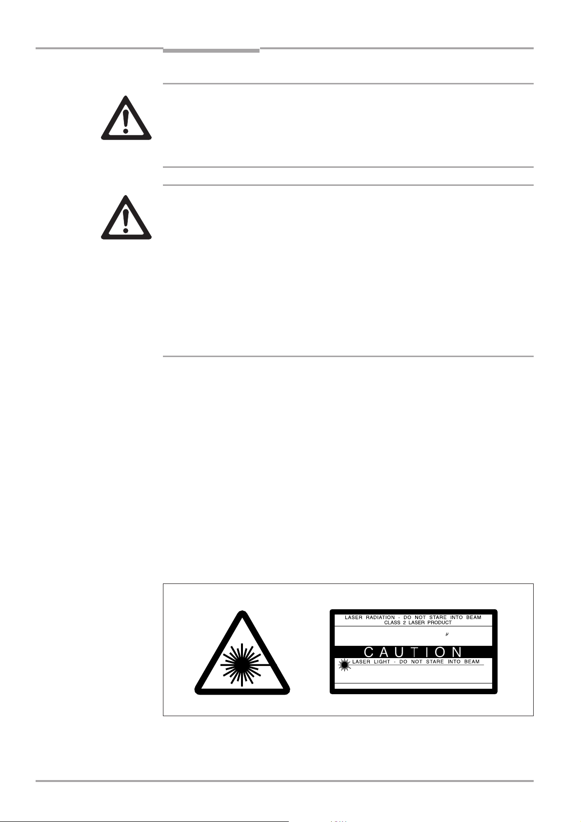
Laser beam can cause blindness!
The CLV uses a class 2 red-light laser. Looking directly at the laser beam can seriously damage your eyesight.
Ø As with sunlight, never look directly into the laser beam.
Ø Do not direct the laser beam at other persons.
Ø When mounting and aligning the CLV, avoid reflections caused by reflective surfaces.
Ø Do not open the housing.
Opening the housing does not deactivate the laser diode.
Ø Observe the most recent laser specifications (DIN EN 60825-1, latest version).
Laser power
The laser operates at a wavelength of λ =650 nm (visible red light). The power output at
the reading window is max. 2.8 mW.
The emitted radiation is not dangerous to human skin.
Laser warnings
The laser warning labels for Europe (Fig. 2-1) are attached at the following positions on
the CLV:
• The laser warning symbol on line scanners is positioned beside the reading window on
the front side of the device. The GB/US laser warning is located on the side containing
the electrical connections.
• The laser warning symbol on line scanners with oscillating mirror is located above the
reading window, on the cover of the mirror. The GB/US laser warning is located on the
side containing the electrical connections.
mW
2,8
56
650
mW
us
nm
2,8
111
650
s
nm
Fig. 2-1: Laser warning plates on the CLV
Max. output radiation:
Pulse duration:
Emitted wavelength:
EN 60825-1: 1994 + A11 : 1996
CLASS II LASER PRODUCT
Max. Output:
Pulse duration:
Wavelength:
Compiles with 21 CFR 1040.10
2-2
© SICK AG · Auto Ident · Germany · All rights reserved 8 008 796/0000/15-10-99
Page 19

Operating Instructions
CLV 490 Bar Code Scanners
Safety information
Chapter 2
Note
Explanation
The device is supplied with an additional set of laser warning labels in German/US English
and French/US English. If necessary, these can be used to cover the GB/US warnings.
If the CLV is installed in a machine/panel with the result that the laser warning
plates are no longer visible, additional warnings (not included in the scope of delivery) must be provided on the machine beside the emergence aperture of the laser
beam.
Internal protective circuits
The CLV is equipped with monitoring circuits that deactivate the laser diode in the event of
a malfunction. Activation and deactivation of the laser diode is controlled by the reading
pulse trigger.
A safety circuit (timer) automatically deactivates the laser diode in Reading mode (“Sensor
input” and “Serial interface” trigger mode) if the reading interval has not ended after 10
minutes. However, it does not end the reading interval. In this case, the CLV outputs the
message:
“Laser safety timeout”
on the terminal interface. The reading interval must be terminated by resetting the trigger
signal. The laser diode is activated again by the next reading trigger.
In the Percentage Evaluation mode, Adjusting mode and Show CP-limits as well as in
the “free-running“ reading mode the laser diode is constantly activated.
2.4 Quick stop and quick restart
2.4.1 Stopping the CLV
Ø Switch off the power supply.
This can result in loss of the following (at the most):
• the application-specific parameter set, if it was stored temporarily in the CLV
• the last reading result
• daily operating data
(operating hours counter, trigger count, good read count, maximum duration trigger,
minimum duration trigger, average identification quality)
2.4.2 Restarting the CLV
Ø Switch on the power supply.
The CLV resumes operation with the parameter set that was last stored permanently
and resets the daily operating data.
2.5 Environmental information
The CLV is designed to cause minimum impact on the environment. It does not contain
any silicone-based materials and, therefore, does not represent any problems for paint
sprayers in paint shops, for example.
© SICK AG · Auto Ident · Germany · All rights reserved8 008 796/0000/15-10-99
2-3
Page 20

Chapter 2
Safety information
Operating Instructions
CLV 490 Bar Code Scanners
2.5.1 Power requirements
The power requirements depend on the variants:
• the line scanner has a typical power consumption of 9 W and max. 16 W
• the line scanner with oscillating mirror has a typical power consumption of 9 W and max.
18 W
• the line scanner equipped with an integrated heater has a typical power consumption of
75 W and max. 90 W
• the line scanner with oscillating mirror equipped with an integrated heater has a typical
power consumption of 75 W and max. 100 W
The values are given for devices with disconnected switching outputs.
2.5.2 Disposal after removal from service
Always dispose of irreparable devices in a manner that is not harmful to the environment
and in accordance with the applicable national waste disposal regulations. The CLV can be
separated into recyclable secondary raw materials and special-category waste (electronic
scrap).
See also Section 7.3, Page 7-2.
SICK AG currently does not accept delivery of unusable or irreparable devices.
2-4
© SICK AG · Auto Ident · Germany · All rights reserved 8 008 796/0000/15-10-99
Page 21

Operating Instructions
CLV 490 Bar Code Scanners
Product description
3 Product description
3.1 Design
3.1.1 Scope of delivery
The CLV is supplied with the following in the packing:
• an information sheet (notes on device) with terminal diagram and Quick Start instruc-
tions
• an additional set of Class 2 laser warning labels (self-adhesive) in German/US English
and French/US English.
Depending on the number of devices ordered, one or more sets of technical documen-
tation comprising:
• These CLV 490 Operating Instructions in English and German
• A set of DOS-formatted disks (3.5 inch) containing the CLV-Setup program for Win-
dows™, the online help system CLV-Setup Help, and the HTML browser I-ViewPro™
Chapter 3
Section 10.11, Page 10-41, contains an overview of the available accessories, connection
modules, cables, and connectors, as well as sensors for generating the reading pulse.
3.1.2 Variants
The CLV is currently available in the following variants:
Type Part. no. Scanning method Reading window Heater
(red light)
CLV 490-0010 1 016 958 Line scanner end no
CLV 490-1010 1 016 959 Line scanner with side no
oscillating mirror
CLV 490-0011 1 016 960 Line scanner end yes
CLV 490-1011 1 016 961 Line scanner side yes
with oscillating mirror
Table 3-1: CLV variants
3.1.3 System requirements
CLV without heater
The following are required to start up and operate the CLV:
1. A SICK Connection Module from the AMV/S 60 or AMV 30 series to provide the
power supply and connect the data and function interfaces.
Available types:
- For connection one CLV:
AMV 60-011 (no. 1 017 134) for 18 ... 30 V DC,
AMS 60-013 (no. 1 017 139) for 230 V AC 50 Hz/24 V DC and
AMS 60-012 (no. 1 017 140) for 115 V AC 50/60 Hz/24 V DC
- For connecting two CLVs: AMV 30-071 (no. 1 017 391) for 18 ... 30 V DC.
© SICK AG · Auto Ident · Germany · All rights reserved8 008 796/0000/15-10-99
3-1
Page 22

Chapter 3
Product description
Operating Instructions
CLV 490 Bar Code Scanners
- or -
Alternatively, a non-SICK device with a voltage output of 18 ... 30 V DC pursuant to
IEC 742 (functional extra-low voltage) and a minimum power output of 20 W.
Cable no. 2 020 264 (3 m) with 15-pin D Sub HD connector and one open end
for connecting the CLV to the external power pack.
2. The following operating voltages/power output values:
- AMV 60-011: 18 ... 30 V DC (to IEC 742), min. 20 W
- AMV 30-071: 18 ... 30 V DC (to IEC 742), min. 40 W
- AMS 60-013: 230 V AC ±10% 50 Hz
- AMS 60-012: 115 V AC ±10% 50/60 Hz
3. With external clock pulse supply via the “Sensor” switching input: a suitable reading
pulse sensor for signaling an object with a bar code, e.g. a photoelectric reflex switch.
4. With object distance detection via the switching inputs “IN 0 ... IN 4”: suitable sensors
for multi-stage dynamic focus control, e.g. photoelectric reflex switches.
5. A PC with Windows 95™, Windows 98™, or Windows NT™ and a serial port (COM x)
6. An RS 232 data connection cable with two 9-pin D Sub sockets for connecting the PC
to the terminal interface of the CLV in the Connection Module, e.g. no. 2 014 054.
Pin 2 (RxD) and Pin 3 (TxD) are crossed
7. An HTML browser, e.g. Netscape Navitagator™, or the I-ViewPro™ browser supplied
with the device (see Section 3.1.1, Page 3-1) for using the online help system CLV-
Setup Help
8. The appropriate bus connection module BMV/BMH (available on request) for connecting the CLV to the Interbus-S, Profibus DP, or the Device Net
CLV with heater
The following are required to start up and operate the CLV:
1. A SICK Connection Module from the AMV 100 or AMV 200 series to provide the
power supply and connect the data and function interfaces.
Available types:
- For connecting one CLV: AMV 100-011 (no. 6 021 105) for 24 V DC
- For connecting two CLVs: AMV 200-011 (no. 6 021 106) for 24 V DC
- or -
Alternatively, a non-SICK power supply unit with a voltage output of
24 V DC +20%/-10% to IEC 742 (functional extra-low voltage) and a minimum
power output of 100 W.
Cable no. 2 020 264 (3 m) with 15-pin D Sub HD connector and one open end
for connecting the CLV to the external power pack.
3-2
2. The following operating voltages/power output values:
- AMV 100-011: 24 V DC +20%/-10% (pursuant to IEC 742), min. 100 W
- AMV 200-011: 24 V DC +20%/-10% (pursuant to IEC 742), min. 200 W
3. See pos. 3 under “CLV without heater”
© SICK AG · Auto Ident · Germany · All rights reserved 8 008 796/0000/15-10-99
Page 23
Operating Instructions
CLV 490 Bar Code Scanners
Product description
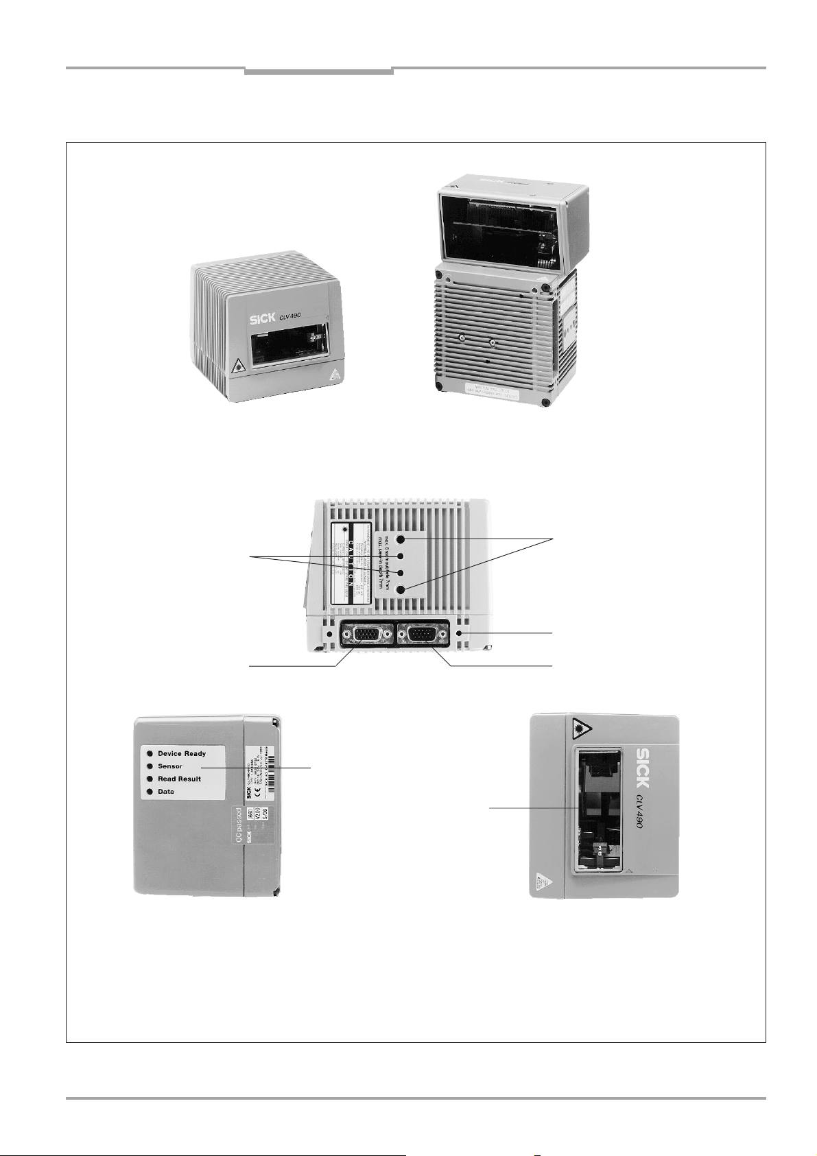
3.1.4 Layout
Chapter 3
Line scanner
(end reading window)
Line scanner with oscillating mirror
(side reading window)
Key:
Drilled hole, ∅ 3.6 mm, 6 mm
deep
Tapped blind hole M6, 7 mm
deep, for securing the device
Fig. 3-1: CLV 490
Tapped blind hole M4,
10 mm deep, for connector
cover
“Host/Term” connector
© SICK AG · Auto Ident · Germany · All rights reserved8 008 796/0000/15-10-99
“I/O” connector
LEDs
Reading window
3-3
Page 24
Chapter 3
Product description
Operating Instructions
CLV 490 Bar Code Scanners
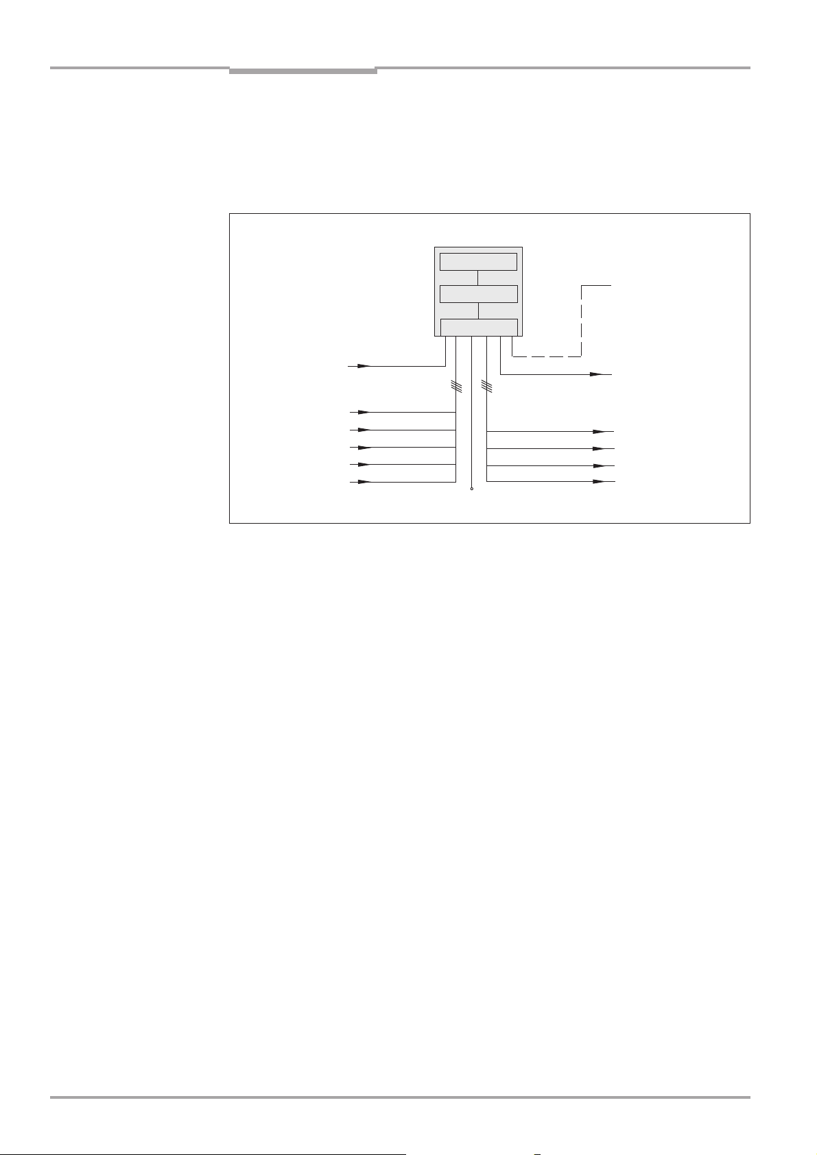
3.2 Method of operation
The CLV first scans the bar code with a scan line and then decodes it. The data is forwarded via the serial host interface to a host/PC for further processing. An overview of the
CLV functions is provided in Fig. 3-2.
CLV 490
Photoelectric
switch
Reading pulse
Signal*
Focus control
Trigger one-shot
Conveyor
increment
* if required
Fig. 3-2: Block diagram: CLV functions
“Sensor”
“IN 0”
“IN 1”
“IN 2”
“IN 3”
“IN 4”
Scanner
Decoder
Interface
V
S
“Terminal”
“Host”
“Result 1”
“Result 2”
“Result 3”
“Result 4”
Terminal
Operation
Parametrization
etc.
HOST
Further processing
of reading result
Status displays
e.g. Device Ready
e.g. Good read
e.g. No read
e.g. Match 1
The CLV is equipped with two decoders:
• The SMART decoder (SICK Modular Advanced Recognition Technology) for decoding
bar codes with small code height, bar codes that are dirty or damaged, as well as bar
codes that are tilted excessively (azimuth angle)
• The tried-and-tested standard decoder of the CLV series
The CLV derives useful diagnosis data from the reading process and transfers it to the
host. It also records operating data that can be interrogated at any time. The quality of
the read can be checked in percentage evaluation mode.
To start the reading process when an object is located in the reading field, the CLV
requires a suitable trigger. This opens a time window (“reading interval”) in the CLV. In the
default configuration, this trigger is supplied by an external reading pulse sensor. Alternative trigger sources include free-running mode or a command via the host interface (for
more complex applications: OTC triggers).
The current operating status is indicated by four LEDs.
If the trigger is supplied externally, the “Sensor” switching input instructs the CLV to start
the reading process. The five switching inputs “IN 0 ... IN 4” switch the focus position in
response to certain events, as an alternative to the autofocus function. The inputs “IN 3”
and “IN 4” can also be assigned special functions. The four switching outputs “Result 1
... Result 4” can be assigned different functions for displaying the result status and also
control external devices, such as a PLC.
The CLV is operated and configured via the terminal interface (auxiliary interface) using
the CLV Setup software or via the host interface/terminal interface using command
strings.
3-4
© SICK AG · Auto Ident · Germany · All rights reserved 8 008 796/0000/15-10-99
Page 25
Operating Instructions
CLV 490 Bar Code Scanners
Product description
Chapter 3
System, warning, and error messages help you configure the device and locate the source
of errors during startup and reading mode.
3.2.1 Autofocus function
The autofocus function enables the CLV to detect the distance of an object during the
reading process, without the need for external sensors, and then adjust the focus position
automatically to the reading plane of the bar code. In order to do so, the CLV measures
the object distance each time in its visible range in front of the reading window and
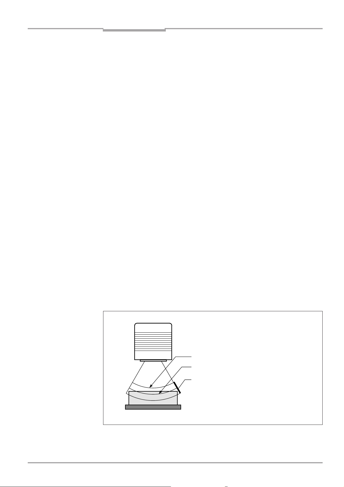
internally creates a distance profile. Following this, it positions the focus on the object.
3 operating modes are provided for various applications:
• Minimum distance: the CLV focuses on the minimum distance in the distance profile
and ignores the background in the visible range. Application: with unobstructed view of
the object without any surrounding objects protruding into the reading plane.
• Differential background: the distance profile of the visible range background is pro-
grammed (teach-in) in the CLV without any objects present. During the reading process,
the CLV then focuses on the object which it recognizes by comparing it to the distance
profile of the background. Application: with unobstructed view of the object restricted by
other objects that protrude into the reading plane.
• Differential background and tracking: if several objects with different distances are
positioned in the reading field at the same time (distance conflict), the CLV focuses on
the object that is nearest to but has not exceed its internal focus switchover point.
Application: in OTS operation (applications with tracking by the Omni Tracking Controller
OTC 400)
The distance profile of the background can also be displayed. The visible range is defined
by the autofocus range, the aperture angle, and (in the case of line scanners with oscillating mirror) also by the angle of deflection. The park setting of the focus position, from
which the device focuses for each read, can be specified in addition to a time or positionrelated delay (timeout or hysteresis). If necessary, an offset can be defined for the focus
position to be set by the measurement. The depth of field, which radiates in the direction
of the scan line and is caused by the V-principle of the beam deflection, is optimized as a
result (Fig. 3-3).
Measured distance
Optimium focus position:
measured distance plus offset for maximum
Depth of field (DOF)
Fig. 3-3: Optimizing the depth of field for the object
© SICK AG · Auto Ident · Germany · All rights reserved8 008 796/0000/15-10-99
3-5
Page 26
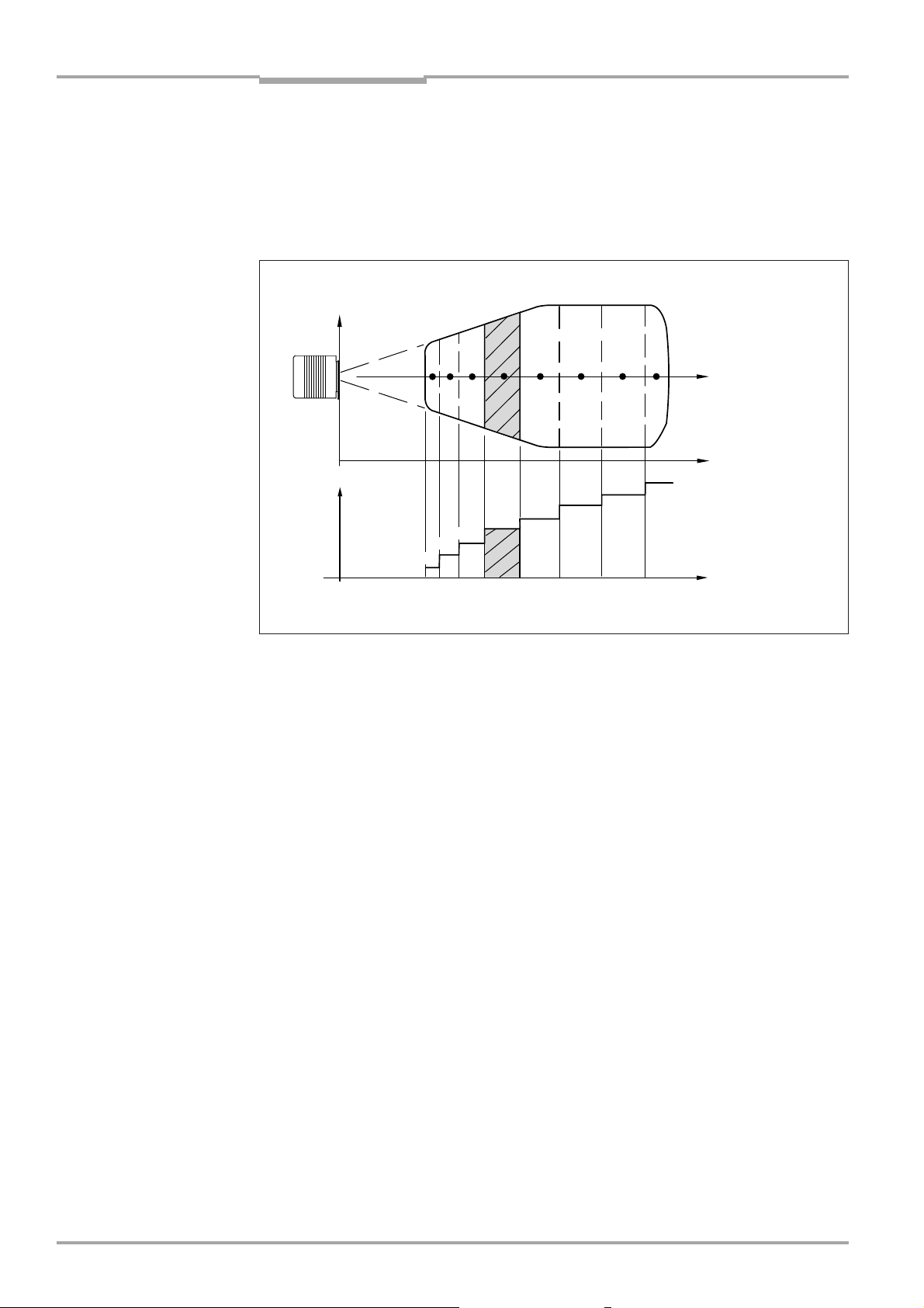
Chapter 3
Product description
Operating Instructions
CLV 490 Bar Code Scanners
3.2.2 Event-controlled dynamic focus control
As an alternative to the autofocus function, the CLV can switch its focus position in response to certain events and thus dynamically cover a large reading range. A maximum of
eight reading ranges can be defined as distance configurations for this purpose and
approached consecutively in reading mode (Fig. 3-4).
Reading
field
height
123 5 8
Focus
position
DC 2
DC 1
DC = Distance Configurations
Fig. 3-4: Dynamic focus control: classification of the reading range in distance configurations
DC 3
4
DC 4
DC 5
6 7
DC 6
DC 7
DC 8
Focus
position
Reading
distance
Reading
distance
The switchover takes place in response to changes in the object distance (with reads from
above: object height detection). The trigger source for the switchover is a signal combination at the switching inputs “IN 0 ... IN 4”, a command on the host interface or the integrated timer (e.g. for search mode). Additional in the case of the line scanner with
oscillating mirror also the oscillating mirror reversal points. The distance configurations are
assigned to the swichover sequence by means of a programmable assignment table. The
distance measurement of the autofocus function can be used to define the distance
configurations.
3-6
3.2.3 Scan procedure variants
Line scanner (standard device)
Generates a scan line; due to the V-principle of the beam generation, the reading field
height (the useful length of the scan line for evaluation purposes) is dependent on the
reading distance.
Line scanner with oscillating mirror
The oscillating mirror also deflects the scan line perpendicularly to the scan direction at
both sides around the neutral position with a low oscillating frequency. As a result, the CLV
can also scan larger areas for bar codes. Due to the V-principle of beam generation, the
reading field height is dependent on the reading distance.
In addition to parking and simple deflection with maximum amplitude, optimized oscillating
mirror functions are also available:
• Oscillating with variable deflection amplitude per distance configuration
• One-shot: one-off, defined deflection per reading pulse (forward and return phase).
© SICK AG · Auto Ident · Germany · All rights reserved 8 008 796/0000/15-10-99
Page 27

Operating Instructions
CLV 490 Bar Code Scanners
Product description
Chapter 3
3.2.4 Additional components
Heater
The CLV can be permanently equipped with a heater for applications involving temperatures up to max. -35 °C (e.g. in a freezer). The design, technical data, and power-up
behavior of the CLV are described in Section 10.4, Page 10-20.
External parameter memory
The external parameter memory is located in a connector cover which, when mounted,
covers the two electrical terminals on the CLV (IP 65). The parameter memory saves you
time when a CLV is replaced locally by providing a copy of the current parameter set. In
other words, you do not have to configure the new device.
For information on applications and operating procedures, see Section 10.3, Page 10-16.
3.3 Indicators and control elements
3.3.1 Control elements
The CLV is operated and configured via the terminal interface (auxiliary interface) using the
CLV Setup program or using command strings sent via the host interface/terminal interface. A variety of parameter options allow you to adapt the device to a wide range of
applications.
The following can be defined:
• The configuration of the code types
• The read, evaluation, and output properties
• The communication parameters of the host interface
• The structure of the data output string for “Good read” and “No read” on the host
interface
• The function of the terminal interface
Section 10.6, Page 10-23 describes the procedure for installing the CLV-Setup program
and explains how to use it. The parametrization (configuration) procedure is explained in
Section 6.4, Page 6-5.
3.3.2 Function of the LEDs
Four LEDs indicate the operating status, activity of the laser diode, reading result status,
and data transfer on the host interface. The LEDs are located on the rear of the device
(Fig. 3-5).
Fig. 3-5: LEDs
© SICK AG · Auto Ident · Germany · All rights reserved8 008 796/0000/15-10-99
Device Ready
Sensor
Read Result
Data
3-7
Page 28

Chapter 3
Product description
CLV 490 Bar Code Scanners
If the optional external parameter memory is connected, the LEDs also indicate whether
the memory was successfully accessed.
The meaning of the LEDs in the various operating modes/functions is shown in Table 3-2
and Table 3-3.
CLV without external parameter memory
Operating mode LED Display Function
Start Device Ready green • Lights up after power-up if the self-test was successful
Subsequent behavior depends on selected start option:
Start option: “S
• Lights up constantly (CLV has loaded internal parameter set)
Start option: “S
• Lights up constantly (CLV has loaded internal parameter set)
Start option: “S
• Blinks constantly together with the Read Result LED
(CLV has loaded internal parameter set)
Read Result green Start option: “S
• Blinks constantly together with the Device Ready LED
TAR T WITH EXTERNAL PARAMETERS” (default):
TAR T WITH INTER NAL PARAMETERS”:
TAR T WITH COPY INTERN -> EXTE RN”:
TAR T WITH COPY INTERN -> EXTE RN”:
Operating Instructions
1)
1)
Reading mode Device Ready green • Lights up constantly
• Extinguishes with new operating mode/function
Sensor green • Lights up if reading diode active.
(The laser diode is activated/deactivated by reading pulse)
• Lights up constantly in free-running mode, since laser diode is always
active
Read Result green LED is linked to the Result 2 switching output and indicates the selected
result status for the defined pulse duration of the output.
• Lights up after a successful read (Good Read)
• Lights up if the match code comparison is active, the bar code read
matches the specified match code(s) and the corresponding
result status output is selected for the Result 2 output
Data yellow • Blinks while the CLV transfers data to the host on the host interface
Percentage Sensor green • Lights up constantly, as free-running mode is active
evaluation Read Result green Behavior depends on the reading quality:
• Extinguishes if reading rate < 30%
• Blinks twice a second if reading rate 30% ... 70%
• Blinks five times a second if reading rate 70% ... 90%
• Lights up constantly if reading rate > 90%
Adjusting mode Sensor green • Lights up constantly, as free-running mode is active
Show CP limits Sensor green • Blinks bright/dark alternately, in the frequency with which the
scan line is (partially) masked out
1) Set the start option to “START WITH INTERNAL PARAM ETERS” on the “DEVICE CONFIGU RATION” tab in the CLV-Setup program. Download to CLV!
Table 3-2: Meaning of LEDs: CLV without external parameter memory
3-8
© SICK AG · Auto Ident · Germany · All rights reserved 8 008 796/0000/15-10-99
Page 29

Operating Instructions
Product description
CLV 490 Bar Code Scanners
CLV with external parameter memory connected
Operating mode LED Display Function
Start Device Ready green • Lights up after power-up if the self-test was successful
Subsequent behavior depends on selected start option:
Start option: “S
• Blinks for approx. 10 s before lighting up constantly.
(CLV has loaded the parameter set from the external
parameter memory and starts Reading mode straight away)
• Blinks for approx. 10 s together with the Read Result LED,
then lights up constantly.
(CLV has loaded the parameter set from the external parameter memory
with tolerated errors
• Lights up constantly.
(CLV could not find an external parameter memory and loads the internal
parameter set instead)
• Blinks constantly together with the Read Result LED
(The external parameter memory is either empty, contains the parameter
set for a different CLV type, or is corrupt.
CLV has loaded internal parameter set. It starts Reading mode
but does not output data over the host interface)
Start option: “S
• Lights up constantly (CLV has loaded internal parameter set)
Start option: “S
• Blinks alternately with the Read Result LED for approx. 10 s
before lighting up constantly.
(CLV has successfully copied the internal parameter set to the external
memory and has reset the start option to “S
CLV has loaded the internal parameter set.
• Blinks constantly together with the Read Result LED
(The external parameter memory is either not connected or corrupt, or
the parameter set is too large to be copied).
CLV has loaded the internal parameter set.
Read Result green Start option: “S
• Blinks for approx. 10 s together with Device Ready
• Blinks constantly together with the Device Ready LED
Start option: “S
• Blinks alternately with Device Ready LED for approx. 10 s (see above) or
• Blinks constantly together with the Device Ready LED2) (see above)
TAR T WITH EXTER NAL PARAMETERS” (default):
1)
and starts Reading mode straight away)
TAR T W ITH INTERNAL PARAMETERS”:
TAR T WITH COPY INTER N -> EXTER N”:
TA RT WITH EXTERNAL PARAMETERS”).
TAR T WITH EXTERNAL PARAMETERS” (Default):
TAR T WITH COPY INTER N -> EXTER N”:
Chapter 3
2)
.
2)
1)
LED (see above) or
2)
(see above)
Reading mode Device Ready green • Lights up constantly
• Extinguishes with new operating mode/function
Sensor green • Lights up if reading diode active.
(The laser diode is activated/deactivated by the reading pulse)
• Lights up constantly in free-running mode, since the laser diode is
constantly active
Read Result green LED is linked to the Result 2 output and indicates the selected result
status for the defined pulse duration of the output.
• Lights up after a successful read (Good Read)
1) We recommend that you check the parameter set manually, e.g. by printing out the entire configuration. For troubleshooting, see also Section 8.3.2, Page 8-5
2) Stops blinking when you switch from Reading mode to Parameter mode
Table 3-3: Meaning of LEDs: CLV with external parameter memory
© SICK AG · Auto Ident · Germany · All rights reserved8 008 796/0000/15-10-99
3-9
Page 30

Chapter 3
Operating mode LED Display Function
Reading mode Read Result green • Lights up if the match code comparison is active, the bar code read
(contd.) (contd.) matches the specified match code(s) and the corresponding result
Data yellow • Blinks while the CLV transmits data to the host over the host interface
Percentage Sensor green • Lights up constantly, since free-running mode is active
evaluation Read Result green Behavior dependent on the reading quality:
Adjusting mode Sensor green • Lights up constantly, since free-running mode is active
Show CP limits Sensor green • Blinks bright/dark alternately, in the frequency with which the
Table 3-3: Meaning of LEDs: CLV with external parameter memory (continued)
Product description
output is selected for the Result 2 output
• Extinguishes if reading rate < 30%
• Blinks twice a second if reading rate 30% ... 70%
• Blinks five times a second if reading rate 70% ... 90%
• Lights up constantly if reading rate > 90%
scan line is (partially) masked out
Operating Instructions
CLV 490 Bar Code Scanners
3-10
© SICK AG · Auto Ident · Germany · All rights reserved 8 008 796/0000/15-10-99
Page 31

Operating Instructions
CLV 490 Bar Code Scanners
4 Installation
Installation
4.1 Installation sequence
• Change the language version of the laser warning label (if necessary)
• Select the mounting location for the CLV
• Align the CLV with the bar code
• Mount the CLV
• Mount the AMV/S 60 Connection Module
• Connect the CLV to the AMV/S 60 Connection Module
• Adjust the CLV so that it is in line with the bar code
• Mount the reading pulse sensor for external triggering the reading pulse
• Option with event-controlled dynamic focus control:
mount the sensors for detecting the object distance
4.2 Preparations
Chapter 4
4.2.1 Required components
• CLV bar code scanner
4.2.2 Required accessories
• SICK mounting bracket for the CLV:
depending on the order, angle bracket no. 2 013 824, articulated bracket no. 2 021
147, or quick-clamping device no. 2 016 110 with securing material for the CLV
- or -
Alternatively, if the bracket is supplied by the user
- Stable mounting device that allows the alignment of the CLV to be varied in the x and y
axes. The weight of the CLV (line scanner) is 1.5 kg and 2.2 kg as a line scanner with
oscillating mirror
- 2 screws M6 for the CLV. The screw length depends on the wall thickness of the
bracket used. Depth of engagement in CLV max. 7 mm from housing surface
• AMV/S 60 Connection Module (not included in the scope of supply of the CLV)
• Reading pulse sensor for external reading pulse trigger, e.g. photoelectric reflex switch/
photoelectric proximity switch (not included in the scope of supply of the CLV)
• Option with event-controlled dynamic focus control: sensors for detecting the object
distance, e.g. photoelectric reflex switches/photoelectric proximity switches (not
included in the scope of supply of the CLV)
4.2.3 Required auxiliary parts
• 2 screws M6 for securing the SICK mounting bracket to the base. The screw length
depends on the wall thickness of the base.
• Set of laser warning labels (if necessary)
• Tool
• Measuring tape (up to 3,000 mm)
• Protractor
© SICK AG · Auto Ident · Germany · All rights reserved8 008 796/0000/15-10-99
4-1
Page 32

Chapter 4
Installation
Operating Instructions
CLV 490 Bar Code Scanners
4.2.4 Replacing the laser warning label
If necessary, replace the GB/US laser warning label with the required language (Fig. 4-1).
The device is delivered with a set of laser warnings in:
• German/US laser warning and
• French/US laser warning
See also Section 2.3, Page 2-2.
Laser warnings:
Fig. 4-1: Line scanner: replacing the laser warning labels
4.2.5 Selecting the mounting location
When you select the mounting location, the distance between the CLV and the host and
between the CLV and the bar code are extremely important.
Distance between the CLV and the host
The CLV can be mounted at a maximum distance of 1200 m from the host without a
connection to the SICK network or a bus. In practice, however, the distance depends on
the physical configuration of the host interface and the data transfer rate.
See Table 5-7, Page 5-8.
Distance between the host and the AMV/S 60 Connection Module
The AMV/S 60 Connection Module should not be located further than 10 m from the CLV,
since the CLV Setup program on the PC accesses the terminal interface of the CLV via this
module (RS 232).
4.2.6 Mounting accessories
The CLV is secured in position using the two tapped blind holes (M6) above the electrial
connections. The position of these holes is shown in Fig. 4-2.
The dimensions of the CLV housing are shown in Figs. 9-1 to 9-3, Page 9-3 onwards.
4-2
© SICK AG · Auto Ident · Germany · All rights reserved 8 008 796/0000/15-10-99
Page 33

Operating Instructions
CLV 490 Bar Code Scanners
Installation
Chapter 4
Pin holes,
∅ 3.6, 6 mm deep
CLASS II LASER PRODUCT
Max. Output:
Pulse duration:
Wavelength:
Compiles with 21 CFR 1040.10
2,8
56
650
mWusnm
Emitted wavelength:
EN 60825-1: 1994 + A11 : 1996
650
Max. output radiation:
Pulse duration:
2,8
111
mWusnm
Tapped blind hole,
M6, 7 mm deep
101010
38.5
33.4
78
43.3
56
12
21
Fig. 4-2: Line scanner: position of the securing threads on the CLV
The CLV can be mounted using the SICK bracket:
• mounting bracket, single no. 2 013 824
• articulated bracket (2 x mounting bracket, douple) no. 2 018 435
• quick-clamping device no. 2 016 110
The brackets are designed to support a variety of mounting positions and alignments in
two planes. Fig. 4-3 shows two mounting examples.
The elongated holes in the mounting bracket no. 2 013 824 and in the articulated bracket
no. 2 018 435 allow the CLV to be adjusted with a freedom of rotation of ±15°.
quick-clamping
device
mounting
bracket
Fig. 4-3: CLV mounting options using the mounting bracket no. 2 013 824 in combination with
the quick-clamping device no. 2 016 110
The dimensions of the mounting brackets are shown in Section 10.12, Page 10-45.
© SICK AG · Auto Ident · Germany · All rights reserved8 008 796/0000/15-10-99
4-3
Page 34

Chapter 4
Installation
Operating Instructions
CLV 490 Bar Code Scanners
4.2.7 Distance between the CLV and the bar code
Basic alignment between the CLV and bar code
Depending on the application, the line scanner or line scanner with oscillating mirror
versions of the CLV is used. Fig. 4-4 shows how the device is aligned with the bar code on
the object for each of the two scanning methods.
Line scanner
Fig. 4-4: Scanning methods: alignment with bar code and conveyor direction
Line scanner with
oscillating mirror
Reading distance from the bar code and aperture angle α
The distance between the reading window of the CLV and the bar code must not exceed
the technical limits. The height of the reading field is shown as a function of the reading
distance for various resolutions (module widths) in Sections 10.2.3, Page 10-3 and in
Section 10.2.4, Page 10-9.
Fig. 4-5 shows the definition of the reading distance a from the reading window and of the
aperture angle α for each of the two scanning methods.
Line scanner
α
Reading distance a
Fig. 4-5: Definition of the reading distance a and the aperture angle α
Line scanner with
oscillating mirror
α
Reading distance a
105°
The useful aperture angle α is max. 56° for the line scanner and max. 50° for the line
scanner with oscillating mirror. Due to the V-principle of beam deflection, the reading field
height (for evaluating the useful length of the scan line) depends on the reading distance.
4-4
© SICK AG · Auto Ident · Germany · All rights reserved 8 008 796/0000/15-10-99
Page 35

Operating Instructions
CLV 490 Bar Code Scanners
Installation
Chapter 4
Angular alignment of the CLV
The alignment of the CLV is optimum when the scan line travels over the bar code lines
almost at a right angle (90°) (Fig. 4-4). All possible reading angles that can occur between
the scan line and the bar code must be taken into consideration (Fig. 4-6 and Table 4-1).
Reading
range
Reading
CLV
Fig. 4-6: Line scanner: reading angles between the scan line and the bar code
Angle Limit value
Tilt α (azimuth) max. 45°
Pitch β max. 45°
Skew γ max. 45°
Table 4-1: Permissible reading angles between the scan lines and bar code
distance
α: Tilt (azimuth angle)
β: Pitch
γ: Skew
Avoiding surface reflection
If the light from the scan line strikes the surface of the bar code vertically, interference may
be caused by reflections when the returned light is received. To avoid surface reflection,
the CLV must be mounted in such a way that the emitted light is tilted slightly with respect
to the vertical axis (Fig. 4-7).
Line scanner
15°
(Top view)
Fig. 4-7: Avoiding surface reflection: angle between the emitted light and bar code (tilted away
from the vertical axis)
Line scanner with oscillating mirror
15°
105°
(Side view)
In the case of the line scanner with oscillating mirror, the laser beam is emitted at an angle
of 105° with respect to the housing as it passes through the neutral position (CW=50)
while oscillating. The device can only be flush-mounted with the conveyor belt with limited
© SICK AG · Auto Ident · Germany · All rights reserved8 008 796/0000/15-10-99
4-5
Page 36

Chapter 4
Installation
Operating Instructions
CLV 490 Bar Code Scanners
deflection ranges. Otherwise, the device must also be mounted at an angle of 15° to
ensure that the deflection ranges are symmetric.
Note
Explanation
In oscillating mode with variable amplitude, the scan line must always sweep the neutral
position (CW=50). This means that oscillation is not possible in the range 60 CW to 80
CW, for example, but is possible in the range 40 CW to 80 CW.
4.2.8 Count direction of the code position CP and code angle CW
The CLV can scan and decode several bar codes with each read.
In doing so, it determines the specific local reading diagnosis data for each bar code:
• the position (CP value) of the center of the bar code within the scan line
• (scanning method using the oscillating mirror) also the angle of deflection of the scan
line (CW value) at which the center of the bar code is recorded
Fig. 4-8 shows the count direction of the code position and code angle. In the case of the
line scanner, the count direction of the code position is marked by a small triangle above
the reading window.
By determining this data, the device can separate identical bar codes (code type, code
length, and data content identical) and assign the bar code data in the reading result to its
position on the object.
Line scanner
Line scanner with
oscillating mirror
90
100
CP
0
CP
Marking:
count direction
of the code
position
Angle of deflection α (aperture angle) in scan direction: 1°= 1,5 CP (56°= 90 CP)
Angle of deflection of the scan line perpendicular to the scan direction: 1°= 2 CW (20° = 40 CW)
Fig. 4-8: Count direction of the code position CP in the scan line and of the code angle CW for
the oscillating mirror
In the default setting, the CLV does not output the “CP” and “CW” values (line scanner with
TIP
100
oscillating mirror only) in the reading result on the host interface. If this is required to
evaluate the result in the host, the values can be included in the separator of the output
string using the CLV Setup program.
CW
10
0
4-6
Configuring the separator:
1. Choose the “DATA STRINGS” tab.
2. Click the “SEPARATOR” field.
The “EDIT PARAMETER TFS” dialog box is displayed.
© SICK AG · Auto Ident · Germany · All rights reserved 8 008 796/0000/15-10-99
Page 37

Operating Instructions
CLV 490 Bar Code Scanners
Installation
3. In the list field, click the CP and/or CW parameters in the required order.
CP and/or CW then appears in the top line.
4. Confirm your selections with OK.
5. Download the data to the CLV by clicking in the toolbar.
The “DOWNLOAD PARAMETERS” dialog box is then displayed.
6. Confirm the dialog box by choosing “PERMANENT”.
The CLV outputs the CP value and the CW value on the host interface for each bar
code in the reading result. The values are displayed as a 3-digit number in the associated separator.
Chapter 4
4.3 Mounting and adjusting the device
4.3.1 Mounting the CLV
1. Prepare the base for mounting the bracket as described in Section 4.2.2, Page 4-1.
2. Place the object containing the bar code within the visible range of the CLV (in the
position at which it is to be read) with the conveyor belt switched off.
IM PORTANT
3. Align the CLV with the bar code (in accordance with the scanning method) in such a
way that
- with the line scanner the back of the device with the LEDs is almost parallel with the
bar code surface
- with the line scanner with oscillating mirror, the broad side wall (back of the oscillating
mirror) is almost parallel with the bar code surface
All of the possible reading angles must be taken into consideration (see Fig. 4-6,
Page 4-5).
4. If it is relevant for the evaluation, note the count direction of the code position and
code angle (see Fig. 4-8, Page 4-6).
5. Mount the CLV bracket on the base.
Risk of damage to the housing!
The maximum depth of engagement of the two tapped blind holes M6 is 7 mm.
Longer screws will damage the housing.
Ø Use screws with the correct length.
6. Screw the screws M6 through the bracket into the tapped blind holes of the CLV.
7. Tighten the screws slightly.
8. Adjust the CLV as described below.
© SICK AG · Auto Ident · Germany · All rights reserved8 008 796/0000/15-10-99
4-7
Page 38

Chapter 4
Installation
Operating Instructions
CLV 490 Bar Code Scanners
4.3.2 Adjusting the CLV
The CLV can be adjusted in Percentage Evaluation mode. In this mode, the CLV displays
the quality of the bar code reads that enter the CLV reading field statically (the object is
not moved on the conveyor belt). The CLV performs 100 scans and evaluates the reading
quality statistically. It then outputs the reading results every 2 s on the terminal interface.
The behavior of the “Read result” LED also indicates the reading quality. The LED does not
light up if the CLV cannot read the bar code (reading quality <30%). If the CLV is having
problems reading the bar code (reading quality 30% ... 90%), the LED blinks. The CLV is
aligned optimally when the LED lights up constantly (reading quality >90%). The scanning
frequency in the default setting is 800 Hz.
1. Connect the CLV to the AMV/S 60 Connection Module and switch on the power supply
(see Section 5.5.3, Page 5-13).
After it has started, the CLV confirms that the self-test was successfuly and switches
to Reading mode (Device Ready LED lights up).
2. Connect the PC to the terminal interface of CLV via the RS 232 line using the internal
9-pin “Service” connector of the AMV/S 60 (see Section 5.5.5, Page 5-15).
3. Start Windows and the CLV Setup program
(see Section 10.6.3, Page 10-25).
Choosing the standard decoder:
4. Choose the “CODE CONFIGURATION” tab.
5. Click the “STA N D AR D ” option in the “DECODER” group.
6. Download the settings to the CLV by clicking on the toolbar.
The “DOWNLOAD PARAMETERS” dialog box is then displayed.
7. Confirm the dialog box by choosing “TEMPORARY”.
The CLV then operates with the standard decoder.
Activating Percentage Evaluation mode:
8. From the “VIEW” menu, choose “PERCENTAGE EVALUATION”.
The dialog box for entering the distance configuration appears.
9. Click the relevant distance configuration for the reading distance:
- with auto-focus mode the distance configuration no. 1
- with event-controlled dynamic focus control the distance configuration that matches
the reading distance of the object (default: no. 1, focus position F = 1,200 mm).
10. Confirm the dialog box with OK.
The Terminal Emulator is launched and displays the reading result continuously
(see Section 6.5.2, Page 6-22).
Monitor the reading quality (%) during each of the subsequent steps!
Line scanner with oscillating mirror:
In Percentage Evaluation mode, the CLV switches of oscillating mode (default setting:
oscillating) and positions the scan line at the angle 50 CW, corresponds to an angle of
emergence of 105°. The angle can not be changed.
4-8
Fine adjustment:
11. Align the CLV in such a way that the angle between the scan line and the bars on the
bar code CLV is almost 90°. The oscillating mirror must be aligned in such a way that
the scan line is located at the center of the bar code, perpendicular to the bar code
lines, when it is in the neutral position (CW=50).
© SICK AG · Auto Ident · Germany · All rights reserved 8 008 796/0000/15-10-99
Page 39

Operating Instructions
CLV 490 Bar Code Scanners
Installation
Chapter 4
12. To avoid interfering reflections, tilt the CLV away from the vertical axis so that the light
strikes the bar code at an angle of approx. 105° (line scanner) (see Fig. 4-7, Page 4-5).
13. If necessary, position the scan line exactly at the direct center of the bar code.
See Section 4.3.3 below.
14. Move objects carrying bar codes into the CLV reading field manually under realistic
conditions and check the reading result. If the objects aligned randomly, or if the bar
code is located at different positions (angles), ensure that the limit values of the
permissible reading angles are not exceeded.
15. Adjust the CLV in such a way that the good read rate is between 70...100%.
With event-controlled dynamic focus control, for each defined reading range (distance
configuration), check the selected focus position and correct the parameter settings if
necessary (see Section 6.4.3, Page 6-9).
16. Tighten the screws on the CLV.
The CLV is aligned with the bar code.
4.3.3 Adjusting mode
The “Adjusting mode” helps you to position the center of the scan line on the object. To do
so, the CLV masks out one half of the scan line from the center (code position CP=50 to
CP=100). This is irrespective of whether the CLV is operated in Autofocus mode or with
distance configurations for event-driven dynamic focus control.
Fig. 4-9 shows the resulting position of the scan line (line scanner).
“Adjusting mode”
Scan line
CP = 100
CP = 50
CP = 0
Abb. 4-9: Line scanner: scan line in “Adjusting mode“
Range
masked
out
Line scanner with oscillating mirror:
In Adjusting mode, the CLV switches of oscillating mode (default setting: oscillating) and
positions the scan line at the angle 50 CW, corresponds to an angle of emergence of
105°. The angle can not be changed.
1. Activate the operating mode as described in Section 6.5.3, Page 6-23.
2. Position the CLV in such a way that the center of the scan line, indicated by the end of
the scan line (code position CP=50), is located at the center of the bar code, or at the
center of the field for all codes if several bar codes are used.
© SICK AG · Auto Ident · Germany · All rights reserved8 008 796/0000/15-10-99
4-9
Page 40

Chapter 4
Installation
Operating Instructions
CLV 490 Bar Code Scanners
4.4 Mounting the external components
4.4.1 Mounting the AMV/S 60 Connection Module
1. Mount the AMV/S 60 Connection Module near the CLV.
The distance between the AMV/S 60 and CLV should not exceed max. 10 m.
2. Mount the AMV/S 60 in such a way that the device can be accesses when opened.
The terminal interface of the CLV is accessed via the internal “Service” connector.
Detailed information on the mounting and electrical installation procedures is provided in
the Operating Instructions for the “AMV/S 60 Connection Module” (order no. 8 008 296).
4.4.2 Mounting the external reading pulse sensor
If the CLV is triggered by an external reading pulse sensor, the sensor must be mounted in
the vicinity of the CLV. The “Sensor” switching input is selected as the default trigger
source for this trigger type. The default debounce time of the input is 30 ms.
Fig. 4-10 shows two examples of where a photoelectric reflex switch can be mounted.
This depends on the distance a from the bar code to the front of the object. Depending on
the application, you may need to mount the sensor in such a way that bar codes on
objects of different sizes can be read completely during the reading interval.
Bar code in the center or at the end of the object
a
b
Bar code at the start of the object
a
b
Fig. 4-10: Line scanner: mounting example for the external reading pulse sensor
b < a !
b < a !
b < a
b < a
(Top view)
a
b
(Top view)
a
b
4-10
© SICK AG · Auto Ident · Germany · All rights reserved 8 008 796/0000/15-10-99
Page 41

Operating Instructions
CLV 490 Bar Code Scanners
Installation
Chapter 4
1. Mount the reading pulse sensor.
2. Connect the reading pulse sensor to the “Sensor” switching input of the CLV via the
AMV/S 60 Connection Module (see Section 5.5.6, Page 5-16).
3. Connect the CLV to the AMV/S 60 Connection Module and switch on the power supply
to the module (see Section 5.5.3, Page 5-13).
After it has started, the CLV confirms that the self-test was successfuly and switches
to Reading mode (Device Ready LED lights up).
4. Connect the PC to the terminal interface of CLV via the RS 232 line using the internal
9-pin “Service” connector of the AMV/S 60 (see Section 5.5.5, Page 5-15).
5. Start Windows and the CLV Setup program
(see Section 10.6.3, Page 10-25).
6. From the “VIEW” menu, choose “READING MODE”.
The Terminal Emulator is launched. The CLV is in Reading mode (default: SMART
decoder).
Monitor the reading result during each of the subsequent steps!
Line scanner with oscillating mirror:
In Reading mode, the CLV deflects the scan line (default setting) about the fixed
position CW=50 with a frequency of 1 Hz at a max. angle of ±20° (±40 CW).
50 CW corresponds to an angle of emergence of 105°.
7. Move objects with bar codes into the CLV reading field manually under realistic conditions and check whether the reading result and trigger pulse are correct.
8. Repeat the procedure with the conveyor switched on. Check whether the reading
procedure is synchronized with the objects.
Parameterizing an external sensor as a trigger source:
These settings are not required if the CLV is operated with the default configuration.
1. Choose the “DEVICE CONFIGURATION” tab.
2. Click the “EDIT READING TRIGGER” button.
The “EDIT READING TRIGGER” dialog box is displayed.
3. Choose “SENSOR INPUT (ACTIV E HIGH)” and confirm your selection.
4. Download the settings to the CLV by clicking in the toolbar.
The “DOWNLOAD PARAMETERS” dialog box is then displayed
5. Confirm the dialog box by choosing “PERMANENT”.
The CLV operates with the “Sensor” switching input as an external trigger source. The
reading pulse starts when the power supply is connected.
© SICK AG · Auto Ident · Germany · All rights reserved8 008 796/0000/15-10-99
4-11
Page 42

Chapter 4
Installation
Operating Instructions
CLV 490 Bar Code Scanners
4.4.3 Mounting the sensors for detecting the object distance
If the dynamic focus control function of the CLV is triggered by external sensors, suitable
sensors must be mounted in the vicinity of the CLV. Fig. 4-11 shows an example of a read
operation from above. The sensors must be arranged in such a way that all of the
potential object heights are classified uniquely and overlapping reading ranges occur that
can be formed with the depths of field of the CLV. A maximum of five switching inputs are
available for this purpose. A max. of 32 switching states for 8 distance configurations
(reading ranges) can be implemented using the internal assignment table (combinations).
Photoelectric reflex switches, for example, can be used to detect the object distance. In the
default setting, all five switching inputs IN 0 ... IN 4 are selected for dynamic focus control.
Object distance
DC 8
AK8
h7
LS7
Reading
distance
Fig. 4-11: Mounting example for object distance detection
DC 2
AK2
DC 1
AK1
Object
DC = Distance configuration
LS2
h2
h1
LS1
1. The depths of field of the CLV for the bar code resolution in question is shown in the
graphs in Fig. 10-2 up to Fig. 10-6 (line scanner) or in Fig. 10-8 up to Fig. 10-12 (line
scanner with oscillating mirror) in Section 10.2, Page 10-2 onwards. Find and note
suitable focus positions for overlapping reading ranges.
2. Mount distance sensors (e.g. photoelectric reflex switches) one above the other in a
row at the mounting location to measure the object distance (see also assignment
table 5-20, Page 5-18). It is advisable to mount these distance sensors opposite the
direction of motion of the conveyor belt at approx. 100 mm in front of the reading
pulse sensor.
4-12
3. Connect the distance sensors to the “IN 0 ... IN 4” switching inputs on the CLV via the
AMV/S 60 Connection Module (see Section 5.5.7, Page 5-16).
4. Set the focus positions for the required reading ranges on the “READING CONFIGURATION”
tab in the CLV Setup program.
To do so, click the “DISTANCE CONFIGURATION /ASSIGNMENT TABLE” button and edit the
required entries in the dialog box that is then displayed.
© SICK AG · Auto Ident · Germany · All rights reserved 8 008 796/0000/15-10-99
Page 43

Operating Instructions
CLV 490 Bar Code Scanners
Note
Installation
5. As described in Section 4.3.2, Page 4-8, choose the standard decoder and start
Percentage Evaluation mode temporarily.
6. Check the reading quality in all distance configurations while the conveyor belt is
stationary.
7. Then check the distance detection function in Reading mode under realistic conditions.
To do so, monitor the reading result in the Terminal Emulator as described in Section
4.4.2, Page 4-11.
Default: Focus position F 1 up to F 8 = 1,200 mm
The CLV can switch between a maximum of 8 distance ranges for slow search runs using
the integrated timer or the oscillating mirror reversal points.
The CLV can be switched between a maximum of 8 distance ranges synchronously to the
reading process using command strings.
Chapter 4
4.5 Dismantling the device
1. Switch off the power supply to the AMV/S 60 Connection Module.
2. Undo the screws for the cable connections on the CLV and disconnect the cables.
With mounted external parameter memory (optional):
Undo both screws and remove the cover.
3. Unscrew the CLV from the mounting device.
When removing the device from service for the last time, please dispose of it in an environmentally-friendly manner, as described in Section 7.3, Page 7-2.
© SICK AG · Auto Ident · Germany · All rights reserved8 008 796/0000/15-10-99
4-13
Page 44

Chapter 4
Installation
(blank page)
Operating Instructions
CLV 490 Bar Code Scanners
4-14
© SICK AG · Auto Ident · Germany · All rights reserved 8 008 796/0000/15-10-99
Page 45

Operating Instructions
CLV 490 Bar Code Scanners
Electrical installation
5 Electrical installation
5.1 Installation sequence
• Connect the CLV to a SICK Connection Module from the series AMV/S, BMV/BMH
or BMS, or using a customer-specific wiring configuration
• Connect the data and function interfaces of the CLV in the module
• Connect the PC to the Connection Module (at the terminal port on the CLV)
• Connect the power supply to the Connection Module
5.1.1 SICK Connection Module (overview)
CLV Type Temperature Connection Purpose see
range module section
CLV without heater 0 ... +40 °C AMV 60 - Connecting one CLV 5.2.3
- Operating voltage 18 ... 30 V DC
- Degree of protection IP 30, max. IP 54
Chapter 5
AMS 60 - Connecting one CLV 5.2.3
- Operating voltage 230 V AC (115 V)/24 V DC
- Degree of protection IP 30, max. IP 54
AMV 100 - Connecting one CLV 5.2.3
- Operating voltage 18 ... 30 V DC
- Degree of protection IP 52,
with connector cover max. IP 65
BMV/BMH 10 - Connecting one CLV to the Profibus-DP 5.2.4
Profibus-DP - Operating voltage 20 ... 30 V DC
- Degree of protection IP 52,
with connector cover max. IP 65
BMS 20 - Connecting one CLV to the Interbus-S 5.2.4
Interbus-S - Operating voltage 24 V DC
- Degree of protection max. IP 54
AMV 30-071 - Connecting two CLVs 5.2.3
- Operating voltage 18 ... 30 V DC
- Degree of protection IP 30, max. IP 54
AMV 200 - Connecting two CLVs 5.2.3
- Operating voltage 18 ... 30 V DC
- Degree of protection IP 52,
with connector cover max. IP 65
CLV with heater AMV 100 - Connecting one CLV 5.2.3
- Line scanner –35 ... +35 °C - Operating voltage 24 V DC +20%/–10%
- Line scanner –25 ... +35 °C - Degree of protection IP 52,
with oscillating mirror with connector cover max. IP 65
Table 5-1: Connection Modules for the CLV
© SICK AG · Auto Ident · Germany · All rights reserved8 008 796/0000/15-10-99
AMV 200 - Connecting two CLVs 5.2.3
- Operating voltage 24 V DC +20%/–10%
- Degree of protection IP 52,
with connector cover max. IP 65
5-1
Page 46

Chapter 5
Electrical installation
Operating Instructions
CLV 490 Bar Code Scanners
5.2 Electrical connections and cables
The electrical connections on the CLV consist of two 15-pin D Sub HD connections on the
housing, one connector, and one socket.
These connections are used to route the following interfaces:
• two serial data interfaces (host interface and terminal interface)
• six switching inputs (external reading pulse and multifunctional inputs)
• four switching outputs (for result status function, for connecting to a PLC for example)
• CAN bus (for OTS operation)
• power supply
5.2.1 Wire cross-sections
CLV without heater:
Ø All of the connections must be wired with copper cables with a minimum wire diameter
of 0.15 mm2!
CLV with heater:
Ø Connect the power supply terminals (Pin 1/Pin 5) using copper wires with a minimum
cross-section of 0.75 mm2 at a maximum length of 10 m!
5.2.2 Prefabricated cables (overview)
CLV Type Temperature Connection Optional Length Type
range module cables
CLV without heater 0... +40 °C AMV/S 60 2 x No. 2 020 302 or 3 m Connection cable
1 x No. 2 020 307 or 3 m Ext. parameter memory with cables
BMV/BMH 10 1 x No. 2 020 307 or 3 m Ext. parameter memory with cables
Profibus-DP 1 x No. 2 021 298 3 m Connector cover IP 65 with cables
AMV 30-071 2 x No. 2 020 302 or 3 m Connection cable
1 x No. 2 020 307 3 m Ext. parameter memory with cables
BMS 20 1 x No. 2 020 264 + 3 m Connection cable w. open end
Interbus-S 1 x No. 2 020 265 or 3 m Connection cable
1 x No. 2 020 308 3 m Ext. parameter memory with cables
Ext. power 1 x No. 2 020 303 + 3 m Connection cable w. open end
pack 1 x No. 2 020 264 or 3 m Connection cable w. open end
1 x No. 2 020 981 or 3 m Ext. parameter memory with cables
1 x No. 2 021 267 3 m Connector cover IP 65 with cables
CLV with heater –35 ... +35 °C AMV 100 1 x No. 2 021 298 3 m Connector cover IP 65 with cables
Table 5-2: Cables for connecting the CLV
For technical data on the cables, see Section 10.11.3, Page 10-43.
5-2
© SICK AG · Auto Ident · Germany · All rights reserved 8 008 796/0000/15-10-99
AMV 200 2 x No. 2 021 298 3 m Connector cover IP 65 with cables
Ext. power 1 x No. 2 021 267 3 m Connector cover IP 65 with cables
pack
Page 47

Operating Instructions
CLV 490 Bar Code Scanners
Electrical installation
Chapter 5
5.2.3 Connections/cables for the AMV/S Connection Module
The AMV/S Connection Module is suitable for connecting the CLV to peripherals (distribution function) and the power supply. The module can be used to establish a connection to
the host (point-to-point) or integrate the device in a SICK network or daisy-chain configuration (pass-through or master/slave configuration).
The module is available in several variants (see Table 5-1).
Fig. 5-1 shows the connection principle of the AMV/S 60 for one CLV.
CLV 490
Scanner
Decoder
Photoelectric
switch
Reading pulse
Photoelectric
switches
Focus control
Trigger one-shot
Conveyor increment
Connecting cable (if necessary)
Fig. 5-1: Block diagram: connecting the CLV to the AMV/S 60 Connection Module
Interface
Terminal
Host
Result 1 ... 4
Sensor
IN 0 ... 4
18 ... 30 V DC
Sensor
IN 0 ... 4
AMV/AMS 60
Connection Module
Connecting the CLV to the AMV/S
Two cables no. 2 020 302 are required to connect the CLV to the AMV/S.
Alternatively, the device can be connected via the external parameter memory
no. 2 020 307 (see Section 5.2.5, Page 5-5).
. . . . .
Terminal
. . . .
Terminal
Host
Result 1 ... 4
18 ... 30 V DC (AMV 60-011)
230 V AC (AMS 60-013)
115 V AC (AMS 60-012)
HOST/PLC
PLC
Recommendation
a) CLV without heater:
Connection modules: AMV/S 60 and AMV 30-071.
The cables no. 2 020 302 can be extended to 10 m (terminal interface: RS 232!).
b) CLV with heater:
Connection modules: AMV 100 and AMV 200.
The cables no. 2 020 302 must not be extended!
If longer cables are required, the entire power supply system (Pin 1/Pin 5) must be
connected with a wire cross-section of at least 0.75 mm2 with a maximum length of 10 m.
Use the cable no. 2 021 298 (with two connector covers, length 3 m).
© SICK AG · Auto Ident · Germany · All rights reserved8 008 796/0000/15-10-99
5-3
Page 48

Chapter 5
Electrical installation
Operating Instructions
CLV 490 Bar Code Scanners
The procedures for connecting and configuring the AMV/S Connection Modules are
described in the following documentation:
• Operating Instructions for the AMV/S 60 Connection Module (no. 8 008 296)
• Operating Instructions for the AMV 30-071 Connection Module (no. 8 008 xxx)
• Operating Instructions for the AMV 100/200 Connection Module (no. 8 008 879)
5.2.4 Connections/cables for the Bus Connection Modules
BMV 10 and BMS 20
The BMV 10 Bus Connection Module is used to connect a CLV to the Profibus-DP for use
in industrial applications and also enables the CLV to be integrated in the Interbus-S.
Connecting the CLV to the BMV 10/BMS 20
BMV 10: two cables no. 2 020 302 are required.
BMS 20: the cables no. 2 020 265 and no. 2 020 264 are required.
Alternatively, via external parameter memory no. 2 020 307 (see Section 5.2.5,
Page 5-5).
Recommendation
a) CLV without heater:
Connection modules: BMV 10 and BMS 20.
The cables no. 2 020 302 can be extended to 10 m for CLVs without
a heater (host and terminal interface: RS-232!).
b) CLV with heater:
Connection module: BMV 10.
The BMV 10 may only be used if it is mounted outside the refrigeration area (temperature
range 0 ... +40 °C).
The cables no. 2 020 302 must not be extended.
If longer cables are required, the entire power supply system (Pin 1/Pin 5) must be
connected with a wire cross-section of at least 0.75 mm2 at a maximum of 10 m.
Use the cable no. 2 021 298 (with two connector covers, length 3 m).
The BMS 20 is not suitable for powering CLVs with heaters!
The procedures for connecting and configuring the Bus Connection Modules are described
in the following documentation:
• Operating Instructions for the “BMV/BMH 10 for Profibus DP Bus Connection Module“
(no. 8 008 825)
• Technical Information for the “BMS 20 for Interbus-S Bus Connection Module“
(no. 8 007 546)
5-4
© SICK AG · Auto Ident · Germany · All rights reserved 8 008 796/0000/15-10-99
Page 49

Operating Instructions
CLV 490 Bar Code Scanners
Electrical installation
Chapter 5
5.2.5 Connections/cables for the external parameter memory
(connection to AMV/S or BMV 10/BMS 20)
The external parameter memory (external accessory) is located in a connector cover with
15-pin D Sub HD plug connections. The cover covers the terminals on the CLV so that the
degree of protection IP 65 is achieved.
The connector cover with the external parameter memory is prefabricated with two
cables, each 3 m in length, and is available with three different cable ends:
• with two 15-pin D Sub HD connections (pin assignment identical to that of the CLV
terminals), no. 2 020 307
• with two open cable ends, no. 2 020 981
• with one 9-pin D Sub cable connector and one open end, no. 2 020308
Connecting the CLV with external parameter memory
a) CLV without heater:
Connection Modules: AMV/AMS, BMV 10.
Ø Cover the terminals on the CLV with the connector cover (parameter memory)
no. 2 020 307. Connect the two plug connections on the cables (Host/Term and I/O
terminals) with the appropriate terminals on the AMV/S or BMV 10.
Recommendation
Connection Module: BMS 20.
Ø Cover the terminals on the CLVs with the connector cover (parameter memory)
no. 2 020 308. Connect the 9-pin plug connection (Host/Term terminal) to the socket
on the BMS 20. Connect the wires of the free cable end (I/O terminal) to the terminal
strips in the BMS 20.
Use the external parameter memory no. 2 020 981 (open cable ends) for connecting the
device to external power packs/wiring configurations.
b) CLV with heater:
An external parameter memory is not available for this purpose.
5.2.6 Connections/cables for the connector cover
(connection to AMV 100/200 or BMV 10)
The connector cover (accessory) with 15-pin D Sub HD plug connections is used to cover
the terminals on the CLV so that the degree of protection IP 65 is provided.
The connector cover is prefabricated with two cables, each of 3 m in length, and is
available with two different cable ends:
• with one additional connector cover at the other end (pins assignment identical to that
of the CLV terminals), no. 2 021 298
• with two open cable ends, no. 2 021 267
Recommendation
CLV with heater:
Both connector cover variants can be used with temperatures up to max. –50° if the CLV
is stationary and the cables are not moved. If the cables are moved due to changes in the
position of the CLV, the temperature must not drop below max. –40 °C.
Use the external parameter memory no. 2 020 267 (open cable ends) for connecting the
device to external power packs/wiring configurations.
© SICK AG · Auto Ident · Germany · All rights reserved8 008 796/0000/15-10-99
5-5
Page 50

Chapter 5
11
Electrical installation
Operating Instructions
CLV 490 Bar Code Scanners
5.3 Connector pin assignment
5.3.1 Terminals on the CLV
Device connector: Host/Term connection
5 6
10
1
15
Pin Signal Function
11)V
S
Supply voltage
2 RxD (RS 232), Terminal Terminal interface (receiver)
3 TxD (RS 232), Terminal Terminal interface (transmitter)
4 Term (RS 422/485) Termination host interface
5 GND Ground
6 RD+ (RS 422/485), Host Host interface (receiver+)
7 RD– (RS 422/485), Host Host interface (receiver–)
RxD (RS 232), Host
8 TD+ (RS 422/485), Host Host interface (sender+)
9 TD– (RS 422/485), Host Host interface (sender–)
TxD (RS 232), Host
10 CAN H CAN Bus (IN/OUT)
11 Bus RT_48512 Bus RT_485+
13 Bus R_48514 Bus R_485+
15 CAN L CAN Bus (IN/OUT)
Housing Shield
1) Pin 1 is jumpered with Pin 1 of the I/O terminal in the CLV
1 10
5
15 611
Table 5-3: Pin assignment of the 15-pin D Sub HD Host/Term connector
Device socket: I/O connection
Pin Signal Function
1)
1
V
S
2 IN 1 Switching input (trigger for focus control)
3 Sensor Switching input (external reading pulse)
4 Result 1 Switching output, variable function
5 GND Ground
6 IN 0 Switching input (trigger for focus control)
7 IN 2 Switching input (trigger for focus control)
8 Result 2 Switching output, variable function
9 INGND Common ground for all inputs
10 Result 3 Switching output, variable function
11 IN 3 Switching input, variable function
12 IN 4 Switching input, variable function
13 IC2 SDA I2C Bus
14 IC2 SCL I2C Bus
15 Result 4 Switching output, variable function
Housing Shield
1) Pin 1 is jumpered with Pin 1 of the Host/Term terminal in the CLV
Supply voltage
5-6
Table 5-4: Pin assignment of the 15-pin D Sub HD I/O socket
© SICK AG · Auto Ident · Germany · All rights reserved 8 008 796/0000/15-10-99
Page 51

Operating Instructions
CLV 490 Bar Code Scanners
5 6
1
11
15
Electrical installation
5.3.2 External parameter memory no. 2 020 307 (accessory)
connector cover no. 2 021 298 (accessory)
Cable connector: Host/Term connection
10
Pin Signal Function
1)
1
V
S
Supply voltage
2 RxD (RS 232), Terminal Terminal interface (receiver)
3 TxD (RS 232), Terminal Terminal interface (transmitter)
4 Term (RS 422/485) Termination host interface
5 GND Ground
6 RD+ (RS 422/485), Host Host interface (receiver+)
7 RD– (RS 422/485), Host Host interface (receiver–)
RxD (RS 232), Host
8 TD+ (RS 422/485), Host Host interface (sender+)
9 TD– (RS 422/485), Host Host interface (sender–)
TxD (RS 232), Host
10 CAN H CAN bus (IN/OUT)
11 Bus RT_48512 Bus RT_485+
13 Bus R_48514 Bus R_485+
15 CAN L CAN bus (IN/OUT)
Housing Shield
1) Pin 1 is jumpered with Pin 1 of the I/O terminal in the CLV
Chapter 5
1 10
5
15 611
Table 5-5: Pin assignment of the 15-pin D Sub HD Host/Term cable connector
Cable socket: I/O connection
Pin Signal Function
1)
1
V
S
2 IN 1 Switching input (trigger for focus control)
3 Sensor Switching input (external reading pulse)
4 Result 1 Switching output, variable function
5 GND Ground
6 IN 0 Switching input (trigger for focus control)
7 IN 2 Switching input (trigger for focus control)
8 Result 2 Switching output, variable function
9 INGND Common ground for all inputs
10 Result 3 Switching output, variable function
11 IN 3 Switching input, variable function
12 IN 4 Switching input, variable function
13 IC2 SDA I2C Bus
14 IC2 SCL I2C Bus
15 Result 4 Switching output, variable function
Housing Shield
1) Pin 1 is jumpered with Pin 1 of the Host/Term terminal in the CLV
Supply voltage
Table 5-6: Pin assignment of the 15-pin D Sub HD I/O cable socket
© SICK AG · Auto Ident · Germany · All rights reserved8 008 796/0000/15-10-99
5-7
Page 52

Chapter 5
Electrical installation
Operating Instructions
CLV 490 Bar Code Scanners
5.4 Preparations for electrical installation
5.4.1 Requirements for the host interface
The host interface of the CLV can be operated as an RS 422/485 or an RS 232 interface.
Table 5-7 shows the recommended maximum cable lengths as a function of the selected
data transfer rate.
Interface type Transfer rate Distance from host
RS 232 up to 19 200 bits/s max. 10 m
38 400...57600 bits/s max. 3 m
RS 422/485
1) with suitable line termination
Table 5-7: Maximum cable lengths between the CLV and host
Ø To prevent interference, do not lay the cables parallel with power supply and motor
cables over long distances, e.g. in cable ducts.
1)
max. 38 400 bits/s max. 1200 m
max. 57 600 bits/s max. 500 m
5.4.2 Supply voltage
The CLV requires a supply voltage of 18 ... 30 V DC for operation without a heater and
24 V DC +20%/−10% for operation with a heater, to IEC 742 (functional extra-low
voltage). The power consumption of the individual types is as follows:
Type Order no. Voltage Scanning method Heater Power consumption
CLV 490-0010 1 016 958 18 ... 30 V DC Line scanner no 9 W (typ.)/ max. 16 W AMV/S 60 or
CLV 490-1010 1 016 959 Line scanner with no 9 W (typ.)/ max. 18 W AMV 30-071 or
oscillating mirror BMV/BMH 10 or
CLV 490-0011 1 016 960 24 V DC Line scanner yes 75 W (typ)/ max. 90 W AMV 100/200
CLV 490-1011 1 016 961 Line scanner with yes 75 W (typ.)/ max. 100 W
oscillating mirror
1) switching outputs not connected
Table 5-8: Power consumption of the CLV
1)
Connection module
BMS 20
Power-up delay
The selected device number (default: 1) affects the power-up delay of the device. This is
useful if a large number of CLVs (e.g. in the SICK network) are to be supplied from one
power source. Table 5-9 contains a list of the available intervals.
5-8
Device number GN Power-up Device number GN Power-up
delay delay
1; 11; 21; 31 0 ms 6; 16; 26 2000 ms
2; 12; 22 400 ms 7; 17; 27 2400 ms
3; 13; 23 800 ms 8; 18; 28 2800 ms
4; 14; 24 1200 ms 9; 19; 29 3200 ms
5; 15; 25 1600 ms 10; 20; 30 3600 ms
Table 5-9: Power-up delay as a function of the device number GN
TIP
The device number can be selected on the “DEVICE CONFIGURATION” tab in the CLV Setup
program.
© SICK AG · Auto Ident · Germany · All rights reserved 8 008 796/0000/15-10-99
Page 53

Operating Instructions
c
T
CLV 490 Bar Code Scanners
Electrical installation
Chapter 5
5.4.3 Non-SICK power supply unit/connections without the Connection Module
Power output
If an external power supply unit is used instead of the AMS 60, it must be capable of
providing the following voltage and power values:
• for CLV without heater: 18 ... 30 V DC, min. 20 W continuous power output
• for CLV with heater: 24 V DC +20%/−10%, min.100 W.
The external power supply unit must comply with IEC 742 (functional extra-low voltage).
The output circuit must be reliably electrically isolated from the input circuit pursuant to IEC 742 by means of double insulation and a safety isolating transformer.
Wire cross-section
The wire cross-section for the power supply (Pin 1/Pin 5) should be at least 0.15 mm2 , or
0.75 mm2 for CLVs with heater, with a max. length of 10 m.
a) Connecting the CLV without a connector cover/external parameter memory
The two cables no. 2 020 303 and no. 2 020 264 with open cable end on one side are
required to connect the CLV. The wire color assignments are shown in Table 5-10 and
Table 5-11. The cables must not be extended for CLVs with heater.
Connection cable no. 2 020 203 (Host/Term connection)
15-pin D Sub HD socket and open cable end.
hing outputs
1 ... OUT 8
Pin Signal Wire color
1)
1
V
S
2 RxD (RS 232), Terminal white
3 TxD (RS 232), Terminal brown
4 Term (RS 422/485) violet
5 GND blue
6 RD+ (RS 422/485), Host green
7 RD– (RS 422/485), Host yellow
RxD (RS 232), Host
8 TD+ (RS 422/485), Host grey
9 TD– (RS 422/485), Host pink
TxD (RS 232), Host
10 CAN H 11 Bus RT_485- 12 Bus RT_485+ 13 Bus R_485- 14 Bus R_485+ 15 CAN L -
- Shield orange
1) Pin 1 is jumpered with Pin 1 of the I/O terminal in the CLV
Table 5-10: Wire color assignment of the cable no. 2 020 303
red
© SICK AG · Auto Ident · Germany · All rights reserved8 008 796/0000/15-10-99
5-9
Page 54

Chapter 5
c
T
Electrical installation
Connection cable no. 2 020 264 (I/0 connection)
15-pin D Sub HD connector and open cable end
hing outputs
1 ... OUT 8
Pin Signal Wire color
11)V
S
2 IN 1 white
3 Sensor brown
4 Result 1 violet
5 GND blue
6 IN 0 green
7 IN 2 yellow
8 Result 2 grey
9 INGND black
10 Result 3 grey-pink
11 IN 3 red•-blue
12 IN 4 white-green
13 IC2 SDA brown-green
14 IC2 SCL white-yellow
15 Result 4 yellow-brown
- Schirm orange
1) Pin 1 is jumpered with Pin 1 of the Host/Term terminal in the CLV
red•
Operating Instructions
CLV 490 Bar Code Scanners
Table 5-11: Wire color assignment of the cable no. 2 020 264
b) Connecting the CLV with external parameter memory no. 2 020 981
CLV without heater:
Ø Cover the Host/Term and I/O terminals on the CLV with the connector cover (parameter
memory) no. 2 020 981. Connect the free cable ends accordingly. The wire color
assignments are shown in Table 5-12 and Table 5-13.
CLV with heater:
An external parameter memory is not available for this purpose.
5-10
© SICK AG · Auto Ident · Germany · All rights reserved 8 008 796/0000/15-10-99
Page 55

Operating Instructions
c
T
c
T
CLV 490 Bar Code Scanners
Electrical installation
Cable 1 (Host/Term connection)
15-pin D Sub HD socket in the connector cover and open cable end
hing outputs
Pin Signal Wire color
1 ... OUT 8
1)
1
V
S
2 RxD (RS 232), Terminal white
3 TxD (RS 232), Terminal brown
4 Term (RS 422/485) violet
5 GND blue and grey-brown
6 RD+ (RS 422/485), Host green
7 RD– (RS 422/485), Host yellow
RxD (RS 232), Host
8 TD+ (RS 422/485), Host grey
9 TD– (RS 422/485), Host black
TxD (RS 232), Host
10 CAN H grey-pink
11 Bus RT_485- red-blue
12 Bus RT_485+ white-green
13 Bus R_485- brown-green
14 Bus R_485+ white-yellow
15 CAN L yellow-brown
- Shield orange
1) Pin 1 is jumpered with Pin 1 of the I/O terminal in the CLV
Table 5-12: Wire color assignment of cable 1 for external parameter memory no. 2 020 981
red and pink
Chapter 5
Cable 2 (I/O connection)
15-pin D Sub HD connector in the connector cover and open cable end
hing outputs
1 ... OUT 8
Pin Signal Wire color
1)
1
V
S
2 IN 1 white
3 Sensor brown
4 Result 1 violet
5 GND blue and grey-brown
6 IN 0 green
7 IN 2 yellow
8 Result 2 grey
9 INGND black
10 Result 3 grey-pink
11 IN 3 red-blue
12 IN 4 white-green
13 IC2 SDA 14 IC2 SCL 15 Result 4 yellow-brown
- Shield orange
1) 1) Pin 1 is jumpered with Pin 1 of the Host/Term terminal in the CLV
red and pink
Table 5-13: Wire color assignment of cable 2 for external parameter memory no. 2 020 981
© SICK AG · Auto Ident · Germany · All rights reserved8 008 796/0000/15-10-99
5-11
Page 56

Chapter 5
c
T
c
T
Electrical installation
Operating Instructions
CLV 490 Bar Code Scanners
c) Connections with connector cover no. 2 021 267
Ø Cover the Host/Term and I/O terminals on the CLV with the connector cover
no. 2 020 267 and connect the free cable ends accordingly. The wire color assignments
are shown in Table 5-14 and Table 5-15.
CLV with heater:
The connector cover can be used with temperatures up to max. –50° if the CLV is stationary and the cables are not moved. If the cables are moved due to changes in the position
of the CLV, the temperature must not drop below max. –40 °C.
Cable 1 (power supply)
15-pin D Sub HD socket in the connector cover and open cable end
hing outputs
1 ... OUT 8
Pin Plug cover Signal Wire color
1 Socket V
S
5 Socket GND black
Table 5-14: Wire color assignment cable 1 for connector cover no. 2 021 267
red
Cable 2 (data and function interfaces)
15-pin D Sub HD socket/connector in the connector cover and open cable end
hing outputs
Pin plug cover Signal Wire color
1 ... OUT 8
2 Connector IN 1 white
3 Connector Sensor brown
4 Connector Result 1 green
6 Connector IN 0 yellow
7 Connector IN 2 grey
8 Connector Result 2 pink
9 Connector IN GND blue
10 Connector Result 3 red
11 Connector IN 3 black
12 Connector IN 4 violet
15 Connector Result 4 grey-pink
2 Socket RxD (RS 232), Terminal red-blue
3 Socket TxD (RS 232), Terminal white-green
4 Socket Term (RS 422/485) brown-green
6 Socket RD+ (RS 422/485), Host white-yellow
7 Socket RD– (RS 422/485), Host yellow-brown
RxD (RS 232), Host
8 Socket TD+ (RS 422/485), Host white-grey
9 Socket TD– (RS 422/485), Host grey-brown
TxD (RS 232), Host
- Shield orange
5-12
Table 5-15: Wire color assignment cable 2 for connector cover no. 2 021 267
© SICK AG · Auto Ident · Germany · All rights reserved 8 008 796/0000/15-10-99
Page 57

Operating Instructions
CLV 490 Bar Code Scanners
Electrical installation
5.5 Electrical installation procedure
5.5.1 Individual steps
• Connect the power supply
• Connect the host interface
• Connect the PC (connect the terminal interface)
• Connect the “Sensor” and “IN 0 ... IN 4” switching interfaces
• Connect the “Result 1 ... Result 4” switching interfaces
5.5.2 Tools
• Tool
• Digital measuring device (current/voltage measurement)
5.5.3 Connecting the supply voltage
SICK AMV/S and BMV 10 Connection Modules
Chapter 5
If the CLV is powered via the SICK Connection Modules, the supply voltage does not have
to be wired separately.
Connecting the CLV without external parameter memory:
1. Make sure that the power supply to the Connection Module is switched off.
2. Connect the Host/Term and I/O terminals on the CLV to the corresponding terminals
on the Connection Module using two cables no. 2 020 302 and secure them tightly
on both sides.
Connecting the CLV with external parameter memory:
2. Mount the connector cover with the external parameter memory no. 2 020 307 on
the Host/Term and I/O terminals of the CLV and screw it tightly into position.
Connect the two free plug connections on the cables to the corresponding terminals
on the Connection Module and secure them tightly.
The data and function interfaces of the CLV are connected to the Connection Module.
Power supply via external power pack
Connecting the CLV without external parameter memory:
1. Connect the cable socket on cable no. 2 020 303 on the Host/Term terminal and
screw it tightly into position.
2. Connect the cable plug on the cable no. 2 020 264 to the I/O terminal and screw it
tightly into position.
3. Connect the power supply to the red wire (Pin 1, VS) and blue wire (Pin 5, GND) on
cable no. 2 020 303. See also Table 5-10, Page 5-9
Connecting the CLV with external parameter memory:
1. Connect the Host/Term and I/O terminals on the CLV to the corresponding terminals
on the Connection Module using two cables no. 2 020 981 and secure them tightly
on both sides.
2. Connect the power supply to the red/pink wire (Pin 1, VS) and the blue/gray/brown wire
(Pin 5, GND) of cable 1. See also Table 5-12, Page 5-11
The CLV is connected to the supply voltage.
© SICK AG · Auto Ident · Germany · All rights reserved8 008 796/0000/15-10-99
5-13
Page 58

Chapter 5
Electrical installation
5.5.4 Connecting the host interface
RxD
7
(3)
TxD
Operating Instructions
CLV 490 Bar Code Scanners
Terminal assignment
AMV 60-011/AMS 60-013, -012:
RxD
Kl. 7
T. 7
RS 232
CLV
RS 422
CLV
RS 485: Connection diagram for SICK network available on request
Fig. 5-2: Connecting the host interface
TxD
GND
RD+
RD–
TD+
TD–
GND
9
5
6
7
8
9
5
(2)
(5)
( )= 9-pin D Sub
connector on PC
Risk of damage to the interface module!
Electrical components in the CLV may be damaged if the host interface is connected
incorrectly. This also applies when the host interface connections are changed in the
IM PORTANT
Connection Modules (configuration).
RxD
GND
TD+
TD–
RD+
RD–
GND
Host
Host
TxD
GND
R+
R–
T+
T–
GND
Kl. 9
T. 9
Kl. 5
T. 5
T. 6
Kl. 6
Kl. 7
T. 7
Kl. 8
T. 8
Kl. 9
T. 9
Kl. 5
T. 5
Recommendation
Default
Ø Connect the host interface as shown in Fig. 5-2.
Ø Check the connections carefully before you switch on the CLV.
1. Connect the host interface on the CLV to the host using shielded cables (EMC requirements). Ensure that the maximum cable lengths are not exceeded (s.Table 5-7, P. 5-8).
2. Apply the shield on one side.
In the default setting, the CLV communicates with the host via the host interface using the
values shown in Table 5-16.
Parameter Value
Physical design RS 422/485
Data transfer rate 9600 bits/s
Data bits 8
Parity none
Stop bits 1
Protocol SICK (start character: STX, stop character: ETX, no request for
repeat: none, timeout: 50 ms)
Table 5-16: Communication parameters for the host interface (default setting)
5-14
© SICK AG · Auto Ident · Germany · All rights reserved 8 008 796/0000/15-10-99
Page 59

Operating Instructions
CLV 490 Bar Code Scanners
Electrical installation
For connecting the host interface via the AMV/S 60 Connection Module, see the Operating
Instructions for the “AMV/S 60 Connection Module” (no. 8 008 296)
Terminating the RS 422 interface
The interface can be terminated in the Connection Module. See Operating Instructions for
the AMV/S 60, AMV 100/200, or BMS 20 Connection Modules.
Activating the RS 232 interface
The RS 232 interface can be activated with the CLV Setup program:
1. Choose the “HOST INTERFACE” tab.
2. Choose the “RS 232” option from the “HARDWARE” drop-down list under “DATA FORMAT”.
3. Download the data to the CLV by clicking in the toolbar.
The “DOWNLOAD PARAMETERS” dialog box is displayed.
4. Confirm the dialog box by choosing “PERMANENT”.
The CLV uses the RS 232 version of the host interface.
TIP
The communication parameters can be changed, if necessary, on the
“HOST INTERFACE” tab.
To do so, change the values under “DATA FORMAT” and “INTERFACE PROTOCOL”.
Chapter 5
5.5.5 Connecting the PC
The CLV is operated and configured with the PC-based CLV Setup program. In order to do
so, you must connect the device to the PC via the terminal interface (auxiliary interface).
Unlike the host interface, the terminal interface has a permanent data format and a fixed
data transfer rate. Fig. 5-3 shows how the terminal interface is connected. The cable
length should not be more than 10 m.
RxD
RS 232
CLV Host
Fig. 5-3: Connecting the terminal interface
TxD
GND
2
3
5
1. Switch off the PC and power supply to the SICK Connection Module.
2. Connect the PC to the internal, 9-pin “Service” connector on the Connection Module
using an RS 232 connecting cable, e.g. no. 2 014 054 (RxD and TxD crossed).
(3)
TxD
(2)
RxD
(5)
GND
( )= 9-pin D Sub
connector on PC
Terminal
Terminal assignment
AMV 60-011/AMS 60-013, -012:
RxD
TxD
GND
Kl. 2
T. 2
Kl. 3
T. 3
Kl. 5
T. 5
or 9-pin
“Service”
connector
- or -
With the SICK Connection Module:
Connect the PC as shown in Fig. 5-3.
3. Switch on the PC and power supply to the SICK Connection Module.
4. Set the communication parameters (see Section 10.6.3, Page 10-25).
© SICK AG · Auto Ident · Germany · All rights reserved8 008 796/0000/15-10-99
5-15
Page 60

Chapter 5
Electrical installation
TIP
In the default configuration, the terminal interface outputs the reading result in “Reading
Operating Instructions
CLV 490 Bar Code Scanners
diagnosis” mode.
You can change the operating mode to “MONITOR HOST INTERFACE”, to “MONITOR HOST INTERFACE
2” or “AUXILIARY INPUT” on the “AUXILIARY INTERFACE” tab in the CLV Setup program.
5.5.6 Connecting the switching inputs
“Sensor“ switching input
If a reading procedure is to be triggered on the CLV by an external sensor, the reading
pulse sensor must be connected to the “Sensor” switching input. The trigger type is
selected in the default setting of the CLV. Fig. 5-4 shows the connections for the “Sensor”
switching input. Table 5-17 contains the characteristic data for this input.
PNP sensor
V
DC 24 V
V
+24 V
S
CLV
VS= +18 ... +30 V DC for CLV without heater, 24 V DC +20%/−10% DC for CLV with heater
Fig. 5-4: Connections of the “Sensor” switching input
S
4k2
2K6
Sensor
IN GND
GND
1
3
9
5
V
DC 24 V
S
OUT
GND
+24 V
V
S
GND
Ø Connect the reading pulse sensor as shown in Fig. 5-4.
Switching mode Current at the input starts the reading interval on the CLV.
(default: active high, debouncing: max. 30 ms (standard))
Properties - optodecoupled, non-interchangeable
- can be connected to PNP output on a sensor
Electrical values Low: −30V ≤ U
Table 5-17: Characteristic data of the “Sensor” switching input
≤ +2 V High: +7 V ≤ Ui ≤ +13 V
i
Switch
1
3
9
5
Terminal assignment
AMV 60-011/
AMS 60-013, -012:
VS / 24 V
+24 V
SENSOR
(IN) GND
GND
K20
T. 27
Kl. 27
K19
T. 19
Kl. 19
T. 20
K20
Kl. 20
K1
T. 36
Kl. 36
5-16
TIP
Note
You can change the switching mode (polarity, debouncing, response for first pulse after
power-up) of the “SENSOR” switching input on the “DEVICE CONFIGURATION” tab in the CLV Setup
program.
Ø Click the “EDIT READING PULSE” button. Enter the values in the dialog box displayed.
For connecting the host interface via the AMV/S 60 Connection Module, see the Operating
Instructions for the “AMV/S 60 Connection Module” (no. 8 008 296)
An external pulse is not required for Percentage Evaluation mode.
© SICK AG · Auto Ident · Germany · All rights reserved 8 008 796/0000/15-10-99
Page 61

Operating Instructions
CLV 490 Bar Code Scanners
Electrical installation
Chapter 5
IN 0 ... IN 4 switching inputs
If the Autofocus function is used and the CLV’s dynamic focus control function is to be
triggered by external sensors, the sensors are connected to the five inputs IN 0 ... IN 4.
Together with the internal assignment table, these can be used to configure a maximum of
32 switching states for up to 8 distance configurations. The dynamic focus control function
is selected for all inputs by default
Additional function IN 3:
The input IN 3 can also be used as a trigger source for the one-shot function of the
oscillating mirror.
Additional function IN 4:
The input IN 4 can also be used as a trigger source for the one-shot function of the
oscillating mirror or as an input for a belt increment signal. In this case, a maximum of 16
switching statuses can be used for dynamic focus control.
Fig. 5-5 shows the connections for the “IN 0 ... IN 4” switching inputs. Table 5-18 shows
the pin assignment on the CLV and the terminal assignment in the AMV/S 60. Table 5-19
contains the characteristic data for these inputs. Table 5-20 shows the input combinations
based on the distance configurations. The interaction of the switching input functions is
shown in Table 5-21.
V
DC 24 V
+24 V
V
S
CLV
VS= +18 ... +30 V DC for CLV without heater,
24 V DC +20%/−10% DC for CLV with heater
Fig. 5-5: Connections of the “IN 0 ... IN 4” switching inputs
S
2K6
4k2
Sensor
IN X
IN GND
GND
1
3
Y
9
5
Input CLV „I/O“ connection AMV/S 60
IN X Pin Y Terminal Z
IN 0 Pin 6 T. 22
IN 1 Pin 2 T. 23
IN 2 Pin 7 T. 24
IN 3 Pin 11 T. 25
IN 4 Pin 12 T. 26
DC 24 V
V
S
OUT
GND
PNP sensor
V
+24 V
GND
Switch
S
1
3
Y
9
5
Pin and terminal assignment
for IN X see Table 5-18
Terminal assignment
AMV 60-011/
AMS 60-013, -012:
VS / 24 V
+24 V
IN X
SENSOR
(IN) GND
GND
K20
T. 28
Kl. 28
K19
Z
Kl. Z
K20
Kl. 20
T. 20
K1
T. 37
Kl. 37
Table 5-18: Pin and terminal assignment for “IN 0 ... IN 4“ switching inputs
Ø Connect the sensors as shown in Fig. 5-5.
© SICK AG · Auto Ident · Germany · All rights reserved8 008 796/0000/15-10-99
5-17
Page 62

Chapter 5
Electrical installation
Operating Instructions
CLV 490 Bar Code Scanners
For connecting the host interface via the AMV/S 60 Connection Module, see the Operating
Instructions for the “AMV/S 60 Connection Module”(no. 8 008 296)
Function Trigger source for dynamic focus control
IN 3 alternative: trigger source for one shot on oscillating mirror
IN 4 alternative: trigger source for one shot on oscillating mirror
- belt increment input
Default setting IN 3 and IN 4: dynamic focus control
Switching mode active when input energized (high)
Properties - optodecoupled, non-interchangeable
- can be connected to PNP output on a sensor
Electrical values Low: −30V ≤ U
Table 5-19: Characteristic data of the “ IN 0 ... IN 4” switching inputs
≤ +2 V High: +7 V ≤ Ui ≤ +13 V
i
Switching inputs Content Assignment Table Distance Config.
Logic state
1)
Assignment Default setting Example:
IN 4 ... IN 0 table index Photoelectric switches
inputs (bright switching)
0 0 0 0 0 N 1 DC 1 DC 6
0 0 0 0 1 N 2 DC 2 DC 5
0 0 0 1 0 N 3 DC 3 DC 4
0 0 0 1 1 N 4 DC 4 DC 4
0 0 1 0 0 N 5 DC 5 DC 3
0 0 1 0 1 N 6 DC6 DC 3
0 0 1 1 0 N 7 DC 7 DC 3
0 0 1 1 1 N 8 DC8 DC 3
0 1 0 0 0 N 9 DC8 DC 2
0 1 0 0 1 N 10 DC8 DC 2
0 1 0 1 0 N 11 DC8 DC 2
0 1 0 1 1 N 12 DC8 DC 2
0 1 1 0 0 N 13 DC8 DC 2
0 1 1 0 1 N 14 DC8 DC 2
0 1 1 1 0 N 15 DC8 DC 2
0 1 1 1 1 N 16 DC8 DC 2
1 0 0 0 0 N 17 DC8 DC 1
1 0 0 0 1 N 18 DC8 DC 1
1 0 0 1 0 N 19 DC8 DC 1
1 0 0 1 1 N 20 DC8 DC 1
1 0 1 0 0 N 21 DC 8 DC 1
1 0 1 0 1 N 22 DC 8 DC 1
1 0 1 1 0 N 23 DC 8 DC 1
1 0 1 1 1 N 24 DC 8 DC 1
1 1 0 0 0 N 25 DC 8 DC 1
1 1 0 0 1 N 26 DC 8 DC 1
1 1 0 1 0 N 27 DC 8 DC 1
1 1 0 1 1 N 28 DC 8 DC 1
1) 1 = energized (active); 0 = deenergized (inactive) 2) Distance configuration (DC): data record for focus position
Table 5-20: Dynamic focus control: switching inputs/distance configuration assignment table
2)
5-18
© SICK AG · Auto Ident · Germany · All rights reserved 8 008 796/0000/15-10-99
Page 63

Operating Instructions
CLV 490 Bar Code Scanners
Electrical installation
Chapter 5
Switching inputs Content Assignment Table Distance Config.
Logic state
1)
Assignment Default setting Example:
IN 4 ... IN 0 table index Photoelectric switches
inputs (bright switching)
1 1 1 0 0 N 29 DC 8 DC 1
1 1 1 0 1 N 30 DC 8 DC 1
1 1 1 1 0 N 31 DC 8 DC 1
1 1 1 1 1 N 32 DC 8 DC 1
1) 1 = energized (active); 0 = deenergized (inactive) 2) Distance configuration (DC): data record for focus position
Table 5-20: Dynamic focus control: switching inputs/distance configuration assignment table
(contd.)
Parameter settings of switching inputs Effects
IN 3 IN 4
Focus control
Focus control
1)
1)
Focus control
One shot IN 4 triggers the one shot
1)
IN 3 switches the focus position in combination with IN 0 ... IN 2 and IN 4
IN 3 switches the focus position in combination with IN 0 ... IN 2
Focus control
1)
Increment IN 4 receives increment signals
counter IN 3 switches the focus position in combination with IN 0 ... IN 2
One shot Focus control
1)
IN 3 triggers the one shot
IN 0 ... IN 2 switch the focus position
IN 4 has no effect
One shot One shot IN 4 triggers the one shot
IN 0 ... IN 2 switch the focus position
IN 3 has no effect
One shot Increment IN 3 triggers the one shot
counter IN 4 receives increment signals
IN 0 ... IN 2 switch the focus position
1) depending on the assignment table
2)
Table 5-21: Combination of the functions of the “IN 0 ... IN 4“ switching inputs
The function assigned to the “IN 3” and “IN 4“ input can be modified on the “DEVICE
TIP
CONFIGURATION” tab in the CLV Setup program.
Ø Click the “FUNCTION IN 3” and “FUNCTION IN 4” drop-down list and choose the required
function.
5.5.7 Connecting the “Result 1” and “Result 2” switching outputs
The four switching outputs can be assigned different functions for outputting result statuses independently of each other. If the assigned event occurs during the reading procedure, the corresponding switching output becomes live at the end of the reading pulse for
the selected pulse duration. The pulse duration can be set individually for each output.
The “Read Result” LED is linked to the “Result 2” output and lights up in Reading mode for
the selected pulse duration and function of the result status display (default: “Good Read”,
100 ms).
Fig. 5-6 shows the connections for the “Result 1 ... Result 4” switching outputs.
Table 5-22 shows the pin assignment on the CLV and the terminal assignment in the
AMV/S 60. Table 5-23 contains the characteristic data for these outputs. The four outputs
have the same characteristic data.
© SICK AG · Auto Ident · Germany · All rights reserved8 008 796/0000/15-10-99
5-19
Page 64

Chapter 5
Electrical installation
Operating Instructions
CLV 490 Bar Code Scanners
V
Fuse
S
Terminal assignment
AMV 60-011/
AMS 60-013, -012:
Logic
Temperaturesensor
Result X
GND
5
VS= +18 ... +30 V DC for CLV without heater,
24 V DC +20%/−10% DC for CLV with heater
Result X
Result VY
R
L
GND
Pin and terminal assignment
for Result X see Table 5-22
Fig. 5-6: Connections of the “Result 1 ... Result 4” switching outputs
Output CLV “I/O“ connection AMV/S 60
Result X Pin Y Terminal Z
Result 1 Pin 4 T. 31
Result 2 Pin 8 T. 32
Result 3 Pin 10 T. 33
Result 4 Pin 15 T. 34
Table 5-22: Pin and terminal assignment for “Result 1 ... Result 4“ switching outputs
Z
Kl. Z
Kl.Z
Kl. 35
T. 35
Kl.35
Pulse duration
depending
on setting:
- 10 ms ... 9.9 s
- 00: static
(until end of next
reading pulse)
Note
TIP
Ø Connect the outputs as shown in Fig. 5-6.
Switching mode PNP-switching with respect to the supply voltage V
Properties the current in the event of a short-circuit is limited to 0.7 A
Function assignment Result 1: „Device Ready“ (static), polarity: not inverted
(default) Result 2: „Good Read“, polarity: not inverted
Result 3: „No Read“, polarity: not inverted
Result 4: „Match 1“, polarity: not inverted
Pulse duration: 100 ms
Electrical values 0 V ≤ U
I
≤ 30 V Guaranteed: Uo ≤ VS − 1,3 V with Io ≤ 100 mA
o
≤ 100 mA
o
Table 5-23: Characteristic data of the “Result 1 ... Result 4” switching outputs
S
If the “Device Ready” function is chosen, the CLV outputs a static pulse in Reading mode.
For connecting the host interface via the AMV/S 60 Connection Module, see the Operating
Instructions for the “AMV/S 60 Connection Module” (no. 8 008 296)
The output function, pulse duration (timer), and polarity of the signals can be changed on
the “DEVICE CONFIGURATION” tab in the CLV Setup program.
Ø Click the “EDIT READING OUTPUTS” button and enter the values in the dialog box displayed.
5-20
Recommendation
Ø To check the switching functions using a high-impedance digital voltmeter, connect a
load to the outputs to prevent incorrect voltage values/switching statuses from being
displayed.
© SICK AG · Auto Ident · Germany · All rights reserved 8 008 796/0000/15-10-99
Page 65

Operating Instructions
CLV 490 Bar Code Scanners
6 Operation
Operation
Chapter 6
6.1 Overview of steps for starting up the CLV
• Start up the CLV with the factory default settings (quick start).
With this configuration, the CLV can be operated without being connected to a PC
(this is, however, not the case the first time the CLV with external parameter memory is
switched on)
• Connect the PC (see Section 5.5.5, pages 5-15) and install the CLV Setup program
(see Section 10.6, Pages 10-23).
• Configure (parameterize) the CLV for the desired application with CLV Setup or com-
mand strings
6.2 Default settings
Table 6-1 and Table 6-2 contain an overview of the factory default settings for the CLV.
The default parameters are such that the CLV can be put into operation either straight
away or following a few minor adjustments. A PC does not need to be connected to start
up the CLV with the default settings (this is, however, not the case the first time the CLV
with external parameter memory is switched on).
The default settings are stored permanently both in the ROM and in the CLV Setup database. They can be loaded to the RAM of the CLV at any time and displayed in the tabs of
the CLV Setup program.
Displaying and printing out a complete set of default settings in CLV Setup
1. To save the current settings in the parameter set:
Choose “FILE” and “SAVE AS”, and enter a file name in the dialog box that appears.
CLV Setup saves the current settings in a configuration file with the extension ”*.scl”.
2. Click in the toolbar.
CLV Setup loads the default settings from its internal database and displays them in
the tabs.
3. Click in the toolbar.
The “PRINT FILE” dialog box is displayed.
4. If desired, a comment can be entered in the input field for the header of the printout.
Confirm the entry with OK.
The “PRINT” dialog box for configuring the printer then is displayed.
5. Make the appropriate entries in the dialog box and confirm these with OK.
CLV Setup prints out the complete set of default settings in the form of a table. The
header contains the company and user names that were entered during the CLV Setup
installation routine.
© SICK AG · Auto Ident · Germany · All rights reserved8 008 796/0000/15-10-99
6-1
Page 66

Chapter 6
Operation
Operating Instructions
CLV 490 Bar Code Scanners
6.2.1 Default settings of the linen scanner CLV 490-0010/-0011
Parameter Default setting
Decoder SMART decoder
Active codes types Codabar, Code 39, 2/5 Interleaved, Code 128
Code length Freely assignable (2/5 Interleaved: interval 4 ... 50 characters)
Start/stop ratio automatic
Min./max. code position 5/ 95 CP
No. of multiple reads 3
Min./max. no. codes 1
Scanning frequency 800 Hz
Autofocus mode min. distance
Range 400 ... 2200 mm
Scan angle –30° ... +30°
Focus control trigger Autofocus, switchover immediately/synchronously
Reading pulse source Start: “Sensor” switching input (active: high); end: “Sensor” switching input
“IN0 ... IN4“ switching inputs no function in Autofocus mode
“Sensor“ switching input Start and end of reading pulse (level: active high), debouncing 20 ... 30 ms
Switching outputs Not inverted; pulse duration: 100 ms
Status output function Result 1: „Device Ready“ (static); Result 2: „Good Read“; Result 3: „No Read“;
Result 4: „Match 1“
CLV arrangement Stand-alone
Device number 1
Start option Load the parameter set of the external parameter memory
Host interface (type) RS 422/485
Protocol NAK ; start character: STX, stop character: ETX
Transmission rate 9600 bits/s
Data format 8 data bits, no parity, 1 stop bit
Output format Header: blank, Separator: ST, Terminator: CR LF; Error string: separator only
Output sorting In accordance with code position
Output time Read result: end of reading pulse Separator: after code
Test string Not activated
Terminal interface RS 232, 9600 baud, 8 data bits, no parity, 1 stop bit (values cannot be changed)
Function Reading diagnosis
Table 6-1: Extract: Default parameter settings of the line scanner CLV 490-0010/-0011
6.2.2 Default settings of the line scanner with oscillating mirror
CLV 490-1010/-1011
Default settings as for line scanner CLV 490-0010/-0011, with the following additional
parameters:
Parameter Default setting
Oscillating amplitude ± 40 CW (corresponds to an angle of deflection of - 20° ... + 20°)
Operating mode Oscillating with fixed amplitude, mode independent of reading pulse trigger
Oscillating frequency 1 Hz
Fixed position 50 CW (corresponds to an angle of deflection of 105°)
Table 6-2: Extract: Default parameter settings of the line scanner with oscillating mirror CLV 490-1010/-1011
6-2
© SICK AG · Auto Ident · Germany · All rights reserved 8 008 796/0000/15-10-99
Page 67

Operating Instructions
CLV 490 Bar Code Scanners
Operation
Chapter 6
6.3 Quick start
A PC does not need to be connected when the CLV is operated with the factory default
settings (this is, however, not the case the first time the CLV with external parameter
memory is switched on, see Section 6.3.2, Page 6-4).
6.3.1 Switching the CLV on for the first time with the factory default settings
1. Connect the CLV to the AMV/S 60 Connection Module using the two cables
no. 2 020 302.
2. Connect the reading pulse sensor (e.g. photoelectric reflex switch) to the “Sensor”
switching input of the CLV via the AMV/S 60 (see Section 5.5.6, Page 5-16).
3. Switch on the power supply of the AMV/S 60.
The CLV starts. The “Device Ready“ LED lights up. The “Result 1” (“Device Ready”)
output switches.
CLV with external parameter memory connected:
If an external parameter memory is connected to the CLV, the Device Ready LED
blinks for 10 s when the device starts up correctly and then lights up constantly.
If the Device Ready and Read Result LEDs both light up constantly, the memory is
empty and the CLV is not ready for operation.
In this case, proceed as described in Section 6.3.2, Page 6-4.
Line scanner with oscillating mirror:
In the default setting, the CLV deflects the scan line around the position CW =50 with
a frequency of 1 Hz and an oscillating amplitude of ±20° (±40 CW).
4. Start the reading pulse: block the light path of the photoelectric switch or close the
switch. The “Laser On” LED lights up. The CLV switches the laser diode on and the
scan line appears.
5. Present the bar code pattern (Fig. 6-1) to the CLV at the reading distance specified in
Table 6-3.
6. Align the bar code in such a way that the red scan line is almost at a 90° angle to the
bars (line scanner) or that the red scan line sweeps the bars at a 90° angle when it is
deflected (oscillating mirror).
7. End the reading pulse: unblock the light path of the photoelectric switch or open the
switch. The “Laser On” LED is extinguished. The CLV switches the laser diode off.
The CLV confirms that the bar code was read successfully (the “Result” LED lights up
for 100 ms). The “Result 2” (“Good Read”) output is switched for a duration of 100
ms.
The CLV can now be operated with the factory default settings. The device can be
switched off without the configuration data being lost as no changes have been made to
the parameter set.
0123412345
Fig. 6-1: Bar code pattern (Code 39; 0.35 mm; Print ratio 2:1)
© SICK AG · Auto Ident · Germany · All rights reserved8 008 796/0000/15-10-99
6-3
Page 68

Chapter 6
Operation
Device type Scanning principle Reading distance
CLV 490-0010/-0011 Line scanner approx. 1000 mm
CLV 490-1010/-1011 Line scanner with oscillating mirror approx. 1000 mm
Table 6-3: Reading distances for default settings
Operating Instructions
CLV 490 Bar Code Scanners
6.3.2 Switching the CLV with external parameter memory connected on for
the first time with the factory default settings
1. Connect the CLV to the SICK AMV/S 60 Connection Module via the external param-
eter memory no. 2 020 307 using the two cables.
2. Connect the reading pulse sensor (e.g. photoelectric reflex switch) to the “Sensor”
switching input of the CLV via the AMV/S 60 (see Section 5.5.6, Page 5-16).
3. Switch on the power supply of the AMV/S 60.
The CLV starts. In the default setting, the start option is set to STA RT WITH EXTERNAL
PARAMETERS
.
Once the CLV has started, the Device Ready and Read Result LEDs blink continuously.
This indicates that the CLV was able to address the external parameter memory but
the memory is empty (default state).
The CLV is then initialized with its internal parameter set but does not output data on
its host interface. The CLV is not ready for operation!
Line scanner with oscillating mirror:
In the default setting, the CLV deflects the scan line around the position CW =50 with
a frequency of 1 Hz and an oscillating amplitude of ±20° (±40 CW).
4. Connect the PC to the terminal interface of the CLV. To do so, connect the RS 232
cable (e.g. no. 2 014 054) to the Service connector in the AMV/S 60 (see Section
5.5.5, Page 5-15).
5. Start Windows and the CLV Setup program
(see Section 10.6.3, Page 10-25).
CLV Setup attempts by default to communicate with the CLV via COM 1. If the communication parameters match, CLV Setup uploads the current parameter set from the
RAM of the CLV to the internal database and displays the values in the tabs (the
parameter set contains the factory default settings when the scanner is switched on
for the first time). If necessary, choose “CLV 490” in the “DEVICE” drop-down list in the
top right-hand corner in order to initiate communication and the upload manually.
6. Choose the “DEVICE CONFIGURATION” tab.
7. Click the COPY INTERN ð EXTERN field in the STA R T WITH box.
CLV Setup then instructs the CLV to copy the internal parameter set to the external
parameter memory the next time it starts.
8. Perform a download to the CLV by clicking in the toolbar.
CLV Setup copies the parameter set with the new start option by downloading it to the
CLV.
The “DOWNLOAD PARAMETERS” dialog box is then displayed.
6-4
9. Confirm the dialog box by choosing the “PERMANENT” storage option.
10. Disconnect the AMV/S 60 briefly from the power supply to restart the CLV.
Once the CLV has started, the Device Ready and Read Result LEDs blink alternately for
approx. 10 s before the Device Ready LED lights up constantly.
The “Result 1” (“Device Ready”) output switches.
© SICK AG · Auto Ident · Germany · All rights reserved 8 008 796/0000/15-10-99
Page 69

Operating Instructions
CLV 490 Bar Code Scanners
Operation
The CLV has copied the parameter set to the external parameter memory and reset
the start option automatically to STAR T WITH EXTERNAL PARAMETERS.
The CLV and external parameter memory are then ready for operation with the factory
settings. The next time the device is started, the Device Ready LED blinks for approx. 10 s
and then lights up constantly.
Continue the quick start as of Step 4 in 6.3.1.
Chapter 6
6.4 Configuring (parameterizing) the CLV
The CLV is configured locally in accordance with the application at hand. The read, evaluation and output characteristics can, therefore, be parameterized as required on the basis of
the factory default settings or an application-specific CLV parameter set that has already
been created.
The CLV supports four different configuration methods:
• Configuration via the CLV Setup program
(parameter values are set via the serial interface)
• Configuration via command strings
(parameter values are set via the serial interface).
See Section 6.4.4, Page 6-17.
In the Parameterization mode, the CLV outputs no reading result.
6.4.1 Configuring the CLV via the user interface of CLV Setup
To be able to use CLV Setup, a PC has to be connected and the program installed on it.
The procedure for connecting the PC to the CLV is described in Section 5.5.5, Page 5-15.
The procedures for installing and starting the CLV Setup program and for operating the
user interface are described in the Appendix (Section 10.6, Page 10-23).
Transferring a parameter set between CLV Setup and the CLV
When the CLV is being parameterized, CLV Setup runs in the offline mode. To be able to
modify the current parameter set of the CLV, this first has to be loaded to CLV Setup from
the CLV. This procedure is referred to as an upload during which CLV Setup always loads a
copy of the current CLV parameter set. This parameter set remains unchanged until it is
overwritten by CLV Setup.
Changes made to the current parameter set in CLV Setup do not take effect until the
parameter set has been transferred to the CLV. CLV Setup always loads a copy of the
complete parameter set to the CLV, i.e. all of the existing parameter values in the CLV are
overwritten. The procedure for transferring and saving the parameter values in the CLV is
referred to as a download.
Uploading a parameter set from the CLV
Ø Click in the toolbar.
CLV Setup loads the current CLV parameter set from the RAM of the CLV to its database and displays the values in the tabs.
The “Device Ready” LED is extinguished during the upload.
If the CLV Setup program does not recognize the parameters transferred during the
upload, it outputs a warning message. Unknown parameters can be edited in the “EXTRAS”
tab by following the conventions for command strings. When the parameter set is then
saved, these parameters are also saved.
© SICK AG · Auto Ident · Germany · All rights reserved8 008 796/0000/15-10-99
6-5
Page 70

Chapter 6
Operation
Operating Instructions
CLV 490 Bar Code Scanners
Transferring a parameter set to the CLV and saving it (download)
1. Click in the toolbar.
The “Device Ready” LED is extinguished.
CLV Setup copies the parameter set to the RAM of the CLV.
The “DOWNLOAD PARAMETERS” dialog box with the storage options is then displayed.
“PERMANENT”: CLV Setup copies the parameter set to the RAM and to the
EEPROM of the CLV.
“TEMPORARY”: CLV Setup copies the parameter set to the RAM only.
The changes are lost when the CLV power supply is switched off.
2. Confirm the dialog box with the desired storage option.
The “Device Ready” LED lights up again.
The new parameter set is stored in the CLV either permanently or temporarily.
CLV with external parameter memory
If the parameter set was downloaded and stored permanently, CLV Setup opens a further
dialog box for adjusting the parameter set in the external memory, if the start option is set
to STAR T WITH EXTERNAL PARAMETERS.
Ø Choose the COPY NOW INTERNAL PARAMETER SET TO EXTERNAL PARAMETER SET option.
CLV Setup then instructs the CLV to copy the new parameter set to the external
memory. The Device Ready LED lights up again.
The internal and external parameter sets are now identical.
See also Section 10.3.5, Page 10-18.
Saving a parameter set in CLV Setup
1. To save the modified parameter set as a new configuration file in CLV Setup, or to
overwrite an existing file, choose “FILE” and “SAVE AS”.
The “CLV FILE SELECTOR” dialog box is then displayed.
2. Enter the file name in the dialog box (file name extension “*.scl”) and confirm the
entry.
The new parameter set is now stored in CLV Setup in the subdirectory “data”.
6.4.2 Function of the tabs in CLV Setup (overview)
Reading Configuration
This tab is used to set the following:
• Scanning frequency
• Start/stop ratio
• Autofocus mode (distance measurement, depth of field adjustment, focus adjustment
delay, limits)
• Reading distance configuration for event-controlled focus control (focus position, evalua-
tion range of the scan line, assignment table)
• Trigger source for the focus control
6-6
© SICK AG · Auto Ident · Germany · All rights reserved 8 008 796/0000/15-10-99
Page 71

Operating Instructions
CLV 490 Bar Code Scanners
Operation
Device Configuration
This tab is used to set the following:
• Device number
• Source of the reading interval
• Output time of the reading result referred to the start of the reading interval
• Tracking parameters (for OTS mode)
• Output filter
• Physical arrangement for data output via the host interface
(stand-alone, master/slave)
• Functional assignment of the “IN 3“ and “IN 4“ switching inputs
• Functional assignments of the “Result 1” ... “Result 4” switching outputs
• The start option for accessing the parameter set
• Code position comparison
Code Configuration
Chapter 6
Recommendation
This tab is used to set the following:
• Type of active decoder (SMART or standard decoder)
• Evaluation routines for individual code types
• Number of identical reads (multiple reads)
• Minimum and maximum number of bar codes to be read/output
• Code position comparison for identical bar codes
To enhance the reading reliability with fast applications, only activate those code types and
code lengths that are actually relevant.
Host Interface
This tab is used to set the following:
• Active physical interface (RS 422/485 or RS 232)
• Data transmission protocol
• Start and stop characters of the interface protocol
• Data format and transmission rate
Data Strings
This tab is used to set the following:
• Data output format of the host interface
• Constants and reading diagnosis data in the header, separator and terminator
• Arrangement of the separators in the data string
• Output format for no reads and contents of the error string
• Test string function
• Output sequence and sort criteria for reading more than one bar code per reading pulse
• Format mask and its structure
© SICK AG · Auto Ident · Germany · All rights reserved8 008 796/0000/15-10-99
6-7
Page 72

Chapter 6
Operation
Operating Instructions
CLV 490 Bar Code Scanners
Auxiliary Interface
This tab is used to change the following:
• Operating mode of the terminal interface
Oscillating Mirror
This tab is used to set the following:
• Operating mode of the oscillating mirror
• Oscillating frequency
• Angle of deflection (oscillating amplitude)
• Start of oscillating mode
• Trigger source for one-shot
Extras
This tab is used to edit parameters that were not recognized by CLV Setup after an
upload.
Note
CLV Setup Online Help contains a detailed description of the functions of the parameters
and their valid entries (see Section 10.6.8, Page 10-28 for calling up Help).
6-8
© SICK AG · Auto Ident · Germany · All rights reserved 8 008 796/0000/15-10-99
Page 73

Operating Instructions
CLV 490 Bar Code Scanners
Operation
Chapter 6
6.4.3 Guide to parameterization menu
When the CLV is switched on for the first time, it is started with the factory default settings.
The following parameters must then be set:
Parameterizing the reading characteristics
• Scanning frequency ð “READING CONFIGURATION” tab ð Reading Parameters
• Rest zone ð “READING CONFIGURATION” tab ð Start/stop ratio
• Poor quality bar code print ð “READING CONFIGURATION” tab ð Code label Quality
• OTS mode ð “DEVICE CONFIGURATION” tab ð Edit Tracking Parameters
Parameterizing the autofocus mode:
Action
1. Activate autofocus mode
2. Configure CLV for distance
measurement (define
visible range)
3. Choose autofocus mode
4. Set up autofocus mode
5. Teach in ambient background for mode:
- Differential background
- Differential background
and tracking
Line scanner
1.1 ð “R
EADING CONFIGURATION” tab
“F
OCUS TRIGGER SOURCE“
ð Autofocus
2.1 “A
UTOFOCUS“ ð “EDIT READING FIELD“
- Minimum Code Position CP
- Maximum Code Position CP
3.1 “A
UTOFOCUS“ ð “MODE“
- Minimum distance or
- Differential background or
- Differential background and tracking
4.1 “A
UTOFOCUS“ ð “EDIT AUTOFOCUS“
- Autofocus limitation
- Scan angle limitation CP
- Preference focus distance
- Distance measurement ð „A
- Object height passing in OTS mode
- Depth of field optimization
- Delay of focus change
5.1 Menu “T
OOLS“ ð “DEVICE FUNCTIONS“
ð Background teach-in
5.2 Display distance profile ð “A
ð Show Background
CTIVE“
UTOFOCUS“
Line scanner with oscillating mirror
1.1 ð “R
EADING CONFIGURATION” tab
“F
OCUS TRIGGER SOURCE“
ð Autofocus
2.1 “A
UTOFOCUS“ ð “EDIT READING FIELD“
- Minimum Code Position CP
- Maximum Code Position CP
- Oscillating angle limitation CW
3.1 “A
UTOFOCUS“ ð “MODE“
- Minimum distance or
- Differential background or
- Differential background and tracking
4.1 “A
UTOFOCUS“ ð “EDIT AUTOFOCUS“
- Autofocus limitation
- Scan angle limitation CP
- Oscillating angle limitation CW
- Preference focus distance
- Distance measurement ð „A
CTIVE“
- Object height passing in OTS mode
- Depth of field optimization
- Delay of focus change
5.1 Menu “T
OOLS“ ð “DEVICE FUNCTIONS“
ð Background teach-in
5.2 Display distance profile ð “A
UTOFOCUS“
ð Show Background
6. Choose focusing point
(based on reading pulse)
6.1 “F
OCUS TRIGGER SOURCE“
ð Inputs/Serial/Autofocus
- Immediate or Synchronous
- Latched
Table 6-4: Guide: Parameterizing autofocus mode
Note
The minimum and maximum values for the active evaluation range of the scan line
(“MIN. AND MAX. CODE POSITION“) can be checked in the “SHOW CP-LIMITS” mode.
See Section 6.5.5, Page 6-25.
© SICK AG · Auto Ident · Germany · All rights reserved8 008 796/0000/15-10-99
6.1 “F
OCUS TRIGGER SOURCE“
ð Inputs/Serial/Autofocus
- Immediate or Synchronous
- Latched
6-9
Page 74

Chapter 6
Operation
Parameterizing the event-controlled focus control:
Operating Instructions
CLV 490 Bar Code Scanners
Action
1. Activate focus control
function (choose trigger
source)
2. Choose focus switchover
point (referred to reading
pulse)
3. Set up focus control
4. In “I
NPUTS/SERIAL” trigger
mode: choose function for
“IN 3” and “IN 4“ switching inputs
Line scanner
1.1 ð “R
EADING CONFIGURATION” tab
ð “F
OCUS TRIGGER SOURCE”
- Inputs/Serial or
- Timer ð “T
IMER” or
- Static/No Trigger
2.1 “F
OCUS TRIGGER SOURCE”
ð Inputs/Serial
- Immediate or Synchronous
- Latched
3.1 “D
ISTANCE CONFIGURATION/ASSIGNMENT T ABLE”
ð Distance Configuration
- Focus Position
- Minimum Code Position CP
- Maximum Code Position CP
ð Assignment Table
- Index
- Valid Configurations
4.1 ð “D
EVICE CONFIGURATION” tab
ð “A
SSIGNME NT IN 3“
- Focus Control
ð “A
SSIGNME NT IN 4“
- Focus Control
Line scanner with oscillating mirror
1.1 ð “R
EADING CONFIGURATION” tab
ð “F
OCUS TRIGGER SOURCE”
- Inputs/Serial or
- Timer ð “T
IMER” or
- Static/No Trigger
- Oscillating mirror extrema
2.1 “F
OCUS TRIGGER SOURCE”
ð Inputs/Serial
- Immediate or Synchronous
- Latched
3.1 “D
ISTANCE CONFIGURATION/ASSIGNMENT T ABLE”
ð Distance Configuration
- Focus Position
- Minimum Code Position CP
- Maximum Code Position CP
- Oscillating mirror amplitude CW
ð Assignment Table
- Index
- Valid Configurations
4.1 ð “D
EVICE CONFIGURATION” tab
ð “A
SSIGNME NT IN 3“
- Focus Control
ð “A
SSIGNME NT IN 4“
- Focus Control
Table 6-5: Guide: Parameterizing the event-controlled focus control function
Note
The minimum and maximum values for the active evaluation range of the scan line
(“MIN. AND MAX. CODE POSITION“) can be checked in the “SHOW CP-LIMITS” mode.
See Section 6.5.5, Page 6-25.
6-10
© SICK AG · Auto Ident · Germany · All rights reserved 8 008 796/0000/15-10-99
Page 75

Operating Instructions
CLV 490 Bar Code Scanners
Operation
Parameterizing oscillating mirror functions:
Chapter 6
Action
1. Choose “Oscillating with Maximum amplitude” mode
(identical amplitude for all distance
configurations with event-controlled focus
control)
- or -
2. Choose “Oscillating with Variable Amplitude” mode
(amplitude can be chosen for each
distance configuration with event-controlled focus control)
- or -
3. Choose “Fixed Position” mode
- or -
4. Choose “One-Shot” mode
Line scanner with oscillating mirror
1.1 ð “O
SCILLATING MIRROR” tab
ð “O
SCILLATING MIRROR”
- Oscillating Mode
1.2 ð “O
SCILLATI NG M ODE”
- Frequency
2.1 ð “O
SCILLATING MIRROR” tab
ð “O
SCILLATING MIRROR”
- Oscillating with Variable Amplitude
2.2 ð “O
SCILLATI NG M ODE”
- Frequency
2.3 ð “R
EADING CONFIGURATION” tab
ð “E
DIT AUTOFOCUS
ð “DISTANCE CONFIGURATIONS”
- Oscillating Mirror Amplitude
3.1 ð “O
SCILLATING MIRROR” tab
ð “O
SCILLATING MIRROR”
- Fixed Position
3.2 ð “F
IXED POSITION”
- Stationary Position (CW)
4.1 ð “O
SCILLATING MIRROR” tab
ð “O
SCILLATING MIRROR”
- One-Shot
4.2 ð “O
NE-SHOT”
ð “P
HASE 1”
- Mirror Speed
- Start Position
- Distance Configuration (no.)
ð “P
HASE 2”
- Mirror Speed
- Start Position
- Distance Configuration (no.)
5. With One-Shot: choose trigger source
5.1 ð “O
ð “O
ð “T
- Reading Trigger Pulse or
- Switching Input IN 3 or
- Switching Input IN 4 or
- Serial Interface
6. With One-Shot and trigger source
IN 3 or IN 4:
Choose function for switching input
IN 3 or IN 4
6.1 ð “D
ð “A
- One Shot or
ð “A
- One-Shot
see also Table 5-21, Page 5-19
7. Choose activity of oscillating mode
7. 1 ð “O
ð “O
- continuous
- during reading gate
Table 6-6: Guide: Parameterizing oscillating mirror functions
© SICK AG · Auto Ident · Germany · All rights reserved8 008 796/0000/15-10-99
SCILLATING MIRROR” tab
NE-SHOT”
RIGGER MODE”
EVICE CONFIGURATION” tab
SSIGNMENT I N 3“
SSIGNMENT IN 4“
SCILLATING MIRROR” tab
SCILLATING MIRROR ACTIVE”
6-11
Page 76

Chapter 6
Operation
Operating Instructions
CLV 490 Bar Code Scanners
Note
The OSCILLATE WITH VA RIAB LE AMPLITUDE operating mode can only be selected from amplitudes of
min. ±10 CW and an oscillating frequency of 0.4 Hz or higher.
The scan line must always sweep the neutral position (CW=50). This means that oscillation is not possible in the range 60 CW to 80 CW, for example, but is possible in the range
40 CW to 80 CW.
Explanation of oscillating mirror functions
1. “Oscillating with Maximum Amplitude” mode
The oscillating mirror deflects the scan line up to the maximum angle of deflection of
±40 CW (corresponds to ±20°). Fig. 6-2 illustrates this mode when a bar code is read
from above.
Constant
oscillating
frequency
0 0
Scan line density depends on object height
Fig. 6-2: Oscillating mirror: “Oscillating with Maximum Amplitude” mode
2. “Oscillating with Variable Amplitude” mode
The deflection range can be parameterized separately for each of the maximum of 8
distance configurations/focus positions. The minimum/maximum values that can be set for
the deflection range for fast applications ensure that the scan line only sweeps areas that
contain bar codes during the time available. This also ensures that the scan line density on
the object is, for the most part, constant. Fig. 6-3 illustrates this mode when a bar code is
read from above.
6-12
© SICK AG · Auto Ident · Germany · All rights reserved 8 008 796/0000/15-10-99
Page 77

Operating Instructions
CLV 490 Bar Code Scanners
Operation
Constant
oscillating
frequency
0 0
Deflection range
restricted
1
(CW value)
Chapter 6
Scan line density constant irrespective of object height
Fig. 6-3: Oscillating mirror: “Oscillating with Variable Amplitude” mode
3. “Fixed Position” mode
The CLV parks the oscillating mirror at the desired position. 10 CW corresponds to –20°,
and 90 CW to +20° (see Fig. 4-8, Page 4-6). In the default setting, the fixed position is
set to 50 CW (angle of deflection of 105°). The Oscillating mode is switched off.
4. “One-Shot” mode
In the “One-Shot” mode, the oscillating mirror only performs one specific oscillating movement per reading interval. This movement consists of a forward phase and a return phase.
The start position of the scan line, the mirror speed and the valid distance configuration
can be parameterized separately for each phase. The end position of the one phase forms
the start position of the other phase. Fig. 6-4 illustrates this mode with object tracking.
During the forward phase, the front of the object that moves towards the oscillating mirror
is swept once by the scan line from top to bottom in accordance with the conveyor speed.
Multiple focus position switchovers are not necessary as the required reading range (DOF)
is much smaller than with the line scanner. Fig. 10.7.2, Page 10-33 explains how the start
position and mirror speed are calculated for a given conveyor speed.
Possible trigger sources for one-shot:
• “IN 3” or “IN 4“ switching input
• Command string (via serial interface)
• Reading interval which is initiated by the CLV
© SICK AG · Auto Ident · Germany · All rights reserved8 008 796/0000/15-10-99
6-13
Page 78

Chapter 6
Operation
Operating Instructions
CLV 490 Bar Code Scanners
Conventional reading range
t
0
Reading range
Reduced reading range (one-shot function)
t
1
Reading range
Line scanner
à
Line scanner
with oscillating
mirror
Fig. 6-4: One-Shot: Object tracking (bar code read from front)
6-14
© SICK AG · Auto Ident · Germany · All rights reserved 8 008 796/0000/15-10-99
Page 79

Operating Instructions
CLV 490 Bar Code Scanners
Operation
Parameterizing the reading trigger source:
Chapter 6
Action
1. Reading trigger: choose source for start
2. Trigger source “Sensor Input”:
Choose debouncing and response with
first trigger
3. Trigger source “Serial Interface”:
choose trigger character
4. Trigger source “Free Running”:
choose timeout
Settings
1.1 ð “D
EVICE CONFIGURATION” tab
ð “E
DIT READING TRIGGER”
- Sensor Input (Active High) or
- Sensor Input (Active Low) or
- Serial Interface or
- Free Running with Timeout r
- OPC Trigger or
- OTS Trigger
2.1 ð “E
DIT READING TRIGGER”
ð “D
EBOUNCING SENSOR”
- Standard or
- Fast
ð “F
IRST TRIGGER”
- Dynamic or
- Static
3.1 ð “E
DIT READING TRIGGER”
ð “S
ERIAL INTERFACE”
- Standard Trigger or
- Single Character
4.1 ð “E
DIT READING TRIGGER”
ð “E
ND OF LABEL/FREE RUNNING”
- Timeout
5. Reading trigger: choose source for end
5.1 ð “E
ð “E
- Generated by Trigger Source or
- Timer
Table 6-7: Guide: Parameterizing the reading trigger source
DIT READING TRIGGER”
ND OF READING INTERVAL”
© SICK AG · Auto Ident · Germany · All rights reserved8 008 796/0000/15-10-99
6-15
Page 80

Chapter 6
Operation
Operating Instructions
CLV 490 Bar Code Scanners
Parameterizing the evaluation characteristics
• Choose decoder type ð “CODE CONFIGURATION” tab ð Decoder”
• Activate code types for evaluation ð “CODE CONFIGURATION” tab ð “Codes” and “Edit
Codes”
• Activate code comparison ð “DEVICE CONFIGURATION” tab ð “Code Comparison”
• Define output time of reading result ð “DEVICE CONFIGURATION” tab ð “EDIT READING TRIGGER”
ð “Output on Good Read”
No. bar codes per object
Line scanner
Stationary/moving conveyor object
1. Number n=1
1.1 ð “C
ð “C
ODE CONFIGURATION” tab
ODE POSITION”
- Deactivate “Compare”
2. Number n>1:
- same code type
- contents different or
identical
2.1 ð “CODE POSITION”
- Activate “Compare”
ð “N
UMBER OF CODES”
- Minimum
- Maximum
3. Number n>1:
- code type different
- contents different or
identical
3.1 ð “C
ODE POSITION”
- Deactivate “Compare”
ð “N
UMBER OF CODES”
- Minimum
- Maximum
Table 6-8: Guide: Settings for evaluating identical bar codes
Line scanner with oscillating mirror
Stationary conveyor
object
1.1 ð “C
ODE
CONFIGURATION” tab
ð “C
ODE POSITION”
- Deactivate
“Compare”
2.1 ð “C
ODE POSITION”
- Activate
“Compare”
ð “N
UMBER OF CODES”
- Minimum
- Maximum
3.1 ð “C
ODE POSITION”
- Deactivate
“Compare”
ð “N
UMBER OF CODES”
- Minimum
- Maximum
Moving conveyor
object
ð “C
ODE CONFIGURATION”
tab
ð “C
ODE POSITION”
- Activate
“Compare”
ð “N
UMBER OF C ODES”
- Minimum
- Maximum
ð “D
EVIC E CONFIGURATION”
tab
ð „E
DIT TRACKING PARAM-
ETERS“
- Length Increment
Vector
- Angle Increment
Vector
- Label Distance
Note
If the number n>1, minimum clearances must be provided in the following cases:
• The SMART decoder is to read bar codes that originate from the same code type and
have identical or different data contents
• The standard decoder is to read and distinguish bar codes with the same name (identi-
cal code type and data content)
The necessary calculations are provided in Section 10.7.3, Page 10-34.
Parameterizing the output characteristics
• Define function of result status output of “Result 1” ... “Result 4” switching outputs: ð
“DEVICE CONFIGURATION” tab ð “Edit Read Outputs”
• Filter reading result ð “DEVICE CONFIGURATION” tab ð “Odette-Filter”
• Sort reading result ð “DATA STRINGS” tab ð “Output Sequence Sort”
• Mask reading result ð “DATA STRINGS” tab ð Format Mask
Host Interface:
• Arrangement in data network ð DEVICE CONFIGURATION” tab ð “CLV Arrangement”
• Physical interface ð “HOST INTERFACE” tab ð “Data Format”
6-16
© SICK AG · Auto Ident · Germany · All rights reserved 8 008 796/0000/15-10-99
Page 81

Operating Instructions
CLV 490 Bar Code Scanners
Operation
Chapter 6
• Communication parameters ð “HOST INTERFACE” tab ð “Data Format”
• Protocol ð “HOST INTERFACE” tab ð “Interface Protocol”
Data output string of host interface:
• Choose contents of header, separator and terminator
ð “DATA STRINGS” tab ð “Output Format”
• Position of separator in data output string ð “DATA STRINGS” tab ð “Separator Position”
• Set wrong read format ð “DATA STRINGS” tab ð “Wrong read format”, “Character Count”
and “Error String”
• If necessary, parameterize/activate test string ð “DATA STRINGS” tab ð “Test String”
• Parameterize special functions ð “DATA STRINGS” tab ð “Specials”
Defining the start option for accessing the parameter set
• On the DEVICE CONFIGURATION tab ð choose STAR T WITH
Parameterizing the auxiliary interface
• AUXILIARY INTERFACE tab
6.4.4 Configuring the CLV with command strings
The CLV can be parameterized and operated via the terminal interface and the host
interface. Parameters that are not recognized by CLV Setup can also be used by following
the conventions for command strings. This enables special devices, for example, to be
parameterized and new CLV parameters to be configured which may not be recognized by
the CLV Setup program if this is older than the software on the CLV. The CLV Setup user
interface is based on the command language.
The command language accesses the command interpreter of the CLV directly and must
be used carefully. The commands sent to the CLV are output immediately. Parameter
values that have been changed by commands are initially only active in the current parameter set in the RAM of the CLV. Using a special command, the modified parameter set
must also be copied to the EEPROM so that it can be stored permanently, otherwise the
changes will be lost when the power supply is switched off.
The online mode of the terminal emulator in CLV Setup enables the CLV to parameterized
directly with command strings. Fig. 6-5 contains the initial screen of the terminal emulator
with the command field and output window which shows how the PC and CLV communicate with each other.
1. Click in the toolbar.
The terminal emulator window is then displayed. The CLV is in the Reading mode.
2. In the “SCANNER MODE” group, choose “PARAMETRIZE”.
The CLV exits the Reading mode and the “Device Ready” LED is extinguished.
CLV Setup switches the CLV to the Parameterization mode by issuing an appropriate
command. In the Parameterization mode, all commands begin with the number “3”.
3. Enter the desired command in the command field and press the <Return> key.
The command is then sent to the CLV.
With a few exceptions, the CLV replies to a command with correct syntax with an echo.
© SICK AG · Auto Ident · Germany · All rights reserved8 008 796/0000/15-10-99
6-17
Page 82

Chapter 6
Operation
Example:
Entering “3?LT“ causes the CLV to output the values of the reading pulse communication parameter in encoded form in the output window .
4. Click the Reading Mode radio button to return to the Reading mode.
The “Device Ready” LED lights up.
3?LT
Operating Instructions
CLV 490 Bar Code Scanners
Note
Fig. 6-5: CLV Setup: Entering commands in the terminal emulator
Changes that are made directly to parameter values in the CLV using command strings are
only registered and displayed in CLV Setup after the current parameter set has been
uploaded from the CLV.
A detailed description of the command language can be found in the reference manual
“Command Language of the CLV Bar Code Scanners” (Order No. 8 007 385).
6-18
© SICK AG · Auto Ident · Germany · All rights reserved 8 008 796/0000/15-10-99
Page 83

Operating Instructions
CLV 490 Bar Code Scanners
Operation
6.5 Operating modes and outputting the reading result
The following CLV operating modes/functions can be selected in CLV Setup:
Standard operating mode:
• Reading mode
For setup:
• Percentage evaluation mode
• Adjusting mode
For adapting the device to the application at hand:
• Configuring (parameterizing) the CLV
See Section 6.4.1, Page 6-5
• Background teach-in
• Show CP-limits
For monitoring purposes/correcting faults:
• Display and edit operating data
• Reading diagnosis
• Monitor host interface
• Auxiliary input
• Self-test
Chapter 6
6.5.1 Reading mode (standard operating mode)
The CLV performs a self-test after it has been switched on. It switches to Reading mode
(Device Ready LED lights up). In the default setting, the “Sensor“ switching input is the
(external) trigger source of the reading pulse. The reading result is output by the CLV at
the end of the reading pulse via the host and terminal interface.
The reading result of the terminal interface can be displayed in the CLV Setup terminal
emulator. The CLV terminal interface must be set to the “READING DIAGNOSIS” mode for this
purpose. This mode is selected for the default setting. The reading result of the terminal
interface has a fixed, invariable format.
The Reading mode can be called up by choosing “View” in the menu bar or via the terminal emulator.
Line scanner with oscillating mirror:
In the Reading mode, the CLV deflects (by default) the scan line about the position
CW=50 at a frequency of 1 Hz and a maximum angle of ±20°. 50 CW corresponds to an
angle of deflection of 105°.
Displaying the reading result in the terminal emulator:
1. Click in the toolbar.
The terminal emulator window is then displayed.
3. In the “SCANNER MODE” group, choose “READING MODE”.
3. Present the bar code pattern from Fig. 6-1 to the CLV and activate the reading pulse.
The “Sensor” LED lights up and the scan line appears.
See Section 6.3.1, Page 6-3.
4. Ending the reading pulse.
The CLV displays the reading result in the output window of the terminal emulator.
© SICK AG · Auto Ident · Germany · All rights reserved8 008 796/0000/15-10-99
6-19
Page 84

Chapter 6
Operation
Operating Instructions
CLV 490 Bar Code Scanners
The “Read Result” LED lights up for a duration of 100 ms (default setting).
Fig. 6-6 shows two examples of a reading result: Good Read and No Read. The reading
result comprises the data contents of the bar code(s) and the reading diagnosis data.
Fig. 6-7 explains the structure and function of the reading diagnosis data for Good Read,
and Fig. 6-8 for No Read.
Fig. 6-6: CLV Setup: Displaying the reading result in the terminal emulator
Good Read:
T T= _ 1370 ms MG=_12% n=_1 AK=1
0123412345
C39 _99% ST=0 CL=10 CP=_53 CD=_286 CS=298 CA=304 CK=300 DI= F
1st line: T T = Duration of reading interval
MG = Time average of identification quality
n = Number of codes detected
AK = No. of distance configuration used
1)
2nd line: 0123412345 = Data contents of bar code
3rd line: C39
= ID: code type Code 39
_99% = Identification quality
ST = Identification quality
ST = Read status (ST=0: Good read)
CP = Code position
CL = Code length (no. characters)
CA
= Required scans
CS
= Code reliability
CK = Code continuity
DI = Decoding direction (F= in scan direction, R= against scan
direction)
1) not relevant for autofocus function
6-20
Fig. 6-7: Reading result of the terminal interface: structure of Good Read
© SICK AG · Auto Ident · Germany · All rights reserved 8 008 796/0000/15-10-99
Page 85

Operating Instructions
CLV 490 Bar Code Scanners
Operation
No Read:
T T= _ 1650 ms MG=_12% n=_0 AK=1
no code !
1st line: T T = Duration of reading interval
MG = Time average of identification quality
n = Number of codes detected
AK = No. of distance configuration used
2nd line: no code! = No bar code found!
1) not relevant for autofocus function
Fig. 6-8: Reading result of the terminal interface: structure of No Read
1)
Chapter 6
Note
The CLV only outputs several bar codes in the reading result if the parameterized minimum
and maximum number of bar codes is > 1, and several bar codes have been presented
to it. The number of bar codes to be read/output for each reading interval can be selected
in the “CODE CONFIGURATION” tab in the “NUMBER OF CODES” group.
The reading result of the host interface can also be displayed. Section 6.5.8, Page 6-28
describes the procedure for this and the structure of the reading result in the default
setting.
Triggering the reading pulse via the terminal emulator
In the default setting, the “Sensor” switching input is the (external) trigger source of the
reading pulse. The reading pulse can also be triggered directly via the terminal emulator of
CLV Setup for test purposes. To do so, a different trigger source must be selected temporarily in the CLV.
1. Choose the “DEVICE CONFIGURATION” tab.
2. Click the “EDIT READING TRIGGER” button.
The “EDIT READING TRIGGER” dialog box is then displayed.
3. Choose “SERIAL INTERFACE”.
4. Confirm the dialog box with OK.
5. Perform a download to the CLV by clicking in the toolbar.
The “DOWNLOAD PARAMETERS” dialog box is then displayed.
6. Confirm the dialog box by choosing the “TEMPORARY” storage option.
The serial interface has been activated as the trigger source of the reading pulse and
is ready to receive appropriate commands.
7. Click in the toolbar.
The terminal emulator window is then displayed.
The CLV is in the Reading mode.
8. Click the “SW-TRIGGER ON” button or press [F7].
CLV Setup sends a start command to the CLV.
The “Sensor” LED lights up and the scan line appears.
9. Present the bar code pattern from Fig. 6-1, Page 6-3 to the CLV.
© SICK AG · Auto Ident · Germany · All rights reserved8 008 796/0000/15-10-99
6-21
Page 86

Chapter 6
Operation
Operating Instructions
CLV 490 Bar Code Scanners
10. Click the “SW-TRIGGER OFF“ button or press [F8].
CLV Setup sends a stop command to the CLV.
The “Sensor” is extinguished. The CLV switches off the laser diode.
The CLV displays the reading result in the output window of the terminal emulator. The
“Read Result” LED lights up for a duration of 100 ms (default setting).
6.5.2 Percentage evaluation
In the Percentage evaluation mode, the quality of the reading function is assessed (no
conveyor movement). The CLV performs 100 scans in the Free running mode and evaluates the reading quality. It outputs the reading result continuously every 2 s via the terminal interface. The reading results can be displayed in the terminal emulator of CLV Setup.
The standard decoder has to be set temporarily for the percentage evaluation.
The Percentage evaluation mode can be called up via “View” in the menu bar or via the
terminal emulator.
Line scanner with oscillating mirror:
In Percentage evaluation mode, the CLV switches of oscillating mode (default setting:
oscillating) and positions the scan line at the angle 50 CW, corresponds to an angle of
emergence of 105°. The angle can not be changed.
1. Choose the “CODE CONFIGURATION” tab.
2. In the “DECODER” group, choose “STA N DA R D”.
3. Perform a download to the CLV by clicking in the toolbar.
The “DOWNLOAD PARAMETERS” dialog box is then displayed
4. Confirm the dialog box by choosing the “TEMPORARY” storage option.
The CLV then uses the standard decoder.
5. Click in the toolbar.
The terminal emulator window is displayed. The CLV is in the Reading mode.
6. In the “SCANNER MODE” group, choose “PERCENT EVAL”.
The dialog box for choosing the distance configuration is then displayed.
7. Choose the appropriate distance configuration for the reading distance:
- with autofocus mode the distance configuration no. 1
- with event-controlled focus control the distance configuration that corresponds to the
reading distance of the object (default setting: no. 1, focus position F1 = 1200 mm).
8. Confirm the dialog box with OK.
The “Device Ready” LED is extinguished. The CLV initiates the percentage evaluation
and outputs the reading results continuously.
9. Present the bar code pattern from Fig. 6-1, Page 6-3 and monitor the reading results
in the terminal emulator window. An example of this can be seen in Fig. 6-9.
6-22
The “Read Result” LED also provides information on the reading quality:
- LED is extinguished if reading quality is < 30%
- LED flashes twice per second if the reading quality is 30% ... 70%
- LED flashes five times per second if the reading quality is 70% ... 90%
- LED is lit continuously if the reading quality is >90%
© SICK AG · Auto Ident · Germany · All rights reserved 8 008 796/0000/15-10-99
Page 87

Operating Instructions
CLV 490 Bar Code Scanners
Operation
Chapter 6
Fig. 6-9: CLV Setup: Displaying the percentage evaluation in the terminal emulator
The output format of the reading result is the same as that of the Reading mode. Fig. 6-7,
Page 6-20 explains the structure and function of the reading diagnosis data.
6.5.3 Adjusting mode
The Adjusting mode enables the center of the scan line to be optimally positioned on the
bar code. Section 4.3.3, Page 4-9 describes the procedure for going about this after the
Adjusting mode has been called up. The CLV does not output a reading result in this mode.
The Adjusting mode can be called up by choosing “View” in the menu bar, as a device
function via “Tools” (interactively), or via the terminal emulator.
Line scanner with oscillating mirror:
In Adjusting mode, the CLV switches of oscillating mode (default setting: oscillating) and
positions the scan line at the angle 50 CW, corresponds to an angle of emergence of
105°. The angle can not be changed.
1. Click in the toolbar.
The terminal emulator window is then displayed. The CLV is in the Reading mode.
2. In the “SCANNER MODE” group, choose “ADJ USTING MODE”.
The “Device Ready” LED is extinguished, The CLV cancels the Reading mode and
blanks the scan line as of position CP=50 to position CP=100.
3. Choose “READING MODE” to exit the Adjusting mode.
The CLV returns to the Reading mode and the “Device Ready” LED lights up.
© SICK AG · Auto Ident · Germany · All rights reserved8 008 796/0000/15-10-99
6-23
Page 88

Chapter 6
Operation
Operating Instructions
CLV 490 Bar Code Scanners
6.5.4 Background teach-in
If the Autofocus function is used in the DIFFERENCE TO BACKGROUND or DIFFERENCE TO BACKGROUND
WITH
TRACKING mode, the CLV must first learn the ambient background in its visible range
before a successful read can be carried out. When the internal distance profile is set, the
visible range of the CLV must not contain any objects. In this mode, the CLV does not
output any reading results.
The background teach-in function can only be started as a device function under TOOLS.
Line scanner with oscillating mirror:
When the background teach-in function is active, the CLV deactivates oscillating mode
(default setting: oscillating with fixed amplitude) and positions the scan line at an angle of
CW=50 (equal to an angle of emergence of 105°). This angle cannot be modified.
1. Mount the CLV at the reading station and align it with an object containing a bar code.
2. Remove the object so that the CLV has an unobstructed view of the background.
3. Choose TOOLS, DEVICE FUNCTIONS.
The EXECUTE DEVICE FUNCTIONS window opens.
4. From the menu bar, choose EXECUTE, BACKG RO U ND TEACH-IN.
The Device Ready LED goes out. The CLV then scans its visible range and learns the
ambient background so that it can create a suitable distance profile.
The CLV outputs a message once the teach-in procedure has been successfully
completed (see Fig. 6-10).
The CLV has then learned the ambient background.
5. Choose CLO S E to close the window.
If the parameters in the CLV were modified as a result of the teach-in procedure, CLV
Setup asks you whether you want to copy and display the modified parameter set by
uploading it from the CLV.
6. Confirm the query with YES.
The dialog box closes automatically.
The CLV then resumes Reading mode and the Device Ready LED lights up.
The new background distance profile can be uploaded and displayed in CLV Setup.
1. Choose the READING CONFIGURATION tab.
2. In the AUTOFOCUS section, click the SHOW BACKGROUND button.
The SHOW BACKGROUND dialog box appears.
An example of a distance profile is shown in Fig. 6-11.
6-24
© SICK AG · Auto Ident · Germany · All rights reserved 8 008 796/0000/15-10-99
Page 89

Operating Instructions
CLV 490 Bar Code Scanners
Operation
Fig. 6-10: CLV Setup: dialog box for the background teach-in function
Chapter 6
Fig. 6-11: CLV Setup: result of background teach-in function
6.5.5 Show CP-limits
In this mode, the CLV blanks certain parts of the scan line so that any limit values defined
for the active evaluation range of the scan line can be checked directly during
parameterization. The restricted active evaluation range shortens the evaluation time for
fast applications, for example, because the evaluation routine only has to take account of
unblanked parts of the scan line. The range is restricted by entering appropriate values for
“MINIMUM CODE POSITION” and “MAXIMUM CODE POSITION” in the “EDIT AUTOFOCUS“ respectively “EDIT
DISTANCE CONFIGURATIONS” dialog box in the “READI NG CONFIGURATION” tab.
The CLV does not output a reading result in this mode.
© SICK AG · Auto Ident · Germany · All rights reserved8 008 796/0000/15-10-99
6-25
Page 90

Chapter 6
Operation
Operating Instructions
CLV 490 Bar Code Scanners
Show CP-limits enables you to check whether
• the visible range of the CLV has been defined accordingly for the selected setting in
Autofocus mode (restriction is independent of reading distance and always the same)
• the restriction has been adapted for each active distance configuration in event-control-
led dynamic focus control (Christmas tree effect)
Show CP-limits can be called up via “View” in the menu bar, as a device function via “Tools”
(interactively), or via the terminal emulator.
Line scanner with oscillating mirror:
In Show CP-limits mode, the CLV switches of oscillating mode (default setting: oscillating)
and positions the scan line at the angle 50 CW, corresponds to an angle of emergence of
105°. The angle can not be changed.
The CLV blanks the scan line alternately as of the set value for CP
value for CP
. Fig. 6-12 shows an example of this. The switchover is made continuously
max
and as of the set
min
at intervals of 1 second. The part of the scan line that remains active for the reading
procedure is the section between CP
and CP
min
max
.
Example:
Default setting: CP
The CLV blanks the line as of CP
Active
range
Fig. 6-12: Appearance of scan line in the Show CP-limits mode
= 5 to CP
min
CP
max
CP
min
= 95.
max
= 5 (short scan line) and as of CP
min
“Show CP-limits”
Scan line 2
Scan line 1
= 95 (long line).
max
6-26
Proceed as follows to check the restricted evaluation range:
1. Click in the toolbar.
The terminal emulator window is then displayed. The CLV is in the Reading mode.
2. In the “SCANN ER MODE” group, choose “SHOW CP-LIMITS”.
The dialog box for the distance configuration is then displayed.
3. Click the distance configuration for which the active evaluation range of the scan line
has been restricted (DC-specific). The “Device Ready” LED is extinguished. The CLV
cancels the Reading mode and blanks the scan line alternately (as described above)
as of CP
and CP
min
max
.
4. Check Step 2 and 3 for each active distance configuration to determine whether the
bar code is in the center of the range between the end of the shorter scan line (CP
and the end of the longer scan line (CP
) or, if there are several bar codes, to deter-
max
min
)
mine whether the center of the field of all the codes is within the range.
5. If necessary, correct CP
© SICK AG · Auto Ident · Germany · All rights reserved 8 008 796/0000/15-10-99
and CP
min
accordingly. Perform a download to the CLV!
max
Page 91

Operating Instructions
CLV 490 Bar Code Scanners
Operation
6. Choose “READING MODE” to exit the Show CP-limits mode. The CLV returns to the
Reading mode and the “Device Ready” LED lights up.
Chapter 6
Note
In the Reading mode, the CLV does not actually blank the scan line visually, but instead
takes the values specified for the restricted evaluation range into account when the data
contents are decoded.
6.5.6 Displaying and editing operating data
This function enables statistical operating data, which the CLV maintains in the form of
counters during the reading procedure, to be displayed and reset.
The CLV does not output a reading result in this mode.
1. Click in the toolbar.
The CLV cancels the Reading mode and the “Device Ready” LED is extinguished.
The “OPERATING DATA ” dialog box appears (Fig. 6-13).
2. After checking/resetting the desired counters, click OK to confirm any changes made.
The CLV then returns to the Reading mode and the “Device Ready” LED lights up.
Fig. 6-13: CLV Setup: “Operating Data” dialog box
6.5.7 Reading diagnosis
Function of the terminal interface. In this mode, the CLV outputs the data contents of all
the bar codes that were read - including those that, according to the evaluation criteria,
were not read properly and were thus incorrect - together with the associated reading
diagnosis data via the terminal interface. The number of bar codes output can, therefore,
be higher than the number of those that were sent via the host interface in the reading
result. In the default setting, this mode is selected for the terminal interface.
Fig. 6-7, Page 6-20 shows the output format of the terminal interface.
© SICK AG · Auto Ident · Germany · All rights reserved8 008 796/0000/15-10-99
6-27
Page 92

Chapter 6
Operation
Operating Instructions
CLV 490 Bar Code Scanners
In the default setting, the CLV only outputs the error status ST in the separator via the
host interface.
If the reading diagnosis is to remain inactive, this can be set via the “AUXILIARY INTERFACE” tab.
1. In the “AUXILIARY I NTERFACE” drop-down list, choose “READ DIAGNOSTICS”.
2. Perform a download to the CLV by clicking in the toolbar.
The “DOWNLOAD PARAMETERS” dialog box is then displayed.
3. Choose the “PERMANENT” storage option in the dialog box.
The terminal interface is now set to the “Read Diagnostics” mode.
6.5.8 Monitor Host Interface
Function of the terminal interface. In this mode, the CLV outputs the data traffic of its
host interface via the terminal interface. Protocol driver handshakes and protocol-specific
data, such as start and stop characters, are suppressed here (Table 6-9). Each data string
is displayed on a separate line on the screen. Two monitoring modes are available that
differ with regard to the data output format.
Mode Direction of data Output format Rep. on screen
“Monitoring CLV receives from host <STX> I Data <CR> <LF> <ETX> I Data
host interface“ CLV sends to host <STX> O Data <CR> <LF> <ETX> O Data
“Monitoring CLV receives from host <STX> Data <ETX> Data
host interface“ CLV sends to host <STX> Data <ETX> Data
Table 6-9: “Monitor Host Interface” function
The “Monitor Host Interface” or “Monitor Host Interface 2” function is activated via the
“AUXILIARY INTERFACE” tab.
1. In the “AUXILIARY I NTERFACE” drop-down list, choose “Monitor Host Interface” or
“Monitor Host Interface 2”.
2. Perform a download to the CLV by clicking in the toolbar.
The “DOWNLOAD PARAMETERS” dialog box is then displayed.
3. Choose the “TEMPORARY” storage option in the dialog box.
The terminal interface is then set to the “Monitor Host Interface” function until the CLV is
switched off again.
Displaying the data traffic of the host interface in the terminal emulator:
The data traffic of the host interface can be displayed in the terminal emulator of CLV
Setup. Fig. 6-14 shows an example of how the reading result can be output.
6-28
1. Choose the serial interface as the external trigger source for the reading pulse
See Section 6.5.1, Triggering the reading pulse via the terminal emulator, Page 6-21.
2. Click in the toolbar.
The terminal emulator window is then displayed. The CLV is in the Reading mode.
3. Click the “SW-TRIGGER ON” button or press [F7].
The scan line then appears.
© SICK AG · Auto Ident · Germany · All rights reserved 8 008 796/0000/15-10-99
Page 93

Operating Instructions
CLV 490 Bar Code Scanners
Operation
4. Present the bar code pattern from Fig. 6-1, Page 6-3.
5. Click the “SW-TRIGGER OFF” button or press [F8].
CLV Setup outputs the reading result in the terminal emulator.
Example: “O 0123412345”.
Chapter 6
Note
TIP
Fig. 6-14: CLV Setup: Displaying the reading result of the host interface in the terminal emula-
tor with direction identifier at the beginning (in this case: O=Output)
With large volumes of very fast host interface data, it is possible that the flow of data
traffic will not be displayed in full (display: “...”). This is due to the slower transmission rate
of the terminal interface (9600 baud).
In the default setting, the CLV sends the following in the data output string of the host
interface:
• data contents of the bar code
• the ST error status in the Separator
• the control characters in the Terminator
The Header is blank.
The structure of the data output string of the host interface can be configured via the
“DATA STRINGS” tab.
Up to 10 elements, consisting of constants and/or reading diagnosis data, can be entered
in the header, in the separator and in the terminator.
1. Choose the “DATA STRINGS” tab.
2. Click the “HEADER” drop-down list.
The “EDIT PARAMETER TFH” dialog box is then displayed.
3. Click the desired constants or placeholders for the reading diagnosis data.
The selected elements appear in the text box at the top of the dialog box in the
sequence in which they were selected.
4. Confirm the entries made by clicking OK.
© SICK AG · Auto Ident · Germany · All rights reserved8 008 796/0000/15-10-99
6-29
Page 94

Chapter 6
Operation
Operating Instructions
CLV 490 Bar Code Scanners
5. Repeat this procedure for the separator and terminator.
6. Perform a download to the CLV by clicking in the toolbar.
The “DOWNLOAD PARAMETERS” dialog box is then displayed.
7. Choose the “PERMANENT” storage option in the dialog box.
The CLV outputs the selected elements in the data output string of the host interface
with the next reading result.
6.5.9 Auxiliary input
Function of the terminal interface. In this mode, the CLV accepts a bar code entered at
the terminal interface (via the keyboard or handheld scanner with decoder). It sends the
bar code to the host in a separate data string via its host interface. No reads can, therefore, be corrected by transmitting missing bar codes subsequently.
Section 10.9.1, Page 10-36 describes this function and the associated procedure in
greater detail.
6.5.10 Self-test
After the CLV has been switched on, it performs a self-test before it is initialized with the
parameter set. The test can be called up explicitly at any time via CLV Setup. During the
self-test, the CLV checks that its hardware components are functioning correctly. A final
message via the terminal interface provides information on the test result. The CLV does
not output a reading result during the test routine.
1. Click in the toolbar.
The terminal emulator window is then displayed.
The CLV is in the Reading mode.
2. In the “SCANNER MODE” group, choose “SELF TEST”.
The “Device Ready” LED is extinguished. The CLV cancels the Reading mode and
starts the test routine.
After a few seconds, the CLV outputs the encoded test result in the form of a code
number (Fig. 6-15).
3. To return to the Reading mode, click “READING MODE” or close the terminal emulator.
The CLV then returns to the Reading mode and the “Device Ready” LED lights up.
6-30
© SICK AG · Auto Ident · Germany · All rights reserved 8 008 796/0000/15-10-99
Page 95

Operating Instructions
CLV 490 Bar Code Scanners
Operation
Chapter 6
Fig. 6-15: CLV Setup: Displaying the self-test result in the terminal emulator
The code number “15000” means that the self-test was completed successfully and
that no faults were diagnosed.
Section 8.3.1, Page 8-2, lists the error keys together with the associated corrective
measures.
6.5.11 Executing CLV functions interactively
CLV Setup enables a number of CLV functions to be executed interactively. CLV Setup
prompts the user to carry out specific actions and provides information on the progress
of the function being executed.
The following functions are available:
• Background teach-in
• Show CP-limits
• Adjustment mode
1. In the menu bar, choose “TOOLS” and “DEVICE FUNCTIONS”.
The “EXECUTE DEVICE FUNCTIONS” dialog box is then displayed.
2. Choose the desired function in the “EXECUTE” menu in the menu bar.
CLV Setup starts the function and, where appropriate, prompts the user to carry out
the necessary actions.
Fig. 6-16 shows an example of the dialog box that appears after Show CP-limits has
been started.
© SICK AG · Auto Ident · Germany · All rights reserved8 008 796/0000/15-10-99
6-31
Page 96

Chapter 6
Operation
Fig. 6-16: CLV Setup: Dialog box for executing Show CP-limits
Operating Instructions
CLV 490 Bar Code Scanners
6.6 CLV messages
The CLV outputs system, warning and error messages in English in response to the actions
carried out by the user. The messages are output in plain text via the terminal interface
only.
6.6.1 Displaying messages
Proceed as follows in order to display messages on the screen of the PC in the CLV Setup
interface:
1. Click in the toolbar.
The terminal emulator window is then displayed.
2. In the “TERMINAL MODE” group, choose “EXTENDED”.
The CLV then outputs messages in response to events that occur while the bar code is
being read. The messages are only output in the extended mode of the terminal emulator!
6.6.2 System messages
System messages confirm that an action has been carried out successfully, e.g. changing
the operating mode. The user is not required to carry out any further steps here.
Section 10.5, Page 10-22 explains the contents of the messages.
6-32
6.6.3 Warning messages
Warning messages indicate that it was not possible to perform an action or that the values
set for the parameters can cause an error while the bar code is being read.
Table 6-10 lists the warning messages in alphabetical order together with the associated
corrective measures.
© SICK AG · Auto Ident · Germany · All rights reserved 8 008 796/0000/15-10-99
Page 97

Operating Instructions
CLV 490 Bar Code Scanners
Operation
Chapter 6
Message
“Warning: Master Timeout”
Table 6-10: Warning messages
Meaning
The selected master timeout is too short
Remedy
Optimize the master timeout using the “D
CONFIGURATION” tab in the user interface of CLV
Setup. Perform a download to the CLV!
See also “Master/Slave with CLV Bar Code
Scanners”, No. 8 007 675
EVICE
6.6.4 Error messages
Error messages indicate the following types of error:
• a device defect
• incorrect parameter settings
• errors during data transmission to the host
Section 8.3.1, Page 8-2 lists the messages in alphabetical order together with the associated corrective measures.
6.7 Switching off the CLV
1. If the parameter set was modified in CLV Setup or was only stored temporarily in CLV
via a download, the parameter set must be stored permanently in the CLV by choosing
the “PERMANENT” storage option.
2. Save the parameter set as a configuration file in CLV Setup.
3. Switch off the power supply of the AMV/S 60.
The last parameter set stored permanently in the CLV remains valid.
We recommend that you print out the configuration file in order to archive the parameter
set.
1. Click in the toolbar.
The “PRINT FILE” dialog box is then displayed.
2. Enter a comment in the input field in order to assign the printout to the CLV.
Confirm your entry with OK.
The “PRINT” dialog box for configuring the printer is then displayed.
3. Make the necessary entries in the dialog box and confirm these.
CLV Setup prints out the configuration file in the form of a table.
© SICK AG · Auto Ident · Germany · All rights reserved8 008 796/0000/15-10-99
6-33
Page 98

Chapter 6
Operation
(blank page)
Operating Instructions
CLV 490 Bar Code Scanners
6-34
© SICK AG · Auto Ident · Germany · All rights reserved 8 008 796/0000/15-10-99
Page 99

Operating Instructions
CLV 490 Bar Code Scanners
7 Maintenance
WAR NI NG
Maintenance
Chapter 7
7.1 Cleaning the CLV during operation
To ensure optimum reading performance, the reading window of the CLV must be clean at
all times. For this reason, we recommend that you check the reading window at regular
intervals, particularly if the device is operated under extreme conditions (dust, abrasion,
humidity, finger prints).
Laser beam can cause blindness!
The CLV uses a class 2 red-light laser. Looking directly at the laser beam can seriously damage your eyesight.
Ø As with sunlight, never look directly into the laser beam.
Ø Switch off the device while it is being cleaned.
Ø Never look directly into the reading window while the device is in operation.
IM PORTANT
Damage on the reading window!
The reading window is made of glass. Scratches and streaks on the window will reduce the
reading performance.
Ø Use a mild, non-scouring detergent
Ø Never use scratching or scouring motions to clean the reading window
Cleaning the reading window:
Ø Clean the reading window at regular intervals with a mild, non-scouring detergent, e.g.
an antistatic glass cleaning fluid. Fig. 7-1 shows the areas that require cleaning. Use a
soft, lint-free cloth.
ð
: clean here
ð
ð
front reading window side reading window
Fig. 7-1: Cleaning the reading window
© SICK AG · Auto Ident · Germany · All rights reserved8 008 796/0000/15-10-99
7-1
Page 100

Chapter 7
Maintenance
Ø If necessary, clean the LEDs on the rear of the device.
Cleaning other optical surfaces:
Ø If an external reading pulse generator and/or object-height detection sensors are used
(e.g. photoelectric reflex switches), make sure to clean the relevant optical surfaces
(Fig. 7-2). Contamination on these surfaces can cause switching errors.
Operating Instructions
CLV 490 Bar Code Scanners
Fig. 7-2: Cleaning the external optical sensors (reading pulse generator, object-height
detector)
7.2 Maintenance
The CLV does not require any maintenance. Its self-monitoring functions ensure fault-free
operation over long periods of time.
Any faults or malfunctions are displayed on the terminal interface. The messages can be
displayed on the screen in the extended mode of the Terminal Emulator in the CLV Setup
program. See Section 8.3, Page 8-2.
7.3 Disposal
Irreparable devices or devices that are no longer required must be disposed of in an
environmentally-friendly manner:
1. Always observe the applicable national waste disposal regulations.
2. Remove the CLV housing.
3. Remove the electronic modules.
4. Remove the glass panel from the reading window and send it to be recycled.
5. Send the chassis and cover (aluminium) to be recycled.
7-2
6. Send the electronic modules for disposal as problem waste.
At present, SICK AG does not accept any unusable or irreparable devices.
© SICK AG · Auto Ident · Germany · All rights reserved 8 008 796/0000/15-10-99
 Loading...