

Page 1
New Connectivity
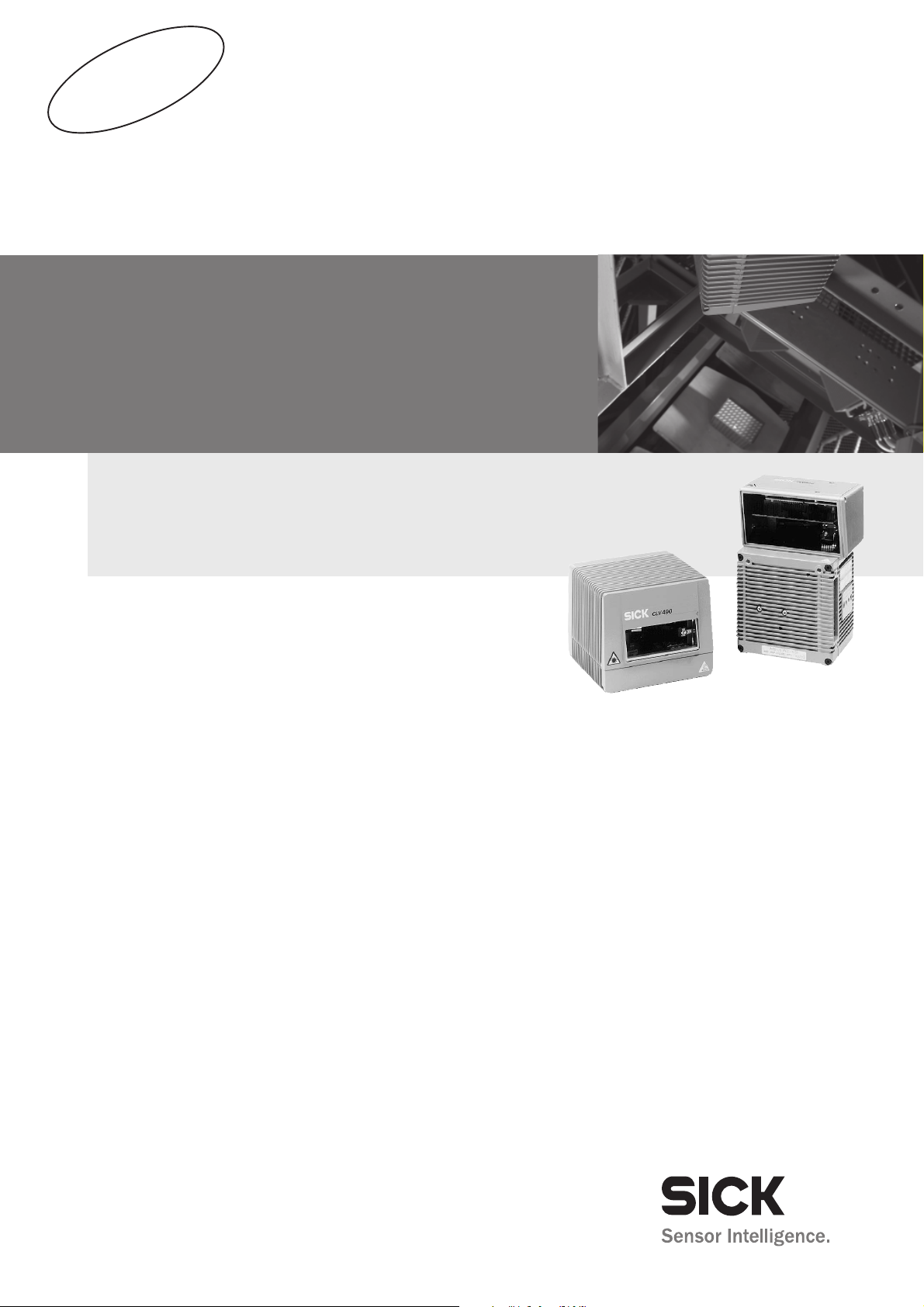
CDB420 and CDM490
CLV490
Bar Code Scanner
Advanced Line
OPERATING INSTRUCTIONS
Page 2

Operating Instructions
Software versions
CLV 490 Bar Code Scanner
Software versions
Software/Tool Function Version
CLV 490-0010/-0011 Firmware From V 3.5 O824
CLV 490-1010/-1011 Firmware From V 3.5 O824
CLV 490-6010/-6011 Firmware From V 3.5 O824
CLV 490-7010/-7011 Firmware From V 3.5 O824
CLV 490-2010/-2011 Firmware From V 3.5 O824
CLV 490-3010/-3011 Firmware From V 3.5 O824
CLV-Setup User interface (windows-based) From V 4.1 O508
CLV-Setup Help Online help (HTML) From V 4.1 O508
I-2 © SICK AG · Division Auto Ident · Germany · All rights reserved 8 009 993/O824/20-12-2004
Copyright
Copyright © 2004
SICK AG Waldkirch
Auto Ident, Reute Plant
Nimburger Strasse 11
79276 Reute
Germany
Trademarks
TM
Windows 95
Explorer
TM
are registered trademarks or trademarks of the Microsoft Corporation in the USA
TM
/98
, Windows NTTM, Windows 2000TM, Windows XPTM and Internet
and other countries.
Latest manual version
For the latest version of this manual (PDF), see www.sick.com.
Page 3

Operating Instructions
CLV 490 Bar Code Scanner
Quick Finder
CLV 490 Bar Code Scanner
Quick Finder
• What is delivered with the device
– Chapter 3.1.1 Scope of delivery, Page 3-1
• CAUTION!
– Chapter 2 Safety information, Page 2-1
• Mounting the device at the reading station
– Chapter 4 Installation, Page 4-1
• Connecting the device
– Chapter 5 Electrical installation, Page 5-1
• Overview of the device and its functions
– Chapter 3 Product description, Page 3-1
– Chapter 6.2 Default settings, Page 6-1
– Chapter 6.5 Operating modes and outputing the reading result, Page 6-39
– Chapter 9 Technical data, Page 9-1
– Chapter 10.3 Installing and operating the external parameter memory (connector co-
ver), Page 10-34
• Starting the device with the default settings
– Chapter 6.3 Quick start, Page 6-3
• Installing the "CLV-Setup" program
– Chapter 10.6 Installing and operating the "CLV-Setup" program, Page 10-43
• Adapting the device to the reading application
– Chapter 6.4 Configuring (parameterization) the CLV, Page 6-5
• Troubleshooting
– Chapter 8 Troubleshooting, Page 8-1
• Finding information
– Table of contents, Page I-5
– Index, Page 10 -93
8 009 993/O824/20-12-2004 © SICK AG · Division Auto Ident · Germany · All rights reserved I-3
Page 4

Quick Finder
Operating Instructions
CLV 490 Bar Code Scanner
Installation procedure (overview)
CLV in stand-alone configuration
Start/stop mode: Reading trigger via “Sensor“ switching input (default setting)
1. Check the delivery to make sure that none of the components is missing.
2. Mount the CLV at the reading station and align it with the object carrying the bar code.
3. Mount the CDB 420 or CDM 490 Connection Module.
4. Connect the CLV as followed:
CDB 420 Connection Module: using the cable no. 2 027 046. Alternatively, connect
the CLV using the external parameter memory no. 2 030 023.
CDM 490 Connection Module: using two cables no. 2 020 302. Alternatively, connect
the CLV using the external parameter memory no. 2 020 307.
5. Mount the sensor for starting/stopping the reading pulse.
6. Connect the reading pulse sensor to the "Sensor (1)" switching input in the CDB 420
or CDM 490.
7. Connect the host to the host interface in the CDB 420 or CDM 490.
8. Switch on the power supply to the CDB 420 or CDM 490.
The "Device Ready" LED lights up after the CLV has started.
CLV with external empty parameter memory connected (no. 2 020 307 or 2 030 023):
After the CLV has started, it copies the internal parameter set to the external parameter
memory if no CMC 400 parameter memory is available in the CDB 420/CDM 490.
Line scanner with oscillating mirror:
In the default setting, the CLV deflects the scan line around the position CW = 50 with
a frequency of 1 Hz and an oscillating amplitude of max. ±20° (±40 CW).
9. Switch on your PC and start Windows
10. Install the "CLV-Setup" software and the online CLV-Setup Help from the CD-ROM
("Manuals & Software") on your PC.
11. Connect the PC to the terminal interface of the CLV.
To do so, connect a 3-core RS 232 data cable (null modem cable), e. g. no. 2 014 054
to the "Aux" plug in the CDB 420 or CDM 490.
12. Start the "CLV-Setup" program.
CLV-Setup establishes communication with the CLV and uploads the parameter set.
The parameters are then displayed on the tabs.
13. Carry out a test read using test bar codes (clock the CLV accordingly).
Display the reading result in the Terminal Emulator window of the "CLV-Setup" program.
14. Configure the CLV for the application using the settings on the tabs in CLV-Setup.
Copy (download) the modified parameter set to the CLV temporarily.
Do not switch off the power to the CDB 420 or CDM 490 (CLV)!
15. Test the application under realistic conditions.
16. Check whether the data is transmitted correctly between the CLV and host.
17. If necessary, correct and optimize the parameter values.
Copy (download) the parameter set permanently to the CLV.
CLV with external parameter memory connected:
Copy the modified parameter set to the external parameter memory when CLV-Setup
asks you for confirmation.
18. Save the parameter set as a configuration file "*.scl" in the "CLV-Setup" program.
TM
(minimum requirement: Windows 95TM).
The CLV can then be operated with the application-specific settings.
I-4 © SICK AG · Division Auto Ident · Germany · All rights reserved 8 009 993/O824/20-12-2004
Page 5

Operating Instructions
CLV 490 Bar Code Scanner
Contents
Table of contents
1 Notes on this document............................................................................................ 1-1
1.1 Purpose ....................................................................................................................................... 1-1
1.2 Target audience........................................................................................................................ 1-1
1.2.1 Mounting, electrical installation, maintenance and replacement.................... 1-1
1.2.2 Startup, operation and configuration ......................................................................... 1-1
1.3 Information content................................................................................................................. 1-2
1.4 Symbols....................................................................................................................................... 1-2
2 Safety information....................................................................................................... 2-1
2.1 Authorized users ...................................................................................................................... 2-1
2.1.1 Mounting and maintenance .......................................................................................... 2-1
2.1.2 Electrical installation and replacement ..................................................................... 2-1
2.1.3 Startup, operation and configuration ......................................................................... 2-1
2.2 Intended use.............................................................................................................................. 2-1
2.3 General safety instructions and protection measures.............................................. 2-2
2.4 Quick stop and quick restart................................................................................................ 2-4
2.4.1 Stopping the CLV............................................................................................................... 2-4
2.4.2 Restarting the CLV............................................................................................................ 2-4
2.5 Environmental information....................................................................................................2-4
2.5.1 Power requirements.........................................................................................................2-4
2.5.2 Disposal after removal from service.......................................................................... 2-4
3 Product description .................................................................................................... 3-1
3.1 Design .......................................................................................................................................... 3-1
3.1.1 Scope of delivery............................................................................................................... 3-1
3.1.2 Variants................................................................................................................................. 3-1
3.1.3 System requirements for stand-alone configuration........................................... 3-2
3.1.4 Product features and functions (overview) ............................................................. 3-3
3.1.5 Design ................................................................................................................................... 3-5
3.2 Method of operation............................................................................................................... 3-6
3.2.1 Autofocus function............................................................................................................ 3-7
3.2.2 Event-controlled dynamic focus control ................................................................... 3-8
3.2.3 Reading modes in stand-alone configuration......................................................... 3-8
3.2.4 Scan procedure variants................................................................................................ 3-9
3.2.5 Additional components.................................................................................................3-10
3.3 Indicators and control elements ......................................................................................3-10
3.3.1 Control elements.............................................................................................................3-10
3.3.2 Function of the LEDs......................................................................................................3-11
4 Installation..................................................................................................................... 4-1
4.1 Installation sequence ............................................................................................................. 4-1
4.2 Preparations............................................................................................................................... 4-1
4.2.1 Required components..................................................................................................... 4-1
4.2.2 Required accessories...................................................................................................... 4-1
4.2.3 Required auxiliary parts .................................................................................................. 4-1
4.2.4 Replacing the laser warning label ............................................................................... 4-2
4.2.5 Selecting the mounting location .................................................................................. 4-2
4.2.6 Mounting accessories ..................................................................................................... 4-3
4.2.7 Distance between the CLV and the bar code........................................................ 4-4
4.2.8 Count direction of the code position CP and code angle CW.......................... 4-6
4.3 Mounting and adjusting the device................................................................................... 4-7
4.3.1 Mounting the CLV.............................................................................................................. 4-7
4.3.2 Adjusting the CLV .............................................................................................................. 4-8
4.3.3 Adjusting mode .................................................................................................................. 4-9
4.4 Mounting the external components................................................................................4-11
4.4.1 Mounting the CDB 420 or CDM 490 Connection Module .............................4-11
4.4.2 Mounting the external reading pulse sensor........................................................4-11
4.4.3 Installing incremental encoder ...................................................................................4-12
8 009 993/O824/20-12-2004 © SICK AG · Division Auto Ident · Germany · All rights reserved I-5
Page 6

Contents
4.4.4 Mounting the sensors for detecting the object distance................................4-13
4.5 Dismantling the device........................................................................................................ 4-14
5 Electrical installation ................................................................................................. 5-1
5.1 Installation sequence.............................................................................................................5-1
5.1.1 SICK Connection Modules (overview)......................................................................5-1
5.2 Electrical connections and cables .....................................................................................5-1
5.2.1 Wire cross-sections ..........................................................................................................5-1
5.2.2 Prefabricated cables (overview) .................................................................................. 5-2
5.2.3 Connections/cables for the CDB 420 Connection Modules............................5-3
5.2.4 Connections/cables for the CDM 490 Connection Module.............................5-5
5.2.5 Connections/cables for a non-SICK power pack..................................................5-6
5.3 Connector pin assignment....................................................................................................5-7
5.3.1 Terminals on the CLV.......................................................................................................5-7
5.3.2 Cable no. 2 027 046 (connector cover)
Cable no. 2 030 023 (connector cover with parameter memory)................5-8
5.3.3 Cable no. 2 020 307 (connector cover with parameter memory)................5-9
5.3.4 Cable no. 2 033 126/2 033 127 (connector cover with
parameter memory) ...................................................................................................... 5-10
5.3.5 Cable no. 2 030 065/2 031 034 (connector cover with
parameter memory) ...................................................................................................... 5-11
5.3.6 Cable no. 2 027 543 (connector cover with parameter memory)............. 5-13
5.3.7 Cable no. 2 020 303....................................................................................................5-14
5.3.8 Cable no. 2 020 264....................................................................................................5-14
5.3.9 Cable no. 2 020 981 (connector cover with parameter memory)............. 5-15
5.3.10 Cable no. 2 021 267 (connector cover)...............................................................5-16
5.4 Preparations for electrical installation............................................................................5-17
5.4.1 Requirements for the host interface....................................................................... 5-17
5.4.2 Supply voltage ................................................................................................................. 5-17
5.4.3 Non-SICK Power supply unit/connections without the
Connection Module........................................................................................................ 5-18
5.5 Electrical installation procedure.......................................................................................5-19
5.5.1 Individual steps................................................................................................................ 5-19
5.5.2 Tools....................................................................................................................................5-19
5.5.3 Connecting the supply voltage ..................................................................................5-19
5.5.4 Connecting the host interface ...................................................................................5-21
5.5.5 Connecting the CAN interface ...................................................................................5-22
5.5.6 Connecting the PC..........................................................................................................5-22
5.5.7 Connecting the "Sensor" switching input.............................................................. 5-23
5.5.8 Connecting the "IN 0" to "IN 4" switching inputs............................................... 5-24
5.5.9 Connecting the "Result 1" to "Result 4" switching outputs...........................5-27
6 Operation ....................................................................................................................... 6-1
6.1 Overview of steps for starting up the CLV ......................................................................6-1
6.2 Default settings.........................................................................................................................6-1
6.2.1 Default settings of the line scanner CLV 490 (all variants)...............................6-2
6.2.2 Default settings of the line scanner with oscillating mirror
CLV 490 (all variants) ......................................................................................................6-2
6.3 Quick start ...................................................................................................................................6-3
6.3.1 Starting up the CLV with the factory default settings...........................................6-3
6.4 Configuring (parameterization) the CLV...........................................................................6-5
6.4.1 Configuring the CLV via the user interface of CLV-Setup...................................6-5
6.4.2 Function of the tabs in CLV-Setup (overview) ........................................................6-7
6.4.3 Parameterizing example .................................................................................................6-9
6.4.4 Guide to parameterization menu.................................................................................6-9
6.5 Operating modes and outputing the reading result .................................................6-39
6.5.1 Reading mode (standard operating mode).......................................................... 6-39
6.5.2 Percentage evaluation.................................................................................................. 6-42
6.5.3 Adjusting mode................................................................................................................ 6-44
Operating Instructions
CLV 490 Bar Code Scanner
I-6 © SICK AG · Division Auto Ident · Germany · All rights reserved 8 009 993/O824/20-12-2004
Page 7

Operating Instructions
CLV 490 Bar Code Scanner
Contents
6.5.4 Background teach-in......................................................................................................6-45
6.5.5 Show CP-limits..................................................................................................................6-47
6.5.6 Background Analysis......................................................................................................6-48
6.5.7 I/O monitor in increment trigger ................................................................................6-49
6.5.8 Displaying and editing operating data .....................................................................6-54
6.5.9 Reading diagnosis...........................................................................................................6-55
6.5.10 Monitor Host Interface..................................................................................................6-55
6.5.11 Auxiliary input ....................................................................................................................6-57
6.5.12 Code statistics for RDT 400 .......................................................................................6-57
6.5.13 Self-test...............................................................................................................................6-58
6.5.14 Executing CLV functions interactively......................................................................6-59
6.6 CLV messages........................................................................................................................6-60
6.6.1 Displaying messages.....................................................................................................6-60
6.6.2 Error messages ...............................................................................................................6-61
6.7 Switching off the CLV............................................................................................................6-61
7 Maintenance ................................................................................................................. 7-1
7.1 Cleaning the CLV during operation.................................................................................... 7-1
7.2 Maintenance.............................................................................................................................. 7-2
7.3 Disposal....................................................................................................................................... 7-2
8 Troubleshooting ........................................................................................................... 8-1
8.1 Overview of possible errors and malfunctions ............................................................. 8-1
8.1.1 Mounting errors ................................................................................................................. 8-1
8.1.2 Electrical installation errors............................................................................................ 8-1
8.1.3 Parameter errors............................................................................................................... 8-1
8.1.4 Malfunctions........................................................................................................................ 8-1
8.2 Monitoring error and malfunctions.................................................................................... 8-1
8.3 Error messages ........................................................................................................................ 8-2
8.3.1 CLV without external parameter memory................................................................ 8-2
8.3.2 LED error messages for the external parameter memory
(connector cover).............................................................................................................. 8-3
8.3.3 Messages for errors accessing the external parameter memory
(connector cover).............................................................................................................. 8-5
8.4 ST error status in the reading result of a bar code..................................................... 8-7
8.5 Troubleshooting........................................................................................................................ 8-9
8.5.1 General malfunctions: CLV not ready........................................................................ 8-9
8.5.2 Malfunctions in Reading mode: reading trigger errors......................................8-10
8.5.3 Malfunctions in Reading mode: result output errors.........................................8-14
8.5.4 Malfunctions in Reading mode: errors in the result status output...............8-18
8.5.5 Malfunctions in Reading mode: oscillating mirror errors..................................8-19
8.6 SICK Support...........................................................................................................................8-20
9 Technical data.............................................................................................................. 9-1
9.1 Data sheet CLV 490-0010/-2010/-6010 bar code scanner............................... 9-1
9.2 Data sheet CLV 490-1010/-3010/-7010 bar code scanner............................... 9-2
9.3 Data sheet CLV 490-0011 /-2011/-6011 bar code scanner.............................. 9-2
9.4 Data sheet CLV 490-1011/-3011/-7011 bar code scanner............................... 9-3
9.5 Dimensioned drawings – CLV............................................................................................. 9-3
9.5.1 Line scanner (standard device) without /with heater ......................................... 9-3
9.5.2 Line scanner with oscillating mirror (without/with heater)................................. 9-4
10 Appendix ..................................................................................................................... 10-1
10.1 Overview....................................................................................................................................10-1
10.2 Specification diagrams.........................................................................................................10-1
10.2.1 Reading conditions for all diagrams.........................................................................10-1
10.2.2 Overview of diagrams....................................................................................................10-2
10.2.3 Standard density: Reading performance data of line scanner......................10-3
10.2.4 Standard density: Reading performance data of line scanner
with oscillating mirror .....................................................................................................10-
10.2.5 High density: Reading performance data of line scanner ............................10-16
9
8 009 993/O824/20-12-2004 © SICK AG · Division Auto Ident · Germany · All rights reserved I-7
Page 8

Contents
10.2.6 High density: Reading performance data line scanner
with oscillating mirror.................................................................................................. 10-21
10.2.7 Low density: Reading performance data of line scanner.............................10-27
10.2.8 Low density: Reading performance data of line scanner with
oscillating mirror........................................................................................................... 10-31
10.3 Installing and operating the external parameter memory
(connector cover)...............................................................................................................10-34
10.3.1 Function of the external parameter memory ....................................................10-35
10.3.2 Installation and electrical connection................................................................... 10-36
10.3.3 Operation ........................................................................................................................10-36
10.3.4 Switching on the device for the first time...........................................................10-37
10.3.5 Adjusting the parameter set in the external parameter memory
(connector cover) after it has been downloaded to the CLV..................... 10-37
10.3.6 Meaning of the LEDs.................................................................................................. 10-38
10.3.7 Error messages............................................................................................................10-38
10.3.8 Replacing a CLV ...........................................................................................................10-39
10.4 Optional heating.................................................................................................................. 10-40
10.4.1 Features.......................................................................................................................... 10-40
10.4.2 Design.............................................................................................................................. 10-40
10.4.3 Function........................................................................................................................... 10-40
10.4.4 Electrical installation ...................................................................................................10-41
10.4.5 Outdoor applications .................................................................................................. 10-41
10.5 System messages .............................................................................................................10-42
10.5.1 CLV without external parameter memory .......................................................... 10-42
10.5.2 CLV with external parameter memory connected .......................................... 10-42
10.6 Installing and operating the "CLV-Setup" program................................................ 10-43
10.6.1 Preparations .................................................................................................................. 10-43
10.6.2 Installing the software................................................................................................ 10-43
10.6.3 Starting CLV-Setup...................................................................................................... 10-46
10.6.4 User interface................................................................................................................ 10-48
10.6.5 Functions ........................................................................................................................ 10-49
10.6.6 Hot keys ..........................................................................................................................10-49
10.6.7 Opening and closing tabs.........................................................................................10-50
10.6.8 Online help – CLV-Setup Help ................................................................................ 10-50
10.6.9 Transferring parameter sets between CLV-Setup and the CLV ................10-51
10.6.10 Unknown parameters................................................................................................. 10-51
10.6.11 Log file in the Terminal Emulator ...........................................................................10-52
10.6.12 Starting CLV-Setup with an "INI file" as an argument....................................10-52
10.6.13 The CLV Assistant........................................................................................................10-52
10.7 Configuring a CLV with command strings.................................................................. 10-53
10.8 Calculating parameter values for setting the CLV.................................................. 10-55
10.8.1 Calculating the number of scans (for standard decoder)............................10-55
10.8.2 Calculating the start position and mirror speed for the forward
and return phase of the One-Shot function ...................................................... 10-57
10.8.3 Calculating the necessary bar code distance if several bar
codes are read on each object..............................................................................10-58
10.9 Tables .....................................................................................................................................10-59
10.9.1 Calculating the code length of a bar code......................................................... 10-59
10.10 Discussion of a parameterization example.............................................................. 10-60
10.10.1 Application Conditions ............................................................................................... 10-60
10.10.2 Purpose of this discussion.......................................................................................10-60
10.10.3 Instructions for solution – step by step.............................................................. 10-60
10.10.4 Important clarifications..............................................................................................10-61
10.10.5 Mounting and electrical connection ..................................................................... 10-61
10.10.6 Parameterize the CLV with the "CLV-Setup" program .................................. 10-62
10.10.7 Testing the application ..............................................................................................10-68
10.11 Special applications and procedures ......................................................................... 10-69
Operating Instructions
CLV 490 Bar Code Scanner
I-8 © SICK AG · Division Auto Ident · Germany · All rights reserved 8 009 993/O824/20-12-2004
Page 9

Operating Instructions
CLV 490 Bar Code Scanner
Contents
10.11.1 Auxiliary input via terminal interface......................................................................10-69
10.11.2 Connection to Profibus DP........................................................................................10-72
10.11.3 Connection to the DeviceNet ..................................................................................10-72
10.11.4 Connection to Ethernet TCP/IP...............................................................................10-72
10.11.5 Building a CAN Scanner Network...........................................................................10-72
10.11.6 Integration in an OPS reading system..................................................................10-72
10.12 Replacing a CLV (copying the parameter set).........................................................10-73
10.12.1 Downloading the parameter set.............................................................................10-73
10.12.2 Importing the parameter set from the external memory..............................10-74
10.13 Accessories...........................................................................................................................10-75
10.13.1 Mounting accessories ................................................................................................10-75
10.13.2 Connection modules...................................................................................................10-75
10.13.3 Extensions for connection modules......................................................................10-76
10.13.4 Cables, external parameter memories in connector cover,
connector covers .........................................................................................................10-77
10.13.5 Plug-in connections .....................................................................................................10-80
10.13.6 Reading pulse generators.........................................................................................10-80
10.13.7 Incremental encoder...................................................................................................10-81
10.14 Dimensioned drawings of the accessories...............................................................10-81
10.14.1 Angle bracket, single no. 2 013 824...................................................................10-81
10.14.2 Articulated bracket No. 2 018 435 ......................................................................10-81
10.14.3 Quick clamping device No. 2 016 110...............................................................10-81
10.15 Supplementary documentation.....................................................................................10-82
10.15.1 CLV Connect (from version 1.9) ...........................................................................10-82
10.16 Glossary..................................................................................................................................10-83
10.17 EC Declaration of Conformity .........................................................................................10-92
10.18 Index ........................................................................................................................................10-93
10.19 Bar code example ..............................................................................................................10-99
8 009 993/O824/20-12-2004 © SICK AG · Division Auto Ident · Germany · All rights reserved I-9
Page 10

Operating Instructions
Figures and tables
CLV 490 Bar Code Scanner
Abbreviations
AMV/S Connection Module with signal distribution/with additional power supply pack
BMV/S Bus Connection module with signal distribution/with additional power supply
CAN Controller Area Network (standard field bus system with message-orientated data ex-
change protocol)
CLV Code-Leser V-Prinzip.
DC Distance Configuration
DOF Depth Of Field
EEPROM Electrically Erasable Programmable Read Only Memory
HD High Density
HTML Hyper Text Markup Language (page-description language on the internet)
LED Light Emitting Diode
MTBF Mean Time Between Failure
PLC Programmable Logic Controller
RAM Ramdom Acces Memory
ROM Read Only Memory
RTF Rich Text Format (standard document format with format descriptions)
SMART SICK Modular Advanced Recognition T
echnology
Tables
Table 3-1: CLV variants ........................................................................................................................ 3-1
Table 3-2: Meaning of LEDs: CLV without external parameter memory .........................3-11
Table 3-3: Meaning of LEDs: CLV with external parameter memory in
the connector cover.......................................................................................................3-12
Table 4-1: Permissible reading angles between the scan line and bar code ................. 4-5
Table 5-1: Connection Modules for the CLV ................................................................................ 5-1
Table 5-2: Cables for connecting the CLV..................................................................................... 5-2
Table 5-3: Pin assignment of the 15-pin D Sub HD "Host/Term" plug ............................. 5-7
Table 5-4: Pin assignment of the 15-pin D Sub HD "I/O" socket........................................ 5-7
Table 5-5: Pin assignment: 15-pin D Sub HD plug of the cable no. 2 027 046/
no. 2 030 023...................................................................................................................5-8
Table 5-6: Pin assignment: 15-pin D Sub HD plug of the cable no. 2 020 307........... 5-9
Table 5-7: Pin assignment: 15-pin D Sub HD socket of the cable no. 2 020 307...... 5-9
Table 5-8: Pin assignment: 15-pin D Sub HD plug of the cable no. 2 033 126/
no. 2 033 127.................................................................................................................5-10
Table 5-9: Pin assignment: open end of the cable no. 2 033 126/
no. 2 033 127.................................................................................................................5-10
Table 5-10: Pin assignment: 15-pin D Sub HD plug of the cable no. 2 030 065/
no. 2 031 034.................................................................................................................5-11
Table 5-11: Pin assignment: 15-pin D Sub HD socket of the cable
no. 2 030 065/no. 2 031 034.................................................................................5-11
Table 5-12: Pin assignment: open end of the cable no. 2 030 065/
no. 2 031 034.................................................................................................................5-12
Table 5-13: Pin assignment: 15-pin D Sub HD plug of the cable no. 2 027 543.........5-13
Table 5-14: Pin assignment: 15-pin D Sub HD socket of the cable no. 2 027 543....5-13
Table 5-15: Pin assignment: 15-pin D Sub HD socket/wire colors of cable
no. 2 020 303.................................................................................................................5-14
Table 5-16: Pin assignment: 15-pin D Sub HD plug/wire colors of cable
no. 2 020 264.................................................................................................................5-14
I-10 © SICK AG · Division Auto Ident · Germany · All rights reserved 8 009 993/O824/20-12-2004
Page 11

Operating Instructions
Figures and tables
CLV 490 Bar Code Scanner
Table 5-17: Wire colors of cable no. 2 020 981, cable 1 ("Host/Term"
connection) .......................................................................................................................5-15
Table 5-18: Wire colors of cable no. 2 020 981, cable 2 ("I/O" connection)................5-15
Table 5-19: Wire colors of cable no. 2 021 267, cable 1 (connection for data
and function interfaces) ............................................................................................... 5-16
Table 5-20: Wire colors of cable no. 2 021 267, cable 2 (connection for
power supply)...................................................................................................................5-16
Table 5-21: Maximum cable lengths between the CLV and host ........................................5-17
Table 5-22: Power consumption of the CLV.................................................................................5-17
Table 5-23: Power-up delay as a function of the device number GN ................................5-17
Table 5-24: Communication parameters for the host interface (default setting) ..........5-21
Table 5-25: Characteristic data of the "Sensor" switching input..........................................5-23
Table 5-26: Pin assignment for "IN 0" to IN 4" switching inputs..........................................5-25
Table 5-27: Characteristic data of the "IN 0" to "IN 4" switching inputs ..........................5-25
Table 5-28: Dynamic focus control: switching inputs/distance configuration
assignment table ............................................................................................................5-25
Table 5-29: Combination of the functions of the "IN 0" to "IN 4" switching inputs...... 5-26
Table 5-30: Pin assignment for "Result 1" to "Result 4" switching outputs .................... 5-27
Table 5-31: Characteristic data of the "Result 1" to "Result 4" switching outputs.......5-27
Table 6-1: Extract: Default parameter settings of the line scanner
CLV 490-0010/-0011....................................................................................................6-2
Table 6-2: Extract: Default parameter settings of the line scanner with
oscillating mirror CLV 490.............................................................................................. 6-2
Table 6-3: Reading distances for default settings......................................................................6-4
Table 6-4: Guide: Configuring the reading area........................................................................6-11
Table 6-5: Guide: Selecting the focus control mode..............................................................6-12
Table 6-6: Guide: Configuring the autofocus function (part 1)...........................................6-13
Table 6-7: Configuring the autofocus function (part 2) .........................................................6-15
Table 6-8: Guide: Configuring focus position switchover......................................................6-16
Table 6-9: Guide: Configuring oscillating mirror functions ....................................................6-18
Table 6-10: Overview: CLV applications in stand-alone configuration or in
arrangement with OTS 400........................................................................................6-22
Table 6-11: Guide: Parameterizing the reading trigger for start/stopp mode in
stand-alone configuration............................................................................................6-23
Table 6-12: Guide: Parameterzing internal object tracking..................................................... 6-28
Table 6-13: Guide: Parameterizing the reading mode for tracking mode in
stand-alone configuration............................................................................................6-30
Table 6-14: Guide: Parameterizing focus control in CLV for master/slaves
arrangement with
OTC 400.............................................................................................................................6-31
Table 6-15: Guide: Parameterizing reading trigger in the CLV for master/slave
arrangement with
OTC 400.............................................................................................................................6-32
Table 6-16: Guide: Parameterizing slave mode in the CLV for arrangement
with OTC 400 (master).................................................................................................6-32
Table 6-17: Guide: Parameterizing operation mode in the OTC 400 for
master/slaves arrangement.......................................................................................6-33
Table 6-18: Guide: Parameterizing focus control in CLV for object tracking
mode with OTC 400 ......................................................................................................6-34
Table 6-19: Guide: Parameterizing reading trigger in the CLV for object tracking
mode with OTC 400 ......................................................................................................6-35
Table 6-20: Guide: Parameterizing tracking in the CLV for object tracking
mode with OTC 400 ......................................................................................................6-35
Table 6-21: Guide: Parameterizing slave mode in the CLV for object tracking
mode with OTC 400 ......................................................................................................6-36
Table 6-22: Guide: Parameterizing tracking mode in the OTC 400 ....................................6-36
Table 6-23: Guide: Parameterizing the laser timeout ...............................................................6-37
8 009 993/O824/20-12-2004 © SICK AG · Division Auto Ident · Germany · All rights reserved I-11
Page 12

Operating Instructions
Figures and tables
CLV 490 Bar Code Scanner
Table 6-24: Guide: Parameterizing the separation of identical bar codes........................6-37
Table 6-25: "Monitor Host Interface" function.............................................................................6-55
Table 8-1: Error messages output on the terminal interface ................................................ 8-2
Table 8-2: LED error messages for access to the external parameter
memory (connector cover)............................................................................................ 8-3
Table 8-3: Messages for problems accessing the external parameter
memory (connector cover)............................................................................................ 8-5
Table 8-4: Meaning of the ST error status in the reading result .......................................... 8-7
Table 8-5: Troubleshooting: restoring operation (Reading mode)....................................... 8-9
Table 8-6: Troubleshooting: reading trigger errors in Reading mode
(CLV in stand-alone configuration) ...........................................................................8-10
Table 8-7: Troubleshooting: reading trigger errors in Reading mode
(CLV integrated in OTS 400 Omni Tracking System) ........................................8-13
Table 8-8: Troubleshooting: result output errors in Reading mode
(CLV in stand-alone configuration) ...........................................................................8-14
Table 8-9: Troubleshooting: result output errors in Reading mode
(CLV integrated in the OTS 400 Omni Tracking System) ................................8-17
Table 8-10: Troubleshooting: errors in the result status output in Reading mode ........8-18
Table 8-11: Troubleshooting: oscillating mirror errors in Reading mode ...........................8-19
Table 9-1: Technical specifications of the CLV 490-0010/-2010/-6010....................... 9-1
Table 9-2: Technical specifications of the CLV 490-1010/-3010/-7010....................... 9-2
Table 9-3: Technical specifications of the CLV 490-0011/-2011/-6011....................... 9-2
Table 9-4: Technical specifications of the CLV 490-1011/-3011/-7011....................... 9-3
Table 10-1: Reading conditions for specification diagrams ....................................................10-1
Table 10-2: Overview of specification diagrams for the line scanner .................................10-2
Table 10-3: Overview of specification diagrams for the line scanner with
oscillating mirror...............................................................................................................10-2
Table 10-4: Types of the external parameter memory in the connector cover ...........10-34
Table 10-5: CLV system messages ..............................................................................................10-42
Table 10-6: Additional CLV system messages for the connected
parameter memory .....................................................................................................10-42
Table 10-7: Default settings in CLV-Setup..................................................................................10-46
Table 10-8: Formulas for calculating the code length of a bar code ...............................10-59
Table 10-9: Communication parameters on the terminal/PC for the
auxiliary input .................................................................................................................10-71
Table 10-10: Communication parameter settings for the SICK Hand-held
Scanner from the IT 38xx/46xx/48xx/58xx series........................................10-71
Table 10-11: Accessories: mounting accessories .....................................................................10-75
Table 10-12: Accessories: connection modules.........................................................................10-75
Table 10-13: Accessories: Extensions for connection modules...........................................10-76
Table 10-14: Accessories: Cables and connector covers for CLVs without heater......10-77
Table 10-15: Accessories: Cables and connector covers for CLVs with heater ............10-79
Table 10-16: Accessories: plug-in connections ..........................................................................10-80
Table 10-17: Accessories: incremental encoder........................................................................10-81
Table 10-18: Supplementary documentation..............................................................................10-82
I-12 © SICK AG · Division Auto Ident · Germany · All rights reserved 8 009 993/O824/20-12-2004
Page 13

Operating Instructions
Figures and tables
CLV 490 Bar Code Scanner
Figures
Fig. 2-1: Laser warning labels on the CLV.....................................................................................2-3
Fig. 3-1: Design of the CLV 490 .......................................................................................................3-5
Fig. 3-2: Block diagram: CLV functions...........................................................................................3-6
Fig. 3-3: Optimization of the depth of field for the object .......................................................3-7
Fig. 3-4: Dynamic focus control: classification of the reading range in distance
configurations.........................................................................................................................3-8
Fig. 3-5: Reading modes of the CLV in stand-alone configuration ...................................... 3-9
Fig. 3-6: LEDs........................................................................................................................................3-11
Fig. 4-1: Line scanner: replacing the laser warning labels......................................................4-2
Fig. 4-2: Line scanner: position of the securing threads on the CLV..................................4-3
Fig. 4-3: Line scanner: Mounting possibilities of the CLV........................................................4-3
Fig. 4-4: Scanning methods: alignment with bar code and conveyor direction..............4-4
Fig. 4-5: Definition of the reading distance "a" and of the aperture angle a...................4-4
Fig. 4-6: Line scanner: Reading angle between the scan line and the bar code...........4-5
Fig. 4-7: Avoiding surface reflections: Angle between the emitted light and
the bar code (tilted away from the vertical axis).......................................................4-5
Fig. 4-8: Count direction of the code position CP in the scan line and of the
code angle CW for the oscillating mirror ......................................................................4-6
Fig. 4-9: Line scanner: scan line in Adjusting mode..................................................................4-9
Fig. 4-10: Line scanner: mounting example for the external reading pulse sensor .....4-11
Fig. 4-11: Mounting example for object distance detection ..................................................4-13
Fig. 5-1: Block diagram: Connection of the CLV 490 to the CDB 420
connection module...............................................................................................................5-3
Fig. 5-2: Block diagram: Connection of the CLV 490 to the CDM 490
connection module...............................................................................................................5-5
Fig. 5-3: Connecting the host interface.......................................................................................5-21
Fig. 5-4: Connecting the terminal interface ...............................................................................5-22
Fig. 5-5: Connections of the "Sensor" switching input..........................................................5-23
Fig. 5-6: Connections of the "IN 0" to "IN 4" switching inputs ..........................................5-24
Fig. 5-7: Connections of the "Result 1" to "Result 4" switching outputs.......................5-27
Fig. 6-1: Bar code pattern (Code 39; module width 0.35 mm (11.8 mil);
Print ratio 2:1) ........................................................................................................................6-4
Fig. 6-2: Narrowing the reading space using limit values.....................................................6-10
Fig. 6-3: Narrowing the autofocus range using limit values ................................................6-15
Fig. 6-4: Oscillating mirror: "Oscillating with fixed amplitude" mode ................................ 6-19
Fig. 6-5: Oscillating mirror: "Oscillating with variable amplitude" mode ..........................6-20
Fig. 6-6: One-Shot: Object tracking (bar code read from front).........................................6-21
Fig. 6-7: CLV-Setup: Displaying the reading result of the termianl interface
in the Terminal Emulator .................................................................................................6-40
Fig. 6-8: Reading result of the terminal interface: structure for "Good Read"............. 6-41
Fig. 6-9: Reading result of the terminal interface: structure for "No Read" ..................6-41
Fig. 6-10: CLV-Setup: Displaying the percentage evaluation in the
Terminal Emulator..............................................................................................................6-43
Fig. 6-11: CLV-Setup: Dialog window for running the background teach-in.....................6-45
Fig. 6-12: CLV-Setup: Display of th learned background ........................................................6-46
Fig. 6-13: Appearance of scan line in the "Show CP-limits" mode ..................................... 6-47
Fig. 6-14: CLV-Setup: Example of output in the "Background Analysis" dialog box.....6-48
Fig. 6-15: CLV-Setup: Selection of the signals to be displayed in I/O Monitoring......... 6-50
Fig. 6-16: CLV-Setup: Example of output in the "I/O Monitoring" dialog box..................6-51
Fig. 6-17: CLV-Setup: "Operating Data" dialog box...................................................................6-54
Fig. 6-18: CLV-Setup: Displaying the reading result of the host interface in
the Terminal Emulator with direction identifier at the beginning
(in this case: O = Output)................................................................................................ 6-56
Fig. 6-19: CLV-Setup: Displaying the self-test result in the Terminal Emulator .............. 6-58
Fig. 6-20: CLV-Setup: Dialog box for executing Show limits ..................................................6-59
Fig. 6-21: CLV-Setup: Displaying the system messages in the Terminal
8 009 993/O824/20-12-2004 © SICK AG · Division Auto Ident · Germany · All rights reserved I-13
Page 14

Operating Instructions
Figures and tables
CLV 490 Bar Code Scanner
Emulator when starting the CLV....................................................................................6-60
Fig. 7-1: Cleaning the reading window ........................................................................................... 7-1
Fig. 7-2: Cleaning the external optical sensors (reading pulse generator,
object-height detector)....................................................................................................... 7-2
Fig. 9-1: Dimensions of the CLV 490 line scanner, front reading window....................... 9-3
Fig. 9-2: Dimensions of the CLV 490: line scanner with oscillating mirror,
side reading window............................................................................................................ 9-4
Fig. 10-1: CLV 490-0010/-0011 (Standard density): Reading field height as
a function of the reading distance and resolution.................................................10-3
Fig. 10-2: CLV 490-0010/-0011 (Standard density): Min. and Max. reading
distance (measured radially) as a function of the focus position at a
resolution of 0.35 mm (13.8 mil) and an aperture angle of
Fig. 10-3: CLV 490-0010/-0011 (Standard density): Min. and Max. reading
distance (measured radially) as a function of the focus position at a
resolution of 0.35 mm (13.8 mil) and an aperture angle of
Fig. 10-4: CLV 490-0010/-0011 (Standard density): Min. and Max. reading
distance (measured radially) as a function of the focus position at a
resolution of 0.50 mm (19.7 mil) and an aperture angle of
Fig. 10-5: CLV 490-0010/-0011 (Standard density): Min. and Max. reading
distance (measured radially) as a function of the focus position at a
resolution of 0.50 mm (19.7 mil) and an aperture angle of
Fig. 10-6: Characteristics field CLV 490-0010/-0011 (Standard density): Scanning
frequency as a function of the radial reading distance and resolution .........10-8
Fig. 10-7: CLV 490-1010/-1011 (Standard density): Reading field height as a
function of the reading distance and resolution....................................................10-9
Fig. 10-8: CLV 490-1010/-1011 (Standard density): Min. and Max. reading
distance (measured radially) as a function of the focus position at a
resolution of 0.35 mm (13.8 mil) and an aperture angle of
Fig. 10-9: CLV 490-1010/-1011 (Standard density): Min. and Max. reading
distance (measured radially) as a function of the focus position at a
resolution of 0.35 mm (13.8 mil) and an aperture angle of
Fig. 10-10: CLV 490-1010/-1011 (Standard density): Min. and Max. reading
distance (measured radially) as a function of the focus position at a
resolution of 0.50 mm (19.7 mil) and an aperture angle of
Fig. 10-11: CLV 490-1010/-1011 (Standard density): Min. and Max. reading
distance (measured radially) as a function of the focus position at a
resolution of 0.50 mm (19.7 mil) and an aperture angle of
Fig. 10-12: Characteristics field CLV 490-1010/-1011 (Standard density):
Scanning frequency as a function of the radial reading distance
and resolution...................................................................................................................10-14
Fig. 10-13: CLV 490-1010/-1011 (Standard density): deflection range as a
function of radial reading distance, deflection angle and resolution ...........10-15
Fig. 10-14: CLV 490-2010/-2011 (High density): Reading field height as a
function of the reading distance and resolution..................................................10-16
Fig. 10-15: CLV 490-2010/-2011 (High density): Min. and Max. reading
distance (measured radially) as a function of the focus position at a
resolution of 0.25 mm (9.8 mil) and an aperture angle of
Fig. 10-16: CLV 490-2010/-2011 (High density): Min. and Max. reading distance
(measured radially) as a function of the focus position at a resolution
of 0.35 mm (13.8 mil) and an aperture angle of
Fig. 10-17: CLV 490-2010/-2011 (High density): Min. and Max. reading distance
(measured radially) as a function of the focus position at a resolution
of 0.35 mm (13.8 mil) and an aperture angle of
Fig. 10-18: Characteristics field CLV 490-2010/-2011 (High density): Scanning
frequency as a function of the radial reading distance and resolution ......10-20
Fig. 10-19: CLV 490-3010/-3011 (High density): Reading field height as a
function of the reading distance and resolution..................................................10-21
α =40° .............................10-18
α =56° .............................10-19
α =40° ...........10-4
α =56° ...........10-5
α =40° ...........10-6
α =56° ...........10-7
α =40° ........10-10
α =50° ........10-11
α =40° ........10-12
α =50° ........10-13
α =40°...........10-17
I-14 © SICK AG · Division Auto Ident · Germany · All rights reserved 8 009 993/O824/20-12-2004
Page 15

Operating Instructions
Figures and tables
CLV 490 Bar Code Scanner
Fig. 10-20: CLV 490-3010/-3011: (High density) Min. and Max. reading distance
(measured radially) as a function of the focus position at a resolution
of 0.25 mm (9.8 mil) and an aperture angle of
Fig. 10-21: CLV 490-3010/-3011 (High density): Min. and Max. reading distance
(measured radially) as a function of the focus position at a resolution
of 0.35 mm (13.8 mil) and an aperture angle of
Fig. 10-22: CLV 490-3010/-3011 (High density): Min. and Max. reading distance
(measured radially) as a function of the focus position at a resolution
of 0.35 mm (13.8 mil) and an aperture angle of
Fig. 10-23: Characteristics field CLV 490-3010/-3011 (High density): Scanning
frequency as a function of the radial reading distance and resolution...... 10-25
Fig. 10-24: CLV 490-3010/-3011 (High density): Deflection range as a function
of radial reading distance, deflection angle and resolution............................10-26
Fig. 10-25: CLV 490-6010/-6011 (Low density): Reading field height as a
function of the reading distance and the tilt at a resolution of 0.5 mm
(19.7 mil)............................................................................................................................10-27
Fig. 10-26: CLV 490-6010/-6011 (Low density): Min. and Max. reading distance
(measured radially) as a function of the focus position at a resolution
of 0.5 mm (19.7 mil) and an aperture angle of
Fig. 10-27: CLV 490-6010/-6011 (Low density): Min. and Max. reading distance
(measured radially) as a function of the focus position at a resolution
of 0.5 mm (19.7 mil) and an aperture angle of
Fig. 10-28: Characteristics field CLV 490-6010/-6011 (Low density): Scanning
frequency as a function of the radial reading distance and resolution...... 10-30
Fig. 10-29: CLV 490-7010/-7011 (Low density): Reading field height as a
function of the reading distance and tilt at a resolution of 0.5 mm
(19.7 mil)............................................................................................................................10-31
Fig. 10-30: Characteristics field CLV 490-7010/-7011 (Low density): Scanning
frequency as a function of the radial reading distance and resolution...... 10-32
Fig. 10-31: CLV 490-7010/-7011 (Low density): Deflection range as a function
of radial reading distance, deflection angle and tilt at a resolution of
0.5 mm (19.7 mil) .......................................................................................................... 10-33
Fig. 10-32: External parameter memory, installed on the CLV ............................................10-34
Fig. 10-33: CLV-Setup: "Device configuration" tab with the CLV start options..............10-36
Fig. 10-34: CLV-Setup: dialog box for adjusting the external parameter memory .......10-38
Fig. 10-35: CLV with heater: temperature curve inside the housing..................................10-40
Fig. 10-36: CLV-Setup: Result display of the AutoBaud Detect function..........................10-47
Fig. 10-37: User interface of the "CLV-Setup" software......................................................... 10-48
Fig. 10-38: CLV-Setup: entering commands in the Terminal Emulator.............................10-53
Fig. 10-39: Line scanner: calculating the number of scans for ladder-type bar
code arrangements........................................................................................................10-55
Fig. 10-40: Line scanner: calculating the number of scans for fence-type bar
code arrangements........................................................................................................10-55
Fig. 10-41: Line scanner with oscillating mirror: calculating the number of scans
for fence-type bar code positioning.........................................................................10-56
Fig. 10-42: One-Shot: Line scanner with oscillating mirror: calculating the number
of scans for fence-type bar code positioning ...................................................... 10-57
Fig. 10-43: Required distance between the bar codes on an object ................................ 10-58
Fig. 10-44: Parameterization example: prepare a sketch of the reading situation...... 10-61
Fig. 10-45: Parameterization example: settings on the "Reading Configuration" tab . 10-62
Fig. 10-46: Parameterization example: "Autofocus Parameters" tab................................ 10-63
Fig. 10-47: Parameterization example: "Autofocus Limits" tab ........................................... 10-63
Fig. 10-48: Parameterization example: "Autofocus Optimizations" tab............................10-64
Fig. 10-49: Parameterization example: Buttons on the "Device Configuration" tab.... 10-65
Fig. 10-50: Parameterization example: "Scanner Position Parameters" tab..................10-65
Fig. 10-51: Parameterization example: Settings on the "Device Configuration" tab... 10-66
Fig. 10-52: Parameterization example: settings on the "Code Configuration" tab....... 10-67
α =40°................................10-22
α =40°.............................10-23
α =50°.............................10-24
α =40°................................10-28
α =60°................................10-29
8 009 993/O824/20-12-2004 © SICK AG · Division Auto Ident · Germany · All rights reserved I-15
Page 16

Operating Instructions
Figures and tables
CLV 490 Bar Code Scanner
Fig. 10-53: Parameterization example: "2/5 Interleaved" tab..............................................10-67
Fig. 10-54: Parameterization example: "Host interface" tab (default setting)................10-68
Fig. 10-55: Parameterization example: "Data Strings" tab (default setting) ...................10-68
Fig. 10-56: Auxiliary input via the terminal interface of the CLV ...........................................10-69
Fig. 10-57: CLV-Setup: auxiliary input via the Terminal Emulator ........................................10-70
Fig. 10-58: Dimensions of the angle bracket, single No. 2 013 824................................10-81
Fig. 10-59: Dimensions of the articulated bracket No. 2 018 435....................................10-81
Fig. 10-60: Front view of quick clamping device No. 2 016 110 with angle
braket No. 2 013 824...................................................................................................10-81
Fig. 10-61: Copy of the Declaration of Conformity (Page 1, scaled down)......................10-92
Fig. 10-62: Scannable bar codes with various module widths (print ratio 2:1) .............10-99
I-16 © SICK AG · Division Auto Ident · Germany · All rights reserved 8 009 993/O824/20-12-2004
Page 17

Operating Instructions Chapter 1
CLV 490 Bar Code Scanner
Notes on this document
1 Notes on this document
1.1 Purpose
This document is a guide to the operation of the bar code scanner
• CLV 490 with auto-focus
in the following variations:
• Line scanner
– CLV 490-2010, resolution from 0.20 mm (7.9 mil) (high density)
– CLV 490-2011, resolution from 0.20 mm (7.9 mil) (high density), with heater
– CLV 490-0010, resolution from 0.30 mm (11.8 mil) (standard density)
– CLV 490-0011, resolution from 0.30 mm (11.8 mil) (standard density), with heater
– CLV 490-6010, resolution from 0.40 mm (15.7 mil) (low density)
– CLV 490-6011, resolution from 0.40 mm (15.7 mil) (low density), with heater
• Line scanner with oscillating mirror
– CLV 490-3010, resolution from 0.20 mm (7.9 mil) (high density)
– CLV 490-3011, resolution from 0.20 mm (7.9 mil) (high density), with heater
– CLV 490-1010, resolution from 0.30 mm (11.8 mil) (standard density)
– CLV 490-1011, resolution from 0.30 mm (11.8 mil) (standard density), with heater
– CLV 490-7010, resolution from 0.40 mm (15.7 mil) (low density)
– CLV 490-7011, resolution from 0.40 mm (15.7 mil) (low density), with heater
This document provides information on
• Mounting and connecting the device
• Startup
• Operating and configuring (parametrizing) the device
• Maintenance
• Exchanging the device without losing the parameter set
• Special applications and procedures
The bar code scanner with all its variants will in this manual be referred to as the "CLV",
except where a distinction is necessary.
1.2 Target audience
This document is intended for persons who are responsible for the following activities:
1.2.1 Mounting, electrical installation, maintenance and replacement
Electricians and service technicians.
1.2.2 Startup, operation and configuration
Technicians and engineers.
8 009 993/O824/20-12-2004 © SICK AG · Division Auto Ident · Germany · All rights reserved 1-1
Page 18
Chapter 1 Operating Instructions
Notes on this document
CLV 490 Bar Code Scanner
1.3 Information content
This document contains all the information required to mount, install, and start up the CLV
with the factory settings.
A series of step-by-step instructions is provided for each of these activities.
Configuration of the CLV for the application-specific reading situations is carried out with
the Windows-oriented PC software "CLV-Setup". Further assistance is also available in the
form of the online help system CLV-Setup Help. The procedure for installing and operating
the software is described in the appendix.
For further information on the design of the bar code scanner or on bar code technology in
general, please contact the Division Auto Ident at SICK AG.
Internet address: www.sick.com.
1.4 Symbols
Some of the information in this document is marked specially so that you can access it
quickly:
Warning
Warnings are provided to prevent injury to operating personal or serious damage to the bar
code scanner.
¾ Always read warnings carefully and observe them at all times.
Note Indicates special features or characteristics.
Explanation Explanations provide background information on technical features.
Recommendation Recommendations help you carry out certain procedures more effectively.
Tip Tips explain settings in the user interface of the "CLV-Setup" program.
Default Marks a section containing the factory defaults.
S
CANNING FREQUENCY This typeface is used to refer to a term in the "CLV-Setup" program.
Icons refer to buttons in the "CLV-Setup" program.
"Host receive fault" This typeface is used for messages output via the terminal interface of the CLV.
This symbol is used to mark sections that describe steps carried out with the "CLV-Setup"
program.
This symbol refers to additional technical documentation.
¾ An action must be performed. This symbol characterizes single-step operating instructions.
Multiple-step operating instructions are characterized by sequential numbers.
Ö Here you select a function of the "CLV-Setup" user interface.
1-2 © SICK AG · Division Auto Ident · Germany · All rights reserved 8 009 993/O824/20-12-2004
Page 19

Operating Instructions Chapter 2
CLV 490 Bar Code Scanner
Safety information
2 Safety information
2.1 Authorized users
For the CLV to function correctly and safely, it must be mounted and operated by sufficiently
qualified personnel.
The end user must be supplied with the operating instructions.
The end user must be provided with expert tuition and is advised to read the operating
instructions.
The following qualifications are required for the various tasks involved:
2.1.1 Mounting and maintenance
• General technical training
• Knowledge of the standard guidelines relating to safety at the workplace
2.1.2 Electrical installation and replacement
• Practical training in electrical engineering
• Knowledge of the standard safety guidelines relating to electrical engineering
• Experience operating the devices in the relevant application (e. g. conveyor belt)
2.1.3 Startup, operation and configuration
• Experience operating the devices in the relevant application (e. g. conveyor belt)
• Knowledge of the hardware and software environment of the relevant application
(e. g. conveyor belt)
• Basic understanding of Windows 95
Windows XP
• Ability to use an HTML browser (e. g. Internet ExplorerTM)
• Basic understanding of data transfer methods
• Basic understanding of bar code technology
TM
TM
/98TM, Windows NT4.0TM, Windows 2000TM or
2.2 Intended use
The CLV is designed to detect and decode bar codes automatically. It is mounted in a
reading station and reads bar codes on objects positioned on a conveyor belt, for example.
In stand-alone configuration the CLV transfers the data content of the decoded bar codes
via its host interface to a host for further processing. Being integrated in the OTS 400 Omni
Tracking System together with other CLVs, the CLV transfers the read results via its CAN interface to the OTC 400 Omni Tracking Controller.
Any warranty claims vis-à-vis SICK AG will be rendered invalid if the device is used for any
other purpose or if changes are made to the device, also as part of the mounting and
electrical installation procedures.
Note Don’t open the device. The producer warranty will be forfeited if the device is opened.
8 009 993/O824/20-12-2004 © SICK AG · Division Auto Ident · Germany · All rights reserved 2-1
Page 20

Chapter 2 Operating Instructions
Safety information
CLV 490 Bar Code Scanner
2.3 General safety instructions and protection measures
¾ Always read the general safety instructions carefully and observe them at all times.
Please also observe the warnings in front of the operating instructions in each chapter
of this document.
Risk of injury by electrical current
In the CDM 490 Connection Module, the optional CMP 490 Power Supply Module is connected to a mains voltage of 100 to 250 V AC/ 50 to 60 Hz.
¾ When working with electrical equipment, always follow the relevant safety specifications.
Laser beam can cause blindness.
The CLV uses a class 2 red-light laser. Looking directly at the laser beam can seriously
damage your eyesight.
The entire glass window acts as a laser outlet aperture.
Caution – use of controls or adjustments or performance of procedures other than those
specified herein may result in hazardous radiation exposure.
¾ As with sunlight, never look directly into the laser beam.
¾ Do not direct the laser beam at other persons.
¾ Mount and align the CLV in such a way to prevent the laser beam reflecting off mirrored
surfaces.
¾ Do not open the housing.
(Opening the housing does not deactivate the laser diode).
¾ Observe the laser protection specifications (latest version)
Laser power
The laser operates at a wave length of λ = 650 nm (visible red light). The power output at
the reading window is max. 2.8 mW. The emitted radiation is not dangerous to human skin.
The product is classified in laser class 2 (laser class II) in accordance with EN 60825-1,
IEC 60825-1, and 21 CFR 1040.10 (for publication date, see the warning sign on the device).
Laser warnings
The laser warning symbols (Fig. 2-1) can be found on the CLV at the following locations:
• The laser warning symbol on line scanners is positioned beside the reading window on
the front side of the device. The laser warning in GB English/US English is located on the
side containing the electrical connections (see Fig. 3-1, Page 3-5.)
The additional laser warnings in English applicable to the USA are positioned beside the
reading window on the front side of the device and at the bottom of the device.
• The laser warning symbol on line scanners with oscillating mirror is located above the
reading window, on the cover of the mirror. The laser warning in GB English/US English
is located on the side containing the electrical connections.
The additional laser warnings in English applicable to the USA are positioned below the
reading window on the front side of the device and at the bottom of the front side.
2-2 © SICK AG · Division Auto Ident · Germany · All rights reserved 8 009 993/O824/20-12-2004
Page 21
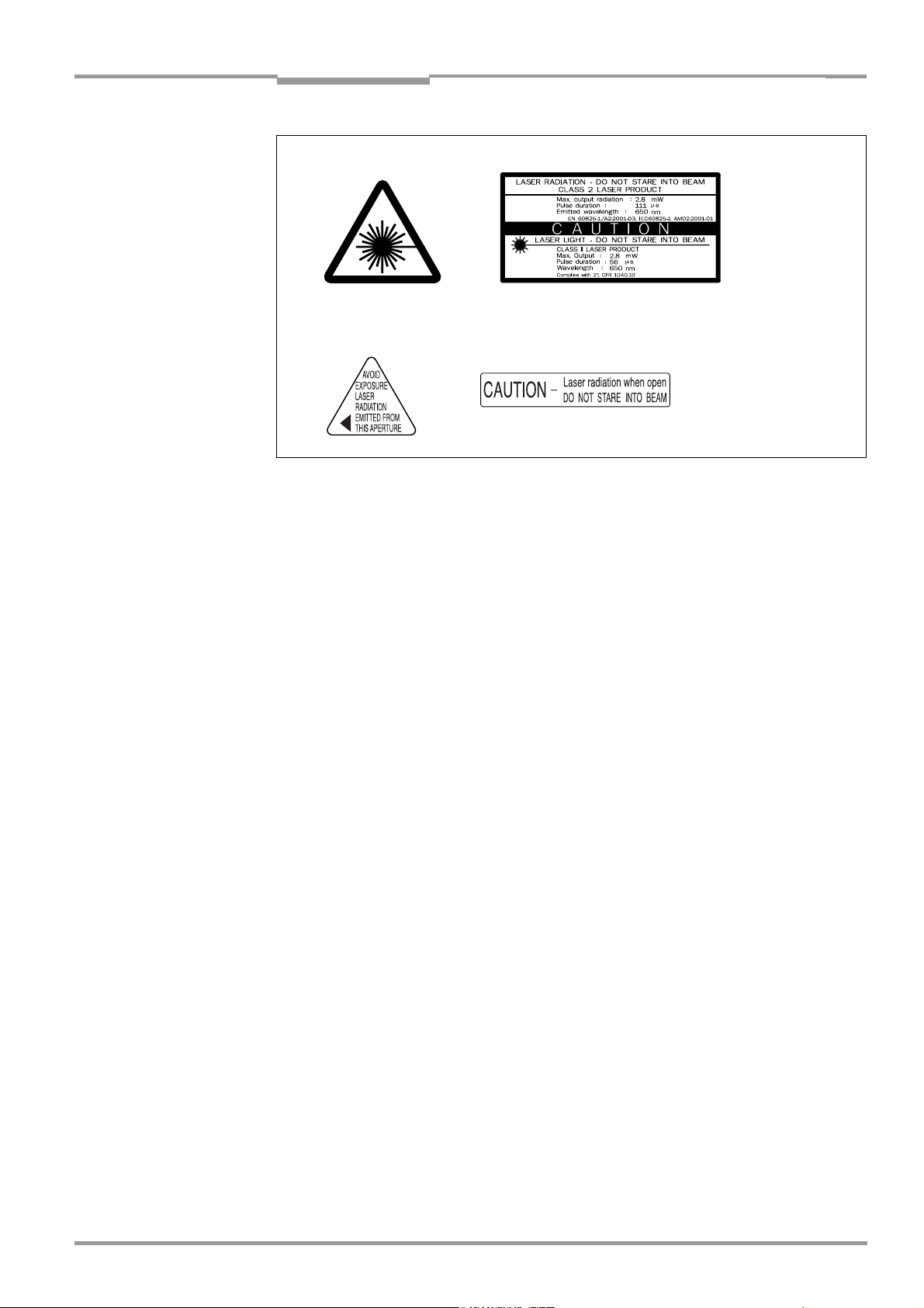
Operating Instructions Chapter 2
CLV 490 Bar Code Scanner
Safety information
black-yellow signed on
black-silver signed on device:
Fig. 2-1: Laser warning labels on the CLV
Note A set of laser warnings in German/US English and French/US English is included in the
delivery scope. The GB English/US English warnings can be pasted over with these if
necessary.
If the CLV is installed in a machine/panel with the result that the laser warning labels
are no longer visible, additional warnings (not included in the scope of delivery) must
be provided on the machine beside the emergence aperture of the laser beam.
Internal protective circuits
The CLV is equipped with monitoring circuits that deactivate the laser diode in the event of
a malfunction. No maintenance required to keep this product in compliance with laser
class II.
Activation and deactivation of the laser diode is controlled by the reading pulse (trigger
source).
A timer (laser timeout) automatically deactivates the laser diode in Reading mode ("Sensor
input" and "Serial interface" trigger mode) if the reading interval has not ended after
10 minutes (default setting). However, it does not end the reading interval. In this case, the
CLV outputs the message:
"Laser safety timeout"
on the terminal interface. The reading interval must be terminated by resetting the trigger
signal. The laser diode is activated again by the next reading trigger.
The laser timeout can be set in the range of 1 min to 25 h or deactivated (see Table 6-23,
Page 6-37).
In the "Percentage Evaluation" mode, "Adjusting" mode and "Show CP-limits" mode as
well as in the pulse mode "Free-running", in reading mode, the laser diode is constantly
activated. In the pulse mode "Object Polling" the laser diode is activated due to the
parameterized search/pause ratio. In the "Background Analysis" function the laser didoe is constantly pulsed.
Note In the Reading mode, the CLV carries out a distance measurement referencing at regular
intervals. During referencing, it turns the laser diode on for a maximum of 10 seconds.
8 009 993/O824/20-12-2004 © SICK AG · Division Auto Ident · Germany · All rights reserved 2-3
Page 22

Chapter 2 Operating Instructions
Safety information
CLV 490 Bar Code Scanner
2.4 Quick stop and quick restart
2.4.1 Stopping the CLV
¾ Switch off the power supply or remove the cables of the CLV from the connection
module.
This can result in loss of the following (at the most):
• The application-specific parameter set, if it was stored temporarily in the CLV
• The last reading result
• Daily operating data
(operating hours counter, number of reading intervals, Good Read count, No Read
count, maximum duration trigger, minimum duration trigger, matchcode 1 count, matchcode 2 count, no match count)
2.4.2 Restarting the CLV
¾ Switch on the power supply or reattach the cables of the CLV to the connection
module.
The CLV resumes operation with the parameter set that was last stored permanently
and reset the daily operating data.
2.5 Environmental information
The CLV is designed to cause minimum impact on the environment. It does not contain any
silicone-based materials on the housing surface and, therefore, does not represent any
problems for paint sprayers in paint shops, for example.
2.5.1 Power requirements
The power requirements depend on the variants:
• The line scanner has a typical power consumption of 11 W and max. 16 W
• The line scanner with oscillating mirror has a typical power consumption of 13 W and
max. 18 W
• The line scanner equipped with an integrated heater has a typical power consumption
of 75 W and max. 90 W
• The line scanner with oscillating mirror equipped with an integrated heater has a typical
power consumption of 75 W and max. 100 W
The values are given for devices with disconnected switching outputs.
2.5.2 Disposal after removal from service
Always dispose irreparable devices in a manner that is not harmful to the environment and
in accordance with the applicable national waste disposal regulations. The CLV can be
separated into recyclable secondary raw materials and special-category waste (electronic
scrap).
See also Chapter 7.3 Disposal, Page 7-2.
SICK AG currently does not accept delivery of unusable or irreparable devices.
2-4 © SICK AG · Division Auto Ident · Germany · All rights reserved 8 009 993/O824/20-12-2004
Page 23
Operating Instructions Chapter 3
CLV 490 Bar Code Scanner
Product description
3 Product description
3.1 Design
3.1.1 Scope of delivery
The CLV is supplied with the following in the packing:
• An information sheet (note on device) with terminal diagram and Quick Start instructions
• An additional set of Class 2 laser warning labels (self-adhesive) in German/US English
and French/US English
Depending on the number of devices ordered, one or more copies of the following:
• CD-ROM (no. 2 029 112) with
– "CLV-Setup" program for Windows
(HTML files)
– "CLV Connect" PC software (HTML files showing terminal diagrams)
– CLV 490 Operating Instructions in English and German as PDF edition as well as
additional publications (connections module, other SICK bar code scanners)
– freely available "Acrobat Reader" PC software for reading PDF files
Note The latest versions of all the current publications/programs on the CD-ROM can also be
downloaded from www.sick.com.
TM
and the "CLV-Setup Help" online help system
Depending on the number of copies ordered, the delivery includes (optional):
• CLV 490 Operating Instructions in English and/or German (printed edition)
Chapter 10.13 Accessories, Page 10-75 contains an overview of the available mounting
accessories, (bus) connection modules, external parameter memories, cables, connectors,
and incremental encoder as well as sensors for generating the reading pulse.
3.1.2 Variants
The CLV is currently available in the following variants:
Type (red light) Part. no. Scanning method Resolution
CLV 490-2010 1 019 311 Line scanner From 0.2 mm (7.9 mil) End No
CLV 490-3010 1 019 313 Line scanner with oscillating mirror From 0.2 mm (7.9 mil) Side No
CLV 490-2011 1 019 312 Line scanner From 0.2 mm (7.9 mil) End Yes
CLV 490-3011 1 019 314 Line scanner with oscillating mirror From 0.2 mm (7.9 mil) Side Yes
High density
CLV 490-0010 1 016 958 Line scanner From 0.3 mm (11.8 mil) End No
CLV 490-1010 1 016 959 Line scanner with oscillating mirror From 0.3 mm (11.8 mil) Side Yo
CLV 490-0011 1 016 960 Line scanner From 0,3 mm (11.8 mil) End Yes
CLV 490-1011 1 016 961 Line scanner with oscillating mirror From 0.3 mm (11.8 mil) Side Yes
Standard
CLV 490-6010 1 018 872 Line scanner From 0.4 mm (15.7 mil) End No
CLV 490-7010 1 019 094 Line scanner with oscillating mirror From 0.4 mm (15.7 mil) Side No
CLV 490-6011 1 019 095 Line scanner From 0.4 mm (15.7 mil) End Yes
CLV 490-7011 1 019 096 Line scanner with oscillating mirror From 0.4 mm (15.7 mil) Side Yes
Low density
Reading window
Heater
Table 3-1: CLV variants
8 009 993/O824/20-12-2004 © SICK AG · Division Auto Ident · Germany · All rights reserved 3-1
Page 24

Chapter 3 Operating Instructions
Product description
CLV 490 Bar Code Scanner
3.1.3 System requirements for stand-alone configuration
CLV without heater The following are required to start up and operate the CLV 490 without heater:
1. A SICK Connection Module to provide the power supply of the CLV (18 to 30 V DC) and
connect the data and function interfaces. Available types:
– CDB 420-001 (no. 1 023 885) for 10 to 30 V DC, enclosure rating max. IP 65
– CDB 420-101 (no. 1 024 305) for 10 to 30 V DC, enclosure rating max. IP 65
– CDM 490-0001 (no. 1 025 363) for 10 to 30 V DC, enclosure rating max. IP 65
– or –
Alternatively, a non-SICK Power pack with a voltage output of 18 to 30 V DC (functional
extra-low voltage pursuant to IEC 364-4-41) and a minimum power output of 20 W.
Cable no. 2 020 264 (3 m (9.84 ft)) with 15-pin D Sub HD connector and one open
end for connecting the CLV to the non-SICK Power pack (supply voltage).
2. The following operating voltages/power output values:
– CDB 420-001: 18 to 30 V DC (to IEC 364-4-41), min. 20 W
– CDM 490-0001: 18 to 30 V DC (to IEC 364-4-41), min. 40 W,
when using the CMP 490 Power Supply Module: 100 to 250 V AC, 50 to 60 Hz
– If the following modules are additionally built-in in the CDB 420:
CMC 400 (Conenction Module Cloning): 18 to 30 V DC, additionally 0.5 W
– If the following modules are additionally built-in in the CDM 490:
CMC 400 (Connection Module Cloning): 18 to 30 V DC, additionally 0.5 W
CMD 400 (Connection Module Display): 18 to 30 V DC, additionally 1 W
CMF 400 (Connection Module Fieldbus): 18 to 30 V DC, additionally 2 W
3. Fitting cables see Chapter 5.2.2 Prefabricated cables (overview), Page 5-2.
4. With external clock pulse (start/stop) supply via the "Sensor" switching input: a suitable
reading pulse sensor for signaling an object with a bar code, e. g. a photoelectric reflex
switch.
5. With extended external clock pulse (stop) via the "IN 4" switching input: a suitable read-
ing pulse sensor for signaling the end of an object, e. g. a photoelectric reflex switch.
6. With object distance detection via the "IN 0" to "IN 4" switching inputs: suitable sensors
for multi-stage dynamic focus control, e. g. photoelectric reflex switches.
7. With internal object tracking (to assign bar codes to objects if there are only small dis-
tances between the objects in conveying direction): a suitable incremental encoder,
e. g. no. 2 022 714.
8. To separate bar codes with the same name (same code type, identical data content)
using the "Compare Code Position" function: a suitable incremental encoder (s. above).
9. A higher-level computer (host) with a data interface of type RS 422/485 or RS 232.
10. A PC (min. 80486, 66 MHz, 16 MB RAM, CD drive, a serial port (COM x), mouse
(recommended)) with Windows 95
Windows XP
TM
.
TM
/98TM, Windows NTTM, Windows 2000TM or
11. A 3-core RS 232 data cable (null modem cable) with two 9-pin D Sub sockets for con-
necting the PC to the terminal interface of the CLV in the connection module, e. g.
no. 2 014 054. Pin 2 (RxD) and Pin 3 (TxD) are crossed.
12. An HTML browser, e. g. Internet Explorer
TM
, for using the online help system CLV-Setup
Help.
13. To connect the CLV to Profibus DP, to Device Net or to Ethernet TCP/IP: the appropriate
CMF 400 Connection Module Fieldbus for building-in in the CDM 490 Connection Module.
3-2 © SICK AG · Division Auto Ident · Germany · All rights reserved 8 009 993/O824/20-12-2004
Page 25

Operating Instructions Chapter 3
CLV 490 Bar Code Scanner
Product description
14. For connection of the CLV to the CAN Scanner Network: the Operating Instructions
“Application of the CAN interface“ (no. 8 009 180, English edition).
CLV with heater The following are required to start up and operate the CLV 490 with heater:
1. A SICK Connection Module to provide the power supply for the CLV (24 V DC +20 %/
–10 %) and connect the data and function interfaces. Available types:
– CDM 490-0001 (no. 1 025 363) for 10 to 30 V DC, enclosure rating max. IP 65
– or –
Alternatively, a non-SICK Power pack with a voltage output of 24 V DC +20 %/–10 %
(functional extra-low voltage pursuant to IEC 364-4-41) and a minimum power output
of 100 W.
Cable no. 2 020 264 (3 m (9.84 ft)) with 15-pin D Sub HD connector and one open
end for connecting the CLV to the non-SICK Power pack (supply voltage).
2. The following operating voltages/power output values:
– CDM 490-0001: 24 V DC +20 %/–10 % (pursuant to IEC 364-4-41), min. 100 W
Note The CMP 490 Power Supply Module (output max. 25 W) is not suitable to provide the power
supply for the CLV with heater.
3. See pos. 3 under CLV without heater
3.1.4 Product features and functions (overview)
High-performance laser scanner:
• Line scanner (front-end reading window)
• Scanner variant with oscillating mirror (side reading window)
• Resolution variants: standard density, high density, low density
• Dynamic focus (autofocus with distance measurement)
• Alternatively dynamic focus control with external or internal trigger
• Reading range 500 to 2,100 mm (19.7 to 82.7 in) (line scanner, standard density)
• Resolution 0.25 to 1.0 mm (9.8 to 39.4 mil) (standard density)
• Scanning/decoding frequency 600 to 1,200 Hz
• Reading range can strongly be limited (3-dimensional reading space)
Safety and user-friendly features:
• Robust, compact metal housing, max. IP 65, CE certification
• Laser class 2, laser diode switches off if reading interval is active for too long and if the
output power is exceeded
• Automatic self-test on startup. Can also be triggered at any time
• Diagnosis tools for installing and monitoring the system
• Parameterized output of reading diagnosis data in reading mode
• Operating data query, and error messages
• Test string function for signaling readiness for operation
• Future proof thanks to firmware update via serial interface (flash PROM)
• Low power consumption, other voltage range
Easy operation/configuration:
• With "CLV-Setup" PC software for Windows
• Alternatively with simple command strings, also for use with special devices
8 009 993/O824/20-12-2004 © SICK AG · Division Auto Ident · Germany · All rights reserved 3-3
Page 26

Chapter 3 Operating Instructions
Product description
CLV 490 Bar Code Scanner
• Four status LEDs
• External parameter memory optional) simplifies device replacement
Operating modes:
• Reading mode
• Percentage evaluation - for assessing the quality of the reads
• Special functions for system installation
Bar code evaluation:
• All standard bar code types
• Max. 50 codes per reading pulse, max. 12 per scan
• Code comparison (max. 5 matchcodes), can also be used as filter or sort criterion for
the reading result
• Sort sequences: code position, FIFO, LIFO, code length list, matchcodes
Reading pulse (start/stop mode):
• External reading pulse, via switching input(s) or serial interface
• Timer (scanner with oscillating mirror: also oscillating extrema)
• Free running
• Object polling for on object per reading interval
Object Tracking (Tracking mode):
• Internal object tracking for max. 10 objetcs per reading interval
• Extended object tracking (20 objetcs) in combination with OTS 400 Object Tracking
System
Electrical interfaces:
• Serial host interface (RS 422/485 or RS 232) with variable transfer rate and telegram
structure
• Serial terminal interface (RS 232) as auxiliary data interface with special diagnosis and
statistics functions
• CAN interface for integration in the SICK CAN Scanner Network or a CANopen network,
and for OTS operation
• 6 switching inputs for external reading pulse, focus control, encoder increment and spe-
cial function (teach-in)
• 4 switching outputs for signaling defined events in reading mode
Connections:
• All interfaces are connected via two 15-pin D Sub HD connections on the housing
• CDB 420 or CDM 490 Connection Module for connection to host and for integration in
SICK CAN Scanner Network
• CMF 400 Connection Module Fieldbus in the CDM 490 for connection to field bus sys-
tems
Additional functions:
• Version with integrated heater (max. –35 °C (–31 °F))
• External parameter memory in connector cover (optional)
3-4 © SICK AG · Division Auto Ident · Germany · All rights reserved 8 009 993/O824/20-12-2004
Page 27
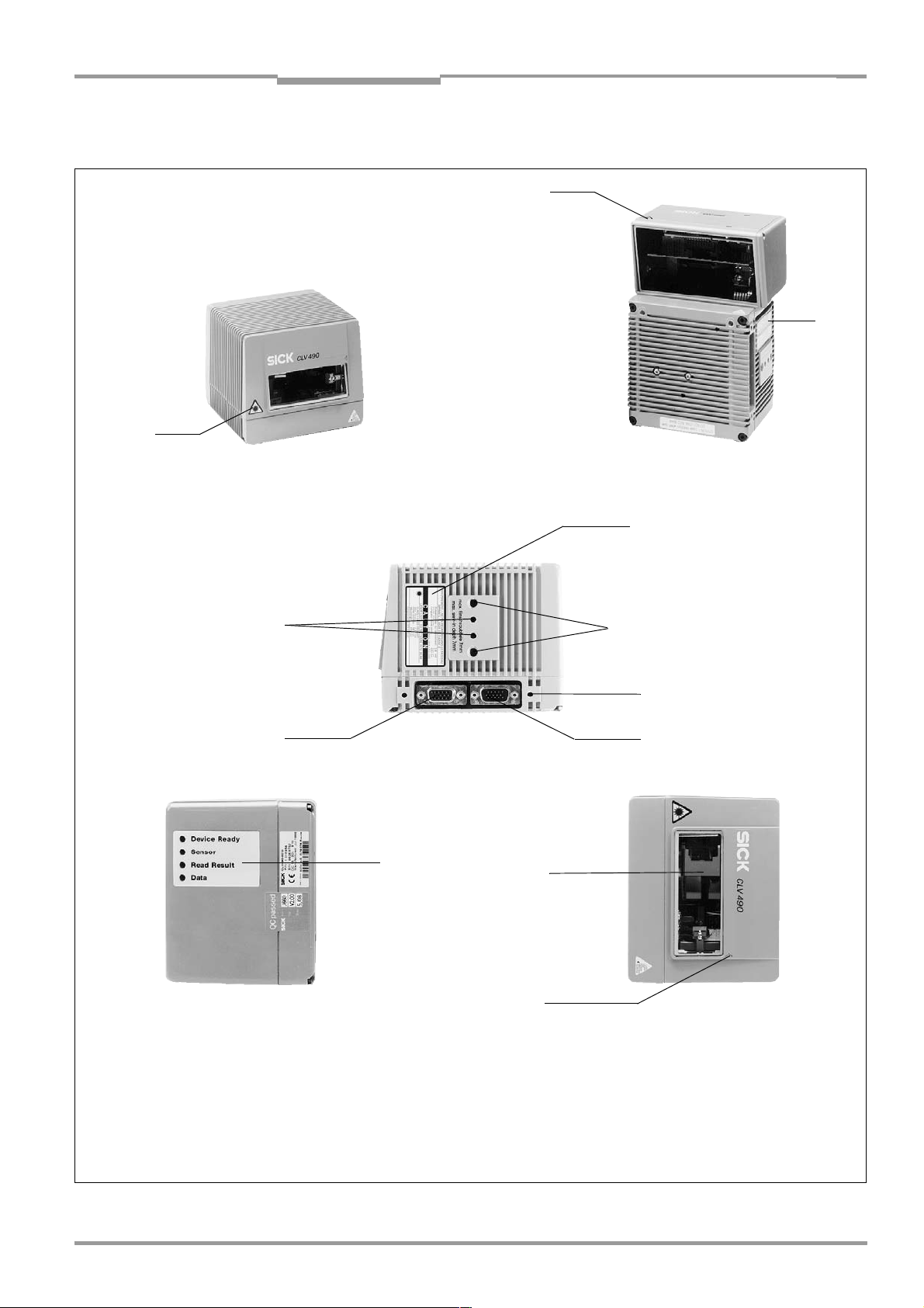
Operating Instructions Chapter 3
CLV 490 Bar Code Scanner
Product description
3.1.5 Design
➋
➋
➋
Line scanner
(front-end reading window)
➊
➏
Line scanner with oscillating mirror
(side reading window)
➋
➌
➍
➎
➐
➑
➒
Legend
➊ Drilled hole, Ø 3.6 mm (.14 in),
6 mm (.24 in) deep
➋ Laser warning labels
➌ Blind hole thread M6, 7 mm (.28 in)
deep, for securing the device
Fig. 3-1: Design of the CLV 490
8 009 993/O824/20-12-2004 © SICK AG · Division Auto Ident · Germany · All rights reserved 3-5
➍ Blind hole thread M4, 10 mm
(.39 in) deep, for the connector
cover
➎ "Host/Term" connector
15-pin D Sub HD plug
➏ "I/O" connector,
15-pin D Sub HD socket
➐ LEDs (status indicators)
➑ Reading window
➒ Mark for count direction of the code
position (deflection direction of the
laser beam)
Page 28

Chapter 3 Operating Instructions
Product description
CLV 490 Bar Code Scanner
3.2 Method of operation
The CLV first scans the bar code with a scan line and then decodes it. In stand-alone configuration, the data is forwarded via the serial host interface (main data interface) to a host/
PC for further processing, or via the CAN interface to the OTS 400 Omni Tracking System.
An overview of the CLV functions is provided in Fig. 3-2.
CLV 490
PC
Operation
Parameterization,
Photoelectric
switch
Reading pulse
*)
Signal
Focal control
Trigger One-Shot
Conveyer increment
End of reading
interval
etc.
HOST
Further processing
of the reading result
CAN bus
Status display
e. g. Device Ready
e. g. Good Read
e. g. No Read
e. g. Match 1
*) if required
Fig. 3-2: Block diagram: CLV functions
The CLV is equipped with two decoders:
• The SMART decoder (SICK Modular Advanced Recognition Technology) for decoding
bar codes with small code height, bar codes that are dirty or damaged, as well as bar
codes that are tilted excessively (azimuth angle)
• The tried-and-tested standard decoder of the CLV series
The CLV derives useful diagnosis data from the reading process and can transfer it to also
the host. It also records operating data that can be interrogated at any time. The quality of
the read can be checked in percentage evaluation mode.
To start the reading process when an object is located in the reading field, the CLV requires
a suitable trigger. This opens an internal time window ("reading interval") in the CLV. In the
default configuration, this trigger is supplied by an external reading pulse sensor. Alternative
trigger sources include Free-running mode or a command via the host interface (for more
complex applications: object polling or OTS trigger).
The current operating status is indicated by four LEDs.
If the trigger is supplied externally, the "Sensor" switching input instructs the CLV to start the
reading process. The five "IN 0" to "IN 4" switching inputs switch the focus position in
response to certain events, as an alternative to the autofocus function. The "IN 3" and
"IN 4” inputs can also be assigned special functions. The four "Result 1" to "Result 4"
switching outputs can be assigned to different functions for displaying the result status and
also control external devices, such as a PLC.
The CLV is operated and configured via the serial terminal interface (auxiliary interface) using
the "CLV-Setup" software or via the host interface/terminal interface using command
strings.
3-6 © SICK AG · Division Auto Ident · Germany · All rights reserved 8 009 993/O824/20-12-2004
Page 29
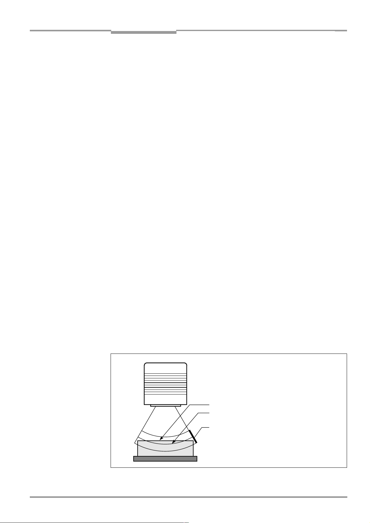
Operating Instructions Chapter 3
CLV 490 Bar Code Scanner
Product description
System and error messages help you to configure the device and to locate the source of
errors during startup and reading mode.
3.2.1 Autofocus function
The autofocus function enables the CLV to detect the distance of an object during the reading process, without the need for external sensors, and then adjusts the focus position automatically to the reading plane of the bar code. In order to do so, the CLV measures the
object distance each time in its reading field in front of the reading window and internally creates a distance profile. Following this, it positions the focus on the object.
3 operating modes are provided for various applications:
• Minimum distance: the CLV focuses on the minimum distance in the distance profile
and ignores the background in the reading field. Application: with unobstructed view of
the object without any surrounding objects protruding into the reading plane.
One object with bar code(s) only is inside the reading field during one reading pulse.
• Differential background: the distance profile of the reading field background is pro-
grammed (teach-in) in the CLV without any objects present. During the reading process,
the CLV then focuses on the object which it recognizes by comparing the actual distance profile to the distance profile of the background. Application: with unobstructed
view of the object restricted by other objects that protrude constantly into the reading
plane.
One object with barcode(s) only is inside the reading field during one reading pulse.
• Differential background and tracking: if several objects with different distances to the
CLV are positioned in the reading field at the same time (distance conflict), the CLV focuses on the object that is nearest to but has not exceed its internal focus switchover
point. Application: in OTS operation (applications with internal tracking or tracking by the
OTC 400 Omni Tracking Controller).
The distance profile of the background can also be displayed in the "CLV-Setup" program.
The autofocus range is defined by the aperture angle, the autofocus space, and (in the case
of line scanners with oscillating mirror) also by the angle of deflection. The park setting of
the focus position, from which the device focuses for each read, can be specified in addition
to a time and/or position-related delay (timeout or hysteresis). If necessary, an offset can
be defined for the focus position to be set by the measurement. The depth of field, which
radiates in the direction of the scan lines and is caused by the V-principle of the beam deflection, is optimized as a result (Fig. 3-3).
Measured distance
Optimum focus position:
measured distance plus offset for maximum
Depth of field (DOF)
Fig. 3-3: Optimization of the depth of field for the object
8 009 993/O824/20-12-2004 © SICK AG · Division Auto Ident · Germany · All rights reserved 3-7
Page 30
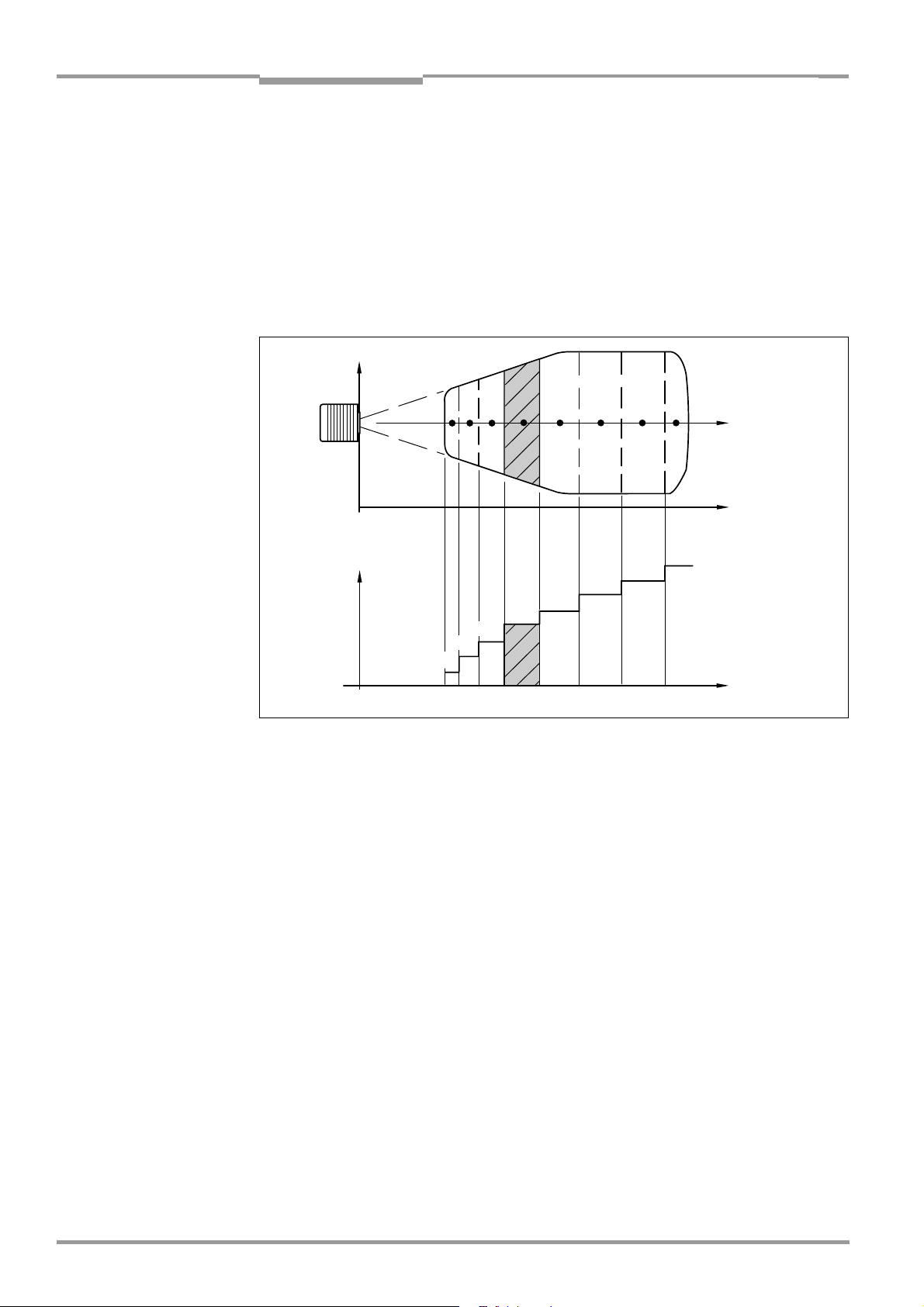
Chapter 3 Operating Instructions
Product description
CLV 490 Bar Code Scanner
In autofocus mode and in combination with the OTS 400 Omni Tracking System the CLV can
also use the object height information from the OTS 400 or any other CLV transmitted via
the CAN bus.
3.2.2 Event-controlled dynamic focus control
As an alternative to the autofocus function, the CLV can switch its focus position in response
to certain events and thus dynamically cover a large reading range. A maximum of eight
reading ranges can be defined as distance configurations for this purpose and approached
consecutively in reading mode (see Fig. 3-4).
Reading
field height
123 5 8
Focus
position
DC 3
DC 2
DC 1
DC = Distance Configuration
Fig. 3-4: Dynamic focus control: classification of the reading range in distance configurations
4
DC 5
DC 4
6 7
DC 6
Focus position
Reading distance
DC 8
DC 7
Reading distance
The switch over takes place in response to changes in the object distance (with reads from
above: object height detection). The trigger source for the switchover can be:
• A signal combination at the "IN 0" to "IN 4" switching inputs, a command on the host
interface/terminal interface or the integrated timer (e. g. for search mode). Additional in
the case of the line scanner with oscillating mirror also the oscillating mirror reversal
points. The distance configurations are assigned to the switchover sequence by means
of a programmable assignment table.
• In combination with the OTS 400 Omni Tracking System:
Alternatively the object height information from the OTS 400 or any other CLV via the
CAN bus.
The distance measurement of the autofocus function can be additionally used to define the
distance configurations.
3.2.3 Reading modes in stand-alone configuration
Start/stop mode
During the reading process, only one object is located in the reading field in start/stop
mode, i. e. all read bar codes can be clearly assigned to the object. As default, two reading
pulse sensors at the beginning and at the end of the reading field control the starting and
stopping of the reading process (Fig. 3-5). The size of the reading field is determined by the
distance between the two sensors. Alternatively, the reading process can be controlled with
3-8 © SICK AG · Division Auto Ident · Germany · All rights reserved 8 009 993/O824/20-12-2004
Page 31
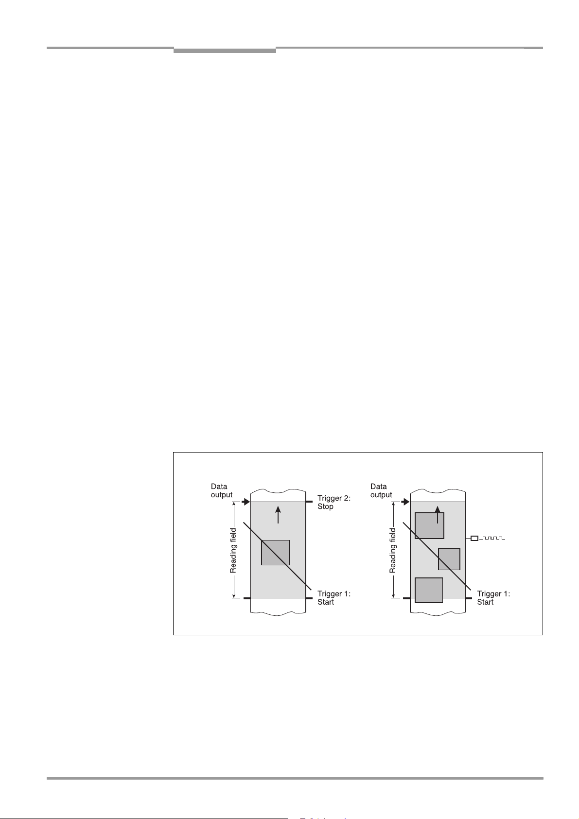
Operating Instructions Chapter 3
CLV 490 Bar Code Scanner
Product description
command strings via the data interface or can be left free running. The CLV either outputs
the reading result at the end of the reading pulse (the back edge of the object has left the
end of reading field) or already during the reading pulse as a result of predefined (parametrized) conditions. To separate bar codes of the same type with identical contents, an incremental encoder must be connected to the CLV.
In object polling mode, the CLV automatically detects the beginning and the end of the object located in the reading field without any help of external sensors. The minimum temporal
distance between two consecutive objetcs must not fall below 70 ms when the objects are
moved on the conveyor belt.
Tracking mode
During the reading process, max. 10 objects can simultaneously be located in the reading
field (following each other) in internal tracking mode, i. e. the CLV must be able to clearly
assign the bar codes to the objects (Fig. 3-5). As default, a reading pulse sensor at the beginning of the reading field controls the starting of the reading process. The end of the reading field is determined by the parametrized object release point in the CLV. In this way, the
size of the reading field is clearly determined.
In order to track the transport of the objects in the reading field, a regularly-timed pulse is
required. This is generated by an external incremental encoder which regularly supplies a
pulse at least every 10 mm (0.39 in) of movement in conveying direction. As a result, the
the distance between the reading pulse sensor and the object release point is clearly timemapped in the CLV. Fluctuations when approaching the conveyor or decreases in speed due
to heavy load with numerous conveyor obejcts are also recorded. An internal clock in the
CLV also allows operation at a constant conveyor speed. A gap of at least 50 mm (1.97 in)
is necessary for the clear separation of consecutive objects. The reading result for an object
is output after the back edge of the object passes the object release point. Alternatively, the
reading process can be started with a command strings via the data interface.
Start/stop mode
Fig. 3-5: Reading modes of the CLV in stand-alone configuration
Tracking mode
3.2.4 Scan procedure variants
Line scanner (standard device)
Generates a scan line; due to the V-principle of the beam generation, the reading field height
(the useful length of the scan line for evaluation purposes) is dependent on the reading
distance.
8 009 993/O824/20-12-2004 © SICK AG · Division Auto Ident · Germany · All rights reserved 3-9
Page 32

Chapter 3 Operating Instructions
Product description
CLV 490 Bar Code Scanner
Line scanner with oscillating mirror
The oscillating mirror also deflects the scan line perpendicularly to the scan direction at both
sides around the neutral position with a low oscillating frequency. As a result, the CLV can
also scan larger areas for bar codes. Due to the V-principle of beam generation, the reading
field height is dependent on the reading distance.
In addition to parking (fixed position) and simple deflection with maximum amplitude, optimized oscillating mirror functions are also available:
• Oscillating with variable deflection amplitude per distance configuration
• One-Shot: one-off, defined deflection per reading pulse (forward and return phase)
3.2.5 Additional components
Heater
The CLV can be permanently equipped with a heater for applications involving temperatures
up to max. –35 °C (–31 °F) (e. g. in a freezer).
The design, technical data, and power-up behavior of the CLV are described in Chapter 10.4
Optional heating, Page 10-40.
External parameter memory in connector cover
The external parameter memory is located in a connector cover which, when mounted,
covers the two electrical terminals on the CLV (IP 65). The parameter memory saves you
time when a CLV is replaced locally by providing a copy of the current parameter set. In other
words, you do not have to configure the new device.
For information on applications and operating procedures, see Chapter 10.3 Installing and
operating the external parameter memory (connector cover), Page 10-34.
3.3 Indicators and control elements
3.3.1 Control elements
The CLV is operated and configured via the terminal interface (auxiliary interface) using the
"CLV-Setup" program or using command strings sent via the host interface/terminal interface. A variety of parameter options allow you to adapt the device to a wide range of applications.
The following can be defined:
• The configuration of the code types
• The read, evaluation, and output properties
• The communication parameters of the host interface/CAN interface
• The structure of the data output string for "Good Read" and "No Read" on the host in-
terface/CAN interface
• The function of the terminal interface
Chapter 10.6 Installing and operating the "CLV-Setup" program, Page 10-43 describes the
procedure for installing the "CLV-Setup" program and explains how to use it. The parameterization (configuration) procedure is explained in Chapter 6.4 Configuring (parameterizati-
on) the CLV, Page 6-5.
3-10 © SICK AG · Division Auto Ident · Germany · All rights reserved 8 009 993/O824/20-12-2004
Page 33
Operating Instructions Chapter 3
Product description
CLV 490 Bar Code Scanner
3.3.2 Function of the LEDs
Four LEDs indicate the operating status, activity of the laser diode, reading result status, and
data transfer on the host interface. The LEDs are located on the rear of the device (Fig. 3-6).
If the optional external parameter memory is connected, the LEDs also indicate whether the
memory was successfully accessed.
Device Ready
Sensor
Read Result
Data
Fig. 3-6: LEDs
The meaning of the LEDs in the various operating modes/functions is shown in Table 3-2
and Table 3-3.
CLV without external parameter memory:
Operating mode LED Display Function
Start Device Ready Green • Lights up after power-up if the self-test was successful
Subsequent behavior depends on selected start option:
Start option: START WITH EXTERNAL PARAMETERS (default)
• Lights up constantly (CLV has loaded internal parameter set)
Start option: START WITH INTERNAL PARAMETERS
• Lights up constantly (CLV has loaded internal parameter set)
Start option: START WITH COPY INTERN -> EXTERN
• Blinks constantly together with the "Read Result" LED
(CLV has loaded internal parameter set)
Read Result Green
Start option: START WITH COPY INTERN -> EXTERN
• Blinks constantly together with the "Device Ready" LED
Reading mode Device Ready Green • Lights up constantly
• Extinguishes with new operating mode/function
Sensor Green • Lights up if reading diode is active
(The laser diode is activated/deactivated by reading pulse)
• Lights up constantly in Free-running mode, since laser diode is always active
Read Result Green LED is linked to the "Result 2" switching output and indicates the selected result
status for the defined pulse duration of the output.
• Lights up after a successful read (default: Good Read)
• Lights up if the match code comparison is active, the bar code read matches the
specified match code(s) and the corresponding result status output is selected
for the "Result 2" output
Data Yellow • Flickers when the CLV transfers data to the host on the host interface
1) Set the start option to START WITH THE INTERNAL PARAMETERS on the DEVICE CONFIGURATION tab in the "CLV-Setup" program. Download to CLV!
1)
1)
Table 3-2: Meaning of LEDs: CLV without external parameter memory
8 009 993/O824/20-12-2004 © SICK AG · Division Auto Ident · Germany · All rights reserved 3-11
Page 34
Chapter 3 Operating Instructions
Product description
CLV 490 Bar Code Scanner
Operating mode LED Display Function
Percentage Sensor Green • Lights up constantly, as Free-running mode is active
evaluation Read Result Green Behavior depends on the reading quality:
• Extinguishes if reading rate < 30 %
• Blinks twice a second if reading rate 30 % to 70 %
• Blinks five times a second if reading rate 70 % to 90 %
• Lights up constantly if reading rate > 90 %
Adjusting mode Sensor Green • Lights up constantly, as Free-running mode is active
Show CP-limits Sensor Green • Blinks bright/dark alternately, in the frequency with which the scan line is (partially)
masked out
1) Set the start option to START WITH THE INTERNAL PARAMETERS on the DEVICE CONFIGURATION tab in the "CLV-Setup" program. Download to CLV!
Table 3-2: Meaning of LEDs: CLV without external parameter memory (contd.)
CLV with external parameter memory connected
a) External parameter memory in connector cover
Operating mode LED Display Function
Start Device Ready Green • Lights up after power-up if the self-test was successful
Subsequent behavior depends on selected start option:
Start option: S
• Blinks for approx. 10 s before lighting up constantly
(CLV has loaded the parameter set from the external parameter
memory and starts reading mode straight away)
• Blinks for approx. 10 s together with the "Read Result" LED, then lights up
constantly.
(CLV has loaded the parameter set from the external parameter memory with
tolerated errors
• Lights up constantly
(CLV could not find an external parameter memory and loads the internal parameter set instead)
• Blinks constantly together with the "Read Result" LED
(The external parameter memory contains the parameter set for a different CLV
type or is corrupt.
CLV has loaded the internal parameter set. It starts Reading mode but does not
output data over the host interface.)
TART WITH EXTERNAL PARAMETERS (default)
1)
and starts reading mode straight away)
2)
Start option: START WITH INTERNAL PARAMETERS
• Lights up constantly (CLV has loaded internal parameter set)
Start option: START WITH COPY INTERN -> EXTERN
• Blinks alternately with the "Read Result" LED for approx. 10 s before lighting
up constantly
(CLV has successfully copied the internal parameter set to the external memory
and has reset the start option to START WITH EXTERNAL PARAMETERS).
CLV has loaded the internal parameter set.
• Blinks constantly together with the "Read Result" LED
2)
(The external parameter memory is either not connected or corrupt, or the
parameter set is too large to be copied).
CLV has loaded the internal parameter set.
1) We recommend that you check the parameter set manually, e. g. by printing out the entire configuration. For troubleshooting, see also Chapter 8.3.2 LED error messages
for the external parameter memory (connector cover), Page 8-3
2) Stops blinking when you switch from Reading mode to Parameterization mode
Table 3-3: Meaning of LEDs: CLV with external parameter memory in the connector cover
3-12 © SICK AG · Division Auto Ident · Germany · All rights reserved 8 009 993/O824/20-12-2004
Page 35
Operating Instructions Chapter 3
Product description
CLV 490 Bar Code Scanner
Operating mode LED Display Function
Start
– continued –
Read Result
– continued –
Green Start option: START WITH EXTERNAL PARAMETERS (default)
• Blinks for approx. 10 s together with "Device Ready"
LED
• Blinks constantly together with the "Device Ready" LED
Start option: S
TART WITH COPY INTERN -> EXTERN
• Blinks alternately with "Device Ready" LED for approx. 10 s (see above) or
• Blinks constantly together with the "Device Ready" LED
Reading mode Device Ready Green • Lights up constantly
• Extinguishes with new operating mode/function
Sensor Green • Lights up if reading diode active
(The laser diode is activated/deactivated by the reading pulse)
• Lights up constantly in Free-running mode, since the laser diode is constantly
active
Read Result Green LED is linked to the "Result 2" output and indicates the selected result status for the
defined pulse duration of the output.
• Lights up after a successful read (Good Read)
• Lights up if the match code comparison is active, the bar code read matches the
specified match code(s) and the corresponding result output is selected for the
"Result 2" output
Data Yellow • Flickers when the CLV transmits data to the host over the host interface
Percentage Sensor Green • Lights up constantly, since Free-running mode is active
evaluation Read Result Green Behavior dependent on the reading quality:
• Extinguishes if reading rate < 30 %
• Blinks twice a second if reading rate 30 % to 70 %
• Blinks five times a second if reading rate 70 % to 90 %
• Lights up constantly if reading rate > 90 %
1)
(see above) or
2)
(see above)
2)
(see above)
Adjusting mode Sensor Green • Lights up constantly, since Free-running mode is active
Show CP-limits Sensor Green • Blinks bright/dark alternately, in the frequency with which the scan line is (partially)
masked out
1) We recommend that you check the parameter set manually, e. g. by printing out the entire configuration. For troubleshooting, see also Chapter 8.3.2 LED error messages
for the external parameter memory (connector cover), Page 8-3
2) Stops blinking when you switch from Reading mode to Parameterization mode
Table 3-3: Meaning of LEDs: CLV with external parameter memory in the connector cover (contd.)
b) External parameter memory CMC 400 in the CDB 420/CDM 490 Connection
Module
The function of the "Device Ready" and "Read Result" LEDs on the CLV when using the
CMC 400 as well as the remedy for error messages are described in the CMC 400 Oper-
ating Instructions (order no. 8 010 002, German/English).
See also Chapter 10.3.1 Function of the external parameter memory, Page 10-35.
8 009 993/O824/20-12-2004 © SICK AG · Division Auto Ident · Germany · All rights reserved 3-13
Page 36

Chapter 3 Operating Instructions
Notes:
Product description
CLV 490 Bar Code Scanner
3-14 © SICK AG · Division Auto Ident · Germany · All rights reserved 8 009 993/O824/20-12-2004
Page 37

Operating Instructions Chapter 4
CLV 490 Bar Code Scanner
Installation
4 Installation
4.1 Installation sequence
• Change the language version of the laser warning label (if necessary)
• Select the mounting location for the CLV
• Mount the CLV and align the CLV with the bar code
• Mount the CDB 420 or CDM 490 Connection Module
• Connect the CLV to the CDB 420 or CDM 490 Connection Module
• Adjust the CLV so that it is in line with the bar code
• Mount the reading pulse sensor for external triggering the reading pulse
• Option with event-controlled dynamic focus control:
mount the sensors for detecting the object distance
Note Don’t open the device. The producer warranty will be forfeited if the device is opened.
4.2 Preparations
4.2.1 Required components
• CLV Bar Code Scanner
4.2.2 Required accessories
• SICK mounting bracket for the CLV: depending on the order, angle bracket
no. 2 013 824, articulated bracket no. 2 018 435, or quick-clamping device
no. 2 016 110 with securing material for the CLV
– or –
Alternatively, if the bracket is supplied by the user
– Stable mounting device that allows the alignment of the CLV to be varied in the x and
y axes. The weight of the CLV (line scanner) is 1.5 kg (3.3 lb) and 2.2 kg (4.84 lb) as
a line scanner with oscillating mirror.
– 2 screws M6 for the CLV. The screw length depends on the wall thickness of the
bracket used. Depth of engagement in CLV max. 7 mm (0.28 in) from housing surface.
• CDB 420 or CDM 490 Connection Module (not included in the scope of supply of
the CLV)
• Reading pulse sensor for external reading pulse triggering, e. g. photoelectric reflex
switch/ photoelectric proximity switch (not included in the scope of supply of the CLV)
• Option with event-controlled dynamic focus control: sensors for detecting the object
distance, e. g. photoelectric reflex switches/photoelectric proximity switches (not
included in the scope of supply of the CLV)
• Optionally for internal tracking: an incremental encoder (not included in the scope of
supply of the CLV)
4.2.3 Required auxiliary parts
• 2 screws M6 for securing the SICK mounting bracket to the base. The screw length
depends on the wall thickness of the base.
• Set of laser warning labels (if necessary)
• Tool
8 009 993/O824/20-12-2004 © SICK AG · Division Auto Ident · Germany · All rights reserved 4-1
Page 38

Chapter 4 Operating Instructions
Installation
CLV 490 Bar Code Scanner
• Measuring tape (up to 3 m (118.2 in))
• Protractor
4.2.4 Replacing the laser warning label
If necessary, replace the GB/US laser warning label with the required language (Fig. 4-1).
The device is delivered with a set of laser warnings in:
• German/US laser warning and
• French/US laser warning
See also Chapter 2.3 General safety instructions and protection measures, Page 2-2.
Supplied laser warnings:
Fig. 4-1: Line scanner: replacing the laser warning labels
4.2.5 Selecting the mounting location
When you select the mounting location, the distance between the CLV and the host and
between the CLV and the bar code are extremely important.
Distance between the CLV and the host
The CLV can be mounted at a maximum distance of 1,200 m (3, 937 ft) from the host without a connection to the SICK network or a bus. In practice, however, the distance depends
on the physical configuration of the host interface and the data transfer rate (see
Table 5-21, Page 5-17).
Distance between the CLV and the CDB 420 or CDM 490 Connection Module
The CDB 420 or CDM 490 Connection Module should not be located further than 10 m
(32.8 ft) from the CLV, since the "CLV-Setup" program on the PC accesses the terminal interface (RS 232) of the CLV via this module.
4-2 © SICK AG · Division Auto Ident · Germany · All rights reserved 8 009 993/O824/20-12-2004
Page 39
Operating Instructions Chapter 4
CLV 490 Bar Code Scanner
Installation
4.2.6 Mounting accessories
The CLV is secured in position using the two tapped blind holes (M6) above the electrial connections. Fig. 4-2 shows the location of the threads near the line scanner.
The dimensions of the CLV housing are shown in Fig. 9-1, Page 9-3 to Fig. 9-2.
Drilled hole, ∅ 3.6 mm,
6 mm (0.24 in) deep
Fig. 4-2: Line scanner: position of the securing threads on the CLV
Blind hole thread, M6,
7 mm (0.28 in) deep
The CLV can be mounted using the SICK bracket:
• Mounting bracket, single no. 2 013 824
• Articulated bracket (2 x mounting bracket, single) no. 2 018 435
• Quick-clamping device no. 2 016 110
The brackets are designed to support a variety of mounting positions and alignments in two
planes. Fig. 4-3 shows two mounting examples.
The elongated holes in the mounting bracket no. 2 013 824 and in the articulated bracket
no. 2 018 435 allow the CLV to be adjusted with a freedom of rotation of ±15°.
Quick-clamping
device
Mounting
bracket
Fig. 4-3: Line scanner: Mounting possibilities of the CLV
The dimensions of the mounting brackets are shown in Chapter 10.14 Dimensioned draw-
ings of the accessories, Page 10-81
8 009 993/O824/20-12-2004 © SICK AG · Division Auto Ident · Germany · All rights reserved 4-3
Page 40
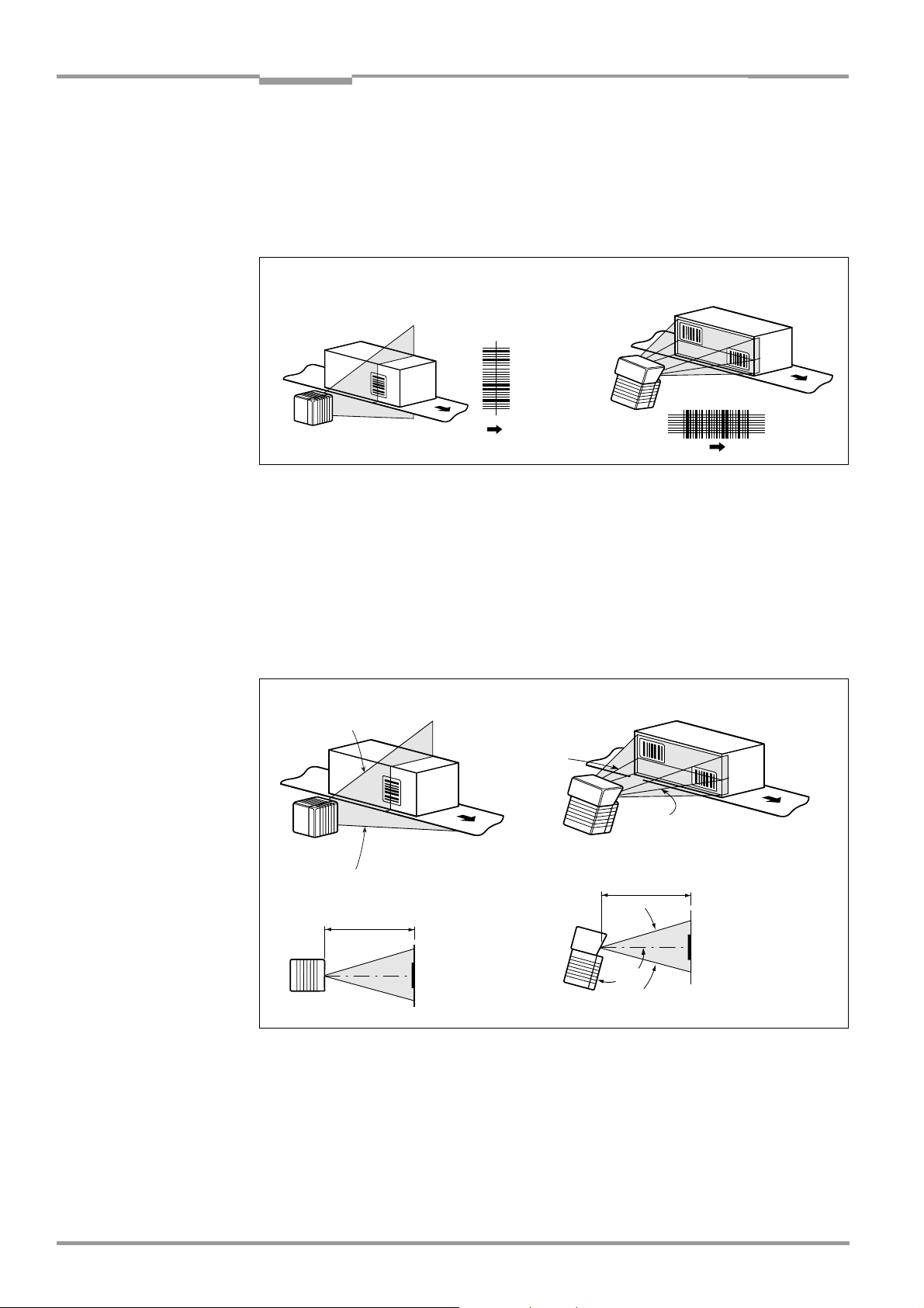
Chapter 4 Operating Instructions
Installation
CLV 490 Bar Code Scanner
4.2.7 Distance between the CLV and the bar code
Basic alignment between the CLV and the bar code
Depending on the application, the line scanner or line scanner with oscillating mirror versions
of the CLV is used. Fig. 4-4 shows how the device is aligned with the bar code on the object
for each of the two scanning methods.
Line scanner Line scanner with
oscillating mirror
Fig. 4-4: Scanning methods: alignment with bar code and conveyor direction
Reading distance from the bar code and aperture angle α
The distance between the reading window of the CLV and the bar code must not exceed
the technical limits. The height of the reading field is shown as a function of the reading
distance for various resolutions (module widths) depending on the CLV type in Chapter 10.2
Specification diagrams, Page 10-1.
Fig. 4-5 shows the definition of the reading distance "a" (radial measured) from the reading
window and of the aperture angle α each of the two scanning methods.
Line scanner Line scanner with oscillating mirror
α
Reading distance a
α
Reading distance a
105°
Fig. 4-5: Definition of the reading distance "a" and of the aperture angle α
The useful aperture angle is typically 56° for the line scanner and max. 50° for the line scanner with oscillating mirror. Due to the V-principle of beam deflection, the reading field height
(for evaluating the useful length of the scan line) depends on the readling distance.
4-4 © SICK AG · Division Auto Ident · Germany · All rights reserved 8 009 993/O824/20-12-2004
Page 41
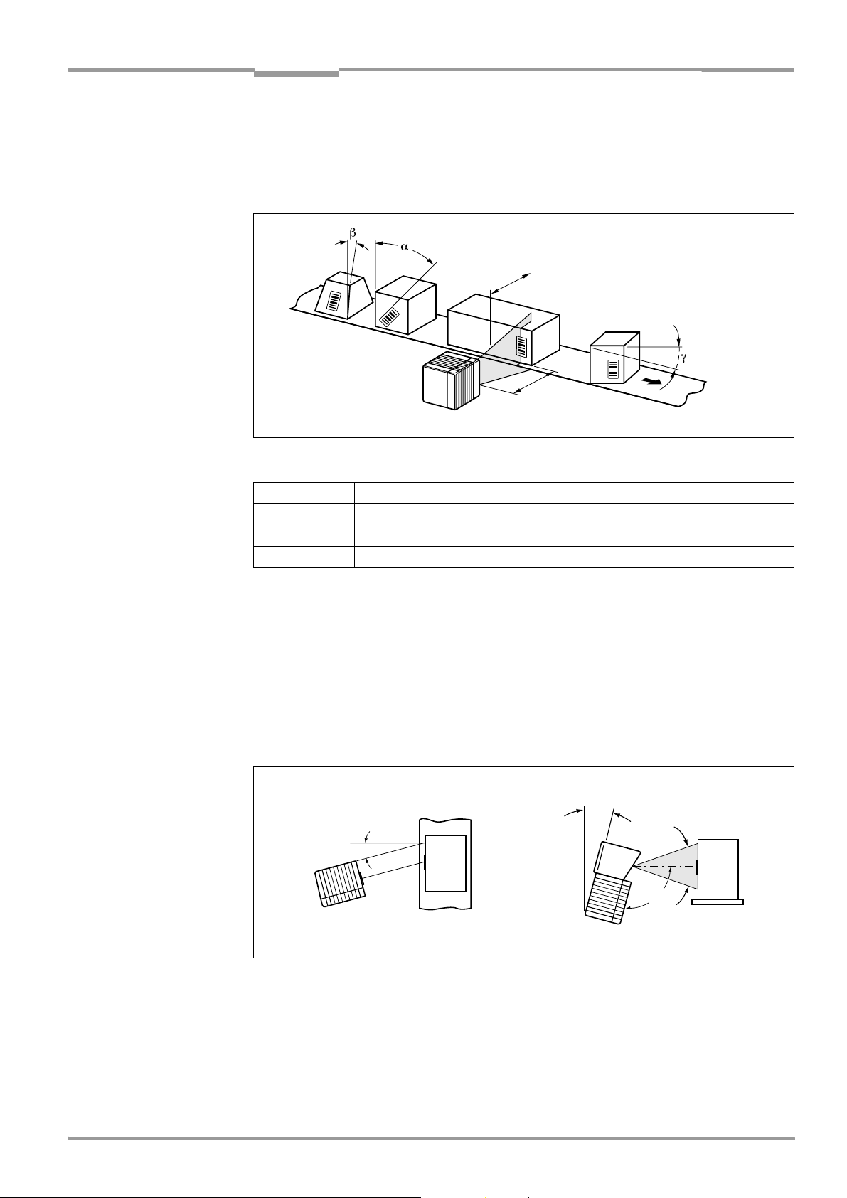
Operating Instructions Chapter 4
CLV 490 Bar Code Scanner
Installation
Angular alignment of the CLV
The alignment of the CLV is optimum when the scan line travels over the bar code lines
almost at a right angle (90°) (Fig. 4-4). All possible reading angles that can occur between
the scan line and the bar code must be taken into consideration (Fig. 4-6 and Table 4-1).
α: Azimuth angle (tilt)
β: Angle of inclination (pitch)
Reading
range
Reading
distance
CLV
Fig. 4-6: Line scanner: Reading angle between the scan line and the bar code
γ: Angle of rotation (skew)
Angle Limit value
Tilt α (azimuth) max. 45°
Pitch β max. 45°
Skew γ max. 45°
Table 4-1: Permissible reading angles between the scan line and bar code
Note If reading from the front, mount the CLV above the conveyor belt in such a way against the
conveying direction that the scan line hits the object under a skew of approx. 10°.
Avoiding surface reflection
If the light from the scan line strikes the surface of the bar code vertically, interference may
be caused by reflections when the returned light is received. To avoid surface reflection, the
CLV must be mounted in such a way that the emitted light is tilted slightly with respect to the
vertical axis (Fig. 4-7).
Line scanner Line scanner with oscillating mirror
15°
15°
105°
(Top view) (Side view)
Fig. 4-7: Avoiding surface reflections: Angle between the emitted light and the bar code (tilted
away from the vertical axis)
In the case of the line scanner with oscillating mirror, the laser beam is emitted at an angle
of 105° with respect to the housing as it passes through the neutral position (CW = 50)
while oscillating. The device can only be flush-mounted with the conveyor belt with limited
deflection ranges. Otherwise, the device must also be mounted at an angle of 15° to ensure
that the deflection ranges are symmetric.
8 009 993/O824/20-12-2004 © SICK AG · Division Auto Ident · Germany · All rights reserved 4-5
Page 42

Chapter 4 Operating Instructions
Installation
CLV 490 Bar Code Scanner
Note In oscillating mode with variable amplitude, the scan line must always sweep the neutral
position (CW = 50). This means that oscillation is not possible in the range 60 CW to 80 CW,
for example, but is possible in the range 40 CW to 80 CW.
4.2.8 Count direction of the code position CP and code angle CW
Explanation The CLV can scan and decode several bar codes with each read. In doing so, it determines
the specific local reading diagnosis data for each bar code:
• The position (CP value) of the center of the bar code within the scan line
• (Scanning method using the oscillating mirror) also the angle of deflection of the scan
line (CW value) at which the center of the bar code is recorded
Fig. 4-8 shows the count direction of the code position and code angle. In the case of the
line scanner, the count direction of the code position is marked by a small triangle above
the reading window.
By determining this data, the device can separate identical bar codes (code type, code
length, and data content identical) and assign the bar code data in the reading result to its
position on the object.
Line scanner
100
CP
0
Scanning direction
Aperture angle α (opening angle) in the scanning direction: 1° = 1.5 CP (56° = 90 CP)
Deflection angle of the scan line crosswise to the scanning direction: 1° = 2 CW (20° = 40 CW)
Fig. 4-8: Count direction of the code position CP in the scan line and of the code angle CW for the
oscillating mirror
Line scanner with
oscillating mirror
90
CW
10
0
CP
100
Tip
In the default setting, the CLV does not output the "CP" and "CW" values (line scanner with
oscillating mirror only) in the reading result on the host interface. If this is required to
evaluate the result in the host, the values can be included in the "Code-Info/Separator"
block of the output string using the "CLV-Setup" program.
4-6 © SICK AG · Division Auto Ident · Germany · All rights reserved 8 009 993/O824/20-12-2004
Page 43

Operating Instructions Chapter 4
CLV 490 Bar Code Scanner
Installation
Configuring the Code-Info/Separator:
1. Choose the D
2. Click the C
The E
DIT PARAMETER TFS dialog box is displayed.
ATA STRINGS tab.
ODE-INFO/SEPARATOR field.
3. In the list field, click the CP and/or CW parameters.
CP and/or CW then appears in the top line.
4. Confirm your selections with OK.
5. Download the data to the CLV by clicking in the toolbar.
The D
OWNLOAD PARAMETERS dialog box is then displayed.
6. Confirm the dialog box by choosing P
ERMANENT.
The CLV outputs the CP value and the CW value on the host interface for each bar code
in the reading result. The values are displayed as a 3-digit number in the associated
"Code-Info/Separator" block.
4.3 Mounting and adjusting the device
4.3.1 Mounting the CLV
1. Prepare the base for mounting the bracket as described in Chapter 4.2.2 Required ac-
cessories, Page 4-1.
2. Place the object containing the bar code within the reading field of the CLV (in the position at which it is to be read) with the conveyor belt switched off.
3. Align the CLV with the bar code (in accordance with the scanning method) in such a way
that
– with the line scanner the back of the device with the LEDs is almost parallel with the
bar code surface,
– with the line scanner with oscillating mirror, the broad side wall (back of the oscillating
mirror) is almost parallel with the bar code surface
All of the possible reading angles must be taken into consideration (see Fig. 4-6,
Page 4-5).
4. If it is relevant for the evaluation, note the count direction of the code position and code
angle (see Fig. 4-8, Page 4-6).
5. Mount the CLV bracket on the base.
Risk of damage to the device
The maximum depth of engagement of the two blind hole threads M6 is 7 mm (0.28 in).
Longer screws will damage the device.
¾ Use screws with the correct length.
6. Screw the screws M6 through the bracket into the blind hole threads of the CLV.
7. Tighten the screws slightly.
8. Adjust the CLV as described below.
8 009 993/O824/20-12-2004 © SICK AG · Division Auto Ident · Germany · All rights reserved 4-7
Page 44

Chapter 4 Operating Instructions
Installation
CLV 490 Bar Code Scanner
4.3.2 Adjusting the CLV
The CLV can be adjusted in Percentage Evaluation mode. In this mode, the CLV displays the
quality of the bar code reads that enter the CLV reading field statically (the object is not
moved on the conveyor belt). The CLV performs 100 scans and evaluates the reading
quality statistically. It then outputs the reading results every 2 s on the terminal interface.
Note In default setting, the CLV operates in the autofocus mode "Minimum distance“. As a result,
the CLV focuses on the object that is nearest in Percentage Evaluation mode. The view on
the object with the scan line must be unobstructed, i. e. any other objects must not protude
into the autofocus space. If they do so, the autofocus mode "Differential background“ must
be selected. Alternatively a fixed focus position can be set. See Chapter c) Parameterizing
focus control, Page 6-12.
The behavior of the "Read Result" LED also indicates the reading quality:
– The LED is extinguished if reading quality is < 30 %
– The LED flashes twice per second if the reading quality is 30 % to 70 %
– The LED flashes five times per second if the reading quality is 70 % to 90 %
– The LED is lit continuously if the reading quality is > 90 %
The scanning frequency in the default setting is 800 Hz.
1. Connect the CLV to the CDB 420 or CDM 490 Connection Module and switch on the
power supply (see Chapter 5.5.3 Connecting the supply voltage, Page 5-19).
After it has started, the CLV confirms that the self-test was successfuly and switches to
reading mode ("Device Ready" LED lights up).
2. Connect the PC to the terminal interface of CLV. To do so, connect a 3-core RS 232
data cable (null modem cable) to the internal 9-pin "Aux" plug of the CDB 420 or
CDM 490 (see Chapter 5.5.6 Connecting the PC, Page 5-22).
3. Start Windows and the "CLV-Setup" program (see Chapter 10.6.3 Starting CLV-Setup,
Page 10-46).
Choosing the standard decoder:
4. Choose the CODE CONFIGURATION tab.
5. Click the S
TANDARD option in the DECODER section.
6. Download the settings to the CLV.
To do so, click the S
D
OWNLOAD PARAMETER in the context menu.
TANDARD option again with the right mouse button and choose
CLV-Setup copies the parameter to the CLV temporarily.
The CLV then operates with the standard decoder (until the CLV is switched off).
Activating Percentage Evaluation mode:
7. From the V
IEW menu, choose PERCENTAGE EVALUATION.
The dialog box for entering the distance configuration appears.
8. Click the relevant distance configuration for the reading distance:
– with autofocus mode the distance configuration no. 1
– with event-controlled dynamic focus control the distance configuration that matches
the reading distance of the object (default: no. 1, focus position F = 1,200 mm
(47.3 in)).
9. Confirm the dialog box with OK.
The Terminal Emulator is launched and displays the reading result continuously (see
Chapter 6.5.2 Percentage evaluation, Page 6-42).
4-8 © SICK AG · Division Auto Ident · Germany · All rights reserved 8 009 993/O824/20-12-2004
Page 45

Operating Instructions Chapter 4
Adjusti
CLV 490 Bar Code Scanner
Installation
Monitor the reading quality (%) during each of the subsequent steps!
Line scanner with oscillating mirror:
In the "Percent Evaluation" mode, the CLV behaves in the following manner:
– in "Oscillating" mode (default setting: oscillating with a fixed amplitude), the CLV shuts
off oscillation and positions the scan line under the angle CW = 50 (corresponds to
an angle of deflection of 105°). This position cannot be altered.
– in "One-Shot" mode, the CLV also positions the scan line under the angle CW = 50
– in "Set Position" mode, the scan line’s selected position remains unchanged.
Performing fine adjustment:
10. Align the CLV in such a way that the angle between the scan line and the bars on the
bar code CLV is almost 90°. The oscillating mirror must be aligned in such a way that
the scan line is located at the center of the bar code, perpendicular to the bar code
lines, when it is in the neutral position (CW = 50).
11. To avoid interfering reflections, tilt the line scanner away from the vertical axis so that
the light strikes the bar code at an angle of approx. 105° (see Fig. 4-7, Page 4-5).
12. If necessary, position the scan line exactly at the direct center of the bar code.
See Chapter 4.3.3 Adjusting mode below.
13. Move objects carrying bar codes into the CLV reading field manually under realistic
conditions and check the reading result. If the objects are aligned randomly, or if the bar
code is located at different positions (angles), ensure that the limit values of the
permissible reading angles are not exceeded.
14. Adjust the CLV in such a way that the good read rate is between 70 ... 100 %.
With event-controlled dynamic focus control, for each defined reading range (distance
configuration), check the selected focus position and correct the parameter settings if
necessary (see Chapter 6.4.4 Guide to parameterization menu, Page 6-9).
15. Tighten the screws on the CLV.
The CLV is aligned with the bar code.
4.3.3 Adjusting mode
The "Adjusting mode" helps you to position the center of the scan line on the object. To do
so, the CLV masks out one half of the scan line from the center (code position CP = 50 to
CP = 100). This is irrespective of whether the CLV is operated in Autofocus mode or with
distance configurations for event-driven dynamic focus control. Fig. 4-9 shows the resulting
position of the scan line (line scanner).
ng mode
Scan line
CP = 100
Range masked out
CP = 50
CP = 0
Fig. 4-9: Line scanner: scan line in Adjusting mode
8 009 993/O824/20-12-2004 © SICK AG · Division Auto Ident · Germany · All rights reserved 4-9
Page 46

Chapter 4 Operating Instructions
Installation
CLV 490 Bar Code Scanner
Line scanner with oscillating mirror:
In "Adjusting" mode, the oscillating mirror behaves in the same manner as within the ”Percent Evaluation” mode (see Page 4-8, “Activating Percentage Evaluation mode:“).
1. Activate the operating mode as described in Chapter 6.5.3 Adjusting mode, Page 6-44.
2. Position the CLV in such a way that the center of the scan line, indicated by the end of
the scan line (code position CP = 50), is located at the center of the bar code, or at the
center of the field for all codes if several bar codes are used.
Show CP Limits
The "Show CP Limits" operating mode allows you to test whether the desired effect was produced by narrowing the scan line’s active evaluation range. The CLV alternatively hides certain parts of the scan line in accordance with the selected min. and max. values of the code
position.
For activation of this operating mode and for checking, See Chapter 6.5.5 Show CP-limits,
Page 6-47.
4-10 © SICK AG · Division Auto Ident · Germany · All rights reserved 8 009 993/O824/20-12-2004
Page 47

Operating Instructions Chapter 4
CLV 490 Bar Code Scanner
Installation
4.4 Mounting the external components
4.4.1 Mounting the CDB 420 or CDM 490 Connection Module
1. Mount the CDB 420 or CDM 490 Connection Module near the CLV.
The distance between the connection module and CLV should not exceed max. 10 m
(32.8 ft).
2. Mount the CDB 420 or CDM 490 in such a way that accessed to the open device is
always possible. The terminal interface of the CLV is accessed via the 9-pin, internal
"Aux" plug.
Detailed information on the mounting and electrical installation procedures is provided in the
"CDB 420 Connection Module" Operating Instructions (order no. 8 010 001, German/English) respectively in the "CDM 490 Connection Module" Operating Instructions (order no.
8 010 005, German/English).
4.4.2 Mounting the external reading pulse sensor
If the CLV is triggered by an external reading pulse sensor, the sensor must be mounted in
the vicinity of the CLV. The "Sensor" switching input is selected as the default trigger source
for this trigger type. The default debounce time of the input is 30 ms.
Fig. 4-10 shows two examples of where a photoelectric reflex switch can be mounted. This
depends on the distance a from the bar code to the front of the object. Depending on the
application, you may need to mount the sensor in such a way that bar codes on objects of
different sizes can be read completely during the reading interval ("internal reading gate").
Bar code in the center or at the end of the object
a
b < a
b
Bar code at the start of the object
a
b < a
b
Fig. 4-10: Line scanner: mounting example for the external reading pulse sensor
b < a
b < a
(Top view)
a
b
(Top view)
a
b
Note In default setting, the CLV operates in the autofocus mode "Minimum distance“. As a result,
the CLV focuses on the object that is nearest in Percentage Evaluation mode. The view on
the object with the scan line must be unobstructed, i. e. any other objects must not protude
into the autofocus space. If they do so, the autofocus mode "Differential background“ must
8 009 993/O824/20-12-2004 © SICK AG · Division Auto Ident · Germany · All rights reserved 4-11
Page 48
Chapter 4 Operating Instructions
Installation
CLV 490 Bar Code Scanner
be selected. Alternatively a fixed focus position can be set. See Chapter c) Parameterizing
focus control, Page 6-12.
Installing the reading pulse sensor for start/stop mode:
1. Mount the reading pulse sensor.
2. Connect the reading pulse sensor to the "Sensor (1)" switching input of the CLV via the
CDB 420 or CDM 490 Connection Module (see Chapter 5.5.7 Connecting the "Sensor"
switching input, Page 5-23).
3. Connect the CLV to the CDB 420 or CDM 490 Connection Module and switch on the
power supply to the module (see Chapter 5.5.3 Connecting the supply voltage,
Page 5-19).
After it has started, the CLV confirms that the self-test was successfull and switches to
Reading mode ("Device Ready" LED lights up).
4. Connect the PC to the terminal interface of CLV. To do so, connect a 3-core RS 232
data cable (null modem cable) to the internal 9-pin "Aux" plug of the CDB 420 or
CDM 490 (see Chapter 5.5.5 Connecting the CAN interface, Page 5-22).
5. Start Windows and the "CLV-Setup" program (see Chapter 10.6.3 Starting CLV-Setup,
Page 10-46).
6. From the VIEW menu, choose READING MODE.
The Terminal Emulator is launched. The CLV is in Reading mode (default: SMART
decoder).
Monitor the reading result during each of the subsequent steps!
Line scanner with oscillating mirror:
In default setting, the CLV deflects the scan line (default setting) about the fixed position
CW = 50 with a frequency of 1 Hz at a max. angle of ±20° (±40 CW).
50 CW corresponds to an angle of emergence of 105°.
7. Move objects with bar codes into the CLV reading field manually under realistic conditions and check whether the reading result and trigger pulse are correct.
8. Repeat the procedure with the conveyor switched on. Check whether the reading
procedure is synchronized with the objects.
Parameterizing an external sensor as a trigger source:
These settings are not required if the CLV is operated with the default configuration.
1. Choose the DEVICE CONFIGURATION tab.
2. In the R
EADING TRIGGER SOURCE section click the option SENSOR INPUT (ACTIVE HIGH).
3. Download the settings to the CLV by clicking in the toolbar.
The D
OWNLOAD PARAMETERS dialog box is then displayed.
4. Confirm the dialog box by choosing P
ERMANENT.
The CLV operates with the "Sensor" switching input as an external trigger source. The
reading pulse starts when the input is energized (high).
4.4.3 Installing incremental encoder
In the reading mode "Tracking", an incremental encoder is required for determining which
bar codes belong to which objects. The encoder is also required to separate bar codes of
the same symbology with identical content.
1. Install the incremental encoder (e. g. no. 2 022 714) near the CLV but in front of it,
preferably against the direction of the conveyor belt. The increment pulses must
originate from the area of the conveyor belt which the CLV is reading.
4-12 © SICK AG · Division Auto Ident · Germany · All rights reserved 8 009 993/O824/20-12-2004
Page 49

Operating Instructions Chapter 4
CLV 490 Bar Code Scanner
Installation
2. Ensure that the incremental encoder is contacting the conveyor and that the friction
wheel turns without slipping.
3. Connect incremental encoder to the "IN4" switching input of the CLV (not available via
the terminals of the CDB 420 Connection Module). See Chapter 5.5.8 Connecting the
"IN 0" to "IN 4" switching inputs, Page 5-24.
4.4.4 Mounting the sensors for detecting the object distance
If the dynamic focus control function of the CLV is triggered by external sensors, suitable
sensors must be mounted in the vicinity of the CLV. Fig. 4-11 shows an example of a read
operation from above. The sensors must be arranged in such a way that all of the potential
object heights are classified uniquely and overlapping reading ranges occur that can be
formed with the depths of field of the CLV. A maximum of five switching inputs are available
for this purpose. A max. of 32 switching states for 8 distance configurations (reading ranges)
can be implemented using the internal assignment table (combinations). Photoelectric reflex
switches, for example, can be used to detect the object distance. In the default setting, all
five "IN 0" ... "IN 4" switching inputs are selected for dynamic focus control.
Object distance
DC8
Reading distance
DC2
DC1
DC = Distance Configuration
Fig. 4-11: Mounting example for object distance detection
h7
LS7
h2
LS2
h1
LS1
1. The depths of field of the CLV for the bar code resolution in question is shown in the
graphs in Chapter 10.2 Specification diagrams, Page 10-1 onwards. Find and note suitable focus positions for overlapping reading ranges.
2. Mount distance sensors (e. g. photoelectric reflex switches) one above the other in a
row at the mounting location to measure the object distance (see also assignment
Table 5-28, Page 5-25). It is advisable to mount these distance sensors opposite the
direction of motion of the conveyor belt at approx. 100 mm (3.94 in) in front of the reading pulse sensor.
3. Connect the distance sensors to the "IN 0" ... "IN 4" switching inputs on the CLV via the
CDB 420 or CDM 490 Connection Module (see Chapter 5.5.7 Connecting the "Sensor"
switching input, Page 5-23). Via the terminals of the CDB 420 Connection Module only
the IN 0 input can be connected.
8 009 993/O824/20-12-2004 © SICK AG · Division Auto Ident · Germany · All rights reserved 4-13
Page 50

Chapter 4 Operating Instructions
Installation
CLV 490 Bar Code Scanner
4. Set the focus positions for the required reading ranges on the READING CONFIGURATION
tab in the "CLV-Setup" program. To do so, choose the I
down list of the F
5. Click the D
OCUS CONTROL section.
ISTANCE CONFIGURATION button and edit the required entries in the dialog box
NPUTS/SERIAL option in the drop
that is then displayed (default: Focus position F 1 up to F 8 = 1,200 mm (47.3 in)).
6. As described in Chapter 4.3.2 Adjusting the CLV, Page 4-8, choose the standard decoder.
7. Perform a temporarily download to the CLV.
8. Start Percentage Evaluation mode.
9. Check the reading quality in all distance configurations while the conveyor belt stationary.
10. Then check the distance detection function in Reading mode under realistic conditions.
To do so, monitor the reading result in the Terminal Emulator as described in
Chapter 4.4.2 Mounting the external reading pulse sensor, Page 4-11.
11. If the distance detection function operates correctly, reset the decoder to the SMART/
S
TANDARD option and perform a permanently download to the CLV.
Note The CLV can switch between a maximum of 8 distance ranges for slow search runs using
the integrated timer or the oscillating mirror reversal points.
The CLV can be switched between a maximum of 8 distance ranges synchronously to the
reading process using command strings.
4.5 Dismantling the device
1. Switch off the power supply to the CDB 420 or CDM 490 Connection Module.
2. Undo the screws for the cable connections on the CLV and disconnect the cables.
With mounted external parameter memory (optional):
Undo both screws and remove the cover.
3. Unscrew the CLV from the mounting device.
When removing the device from service for the last time, please dispose of it in an
environmentally-friendly manner, as described in Chapter 7.3 Disposal, Page 7-2.
4-14 © SICK AG · Division Auto Ident · Germany · All rights reserved 8 009 993/O824/20-12-2004
Page 51

Operating Instructions Chapter 5
CLV 490 Bar Code Scanner
Electrical installation
5 Electrical installation
5.1 Installation sequence
• Connect the CLV to a CDB 420 or CDM 490 Connection Module, or using a customer-
specific wiring configuration
• Connect the data and function interfaces of the CLV in the module
• Connect the PC to the Connection Module (at the terminal interface on the CLV)
• Connect the power supply to the Connection Module
5.1.1 SICK Connection Modules (overview)
CLV Type Temperature
range
CLV without heater 0 to +40 °C
(+32 to +104 °F)
CLV with heater
Table 5-1: Connection Modules for the CLV
–35 to +35 °C
(–31 to +95 °F)
For technical data on the modules see Chapter 10.13.2 Connection modules, Page 10-75.
5.2 Electrical connections and cables
Connection
module
CDB 420-001
CDB 420-101
CDM 490-0001 – Connecting one CLV
CDM 490-0001 – Connecting one CLV
Purpose see
– Connecting one CLV
– 1 x 15-pin D Sub HD socket, 4 x cable gland
(CDB 420-101: 2 x cable gland, 2 x M12 plug
connection (1 x plug, 1 x socket))
– Operating voltage 18 to 30 V DC
– Enclosure rating max. IP 65
– 1 x 15-pin D Sub HD plug, 1 x socket,
6 x cable gland
– Operating voltage 18 to 30 V DC
– Enclosure rating max. IP 65
– 1 x 15-pin D Sub HD plug, 1 x socket,
6 x cable gland
– Operating voltage 24 V DC +20 %/–10 %
– Enclosure rating max. IP 65 (with connector cover)
chapter
5.2.3
5.2.4
5.2.4
The electrical connections on the CLV consist of two 15-pin D Sub HD connections on the
housing, one plug, and one socket.
These connections are used to route the following interfaces:
• Three data serial interfaces (host interface, CAN interface 1 and 2, terminal interface)
• Six switching inputs (external reading pulse and multifunctional inputs)
• Four switching outputs (for result status function, for connecting to a PLC for example)
• Power supply
5.2.1 Wire cross-sections
CLV without heater:
¾ All connections must be wired with copper cables with a minimum wire diameter of
0.15 mm
8 009 993/O824/20-12-2004 © SICK AG · Division Auto Ident · Germany · All rights reserved 5-1
2
(approx. 26 AWG)!
Page 52

Chapter 5 Operating Instructions
Electrical installation
CLV 490 Bar Code Scanner
CLV with heater:
¾ Connect the power supply terminals (Pin 1/Pin 5) using copper wires with a minimum
cross-section of 0.75 mm
2
(approx. 20 AWG) at a maximum length of 10 m (32.8 ft)!
5.2.2 Prefabricated cables (overview)
CLV Type
CLV
without
heater
CLV with
heater
Temperature
range
0 to +40 °C
(+32 to
+104 °F)
–35 to +35 °C
(–31 to
+95 °F)
Connection
module
CDB 420
CDM 490
Non-Sick
Power pack
CDB 420 1 x no. 2 033 126 or 10 m
Optional cables
1 x no. 2 027 046 or 3 m
1 x no. 2 030 023 3 m
2 x no. 2 020 302 or 3 m
2 x no. 2 021 815 or 10 m
1 x no. 2 020 307 3 m
1 x no. 2 020 303 +
1 x no. 2 020 264 or
1 x no. 2 020 981 or 3 m
1 x no. 2 021 267 3 m
Length Type
(3.84 ft)
(3.84 ft)
(3.84 ft)
(32.8 ft)
(3.84 ft)
3 m
(3.84 ft)
3 m
(3.84 ft)
(3.84 ft)
(3.84 ft)
(32.8 ft)
Connector cover (IP 65) to 15-pin plug
Connector cover (IP 65) with parameter memory
to 15-pin plug
Connection cable (15-pin plug/socket)
Connection cable (15-pin plug/socket)
Connector cover (IP 65) with parameter memory
to 15-pin plug and 15-pin socket
Connection cable with 15-pin socket/open end
Connection cable with 15-pin plug/open end
Connector cover (IP 65) with parameter memory
to two cables with open ends
Connector cover (IP 65) to two cables with open ends
Connector cover (IP 65) with parameter memory
to 15-pin plug and cable with open end (power
supply), suitable for track chain use
CDM 490
Non-Sick
Power pack
Table 5-2: Cables for connecting the CLV
For technical data on the cables, see Chapter 10.13.4 Cables, external parameter memo-
ries in connector cover, connector covers, Page 10-77.
For function of the external parameter memory in the connector cover see Chapter 10.3 In-
stalling and operating the external parameter memory (connector cover), Page 10-34.
1 x no. 2 033 127 15 m
(49.2 ft)
1 x no. 2 030 065 or 3 m
(3.84 ft)
1 x no. 2 031 034 or 10 m
(32.8 ft)
1 x no. 2 027 543 3 m
(3.84 ft)
1 x no. 2 021 267 3 m
(3.84 ft)
Connector cover (IP 65) with parameter memory
to 15-pin plug and cable with open end (power
supply), suitable for track chain use
Connector cover (IP 65) with parameter memory
to 15-pin plug and 15-pin socket as well as cable with
open end (power supply), suitable for track chain use
Connector cover (IP 65) with parameter memory
to 15-pin plug and 15-pin socket as well as cable with
open end (power supply), suitable for track chain use
Connector cover (IP 65) with parameter memory to
15-pin plug (with wires for CAN interface 1 (IN/OUT))
and 15-pin socket
Connector cover (IP 65) to two cables with open ends
5-2 © SICK AG · Division Auto Ident · Germany · All rights reserved 8 009 993/O824/20-12-2004
Page 53

Operating Instructions Chapter 5
CLV 490 Bar Code Scanner
Electrical installation
5.2.3 Connections/cables for the CDB 420 Connection Modules
The CDB 420 Connection Module is suitable for connecting one CLV without/with heater
to peripherals (distribution function) and the power supply. The module can be used to establish a connection to the host (point-to-point) or to integrate the device in a SICK CAN
Scanner Network. The module is available in two variants and can be operated without optional modules (see below) with an operating temperature to –35 °C (–31 °F). For technical
data see Chapter 10.13.2 Connection modules, Page 10-75.
Optional modules for building-in into the CDB 420:
• CMC 400 Connection Module Cloning for saving the parameters of the CLV externally
Because only one 15-pin D Sub HD socket respectively screw terminal strips for the power
supply via cable glands are available for connecting the CLV to the CDB 420, the number of
signals which can be connected using the terminal strips in the CDB 420 are limited.
Fig. 5-1 shows the connection principle of the CDB 420.
CLV 490
CDB 420
Photoelectric
switch
Reading pulse
connection module
AUX
“Aux”
PC
Photoelectric
switch
Focal position
Trigger One-Shot
Conveyor increment
End of reading
interval
– – Cable if required (if necessary)
Fig. 5-1: Block diagram: Connection of the CLV 490 to the CDB 420 connection module
“Result 1 ... 2”
“IN 0”
“IN 0”
The procedures for connecting and configuring the connection module are described in the
"CDB 420 Connection Module" Operating Instructions (order no. 8 010 001, German/
English).
Note Diagrams showing you how to connect the CDB 420 Connection Module are also available
in the “CLV Connect“ PC program. This software is available on the “Manuals & Software“
CD-ROM, which is included in the scope of delivery of the CLV 490. The software can also
be downloaded from the SICK home page (www.sick.de) at “Service&Support/Downloadpool“. It can be called up using a standard HTML browser (e. g. Internet Explorer
Connecting the CLV to the CDB 420
a) CLV without heater
The following connection cables with connector cover for the CLV can be used:
No. 2 027 046 (3 m (3.84 ft)) or no. 2 030 023 (3 m (3.84 ft)).
The cables can be extended to 10 m (32.8 ft) (terminal interface: RS 232!).
“Result 1 ... 2”
18 to 30 V DC
HOST/PLC
CAN bus
PLC
TM
).
8 009 993/O824/20-12-2004 © SICK AG · Division Auto Ident · Germany · All rights reserved 5-3
Page 54

Chapter 5 Operating Instructions
Electrical installation
CLV 490 Bar Code Scanner
b) CLV with heater:
The following connection cables with connector cover for the CLV can be used:
No. 2 033 126 (10 m (32.8 ft)) or no. 2 033 127 (15 m (49.2 ft), however not when the
RS 232 host interface is used)).
The cables must not be extended! If longer cables are required, the entire power supply sys-
tem (Pin 1/Pin 5) must be connected with a wire cross-section of at least 0.75 mm
2
(approx.
20 AWG) with a maximum length of 10 m (32.8 ft).
Note To avoid strain on the power supply lines when connecting the CLV with heater to the CDB
420, please make sure to use the correct cable wire diameters for the incoming cables of
the power supply to the CDB 420 and to use corresponding fuses. Use only the screw terminals 1 to 4 for connecting the power supply. The input voltage connected to the screw
terminals 1 and 2 is directly available on the screw terminals 3 and 4 for connecting the CLV
490, independent of the S1 switch (Power).
Chapter 5.3 Connector pin assignment, Page 5-7 shows the pin assignments of the 15-pin
plug and the open cable ends on the side of the CDB 420.
5-4 © SICK AG · Division Auto Ident · Germany · All rights reserved 8 009 993/O824/20-12-2004
Page 55

Operating Instructions Chapter 5
CLV 490 Bar Code Scanner
Electrical installation
5.2.4 Connections/cables for the CDM 490 Connection Module
The CDM 490 Connection Module is suitable for connecting one CLV without/with heater
to peripherals (distribution function) and the power supply. The module can be used to establish a connection to the host (point-to-point), to integrate the device in a SICK CAN Scanner Network or in field bus systems. The module is available in one variant and can be
operated without optional modules (see below) with an operating temperature to –35 °C
(–31 °F). For technical data see Chapter 10.13.2 Connection modules, Page 10-75.
Optional modules for building-in into the CDM 490:
• CMP 490 Power Supply Module in optional cover for supplying the CLV without heater
directly from an AC power line
• CMC 400 Connection Module Cloning for saving the parameters of the CLV externally
• CMD 400 Connection Display Module in optional cover for representation of reading re-
sults and reading diagnosis data
• CMF 400 Bus Modules (field bus gateways) for connecting the CLV to Profibus DP,
DeviceNet or Ethernet TCP/IP
The CMP 490 Power Supply Module can not be used if the CMD 400 Display Module has
always been built-in (or vice versa).
For detailed description of function and installation see the corresponding Fitting/Operating
Instructions (see Chapter 10.15 Supplementary documentation, Page 10-82).
Fig. 5-2 shows the connection principle of the CDM 490.
CLV 490
CDM 490
connection module
Photoelectric
switch
Reading pulse
Photoelectric
switch
Focal position
Trigger One-Shot
Conveyor increment
End of reading
interval
– – Cable if required (if necessary)
Fig. 5-2: Block diagram: Connection of the CLV 490 to the CDM 490 connection module
AUX
PC
“Aux”
HOST/PLC
CAN bus
PLC
18 to 30 V DC
The procedures for connecting and configuring the connection module are described in the
"CDM 490 Connection Module" Operating Instructions (order no. 8 010 005, German/
English).
Note Diagrams showing you how to connect the CDM 490 Connection Module are also available
in the “CLV Connect“ PC program. This software is available on the “Manuals & Software“
CD-ROM, which is included in the scope of delivery of the CLV 490. The software can also
8 009 993/O824/20-12-2004 © SICK AG · Division Auto Ident · Germany · All rights reserved 5-5
Page 56

Chapter 5 Operating Instructions
Electrical installation
CLV 490 Bar Code Scanner
be downloaded from the SICK home page (www.sick.de) at “Service&Support/Downloadpool“. It can be called up using a standard HTML browser (e. g. Internet Explorer
TM
).
Connecting the CLV to the CDM 490
a) CLV without heater
The following connection cables without connector cover for the CLV can be used:
2 x no. 2 020 302 (3 m (3.84 ft)) or 2 x no. 2 021 815 (10 m (32.8 ft)).
Pin assignment identical to device connection of the CLV.
The cables can be extended to 10 m (32.8 ft) (terminal interface: RS 232!).
The following connection cables with connector cover for the CLV can be used:
No. 2 020 307 (3 m (3.84 ft)).
b) CLV with heater:
The following connection cables with connector cover for the CLV can be used:
No. 2 030 065 (3 m (3.84 ft)), no. 2 031 034 (10 m (32.8 ft)) or no. 2 027 543 (3 m
(3.84 ft)).
The cables must not be extended! If longer cables are required, the entire power supply sys-
tem (Pin 1/Pin 5) must be connected with a wire cross-section of at least 0.75 mm
2
(approx.
20 AWG) with a maximum length of 10 m (32.8 ft).
Note To avoid strain on the power supply lines when connecting the CLV with heater to the CDM
490, please make sure to use the correct cable wire diameters for the incoming cables of
the power supply to the CDM 490 and to use corresponding fuses. Use only the screw terminals 1 to 4 for connecting the power supply. The input voltage connected to the screw
terminals 1 and 2 is directly available on the screw terminal 3 and 4 for connecting the CLV
490, independent of the S1 switch (Power).
Chapter 5.3 Connector pin assignment, Page 5-7 shows the pin assignments of the 15-pin
plug connections and the open cable ends on the side of the CDM 490.
5.2.5 Connections/cables for a non-SICK power pack
For connecting the CLV to a non-SICK power pack cables with open ends on the side of the
power pack are available.
a) CLV without heater:
The following connection cables without connector cover for the CLV can be used:
No. 2 020 303 (3 m (3.84 ft)) and no. 2 020 264 (3 m (3.84 ft)).
Pin assignment identical to device connection of the CLV.
The cables can be extended to 10 m (32.8 ft) (terminal interface: RS 232!).
The following connection cables with connector cover for the CLV can be used:
No. 2 020 981 (3 m (3.84 ft)) or no. 2 021 267 (3 m (3.84 ft)).
b) CLV with heater:
The following connection cables with connector cover for the CLV can be used:
No. 2 021 267 (3 m (3.84 ft)).
The cable can be used with temperatures up to max. –50 °C (–58 °F) if the CLV is stationary
and the cables are not moved. If the cables are moved due to changes in the position of the
CLV, the temperature must not drop below max. –40 °C (–40 °F).
5-6 © SICK AG · Division Auto Ident · Germany · All rights reserved 8 009 993/O824/20-12-2004
Page 57

Operating Instructions Chapter 5
Electrical installation
CLV 490 Bar Code Scanner
5.3 Connector pin assignment
5.3.1 Terminals on the CLV
Device plug: "Host/Term" connection
5 6
10
1
11
15
Pin Signal Function
1)
1
VS Supply voltage
2 RxD (RS 232), Terminal Terminal interface (receiver)
3 TxD (RS 232), Terminal Terminal interface (transmitter)
4 Term (RS 422/485) Termination host interface
5 GND Ground
6 RD+ (RS 422/485), Host Host interface (receiver+)
7 RD– (RS 422/485), Host
Host interface (receiver–)
RxD (RS 232), Host
8 TD+ (RS 422/485), Host Host interface (transmitter+)
9 TD– (RS 422/485), Host
Host interface (transmitter–)
TxD (RS 232), Host
10 CAN H CAN interface 1 (IN/OUT)
11 Reserved –
12 CAN2 H CAN interface 2 (IN/OUT)
13 CAN2 L CAN interface 2 (IN/OUT)
14 Reserved –
15 CAN L CAN interface 1 (IN/OUT)
Housing – Shield
1) Pin 1 is jumpered with Pin 1 of the "I/O" connection in the CLV
Table 5-3: Pin assignment of the 15-pin D Sub HD "Host/Term" plug
1 10
5
15 611
Device socket: "I/O" connection
L
Pin Signal Function
)
1
1
2 IN 1 Switching input (trigger for focus control)
3 Sensor Switching input (external reading pulse)
4 Result 1 Switching output, variable function
5 GND Ground
6 IN 0 Switching input (trigger for focus control)
7 IN 2 Switching input (trigger for focus control)
8 Result 2 Switching output, variable function
9 INGND Common ground for all inputs
10 Result 3 Switching output, variable function
11 IN 3 Switching input, variable function
12 IN 4 Switching input, variable function
13 I2C SDA I2C Bus (for external parameter memory)
14 I2C SCL I2C Bus (for external parameter memory)
15 Result 4 Switching output, variable function
Housing – Shield
1) Pin 1 is jumpered with Pin 1 of the "Host/Term" connection in the CLV
Table 5-4: Pin assignment of the 15-pin D Sub HD "I/O" socket
VS Supply voltage
8 009 993/O824/20-12-2004 © SICK AG · Division Auto Ident · Germany · All rights reserved 5-7
Page 58
Chapter 5 Operating Instructions
Electrical installation
CLV 490 Bar Code Scanner
CLV without heater
on CDB 420
5 6
1
11
10
15
5.3.2 Cable no. 2 027 046 (connector cover) Cable no. 2 030 023 (connector cover with parameter memory)
Pin assignment of 15-pin D Sub HD cable plug:
Signal 15-pin plug Connector cover
15-pin plug 15-pin socket
V
S
RxD (RS 232), Aux 2 – 2
TxD (RS 232), Aux 3 – 3
IN 0 (Sensor 2) 4 6 –
GND 5 – 5
RD+ (RS 422/485), Host 6 – 6
RD– (RS 422/485), Host
RxD (RS 232), Host
TD+ (RS 422/485), Host 8 – 8
TD– (RS 422/485), Host
TxD (RS 232), Host
CAN H
CAN L 11 – 15
Result 1 12 4 –
Result 2
Sensor (Sensor 1) 14 3 –
INGND 15 9 –
Shield Housing Housing
1 – 1
7 – 7
9 – 9
10 – 10
13 8 –
Table 5-5: Pin assignment: 15-pin D Sub HD plug of the cable no. 2 027 046/no. 2 030 023
The signals "IN 1" to "IN 4", "Result 3" to "Result 4" and "Term (RS-422/485)" are not available.
5-8 © SICK AG · Division Auto Ident · Germany · All rights reserved 8 009 993/O824/20-12-2004
Page 59
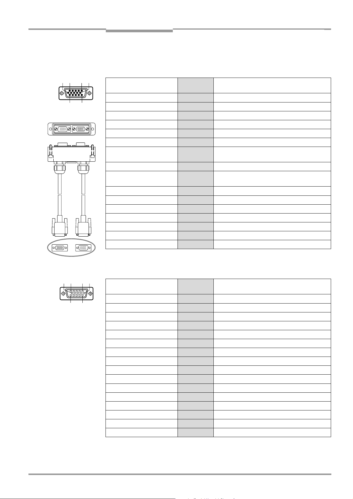
Operating Instructions Chapter 5
Electrical installation
CLV 490 Bar Code Scanner
CLV without heater
on CDM 490
5 6
1
11
10
15
5.3.3 Cable no. 2 020 307 (connector cover with parameter memory)
Pin assignment of 15-pin D Sub HD cable plug ("Host/Term" connection):
Signal 15-pin plug Connector cover
15-pin socket
V
S
RxD (RS 232), Aux 2 2
TxD (RS 232), Aux 3 3
Term (RS 422/485) 4 4
GND 5 5
RD+ (RS 422/485), Host 6 6
RD– (RS 422/485), Host
RxD (RS 232), Host
TD+ (RS 422/485), Host 8 8
TD– (RS 422/485), Host
TxD (RS 232), Host
CAN H
Reserved 11 11
CAN2 H 12 12
CAN2 L 13 13
Reserved 14 14
CAN L 15 15
Shield Housing Housing
Table 5-6: Pin assignment: 15-pin D Sub HD plug of the cable no. 2 020 307
1 1
7 7
9 9
10 10
1 10
5
15 611
Pin assignment of 15-pin D Sub HD cable socket ("I/O" connection):
Signal 15-pin
socket
V
S
1 1
IN 1 2 2
Sensor 3 3
Result 1 4 4
GND 5 5
IN 0 6 6
IN 2 7 7
Result 2 8 8
INGND 9 9
Result 3
10 10
IN 3 11 11
IN 4 12 12
I2C SDA 13 –
I2C SCL 14 –
Result 4 15 15
Shield Housing Housing
Table 5-7: Pin assignment: 15-pin D Sub HD socket of the cable no. 2 020 307
Connector cover
15-pin plug
8 009 993/O824/20-12-2004 © SICK AG · Division Auto Ident · Germany · All rights reserved 5-9
Page 60

Chapter 5 Operating Instructions
Electrical installation
CLV 490 Bar Code Scanner
CLV with heater
on CDB 420
5 6
1
11
10
15
5.3.4 Cable no. 2 033 126/2 033 127 (connector cover with parameter memory)
Pin assignment of 15-pin D Sub HD cable plug:
Signal 15-pin plug Connector cover
15-pin plug 15-pin socket
V
S
RxD (RS 232), Aux 2 – 2
TxD (RS 232), Aux 3 – 3
IN 0 (Sensor 2) 4 6 –
GND 5 – 5
RD+ (RS 422/485), Host 6 – 6
RD– (RS 422/485), Host
RxD (RS 232), Host
TD+ (RS 422/485), Host 8 – 8
TD– (RS 422/485), Host
TxD (RS 232), Host
CAN H
CAN L 11 – 15
Result 1 12 4 –
Result 2
Sensor (Sensor 1) 14 3 –
INGND 15 9 –
Shield Housing Housing
1 – –
7 – 7
9 – 9
10 – 10
13 8 –
Table 5-8: Pin assignment: 15-pin D Sub HD plug of the cable no. 2 033 126/no. 2 033 127
Open end (power supply):
Signal Wire Ferrules Connector cover
15-pin plug 15-pin socket
V
S
1 red 1 1
GND 2 black 5 5
Shield 3 grey Housing
Table 5-9: Pin assignment: open end of the cable no. 2 033 126/no. 2 033 127
The signals "IN 1" to "IN 4", "Result 3" to "Result 4" and "Term (RS-422/485)" are not available.
5-10 © SICK AG · Division Auto Ident · Germany · All rights reserved 8 009 993/O824/20-12-2004
Page 61

Operating Instructions Chapter 5
Electrical installation
CLV 490 Bar Code Scanner
CLV with heater
on CDM 490
5 6
1
11
10
15
5.3.5 Cable no. 2 030 065/2 031 034 (connector cover with parameter memory)
Pin assignment of 15-pin D Sub HD cable plug ("Host/Term" connection):
Signal 15-pin plug Connector cover
15-pin socket
V
S
RxD (RS 232), Aux 2 2
TxD (RS 232), Aux 3 3
Term (RS 422/485) 4 4
GND 5 –
RD+ (RS 422/485), Host 6 6
RD– (RS 422/485), Host
RxD (RS 232), Host
TD+ (RS 422/485), Host 8 8
TD– (RS 422/485), Host
TxD (RS 232), Host
CAN H
Reserved 11 11
CAN2 H 12 12
CAN2 L 13 13
Reserved 14 14
CAN L 15 15
Shield Housing Housing
Table 5-10: Pin assignment: 15-pin D Sub HD plug of the cable no. 2 030 065/no. 2 031 034
1 –
7 7
9 9
10 10
1 10
5
15 611
Pin assignment of 15-pin D Sub HD cable socket ("I/O" connection):
Signal 15-pin
socket
V
S
1 –
IN 1 2 2
Sensor 3 3
Result 1 4 4
GND 5 5
IN 0 6 6
IN 2 7 7
Result 2 8 8
INGND 9 9
Result 3
10 10
IN 3 11 11
IN 4 12 12
I2C SDA 13 –
I2C SCL 14 –
Result 4 15 15
Shield Housing Housing
Connector cover
15-pin plug
Table 5-11: Pin assignment: 15-pin D Sub HD socket of the cable no. 2 030 065/no. 2 031 034
8 009 993/O824/20-12-2004 © SICK AG · Division Auto Ident · Germany · All rights reserved 5-11
Page 62
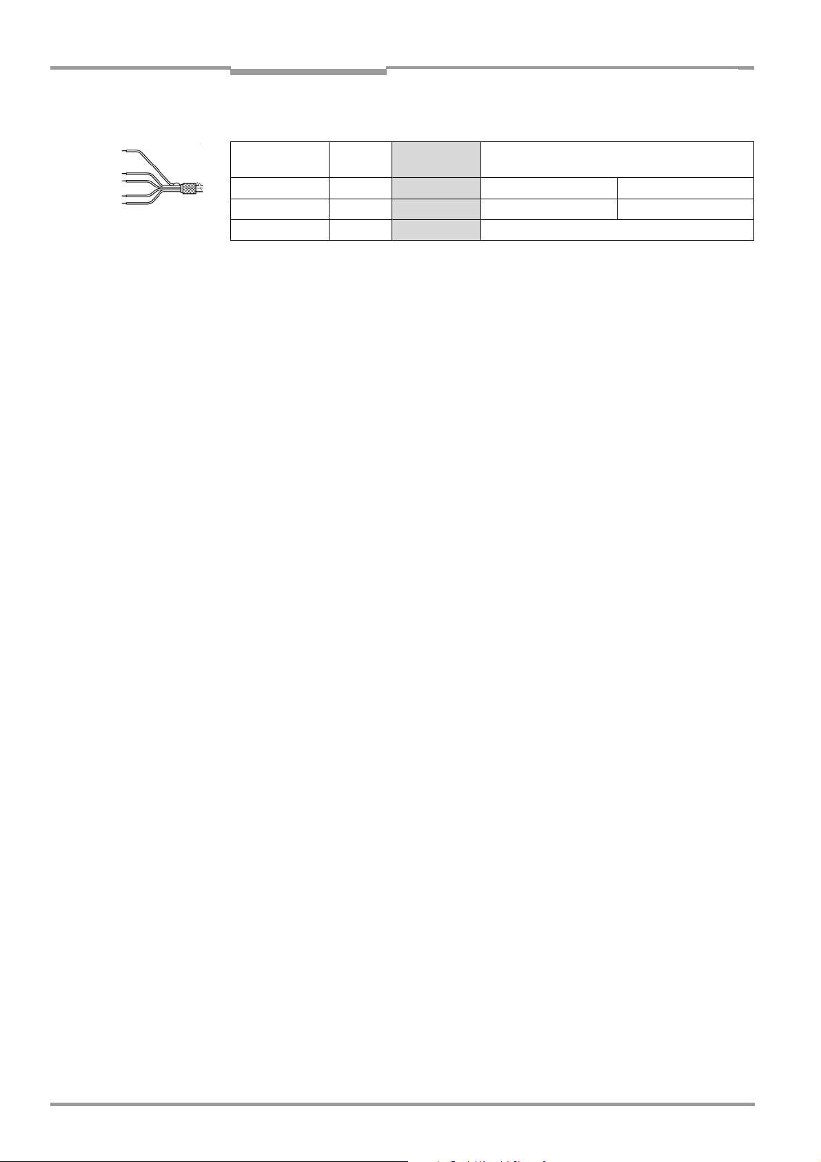
Chapter 5 Operating Instructions
Electrical installation
CLV 490 Bar Code Scanner
Open end (power supply):
Signal Wire Ferrules Connector cover
15-pin plug 15-pin socket
V
S
GND 2 black 5 5
Shield 3 grey Housing
Table 5-12: Pin assignment: open end of the cable no. 2 030 065/no. 2 031 034
1 red 1 1
5-12 © SICK AG · Division Auto Ident · Germany · All rights reserved 8 009 993/O824/20-12-2004
Page 63
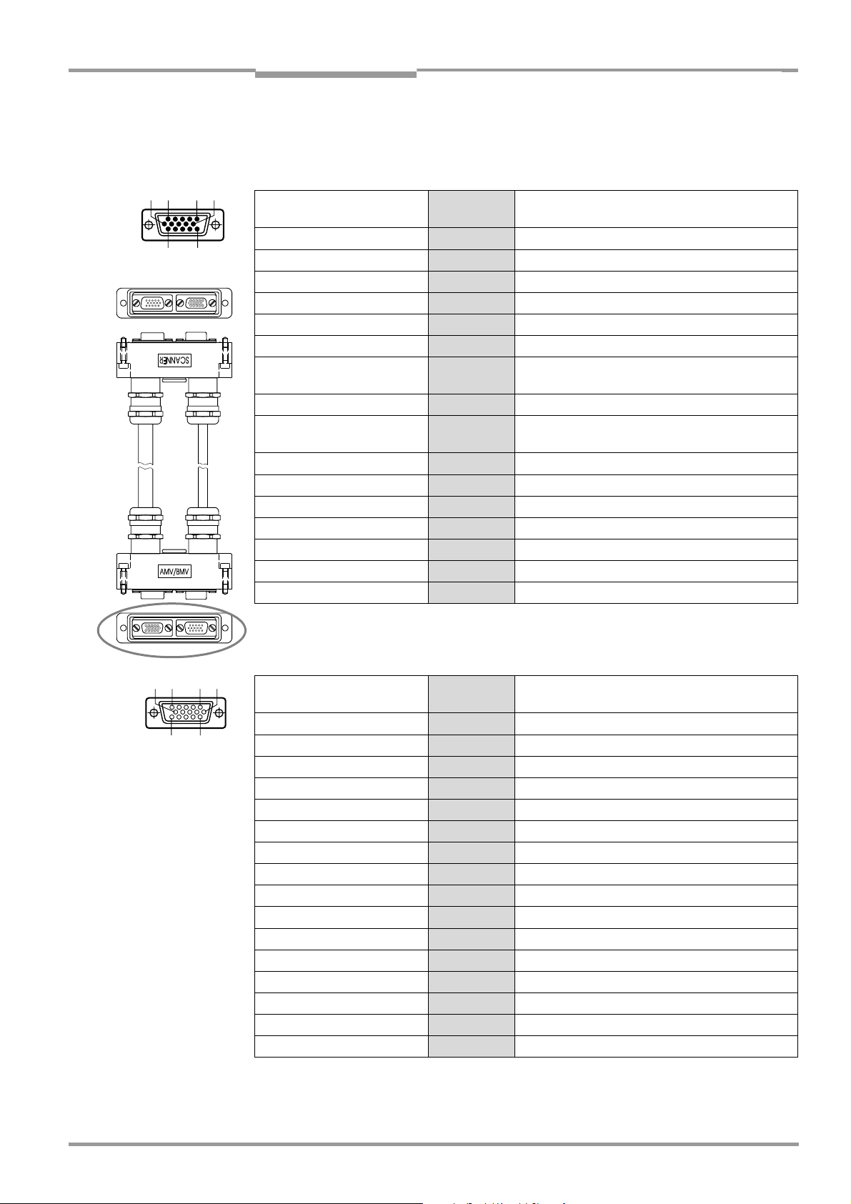
Operating Instructions Chapter 5
Electrical installation
CLV 490 Bar Code Scanner
CLV with heater
on CDM 490
5 6
1
11
10
15
5.3.6 Cable no. 2 027 543 (connector cover with parameter memory)
Pin assignment of 15-pin D Sub HD plug in connector cover "AMV/BMV":
Signal 15-pin plug Connector cover
15-pin socket
V
S
RxD (RS 232), Aux 2 2
TxD (RS 232), Aux 3 3
Term (RS 422/485) 4 4
GND 5 5
RD+ (RS 422/485), Host 6 6
RD– (RS 422/485), Host
RxD (RS 232), Host
TD+ (RS 422/485), Host 8 8
TD– (RS 422/485), Host
TxD (RS 232), Host
CAN H
Reserved 11 –
Reserved 12 –
Reserved 13 –
Reserved 14 –
CAN L 15 15
Shield Housing Housing
Table 5-13: Pin assignment: 15-pin D Sub HD plug of the cable no. 2 027 543
1 1
7 7
9 9
10 10
1 10
5
15 611
Pin assignment of 15-pin D Sub HD socket in connector cover "AMV/BMV":
Signal 15-pin
socket
V
S
1 –
IN 1 2 2
Sensor 3 3
Result 1 4 4
GND 5 5
IN 0 6 6
IN 2 7 7
Result 2 8 8
INGND 9 9
Result 3
10 10
IN 3 11 11
IN 4 12 12
Reserved 13 –
Reserved 14 –
Result 4 15 15
Shield Housing Housing
Connector cover
15-pin plug
Table 5-14: Pin assignment: 15-pin D Sub HD socket of the cable no. 2 027 543
8 009 993/O824/20-12-2004 © SICK AG · Division Auto Ident · Germany · All rights reserved 5-13
Page 64

Chapter 5 Operating Instructions
Electrical installation
CLV 490 Bar Code Scanner
CLV without heater
on power pack
1 10
5
15 611
5.3.7 Cable no. 2 020 303
Pin assignment of 15-pin D Sub HD socket/open end ("Host/Term" connection):
Signal 15-pin
socket
V
S
1 red
RxD (RS 232), Aux 2 white
TxD (RS 232), Aux 3 brown
Term (RS 422/485) 4 violet
GND 5 blue
RD+ (RS 422/485), Host 6 green
RD– (RS 422/485), Host
7 yellow
RxD (RS 232), Host
TD+ (RS 422/485), Host 8 grey
TD– (RS 422/485), Host
9 black
TxD (RS 232), Host
CAN H
10 grey-pink
Reserved 11 red-blue
CAN2 H 12 white-green
CAN2 L 13 brown-green
Reserved 14 white-yellow
CAN L 15 yellow-brown
Schirm Housing orange
Wire color
CLV without heater
on power pack
5 6
1
11
10
15
Table 5-15: Pin assignment: 15-pin D Sub HD socket/wire colors of cable no. 2 020 303
5.3.8 Cable no. 2 020 264
Pin assignment of 15-pin D Sub HD plug/open end ("I/O" connection):
Signal 15-pin plug Wire color
V
S
IN 1 2 white
Sensor 3 brown
Result 1 4 violet
GND 5 blue
IN 0 6 green
IN 2 7 yellow
Result 2 8 grey
INGND 9 black
Result 3
IN 3 11 red-blue
IN 4 12 white-green
I2C SDA 13 brown-green
I2C SCL 14 white-yellow
Result 4 15 yellow-brown
Shield Housing orange
Table 5-16: Pin assignment: 15-pin D Sub HD plug/wire colors of cable no. 2 020 264
1 red
10 grey-pink
5-14 © SICK AG · Division Auto Ident · Germany · All rights reserved 8 009 993/O824/20-12-2004
Page 65

Operating Instructions Chapter 5
Electrical installation
CLV 490 Bar Code Scanner
CLV without heater
on power pack
Cable 1Cable 2
5.3.9 Cable no. 2 020 981 (connector cover with parameter memory)
Cable 1, open end ("Host/Term" connection):
Signal Wire color Connector cover
15-pin socket
V
S
RxD (RS 232), Aux white 2
TxD (RS 232), Aux brown 3
Term (RS 422/485) violet 4
GND blue and grey-brown 5
RD+ (RS 422/485), Host green 6
RD– (RS 422/485), Host
RxD (RS 232), Host
TD+ (RS 422/485), Host grey 8
TD– (RS 422/485), Host
TxD (RS 232), Host
CAN H
Reserved red-blue 11
CAN2 H white-green 12
CAN2 L brown-green 13
Reserved white-yellow 14
CAN L yellow-brown 15
Shield orange Housing
Table 5-17: Wire colors of cable no. 2 020 981, cable 1 ("Host/Term" connection)
red and pink 1
yellow 7
black 9
grey-pink 10
Cable 2, open end ("I/O" connection):
Signal Wire color Connector cover
15-pin plug
V
S
IN 1 white 2
Sensor brown 3
Result 1 violet 4
GND blue and grey-brown 5
IN 0 green 6
IN 2 yellow 7
Result 2 grey 8
INGND black 9
Result 3
IN 3 red-blue 11
IN 4 white-green 12
Reserved –13
Reserved –14
Result 4 yellow-brown 15
Shield orange Housing
red and pink 1
grey-pink 10
Table 5-18: Wire colors of cable no. 2 020 981, cable 2 ("I/O" connection)
8 009 993/O824/20-12-2004 © SICK AG · Division Auto Ident · Germany · All rights reserved 5-15
Page 66

Chapter 5 Operating Instructions
Electrical installation
CLV 490 Bar Code Scanner
CLV with/without
heater on power pack
Cable 2Cable 1
5.3.10 Cable no. 2 021 267 (connector cover)
Cable 1, open end (connection for data and function interfaces):
Signal Wire color Connector cover
15-pin plug 15-pin socket
IN 1 white 2 –
Sensor brown 3 –
Result 1 green 4 –
IN 0 yellow 6 –
IN 2 grey 7 –
Result 2 pink 8 –
INGND blue 9 –
Result 3 red 10 –
IN 3 black 11 –
IN 4 violet 12 –
Result 4 grey-pink 15 –
RxD (RS 232), Aux red-blue – 2
TxD (RS 232), Aux white-green – 3
Term (RS 422/485) brown-green – 4
RD+ (RS 422/485), Host white-yellow – 6
RD– (RS 422/485), Host
RxD (RS 232), Host
TD+ (RS 422/485), Host white-grey – 8
TD– (RS 422/485), Host
TxD (RS 232), Host
Shield orange Housing
yellow-brown – 7
grey-brown – 9
Table 5-19: Wire colors of cable no. 2 021 267, cable 1 (connection for data and function interfaces)
Cable 2, open end (connection for power supply):
Signal Wire color Connector cover
15-pin plug 15-pin socket
V
S
red – 1
GND black – 5
Table 5-20: Wire colors of cable no. 2 021 267, cable 2 (connection for power supply)
The signals of the CAN interface (CAN H, CAN L, CAN2 H, CAN2 L) are not available.
5-16 © SICK AG · Division Auto Ident · Germany · All rights reserved 8 009 993/O824/20-12-2004
Page 67
Operating Instructions Chapter 5
CLV 490 Bar Code Scanner
Electrical installation
5.4 Preparations for electrical installation
5.4.1 Requirements for the host interface
The host interface of the CLV can be operated as an RS 422/485 or an RS 232 interface.
Table 5-21 shows the recommended maximum cable lengths as a function of the selected
data transfer rate.
Interface type Transfer rate Distance from host
RS 232 Up to 19,200 bd
38,400 to 57,600 bd
RS 422/485
1) with suitable line termination according to specifications
Table 5-21: Maximum cable lengths between the CLV and host
1)
Max. 38,400 bd
Max. 57,600 bd
¾ To prevent interference, do not lay the cables parallel with power supply and motor
cables over long distances, e. g. in cable ducts.
5.4.2 Supply voltage
Max. 10 m (32.8 ft)
Max. 3 m (9.84 ft)
Max. 1,200 m (3,936 ft)
Max. 500 m (1,640 ft)
The CLV requires a supply voltage of 18 to 30 V DC for operation without a heater and
24 V DC +20 %/–10 % for operation with a heater (functional extra-low voltage in accordance with IEC 364-4-41). The functional extra-low voltage can be generated by using a
safety transformer pursuant to IEC 742.
The power consumption of the individual types is as follows:
Type Voltage Scanning method Heater
CLV 490-0010/-2010/-6010
CLV 490-1010/-3010/-7010
CLV 490-0011/-2011/-6011
CLV 490-1011/-3011/-7011
1) switching outputs not connected
Table 5-22: Power consumption of the CLV
18 to 30 V DC
18 to 30 V DC
24 V DC
+20 %/–10 %
Line scanner
Line scanner with
oscillating mirror
Line scanner
Line scanner with
oscillating mirror
No
No
Yes
Yes
Power consumption
11 W (typ.)/max. 16 W
13 W (typ.)/max. 18 W
75 W (typ.)/max. 90 W
75 W (typ.)/max. 100 W
Via the CDB 420 or CDM 490 Connection Module the CLV without heater is supplied with
18 to 30 V DC, the CLV with heater is supplied with 24 V DC +20 %/−10 %.
If the CMP 490 Power Supply Module in the CDM 490 is used for the CLV without heater,
the input voltage is 100 to 250 V AC/50 to 60 Hz.
Power-up delay
The selected device number (default: 1) affects the power-up delay of the device. This is
useful if a large number of CLVs (e. g. in the SICK CAN Scanner Network) are to be supplied
from one power source. Table 5-23 contains a list of the available intervals.
1)
Connection
module
CDB 420 or
CDM 490
CDB 420 or
CDM 490
Device number GN Power-up delay Device number GN Power-up delay
1; 11; 21; 31 0 ms 6; 16; 26 2,000 ms
2; 12; 22 400 ms 7; 17; 27 2,400 ms
3; 13; 23 800 ms 8; 18; 28 2,800 ms
4; 14; 24 1,200 ms 9; 19; 29 3,200 ms
5; 15; 25 1,600 ms 10; 20; 30 3,600 ms
Table 5-23: Power-up delay as a function of the device number GN
8 009 993/O824/20-12-2004 © SICK AG · Division Auto Ident · Germany · All rights reserved 5-17
Page 68

Chapter 5 Operating Instructions
Electrical installation
CLV 490 Bar Code Scanner
Tip
The device number can be selected on the DEVICE CONFIGURATION tab in the "CLV-Setup"
program.
5.4.3 Non-SICK Power supply unit/connections without the Connection Module
Power output
If an non-Sick Power supply unit is used, it must be capable of providing the following voltage
and power values:
• For CLV without heater: 18 to 30 V DC, min. 20 W continuous power output
• For CLV with heater: 24 V DC +20 %/–10 %, min. 100 W
The non-Sick Power supply unit must provide the functional extra-low voltage in accordance
with IEC 364-4-41.
The output circuit must be reliably electrically isolated from the input circuit. To do so,
use a safety isolating transformer pursuant to IEC 742.
Wire cross-section
The wire cross-section for the power supply (Pin 1/Pin 5) should be at least 0.15 mm
(approx. 26 AWG) or 0.75 mm
2
(approx. 20 AWG) for CLVs with heater, with a max. length
2
of 10 m (32.8 ft).
5-18 © SICK AG · Division Auto Ident · Germany · All rights reserved 8 009 993/O824/20-12-2004
Page 69

Operating Instructions Chapter 5
CLV 490 Bar Code Scanner
Electrical installation
5.5 Electrical installation procedure
5.5.1 Individual steps
• Connect the power supply
• Connect the host interface
• Connect the PC (connect the terminal interface)
• Connect the "Sensor" and "IN 0" to "IN 4" switching inputs
• Connect the "Result 1" to "Result 4" switching outputs
5.5.2 Tools
• Tool
• Digital measuring device (current/voltage measurement)
5.5.3 Connecting the supply voltage
a) SICK CDB 420 or CDM 490 Connection Module
If the CLV is powered via the SICK Connection Modules using the cables no. 2 027 046,
no. 2 030 023, no. 2 020 307, or no. 2 027 543, the supply voltage does not have to be
wired separately.
Using the cables with open ends no. 2 033 126, no. 2 033 127, no. 2 030 065, or
no. 2 031 034, the supply voltage must be wired separately at the screw terminal strips in
the connection module.
Connecting the CLV without connector cover:
1. Make sure that the power supply to the connection module is switched off.
2. Connect the "Host/Term" and "I/O" connections on the CLV to the corresponding connections on the CDM 490 Connection Module using two cables no. 2 020 302 or no.
2 021 815 and secure them tightly on both sides.
Connecting the CLV with connector cover/connector cover with parameter memory:
1. Connect the connector cover of the cable no. 2 027 046, no. 2 030 023,
no. 2 033 126, or no. 2 033 127 to the "Host/Term" and "I/O" connections on the CLV
and secure it tightly.
2. Connect the free 15-pin cable plug to the corresponding socket on the CDB 420
Connection Module and secure them tightly.
For the cable no. 2 033 126 or no. 2 033 127, lead additionally the cable with open
end through one of the cable glands and connect it to the screw terminals 3, 4, and 6.
– or –
1. Connect the connector cover of the cable no. 2 020 307, no. 2 030 065,
no. 2 031 034, or no. 2 027 543 to the "Host/Term" and "I/O" connections on the CLV
and secure it tightly.
2. Connect the free 15-pin cable connections to the corresponding connections on the
CDM 490 Connection Module and secure them tightly.
For the cable no. 2 030 065 or no. 2 031 034, lead additionally the cable with open
end through one of the cable glands and connect it to the screw terminals 3, 4, and 6.
The data and function interfaces of the CLV are connected to the Connection Module.
8 009 993/O824/20-12-2004 © SICK AG · Division Auto Ident · Germany · All rights reserved 5-19
Page 70

Chapter 5 Operating Instructions
Electrical installation
CLV 490 Bar Code Scanner
See also the Fitting Instructions for the "Cold-resistent cable no. 2 033 126/no. 2 033 127"
(order no. 8 010 971, German/English) used for CDB 420 respectively the Fitting Instructions for the "Cold-resistent cable no. 2 030 065/no. 2 031 034" (order no 8 010 972,
German/English) used for CDM 490.
b) Power supply via non-SICK Power pack
Connecting the CLV without connector cover:
1. Connect the cable socket on cable no. 2 020 303 on the "Host/Term" connection and
screw it tightly into position.
2. Connect the cable plug on the cable no. 2 020 264 to the "I/O" connection and screw
it tightly into position.
3. Connect the power supply to the red wire (Pin 1, V
) and blue wire (Pin 5, GND) on cable
S
no. 2 020 303. See also Table 5-15, Page 5-14
Connecting the CLV with connector cover/connector cover with parameter memory:
1. Connect the connector cover of the cable no. 2 020 981 or no. 2 021 267 to the
"Host/Term" and "I/O" connections on the CLV and secure it tightly.
2. For the cable no. 2 020 981 connect the power supply to the red/pink wire (Pin 1, VS)
and the blue/grey-brown wire (Pin 5, GND) of cable 1. See also Table 5-17, Page 5-15.
For the cable no. 2 021 267 connect the power supply to the red wire (Pin 1, VS) and
the black wire (Pin 5, GND) of cable 2. See also Table 5-20, Page 5-16.
The CLV is connected to the supply voltage.
5-20 © SICK AG · Division Auto Ident · Germany · All rights reserved 8 009 993/O824/20-12-2004
Page 71
Operating Instructions Chapter 5
CLV 490 Bar Code Scanner
Electrical installation
5.5.4 Connecting the host interface
RS 232
( )=9-pin Sub D
( )= 9-pin D-Sub-
plug on PC
connector at PC
RS 422
CAN-Network: Connection diagram for SICK CAN Scanner Network
see "CLV Connect" program on CD-ROM
Fig. 5-3: Connecting the host interface
Risk of damage to the interface module
Electrical components in the CLV may be damaged if the host interface is connected
incorrectly.
¾ Connect the host interface as shown in Fig. 5-3.
¾ Check the connections carefully before you switch on the CLV.
¾ Connect the host interface on the CLV to the host using shielded cables (EMC require-
ments). Ensure that the maximum cable lengths are not exceeded (see Table 5-21,
Page 5-17).
Default In the default setting, the CLV communicates with the host via the host interface using the
values shown in Table 5-24.
Parameter Value
Physical design RS 422/485
Data transfer rate 9,600 bd
Data bits 8
Parity None
Stop bits 1
Protocol SICK (start character: STX, stop character: ETX, no request for repeat:
none, timeout: 50 ms)
Table 5-24: Communication parameters for the host interface (default setting)
8 009 993/O824/20-12-2004 © SICK AG · Division Auto Ident · Germany · All rights reserved 5-21
Page 72
Chapter 5 Operating Instructions
Electrical installation
CLV 490 Bar Code Scanner
For connecting the host interface via the CDB 420 or CDM 490 Connection Module, see
the Operating Instructions for the "CDB 420 Connection Module" (no. 8 010 001, German/
English) respectively the Operating Instructions for the "CDM 490 Connection Module"
(no. 8 010 005, German/English).
Terminating the RS 422 interface:
The interface can be terminated in the Connection Module. See the Operating Instructions
for the "CDB 420 or CDM 490 Connection Modules".
Activating the RS 232 interface:
The RS 232 interface can be activated with the "CLV-Setup" program:
1. Choose the H
2. Choose the RS 232 option from the H
OST INTERFACE tab.
ARDWARE drop-down list under DATA FORMAT.
3. Download the data to the CLV by clicking in the toolbar.
The D
OWNLOAD PARAMETERS dialog box is displayed.
4. Confirm the dialog box by choosing P
ERMANENT.
The CLV uses the RS 232 version of the host interface.
Tip The communication parameters can be changed, if necessary, on the H
To do so, change the values under D
ATA FORMAT and INTERFACE PROTOCOL.
OST INTERFACE tab.
5.5.5 Connecting the CAN interface
Connecting the CAN Interface 1 and configuring the CLV to use the device in the SICKspecific CAN Scanner Network or in a CANopen network see the Operating Instructions
“Application of the CAN interface“ (no. 8 009 180, English edition).
5.5.6 Connecting the PC
The CLV is operated and configured with the PC-based "CLV-Setup" program. In order to do
so, you must connect the device to the PC via the terminal interface (auxiliary interface). Unlike the host interface, the terminal interface has a permanent data format and a fixed data
transfer rate. Fig. 5-4 shows how the terminal interface is connected. The cable length
should not be more than 10 m (32.8 ft).
RS 232
( ) = 9-pin Sub D
plug on PC
Fig. 5-4: Connecting the terminal interface
1. Switch off the PC and power supply to the CDB 420 or CDM 490 Connection Module.
2. Connect the PC to the internal, 9-pin "Aux" plug on the Connection Module.
To do so, use a 3-core RS 232 data cable (null modem cable), e. g. no. 2 014 054
(RxD and TxD crossed).
– or –
Without the SICK Connection Module:
Connect the PC as shown in Fig. 5-4.
5-22 © SICK AG · Division Auto Ident · Germany · All rights reserved 8 009 993/O824/20-12-2004
Page 73

Operating Instructions Chapter 5
CLV 490 Bar Code Scanner
Electrical installation
3. Switch on the PC and power supply to the SICK Connection Module.
4. Set the communication parameters (see Chapter 10.6.3 Starting CLV-Setup,
Page 10-46).
CLV
Tip
In the default configuration, the terminal interface outputs the reading result in reading
diagnosis mode.
You can change the operating mode to M
A
UXILIARY INPUT or EXTERNAL DATA STRING INPUT on the AUXILARY INTERFACE tab in the "CLV-
ONITOR HOST INTERFACE, to MONITOR HOST INTERFACE 2,
Setup" program.
5.5.7 Connecting the "Sensor" switching input
If a reading procedure is to be triggered on the CLV by an external sensor, the reading pulse
sensor must be connected to the "Sensor" switching input. This trigger type is selected in
the default setting of the CLV. Fig. 5-5 shows the connections for the "Sensor" switching input. Table 5-25 contains the characteristic data for this input.
PNP sensor
V
S
V
2k6
Sensor
IN GND
GND
1
S
3
9
5
V
S
OUT
GND
V
S
GND
Switch
1
3
9
5
VS= 18 to 30 V DC for CLV without heater, 24 V DC +20 % /–10 % for CLV with heater
Fig. 5-5: Connections of the "Sensor" switching input
¾ Connect the reading pulse sensor as shown in Fig. 5-5.
Switching mode Current at the input starts the reading interval on the CLV.
Properties – optodecoupled, non-interchangeable
Electrical values
Table 5-25: Characteristic data of the "Sensor" switching input
Tip
You can change the switching mode (polarity, debouncing, response for first pulse after
power-up) of the "S
Setup" program.
¾ Click the R
EADING TRIGGER PARAMETERS button.
Enter the values in the dialog box displayed.
Perform a download to the CLV.
(default: active high, debouncing: 20 to 30 ms (standard))
– can be connected to PNP output on a sensor
Low: –30 V
ENSOR" switching input on the DEVICE CONFIGURATION tab in the "CLV-
≤ V
≤ +2 V High: +7 V ≤ VI ≤ +13 V
I
8 009 993/O824/20-12-2004 © SICK AG · Division Auto Ident · Germany · All rights reserved 5-23
Page 74
Chapter 5 Operating Instructions
Electrical installation
CLV 490 Bar Code Scanner
For connecting the switching input via the CDB 420 or CDM 490 Connection Module, see
the Operating Instructions for the "CDB 420 Connection Module" (no. 8 010 001, German/
English) respectively the Operating Instructions for the "CDM 490 Connection Module"
(no. 8 010 005, German/English).
Note An external pulse is not required for Percentage Evaluation mode.
5.5.8 Connecting the "IN 0" to "IN 4" switching inputs
If the Autofocus function is not used and the CLVs dynamic focus control function is to be
triggered by external sensors, the sensors are connected to the five inputs "IN 0" to "IN 4".
Together with the internal assignment table, these can be used to configure a maximum of
32 switching states for up to 8 distance configurations. The dynamic focus control function
is selected for all inputs by default.
Additional function "IN 3":
The "IN 3" input can also be used as a trigger source for the One-Shot function of the oscillating mirror.
Additional function "IN 4":
The input "IN 4" can also be used as:
• A trigger source for the One-Shot function of the oscillating mirror
• An input for a belt increment signal in reading mode "Tracking" and/or for separating
bar codes of the same symbology with identical content
• A trigger source for the end of reading interval
In this case, a maximum of 16 switching statuses can be used for dynamic focus control.
Fig. 5-6 shows the connections for the "IN 0" to "IN 4" switching inputs. Table 5-26 shows
the pin assignment on the CLV. Table 5-27 contains the characteristic data for these inputs.
Table 5-28 shows the input combinations based on the distance configurations. The inter-
action of the switching input functions is shown in Table 5-29, Page 5-26
V
V
S
CLV
= 18 to30 V DC for CLV without heater, 24 V DC +20 % /–10 % for CLV with heater
V
S
Fig. 5-6: Connections of the "IN 0" to "IN 4" switching inputs
S
2k6
IN X
IN GND
GND
1
Y
9
5
V
S
OUT
GND
PNP sensor
GND
V
S
Pin assignment for
IN X see Table 5-26
Switch
1
Y
9
5
Note In the CDB 420 Connection Module only the signals of the "Sensor“ and "IN 0“ switching
inputs can be connected using the terminal strips.
5-24 © SICK AG · Division Auto Ident · Germany · All rights reserved 8 009 993/O824/20-12-2004
Page 75
Operating Instructions Chapter 5
Electrical installation
CLV 490 Bar Code Scanner
Input
"IN X"
CLV "I/O" connection
Pin Y
IN 0 Pin 6
IN 1 Pin 2
IN 2 Pin 7
IN 3 Pin 11
IN 4 Pin 12
Table 5-26: Pin assignment for "IN 0" to IN 4" switching inputs
¾ Connect the sensors as shown in Fig. 5-6.
For connecting the switching inputs via the CDB 420 or CDM 490 Connection Module, see
the Operating Instructions for the "CDB 420 Connection Module" (no. 8 010 001, German/
English) respectively the Operating Instructions for the "CDM 490 Connection Module"
(no. 8 010 005, German/English).
Function Trigger source for dynamic focus control
"IN 3" alternative: – trigger source for One Shot on oscillating mirror
"IN 4" alternative: – trigger source for One Shot on oscillating mirror
– belt increment input
– trigger source for end of reading interval
Default setting "IN 3" and "IN 4": dynamic focus control
Switching mode Active when input energized (high)
Properties – Optodecoupled, non-interchangeable
– Can be connected to PNP output on a sensor
Electrical values
Low: –30 V
Table 5-27: Characteristic data of the "IN 0" to "IN 4" switching inputs
≤ V
≤ +2 V High: +7 V ≤ VI ≤ +13 V
I
Switching inputs
1)
Logic state
"IN 4" to "IN 0"
inputs
Assignment
table index
Content Assignment Table Distance Config.
Default setting Example:
Photoelectric switches
(bright switching)
0 0 0 0 0 N 1 DC 1 DC 6
0 0 0 0 1 N 2 DC 2 DC 5
0 0 0 1 0 N 3 DC 3 DC 4
0 0 0 1 1 N 4 DC 4 DC 4
0 0 1 0 0 N 5 DC 5 DC 3
0 0 1 0 1 N 6 DC 6 DC 3
0 0 1 1 0 N 7 DC 7 DC 3
0 0 1 1 1 N 8 DC 8 DC 3
0 1 0 0 0 N 9 DC 8 DC 2
0 1 0 0 1 N 10 DC 8 DC 2
0 1 0 1 0 N 11 DC 8 DC 2
0 1 0 1 1 N 12 DC 8 DC 2
0 1 1 0 0 N 13 DC 8 DC 2
0 1 1 0 1 N 14 DC 8 DC 2
0 1 1 1 0 N 15 DC 8 DC 2
0 1 1 1 1 N 16 DC 8 DC 2
1 0 0 0 0 N 17 DC 8 DC 1
1 0 0 0 1 N 18 DC 8 DC 1
1 0 0 1 0 N 19 DC 8 DC 1
1 0 0 1 1 N 20 DC 8 DC 1
Table 5-28: Dynamic focus control: switching inputs/distance configuration assignment table
2)
8 009 993/O824/20-12-2004 © SICK AG · Division Auto Ident · Germany · All rights reserved 5-25
Page 76

Chapter 5 Operating Instructions
Electrical installation
CLV 490 Bar Code Scanner
Switching inputs
Logic state1)
"IN 4" to "IN 0"
inputs
Assignment
table index
Content Assignment Table Distance Config.
Default setting Example:
Photoelectric switches
(bright switching)
2)
1 0 1 0 0 N 21 DC 8 DC 1
1 0 1 0 1 N 22 DC 8 DC 1
1 0 1 1 0 N 23 DC 8 DC 1
1 0 1 1 1 N 24 DC 8 DC 1
1 1 0 0 0 N 25 DC 8 DC 1
1 1 0 0 1 N 26 DC 8 DC 1
1 1 0 1 0 N 27 DC 8 DC 1
1 1 0 1 1 N 28 DC 8 DC 1
1 1 1 0 0 N 29 DC 8 DC 1
1 1 1 0 1 N 30 DC 8 DC 1
1 1 1 1 0 N 31 DC 8 DC 1
1 1 1 1 1 N 32 DC 8 DC 1
1) 1 = energized (active); 0 = deenergized (inactive)
2) Distance configuration (DC): data record for focus position
Table 5-28: Dynamic focus control: switching inputs/distance configuration assignment table (contd.)
Parameter settings of switching inputs Effects
"IN 3" "IN 4"
Focus control
)
1
Focus control
1)
"IN 3" switches the focus position in combination with "IN 0" to "IN 2" and "IN 4"
Focus control
1)
One shot "IN 4" triggers the one shot
"IN 3" switches the focus position in combination with "IN 0" to "IN 2"
Focus control
1
Increment counter "IN 4" receives increment signals
)
"IN 3" switches the focus position in combination with "IN 0" to "IN 2"
Focus control
1
End of reading interval "IN 4" triggers the end of reading interval
)
"IN 3" switches the focus position in combination with "IN 0" to "IN 2"
One shot
Focus control
1)
"IN 0" to "IN 2" switch the focus position
"IN 3" triggers the one shot
"IN 4" has no effect
One shot One shot "IN 4" triggers the one shot
"IN 0" to "IN 2" switch the focus position
"IN 3" has no effect
One shot Increment counter "IN 0" to "IN 2" switch the focus position
"IN 3" triggers the one shot
"IN 4" receives increment signals
One shot End of reading interval "IN 0" to "IN 2" switch the focus position
"IN 3" triggers the one shot
"IN 4" triggers the end of reading interval
1) depending on the assignment table
Table 5-29: Combination of the functions of the "IN 0" to "IN 4" switching inputs
Tip
The function assigned to the "IN 3" and "IN 4" input can be modified on the DEVICE CONFI-
GURATION tab in the "CLV-Setup" program.
¾ Click the F
UNCTION IN 3 and FUNCTION IN 4 drop-down list and choose the required func-
tion.
Perform a download to the CLV.
5-26 © SICK AG · Division Auto Ident · Germany · All rights reserved 8 009 993/O824/20-12-2004
Page 77
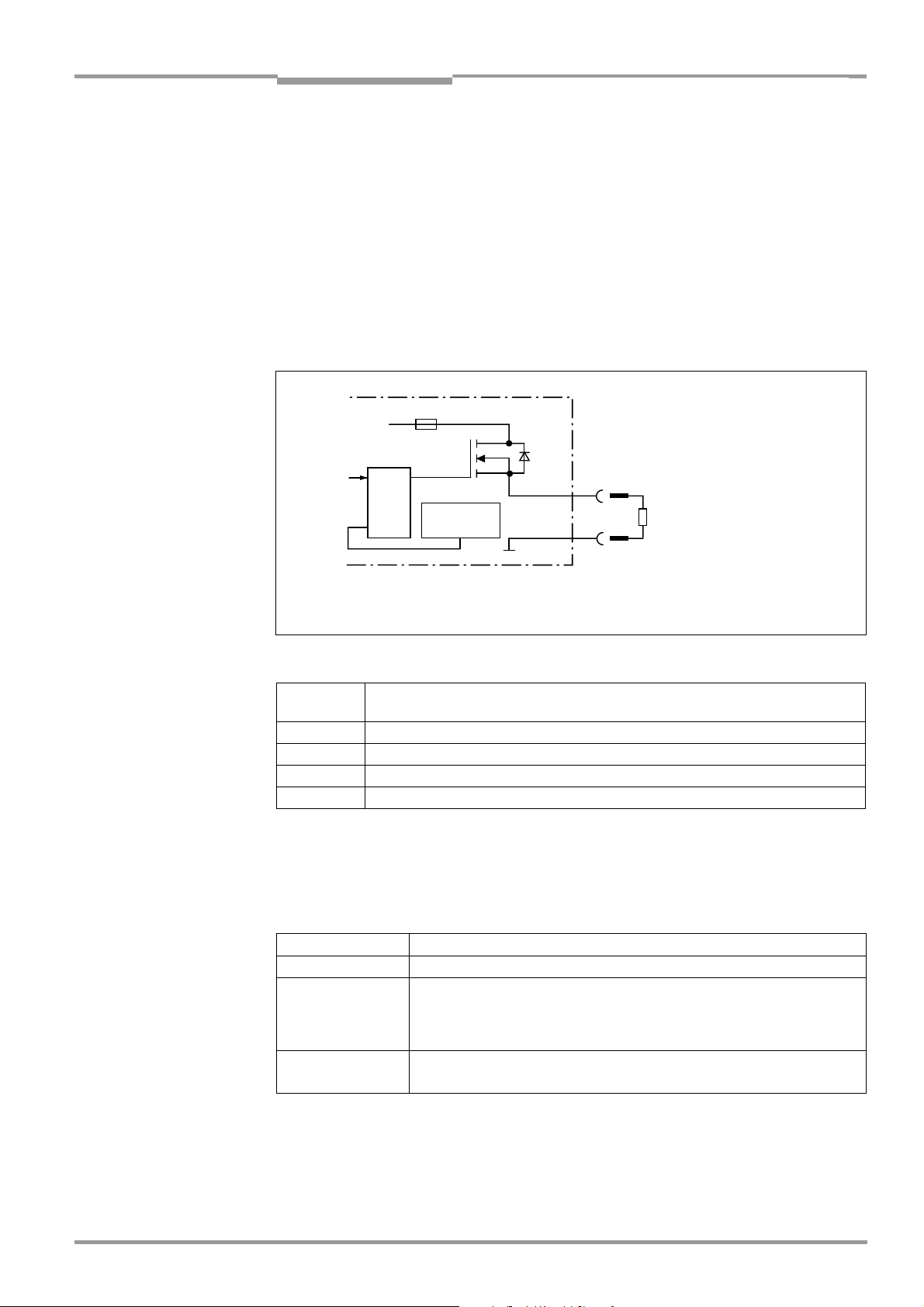
Operating Instructions Chapter 5
Electrical installation
CLV 490 Bar Code Scanner
5.5.9 Connecting the "Result 1" to "Result 4" switching outputs
The four switching outputs can be assigned different functions for outputting result statuses
independently of each other. If the assigned event occurs during the reading procedure, the
corresponding switching output becomes live at the end of the reading pulse for the selected pulse duration. The pulse duration can be set individually for each output.
The "Read Result" LED is linked to the "Result 2" output and lights up in Reading mode for the
selected pulse duration and function of the result status display (default: Good Read, 100 ms).
Fig. 5-7 shows the connections for the "Result 1" to "Result 4" switching outputs.
Table 5-30 shows the pin assignment on the CLV. Table 5-31 contains the characteristic
data for these outputs. The four outputs have the same characteristic data.
Fuse
V
S
Pulse duration
depending
on setting:
– 10 ms to 900 ms
Logic
Temperature
sensor
Result X
GND
Y
5
– 100 ms to 9,900 ms
–00: static
R
L
Pin assignment for
VS= 18 to 30 V DC for CLV without heater,
24 V DC +20 %/–10 % for CLV with heater
"Result X"
see Table 5-30
Fig. 5-7: Connections of the "Result 1" to "Result 4" switching outputs
Output
"Result X"
CLV "I/O" connection
Pin Y
Result 1 Pin 4
Result 2 Pin 8
Result 3 Pin 10
Result 4 Pin 15
Table 5-30: Pin assignment for "Result 1" to "Result 4" switching outputs
(to the end of next
reading pulse)
¾ Connect the outputs as shown in Fig. 5-7.
Note In the CDB 420 Connection Module only the signals of the "Result 1“ and "Result 2“ switch-
ing outputs can be connected using the terminal strips.
"
Switching mode PNP-switching with respect to the supply voltage V
S
Properties The current in the event of a short-circuit is limited to 0.7 A
Function
assignment
(default)
"Result 1": Device Ready (static), polarity: not inverted
"Result 2": Good Read (100 ms), polarity: not inverted
"Result 3": No Ready (100 ms), polarity: not inverted
"Result 4": Match 1 (100 ms), polarity: not inverted
Electrical values
0 V
≤ V
≤ 100 mA
I
0
≤ 30 V Guaranteed: VO ≤ VS ≤ 1.3 V with I
O
≤ 100 mA
0
Table 5-31: Characteristic data of the "Result 1" to "Result 4" switching outputs
Note If the "Device Ready" function is chosen, the CLV outputs a static pulse in Reading mode.
8 009 993/O824/20-12-2004 © SICK AG · Division Auto Ident · Germany · All rights reserved 5-27
Page 78

Chapter 5 Operating Instructions
Electrical installation
CLV 490 Bar Code Scanner
For connecting the switching outputs via the CDB 420 or CDM 490 Connection Module, see
the Operating Instructions for the "CDB 420 Connection Module" (no. 8 010 001, German/
English) respectively the Operating Instructions for the "CDM 490 Connection Module"
(no. 8 010 005, German/English).
Tip
The output function, pulse duration (timer), and polarity of the signals can be changed on
the D
EVICE CONFIGURATION tab in the "CLV-Setup" program.
¾ Click the R
ESULT OUTPUTS Parameter button.
Enter the values in the dialog box displayed.
Perform a download to the CLV.
Recommendation ¾ To check the switching functions using a high-impedance digital voltmeter, connect a
load to the outputs to prevent incorrect voltage values/switching statuses from being
displayed.
5-28 © SICK AG · Division Auto Ident · Germany · All rights reserved 8 009 993/O824/20-12-2004
Page 79

Operating Instructions Chapter 6
CLV 490 Bar Code Scanner
Operation
6 Operation
6.1 Overview of steps for starting up the CLV
• Start up the CLV with the factory default settings (quick start).
With this configuration, the CLV can be operated without being connected to a PC.
• Connect the PC. See Chapter 5.5.6 Connecting the PC, Page 5-22 and Chapter 10.6
Installing and operating the "CLV-Setup" program, Page 10-43.
• Configure (parameterize) the CLV for the application.
6.2 Default settings
Table 6-1, Page 6-2 and Table 6-2 contain an overview of the factory default settings for
the CLV. The default parameters are such that the CLV can be put into operation either
straight away or following a few minor adjustments. A PC does not need to be connected to
start up the CLV with the default settings.
The default settings are stored permanently both in the ROM of the CLV and in the CLVSetup database. They can be loaded to the RAM of the CLV at any time and displayed in the
tabs of the "CLV-Setup" program.
Displaying and printing out a complete set of default settings in CLV-Setup:
1. To save the current settings in the parameter set:
Choose F
Setup saves the current settings in a configuration file with the extension "*.scl".
2. Click in the toolbar.
CLV-Setup loads the default settings from its internal database and displays them in the
tabs.
3. Click in the toolbar.
The P
4. If desired, a comment can be entered in the input field for the header of the printout.
Confirm the entry with OK. The P
displayed.
5. Make the appropriate entries in the dialog box and confirm these with OK.
CLV-Setup prints out the complete set of default settings in the form of a table. The header
contains the company and user names that were entered during the CLV-Setup installation
routine.
ILE and SAVE AS, and enter a file name in the dialog box that appears. CLV-
RINT FILE dialog box is displayed.
RINT dialog box for configuring the printer then is
8 009 993/O824/20-12-2004 © SICK AG · Division Auto Ident · Germany · All rights reserved 6-1
Page 80

Chapter 6 Operating Instructions
Operation
CLV 490 Bar Code Scanner
6.2.1 Default settings of the line scanner CLV 490 (all variants)
Parameter Default setting
Decoder SMART/standard
Active codes types Code 39, 2/5 Interleaved, Code 128
Code length Freely assignable (2/5 Interleaved: interval 4 to 50 characters)
Start/stop ratio Automatic
Min./max. code position 5/ 95 CP
No. of multiple reads 3
Min./max. no. codes 1
Scanning frequency 800 Hz
Distance measurement Active
Background Default (2,200 mm (86.7 in) along entire distance profile)
Autofocus mode Min. distance
Range 400 to 2,200 mm (15.8 to 86.7 in)
Scan angle –27° to +27°
Focus control trigger Autofocus, switchover immediately (synchronously)
Reading pulse source Start: "Sensor" switching input (active: high); end: "Sensor" switching input
"IN 0"to "IN 4" switching inputs Focus position changeover (without meaning for autofocus function)
"Sensor" switching input Start and end of reading pulse (level: active high), debouncing 20 to 30 ms
Switching outputs Not inverted; pulse duration: 100 ms
Status output function Result 1: Device Ready (static); Result 2: Good Read; Result 3: No Read; Result 4: Match 1
CLV arrangement Stand-alone
Read result output Host interface
Device number 1
Start option Load the parameter set of the external parameter memory
Host interface (type) RS 422/485
Protocol NAK; start character: STX, stop character: ETX
Transmission rate 9 600 bd
Data format 8 data bits, no parity, 1 stop bit
Output format Good Read: Header: blank, Code Info/Separator: blank, Splitter: blank, Terminator: blank
Reading data on No Read: output: yes, contents: Code Info/Separator and Error string
Error string: NOREAD
Output sorting In accordance with code position
Output time Read result: end of the read interval Code Info/Separator: after code
Test string Not activated
Terminal interface RS 232, 9 600 bd, 8 data bits, no parity, 1 stop bit (values cannot be changed)
Function Reading diagnosis
Table 6-1: Extract: Default parameter settings of the line scanner CLV 490-0010/-0011
6.2.2 Default settings of the line scanner with oscillating mirror CLV 490 (all variants)
Default settings as for line scanner
Parameter Default setting
Oscillating amplitude ±40 CW (corresponds to an angle of deflection of –20° to +20°)
Operating mode Oscillating with fixed amplitude, mode independent of reading pulse trigger
Oscillating frequency 1 Hz
Fixed position 50 CW (corresponds to an angle of deflection of 105°)
Table 6-2: Extract: Default parameter settings of the line scanner with oscillating mirror CLV 490
CLV 490, but with the following additional parameters:
6-2 © SICK AG · Division Auto Ident · Germany · All rights reserved 8 009 993/O824/20-12-2004
Page 81

Operating Instructions Chapter 6
CLV 490 Bar Code Scanner
Operation
6.3 Quick start
A PC need not be connected when the CLV is operated with the factory default settings.
Code 39, 2/5 Interleaved, and Code 128 are the default code types enabled (free code
lenght, 2/5 Interleaved: interval 4 to 50 characters).
6.3.1 Starting up the CLV with the factory default settings
1. Connect the CLV as followed:
CDB 420 Connection Module: use the cable no. 2 027 046 (connector cover, IP 65).
Alternatively, connect the CLV via the cable no. 2 030 023 (connector cover with external parameter memory, IP 65).
CDM 490 Connection Module: use two cables no. 2 020 302.
Alternatively, connect the CLV via the cable no. 2 020 307 (connector cover with external parameter memory, IP 65).
2. Connect the reading pulse sensor (e. g. photoelectric reflex switch) to the "Sensor (1)"
switching input of the CLV via the CDB 420 or CDM 490 (see Chapter 5.5.7 Connecting
the "Sensor" switching input, Page 5-23).
3. Switch on the power supply of the CDB 420 or CDM 490.
The CLV starts. The "Device Ready" LED lights up.
The "Result 1" ("Device Ready") output switches.
CLV with external parameter memory in the connector cover connected :
If no CMC 400 parameter memory module is available in the CDB 420 or CDM 490
Connection Module the CLV will operated as followed:
If an external parameter memory in the connector cover containing a corresponding
parameter set is connected to the CLV, the "Device Ready" LED blinks for 10 s when
the device starts up correctly and then lights up constantly.
If the external parameter memory in the connector cover is empty, the CLV copies its
parameter set to the external parameter memory. Then the "Device Ready" LED lights
up. The CLV is ready for operation.
If a CMC 400 is available in the CDB 420 or CDM 490 the CLV cancels the function
of the external parameter memory in the connector cover. The CLV supports the CMC
400 from firmware V 3.30 on.
Line scanner with oscillating mirror:
In the default setting, the CLV deflects the scan line around the position CW = 50 with
a frequency of 1 Hz and an oscillating amplitude of ±20° (±40 CW). 50 CW correspond
to a deflection angle below 105°.
4. Start the reading pulse: block the light path of the photoelectric switch or close the
switch. The "Sensor" LED lights up. The CLV switches the laser diode on and the red
scan line appears.
5. Present the bar code pattern (Fig. 6-1, Page 6-4) to the CLV at the reading distance
specified in Table 6-3.
The scan line must not hit any object in a distance closer to the CLV than the
represented bar code (default setting: autofocus mode "Minimum distance").
6. Align the bar code in such a way that the red scan line is almost at a 90° angle to the
bars (line scanner) or that the red scan line sweeps the bars at a 90° angle when it is
deflected (oscillating mirror).
7. End the reading pulse: unblock the light path of the photoelectric switch or open the
switch. The "Sensor" LED is extinguished. The CLV switches the laser diode off. The CLV
confirms that the bar code was read successfully (the "Read Result" LED lights up for
100 ms). The "Result 2" ("Good Read") output is switched for a duration of 100 ms.
8 009 993/O824/20-12-2004 © SICK AG · Division Auto Ident · Germany · All rights reserved 6-3
Page 82

Chapter 6 Operating Instructions
Operation
CLV 490 Bar Code Scanner
The CLV can now be operated with the factory default settings.
The device can be switched off without the configuration data being lost as no changes have
been made to the parameter set.
0123412345
Fig. 6-1: Bar code pattern (Code 39; module width 0.35 mm (11.8 mil); Print ratio 2:1)
Device type Scanning method Reading distance
CLV 490 (all variants) Line scanner approx. 1,000 mm (39.4 in)
CLV 490 (all variants) Line scanner with oscillating mirror approx. 1,000 mm (39.4 in)
Table 6-3: Reading distances for default settings
6-4 © SICK AG · Division Auto Ident · Germany · All rights reserved 8 009 993/O824/20-12-2004
Page 83

Operating Instructions Chapter 6
CLV 490 Bar Code Scanner
Operation
6.4 Configuring (parameterization) the CLV
The CLV adapts to the reading situation locally with the configuration. The read, evaluation
and output characteristics can, therefore, be parameterized as required on the basis of the
factory default settings or an application-specific CLV parameter set that has already been
created.
The CLV supports two different configuration methods:
• Configuration via the "CLV-Setup" program
(parameter values are set via the serial interface)
• Configuration via command strings
(parameter values are set via the serial interface).
See Chapter 10.7 Configuring a CLV with command strings, Page 10-53.
In the Parameterization mode, the CLV outputs no reading result.
6.4.1 Configuring the CLV via the user interface of CLV-Setup
To be able to use CLV-Setup, a PC has to be connected and the program installed on it. The
procedure for connecting the PC to the CLV is described in Chapter 5.5.6 Connecting the
PC, Page 5-22. The procedures for installing and starting the "CLV-Setup" program and for
starting and operating the user interface are described in the Appendix (Chapter 10.6
Installing and operating the "CLV-Setup" program, Page 10-43).
Transferring a parameter set between CLV-Setup and the CLV
Upload
When the CLV is being parameterized, CLV-Setup runs in the offline mode. To be able to
modify the current parameter set of the CLV, this first has to be loaded to CLV-Setup from
the CLV. This procedure is referred to as an upload ("Upload from CLV" in the CLV 490
menu or [F3] key) during which CLV-Setup always loads a complete copy of the current CLV
parameter set. This parameter set remains unchanged until it is overwritten by CLV-Setup.
With the help of the context menu (right mouse button), only the parameter just edited can
be loaded ("Upload parameter") or from version 3.6 all parameters of one tab or one dialog
box ("Upload parameters of this view") from the CLV’s memory (RAM).
Download
Changes made to the current parameter set in CLV-Setup do not take effect until the
parameter set has been transferred to the CLV. CLV-Setup always sends a copy of the
complete parameter set to the CLV, i. e. all of the existing parameter values in the CLV are
overwritten. The procedure for transferring and saving the parameter values in the CLV is
referred to as a download ("Download to CLV" in the CLV 490 menu or [F4] key).
With the help of the context menu (right mouse button), only the parameter just edited
("Download parameter") or from version 3.6 all parameters of one tab or one dialog box
("Download parameters of this view") will be temporarily loaded into the CLV’s memory
(RAM). To finish the parametrization done by this way all parameters must be download
again to the CLV with the "Permanent" option.
Loading a complete CLV parameter set (upload)
¾ Click in the toolbar or press [F3] key.
CLV-Setup loads the current CLV parameter set from the RAM of the CLV to its
database and displays the values in the tabs.
The "Device Ready" LED is extinguished during the upload.
8 009 993/O824/20-12-2004 © SICK AG · Division Auto Ident · Germany · All rights reserved 6-5
Page 84

Chapter 6 Operating Instructions
Operation
CLV 490 Bar Code Scanner
If the "CLV-Setup" program does not recognize parameters transferred during the upload, it
outputs a warning message. Unknown parameters can be edited in the E
XTRAS tab by
following the conventions for command strings. When the parameter set is then saved,
these parameters are also saved.
Transferring and saving a complete CLV parameter set (download)
1. Click in the toolbar or press [F4] key.
The "Device Ready" LED is extinguished.
CLV-Setup copies the parameter set to the RAM of the CLV. The D
OWNLOAD PARAMETERS
dialog box with the storage options is then displayed.
P
ERMANENT: CLV-Setup copies the parameter record to the RAM and to the EEPROM of
the CLV.
T
EMPORARY: CLV-Setup copies the parameter record to the RAM only. The changes are
lost when the CLV supply voltage is switched off.
2. Confirm the dialog box with the desired storage option.
The "Device Ready" LED lights up again.
The new parameter set is stored in the CLV either permanently or temporarily dependent of
the selected option.
CLV with external parameter memory
If the parameter set was downloaded and stored permanently, CLV-Setup opens a further
dialog box for adjusting the parameter set in the external memory, if the start option is set
to S
TART WITH EXTERNAL PARAMETERS.
¾ Choose the C
OPY NOW INTERNAL PARAMETER SET TO EXTERNAL MEMORY option.
CLV-Setup then instructs the CLV to copy the new parameter set to the external
memory. The "Device Ready" LED lights up again.
The internal and external parameter sets are now identical.
See also Chapter 10.3.5 Adjusting the parameter set in the external parameter memory
(connector cover) after it has been downloaded to the CLV, Page 10-37.
Saving the parameter set in CLV-Setup
1. To save the modified parameter set as a new configuration file in CLV-Setup, or to
overwrite an existing file, choose F
The S
AVE AS ... dialog box is then displayed.
ILE and SAVE AS.
2. Enter the file name in the dialog box (file name extension "*.scl") and confirm the entry.
The new parameter set is now stored in CLV-Setup in the subdirectory "data".
6-6 © SICK AG · Division Auto Ident · Germany · All rights reserved 8 009 993/O824/20-12-2004
Page 85

Operating Instructions Chapter 6
CLV 490 Bar Code Scanner
Operation
6.4.2 Function of the tabs in CLV-Setup (overview)
Reading Configuration
This tab and further dialog boxes are used to set the following:
• Scanning frequency
• Start/stop ratio
• Reading area (CP limits or three-dimensional reading space when the conveyor is
running)
• Autofocus mode (distance measurement, preference focus distance, delay of focus
change, depth of field optimization, autofocus space, delimitations, extent of deflection)
• Reading distance configurations for event-controlled focus control (focus position,
evaluation range of the scan line, assignment table)
• Trigger source for the focus control
• Adjustment to bar code quality caracteristics, background (scattered print) and relative
module width
Device Configuration
This tab and further dialog boxes are used to set the following:
• Device number
• Source of the Reading trigger mode
• Laser timeout
• Output time of the Reading result referred to the start of the reading interval
• Scanner position parameters (the position of the CLV in the area)
• Tracking parameters
• Object polling parameters
• Output filter of the reading result (host interface)
• Physical arrangement for data output via the host interface
(stand-alone, master/slave)
• Functional assignment of the "IN 3" and "IN 4" switching inputs
• Functional assignments of the "Result 1" to "Result 4" switching outputs
• Start option for accessing the parameter set
• Code position comparison
Code Configuration
This tab and further dialog boxes are used to set the following:
• Type of active decoder (SMART and/or standard decoder)
• Evaluation routines for individual code types
• Number of identical reads (multiple reads)
• Minimum and maximum number of bar codes to be read/output
• Start/Stop recognition mode
• Activation of the comparison of the code position for the separation of identical bar
codes
• Special parameters of the SMART decoder (e. g. for OTS mode)
Recommendation To enhance the reading reliability with fast applications, only activate those code types and
code lengths that are actually relevant.
8 009 993/O824/20-12-2004 © SICK AG · Division Auto Ident · Germany · All rights reserved 6-7
Page 86

Chapter 6 Operating Instructions
Operation
CLV 490 Bar Code Scanner
Host Interface
This tab and further dialog boxes are used to set the following:
• Destination of the read result date strings (host interface or CAN interface)
• Active physical interface (RS 422/485 or RS 232)
• Data format and transmission rate
• Data transmission protocol
• Start and stop characters of the interface protocol
Data Strings
This tab and further dialog boxes are used to set the following:
• Data output format of the host interface (telegram format)
• Constants and reading diagnosis data in the "Header", "Code info/separator", "Splitter"
and "Terminator" blocks
• Arrangement of the "Code info/separator" blocks in the data string
• Output format for no reads and contents of the error string
• Test string function
• Output sequence and sort criteria for reading more than one bar code per reading pulse
• Format mask and its structure
• Output format of an external data string forwarded as reading result
Auxiliary Interface
This tab and further dialog boxes are used to change the following:
• Operating mode of the terminal interface
CAN Interface
This tab and the further dialog windows are used to change the following:
• CAN interface operating mode
• Data transfer rate
• Type of logical data connection of the connected CLV
• Usage of the switch inputs/outputs of the CLV as CANopen Digital I/O
Oscillating Mirror
This tab is used to set the following:
• Operating mode of the oscillating mirror
• Oscillating frequency
• Angle of deflection (oscillating amplitude)
• Start of oscillating mode
• Trigger source for One-Shot
Fieldbus Gateway
This tab (and additional dialog boxes) are used to set the following:
• Data interface of the CLV to be connected to the gateway in the CDM 420
• Type of fieldbus
• Special fieldbus parameters
6-8 © SICK AG · Division Auto Ident · Germany · All rights reserved 8 009 993/O824/20-12-2004
Page 87

Operating Instructions Chapter 6
CLV 490 Bar Code Scanner
Operation
Extras
This tab is used to edit parameters that were not recognized by CLV-Setup after an upload.
Note CLV-Setup Online Help contains a detailed description of the functions of the parameters and
their valid entries (see Chapter 10.6.8 Online help – CLV-Setup Help, Page 10-50 for calling
up Help).
6.4.3 Parameterizing example
For a simple application in start/stop mode, Chapter 10.10 Discussion of a parameterization
example, Page 10-60 in the appendix shows an example of the recommended procedure
when parameterizing the CLV. Otherwise, the general guidelines in the next chapter provide
orientation during adaptation to the individual reading situation.
6.4.4 Guide to parameterization menu
Overview of parameterization steps
• a) Configuring the reading area
• b) Selecting the focus control mode
• c) Configuring the focus control
• d) Adjusting the optical read properties of the scanner
• e) Optional: configuring the oscillating mirror functions
• f) Configuring the reading mode
• g) Adjusting the laser timeout
• h) Adjusting the decoder’s evaluation properties
• i) Adjusting the output properties (data, result status)
• j) Specifying the terminal interface function (auxiliary interface)
• k) Configuring the source of the parameter set for starting up
(only with external parameter memory)
When the CLV is switched on for the first time, it is started with the factory default settings.
The following parameters must then be set:
8 009 993/O824/20-12-2004 © SICK AG · Division Auto Ident · Germany · All rights reserved 6-9
Page 88

Chapter 6 Operating Instructions
Operation
CLV 490 Bar Code Scanner
a)Parameterizing reading area
Irrespective of the type of focus control, the reading area defines the area along the scan
line in which the CLV always evaluates bar codes. In combination with the multiple focus
position switchover/autofocus, this produces a vertical plane relative to the CLV (or a tunnel
in the case of object tracking in conveyor mode). During evaluation, the CLV rejects any bar
codes detected outside the defined area.
Condition: reading from above with line scanner
• CP limits:
Simple delimitation of the reading area (circle segment) by restricting the active scan
angle range without reference to a point of origin (Fig. 6-2). The scan angle range is
max. ±30° for a line scanner and max. ±25° for a line scanner with oscillating mirror.
• Reading space:
Sharp delimitation of the active reading area by defining the area through which the
object must pass in the circle segment. This produces a rectangular reading space with
reference to a point of origin. For use in conveyor systems where the conveyor belts
are very close to each other and the scan line partly extends over adjacent belts
because the CLV is installed above the belt.
The position of the CLV in relation to the defined reading space and the point of origin
must also be parameterized (scanner position and angular position).
Reading space:CP limits
Fig. 6-2: Narrowing the reading space using limit values
Note In the case of the line scanner with oscillating mirror, the active deflection range of the
oscillating mirror can also be restricted (CW value).
6-10 © SICK AG · Division Auto Ident · Germany · All rights reserved 8 009 993/O824/20-12-2004
Page 89

Operating Instructions Chapter 6
CLV 490 Bar Code Scanner
Operation
Action Settings in CLV-Setup
Define CP limitations
– and/or –
Ö READING CONFIGURATION tab
Ö READING AREA section
Ö CP-LIMITS
Ö DISTANCE CONFIGURATION button
Ö DISTANCE CONFIGURATION tab
– configuration 1: Minimum CP and Maximum CP
Oscillating mirror:
– additionally: Oscillating mirror amplitude CW
Define reading space
Ö READING AREA section
Ö READING AREA
Ö READING SPACE PARAMETERS button
– Right edge of conveyor (Y 1)
– Left edge of conveyor (Y 2)
– Level of conveyor (Z 1)
– Maximum scanning height (Z 2)
Define the CLV position referred to the reading space
(point of origin):
Ö DEVICE CONFIGURATION tab
Ö SCANNER POSITION PARAMETERS button
Ö ANGLES
– alpha, beta and gamma
Ö COORDINATES
– x-, y- and z-coordinates
Table 6-4: Guide: Configuring the reading area
Note The minimum and maximum values for the active evaluation range of the scan line (CP
limits) can be checked in the S
HOW CP-LIMITS mode.
See also Chapter 6.5.5 Show CP-limits, Page 6-47.
Recommendation Don’t configure the reading space if you use the free running mode in combination with a
fixed focus position (fix focus mode). Restrict the reading space using the CP-limits.
b) Selecting focus control mode
• Autofocus:
Using the periodic distance measurement function, the CLV creates an up-to-date
distance profile in its area of view with every 10th scan. From this profile, the CLV uses
the selected autofocus mode, the parameterized limits of the autofocus area, and the
taught-in background (optional) to automatically determine the required focus position
for a detected object. The defined autofocus area should be within the limits of the
parameterized reading area.
• Event-controlled focus control:
The CLV controls its focus position by means of distance information, which it receives
either externally via the switching inputs (reading from above: object height detection
by means of photoelectric switches) and their assignment to parameterized distance
configurations, or by means of command strings via the serial data interface (also with
reference to distance configurations). In timer mode (search), the CLV changes its focus
position step by step according to the parameterized number and sequence of distance
configurations. The line scanner with oscillating mirror also uses – similar to the timer
mode – its oscillating mirror reversal points at the maximum deflection points to trigger
the switchover.
The time at which focusing occurs relative to the reading pulse can be selected for both
types of focus control.
8 009 993/O824/20-12-2004 © SICK AG · Division Auto Ident · Germany · All rights reserved 6-11
Page 90

Chapter 6 Operating Instructions
Operation
Action Settings in CLV-Setup
Activate autofocus
– or –
Activate focus position switchover (event-controlled)
(selecting trigger source)
Table 6-5: Guide: Selecting the focus control mode
Ö READING CONFIGURATION tab
Ö FOCUS CONTROL section
– Autofocus
Ö READING CONFIGURATION tab
Ö FOCUS CONTROL section
– Inputs/Serial or
–Timer Ö T
– Static/No trigger
Oscillating mirror:
– additionally: Oscillating mirror extrema
IMER or
CLV 490 Bar Code Scanner
c) Parameterizing focus control
Autofocus
Condition: Reading from above
• Minimum distance:
Relative to its surroundings, the object is always located at the shortest distance from
the CLV. Example: object positioned directly on the conveyor belt without a container
(tray, etc.) or interfering side boundaries
Condition: only one object in the reading field during the reading interval.
• Differential background:
The background can be closer to the CLV than the object.
Example: object in a container on the conveyor belt; the container wall is higher than
the object (closer to the CLV).
Condition: only one object in the reading field during the reading interval.
• Differential background and tracking:
Same as the "Differential background" function, except that in each reading pulse more
than one object can be located in the reading field at the same time. On the basis of
the detected distances, the CLV assigns the required focus positions in its internal focus
list to the objects and organizes the objects using a continuous increment in its object
list. In this way, scanned bar-code information can be uniquely assigned to the individual
objects. This is only available in the reading mode "Tracking" (internal tracking or
reading mode "OTS trigger"), not in "Object polling" mode (one object only) of start/stop
mode. For more detailed information, see also Chapter A2. Tracking mode (controlled
by Increment), Page 6-28.
Explanation Background teach-in:
For autofocus modes "Differential background" and "Differential background and tracking",
the CLV can also teach in the ambient background in its area of view (e.g. if interfering
objects in the conveyor system project into the defined autofocus area) in order to improve
the evaluation of the current distance profile. When doing so, the CLV adjusts – among other
things – the measured background by 100 mm (3.9 in) in its direction to compensate any
measurement inaccuracies.
The default background at a distance of 2,200 mm (86.7 in) is used in all other cases and,
if necessary, the autofocus area is limited by means of the appropriate parameters. In this
case, CLV measurement inaccuracies must be taken into account when the rectangular
autofocus space is defined (see note „Distance measurement“, page 6-16).
6-12 © SICK AG · Division Auto Ident · Germany · All rights reserved 8 009 993/O824/20-12-2004
Page 91

Operating Instructions Chapter 6
CLV 490 Bar Code Scanner
Operation
Oscillating mirror:
When the background is being taught in, the behavior of the oscillating mirror depends on
the selected mode (see Chapter 6.5.4 Background teach-in, Page 6-45).
Action Settings in CLV-Setup
1. Select autofocus mode Ö READING CONFIGURATION tab
Ö AUTOFOCUS section
Ö MODE
– Minimum distance
See also overview in Table 6-7, Page 6-15.
– or –
Ö MODE
– Differential background
Define the scanner position referred to the conveyor belt:
see Table 6-4, Page 6-11, reading space, scanner position
Limit autofocus area:
Define limit values and /or a rectangular autofocus area.
Optionally teach in the background.
Ö Limit values and autofocus space:
see 2. „Configure autofocus“, AUTO FOCUS LIMITS tab
Ö Teach in the background: see 3. „Teach-in background
(optional)“
See also overview in Table 6-7, Page 6-15.
– or –
Ö MODE
– Differential background and tracking
Define the scanner position referred to the conveyor belt:
see Table 6-4, Page 6-11, reading space, scanner position
Limit autofocus area:
Define limit values and /or a rectangular autofocus area.
Optionally teach in the background.
Ö Limit values and autofocus space:
see 2. „Configure autofocus“, A
UTO FOCUS LIMITS tab
Ö Teach in the background: see 3. „Teach-in background
(optional)“
See also overview in Table 6-7, Page 6-15.
2. Configure autofocus
Ö AUTOFOCUS PARAMETERS button
Ö AUTOFOCUS PARAMETERS tab
Ö AUTOFOCUS PREFERENCES tab
– Default focus distance
1)
(default setting)
Ö AUTOFOCUS LIMITS PARAMETERS button
Ö AUTOFOCUS LIMITATION section
– Min. and max. value
Ö SCAN ANGLE LIMITATION section
– Min. and max. value
Oscillating mirror:
Ö additionally: OSCILLATING ANGLE LIMITATION section
– Min. and max. value
1) Typical for reading from above. The focus position is located slightly above the smallest object. In this way, if the CLV is
mounted with its reading window opposite the conveying direction, it can continuously adjust (raise) the focus position on the
front of approaching objects that are larger than the smallest object.
Table 6-6: Guide: Configuring the autofocus function (part 1)
8 009 993/O824/20-12-2004 © SICK AG · Division Auto Ident · Germany · All rights reserved 6-13
Page 92

Chapter 6 Operating Instructions
Operation
CLV 490 Bar Code Scanner
Action Settings in CLV-Setup
2. Configure autofocus Additionally for autofocus mode "Differential background“ ’
and „Differential background and tracking“:
Ö AUTOFOCUS SPACE section
– Right edge of conveyor (Y 1)
– Left edge of conveyor (Y 2)
– Level of conveyor (Z 1)
– Maximum scanning height (Z 2)
Ö AUTOFOCUS OPTIMIZATION PARAMETERS button
Ö DELAY OF FOCUS CHANGE section
–Timeout
–Hysteresis
Ö DEPTH OF FIELD OPTIMIZATION section
– Offset at minimum
– Offset at maximum
Ö "Distance measurement" section (default setting)
– active
– Source of distance information: internal/external
– Smooth filter: active, length 3
3. Teach-in background
(optional)
For autofocus mode "Differential background“ and „Differential
background and tracking“:
Ö Menu CLV 490
Ö DEVICE FUNCTIONS
Ö Background
–Teach-in
Check taught-in background:
Ö READING CONFIGURATION tab
Ö AUTOFOCUS section
Ö SHOW BACKGROUND
Displaying online the actual background profile with focus level
points:
2)
button
Ö Menu CLV 490
Ö BACKGROUND ANALYSIS
– Analysis: Autofocus
4. Select focus position
switchover (refered to the
start of the reading interval)
2) The CLV displays the taught-in background with the internal correction of 100 mm (3.9 in) but not the parameterized limits
of the autofocus space.
Table 6-6: Guide: Configuring the autofocus function (part 1) (contd.)
Ö READING CONFIGURATION tab
Ö FOCUS CONTROL section
Ö INPUTS/SERIAL/AUTOFOCUS
– immediate or synchronous (default setting) or
–latched
Note At a scanning frequency of 1,000 Hz, the typical response time for focus adjustment is
20 ms, or 30 ms if the entire range (between min. and max. focus position) is traversed.
The CLV does not switch over the focus until the defined timeout has elapsed and the new
focus position exceeds the parameterized hysteresis value relative to the old focus position.
If the new focus position is within the hysteresis, the CLV does not switch over the focus.
Depth-of-field optimization with respect to the object and the purpose of depth-of-field
optimization are described in Chapter 3.2.1 Autofocus function, Page 3-7.
6-14 © SICK AG · Division Auto Ident · Germany · All rights reserved 8 009 993/O824/20-12-2004
Page 93
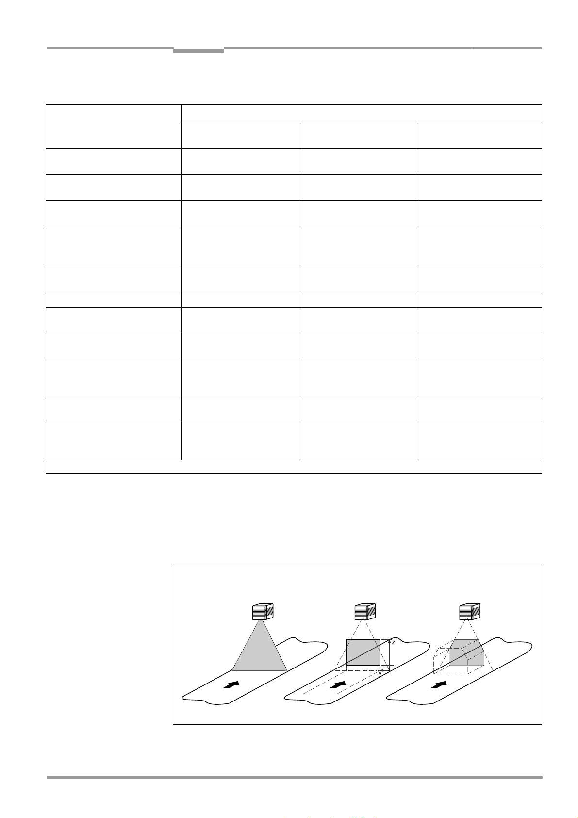
Operating Instructions Chapter 6
CLV 490 Bar Code Scanner
Operation
Overview: Autofocus functions
Parameter Autofocus mode
Minimum distance Differential background Differential background
and tracking
Condition Only one object in the reading
field during reading interval
1. Limitation values:
autofocus limitation
2. Limitation values:
scan angle limitation
Oscillating mirror:
3. Limitation values:
oscillating angle limitation
4. Limitation values:
autofocus space
5. Teach-in background – ❍❍
6. Scanner position parameters:
angle alpha, beta, gamma
7. Scanner position parameters:
coordinates x, y, z
8. Tracking:
Configure the mode
(OTS trigger or internal tracking)
9. Tracking parameters:
Focus release point
10.More than on bar code
per object:
Min. and max. number of codes
✖
: required ❍: optional –: not required
Table 6-7: Configuring the autofocus function (part 2)
✖❍❍
✖❍❍
✖✖✖
– ❍❍
– ✖✖
– ✖✖
––✖
––✖
––✖
Only one object in the reading
field during reading interval
Serveral objects in the reading
field during reading interval
Fig. 6-3 shows a 3D example of how the autofocus area of the CLV is adjusted using the
parameters "Limit values: scan angle limitation" and "Limit value: autofocus space".
Note If the required focus positions determined by the CLV are outside the defined autofocus
area limits, the focus positions are not switched over (not even to the limit values).
Autofocus spaceScan angle limitation
Fig. 6-3: Narrowing the autofocus range using limit values
8 009 993/O824/20-12-2004 © SICK AG · Division Auto Ident · Germany · All rights reserved 6-15
Result: Autofocus area
Page 94

Chapter 6 Operating Instructions
Operation
CLV 490 Bar Code Scanner
Event-controlled focus position switchover (alternative)
Event-controlled focus position switchover can be used if the autofocus function does not
provide the expected accuracy for the application. Event-controlled focus position
switchover is required in the following cases, for example:
• Conveyed material with a black surface (e.g. vehicle tires)
The laser light emitted by the CLV is absorbed by the surface of the material, which
means that the distance measurement may no longer be sufficiently accurate.
• Conveyed material with highly reflective surfaces (e.g. anti-static bags)
• Conveyed material with bar codes on the front edge in the conveying direction. At high
conveyor speeds, the CLV can no longer adjust the focus in time.
Action Settings in CLV-Setup
1. Set up distance
configurations
Ö READING CONFIGURATION tab
Ö READING AREA section
Ö DISTANCE CONFIGURATION button
Ö DISTANCE CONFIGURATION tab
– Focus position
Oscillating mirror:
– additionally: Oscillating mirror amplitude CW
Ö ASSIGNEMENT TABLE tab
– Index
– Valid configurations
To restrict the reading area for all valid distance configurations
proceed as described in Table 6-4, Page 6-11, CP limits
2. Select focus position
switchover (refered to the
start of the reading interval)
3. I
NPUTS/SERIAL trigger source:
select function for "IN 3"
and "IN 4" switching inputs
Ö READING CONFIGURATION tab
Ö FOCUS CONTROL sections
Ö INPUTS/SERIAL/AUTOFOCUS
– immediate or synchronous (default setting) or
– latched (special application)
Ö DEVICE CONFIGURATION tab
Ö ASSIGNMENT OF INPUTS section
Ö IN 3
–Focus control
Ö IN 4
–Focus control
Table 6-8: Guide: Configuring focus position switchover
Explanation Distance measurement
The distance measurement carried out by the CLV is independent of the focus control type.
It is used for automatic focus adjustment in autofocus mode and for determining the code
distance. For the distance measurement, the CLV determines a distance value for each
scan angle between –30° and +30° (line scanner) or between –25° and +25° (line scanner
with oscillating mirror). These distance values are used to create an up-to-date distance
profile between the min. and max. scan angle. Once mean value calculation has been
carried out, the distance profile is available after every 10th scan (e.g. every 10 ms at a
scanning frequency of 1,000 Hz). The distance measurement is carried out inside the limits
of 400 to 2,200 mm (15.8 to 86.7 in). If an object is being conveyed, the CLV determines
(with reading from above) an average object profile according to the conveyor speed. At
1,000 Hz and a speed of 2 m/s (6.6 ft/s), this occurs over a path of 20 mm (0.79 in) for
each object.
The angular resolution of the periodic distance measurement is 1.5° in the scanning
direction without an active median filter, and the typical distance measurement uncertainty
6-16 © SICK AG · Division Auto Ident · Germany · All rights reserved 8 009 993/O824/20-12-2004
Page 95

Operating Instructions Chapter 6
CLV 490 Bar Code Scanner
Operation
is ±50 mm (1.97 in). The median filter smoothes the values in the distance profile. An
excessively high filter value reduces the angular resolution of the CLV: at the maximum
reading distance, it may no longer be able to detect small objects or parts of objects. The
minimum object width at the maximum focus position is the key factor for determining the
filter length setting. The required reflectance of the objects is at least 12% in the
measurement range from 700 to 1,300 mm (27.6 to 51.2 in) and at least 20% in the
measurement range from 400 to 2,000 mm (15.8 to 86.7 in).
The CLV references the distance measurement with every reading pulse (in every search
interval with the "Object polling" reading pulse mode). With reading pauses > 6 minutes, the
CLV carries out referencing at regular intervals. To do so, it switches on the laser diode for
max. 10 seconds.
The autofocus function requires active distance measurement, although this is not a
requirement for event-controlled focus position switchover. In this case, however, the CLV
can output the actual code distance instead of the current focus position in the "Code Info/
Separator" block. The CLV measures the code distance in the area between the start and
stop character of a detected bar code and checks the distance against the parameterized
autofocus limits (the autofocus limit is output if the parameterized limits are violated). If the
distance measurement function is deactivated, the CLV first sets the parameterized
preferred focus position.
d) Parameterizing optical reading characteristics
• Scanning frequency Ö R
• Blank zone Ö R
EADING CONFIGURATION tab Ö READING PARAMETERS/START/STOP RATIO section
• Poor quality bar code print (e.g. small contrast or scattered print) Ö R
CONFIGURATION tab Ö CODE LABEL/BACKGROUND CHARACTERISTCS section
EADING CONFIGURATION tab Ö READING PARAMETERS section
EADING
• If reading bar codes with small height (bar lenght) using the SMART decoder Ö
C
ODE CONFIGURATION tab Ö DECODER section/SMART PARAMETERS button
8 009 993/O824/20-12-2004 © SICK AG · Division Auto Ident · Germany · All rights reserved 6-17
Page 96

Chapter 6 Operating Instructions
Operation
CLV 490 Bar Code Scanner
e) Parameterizing oscillation mirror functions (optional)
Action Settings in CLV-Setup
1. Choose "Oscillating with fixed amplitude"
mode
(identical amplitude for all distance
configurations with event-controlled focus
control)
– or –
2. Choose "Oscillating with variable amplitude"
mode
(amplitude can be chosen for each distance
configuration with event-controlled focus
control)
– or –
3. Choose "Fixed Position" mode
Ö OSCILLATING MIRROR tab
Ö OSCILLATING MIRROR section
– Oscillating with fixed amplitude
Ö OSCILLATING section
– Frequency
Ö OSCILLATING MIRROR tab
Ö OSCILLATING MIRROR section
– Oscillating with variable amplitude
Ö OSCILLATING MODE section
– Frequency
Ö READING CONFIGURATION tab
Ö AUTOFOCUS PARAMETERS button respectively
Distance Configurations
– Oscillating mirror amplitude CW
Ö OSCILLATING MIRROR tab
Ö OSCILLATING MIRROR section
– or –
– Fixed Position
Ö FIXED POSITION section
– Stationary Position (CW)
4. Choose "One-Shot" mode
Ö OSCILLATING MIRROR tab
Ö OSCILLATING MIRROR section
–One-Shot
Ö ONE-SHOT section
Ö PHASE 1
– Mirror Speed
– Start Position (CW)
– Distance Configuration (no.)
Ö PHASE 2
– Mirror Speed
– Start Position (CW)
– Distance Configuration (no.)
5. With One-Shot: choose trigger source
Ö OSCILLATING MIRROR tab
Ö ONE-SHOT section
Ö TRIGGER MODE
– Reading Trigger Pulse or
– Switching input or
– Serial interface
6. With One-Shot and trigger source "IN 3"
or "IN 4":
Choose function for switching input "IN 3"
or "IN 4"
Ö DEVICE CONFIGURATION tab
Ö ASSIGNMENT OF INPUTS
Ö IN 3
–One Shot or
Ö IN 4
–One Shot
Ö see also Table 5-29, Page 5-26
7. Choose activity of oscillating mode
"Oscillating with ..."
Ö OSCILLATING MIRROR tab
Ö OSCILLATING MIRROR ACITVE section
– Continuous or
– during reading interval
Table 6-9: Guide: Configuring oscillating mirror functions
6-18 © SICK AG · Division Auto Ident · Germany · All rights reserved 8 009 993/O824/20-12-2004
Page 97

Operating Instructions Chapter 6
CLV 490 Bar Code Scanner
Operation
Note The OSCILLATE WITH VARIABLE AMPILTUDE operating mode can only be selected from amplitudes
of min. ±10 CW and an oscillating frequency of 0.4 Hz or higher.
The scan line must always sweep the neutral position (CW = 50). This means that oscillation
is not possible in the range 60 CW to 80 CW, for example, but is possible in the range 40
CW to 80 CW.
Explanation of oscillating mirror functions
1. "Oscillating with fixed amplitude" mode
The oscillating mirror deflects the scan line up to the maximum angle of deflection of
±40 CW (corresponds to ±20°). Fig. 6-4 illustrates this mode when a bar code is read from
above.
Constant
oscillating
frequency
0 0
Scan line density depending on object height
Fig. 6-4: Oscillating mirror: "Oscillating with fixed amplitude" mode
2. "Oscillating with Variable Amplitude" mode
The deflection range can be parameterized separately for each of the maximum of 8
distance configurations/focus positions. The minimum/maximum values that can be set for
the deflection range for fast applications ensure that the scan line only sweeps areas that
contain bar codes during the time available. This also ensures that the scan line density on
the object is, for the most part, constant. Fig. 6-5 illustrates this mode when a bar code is
read from above.
8 009 993/O824/20-12-2004 © SICK AG · Division Auto Ident · Germany · All rights reserved 6-19
Page 98
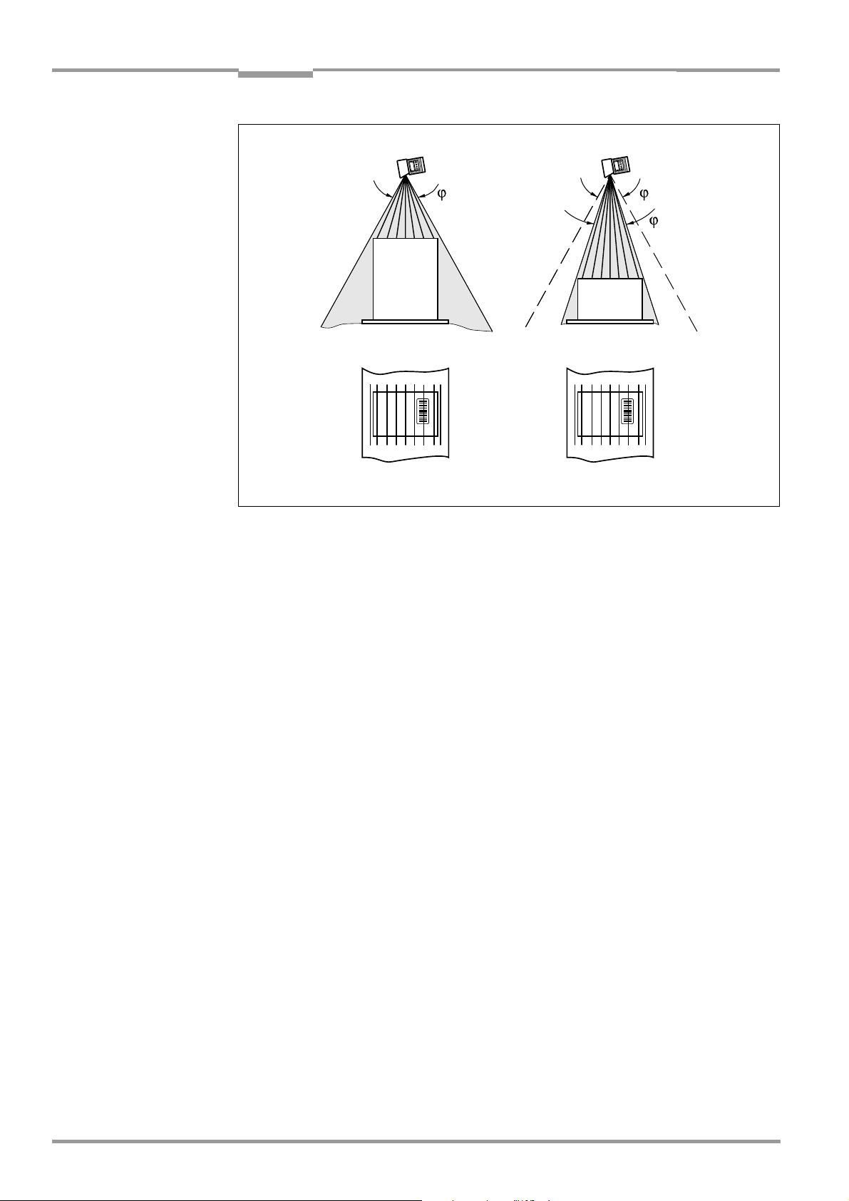
Chapter 6 Operating Instructions
Operation
CLV 490 Bar Code Scanner
Constant
oscillating
0 0
frequency
Scan line density equal, independant of object height
Fig. 6-5: Oscillating mirror: "Oscillating with variable amplitude" mode
Limitation of the
deflection range
(CW value)
1
3. "Fixed Position" mode
The CLV parks the oscillating mirror at the desired position. 10 CW corresponds to –20°,
and 90 CW to +20° (see Fig. 4-8, Page 4-6). In the default setting, the fixed position is set
to 50 CW (corresponds to an angle of deflection below 105°). The Oscillating mode is
switched off.
4. "One-Shot" mode
In the "One-Shot" mode, the oscillating mirror only performs one specific oscillating
movement per reading interval. This movement consists of a forward phase and a return
phase. The start position of the scan line, the mirror speed and the valid distance
configuration can be parameterized separately for each phase. The end position of the one
phase forms the start position of the other phase. Fig. 6-6 illustrates this mode with object
tracking. During the forward phase, the front of the object that moves towards the oscillating
mirror is swept once by the scan line from top to bottom in accordance with the conveyor
speed. Multiple focus position switchovers are not necessary as the required reading range
(DOF) is much smaller than with the line scanner. Fig. 10-42, Page 10-57 explains how the
start position and mirror speed are calculated for a given conveyor speed.
Possible trigger sources for One-Shot:
• "IN 3" or "IN 4" switching input
• Command string (via serial interface)
• Start of the reading interval
6-20 © SICK AG · Division Auto Ident · Germany · All rights reserved 8 009 993/O824/20-12-2004
Page 99

Operating Instructions Chapter 6
Operation
CLV 490 Bar Code Scanner
Conventionally required reading range
t
0
n
a
r
g
n
i
d
a
e
R
Reduced reading range through One-Shot function
t
1
e
g
n
a
r
g
n
i
d
a
e
R
Line scanner
e
g
Line scanner with
oscillating mirror
Fig. 6-6: One-Shot: Object tracking (bar code read from front)
8 009 993/O824/20-12-2004 © SICK AG · Division Auto Ident · Germany · All rights reserved 6-21
Page 100

Chapter 6 Operating Instructions
Operation
CLV 490 Bar Code Scanner
f) Parameterizing reading mode
The selected reading mode depends on the number of objects that are simultanously in the
reading field of the CLV during each reading interval. This is independent of the number of
bar codes on the actual object. Table 6-10 shows an overview of the configurations and
applications.
A. CLV in stand-alone configuration
Configuration Application See Page
A. Stand-alone Start/stop mode
• One object in reading field per reading interval, reading one side
Tracking mode (controlled by increment)
• Max. 10 objects in reading field per reading interval, reading one side, with
internal object tracking
B. Used in Omni Portal System
(arrangement with OTS 400
and other CLVs)
Start/stop modes
• One object in reading field per reading interval, CLV involved in reading one side
or more sides, master/slave arrangement with OTC 400 controller
Tracking mode (controlled by increment)
• Max. 20 objects in reading field per reading interval, CLV involved in reading one
side or more sides, with object tracking by the OTC 400 controller
6-22
6-28
6-31
6-34
Table 6-10: Overview: CLV applications in stand-alone configuration or in arrangement with OTS 400
A1. Start/stopp mode
• One object in the reading field per reading interval, reading one side
Possible reading triggers:
• One external sensor (e. g. photoelectric reflex switch)
• Two external sensors
• Command strings
• Free-running mode
• Object polling (Autofocus mode "Minimum distance“ or "Differential background")
Further preparations:
¾ Configuring reading area: see Chapter a)Parameterizing reading area, Page 6-10.
¾ Selecting focus control mode: see Chapter b) Selecting focus control mode,
Page 6-11.
¾ Configuring focus control: see Chapter c) Parameterizing focus control, Page 6-12.
¾ Configuring oscillating mirror (optional): see Chapter e) Parameterizing oscillation mirror
functions (optional), Page 6-18.
¾ Configuring no. of bar codes to be read: see Chapter h) Parameterizing the evaluation
characteristics, Page 6-37.
Note The size of the reading field is determined by the distance between the start and stop
sensors in conveying direction (see Fig. 3-5, Page 3-9). In object polling mode, the CLV
detects automatically an object entering or leaving the reading field.
To separate bar codes of the same type with identical contents, connect an incremental
encoder and activate the "Compare Code Position" function. See also Chapter Separation
of identical bar codes (same code type/identical contents), Page 6-37.
6-22 © SICK AG · Division Auto Ident · Germany · All rights reserved 8 009 993/O824/20-12-2004
 Loading...