

SICK CLV 45 Series, CLV 450-0010, CLV 451-0010, CLV 450-6010, CLV 451-6010 Operating Instructions Manual
Page 1
CLV 45x
Bar Code Scanner
NSTRUCTIONS
I
PERATING
O
Advanced line
Page 2

Software versions
Operating Instructions
CLV 45x Bar Code Scanner
Described software versions
Software/Tool Function Version
CLV 45x Firmware V 3.03 K949
CLV-Setup User interface (Windows-based) V 3.2 L547
CLV-Setup Help Online help (HTML) From V 1.1
I-ViewPro
TM
HTML browser (offline) From V 2.38
E-2
Windows 95
TM
98
, Windows NTTM, Windows XP
/
TM
and Internet-ExplorerTM are registered
TM
trademarks or trademarks of the Microsoft Corporation in the USA and other countries.
Netscape Navigator
TM
is a registered trademark of the Netscape Communications
Cooperation, USA.
I-View-Pro
©
SICK AG · Division Auto Ident · Germany · All rights reserved 8 009 139/K949/06-06-2002
TM
is a registered trademark of EnReach Technology, Inc., USA.
Page 3

Operating Instructions
CLV 45x Bar Code Scanner
Quick Finder
CLV 45x bar code scanner
Quick Finder
•
What is delivered with the device
Chapter 3.1.1 Scope of delivery, Page 3-1
–
•
Caution!
Chapter 2 Safety information, Page 2-1
–
•
Mounting the device at the reading station
Chapter 4 Installation, Page 4-1
–
•
Connecting the device
Chapter 5 Electrical installation, Page 5-1
–
•
Overview of the device and its functions
Chapter 3 Product description, Page 3-1
–
Chapter 6.2 Default setting, Page 6-1
–
Chapter 6.5 Operating modes and output of the read result, Page 6-18
–
Chapter 9 Technical data, Page 9-1
–
•
Starting the device with the default settings
Chapter 6.3 Quick-Start, Page 6-3
–
•
Installing the “CLV-Setup“ user software on the PC
Chapter 10.4 Installing and operating the "CLV-Setup" PC software, Page 10-20
–
•
Adapting the device to the reading application
Chapter 6.4 Configuration (parameterizing), Page 6-4
–
•
Help in cases of problems
Chapter 8 Troubleshooting, Page 8-1
–
•
Finding information
Table of contents, Page E-5
–
Chapter 10.16 Index, Page 10-66
–
8 009 139/K949/06-06-2002© SICK AG · Division Auto Ident · Germany · All rights reserved
E-3
Page 4

Quick Finder
Operating Instructions
CLV 45x Bar Code Scanner
Installation steps (overview)
Reading trigger via “Sensor 1“ switching input (default setting)
1. Check whether the delivery is complete.
2. Install the CLV in the reading station and align to the object with bar code.
3. Install the AMV/S 40 connection module and cover the terminal designations in the
connection area.
4. Connect the CLV to the AMV/S 40 connection module.
5. Install the reading-pulse sensor.
6. Connect the reading-pulse sensor to the "Sensor 1" switching input in the AMV/S 40.
7. Install the sensor for the distance detection.
8. Connect the distance sensor to the "Sensor 2" switching input in the AMV/S 40.
9. Connect the host to the "Host interface" in the AMV/S 40.
Adapt the AMV/S 40 to the host interface type of the CLV.
10. Switch on the supply voltage of the AMV/S 40.
After the CLV has been started the "Device Ready" LED lights up. The beeper signals
that Reading mode has been started by means of two consecutive sounds.
Line scanner with oscillating mirror:
In reading mode the CLV deflects the scan line in the default setting with a frequency of
1 Hz around the position CW = 50 at a maximum angle of ±20°.
11. Switch on the PC and start Windows
12. Install the supplied "CLV-Setup" user software, "CLV-Setup Help" online help and, if re-
quired, "I-ViewPro
TM
" HTML browser from the CD-ROM on the PC.
13. Connect the PC to the terminal interface of the CLV.
To this purpose connect the PC via the RS-232 data connection cable to the "Service"
plug in the AMV/S 40.
14. Start the "CLV-Setup" software.
CLV-Setup starts the communication with the CLV and copies the parameter record of
the CLV by means of an upload. The parameter record is displayed in the tab cards.
15. Carry out a test read run with a test bar code specimen (pulse the CLV correspondingly).
Display the read result in the terminal emulator of CLV-Setup.
16. Configure the CLV for the application by means of the setting options on the tab cards
in CLV-Setup.
Copy the modified parameter record temporarily to the CLV per download.
Do not
switch off the supply voltage of the AMV/S 40 (of the CLV).
17. Test the application under real conditions.
18. Check the correct data transfer of the CLV to the host.
19. If necessary, correct and optimize the set parameter values.
Copy the parameter record
permanently
20. Save the parameter record as a configuration file "*.scl" in CLV-Setup!
TM
(minimum requirement Windows 95TM).
to the CLV per download.
E-4
The CLV is ready to operate with the
©
SICK AG · Division Auto Ident · Germany · All rights reserved 8 009 139/K949/06-06-2002
application-specific
setting.
Page 5

Operating Instructions
CLV 45x Bar Code Scanner
Contents
Table of contents
1 Notes on this document .............................................................................................. 1-1
1.1 Function.......................................................................................................................................... 1-1
1.2 Target audience .......................................................................................................................... 1-1
1.2.1 Installation, electrical installation, maintenance, device replacement............ 1-1
1.2.2 Startup, operation and configuration .......................................................................... 1-1
1.3 Information content ................................................................................................................... 1-1
1.4 Symbols used .............................................................................................................................. 1-2
2 Safety information ......................................................................................................... 2-1
2.1 Authorized users ......................................................................................................................... 2-1
2.1.1 Installation and maintenance......................................................................................... 2-1
2.1.2 Electrical installation and replacing devices............................................................. 2-1
2.1.3 Startup, operation and configuration .......................................................................... 2-1
2.2 Intended use ................................................................................................................................ 2-1
2.3 General safety instructions and protective measures ................................................. 2-1
2.4 Quick Stop and Quick Restart ................................................................................................ 2-3
2.4.1 Switching off the CLV ........................................................................................................ 2-3
2.4.2 Switching on the CLV again ............................................................................................ 2-3
2.5 Environmental information ...................................................................................................... 2-4
2.5.1 Power requirement ............................................................................................................ 2-4
2.5.2 Disposal after final removal from service.................................................................. 2-4
3 Product description....................................................................................................... 3-1
3.1 Design ............................................................................................................................................. 3-1
3.1.1 Scope of delivery................................................................................................................ 3-1
3.1.2 Device variants.................................................................................................................... 3-1
3.1.3 System requirements ....................................................................................................... 3-1
3.1.4 Design line scanner ........................................................................................................... 3-3
3.1.5 Design line scanner with oscillating mirror................................................................ 3-4
3.2 Working method of the device .............................................................................................. 3-5
3.2.1 Changeable focal position............................................................................................... 3-6
3.2.2 Variants of the scanning process................................................................................. 3-6
3.3 Display and operating elements........................................................................................... 3-7
3.3.1 Operating elements ........................................................................................................... 3-7
3.3.2 Function of the LEDs ......................................................................................................... 3-7
3.3.3 Function of the beeper (buzzer) ................................................................................... 3-9
4 Installation ....................................................................................................................... 4-1
4.1 Overview of the installation steps ........................................................................................ 4-1
4.2 Preparations for installation .................................................................................................... 4-1
4.2.1 Laying out the components to be installed ready ................................................. 4-1
4.2.2 Laying out the accessories ready ................................................................................ 4-1
4.2.3 Laying out the required tools ready............................................................................. 4-1
4.2.4 Replacing the laser warning label................................................................................. 4-2
4.2.5 Selecting the installation site ......................................................................................... 4-2
4.2.6 Mounting accessories.......................................................................................................4-3
4.2.7 Distance between the CLV and the bar code ......................................................... 4-4
4.2.8 Counting direction of the code position CP and of the code angle CW ........ 4-6
4.3 Installation and adjustment of the device ......................................................................... 4-8
4.3.1 Installing the CLV ................................................................................................................ 4-8
4.3.2 Adjusting the CLV................................................................................................................ 4-8
4.3.3 Auxiliary functions for adjusting ...................................................................................4-10
4.4 Installing the external components....................................................................................4-11
4.4.1 Installing the AMV/S 40 connection module .........................................................4-11
4.4.2 Installing an external reading-pulse sensor............................................................4-12
4.4.3 Mounting the sensor for detecting the object distance ....................................4-13
4.5 Disassembling the device .....................................................................................................4-14
8 009 139/K949/06-06-2002© SICK AG · Division Auto Ident · Germany · All rights reserved
E-5
Page 6

Contents
Operating Instructions
CLV 45x Bar Code Scanner
5 Electrical installation.................................................................................................... 5-1
5.1 Overview of the installation step ...........................................................................................5-1
5.2 Electrical connections and cables ........................................................................................5-1
5.2.1 Connections/Cables when the AMV/S 40 connection module is used ........ 5-1
5.3 Pin assignment of the connecting plug............................................................................... 5-2
5.4 Preparation of the electrical installation ............................................................................. 5-2
5.4.1 Requirements for the host interface ........................................................................... 5-2
5.4.2 Supply voltage......................................................................................................................5-3
5.4.3 Non-SICK supply system device/wiring without SICK connection module...5-3
5.5 Carrying out the electrical installation..................................................................................5-4
5.5.1 Overview of the connection steps................................................................................5-4
5.5.2 Aids........................................................................................................................................... 5-4
5.5.3 Connecting the supply voltage.......................................................................................5-4
5.5.4 Wiring the host interface ..................................................................................................5-5
5.5.5 Connecting the CAN interface........................................................................................5-6
5.5.6 Connecting the PC ..............................................................................................................5-6
5.5.7 Wiring the "Sensor 1" switching input .......................................................................5-7
5.5.8 Wiring the "Sensor 2" switching input......................................................................... 5-8
5.5.9 Wiring the "Result 1" and "Result 2" switching outputs ......................................5-9
6 Operation.......................................................................................................................... 6-1
6.1 Overview of the startup steps ................................................................................................6-1
6.2 Default setting ..............................................................................................................................6-1
6.2.1 Default setting of line scanner ....................................................................................... 6-2
6.2.2 Default setting of line scanner with oscillating mirror............................................ 6-2
6.3 Quick-Start ..................................................................................................................................... 6-3
6.3.1 Starting up the line scanner/line scanner with oscillating mirror
with the factory default setting ...................................................................................... 6-3
6.4 Configuration (parameterizing)...............................................................................................6-4
6.4.1 Configuring the CLV by means of the CLV-Setup user interface ......................6-4
6.4.2 Function of the tab cards in CLV-Setup (overview) ............................................... 6-6
6.4.3 Guide to parameterization............................................................................................... 6-8
6.4.4 Configuring the CLV with Auto Setup........................................................................ 6-14
6.5 Operating modes and output of the read result .......................................................... 6-18
6.5.1 Reading mode (Standard mode) ............................................................................... 6-18
6.5.2 Percentage evaluation ...................................................................................................6-21
6.5.3 Adjusting mode ................................................................................................................. 6-23
6.5.4 Show CP limits................................................................................................................... 6-23
6.5.5 Displaying and editing operating data...................................................................... 6-25
6.5.6 Reading diagnosis............................................................................................................ 6-25
6.5.7 Host interface monitoring ............................................................................................. 6-26
6.5.8 Auxiliary input..................................................................................................................... 6-28
6.5.9 Self-test................................................................................................................................ 6-28
6.5.10 Carrying out device functions of the CLV in the dialog box ............................. 6-29
6.6 Messages of the CLV ............................................................................................................. 6-30
6.6.1 Displaying messages...................................................................................................... 6-30
6.6.2 System messages........................................................................................................... 6-30
6.6.3 Warnings.............................................................................................................................. 6-30
6.6.4 Error messages ................................................................................................................ 6-30
6.7 Switching off the CLV..............................................................................................................6-31
7 Maintenance ................................................................................................................... 7-1
7.1 Maintenance during operation...............................................................................................7-1
7.2 Maintenance ................................................................................................................................. 7-2
7.3 Disposal .......................................................................................................................................... 7-2
8 Troubleshooting ............................................................................................................. 8-1
8.1 Overview of the possible errors and malfunctions.........................................................8-1
E-6
©
SICK AG · Division Auto Ident · Germany · All rights reserved 8 009 139/K949/06-06-2002
Page 7

Operating Instructions
CLV 45x Bar Code Scanner
Contents
8.1.1 Mounting errors................................................................................................................... 8-1
8.1.2 Faults during the electrical installation ....................................................................... 8-1
8.1.3 Parameterization errors ................................................................................................... 8-1
8.1.4 Faults during operation ....................................................................................................8-1
8.2 Monitoring error and fault signs ............................................................................................ 8-1
8.3 Error messages ........................................................................................................................... 8-2
8.4 ST error status in the read result of a bar code ............................................................. 8-5
8.5 Troubleshooting........................................................................................................................... 8-6
8.5.1 General malfunctions: CLV not ready ......................................................................... 8-6
8.5.2 Malfunction in Reading mode: Reading pulsing errors ........................................ 8-7
8.5.3 Malfunctions in Reading mode: Result output errors ........................................... 8-9
8.5.4 Malfunctions in Reading mode: Errors in the result status output ................8-12
8.5.5 Malfunctions in Reading mode: Oscillating mirror operation errors ..............8-13
8.5.6 Malfunctions: Configuration errors (parameterization) ......................................8-14
8.6 SICK Support..............................................................................................................................8-14
9 Technical data ................................................................................................................ 9-1
9.1 Data sheet CLV 45x line scanner ....................................................................................... 9-1
9.2 Data sheet CLV 45x line scanner with oscillating mirror............................................. 9-2
9.3 Dimensional drawings CLV...................................................................................................... 9-3
9.3.1 Line scanner......................................................................................................................... 9-3
9.3.2 Line scanner with oscillating mirror ............................................................................. 9-4
10 Appendix........................................................................................................................ 10-1
10.1 Appendix overview ...................................................................................................................10-1
10.2 Specification diagrams ...........................................................................................................10-2
10.2.1 Reading conditions for all diagrams ..........................................................................10-2
10.2.2 Overview of diagrams .....................................................................................................10-2
10.2.3 Reading ranges of CLV 450 line scanner/line scanner with
oscillating mirror ................................................................................................................10-3
10.2.4 Depths of field for CLV 450 line scanner (front-end reading window) ........10-5
10.2.5 Depths of field for CLV 450 line scanner with oscillating mirror
(side-end reading window)............................................................................................10-9
10.2.6 Depths of field for CLV 451 line scanner (front-end reading window) .....10-13
10.2.7 Depths of field for CLV 451 line scanner with oscillating mirror
(side-end reading window).........................................................................................10-15
10.2.8 Characteristics field scanning frequency (maximum values) .......................10-17
10.2.9 Deflection range of CLV 450 line scanner with oscillating mirror...............10-18
10.2.10 Deflection range of CLV 451 line scanner with oscillating mirror ...............10-18
10.3 System messages.................................................................................................................10-19
10.4 Installing and operating the "CLV-Setup" PC software............................................10-20
10.4.1 Preparing the installation ............................................................................................10-20
10.4.2 Carrying out the installation .......................................................................................10-20
10.4.3 Starting "CLV-Setup"....................................................................................................10-22
10.4.4 CLV-Setup user interface ...........................................................................................10-24
10.4.5 Functions ..........................................................................................................................10-25
10.4.6 "CLV-Setup Help" online help ...................................................................................10-25
10.4.7 Transferring a parameter record between CLV-Setup and the CLV..........10-26
10.4.8 Handling unknown parameters ................................................................................10-26
10.4.9 Recording the log file in the terminal emulator ..................................................10-27
10.4.10 Starting CLV-Setup with an INI file as an argument .........................................10-27
10.4.11 CLV Assistant ..................................................................................................................10-27
10.5 Configuring the CLV by means of Profile bar codes.................................................10-28
10.5.1 Activate Auto Setup with Profile bar code............................................................10-28
10.5.2 Profile progamming.......................................................................................................10-30
10.6 Configuring the CLV with command strings .................................................................10-33
10.7 Calculating parameter values for setting the CLV.....................................................10-35
10.7.1 Calculating the number of scans (for standard decoders) ...........................10-35
10.7.2 Calculating the start position and mirror speed for the forward
8 009 139/K949/06-06-2002© SICK AG · Division Auto Ident · Germany · All rights reserved
E-7
Page 8

Contents
Operating Instructions
CLV 45x Bar Code Scanner
and return phase of the One-Shot function........................................................ 10-37
10.7.3 Calculating the necessary distance if several bar codes are
read on each object..................................................................................................... 10-38
10.8 Auxiliary tables........................................................................................................................ 10-39
10.8.1 Calculating the code length of a bar code .......................................................... 10-39
10.9 Special applications and procedures ............................................................................ 10-40
10.9.1 Triggering the Teach-in match code 1 via the "Sensor 2"
switching input................................................................................................................ 10-40
10.9.2 Auxiliary input via terminal interface....................................................................... 10-45
10.9.3 "Building a Daisy-chain configuration"
(data forwarding or master/slave arrangement) .............................................. 10-48
10.9.4 SICK network (RS 485) .............................................................................................. 10-48
10.9.5 Connection to the Profibus DP................................................................................. 10-48
10.9.6 Connection to the DeviceNet................................................................................... 10-48
10.9.7 Connection to the Interbus-S ................................................................................... 10-48
10.9.8 Connection to Ethernet............................................................................................... 10-49
10.9.9 Building a CAN Scanner Network............................................................................ 10-49
10.10 Replacing a CLV (copying the parameter record) .................................................... 10-49
10.10.1 Transferring the parameter set using Profile bar codes................................ 10-49
10.10.2 Transferring the parameter record by means of a download...................... 10-50
10.11 Available accessories .......................................................................................................... 10-51
10.11.1 Mounting accessories................................................................................................. 10-51
10.11.2 Connection modules.................................................................................................... 10-51
10.11.3 Bus connection modules ........................................................................................... 10-52
10.11.4 Cables and connectors............................................................................................... 10-52
10.11.5 Reading pulse generation.......................................................................................... 10-53
10.11.6 Network controller ........................................................................................................ 10-53
10.12 Dimensioned drawings of the accessories ................................................................. 10-54
10.12.1 Mounting bracket No. 2 020 410 (for one CLV) ........................................... 10-54
10.12.2 Mounting bracket No. 2 022 564.......................................................................... 10-54
10.12.3 Rod clamp No. 2 023 691 ....................................................................................... 10-55
10.12.4 Mounting bracket with vibration damper No. 2 031 342............................. 10-55
10.13 Supplementary documentation ....................................................................................... 10-56
10.14 Glossary.................................................................................................................................... 10-57
10.15 Copy of the EC Declaration of Conformity................................................................... 10-64
10.17 Bar code sample................................................................................................................... 10-69
E-8
©
SICK AG · Division Auto Ident · Germany · All rights reserved 8 009 139/K949/06-06-2002
Page 9

Operating Instructions
CLV 45x Bar Code Scanner
Figures and tables
Abbreviations used
DC D
AMV/S
BMV/S
CAN C
CLV
DOF D
EEPROM E
HTML H
LED
RAM R
ROM R
RTF R
PLC P
SMART S
istance Configuration
Connection module with distributor (signal)/with additional power supply
Bus connection module with distributor (signal)/with additional power supply
ontroller Area Network (standard field bus system with message-orientated data exchange protocol)
Code reader V principle. The bar code scanner CLV 45x is designated for all the types
simply as a "CLV", except at text positions where a differentiation is required.
epth Of Field
lectrically Erasable Programmable Read Only Memory
yper Text Markup Language (page description language in Internet)
L
ight Emitting Diode
andom Access Memory
ead Only Memory
ich Text Format (standardized document format with format descriptions)
rogrammable Logic Controller
ICK Modular Advanced Recognition Technology
Tables
Table 3-1: Variants of the CLV 45x ..................................................................................................3-1
Table 3-2: Meaning of the LEDs........................................................................................................3-8
Table 3-3: Function of the beeper....................................................................................................3-9
Table 4-1: Permitted reading angle between the scan line and the bar code ................4-5
Table 5-1: Pin assignment of the 15-pin D-Sub HD cable plug ............................................5-2
Table 5-2: Maximum cables lengths between the CLV and the host ................................. 5-2
Table 5-3: Power consumption of the CLV....................................................................................5-3
Table 5-4: Power-up delay as a function of the device number GN ...................................5-3
Table 5-5: Wire color assignment of cable No. 6 010 137 (open end) .........................5-4
Table 5-6: Communication parameters of the host interface (default setting)............... 5-5
Table 5-7: Characteristic data of the "Sensor 1" switching input ........................................5-7
Table 5-8: Focal position changeover: Assignment table switching input –
distance configuration......................................................................................................5-9
Table 5-9: Characteristic data of the switching outputs "Result 1" and "Result 2" ...5-10
Table 6-1: Extract: Default setting of the line scanner parameter values.........................6-2
Table 6-2: Extract: Default setting of additional parameter values of the
line scanner with oscillating mirror..............................................................................6-2
Table 6-3: Reading distances of CLV 450 and CLV 451 (default) for quick start .........6-4
Table 6-4: Guide: Parameterizing the changeover of the distance configuration/
focal position ....................................................................................................................... 6-8
Table 6-5: Guide: Parameterizing the oscillating reading mirror functions........................ 6-9
Table 6-6: Guide: Parameterizing the reading pulse source ...............................................6-12
Table 6-7: Guide: Parameterizing the laser timeout ...............................................................6-12
Table 6-8: Guide: Settings to be carried out for evaluating identical bar codes .........6-13
Table 6-9: "Host interface monitoring" function....................................................................... 6-26
Table 6-10: Warning............................................................................................................................... 6-30
Table 8-1: Error messages output via the terminal interface ................................................8-2
Table 8-2: Meaning of the ST error status in the read result.................................................8-5
Table 8-3: Troubleshooting: Restoring operation (Reading mode)......................................8-6
Table 8-4: Troubleshooting: Reading pulsing errors in Reading mode...............................8-7
Table 8-5: Troubleshooting: Result output errors in Reading mode.................................... 8-9
Table 8-6: Troubleshooting: Errors in the result status output in Reading mode........ 8-12
8 009 139/K949/06-06-2002© SICK AG · Division Auto Ident · Germany · All rights reserved
E-9
Page 10

Figures and tables
Table 8-7: Troubleshooting: Oscillating mirror errors in Reading mode...........................8-13
Table 8-8: Troubleshooting: Configuration errors (parameterization) ..............................8-14
Table 9-1: Technical specifications line scanner........................................................................ 9-1
Table 9-2: Technical specifications line scanner with oscillating mirror............................. 9-2
Table 10-1: Reading conditions for specification diagrams ....................................................10-2
Table 10-2: Overview CLV 45x specification diagrams ............................................................10-2
Table 10-3: CLV 450: Optimum of scanning frequencies ....................................................10-17
Table 10-4: CLV system messages ..............................................................................................10-19
Table 10-5: Default settings of CLV-Setup (extract) ...............................................................10-22
Table 10-6: Function of the preprinted Profile bar codes on card No. 8 008 085....10-33
Table 10-7: Auxiliary table for calculating the code length of a bar code.......................10-39
Table 10-8: Communication parameters to be set on the terminal/PC for the
auxiliary input .................................................................................................................10-47
Table 10-9: Communication parameter to be set for the ST 1100 decoder...............10-48
Table 10-10: Available accessories: Mounting accessories ..................................................10-51
Table 10-11: Available accessories: Connection modules.....................................................10-51
Table 10-12: Accessories: Bus Connection modules...............................................................10-52
Table 10-13: Available accessories: Cables and connectors................................................10-52
Table 10-14: Available accessories: Network controller..........................................................10-53
Table 10-15: Supplementary documentation in English..........................................................10-56
Operating Instructions
CLV 45x Bar Code Scanner
Figures
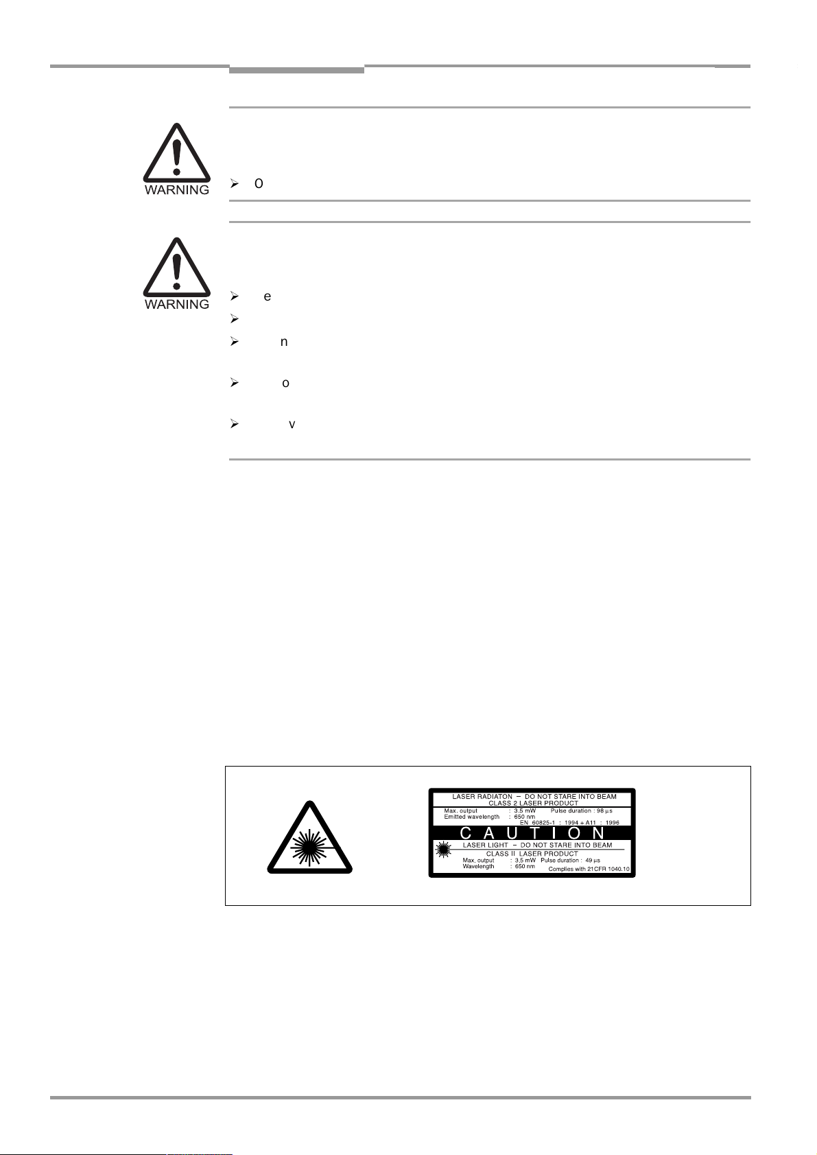
Fig. 2-1: Laser warning label attached to the CLV (valid for Europe)................................. 2-2
Fig. 3-1: Design of the line scanner CLV 45x.............................................................................. 3-3
Fig. 3-2: Design of the line scanner with oscillating mirror CLV 45x .................................. 3-4
Fig. 3-3: Block diagram: Functions of the CLV ............................................................................ 3-5
Fig. 3-4: Focal position changeover: Division of the overall reading range into
distance configurations ...................................................................................................... 3-6
Fig. 3-5: Oscillating mirror: Example of the focal position changeover in the
search run ............................................................................................................................... 3-7
Fig. 3-6: LEDs .......................................................................................................................................... 3-8
Fig. 4-1: Example of line scanner: Exchanging the laser warning label............................. 4-2
Fig. 4-2: Example of line scanner: Position of the fastening thread at the CLV ............. 4-3
Fig. 4-3: Line scanner: Example of the mounting possibilities of the CLV with the
mounting bracket No. 2 020 410 ................................................................................. 4-3
Fig. 4-4: Line scanner: Example of the mounting possibilities of the CLV with the
mounting bracket No. 2 022 564 ................................................................................. 4-4
Fig. 4-5: Positioning of the scanning process to the bar code and to the conveyor
direction ................................................................................................................................... 4-4
Fig. 4-6: Definition of the reading distance a and of the aperture angle a...................... 4-5
Fig. 4-7: Line scanner: Reading angle occurring between the scan line and
the bar code........................................................................................................................... 4-5
Fig. 4-8: Avoiding surface reflections: Angle between the emitted light and
the bar code (tilted away from the perpendicular) .................................................. 4-6
Fig. 4-9: Counting direction of the code position CP within the scan line and
of the code angle CW at an oscillating mirror............................................................ 4-7
Fig. 4-10: Line scanner: Appearance of the scan line in the "Adjusting mode"
operating mode...................................................................................................................4-10
Fig. 4-11: Correction of the printed terminal assignment in the connection area
of the AMV/S 40.................................................................................................................4-11
Fig. 4-12: Line scanner: Installation example for positioning the external
reading-pulse sensor ........................................................................................................4-12
Fig. 4-13: CLV 44x: Installation example for positioning the object distance
detection................................................................................................................................4-13
Fig. 5-1: Block diagram: Connection of the CLV to the AMV/S 40 connection
module...................................................................................................................................... 5-1
E-10
©
SICK AG · Division Auto Ident · Germany · All rights reserved 8 009 139/K949/06-06-2002
Page 11

Operating Instructions
CLV 45x Bar Code Scanner
Figures and tables
Fig. 5-2: Wiring the host interface .................................................................................................... 5-5
Fig. 5-3: Wiring the terminal interface ............................................................................................. 5-6
Fig. 5-4: Wiring of the "Sensor 1" switching input......................................................................5-7
Fig. 5-5: Wiring of the "Sensor 2" switching input......................................................................5-8
Fig. 5-6: Wiring of the "Result 1" switching output ....................................................................5-9
Fig. 6-1: Bar code patter for CLV 450 (Code 39; module width 0.35 mm;
Print ratio 2:1) ........................................................................................................................6-3
Fig. 6-2: Bar code patter for CLV 451 (Code 39; module width 0.5 mm;
Print ratio 2:1) ........................................................................................................................6-4
Fig. 6-3: "Oscillating with fixed amplitude" operating mode................................................ 6-10
Fig. 6-4: "Oscillating with variable amplitude" operating mode .........................................6-10
Fig. 6-5: One-Shot: Object tracking (bar code read from front)......................................... 6-11
Fig. 6-6: CLV-Setup: Displaying the course of the Auto Setup in the
terminal emulator...............................................................................................................6-16
Fig. 6-7: CLV-Setup: Displaying the read result of the terminal interface in the
terminal emulator...............................................................................................................6-19
Fig. 6-8: Read result of the terminal interface: Structure for “Good Read“ .................. 6-20
Fig. 6-9: Read result of the terminal interface: Structure for “No Read“........................ 6-20
Fig. 6-10: CLV-Setup: Displaying the percentage evaluation in the
terminal emulator...............................................................................................................6-22
Fig. 6-11: Appearance of scan line in the "Show CP-limits" mode .....................................6-24
Fig. 6-12: CLV-Setup: "Operating Data" dialog box................................................................... 6-25
Fig. 6-13: CLV-Setup: Output of the read result of the host interface in the terminal
emulator at the beginning (in this case: O = Output)........................................... 6-27
Fig. 6-14: CLV-Setup: Outputting the self-test result in the terminal emulator............... 6-28
Fig. 6-15: CLV-Setup: Dialog box for executing the Auto Setup...........................................6-29
Fig. 7-1: Cleaning the reading window............................................................................................7-1
Fig. 7-2: Cleaning the external optical sensors (reading clock generator,
object height detection)......................................................................................................7-2
Fig. 9-1: Dimensions of the line scanner .......................................................................................9-3
Fig. 9-2: Dimensions of the line scanner with oscillating mirror ........................................... 9-4
Fig. 10-1: CLV 450-0010: Reading ranges about all focal positions for line scanner 10-3
Fig. 10-2: CLV 450-6010: Reading ranges about all focal positions for line
scanner with oscillating mirror....................................................................................... 10-4
Fig. 10-3: CLV 450-0010: Min. and max. reading distance for the line scanner as a
function of the focal position at a resolution of 0.25 mm..................................10-5
Fig. 10-4: CLV 450-0010: Min. and max. reading distance for the line scanner as a
function of the focal position at a resolution of 0.35 mm..................................10-6
Fig. 10-5: CLV 450-0010: Min. and max. reading distance for the line scanner as a
function of the focal position at a resolution of 0.50 mm..................................10-7
Fig. 10-6: CLV 450-0010: Min. and max. reading distance for the line scanner as a
function of the focal position at a resolution of 1.00 mm..................................10-8
Fig. 10-7: CLV 450-6010: Min. and max. reading distance for the line scanner with
oscillating mirror as a function of the focal position at a resolution
of 0.25 mm ..........................................................................................................................10-9
Fig. 10-8: CLV 450-6010: Min. and max. reading distance for the line scanner with
oscillating mirror as a function of the focal position at a resolution
of 0.35 mm .......................................................................................................................10-10
Fig. 10-9: CLV 450-6010: Min. and max. reading distance for the line scanner with
oscillating mirror as a function of the focal position at a resolution
of 0.50 mm .......................................................................................................................10-11
Fig. 10-10: CLV 450-6010: Min. and max. reading distance for the line scanner with
oscillating mirror as a function of the focal position at a resolution
of 1.00 mm .......................................................................................................................10-12
Fig. 10-11: CLV 451-0010: Min. and max. reading distance for the line scanner
as a function of the focal position and the tilt at a resolution of 0.5 mm
and an aperture angle of 25• ................................................................................... 10-13
Fig. 10-12: CLV 451-0010: Min. and max. reading distance for the line scanner
8 009 139/K949/06-06-2002© SICK AG · Division Auto Ident · Germany · All rights reserved
E-11
Page 12

Figures and tables
Operating Instructions
CLV 45x Bar Code Scanner
as a function of the focal position and the tilt at a resolution of 0.5 mm
and an aperture angle of 55• ....................................................................................10-14
Fig. 10-13: CLV 451-6010: Min. and max. reading distance for the line scanner
with oscillating mirror as a function of the focal position and the tilt at a
resolution of 0.5 mm and an aperture angle of 25• ........................................10-15
Fig. 10-14: CLV 451-6010: Min. and max. reading distance for the line scanner
with oscillating mirror as a function of the focal position and the tilt at a
resolution of 0.5 mm and an aperture angle of 55• ........................................10-16
Fig. 10-15: CLV 450: Characteristics field scanning frequency as a function of
the reading distance and resolution ........................................................................10-17
Fig. 10-16: CLV 450-6010: Deflection range as a function of the reading distance,
the angle of deflection and the resolution .............................................................10-18
Fig. 10-17: CLV 451-6010: Deflection range as a function of the reading distance
and the angle of deflection at a resolution of 0.5 mm .....................................10-18
Fig. 10-18: CLV-Setup: Result display of the AutoBaud-Detect ...........................................10-23
Fig. 10-19: User interface of the "CLV-Setup" software .........................................................10-24
Fig. 10-20: CLV-Setup: Entering commands in the terminal emulator ..............................10-34
Fig. 10-21: Line scanner: Calculating the number of scans for ladder-type bar code
positioning ..........................................................................................................................10-35
Fig. 10-22: Line scanner: Calculating the number of scans for fence-type bar code
positioning ..........................................................................................................................10-35
Fig. 10-23: Line scanner with oscillating mirror: Calculating the number of scans for
fence-type bar code positioning ................................................................................10-36
Fig. 10-24: One-Shot: Line scanner with oscillating mirror: Calculating the number
of scans for fence-type bar code positioning .......................................................10-37
Fig. 10-25: Required distance between the bar codes on an object.................................10-38
Fig. 10-26: Wiring of the "Sensor 2" switching input for triggering the teach-in
match code 1....................................................................................................................10-40
Fig. 10-27: Auxiliary input via the terminal interface of the CLV ...........................................10-46
Fig. 10-28: CLV-Setup: Auxiliary input on the terminal emulator..........................................10-47
Fig. 10-29: Dimensions of the mounting bracket No. 2 020 410 ......................................10-54
Fig. 10-30: Dimensions of the mounting bracket No. 2 022 564 ......................................10-54
Fig. 10-31: Dimensions of the rod clamp No. 2 023 691 .....................................................10-55
Fig. 10-32: Dimensions of the mounting bracket with vibration damper
No. 2 031 342.................................................................................................................10-55
Fig. 10-33: Reproduction of the declaration of conformity (Page 1, reduced in size) .10-64
Fig. 10-34: Reproduction of the declaration of conformity (Page 2, reduced in size) .10-65
Fig. 10-35: Scannable bar codes of various module widths (printing ratio 2:1)............10-69
E-12
©
SICK AG · Division Auto Ident · Germany · All rights reserved 8 009 139/K949/06-06-2002
Page 13

Operating Instructions Chapter 1
CLV 45x Bar Code Scanner
Notes on this document
1
Notes on this document
1.1 Function
This document instructs you on using the bar code scanner
•
CLV 450 with dynamic focal position adjustment
•
CLV 451 with dynamic focal position adjustment, optimized on 0.5 mm module width
in the variants
•
Line scanner
•
Line scanner with oscillating mirror
The document contains information on
•
Device installation and electrical installation
•
Startup
•
Operation and configuration (parameterization)
•
Maintenance
•
Device replacement with importing of the parameter record
•
Special applications and processes
The bar code scanners will all simply be called "CLV" below, except in such text passages
where a differentiation is required.
1.2 Target audience
Target audience for this document are persons with the following activities:
1.2.1 Installation, electrical installation, maintenance, device replacement
Electricians and service technicians
1.2.2 Startup, operation and configuration
Technicians and engineers
1.3 Information content
This document contains all the information required for the installation, electrical installation
and startup of the CLV with the default setting in our works.
All actions are described step-by-step.
The configuration of the CLV for the application-specific read situation is carried out with
the Windows-oriented "CLV-Setup" PC software and the "CLV Assistant". The "CLV-Setup
Help" online help system is available as an additional help. Installation of the software and
use of the user interface are described in the appendix.
Further information on the construction of the bar code scanner as well as the bar code
technology can be obtained from SICK AG, Auto Ident Division.
8 009 139/K949/06-06-2002© SICK AG · Division Auto Ident · Germany · All rights reserved
1-1
Page 14
Chapter 1 Operating Instructions
Notes on this document
CLV 45x Bar Code Scanner
1.4 Symbols used
Some information in this documentation is emphasized in order to facilitate rapid access to
this information:
Warning!
A "Warning" protects persons against injuries or the bar code scanner against serious damage.
¾
Always read warnings carefully and observe them exactly.
Note A "Note" informs on exceptional features.
Explanation An explanation provides background information on technical correlations.
Recommendation A "Recommendation" provides information on how to carry out an action optimally.
Hint A hint explains the setting possibilities in the user interface of the CLV-Setup.
Default setting Marks a section in which the values of the default setting of our works are listed.
CANNING FREQUENCY
S
This font characterizes a term used in the user interface of the CLV-Setup.
A symbol refers to a command button in the user interface of the CLV-Setup.
"Host receive fault"
This font characterizes messages which the CLV outputs via the terminal interface.
This symbol characterizes a section in which the steps for using the user interface of the
CLV-Setup are described.
This symbol characterizes a section in which the steps for using the profile programming are
described.
This symbol refers to supplementary technical documentation.
¾
Here you have to do something. This symbol characterizes single-step operating instructions. Multiple-step operating instructions are characterized by sequential numbers.
1-2
Ö
Here you select a function in the user interface of CLV-Setup.
©
SICK AG · Division Auto Ident · Germany · All rights reserved 8 009 139/K949/06-06-2002
Page 15

Operating Instructions Chapter 2
CLV 45x Bar Code Scanner
Safety information
2
Safety information
2.1 Authorized users
The CLV must be installed and operated by qualified personnel in order to ensure that it
functions correctly and safely.
The following qualifications are required for the various activities:
2.1.1 Installation and maintenance
•
•
2.1.2 Electrical installation and replacing devices
•
•
•
2.1.3 Startup, operation and configuration
•
•
•
•
•
•
Basic practical technical training
Knowledge of the common safety instructions at the workplace
Practical electrical training
Knowledge of the common electrical safety instructions
Knowledge of the operation and handling of the devices of the respective application
(e. g. transport unit)
Knowledge of the operation and handling of the devices of the respective application
(e. g. transport unit)
Knowledge of the software and hardware environment of the respective application
(e. g. transport unit)
A basic knowledge of Windows 95
TM
/98TM, Windows NT
Basic knowledge of a HTML browser, for example, Netscape Navigator
TM
or Windows XP
TM
TM
Basic knowledge of data transmission
Basic knowledge of bar code technology
2.2 Intended use
The CLV detects and decodes bar codes automatically. It is installed in a reading station and
reads, for example, bar codes on objects of a conveyor belt.
The CLV transfers the data contents of the decoded bar code via the host interface to a host
for further processing.
The user forfeits any warranty claims against SICK AG in case of any other use as well as in
case of changes to the device, also during device installation and electrical installation.
2.3 General safety instructions and protective measures
¾
Read the general safety instructions thoroughly and observe them strictly at all activities
at the CLV. Also observe the warnings before operating instructions in the individual
chapters of this document.
8 009 139/K949/06-06-2002© SICK AG · Division Auto Ident · Germany · All rights reserved
2-1
Page 16
Chapter 2 Operating Instructions
Safety information
CLV 45x Bar Code Scanner
Danger of injury through electrical current!
The AMS 40 connection module (accessory) for the CLV is connected to 230 V 50 Hz or
115 V AC 50/60 Hz supply voltage, depending on the type.
¾
Observe the common safety regulations when working on electrical installations.
Laser radiation may cause damage to your eyes!
The CLV operates with a Class 2 red-light laser. The retina can be damaged if you look
too long into the laser beam.
¾
Never look directly into the laser beam (comparable with sunlight).
¾
Do not point the laser beam at persons.
¾
When mounting and aligning the CLV take the reflection of the laser beam against reflecting surfaces into account.
¾
Do not open the housing.
(Opening does not interrupt activation of the laser diode by the reading pulsing.)
¾
Observe the laser protection specifications in accordance with DIN EN 60825-1 (latest
version).
Laser performance
The laser operates with a wavelength of λ= 650 nm (visible red light). The power output of
the laser beam amounts to a max. of 3.5 mW at the reading window.
The emitted radiation is not dangerous to the human skin.
Laser warning labels
The laser warning labels relevant for Europe (
Fig. 2-1
) are located at the following points at
the CLV:
•
At the line scanner the British/US version of the laser warning symbol and the laser
warning are located next to the front-end reading window on the side surface (refer to
Fig. 3-1, Page 3-3
•
At the line scanner with oscillating mirror the British/US version of the laser warning sym-
).
bol and the laser warning are located on the side surface opposite the reading window
(refer to
Fig. 3-2, Page 3-4
).
2-2
Fig. 2-1: Laser warning label attached to the CLV (valid for Europe)
Note The scope of delivery includes a set of laser warnings in German/US English and French/US
English. These can be stuck over the British/US warning.
If the CLV is installed in a machine/casing in such a manner that the laser warning
labels of the device is concealed, further warning labels (not included in the scope of
delivery) must be attached on the machine next to the aperture of the laser beam!
©
SICK AG · Auto Ident · Germany · All rights reserved 8 009 139/K949/06-06-2002
Page 17

Operating Instructions Chapter 2
CLV 45x Bar Code Scanner
Safety information
Internal protective circuits
The CLV has monitoring circuits which shut off the laser diode when irregularities occur in
the beam generation.
The switching on and off of the laser diode during the reading process is controlled by the
reading pulsing (pulse source).
In the pulsing types "Sensor input" and "Serial interface" a timer (laser timeout) switches off
the laser diode automatically 10 min (default setting) after the beginning of a lasting reading
pulse during reading mode. However it does not terminate the reading pulse. CLV outputs
the following message via the terminal interface:
"Laser safety timeout"
The reading pulse has to be terminated by means of a corresponding pulse signal. The next
reading pulse re-activates the laser diode.
The laser timeout can be set in the range of 1 min ... 25 h or de-activated (refer to
Table 6-7, Page 6-12
The laser diode is always active in reading mode in the operating modes "Percentage
evaluation", "Adjusting mode", "Show CP limits" and "Auto setup" as well as in the
"free-running" pulsing type.
).
2.4 Quick Stop and Quick Restart
2.4.1 Switching off the CLV
¾
Switch off the supply voltage or pull off the cable plug of the CLV from the connection
module.
At most the following may be lost:
•
The application-specific parameter record, if it was only saved temporarily in the CLV
•
The last reading result
•
Day operating data
(operating hours counter, trigger count, number of good reads, maximum duration
trigger, minimum duration trigger, average identification quality)
2.4.2 Switching on the CLV again
¾
Switch on the supply voltage or pin up again the cable plug of the CLV to the connection
module.
The CLV restarts operation with the parameter record last saved permanently and re-
sets the day operating data.
8 009 139/K949/06-06-2002© SICK AG · Division Auto Ident · Germany · All rights reserved
2-3
Page 18

Chapter 2 Operating Instructions
Safety information
CLV 45x Bar Code Scanner
2.5 Environmental information
The CLV is designed so that it harms the environment as little as possible. It does not have
any materials using silicone and is therefore not a source of faults for, for example, coating
wetting in paint shops.
2.5.1 Power requirement
The power requirement is low.
•
The line scanner consumes a max. of 6 W
•
The line scanner with oscillating mirror consumes a max. of 7.2 W
The values each correspond to operation with open-circuited switching outputs.
2.5.2 Disposal after final removal from service
Dispose of unusable or irreparable devices in accordance with the respective state regulations on waste disposal in a manner compatible with the environment. The design of the CLV
allows it to be separated into recyclable secondary raw materials and hazardous waste
(electronic scrap). Refer to
Chapter 7.3 Disposal, Page 7-2
.
At present SICK AG does not take back devices which have become unusable or
irreparable.
2-4
©
SICK AG · Auto Ident · Germany · All rights reserved 8 009 139/K949/06-06-2002
Page 19

Operating Instructions Chapter 3
CLV 45x Bar Code Scanner
Product description
3
Product description
3.1 Design
3.1.1 Scope of delivery
The packaging of the CLV contains the following:
•
An information sheet (Notes on device) with electrical wiring diagram and Quick-Start
•
An additional set of laser warning lables (self-adhesive) for Class 2 in German/US
English and French/US English
•
A lable with terminal designations for sticking over the connection designations of the
mother board of the AMV/S 40 connection module
Depending on the number of ordered devices one or more technical documentation
sets, consisting of:
•
These CLV 45x operating instructions in English and German
•
A CD-ROM containing the "CLV-Setup" software for Windows
online help system and the "I-ViewPro
•
A foldable card with 12 printed Profile bar codes
Chapter 10.11 Available accessories, Page 10-51
mounting accessories, connection modules, cables and plug-and-socket connections as
well as sensors for reading pulse generation and detection of the object distance.
TM
" HTML browser
provides an overview of the available
TM
, the "CLV-Setup Help"
3.1.2 Device variants
The CLV is available in the following variants:
Type
(red light)
CLV 450-0010 1 018 556 Line scanner On front
CLV 450-6010 1 019 218 Line scanner with oscillating mirror Lateral
CLV 451-0010 1 019 522 Line scanner, optimized on 0.5 mm
CLV 451-6010 1 019 524 Line scanner with oscillating mirror,
Table 3-1: Variants of the CLV 45x
Order No. Scanning process Reading
window
On front
module width
Lateral
optimized on 0.5 mm module width
3.1.3 System requirements
The following are required to start up and operate the CLV:
1. A SICK connection module for power supply and interconnection of the data and
function interfaces.
Available types:
−
AMV 40-011 (No. 1 017 132) for 24 V DC ±20 %, enclosure rating max. IP 54
−
AMS 40-013 (No. 1 017 135) for 230 V AC 50 Hz/24 V DC, enclosure rating
max. IP 54
−
AMS 40-012 (No. 1 017 136) for 115 V AC 50/60 Hz/24 V DC, enclosure rating
max. IP 54
−
AMV 100-011 (No. 6 021 105) for 10 ... 30 V DC , enclosure rating max. IP 65
−
AMV 200-011 (No. 6 021 106) for 10 ... 30 V DC, enclosure rating max. IP 65
8 009 139/K949/06-06-2002© SICK AG · Division Auto Ident · Germany · All rights reserved
3-1
Page 20

Chapter 3 Operating Instructions
Product description
CLV 45x Bar Code Scanner
– or –
Alternatively a non-SICK supply system device with an output voltage of 10 ... 30 V DC
in accordance with IEC 742 (functional extra-low voltage) and at least 10 W power out-
put. The connection cable No. 6 010 137 with 15-pin D-Sub-HD socket and open cable
end to connect the CLV to the supply system device.
2. Following operating voltages/power output
–AMV 40-011: 24 V DC ±20 %, according to IEC 742, min. 10 W
–AMS 40-013: 230 V AC ±10 % 50 Hz
–AMS 40-012: 115 V AC ±10 % 50/60 Hz
–AMV 100-011: 10 ... 30 V DC according to IEC 742
–AMV 200-011: 10 ... 30 V DC according to IEC 742
3. In the case of external reading pulsing via the "Sensor 1" switching input: A suitable
reading pulse sensor for signaling an object with bar code, for example, a photoelectric
reflex switch.
4. In the case of detection of the object distance via the "Sensor 2" switching input:
A suitable sensor for 2-stage focal position changeover, for example a photoelectric reflex switch.
5. A higher-level computer (host) with a data interface of type RS 422/485 or RS 232.
6. An optional interface converter No. 2 020 825 for installation in the AMV/S 40
connection module in order to connect the CLV to a 20 mA data interface.
7. A PC (al least 80486, 66 MHz, 16 MB RAM, CD-ROM drive, serial interface, mouse
(recommended)) with Windows 95
TM
/98TM, Windows NTTM or Windows XPTM.
8. An RS-232 data connection cable with two 9-pin D-Sub sockets for connecting the PC
to the terminal interface of the CLV in the AMV/S 40 connection module,
e. g. No. 2 014 054. Pin 2 (RxD) and Pin 3 (TxD) are transposed.
9. An HTML browser for using the "CLV-Setup Help" online help system, e. g. Netscape
Navigator
TM
or the enclosed browser I-ViewProTM (refer to
very, Page 3-1
).
Chapter 3.1.1 Scope of deli-
10. For connection of the CLV to the Interbus S, the Profibus DP, DeviceNet or the Ethernet:
the corresponding BMV/BMH 10 Bus Connection Module (on request).
11. For connection of the CLV to the CAN Scanner Network: the Operating Instructions
“Application of the CAN interface“ (no. 8 009 180, English edition)
3-2
©
SICK AG · Division Auto Ident · Germany · All rights reserved 8 009 139/K949/06-06-2002
Page 21
Operating Instructions Chapter 3
CLV 45x Bar Code Scanner
Product description
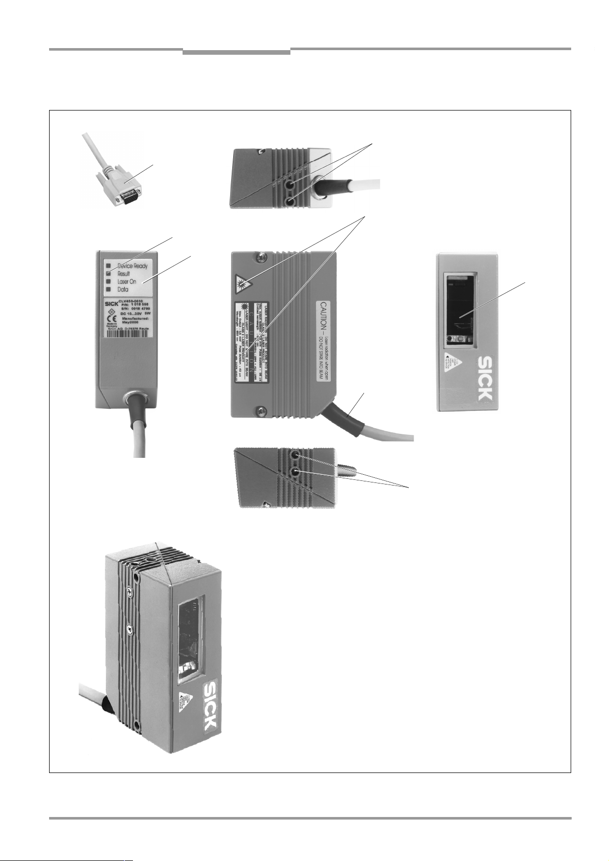
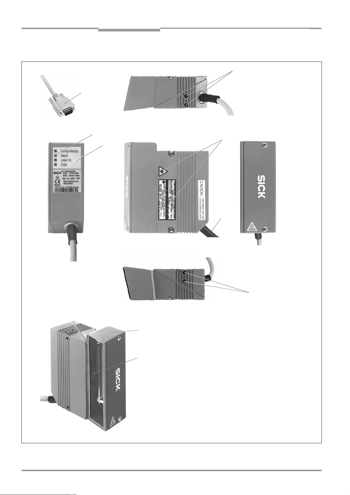
3.1.4 Design line scanner
2
1
4
7
6
3
Front-end reading window
5
2
Legend:
D-Sub HD cable plug, 15-pin
1
Blind hole thread, M 5, 5 mm deep
2
Reading window
3
Laser warning lables
4
Connection cable
5
Sound opening of the beepers (concealed)
6
LEDs (status indicators)
7
Fig. 3-1: Design of the line scanner CLV 45x
8 009 139/K949/06-06-2002© SICK AG · Division Auto Ident · Germany · All rights reserved
3-3
Page 22
Chapter 3 Operating Instructions
Product description
CLV 45x Bar Code Scanner
3.1.5 Design line scanner with oscillating mirror
2
1
6
5
3
4
2
Side-end reading window
7
8
Fig. 3-2: Design of the line scanner with oscillating mirror CLV 45x
©
3-4
SICK AG · Division Auto Ident · Germany · All rights reserved 8 009 139/K949/06-06-2002
Legend:
D-Sub HD cable plug, 15-pin
1
Blind hole thread, M 5, 5 mm deep
2
Laser warning lables
3
Connection cable
4
Sound opening of the beepers (concealed)
5
LEDs (status indicators)
6
Integrated oscillating mirror
7
Reading window
8
Page 23
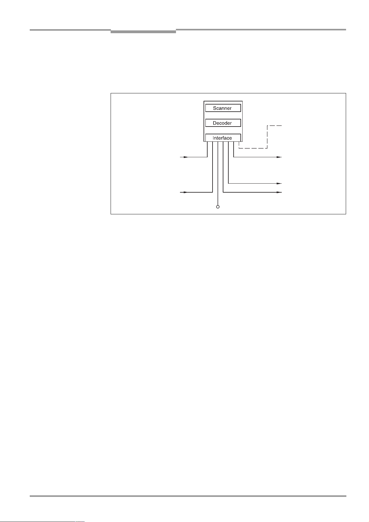
Operating Instructions Chapter 3
Photoelectric switch
Reading pulse
Signal
Focal position changeover
Teach-in match code 1,
etc.
PC
Operation
parameterization, etc.
HOST
Further processing
of the reading result
Status display
e. g. Good Read
e. g. No Read
CLV 45x Bar Code Scanner
Product description
3.2 Working method of the device
The CLV detects bar codes by means of a scan line and decodes them. The CLV transmits
the data via the main data interface (serial host interface) to a host/PC for further processing.
"Terminal"
"Sensor 1"
"Sensor 2"
"Host"
"Result 1"
"Result 2"
8 009 139/K949/06-06-2002© SICK AG · Division Auto Ident · Germany · All rights reserved
Fig. 3-3: Block diagram: Functions of the CLV
The CLV provides two decoders for decoding:
•
The SMART decoder (SICK Modular Advanced Recognition Technology) for decoding
bar codes with a small "aspect ratio" (ratio of the code height to the code length), for
bar codes with damaged or soiled printing image as well as for reading bar codes under
a strong tilt (azimuth angle)
•
The proven standard decoder of the CLV series
The CLV derives useful data for diagnostics from the reading processes, which can also be
transferred to the host. In addition it carries retrievable operating data. The quality of the
reading can be checked in the "Percentage evaluation" operating mode.
The CLV requires suitable triggering in order to start a reading process when there is an
object in the reading area. This results in a time window ("reading interval") for the reading
process being opened in the CLV. In the default setting triggering is carried out by means of
an external reading pulse sensor. Alternative trigger sources are free-running operation or a
command via the host interface.
Four LED status displays inform optically on the current operating state.
A beeper (buzzer) signals the status of the read result acoustically. In the default setting the
Good Read function is selected to this purpose.
In the case of external triggering by a sensor the "Sensor 1" switching input signals the CLV
when it is to start a reading. The "Sensor 2" switching input is used to change over the focal
position. It can be used alternatively e. g. for the teach-in of a match code. The switching
outputs "Result 1" and "Result 2" can have various output functions of the result status assigned to them and control external devices, such as a PLC.
The CLV is operated and configured via the auxiliary data interface (serial terminal interface)
by means of the user interface of the "CLV-Setup" PC software or via the host interface/
terminal interface by means of command strings.
System, warning and error messages provide support in setting up and searching for errors
during starting up and reading operation.
3-5
Page 24
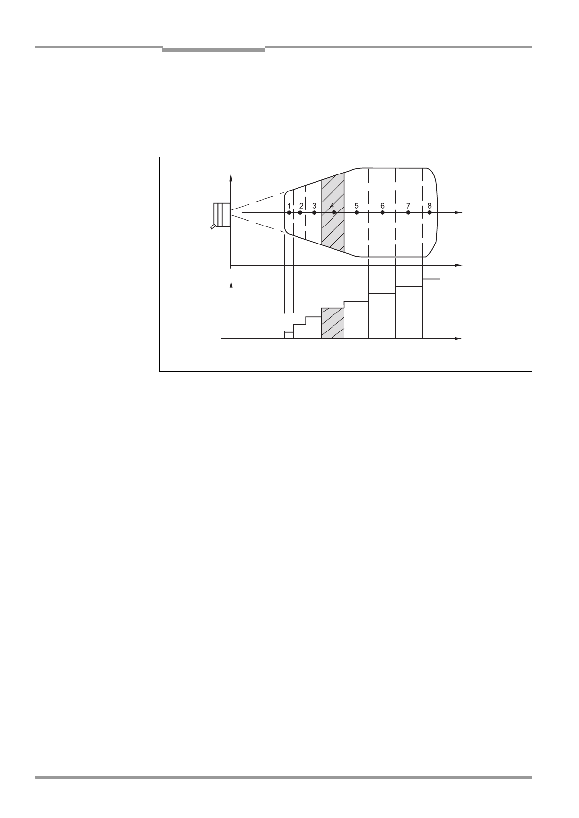
Chapter 3 Operating Instructions
Reading
field
height
Focal
position
Reading
distance
DC 8
DC 7
DC 6
DC 5
DC 4
DC 3
DC2
DC 1
DC = Distance configuration
Focal position
Reading
distance
Product description
CLV 45x Bar Code Scanner
3.2.1 Changeable focal position
The CLV 45x can change its focal position dynamically and thus cover a large reading range.
To this purpose a max. of 8 reading ranges can be defined internally as a distance configuration and can be approached during reading mode by the optics in a random order
Fig. 3-4
(
).
3-6
Fig. 3-4: Focal position changeover: Division of the overall reading range into distance
The changeover is carried out on the basis of the changing object distance (when reading
from above: object height detection). The trigger source for the changeover with a maximum
of 2 st ages is a s ignal at t he "Se nsor 2 " swi tch ing inp ut. For th e cha ngeov er w ith a m axim um
of 8 stages a command at the host interface interface or the integrated timer (e. g. for
search runs). At the line scanner with oscillating mirror additionally the oscillating mirror inversion points of the two-sided displacement. The distance configurations are assigned to
the changeover sequence by means of a programmable assignment table.
3.2.2 Variants of the scanning process
Line scanner
Generates one scan line. The reading area height (for evaluating the usable length of the
scan line) depends on the reading distance because of the V principle of the beam deflection.
Line scanner with oscillating mirror
The oscillating mirror additionally deflects the scan line vertically to the scanning direction to
both sides at a low oscillating frequency. This means that the CLV can also scan larger areas
or ranges for bar codes. The reading field height (for evaluating the usable length of the scan
line) depends on the reading distance because of the V principle of the beam deflection.
In addition to parking (fixed position) and the simple deflection with a maximum deflection
width, optimized function runs of the oscillating mirror are also possible:
•
Oscillation with variable deflection per distance configuration
•
One-Shot: Single defined deflection per reading pulse (forward and return).
©
SICK AG · Division Auto Ident · Germany · All rights reserved 8 009 139/K949/06-06-2002
configurations
Page 25
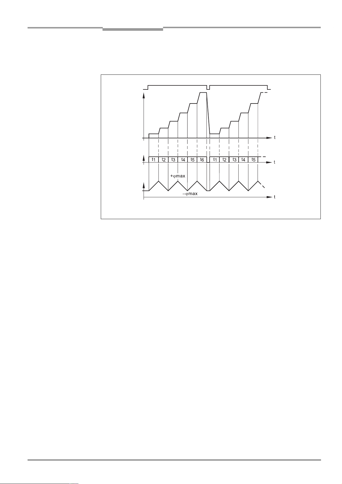
Operating Instructions Chapter 3
Deflection
angle
Oscillating mirror
inversion points
Reading pulse
Focal
position
Timer
or
CLV 45x Bar Code Scanner
Product description
For the case of reading without a transport movement of the object
Fig. 3-5
shows an example of the triggering of the focal position changeover by means of the internal timer or of
the oscillation mirror inversion points ("search run") at 6 distance configurations.
Fig. 3-5: Oscillating mirror: Example of the focal position changeover in the search run
3.3 Display and operating elements
3.3.1 Operating elements
The CLV is operated and configured via the terminal interface by means of the user interface
of the "CLV-Setup" PC software or via the host interface/terminal interface by means of
command strings. Manifold parameterization options allow the adaptation to highly different
applications.
The following can also be set
•
Configuration of the code types to be read
•
Reading, evaluation and output properties
•
Communication parameters of the host interface
•
Structure of the data output string of the host interface for “Good Read“ and “No Read“
•
Function of the terminal interface
Chapter 10.4 Installing and operating the "CLV-Setup" PC software, Page 10-20
the installation of the "CLV-Setup" PC software and the use of the user interface. The configuration (parameterization) is explained in
Page 6-4
.
Chapter 6.4 Configuration (parameterizing),
describes
8 009 139/K949/06-06-2002© SICK AG · Division Auto Ident · Germany · All rights reserved
3.3.2 Function of the LEDs
Four LEDs signal the operating state, the activity of the laser diode, the status of the read
result and the data transfer to the host interface. The LEDs (
tioned on the rear narrow side of the device.
Table 3-2
Fig. 3-6, Page 3-8
) are posi-
lists the meaning of the LEDs in the
various operating modes/functions.
3-7
Page 26
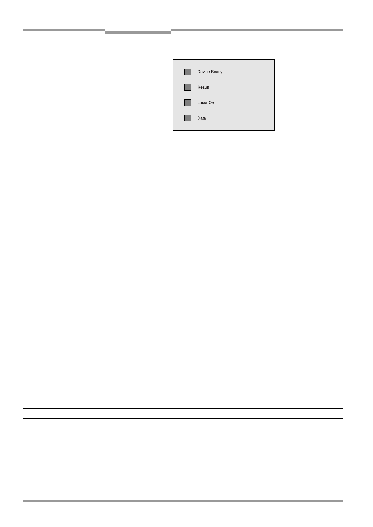
Chapter 3 Operating Instructions
Operating mode LED Display Function
Start Device Ready
Laser On
Reading mode Device Ready
Laser On
Result
Data
Percentage
evaluation
Profileprogramming
Auto Setup Laser On
Adjusting mode Laser On
Show CP limits Laser On
Table 3-2: Meaning of the LEDs
Laser On
Result
Laser On
Product description
Fig. 3-6: LEDs
Orange
Orange
Orange
Orange
Orange LED is coupled to the "Result 2" switching output. It displays the result
Orange
Orange
Orange Behavior depends on the reading quality:
Orange
Orange
Orange
Orange
•
•
•
•
•
•
status selected for the set pulse duration of the output.
•
•
•
•
•
•
•
•
•
•
•
•
CLV 45x Bar Code Scanner
Lights up after activation if the self-test was successful and the waiting
time for reading the Profile bar codes has passed
Lights up while the laser diode for reading the Profile bar codes is active
Lights up constantly
Extinguishes at a change to another operating mode/function
Lights up when the laser diode for reading is active.
(The laser diode is switched on and off by the reading pulsing.)
Lights up constantly in the pulsing type "free-running", since the laser
diode is constantly active.
Lights up after a successful reading (default setting: Good Read)
Lights up when the code comparison is activated, the read bar code
agrees with the specified comparison code(s) and the corresponding
event status output for the "Result 2" output has been selected.
Flickers when the CLV on the host interface transfers data to the host
Lights up constantly since free running operation
Extinguishes if the reading rate < 30 %
Flashes twice per second if the reading rate is 30 % ... 70 %
Flashes five times per second if the reading rate is 70 % ... 90 %
Lights up constantly, if reading rate > 90 %
Lights up while the Profile bar codes are being read, since free running
operation.
Lights up while the application-specific bar codes are being read, since
free running operation.
Lights up constantly since free running operation
Flashes alternatively bright/darker in the rhythm of the partial shielding of
the scan line
3-8
©
SICK AG · Division Auto Ident · Germany · All rights reserved 8 009 139/K949/06-06-2002
Page 27
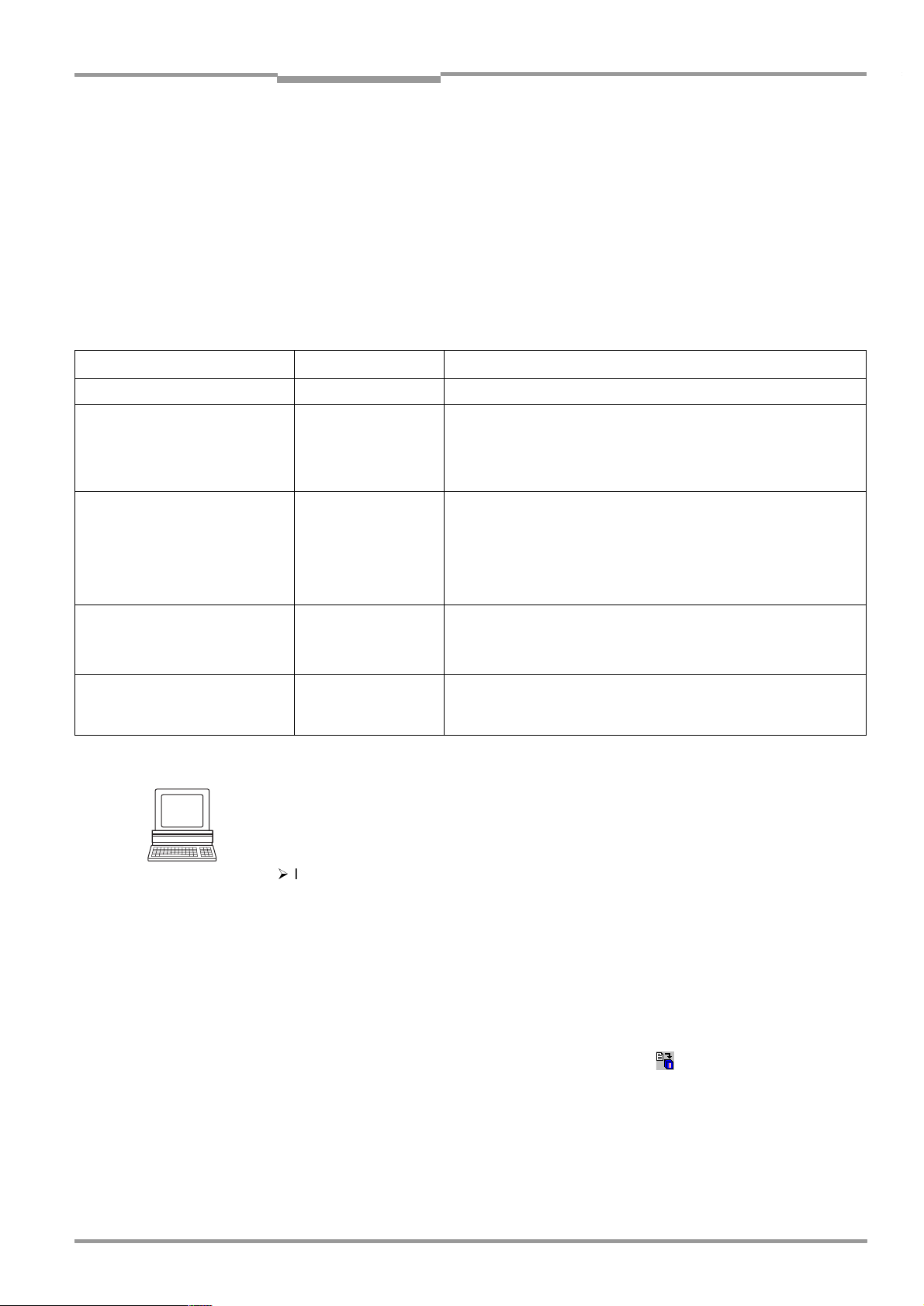
Operating Instructions Chapter 3
CLV 45x Bar Code Scanner
Product description
3.3.3 Function of the beeper (buzzer)
The beeper signals the successful execution of device functions and any malfunctions
by means of differing sequences and lengths of sounds (
troubleshooting please refer to
Chapter 8.5 Troubleshooting, Page 8-6
Table 3-3
). For information on
.
In the default setting the beeper is activated and displays the "Good Read" result status for
reading mode. The further description in these operating instructions assumes that the
beeper is operated in reading mode in the default setting.
The sound opening of the beeper is positioned on the rear narrow device end concealed
under the LED labeling.
Operating mode/function Sequence of sounds Function of the beeper
Start Beep
Reading mode Beep Beep
Beep
Profile programming
Start Auto Setup
Profile programming Beep
Exceeding of the laser timeout Beep Beep Beep
Table 3-3: Function of the beeper
HINT
Beep
Beep Beep
Beep (long sound)
Beep Beep
The behavior of the beeper in reading mode can be modified by means of the D
FIGURATION
tab card of the user interface of CLV-Setup.
•
Signals after activation that the self-test was successful
•
Confirms starting of the reading mode after the activation and after
the waiting time of 5 s for reading the Profile bar codes has passed
•
Confirms a successful reading ("Good Read"; default setting) and
the output of the read result
•
Confirms successful reading of the Profile bar code for starting/
ending the Auto Setup
•
Confirms successful reading of the application-specific bar code
and starting of the reading mode.
•
Signals that the application-specific bar code was not read
•
Confirms successful reading of the Profile bar code
•
Confirms starting of the reading mode 10 s after reading the last
Profile bar code
•
Signals de-activation of the laser diode after the laser timeout of
10 min (default setting) has been exceeded in reading mode.
However, the reading pulse is not terminated.
EVICE CON
-
ON/OFF:
¾
In order to switch off the beeper, click on the B
EEPER ACTIVE
section in order remove the check mark.
Output function for the result status:
1. Click on the E
RESULT OUTPUTS
2. Click on the B
DIT RESULT OUTPUTS
dialog box is displayed.
EEPER
list box in the R
command button in the R
ESULT FUNCTIONS
The list with the selectable functions for the result status is displayed.
3. Click on the desired function and confirm the dialog box with OK.
4. Carry out the download to the CLV. To do so, click on in the toolbar.
OWNLOAD PARAMETERS
The D
5. Confirm the dialog box with the saving option P
dialog box is opened.
ERMANENT
The CLV operates the beeper with the selected values for the function of the result status
display.
8 009 139/K949/06-06-2002© SICK AG · Division Auto Ident · Germany · All rights reserved
check box in the R
ESULT OUTPUT
section.
.
ESULT OUTPUT
section. The E
DIT
3-9
Page 28

Chapter 3 Operating Instructions
Product description
CLV 45x Bar Code Scanner
Notes
3-10
©
SICK AG · Division Auto Ident · Germany · All rights reserved 8 009 139/K949/06-06-2002
Page 29

Operating Instructions Chapter 4
CLV 45x Bar Code Scanner
Installation
4
Installation
4.1 Overview of the installation steps
•
Replacing the language version of the laser warning label (if required)
•
Selecting the installation site for the CLV
•
Aligning the CLV to the bar code
•
Installing the CLV
•
Installing the AMV/S 40 connection module
•
Connecting the CLV to the AMV/S 40 connection module
•
Adjusting the CLV
•
Installing the reading-pulse sensor for reading pulse triggering
•
Optional for focal point changeover:
Mounting the sensor for detecting the object distance
4.2 Preparations for installation
4.2.1 Laying out the components to be installed ready
•
CLV bar code scanner
4.2.2 Laying out the accessories ready
•
Mounting bracket No. 2 020 410 with two screws M 5 x 8 mm and 2 washers (not
included in the CLV scope of delivery ) or
Mounting bracket No. 2 022 564 with 3 screws M 5 x 8 mm, 3 spring washers and 2
hexagon screws M 5 x 12 mm with washers (not included in the scope of delivery) or
Rod clamp No. 2 023 691 with 3 screws M 5 x 8 mm and 3 spring washers (not included in the scope of delivery)
Alternatively, if the user provides a retainer:
Stable mounting device which allows the alignment of the CLV to be changed in the
X- and Y-axes. In the line scanner version the weight of the CLV amounts to 530 g, while
the line scanner with oscillating mirror weighs 700 g, each with a connection cable.
Two screws M 5 for the CLV. The screw length depends on the wall thickness of the
retainer used. Max. screw-in depth into CLV 5 mm from housing surface.
•
AMV/S 40 connection module, optionally additionally with CL 20 mA interface converter (not included in the CLV scope of delivery)
•
Reading-pulse sensor for external reading-pulse triggering, e. g. photoelectric reflex
switch/photoelectric proximity switch (not included in the CLV scope of delivery)
•
Optional for focal point changeover: Sensor for detecting the reading distance, e. g.
photoelectric reflex switch/photoelectric proximity switch (not included in the CLV
scope of delivery)
4.2.3 Laying out the required tools ready
•
Two/three screws M 5 for fastening the SICK mounting bracket to the mounting base.
Screw length depends on the wall thickness of the base.
•
Set of laser warning labels (if required)
8 009 139/K949/06-06-2002© SICK AG · Division Auto Ident · Germany · All rights reserved
4-1
Page 30
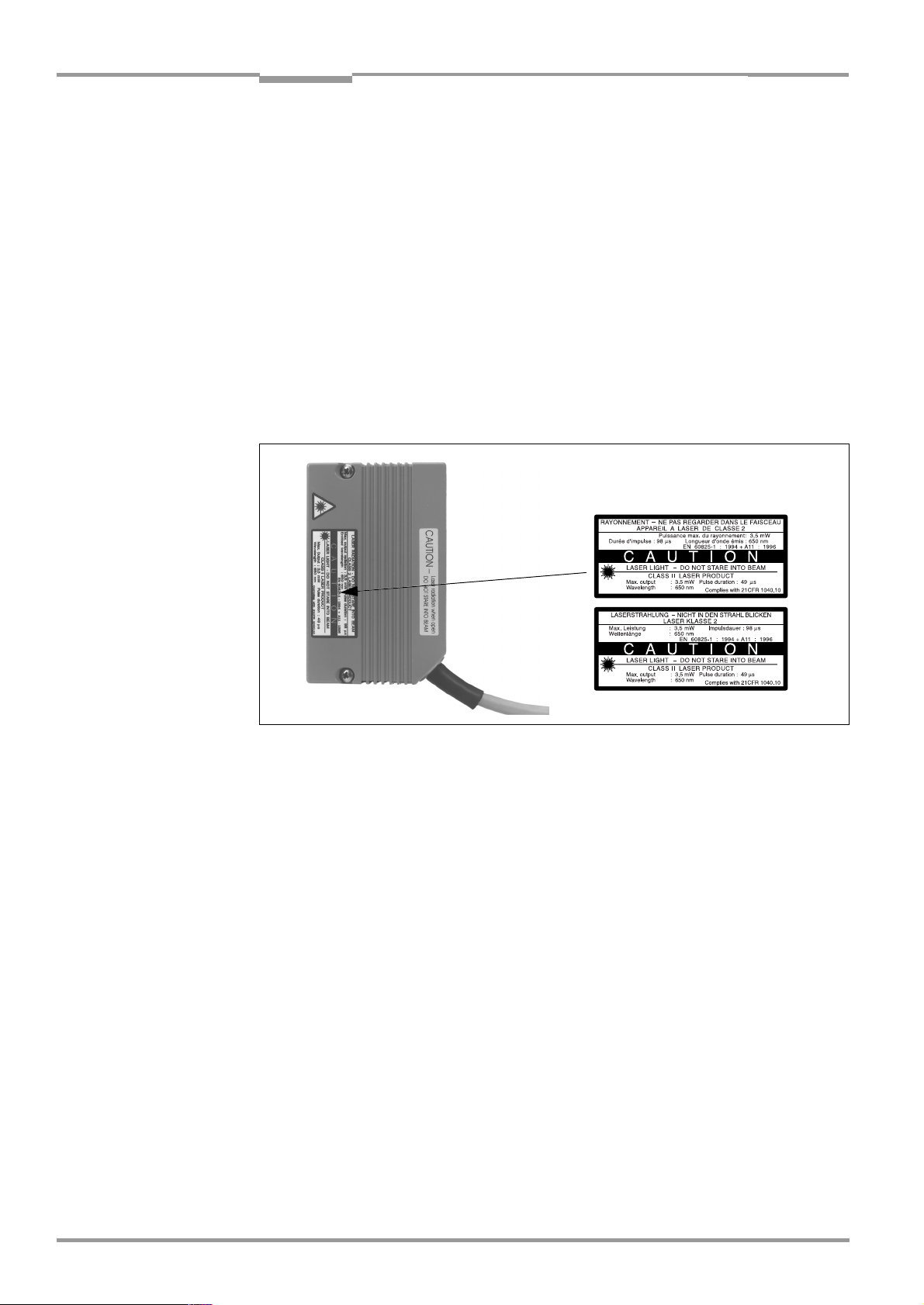
Chapter 4 Operating Instructions
Installation
CLV 45x Bar Code Scanner
•
Labels with terminal designations of the CLV 43x/44x for the AMV/S 40 connection
module (also valid for CLV 45x)
•
Tool
•
Measuring tape (up to 2 000 mm)
•
Angulometer
4.2.4 Replacing the laser warning label
If required, stick the warning label in the required language variant over the British/US
warning applied to the CLV (
Fig. 4-1
).
The enclosed set of laser warning labels consists of:
•
A German/US English laser warning label
•
A French/US English laser warning label
Also refer to
Chapter 2.3 General safety instructions and protective measures, Page 2-1
Enclosed set of labels:
.
Fig. 4-1: Example of line scanner: Exchanging the laser warning label
4.2.5 Selecting the installation site
When selecting the installation site take the distance between the CLV and the host as well
as the distance between the CLV and the bar code into consideration.
Distance between the CLV and the host
The CLV can be mounted at a max. of 1 200 m from the host without being connected to a
SICK network or to a bus connection. However, the possible distance depends on the
selected physical implementation of the host interface and the set data transfer rate (refer
Table 5-2, Page 5-2
to
).
Distance between the CLV and the AMV/S 40 connection module
The AMV/S 40 connection module should not be installed more than 10 m from the CLV,
since the PC with the "CLV-Setup" software accesses the terminal interface of the CLV via
the module (RS-232 type).
4-2
©
SICK AG · Division Auto Ident · Germany · All rights reserved 8 009 139/K949/06-06-2002
Page 31

Operating Instructions Chapter 4
10
14.4
4
35.9
13.2
10
4
35.9
Lower side Upper side
Blind hole thread,
M 5, 5 mm deep
CLV 45x Bar Code Scanner
Installation
4.2.6 Mounting accessories
The CLV is fastened by means of two blind hole threads (M 5), which are positioned on the
narrow upper and lower device sides.
Fig. 4-2
shows the position of the thread at the line
scanner.
The complete housing dimensions of the CLV are shown in
Page 9-4
.
Fig. 9-1, Page 9-3
and
Fig. 9-2,
Fig. 4-2: Example of line scanner: Position of the fastening thread at the CLV
The CLV can be installed by means of the following SICK retainers:
•
Mounting bracket No. 2 020 410
•
Mounting bracket No. 2 022 564
•
Rod clamp No. 2 023 691
The design of the brackets supports a number of mounting variants and the alignment of
the CLV in two levels.
Fig. 4-3
and
Fig. 4-4
show two mounting examples.
The elongated holes of the mounting bracket No. 2 020 410 make it possible to align the
CLV finely by an angle of rotation of ±15°. The elongated holes of the mounting bracket
No. 2 022 564 and the rod clamp N0. 2 023 691 make it possible to rotate the CLV freely.
Fig. 4-3: Line scanner: Example of the mounting possibilities of the CLV with the mounting
bracket No. 2 020 410
8 009 139/K949/06-06-2002© SICK AG · Division Auto Ident · Germany · All rights reserved
4-3
Page 32

Chapter 4 Operating Instructions
Line scanner Line scanner with
oscillating mirror
Installation
CLV 45x Bar Code Scanner
Fig. 4-4: Line scanner: Example of the mounting possibilities of the CLV with the mounting
bracket No.
2 022 564
The dimensioning of the mounting brackets is shown in
wings of the accessories, Page 10-54
.
Chapter 10.12 Dimensioned dra-
Hint For applications with strong mechanical vibrations applied to the CLV the mounting bracket
with vibration damper No. 2 031 342 is available. See also
cessories, Page 10-51
.
Chapter 10.11.1 Mounting ac-
4.2.7 Distance between the CLV and the bar code
Theoretical positioning of the scan line to the bar code
Either a line scanner or a line scanner with oscillating mirror is used as the CLV, depending
on the respective application.
Fig. 4-5
shows the theoretical positioning of the two scanning
processes to the bar code on the object.
Fig. 4-5: Positioning of the scanning process to the bar code and to the conveyor direction
Reading distance to the bar code and the aperture angle
The distance between the reading window of the CLV and the bar code may not exceed the
limits imposed by the device.
(front-end reading window), Page 10-5
scanner with oscillating mirror (side-end reading window), Page 10-9
the reading field as a ratio of the reading distance for various resolutions (module widths).
Fig. 4-7
aperture angle α of both scanning processes.
4-4
©
shows the definition of the reading distance a from the reading window and of the
SICK AG · Division Auto Ident · Germany · All rights reserved 8 009 139/K949/06-06-2002
α
Chapter 10.2.4 Depths of field for CLV 450 line scanner
Chapter 10.2.5 Depths of field for CLV 450 line
to
shows the height of
Page 33

Operating Instructions Chapter 4
a
a
Line scanner Line scanner with
oscillating mirror
Reading distance
Reading di-
a
a
Reading distance aReading distance a
CLV 45x Bar Code Scanner
Installation
Fig. 4-6: Definition of the reading distance a and of the aperture angle
The effective aperture angle α amounts for the CLV 450 to a max. of 50°, for the CLV 451
to a max. of 55° at both scanning processes. Due to the V principle of the beam deflection
the reading field height (for evaluating the usable length of the scan line) depends on the
reading distance.
Angle position of the CLV
The optimum position of the CLV is reached when the scan line passes over the bar code
right-angled (90°) (
Fig. 4-5
and the bar code have to be taken into consideration (
b
α
). Possible reading angles which can occur between the scan line
Fig. 4-7
α:
Azimuth angle (tilt)
β:
a
Reading
range
Angle of inclination (pitch)
γ:
Angle of rotation (skew)
and
Table 4-1
).
g
Reading
distance
Fig. 4-7: Line scanner: Reading angle occurring between the scan line and the bar code
8 009 139/K949/06-06-2002© SICK AG · Division Auto Ident · Germany · All rights reserved
Angle Limit
Azimuth α (tilt) Max. ± 45° (in scan axis and at focal position 200 ... 900 mm for a modul
Inclination β (pitch) Max. ± 45° (depending on module width and focal position)
Rotation γ (skew) Max. ± 45° (depending on module width and focal position)
Table 4-1: Permitted reading angle between the scan line and the bar code
width of 0.35 ... 1.0 mm)
4-5
Page 34

Chapter 4 Operating Instructions
Line scanner
(front-end reading window)
Line scanner with oscillating mirror
(side-end reading window)
(top view) (side view)
Installation
CLV 45x Bar Code Scanner
Avoiding surface reflections
If the light of the scan line falls exactly vertically on the surface of the bar code, disturbing
reflections can occur when the reflected light is received. In order to avoid this effect the
CLV must be installed so that the emitted light is tilted relative to the perpendicular.
Fig. 4-8: Avoiding surface reflections: Angle between the emitted light and the bar code (tilted
away from the perpendicular)
At the line scanner with oscillating mirror the laser beam is emitted during oscillating mode
at an angle of 105° to the housing during the pass through the neutral position CW = 50).
The device can only be mounted flush to the edge at the transport unit if the deflection ranges of the oscillating mirror is small. Otherwise the device also has to be mounted at an angle of inclination of 15 in order to attain symmetrical deflection ranges.
4.2.8 Counting direction of the code position CP and of the code angle CW
Explanation The CLV can scan and decode several bar codes during every reading.
In the process it determines the local reading diagnostic data for each bar code:
•
The position (CP value) of the bar code center within the scan line
•
In addition in case of a scanning process with oscillating mirror the deflection angle of
the scan line (CW value) under which the bar code center is detected
Fig. 4-9
shows the counting direction of the code position and of the code angle.
The determination of the two data allow identical bar codes (code type, code length and
data contents) to be separated as well as the local assignment of the bar code data in the
read result to its position on the object.
©
4-6
SICK AG · Division Auto Ident · Germany · All rights reserved 8 009 139/K949/06-06-2002
Page 35

Operating Instructions Chapter 4
CLV 45x Bar Code Scanner
Line scanner Line scanner with oscillating mirror
Installation
100
CP
0
Front-end reading window Side-end reading window
Aperture angle α (opening angle) in the scanning direction: 1° = 2 CP (50° = 100 CP)
Deflection angle of the scan line crosswise to the scanning direction: 1° = 2 CW (20° = 40 CW)
Fig. 4-9: Counting direction of the code position CP within the scan line and of the code angle CW at an oscillating mirror
Hint
In the default setting the CLV does not output the values CP and CW (CW only in case of line
100
CP
0
scanner with oscillating mirror) in the reading result of the host interface. If this is desired for
the evaluation in the host, the output in the separator of the output string can be activated
via the user interface of CLV-Setup.
Configuring the separator:
1. Select the D
2. Click in the S
The E
ATA STRING
EPARATOR
DIT PARAMETERS
tab card.
input field.
: TFS dialog box opens.
3. Click on the parameter CP and/or CW in the desired sequence in the list field.
CP or CW is inserted in the top in the text line.
4. Confirm the dialog box with “OK“.
5. Carry out the download to the CLV. To do so, click on in the toolbar.
OWNLOAD PARAMETERS
The D
6. Confirm the dialog box with the saving option P
dialog box is opened.
ERMANENT
.
The CLV outputs the CP value and the CW value for every bar code in the read result of
the host interface. The values are displayed as 3-digit numbers each in the corresponding separator.
8 009 139/K949/06-06-2002© SICK AG · Division Auto Ident · Germany · All rights reserved
4-7
Page 36

Chapter 4 Operating Instructions
Installation
CLV 45x Bar Code Scanner
4.3 Installation and adjustment of the device
4.3.1 Installing the CLV
1. Prepare the base for mounting the CLV retainer as described in
out the accessories ready, Page 4-1
2. Place the object with the bar code at the planned position at which the reading is to be
carried out within the visual range of the CLV (no transport movement).
3. Depending on the scanning process align the CLV by eye to the bar code so that
−
The narrow device rear with the LED display lies approximately parallel to the bar
code surface at the line scanner
−
The wide side wall with the laser warning labels lies approximately parallel to the bar
code surface at the line scanner with oscillating mirror
Take the reading angles possibly occurring during later readings into account (refer to
Fig. 4-7, Page 4-5
4. If relevant for the evaluation, take the counting direction of the code position and the
code angle into consideration (refer to
5. Mount the CLV retainer on the base.
Danger of damage to the housing!
The maximum screw-in depth of the two blind hole threads M 5 amounts to 5 mm.
Longer screws damage the housing.
¾
Use screws with a suitable length.
).
.
Fig. 4-9, Page 4-7
Chapter 4.2.2 Laying
).
6. Screw the screw M 5 through the retainer into the blind hole thread of the CLV.
7. Tighten the screws slightly.
8. Adjust the CLV as described in
4.3.2 Adjusting the CLV
The "Percentage evaluation" operating mode supports adjustment of the CLV. In this operating mode the CLV displays the quality of the readings of bar codes which are placed
statically into the reading area of the CLV (no transport movement of the object). The CLV
carries out 100 scans each free running and evaluates the reading quality statically. It outputs the read results continuously every 2 s via the terminal interface.
The display behavior of the "Result" LED provides additional optical information on the reading quality:
•
If the LED does not light up, the CLV cannot read the bar code (reading quality < 30 %).
•
If the LED flashes, the CLV can only read the bar code badly
(reading quality 30 % ... 90 %).
•
If the LED lights up continuously, the CLV is aligned optimally (reading quality > 90 %).
In the default setting the scanning frequency amounts to 600 Hz.
1. Connect the CLV to the AMV/S 40 connection module and switch on the supply voltage
of the module (refer to
After the start the CLV confirms the successful self-test with a beeper sound and shortly
afterwards starting of the reading mode is signaled by two consecutive sounds.
The "Device Ready" LED lights up.
Chapter 5.5.3 Connecting the supply voltage, Page 5-4
Chapter 4.3.2 Adjusting the CLV, Page 4-8
.
).
4-8
©
SICK AG · Division Auto Ident · Germany · All rights reserved 8 009 139/K949/06-06-2002
Page 37

Operating Instructions Chapter 4
CLV 45x Bar Code Scanner
Installation
2. Connect the PC to the terminal interface of the CLV. To do so connect the RS-232 data
connection cable to the 9-pin "Service" connector of the module (refer to
Connecting the CAN interface, Page 5-6
).
3. Start Windows and the "CLV-Setup" software on the PC (refer to
ting "CLV-Setup", Page 10-22
).
Chapter 5.5.5
Chapter 10.4.3 Star-
Select the standard decoder:
4. Select the C
5. Click on the S
ODE CONFIGURATION
TANDARD
radio button in the D
tab card.
ECODER
section.
6. Carry out the download to the CLV. To do so, click on in the toolbar.
OWNLOAD PARAMETERS
The D
7. Confirm the dialog box with the saving option T
dialog box is opened.
EMPORARY
.
The CLV operates with the standard decoder.
Activating the percentage evaluation:
8. Select the P
ERCENTAGE EVALUATION
operating mode under V
IEW
in the menu bar.
The dialog box for prompting the distance configuration is opened.
9. Click on the distance configuration which corresponds to the reading distance of the
object. (Default setting: No. 1, focal position F = 900 mm for CLV 450).
10. Confirm the dialog box with "OK".
The terminal emulator is opened and displays the reading result continuously (refer to
Chapter 6.5.2 Percentage evaluation, Page 6-21
).
During all the further steps observe the behavior of the reading quality (as a %)!
Line scanner with oscillating mirror:
In the percentage evaluation mode the CLV behaves in the following manner:
– in “Oscillating“ mode (default setting: oscillating with a fixed amplitude), the CLV shuts
off oscillation and positions the scan line under the angle CW = 50 (corresponding to
an angle of deflection of 105°). This position cannot be altered.
– in “One-Shot“ mode, the CLV also positions the scan line under the angle CW = 50.
– in “Set Position“ mode, the scan line’s selected position remains unchanged.
Carrying out fine adjustment:
11. Align the CLV so that the angle between the scan line and the bar code bars amounts
to approximately 90°.
12. In order to avoid disturbing reflections, turn the CLV out of the perpendicular so that the
emitted light impacts on the bar code at an angle of approx. 105° (line scanner)
Fig. 4-8, Page 4-6
(
).
13. If necessary, position the center of the scan line exactly on the bar code (
Auxiliary functions for adjusting, Page 4-10
).
14. Manually guide objects with bar codes successively under realistic conditions into the
reading area of the CLV and check the read result. If the objects move loosely, check
several different positions (angles) of the bar code and ensure that the limits of the
permitted reading angle is not exceeded.
15. Adjust the CLV so the "Good Read" rate lies between 70 ... 100 %.
In case of different object sizes per defined reading range (distance configuration)
check the selected focal position and if necessary correct the parameterization (refer
Chapter 6.4.3 Guide to parameterization, Page 6-8
to
8 009 139/K949/06-06-2002© SICK AG · Division Auto Ident · Germany · All rights reserved
Chapter 4.3.3
).
4-9
Page 38

Chapter 4 Operating Instructions
"Adjusting mode"
Range masked out
Scan line
Installation
CLV 45x Bar Code Scanner
16. Tighten the screws at the CLV.
The CLV is aligned to the bar code.
4.3.3 Auxiliary functions for adjusting
Adjusting mode
The "Adjusting mode" operating mode supports the optimum positioning of the center of
the scan line on the object. To the purpose the CLV hides half of the scan line from the center (code position CP = 50 to CP = 100). This is carried out irrespective of a selected distance configuration.
Fig. 4-10
shows the resulting appearance of the scan line at the line
scanner.
CP = 100
CP = 50
CP = 0
Fig. 4-10: Line scanner: Appearance of the scan line in the "Adjusting mode" operating mode
Line scanner with oscillating mirror:
In the adjusting mode the CLV behaves in the manner as decribed in the “percentage evaluation mode“ (see
1. Activate the operating mode in accordance with
Page 6-23
Chapter Activating the percentage evaluation:, Page 4-9
Chapter 6.5.3 Adjusting mode,
.
).
2. Position the CLV so that the center of the scan line, symbolized by the end of the scan
line (code position CP = 50), lies in the center of the bar code – in the case of several
bar codes in the center of the field of all the codes.
Show CP Limits
The “Show CP Limits“ operating mode allows you to test whether the desired effect was produced by narrowing the scan line’s active evaluation range via parameterization. The CLV
alternatively hides certains parts of the scan line in accordance with the selected min. and
max. values of the code position.
4-10
For activation of this operating mode and for checking, see
Chapter 6.5.4 Show CP limits,
Page 6-23
©
SICK AG · Division Auto Ident · Germany · All rights reserved 8 009 139/K949/06-06-2002
Page 39

Operating Instructions Chapter 4
Enclosed
bonding label,
large
for CLV 43./44.
CLV 45x Bar Code Scanner
Installation
4.4 Installing the external components
4.4.1 Installing the AMV/S 40 connection module
Terminal assignment
The terminal assignment printed on the board in the connection area of the AMV/S 40 is
valid for the device types CLV 21x/22x/41x. If a CLV 45x is connected via the 15-pin
socket, the resulting terminal assignment deviates from the printed terminal assignment.
This also applies for the representation in the wiring diagram in the housing cover.
Danger of damage to the CLV and external I/O devices!
The deviating display of the terminal strip assignment means that external devices (e. g. PC)
can be connected incorrectly to the CLV and possibly damaged.
¾
Before carrying out the installation stick the two enclosed labels for the CLV 43x/44x
(also valid for CLV 45x) over the printed assignments in the connection area as well as
the wiring diagram in the housing cover.
1. Apply the larger label in the connection area before the terminal strips so that the Terminals 2 and the Terminals 18 agree.
Fig. 4-11
shows the position of the label. Paste
the smaller label correspondingly in the housing cover.
2 3 4 5 6 7 8 9 10 11 12 13 14 15 16 17 18
TxD
RxD
Fig. 4-11: Correction of the printed terminal assignment in the connection area of the AMV/S 40
R+
GN D
Sensor 2
T+
R-/ RxD
T-/ TxD
CAN_L
CAN_H
Result 1
Result 2
SENSOR
Sens GND
GND
GND
+24 V
2. Mount the AMV/S 40 connection module near the CLV. The maximum distance
between the AMV/S 40 and the CLV should not exceed 10 m.
3. Mount the AMV/S 40 so that the access to the opened device is possible at all times.
The terminal interface of the CLV is accessed via the internal "Service" plug.
For detailed information on the installation and electrical installation refer to the
instructions "AMV/S 40 connection module"
8 009 139/K949/06-06-2002© SICK AG · Division Auto Ident · Germany · All rights reserved
(Order No. 8 008 292, English edition).
operating
4-11
Page 40

Chapter 4 Operating Instructions
Installation
CLV 45x Bar Code Scanner
4.4.2 Installing an external reading-pulse sensor
If the CLV is triggered by means of an external reading-pulse sensor, the sensor is installed
near the CLV. In the default setting the "Sensor 1" switching input is selected as the trigger
source for this triggering type.
Fig. 4-12
shows two examples of the installation site of a photoelectric reflex switch. This
depends on the distance a of the bar codes to the front object edge. Depending on the application the sensor is to be installed so that bar codes on objects of different sizes can be
read completely during the time window of the evaluation (reading interval).
Bar code in the center or at the end of the object
to be conveyed
a
b
b < a !
Fig. 4-12: Line scanner: Installation example for positioning the external reading-pulse sensor
Bar code at the beginning of the object
to be conveyed
a
b
1. Install the reading-pulse sensor at the installation site.
2. Connect the reading-pulse sensor via the AMV/S 40 connection module to the
"Sensor 1" switching input of the CLV (refer to
switching input, Page 5-7
).
Chapter 5.5.7 Wiring the "Sensor 1"
3. Connect the CLV to the AMV/S 40 connection module and switch on the supply voltage
of the module (refer to
Chapter 5.5.3 Connecting the supply voltage, Page 5-4
After the start the CLV confirms the successful self-test with a beeper sound and shortly
afterwards starting of the reading mode is signaled by two consecutive sounds. The
"Device Ready" LED lights up.
4. Connect the PC to the terminal interface of the CLV. To do so connect the RS-232 data
connection cable to the 9-pin "Service" connector of the module (refer to
Connecting the CAN interface, Page 5-6
).
5. Start Windows and the "CLV-Setup" software on the PC (refer to
ting "CLV-Setup", Page 10-22
6. Select the R
EADING MODE
).
menu item under V
IEW
in the menu bar.
The terminal emulator window opens. The CLV is in reading mode.
During all the further steps observe the behavior of the reading result!
Line scanner with oscillating mirror:
In reading mode the CLV deflects the scan line in the default setting with a frequency of
1 Hz around the position CW = 50 at a maximum angle of ±20°.
50 CW corresponds to a light emission under 105°.
7. Manually guide objects with bar codes successively under realistic conditions into the
reading area of the CLV.
8. Check that the cycle is triggered and the read result.
9. Repeat the procedure during transport mode.
10. Check whether the reading process is synchronized with arriving objects.
b < a !
).
Chapter 5.5.5
Chapter 10.4.3 Star-
4-12
©
SICK AG · Division Auto Ident · Germany · All rights reserved 8 009 139/K949/06-06-2002
Page 41

Operating Instructions Chapter 4
Reading
distance
DC 1
DC 2
DC = Distance configuration
h 2
h 1
Object distance
CLV 45x Bar Code Scanner
Installation
Parameterizing an external sensor as the trigger source (not at the default setting):
1. Select the D
2. Click on the E
DIT READING TRIGGER
The E
3. Select the S
EVICE CONFIGURATION
DIT READING TRIGGER
ENSOR INPUT (ACTIVE HIGH
tab card.
command button.
dialog box is opened.
) radio button and confirm the dialog box.
4. Carry out the download to the CLV. To do so, click on in the toolbar.
OWNLOAD PARAMETERS
The D
5. Confirm the dialog box with the saving option P
dialog box is opened.
ERMANENT
.
The CLV operates with the "Sensor 1" switching input as the external trigger source.
Current in the input starts the reading pulse.
4.4.3 Mounting the sensor for detecting the object distance
The CLV provides a dynamic focal position changeover for serial covering of a large reading
range. To this purpose a changeover with a maximum of 2 stages can be implemented via
the "Sensor 2" switching input.
Fig. 4-13
shows an example for reading from above. A
photoelectric reflex switch is, for example, used for the detection of the object distance. This
application is suitable for such object sizes whose difference can be covered by 2 changeover ranges. The distance sensor is to be positioned so that these object sizes are
classified clearly and two overlapping reading ranges arise which can be formed with the
depths of field of the CLV. The two distance configurations (reading ranges) are assigned
from a maximum of 8 configurations by means of the internal assignment table (combinatorics). In the default setting the "Sensor 2" switching input is selected for the focal position
changeover.
Fig. 4-13: CLV 44x: Installation example for positioning the object distance detection
1. Read the depths of field of the CLV for the specified resolution of the bar code manually
from the diagrams in
end reading window), Page 10-5
Chapter 10.2.4 Depths of field for CLV 450 line scanner (front-
Chapter 10.2.5 Depths of field for CLV 450 line
or
scanner with oscillating mirror (side-end reading window), Page 10-9
note suitable focal positions for overlapping reading ranges.
– or –
Have the depth of field determined automatically by means of the CLV Assistant in the
8 009 139/K949/06-06-2002© SICK AG · Division Auto Ident · Germany · All rights reserved
CLV-Setup user interface (values are read automatically into the tab cards).
. Search for and
4-13
Page 42

Chapter 4 Operating Instructions
Installation
CLV 45x Bar Code Scanner
2. Install the distance sensor (photoelectric reflex switch) for the object height detection
so that the optical path for the reading range 1 remains uncovered (also refer to
Table 5-8, Page 5-9
). It is advisable to install the distance sensor against the direction
of travel of the conveyor unit approx. 100 mm before the reading-pulse sensor.
3. Connect the distance sensor via the AMV/S 40 connection module to the "Sensor 2"
switching input of the CLV (refer to
Page 5-8
).
Chapter 5.5.8 Wiring the "Sensor 2" switching input,
4. After you have manually determined the focal positions for the two required reading
ranges use the R
EADING CONFIGURATION
To do so click on the D
ISTANCE CONFIGURATION/ASSIGNMENT TABLE
tab card of the CLV-Setup user interface.
command button and
edit the dialog box correspondingly.
5. Select the standard decoder as described in
Chapter 4.3.2 Adjusting the CLV, Page 4-8
and call up the percentage evaluation temporarily.
6. Check the reading quality for the two distance configurations in static operation.
(no transport movement of the objects).
7. Finally check the function of the distance detection realistically in reading mode.
To this purpose observe the read result in the terminal emulator as described in
Chapter 4.4.2 Installing an external reading-pulse sensor, Page 4-12
.
Default setting of CLV 450: F1 = 900 mm, F2 = 500 mm, F3 = 200 mm
Note The integrated timer or the oscillating mirror inversion points can be used to change over
the CLV for slow search runs between a maximum of 8 distance ranges.
Command strings can be used to change the CLV synchronously to the process over
between 8 distance ranges.
4.5 Disassembling the device
1. Switch off the supply voltage of the AMV/S 40 connection module.
2. Pull the cable plug of the CLV off after loosening the fixing screws from the AMV/S 40
connection module.
3. Unscrew the CLV from the mounting device.
In order to dispose of the unit after final removal from service without damaging the
environment proceed as described in
Chapter 7.3 Disposal, Page 7-2
.
4-14
©
SICK AG · Division Auto Ident · Germany · All rights reserved 8 009 139/K949/06-06-2002
Page 43

Operating Instructions Chapter 5
CLV 45x Bar Code Scanner
Electrical installation
5
Electrical installation
5.1 Overview of the installation step
•
Connect the CLV to the SICK AMV/S 40 connection module
•
Adapt the interconnection of the host interface in the module to the host interface of
the CLV
•
Wire the data and function interfaces of the CLV in the connection module
•
Connect the PC to the connection module (at the terminal interface of the CLV)
•
Connect the connection module to the supply voltage
5.2 Electrical connections and cables
The electrical connection of the CLV consists of a 15-pin D-Sub HD cable plug. The following
interfaces are implemented via it:
•
Three serial data interfaces (host interface, CAN interface and terminal interface)
•
Two switching inputs (external reading-pulse as well as multifunctional input)
•
Two switching outputs (output of result status functions, for connection e. g. to a PLC)
•
Power supply
¾
Wire all the connections with copper wires with a minimum wire cross-section of
0.09 mm
2
!
Photoelectric
switch
Reading pulse
Photoelectric
switch
Focal position
changeover
Trigger One-Shot
Conveyor increment
Teach-in match code 1
– – Cable if required
5.2.1 Connections/Cables when the AMV/S 40 connection module is used
The AMV/S 40 connection module is suitable for industrial-type connection of the CLV to
the I/O devices (distributor function) and the power supply. The direct connection to the
host (point-to-point), the inclusion into the SICK network or into a daisy-chain set-up (passthrough or master/slave configuration) can be realized with it.
Fig. 5-1
shows the connecting principle of the AMV/S 40 for a CLV.
CLV 45x
AMV/AMS 40
connection module
HOST/PLC
PLC
10 ... 30 V DC (AMV 40-011)
230 V AC (AMS 40-013)
115 V AC (AMS 40-012)
Fig. 5-1: Block diagram: Connection of the CLV to the AMV/S 40 connection module
8 009 139/K949/06-06-2002© SICK AG · Division Auto Ident · Germany · All rights reserved
5-1
Page 44

Chapter 5 Operating Instructions
Electrical installation
CLV 45x Bar Code Scanner
1. Observe the modified terminal assignment for the CLV in the connection area of the
AMV/S 40 (refer to
Page 4-11
).
Chapter 4.4.1 Installing the AMV/S 40 connection module,
2. The wiring and configuration of the AMV/S 40 connection module is described in the
Operating instructions "AMV/S 40 connection module ”
(Order No. 8 008 292, English
edition).
5.3 Pin assignment of the connecting plug
5 6
1
11
Pin Signal Function
1 +10 ... +30 V DC Supply voltage
2 RxD (terminal) Terminal interface (receiver)
3 TxD (terminal) Terminal interface (sender)
4 Sensor 2 Switching input, selectable function
5 GND Ground (chassis ground)
6 RD+ (RS-422/485) Host interface (receiver)
7 RD- (RS-422/485); RxD (RS-232) Host interface (receiver)
8 TD+ (RS-422/485) Host interface (sender)
9 TD- (RS-422/485); TxD (RS-232) Host interface (sender)
10 CAN H CAN bus (IN/OUT)
11 CAN L CAN bus (IN/OUT)
12 Result 1 Switching output, selectable function
13 Result 2 Switching output, selectable function
14 Sensor 1 Switching input for external reading pulse
15 SensGND Common ground for all inputs
– – Shield
10
15
5-2
Table 5-1: Pin assignment of the 15-pin D-Sub HD cable plug
5.4 Preparation of the electrical installation
5.4.1 Requirements for the host interface
The host interface of the CLV can be operated as an RS-422/485 unit or as an RS-232 unit.
Table 5-2
mission rate.
Interface type Transmission rate Distance to the host
RS-232 Up to 19 200 bits/s Max. 10 m
RS-422/485
1) If the cable is terminated correspondingly
Table 5-2: Maximum cables lengths between the CLV and the host
©
SICK AG · Division Auto Ident · Germany · All rights reserved 8 009 139/K949/06-06-2002
shows the recommended maximum cable lengths as a function of the data trans-
38 400 ... 57 600 bits/s Max. 3 m
1)
Max. 38 400 bits/s Max. 1 200 m
Max. 57 600 bits/s Max. 500 m
Page 45

Operating Instructions Chapter 5
CLV 45x Bar Code Scanner
Electrical installation
¾
In order to prevent interferences, do not lay the cable parallel to the power-supply and
motor cables (for example in cable ducts) for a longer stretch.
5.4.2 Supply voltage
For operation the CLV requires an supply voltage of 10 ... 30 V DC in accordance with
IEC 742 (functional extra-low voltage). Depending on the type it consumes the following
power:
CLV type Scanning process Power consumption
CLV 450-0010
CLV 451-0010
CLV 450-6010
CLV 451-6010
1) At open-circuited switching outputs
Table 5-3: Power consumption of the CLV
Line scanner Max. 6 W
Line scanner with oscillating mirror Max. 7.2 W
1)
The CLV is supplied with 24 V DC ±20 % via the AMS 40-013, -012 connection module.
Power-up delay
The selection of the device number (default setting: 1) influences the power-up delay of the
device. This is useful if a large number of CLVs (for example, in the SICK network) is to be
supplied from one power source.
Device number GN Power-up delay Device number GN Power-up delay
1; 11; 21; 31 0 ms 6; 16; 26 2 000 ms
2; 12; 22 400 m 7; 17; 27 2 400 ms
3; 13; 23 800 ms 8; 18; 28 2 800 ms
4; 14; 24 1 200 ms 9; 19; 29 3 200 ms
5; 15; 25 1 600 ms 10; 20; 30 3 600 ms
Table 5-4: Power-up delay as a function of the device number GN
Table 5-4
lists the possible interval steps.
Hint
The device number can be selected by means of the D
EVICE CONFIGURATION
tab card of the
CLV-Setup user interface.
5.4.3 Non-SICK supply system device/wiring without SICK connection module
If a non-SICK supply system device is used instead of the AMV/S 40, it must be able to output at least 10 W continuously and must conform to the standard IEC 742 (functional extralow voltage).
The output circuit must have a safety separation from the input circuit in accordance
with IEC 742 through double isolation and safety isolating transformer.
The wire cross-section for the power supply (Pin 1/Pin 5) must amount to at least
0.15 mm
¾
2
.
Use cable No. 6 010 137 with a 15-pin D-Sub HD cable socket and open wire ends to
connect the CLV.
The wire color assignment is shown in
Table 5-5
.
8 009 139/K949/06-06-2002© SICK AG · Division Auto Ident · Germany · All rights reserved
5-3
Page 46

Chapter 5 Operating Instructions
Electrical installation
CLV 45x Bar Code Scanner
Pin Signal Wire color
1 +10 ... +30 V DC Red
2 RxD (terminal) Violet
3 TxD (terminal) Yellow
4 Sensor 2 Red-black
5 GND Black
6 RD+ (RS-422/485) Light blue
7 RD– (RS-422/485); RxD (RS-232) Blue
8 TD+ (RS-422/485) Turquoise
9 TD– (RS-422/485); TxD (RS-232) Green
10 CAN H Gray
11 CAN L Pink
12 Result 1 Brown
13 Result 2 Orange
14 Sensor 1 White
15 SensGND White-black
– Shield White-green
Table 5-5: Wire color assignment of cable No. 6 010 137 (open end)
5.5 Carrying out the electrical installation
5.5.1 Overview of the connection steps
•
Connecting the supply voltage
•
Wiring the host interface
•
Connecting the PC (wiring the terminal interface)
•
Wiring the "Sensor 1" and "Sensor 2" switching inputs
•
Wiring the "Result 1" and "Result 2" switching outputs
5.5.2 Aids
•
Tool
•
Digital measuring device (current/voltage measurement)
5.5.3 Connecting the supply voltage
If the CLV is supplied with power via the AMV/S 40 connection module, the supply voltage
does not have to be wired separately.
1. Ensure that the supply voltage of the AMV/S 40 is switched off.
2. Connect the 15-pin cable plug of the CLV to the corresponding socket of the AMV/S 40
and screw it tight. The connection cable can be extended by 2 m by using the extension
cable No. 6 010 075.
The data and function interfaces of the CLV are contacted to the connection module.
– or –
In case of power supply via a non-SICK supply system device:
¾
Connect the power supply to the red wire (Pin 1, +10 ... +30 V DC) and the black wire
(Pin 5, GND) of the Cable No. 6 010 137 (also refer to
Table 5-5
).
5-4
©
SICK AG · Division Auto Ident · Germany · All rights reserved 8 009 139/K949/06-06-2002
Page 47

Operating Instructions Chapter 5
CLV 45x Bar Code Scanner
Electrical installation
5.5.4 Wiring the host interface
AMV 40-011/AMS 40-012, -013:
Terminal assignment
RS-232
HostCLV 450
( )= 9-pin D-Subconnector at PC
RS-422
CLV450 Host
RS-485: Connection diagram for SICK network on request
Fig. 5-2: Wiring the host interface
Damage to the interface module!
Electronic components in the CLV can be damaged if the host interface is wired incorrectly.
This also applies for the adaptation of the host interface interconnection in the AMV/S 40
connection module (configuration).
¾
Wire the host interface correctly in accordance with
¾
Check the wiring before switching on the CLV.
1. Connect the host interface of the CLV EMC-compatibly to the host by means of shielded
cables. Observe the maximum cable lengths (
Recommendation 2. Apply the shielding at one end.
In the default setting the CLV communicates via the host interface with the host using the
values listed in
Table 5-6
Fig. 5-2
Table 5-2, Page 5-2
.
).
.
Parameter Value
Physical design RS-422/485
Data transmission rate 9 600 bits/s
Data bits 8
Parity None
Stop bits 1
Protocol SICK (Start characters STX, Stop characters ETX, No repeat request:
None, Timeout: 50 ms)
Table 5-6: Communication parameters of the host interface (default setting)
8 009 139/K949/06-06-2002© SICK AG · Division Auto Ident · Germany · All rights reserved
5-5
Page 48

Chapter 5 Operating Instructions
Electrical installation
CLV 45x Bar Code Scanner
The connection of the host interface via the AMV/S 40 connection module is described in
operating instructions "AMV/S 40 connection module"
the
(Order No. 8 008 292, English
edition).
Termination of the RS-422 type
The termination can be carried out in the AMV/S 40 connection module.
Refer to the
Operating instructions "AMV/S 40 connection module ".
Connection to the CL 20 mA interface
In order to connect the RS-422 type to a CL 20 mA interface you can use the optional
interface converter No. 2 020 825 for installation in the AMV/S 40 connection module. The
wiring is described in the operating instructions
"AMV/S 40 connection module "
Activating the RS-232 type
The RS-232 type can be activated by means of the CLV-Setup user interface:
1. Select the H
2. Select the "RS-232" option in the "H
OST INTERFACE
tab card.
ARDWARE
" list field in the "D
3. Carry out the download to the CLV. To do so, click on in the toolbar.
OWNLOAD PARAMETERS
The D
4. Confirm the dialog box with the saving option P
dialog box is opened.
ERMANENT
.
The CLV operates the host interface in the RS-232 type.
HINT The communication parameters can be changed if required via the H
ration tab.
To do so, edit the D
ATA FORMAT
NTERFACE PROTOCOL
and I
sections.
ATA FORMAT
OST INTERFACE
.
" section.
configu-
RS-232
CLV 45x
5.5.5 Connecting the CAN interface
Instructions for the connection and for configuration of the CLV to use the device in the
SICK-specific CAN Scanner Network or in a CANopen network see the
“Application of the CAN interface“
(no. 8 009 180, English edition)
operating instructions
5.5.6 Connecting the PC
The CLV is operated and configured with the "CLV-Setup" software. To this purpose it must
be connected to the PC via the terminal interface (auxiliary data interface). In contrast to
the host interface the terminal interface has a data format which cannot be modified and a
fixed data transmission rate.
Fig. 5-3
shows the wiring of the terminal interface. The cable
length should not exceed 10 m.
Terminal assignment
AMV 40-011/AMS 40-012, -013:
PC
( ) = 9-pin D-Sub
connector at PC
or 9-pin
connector "Service"
Fig. 5-3: Wiring the terminal interface
©
5-6
SICK AG · Division Auto Ident · Germany · All rights reserved 8 009 139/K949/06-06-2002
Page 49

Operating Instructions Chapter 5
CLV 45x Bar Code Scanner
Electrical installation
1. Switch off the PC and the supply voltage of the SICK connection module.
2. Connect the PC with the internal 9-pin connector "Service" of the connection module.
To do so, use an RS-232 data connection cable, for example, No. 2 014 054 (RxD and
TxD transposed).
– or –
If no SICK connection module is used:
Connect the PC in accordance with
Fig. 5-3
.
3. Switch on the PC and the supply voltage of the SICK connection module.
4. Set the communication parameters (refer to
Page 10-22
).
Chapter 10.4.3 Starting "CLV-Setup",
CLV 45x
Hint
In the default setting the terminal interface operates in the R
EAD DIAGNOSIS
operating mode
when outputting the read results.
AUXILIARY INTERFACE
The
the operating mode to M
configuration tab of the CLV-Setup user interface can be used to set
ONITOR HOST INTERFACE
or to A
UXILIARY INPUT
.
5.5.7 Wiring the "Sensor 1" switching input
If a reading process of the CLV is to be triggered by an external sensor, the reading pulse
sensor is connected to the "Sensor 1" switching input. The triggering type is selected in the
default setting of the CLV.
Table 5-7
¾
lists the characteristic data for this input.
Connect the reading pulse sensor as shown in
Fig. 5-4
shows the wiring of the "Sensor 1" switching input.
PNP sensor Switch
14*)
Fig. 5-4
.
AMV 40-011/AMS 40-012, -013:
terminal assignment
T. 14
= +10 ... +30 V DC *) V
V
S
Fig. 5-4: Wiring of the "Sensor 1" switching input
Switching performance Current on the input starts the reading interval of the CLV.
Properties – opto-decoupled, non-interchangeable
Electrical values Low: –1 V ≤ V
Table 5-7: Characteristic data of the "Sensor 1" switching input
8 009 139/K949/06-06-2002© SICK AG · Division Auto Ident · Germany · All rights reserved
Imax
= 28 V!
(Default setting: Active high, debouncing: max. 30 ms (standard))
– can be wired to the PNP output of a sensor
≤ +1 V High: +3 V ≤ |VI| ≤ +28 V
I
–0.3 mA ≤ I
≤ +0.3 mA +1.4 mA ≤ |II| ≤ +18 mA
I
5-7
Page 50

Chapter 5 Operating Instructions
Electrical installation
CLV 45x Bar Code Scanner
Hint
The switching performance of the "Sensor 1" inputs can be changed via the D
RATION
tab card of the CLV-Setup user interface (polarity, debouncing and behavior for the
first cycle after switching on).
¾
Click on the E
DIT READING TRIGGER
command button. Edit the dialog box.
The wiring of the switching input via the AMV/S 40 connection module is described in the
operating instructions "AMV/S 40 connection module "
(Order No. 8 008 292,
English edition).
Note No external pulsing is required for the "Percentage evaluation" operating mode.
5.5.8 Wiring the "Sensor 2" switching input
If the focal position changeover is to be triggered by an external sensor, the sensor is connected to the "Sensor 2" input. In combination with the internal assignment table (combinatorics) this implements the change between two distance configurations from a max. of 8
configurations.
The input optionally has the following function for all the CLVs:
•
Trigger source for learning the match code 1 (teach-in)
•
Conveyor increment input
•
Trigger source of the One-Shot function of the oscillating mirror
In the default setting the "focal position changeover" function is selected.
The characteristic data are identical to those of the "Sensor 1" input (
Fig. 5-5
shows the wiring of the switching input.
Table 5-8
shows the combinatorics of the
Table 5-7
input in relation to the distance configurations.
EVICE CONFIGU
).
-
¾
Connect the sensors as shown in
CLV 45x
= +10 ... +30 V DC *) V
V
S
Fig. 5-5: Wiring of the "Sensor 2" switching input
The wiring of the switching input via the AMV/S 40 connection module is described in the
operating instructions "AMV/S 40 connection module"
edition).
Imax
PNP sensor Switch
= 28 V!
Fig. 5-5
.
Terminal assignment
AMV 40-011/AMS 40-012, -013:
(Order No. 8 008 292, English
5-8
©
SICK AG · Division Auto Ident · Germany · All rights reserved 8 009 139/K949/06-06-2002
Page 51

Operating Instructions Chapter 5
T. 12
T. 5
T. 13
T. 5
"Result 1"
"Result 2"
GND
GND
CLV 45x Bar Code Scanner
Electrical installation
Hint
Switching input
Logic state "Sensor 2"
input
0 0 DC 1 DC 2
1 1 DC 2 DC 3
1) Distance configuration (DC): Record for a focal position
Table 5-8: Focal position changeover: Assignment table switching input – distance configuration
Assignment table
index
2 DC 3 DC 3
3 DC 4 DC 4
4 DC 5 DC 5
5 DC 6 DC 6
6 DC 7 DC 7
7 DC 8 DC 8
The function assignment of the "Sensor 2" input can be modified via the D
TION
configuration tab of the CLV-Setup user interface.
¾
Click on the F
UNCTION SENSOR
2 list box and select the desired function.
Contents assignment table distance config.
Default setting Example:
Photoelectric
switches
(bright switching)
EVICE CONFIGURA
The wiring and the procedure for teaching in the match code 1 is described in
Chapter 10.9.1 Triggering the Teach-in match code 1 via the "Sensor 2" switching input,
Page 10-40)
.
1)
-
CLV 45x
V
S
5.5.9 Wiring the "Result 1" and "Result 2" switching outputs
The two switching outputs can have various functions for the result status output assigned
independently of each other. If the assigned event occurs in a reading process, the corresponding switching output becomes live for the selected pulse duration after the end of the
reading pulse. The pulse duration is the same for both outputs.
The "Result" LED is coupled to the "Result 2" output and lights up in the "Reading mode"
operating mode for the set pulse duration and selected function of the result status display
(default setting: Good Read, 100 ms).
Fig. 5-6
shows an example of the wiring of the "Result 1" switching output.
Table 5-9
describes the characteristic data for the outputs. The characteristic data of the two outputs are
identical.
¾
Wiring the outputs as shown in
"Result 1"
V
0
Pulse duration
depending on setting:
– 10 ms ... 990 ms
– 00: static
(to the end of the
next reading pulse)
Fig. 5-6
.
Terminal assignment
AMV 40-011/AMS 40-012, -013:
Structure of the output
Result 2 (Pin 13)
V
= + 10 ... +30 V DC
S
Fig. 5-6: Wiring of the "Result 1" switching output
8 009 139/K949/06-06-2002© SICK AG · Division Auto Ident · Germany · All rights reserved
as for Result 1 output
5-9
Page 52

Chapter 5 Operating Instructions
Electrical installation
CLV 45x Bar Code Scanner
Note In the "Device Ready" function the output delivers a static pulse, if the CLV is in reading
Hint
Recommendation
The wiring of the switching outputs via the AMV/S 40 connection module is described in the
operating instructions "AMV/S 40 connection module" (Order No. 8 008 292, English
edition).
Switching performance PNP-switching against the supply voltage V
Properties short-circuit-proof + temperature-protected,
not electrically isolated from V
Function assignment
(default setting)
Electrical values (V
Table 5-9: Characteristic data of the switching outputs "Result 1" and "Result 2"
Result 1: "Device Ready (static)", Polarity: Not inverted
Result 2: "Good Read", Polarity: Not inverted
Pulse duration: 100 ms
–1.5V) ≤ VO<Vsat I
s
≤
0
S
100 mA
S
mode.
The output function, the pulse duration (timer) and the polarity of the signals can be modified
by using the D
¾
Click on the E
¾
In order to check the switching functions with a high-resistance digital voltmeter wire a
EVICE CONFIGURATION
DIT RESULT OUTPUTS
configuration tab of the CLV-Setup user interface.
command button. Edit the dialog box.
load to the outputs.
This avoids the display of incorrect voltage values and switching states.
5-10
©
SICK AG · Division Auto Ident · Germany · All rights reserved 8 009 139/K949/06-06-2002
Page 53

Operating Instructions Chapter 6
CLV 45x Bar Code Scanner
Operation
6
Operation
6.1 Overview of the startup steps
•
Start up the CLV with the factory default setting (Quick-Start).
With this configuration, the CLV can be operated without being connected to a PC
•
Connect the PC (refer to
install the CLV-Setup PC software (refer to
"CLV-Setup" PC software, Page 10-20
•
Configure (parameterize) the CLV for the desired application.
Chapter 5.5.5 Connecting the CAN interface, Page 5-6
Chapter 10.4 Installing and operating the
)
) and
6.2 Default setting
Table 6-1
CLV. The default parameters are such that the CLV can be put into operation either straight
away or following a few minor adjustments. With the default setting no PC is required for starting up.
The default settings are stored permanently both in the CLV (ROM) and in the CLV-Setup
database. They can be downloaded at any time into the RAM of the CLV or displayed in the
tab cards of the CLV-Setup.
Displaying and printing out the complete default setting in CLV-Setup
1. In order to save the current settings in the parameter record, select the S
item under F
CLV-Setup saves the current settings in a configuration file with the extension "*.scl".
2. Click on in the toolbar.
CLV-Setup loads the default setting from its internal database and displays them in the
tab cards.
3. Click on in the toolbar.
The P
4. If desired, a comment can be entered in the input field for the header of the printout.
Confirm the dialog box with "OK".
The P
5. Edit the dialog box correspondingly and confirm.
CLV-Setup prints out the complete default setting in the form of a table. The header contains
the company and user names that were entered during the CLV-Setup installation routine.
Table 6-2, Page 6-2
and
ILE
in the menu bar and enter a file name in the dialog box.
RINT FILE
RINT
dialog box is opened.
dialog box for configuring the printer is then displayed.
contain an overview of the factory default setting for the
AVE AS
menu
8 009 139/K949/06-06-2002© SICK AG · Division Auto Ident · Germany · All rights reserved
6-1
Page 54

Chapter 6 Operating Instructions
Operation
CLV 45x Bar Code Scanner
6.2.1 Default setting of line scanner
Parameter CLV 450 CLV 451
Decoder
Active code types Code 39, 2/5 Interleaved, Code 128
Code length Freely assignable (2/5 Interleaved: Interval 4 ... 50 characters)
Segmentation Start/stop ratio, automatic
Min./max. code position 0/100 CP
Multiple reading 3
Min./max. no. of codes 1
Scanning frequency 600 Hz 800 Hz
Resolution (min. bar width) 0.35 mm 0.5 mm
Focus control 8 distance configurations
Focal positions DC 1: 900 mm, DC 2: 500 mm, DC 3: 200 mm, AK 1: 550 mm
Trigger "Sensor 2" switching input/serial interface
Reading pulse source Start: "Sensor 1" switching input (active high); End: "Sensor 1" switching input
"Sensor 2" switching input Focal control changeover
"Sensor 1" switching input Start and end of reading pulse (level: active high), debouncing 20 ... 30 ms
Switching outputs Not inverted; pulse duration: 100 ms
Status output function Result 1: "Device Ready" (static), Result 2: "Good Read"
Beeper Status output function: "Good Read", Beeper "ON"
Configuration to host Stand-alone
Destination of result data strings Host interface
Device number 1
Host interface (type) RS-422/485
Protocol NAK; Start character: STX, Stop character: ETX
Transfer rate 9 600 bits/s
Data format 8 data bits, no parity, 1 stop bit
Output format Header: blank; Separator: blank; Terminator: blank; Error string: NO READ + separator
Output sorting In accordance with code position
Output time Read result: end of reading intervall Separator: after code
Test string Not activated
Terminal interface RS 232, 9 600 bits/s, 8 data bits, no parity, 1 stop bit (values cannot be changed)
Function Reading diagnosis
SMART decoder
DC 4 ... DC 8: 200 mm
Table 6-1: Extract: Default setting of the line scanner parameter values
6.2.2 Default setting of line scanner with oscillating mirror
Default setting as for line scanner, with following additions
Parameter Default setting
±
Oscillating amplitude
Operating mode Oscillating with maximum amplitude
Oscillating frequency 1 Hz
Fixed position 50 CW (corresponds to a light emission under 105°)
Table 6-2: Extract: Default setting of additional parameter values of the line scanner with oscillating mirror
©
6-2
SICK AG · Division Auto Ident · Germany · All rights reserved 8 009 139/K949/06-06-2002
40 CW (corresponds to an angle of deflection of –20°... + 20°)
Page 55

Operating Instructions Chapter 6
CLV 45x Bar Code Scanner
Operation
6.3 Quick-Start
A PC does not have to be connected if the CLV is operated with the factory default setting.
6.3.1 Starting up the line scanner/line scanner with oscillating mirror with the
factory default setting
1. Connect the CLV to the SICK AMV/S 40 connection module.
2. Connect the reading-pulse sensor (e. g. photoelectric reflex switch or switch) to the
"Sensor 1" switching input of the CLV via the AMV/S 40 (refer to
the "Sensor 1" switching input, Page 5-7
).
3. Switch on the supply voltage of the AMV/S 40.
After the start the CLV confirms the successful self-test with a beeper sound and shortly
afterwards starting of the reading mode is signaled by two consecutive sounds. The
"Device Ready" LED lights up. The "Result 1" ("Device Ready") output switches.
Line scanner with oscillating mirror:
In reading mode the CLV deflects the scan line in the default setting with a frequency of
1 Hz around the position CW = 50 at a maximum angle of ± 20°. 50 CW corresponds
to a light emission under 105°.
4. Start the reading pulse: Block the light path of the photoelectric switch or close the
switch.
The "Laser On" LED lights up. The CLV switches the laser diode on and the scan line
appears.
5. Present the bar code pattern in
Fig. 6-2, Page 6-4
tern in
Fig. 6-1
to the CLV 450 respectively the bar code pat-
at the reading distance specified in
6. Align the bar code in such a way that the red scan line is almost at a 90° angle to the
bars (line scanner) or that the red scan line sweeps the bars at a 90° angle when it is
deflected (oscillating mirror).
7. End the reading pulse: Unblock the light path of the photoelectric switch or open the
switch.
The "Laser On" LED is extinguished. The CLV switches off the laser diode.
The CLV confirms that the bar code was read successfully by outputting an acoustic
signal via the beeper. The "Result" LED lights up for duration of 100 ms. The "Result 2"
("Good Read") output switches for the duration of 100 ms.
The CLV can now be operated with the factory default setting.
The device can be switched off without the configuration data being lost as no changes have
been made to the parameter record.
Chapter 5.5.7 Wiring
Table 6-3, Page 6-4
.
0123412345
Fig. 6-1: Bar code patter for CLV 450 (Code 39; module width 0.35 mm; Print ratio 2:1)
8 009 139/K949/06-06-2002© SICK AG · Division Auto Ident · Germany · All rights reserved
6-3
Page 56

Chapter 6 Operating Instructions
C
L
V
4
5
1
Operation
CLV 45x Bar Code Scanner
Fig. 6-2: Bar code patter for CLV 451 (Code 39; module width 0.5 mm; Print ratio 2:1)
Device type Scanning process Reading distance
CLV 450-0010 Line scanner approx. 900 mm (DC 1)
CLV 450-6010 Line scanner with oscillating mirror approx. 900 mm (DC 1)
CLV 451-0010 Line scanner approx. 550 mm (DC 1)
CLV 451-6010 Line scanner with oscillating mirror approx. 550 mm (DC 1)
Table 6-3: Reading distances of CLV 450 and CLV 451 (default) for quick start
6.4 Configuration (parameterizing)
The CLV is configured locally to suit the local reading situation. This ensures that the reading,
evaluation and output properties can be parameterized as required. The initial base is the
factory default setting or an application-specific parameter record already created for the
CLV.
The CLV supports four different configuration methods:
•
Configuration by means of the "CLV-Setup" PC software and the CLV assistant
(parameter values are set via the serial interface)
•
Configuration by means of Auto Setup
(reading and code configurations for one bar code are adapted automatically via the
optical interface (reading window))
(refer to
•
Configuration by means of Profile bar codes
(parameter values are set via the optical interface (reading window))
(refer to
•
Configuration by means of command strings
(parameter values are set via the serial interface)
(refer to
The CLV does not output any read results in parameterization mode with the exception of
Auto Setup.
Chapter 6.4.4 Configuring the CLV with Auto Setup, Page 6-14
)
Chapter 10.5 Configuring the CLV by means of Profile bar codes, Page 10-28
Chapter 10.5.2 Profile progamming, Page 10-30
)
)
6.4.1 Configuring the CLV by means of the CLV-Setup user interface
In order to be able to use the "CLV-Setup" software, a PC has to be connected and the software installed on it. Connection of the PC to the CLV is described in
ti n g t h e CAN interface, Page 5 -6
. Installing and starting the "CLV-Setup" software as well the
handling of the user interface are described in the Appendix (
operating the "CLV-Setup" PC software, Page 10-20
).
Chapter 5.5.5 Connec-
Chapter 10.4 Installing and
Transferring a parameter record between CLV-Setup and the CLV
CLV-Setup runs in offline mode while the CLV is being parameterized. In order to be able to
modify the current parameter record of the CLV, this first has to be loaded to CLV-Setup
©
6-4
SICK AG · Division Auto Ident · Germany · All rights reserved 8 009 139/K949/06-06-2002
Page 57

Operating Instructions Chapter 6
CLV 45x Bar Code Scanner
Operation
from the CLV. This process is designated as uploading ("Upload from CLV"). During it CLVSetup always loads a complete copy of the current parameter record from CLV. This remains
unchanged there until it is overwritten by the CLV-Setup. On the other hand, the pop-up
menu (right-hand mouse button) is used to load only the parameter currently being edited
from the RAM of the CLV ("Upload parameter").
Changes made to the current parameter record in CLV-Setup do not take effect until the parameter record has been transferred to the CLV. CLV-Setup always loads a copy of the complete parameter record to the CLV, so that all the previous parameter values are overwritten
in the CLV. Transferring and saving the parameter values in the CLV is designated as down-
loading ("Download to CLV"). On the other hand, the pop-up menu (right-hand mouse button) is used to load only the parameter currently being edited temporarily into the RAM of
the CLV ("Download parameter").
Loading a complete parameter record from the CLV (uploading)
¾
Click on in the toolbar.
CLV-Setup loads the current CLV parameter record from the RAM of the CLV to its database and displays the values in the tab cards.
The "Device Ready" LED is extinguished during the transfer process.
If the “CLV-Setup“ program does not recognize the parameters transferred during the
upload, it outputs a warning message. Unknown parameters can be edited in the E
XTRAS
tab
card if the conventions for command strings are observed. These parameters are also taken
into consideration when the parameter record is saved.
Transferring a complete parameter record to the CLV and saving it (downloading)
1. Click on in the toolbar.
The "Device Ready" LED is extinguished.
CLV-Setup copies the parameter record to the RAM of the CLV.
OWNLOAD PARAMETERS
The D
ERMANENT
P
: CLV-Setup copies the parameter record to the RAM and to the EEPROM
dialog box with the storage options is then displayed.
of the CLV.
EMPORARY
T
: CLV-Setup copies the parameter record to the RAM only. The changes
are lost when the CLV supply voltage is switched off.
2. Confirm the dialog box with the desired storage option.
The "Device Ready" LED lights up again.
The new parameter record is saved in the CLV.
Saving the parameter record in the CLV-Setup
1. In order to save the modified parameter record as a new configuration file in CLV-Setup,
or to overwrite an existing file, select F
The CLV
FILE SELECTOR
dialog box is then displayed.
ILE
and S
AVE AS
.
2. Enter the file name in the dialog box (file name extension "*.scl") and confirm the entry.
The new parameter record is now stored in CLV-Setup in the subdirectory "data".
8 009 139/K949/06-06-2002© SICK AG · Division Auto Ident · Germany · All rights reserved
6-5
Page 58

Chapter 6 Operating Instructions
Operation
CLV 45x Bar Code Scanner
6.4.2 Function of the tab cards in CLV-Setup (overview)
Reading configuration
This tab card and following dialog boxes are used to set the following:
•
Scanning frequency
•
Focal position changeover (min. reading distance, focal position, evaluation range of the
scan line, deflection range of the oscillating mirror, assignment table of the distance
configuration)
•
Trigger source of the focal position changeover
•
Start/stop ratio
•
Adapting the reading function to the quality of the bar codes
Device configuration
This tab card and following dialog boxes are used to set the following:
•
Device number
•
Source of the reading pulsing
•
Output time of the read result referenced to the start of the reading pulse
•
Spatial parameters
•
Output filter
•
Laser timeout
•
Physical arrangement for data output via the host interface
(Stand-alone, master/slave)
•
Functional assignment of the "Sensor 2" switching input
•
Functional assignments of the "Result 1" and "Result 2" switching outputs
•
Functional assignment and activity of the beeper
•
Mode for programming match code 1 (teach-in) via the "Sensor 2" switching input
•
Match code comparison
Code configuration
This tab card and following dialog boxes are used to set the following:
•
Type of active decoder (SMART and/or standard decoder)
•
Activation of the evaluation routines for individual code types
•
Number of identical reads (multiple reads)
•
Minimum and maximum number of bar codes to be read/output
•
Activation of the code position comparison for separation of identical bar codes
Recommendation In order to enhance the reading reliability with fast applications, only activate those code
types and code lengths that are actually relevant.
Host interface
This tab card and following dialog boxes are used to set the following:
•
Target of the result output
•
Active physical interface (RS 422/485 or RS 232)
•
Data format and transfer rate
•
Data transfer protocol
•
Start and stop characters of the interface protocol
6-6
©
SICK AG · Division Auto Ident · Germany · All rights reserved 8 009 139/K949/06-06-2002
Page 59

Operating Instructions Chapter 6
CLV 45x Bar Code Scanner
Operation
Data string
This tab card and following dialog boxes are used to set the following:
•
Data output format of the host interface
•
Constants and reading diagnosis data in the header, separator and terminator
•
Arrangement of the separators in the data string
•
Output format for no reads and contents of the error string
•
Test string function
•
Output sequence and sort criteria for reading more than one bar code per reading pulse
•
Activating and structure of the format mask
CAN interface
This tab card and following dialog boxes are used to set the following:
•
CAN interface operating mode
•
Data transfer rate
•
Type of logical data connection of the connected CLV
•
Usage of the switching inputs/outputs of the CLV as CANopen Digital I/O
Auxiliary interface
This tab card is used to set the following:
•
Operating mode of the terminal interface
Oscillating mirror
This tab card is used to set the following:
•
Operating mode of the oscillating mirror
•
Oscillating frequency
•
Deflection range (oscillating amplitude)
•
Instant of activity of the oscillation mode referenced to the reading pulse
•
Trigger source for One-Shot
Extras
This tab card is used to edit parameters that were not recognized by CLV-Setup after an
upload.
Note The "CLV-Setup Help" online help contains a detailed description of the functions of the pa-
rameters and their valid entries (for calling the help refer to
Help" online help, Page 10-25
).
Chapter 10.4.6 "CLV-Setup
8 009 139/K949/06-06-2002© SICK AG · Division Auto Ident · Germany · All rights reserved
6-7
Page 60

Chapter 6 Operating Instructions
Operation
CLV 45x Bar Code Scanner
6.4.3 Guide to parameterization
Overview of parameterization steps
•
Adjusting the optical read properties of the scanner
•
Configuring a reading trigger
•
Adjusting the decoder’s evaluation properties
•
Adjusting the output properties (data, result status)
•
Specifying the terminal interface function (auxiliary data interface)
When the CLV is switched on for the first time, it is started with the factory default setting.
The following parameters must then be set:
a) Adjusting the optical reading properties
EADING CONFIGURATION
•
Scanning frequency
•
Blank zone
•
Poor quality bar code print
Ö
Ö
R
EADING CONFIGURATION
R
Ö
R
tab card Ö Reading parameters
tab card Ö Segmentation
EADING CONFIGURATION
tab card Ö Code label quality
Setting up the focal position changeover
Action Line scanner Line scanner with oscillating mirror
1. Activate changeover of distance configuration/focal position
(select trigger source)
2. Select the changeover point
(referenced to reading pulse)
3. Set up distance configurations/focal positions
4. At triggering mode I
:
S
ERIAL
Select function for "Sensor 2"
switching input
NPUTS
/
R
Ö
EADING CONFIGURATION
F
Ö
OCUS TRIGGER SOURCE
– Inputs/Serial or
–Timer Ö T
– Static/no triggering
F
OCUS TRIGGER SOURCE
Inputs/Serial
Ö
– Immediate or synchronous
–Latched
D
ISTANCE CONFIGURATION/ASSIGNMENT TABLE
Distance configuration
Ö
– Minimum distance
– Focus position
– Minimum code position CP
– Maximum code position CP
Assignment table
Ö
–Index
– Number of valid configurations
D
Ö
EVICE CONFIGURATION
A
Ö
SSIGNMENT SENSOR
– Focus control
IMER
or
tab card
2
tab card
R
Ö
EADING CONFIGURATION
F
Ö
OCUS TRIGGER SOURCE
– Inputs/Serial or
–Timer Ö
– Static/no triggering or
–
Oscillating mirror extrema
F
OCUS TRIGGER SOURCE
Inputs/Serial
Ö
– Immediate or synchronous
–Latched
D
ISTANCE CONFIGURATION/ASSIGNMENT TABLE
Distance configuration
Ö
– Minimum distance
– Focus position
– Minimum code position CP
– Maximum code position CP
–
Oscillating mirror amplitude CW
Assignment table
Ö
–Index
– Number of valid configurations
D
Ö
EVICE CONFIGURATION
A
Ö
SSIGNMENT SENSOR
– Focus control
T
IMER
tab card
or
tab card
2
Table 6-4: Guide: Parameterizing the changeover of the distance configuration/focal position
Note The limitation of the active evaluation range of the scan line (MIN.
6-8
can be checked in the S
Page 6-23
©
SICK AG · Division Auto Ident · Germany · All rights reserved 8 009 139/K949/06-06-2002
).
HOW
CP
LIMITS
mode (refer to
AND MAX. CODE POSITION
Chapter 6.5.4 Show CP limits,
)
Page 61
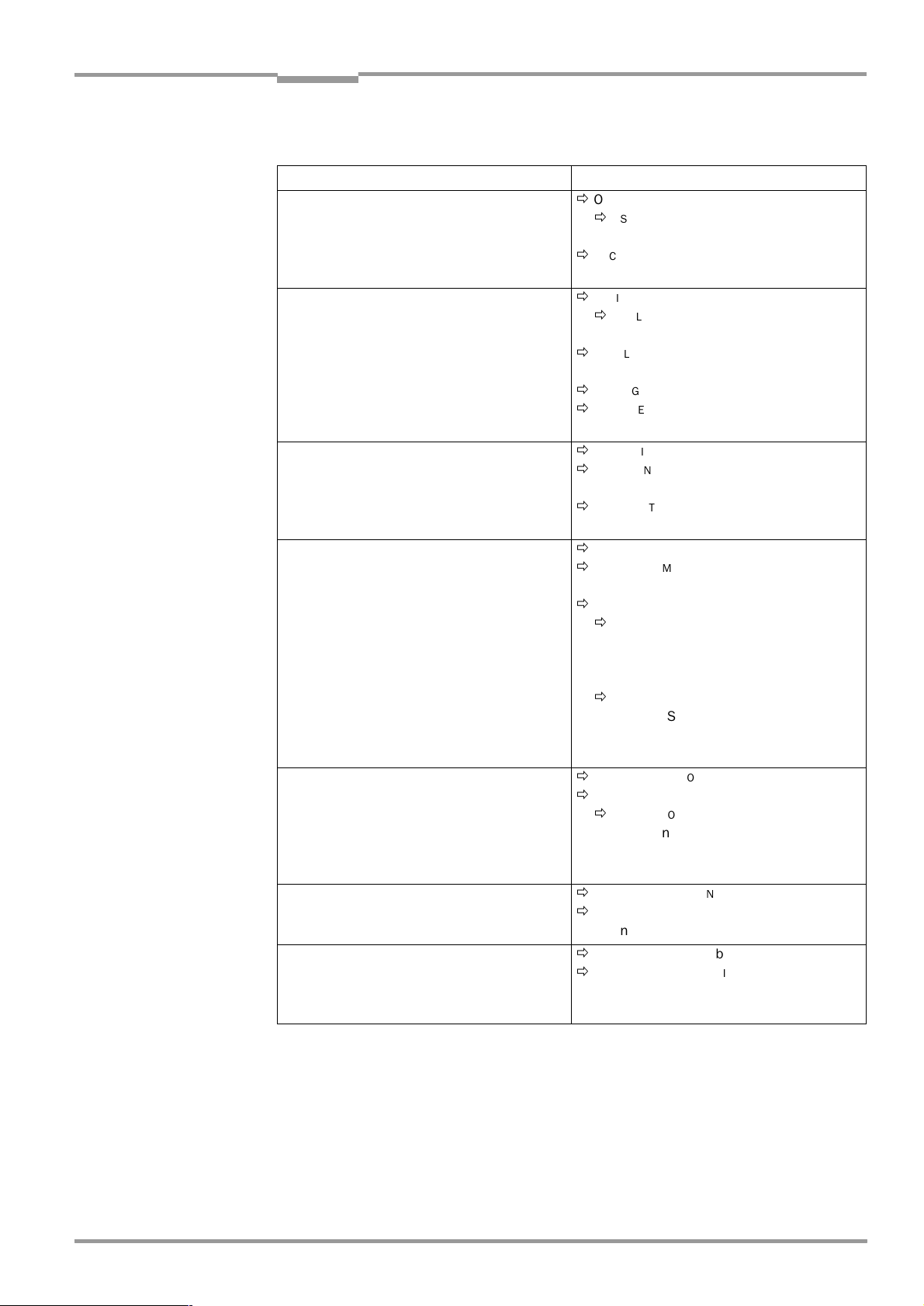
Operating Instructions Chapter 6
Operation
CLV 45x Bar Code Scanner
Setting up the oscillating mirror functions
Action Line scanner with oscillating mirror
1. Select the "Oscillating with constant maximum
amplitude" operating mode (identical
deflection ranges at changeover of the
distance configurations/focal positions)
– or –
2. Select "Oscillating with variable amplitude"
mode
(Deflection range can be selected for each
distance configuration at a changeover of the
distance configurations/focal positions)
– or –
O
Ö
SCILLATING MIRROR
O
Ö
SCILLATING MIRROR
– Oscillating mode
O
Ö
SCILLATING MODE
–Frequency
O
Ö
SCILLATING MIRROR
O
Ö
SCILLATING MIRROR
– Oscillating with variable amplitude
O
Ö
SCILLATING MODE
–Frequency
R
Ö
EADING CONFIGURATION
D
Ö
ISTANCE CONFIGURATIONS
– Oscillating mirror amplitude
3. Select "Fixed position" mode
– or –
O
Ö
SCILLATING MIRROR
O
Ö
SCILLATING MIRROR
– Fixed position
F
Ö
IXED POSITION
– Stationary position CW
4. Select "One-Shot" mode
O
Ö
SCILLATING MIRROR
O
Ö
SCILLATING MIRROR
– One-Shot
ONE-S
Ö
Ö
P
HOT
HASE
1
–Mirror Speed
– Start Position
– Distance configuration (No.)
P
HASE
2
Ö
–Mirror Speed
– Start position
– Distance configuration (No.)
5. With One-Shot: Select trigger source
O
Ö
SCILLATING MIRROR
ONE-S
Ö
T
Ö
RIGGER MODE
HOT
– Reading Trigger Pulse or
– "Sensor 2" switch input or
– Serial interface
6. At One-Shot and trigger source
"Sensor 2" switching input:
Select function for switching input
7. Select instant of activity of the "Oscillating
with ..." operating mode
D
Ö
EVICE CONFIGURATION
A
Ö
SSIGNMENT SENSOR
– One-Shot
O
Ö
SCILLATING MIRROR
O
Ö
SCILLATING MIRROR ACTIVE
–Continuous
– During reading gate
Table 6-5: Guide: Parameterizing the oscillating reading mirror functions
tab card
tab card
tab card
tab card
tab card
tab card
tab card
2
tab card
Explanation of oscillating mirror functions
"Oscillating with fixed amplitude" operating mode
The oscillating mirror deflects the scan line up to the maximum deflection range of
±
40 CW (corresponding to ± 20°).
8 009 139/K949/06-06-2002© SICK AG · Division Auto Ident · Germany · All rights reserved
Fig. 6-3
displays the scheme at a reading from above.
6-9
Page 62

Chapter 6 Operating Instructions
Operation
CLV 45x Bar Code Scanner
"Oscillating with Variable Amplitude" operating mode
The deflection range can be parameterized separately for each of the maximum of 8
distance configurations/focal positions. The limitation of the deflection range for fast applications ensure that the scan line only sweeps areas that contain bar codes during the time
available. At the same time this allows an almost constant scan line density on the object.
Fig. 6-4
shows the application at a reading from above.
Constant
oscillating
j
frequency
0
j
0
Scan line density depending on object height
Fig. 6-3: "Oscillating with fixed amplitude" operating mode
Constant
oscillating
frequency
Scan line density equal, independant of object height
Limitation of the
deflection range
(CW value)
6-10
Fig. 6-4: "Oscillating with variable amplitude" operating mode
©
SICK AG · Division Auto Ident · Germany · All rights reserved 8 009 139/K949/06-06-2002
Page 63

Operating Instructions Chapter 6
Conventionally required reading range
Reduced reading range through One-Shot function
Line scanner
Line scanner
with oscillating
mirror
R
e
a
d
i
n
g
r
a
n
g
e
R
e
a
d
i
n
g
r
a
n
g
e
CLV 45x Bar Code Scanner
Operation
"Fixed position" operating mode
The CLV parks the oscillating mirror at the desired position. 10 CW correspond to –20°, and
90 CW to +20° (
Fig. 4-8, Page 4-6
). In the default setting, the fixed position is set to 50 CW
(angle of deflection of 105°). The oscillating mode is switched off.
"One-Shot" mode
In the "One-Shot" mode the oscillating mirror only performs one specific oscillating movement per reading interval. This movement consists of a forward phase and a return phase.
The start position of the scan line, the mirror speed and the valid distance configuration can
be parameterized separately for each phase. The end position of the one phase forms the
start position of the other phase.
Fig. 6-5
shows an example for the application in object
tracking. During the forward phase, the front of the object that moves towards the oscillating
mirror is swept once by the scan line from top to bottom in accordance with the conveyor
speed. Multiple focus position switchovers are not necessary as the required reading range
(DOF) is much smaller than with the line scanner.
Chapter 10.7.2 Calculating the start position and mirror speed for the forward and return phase of the One-Shot function,
Page 10-37
explains how the start position and mirror speed are calculated for a given con-
veyor speed.
Possible trigger sources for One-Shot:
•
"Sensor 2" switching input
•
Command string (via serial interface)
•
Start of the reading interval
Fig. 6-5: One-Shot: Object tracking (bar code read from front)
D t
0
D t
1
8 009 139/K949/06-06-2002© SICK AG · Division Auto Ident · Germany · All rights reserved
6-11
Page 64

Chapter 6 Operating Instructions
Operation
CLV 45x Bar Code Scanner
b) Parameterizing the reading trigger source
Action Settings
1. Reading pulse: Select source for start
2. At pulse source "Sensor Input 1":
Select debouncing and response at first
trigger
3. For pulse source "Serial interface":
Select trigger character
4. Pulse source "Free-running":
Select timeout
5. Reading pulse: Select source for end
Table 6-6: Guide: Parameterizing the reading pulse source
D
Ö
EVICE CONFIGURATION
E
Ö
DIT READING TRIGGER
– Sensor input active high or
– Sensor input active low or
– Serial interface or
– Free-running with timeout
E
Ö
DIT READING TRIGGER
D
Ö
EBOUNCING SENSOR
– Standard or
–Fast
F
Ö
IRST TRIGGER
– Dynamic or
– Static
E
Ö
DIT READING TRIGGER
S
Ö
ERIAL INTERFACE
– Standard trigger or
– Single character
E
Ö
DIT READING TRIGGER
END OF
Ö
–Timeout
E
Ö
DIT READING TRIGGER
END OF
Ö
– By reading pulse source or
–Timer
LABEL/FREE-RUNNING
READING INTERVAL
tab card
c) Parameterizing the laser timeout
Action Settings
1. Select duration for laser-timeout
– or –
2. De-activate laser timeout
(Laser diode always active at pulsing
irrespective of the pulse duration)
Table 6-7: Guide: Parameterizing the laser timeout
D
Ö
EVICE CONFIGURATION
E
Ö
DIT READING TRIGGER
L
Ö
ASER TIMEOUT
– Duration
L
Ö
ASER TIMEOUT
– Click on the I
(de-activated)
NTERVAL ACTIVE
d) Parameterizing the evaluation characteristics
•
Select the decoder type Ö C
•
Enable the code type for evaluation
ODE CONFIGURATION
ODE CONFIGURATION
Ö
C
tab card Ö "Decoder"
tab card Ö "Codes" and
"Edit codes"
•
Activate the code comparison Ö D
•
Teach-in mode for the match code 1 via "Sensor 2" switching input" Ö D
RATION
tab card Ö "Teach-in"
•
Specify the output instance of the read result
EVICE CONFIGURATION
Ö
D
tab card Ö E
EVICE CONFIGURATION
DIT READING TRIGGER
tab card Ö "Code comparison"
Ö Output at "Good Read".
tab card
check box
EVICE CONFIGU
-
6-12
©
SICK AG · Division Auto Ident · Germany · All rights reserved 8 009 139/K949/06-06-2002
Page 65

Operating Instructions Chapter 6
CLV 45x Bar Code Scanner
Operation
Number of bar
codes
per object
1. Number n = 1
2. Number n > 1:
–Same code
type
–Contents
different or
identical
3. Number n > 1:
– Code type
different
–Contents
different or
identical
Table 6-8: Guide: Settings to be carried out for evaluating identical bar codes
Line scanner Line scanner with oscillating mirror
Stationary/moving conveyor object Stationary conveyor object Moving conveyor object
C
Ö
ODE CONFIGURATION
C
Ö
ODE POSITION
– De-activate "Compare"!
C
Ö
ODE POSITION
– Activate "Compare"!
N
Ö
UMBER OF CODES
– Minimum
– Maximum
C
Ö
ODE POSITION
– De-activate "Compare"!
N
Ö
UMBER OF CODES
– Minimum
– Maximum
tab card
C
Ö
ODE CONFIGURATION
C
Ö
ODE POSITION
– De-activate "Compare"!
C
Ö
ODE POSITION
– Activate "Compare"!
N
Ö
UMBER OF CODES
– Minimum
– Maximum
C
Ö
ODE POSITION
– De-activate "Compare"!
N
Ö
UMBER OF CODES
– Minimum
– Maximum
e) Parameterizing the output characteristics
Result status
•
Define function of result status output of "Result 1" and "Result 2" switching outputs:
EVICE CONFIGURATION
Ö
D
•
Define function of result status output and activity of beeper:
EVICE CONFIGURATION
Ö
D
tab card Ö "Edit result outputs"
tab card Ö "Edit result outputs"
tab card
C
Ö
ODE CONFIGURATION
C
Ö
ODE POSITION
– Activate "Compare"!
N
Ö
UMBER OF CODES
– Minimum
– Maximum
D
Ö
EVICE CONFIGURATION
E
OPC
Ö
DIT
– Label distance
– Length increment vector
– Angle increment vector
SPATIAL PARAMETERS
tab card
tab card
Main Data Interface general
•
Target of the read result Ö H
•
Filter read result Ö D
•
Sort reading result Ö D
•
Mask reading result Ö D
EVICE CONFIGURATION
OST INTERFACE
ATA STRINGS
ATA STRINGS
Ö "Destination of result data strings"
tab card Ö "Odette filter"
tab card Ö "Output sequence sort"
tab card Ö "Format mask"
Host interface
•
Arrangement in data network Ö D
•
Active physical interface Ö H
•
Communication parameters Ö H
•
Protocol ÖH
OST INTERFACE
Ö "Interface protocol"
EVICE CONFIGURATION
OST INTERFACE
OST INTERFACE
Ö "Data format"
Function of the CAN interface (alternative)
See the
operating instructions “Application of the CAN interface“
edition)
Data output string of host interface
•
Select contents of header, separator and terminator Ö D
format"
•
Position of separator in data output string Ö D
put"
Ö "CLV Arrangement"
Ö "Data format"
(no. 8 009 180, English
ATA STRINGS
ATA STRINGS
tab card Ö "Separator out-
tab ca rd Ö "Outp ut
8 009 139/K949/06-06-2002© SICK AG · Division Auto Ident · Germany · All rights reserved
6-13
Page 66

Chapter 6 Operating Instructions
Operation
CLV 45x Bar Code Scanner
•
Set wrong read format Ö D
ATA STRINGS
tab card Ö "Wrong read format", "Number of
characters" and "Error string"
•
If necessary, parameterize/activate test string Ö D
•
Parameterize special functions Ö D
ATA STRINGS
ATA STRINGS
tab card Ö "Test string"
tab card Ö "Specials"
f) Parameterizing the auxiliary interface function
UXILIARY INTERFACE
•
A
tab card
6.4.4 Configuring the CLV with Auto Setup
Auto Setup enables the reading and code configurations of the CLV to be adapted automatically to the existing read situation. The following conditions must be fulfilled for the
execution:
•
One bar code (code type, code length)
•
Fixed reading distance
•
No transport movement (static reading)
The CLV determines the code type, code length, the optimum focal position and the most
favorable scanning rate for the bar code presented. This takes place in Free running mode
with the standard decoder even if the SMART decoder may have been preselected beforehand for the Reading mode. Once Auto Setup has been completed successfully, the CLV
copies the parameter values determined to its parameter record. All other code types and
code lengths are disabled for further readings. If Auto Setup was not completed successfully, the parameter record is not changed. In Auto Setup the CLV does not read a Pharmacode or an EAN or UPC attachments. It does not react to an external reading pulse.
Auto Setup can be activated in three different ways in the CLV:
•
By means of the CLV-Setup user interface
•
By presenting Profile bar code No. 10 on the card supplied to the optical interface
(reading window)
Chapter 10.5.1 Activate Auto Setup with Profile bar code, Page 10-28
See
•
By means of a command string (via the serial interface)
Chapter 10.6 Configuring the CLV with command strings, Page 10-33
See
.
.
While Auto Setup is running, the CLV outputs the step-by-step changes made to the parameter values in the search mode as well as the determined diagnostic data via the terminal
interface in the form of a list. The list can be displayed, for example, in the terminal emulator
of CLV-Setup. Once Auto Setup has been completed, appropriate error messages are output for diagnosed malfunctions in the event of a no read.
6-14
Explanation Auto Setup procedure
1. The CLV moves across the entire focal position range in steps of 25 mm from
F = 200 mm to 1 200 mm at a scanning frequency of 600 Hz. It evaluates the reading
quality of 100 scans at each focal position.
2. When it reaches the part of the focal position range with the highest reading quality, the
CLV determines 5 positions from which it then mathematically calculates the maximum
reading quality and the focal position.
3. The CLV approaches this calculated focal position and performs a verification read.
4. If the reading quality is >75 %, the CLV increases its scanning frequency in steps of
100 Hz, starting at 400 Hz, up to 1 000 Hz. Once again, it evaluates the reading quality
©
SICK AG · Division Auto Ident · Germany · All rights reserved 8 009 139/K949/06-06-2002
Page 67

Operating Instructions Chapter 6
CLV 45x Bar Code Scanner
Operation
of 100 scans for each step. If the reading quality is lower, the CLV changes further
parameter values internally.
5. The CLV performs verification reads around the scanning frequency with the highest
reading quality at a scanning frequency lying 50 Hz above and 50 Hz below it.
6. It then copies the optimum scanning frequency, the focal position, as well as the code
type and code length in its parameter record.
Activating Auto Setup by means of the CLV-Setup user interface
In CLV-Setup, Auto Setup can be started by selecting the appropriate menu path, via the
terminal emulator or as an executable device function (interactively). We recommend
starting the Auto Setup by means of the terminal emulator since the progress display is
better.
Preparing Auto Setup
1. Switch on the supply voltage of the AMV/S 40 connection module (of the CLV).
After the start the CLV confirms the successful self-test with a beeper sound and shortly
afterwards starting of the reading mode is signaled by two consecutive sounds. The
"Device Ready" LED lights up.
Line scanner with oscillating mirror:
In the Auto Setup mode the CLV behaves in the following manner:
– in “Oscillating“ mode (default setting: oscillating with a fixed amplitude), the CLV shuts
off oscillation and positions the scan line under the angle CW = 50 (corresponding to
an angle of deflection of 105°). This position cannot be altered.
– in “One-Shot“ mode, the CLV also positions the scan line under the angle CW = 50.
– in “Set Position“ mode, the scan line’s selected position remains unchanged.
2. Upload the current parameter record from the CLV with CLV-Setup (the parameter
records initially contains the factory default settings).
CLV-Setup displays the values in the tab cards of the user interface.
3. Auto Setup overwrites important values in the current parameter record of the CLV.
Save the existing parameter record as a configuration file "*.scl" in CLV-Setup before
you change the parameter recordings (refer to
Chapter 6.4.1 Configuring the CLV by
means of the CLV-Setup user interface, Page 6-4).
Carrying out the Auto Setup
1. Click on in the toolbar.
The terminal emulator is then opened. The CLV is in the Reading mode.
2. Present the application-specific bar code to the CLV at the maximum reading distance
for the application. Take the limit values of the CLV into consideration (refer to the
reading field diagrams in
Chapter 10.2 Specification diagrams, Page 10-2
In order to avoid surface reflections, rotate the bar code towards the CLV approximately
15° away from the vertical axis (refer to
3. Click on the A
UTO SETUP
radio button under D
Fig. 4-7, Page 4-5
EVICE MODE
The CLV aborts reading mode. The "Device Ready" LED is extinguished.
The CLV then starts Auto Setup and temporarily activates the standard decoder. The
scan line appears when the "Laser On" LED lights up.
4. The CLV then runs Auto Setup and continuously displays the changes to the parameter
values in the terminal emulator.
Fig. 6-6
contains an example of this.
5. The CLV confirms that Auto Setup has been completed successfully by outputting two
consecutive acoustic signals via the beeper and activating the "Result" LED for 100 ms
8 009 139/K949/06-06-2002© SICK AG · Division Auto Ident · Germany · All rights reserved
).
).
.
6-15
Page 68

Chapter 6 Operating Instructions
Operation
CLV 45x Bar Code Scanner
(default setting). To begin with it only overwrites the appropriate parameter values in the
RAM.
The CLV returns to the Reading mode with the decoder parameterized for this purpose.
The "Device Ready" LED lights up. The R
EADING MODE
radio button in the terminal emulator is not, however, displayed as the active device mode again.
The CLV only evaluates the presented code type and length in further readings.
6. Uploading from the CLV To do so, click on in the toolbar.
CLV loads the current parameter record from the RAM of the CLV and displays the new
values in the tab cards.
7. Carry out the download to the CLV. To do so, click on in the toolbar.
OWNLOAD PARAMETERS
The D
8. Confirm the dialog box with the saving option P
dialog box is opened.
ERMANENT
.
The CLV saves the changes made to the parameter record permanently in the EEPROM.
9. Close the terminal emulator.
6-16
With:
FocPos = Focal position
Step = Motor step for focal position adjustment
Amp = Amplifier setting
ScanFreq = Scanning frequency
ReadRate = Reading quality
CodeType = Code type
CodeLen = Code length
CodeStr = Data contents of the bar code
Fig. 6-6: CLV-Setup: Displaying the course of the Auto Setup in the terminal emulator
Terminating Auto Setup by the CLV in the event of a no read
If the CLV was not able to execute Auto Setup successfully, it terminates the search mode
after the last increase made to the parameter values by outputting a long acoustic signal via
the beeper.
Depending on the reason for Auto Setup being terminated, it outputs one of the following
error messages via the terminal interface:
©
SICK AG · Division Auto Ident · Germany · All rights reserved 8 009 139/K949/06-06-2002
Page 69

Operating Instructions Chapter 6
CLV 45x Bar Code Scanner
Operation
No valid co de found
"
Cancel Auto Setup
"
" (No valid bar code found or reading quality under 75 %)
" (Auto Setup terminated)
– or –
More than one code found
"
Cancel Auto Setup
“
" (Auto Setup terminated)
"
The current parameter record in the CLV does not change.
The CLV returns to the Reading mode with the decoder parameterized for this purpose.
The "Device Ready" LED lights up.
Repeating the Auto Setup
1. Click on the R
EADING MODE
radio button under
DEVICE MODE
.
The CLV switches to the Reading mode.
2. Click on A
UTO SETUP
under D
EVICE MODE
again.
The CLV starts the Auto Setup.
3. If Auto Setup is unsuccessful again, check whether the CLV is able to read the bar code
correctly (reading distance, tilt, more than one bar code in the reading area).
Terminating Auto Setup prematurely
It is here not possible to abort Auto Setup.
¾
In order to prevent parameter values in the RAM of the CLV from being overwritten,
move the bar code away from the reading area and wait for the CLV to output an error
message (Auto Setup must not supply valid settings).
Check the determined parameter values in CLV (after permanent saving)
1. Switch the supply voltage of the connection module (of the CLV) off and on again.
2. Carry out an upload from the CLV. To do so, click on in the toolbar.
3. View the values in the R
EADING CONFIGURATION
Only one code type may be active in the C
ODE CONFIGURATION
ODE CONFIGURATION
and C
tab cards.
tab card.
Note The CLV does not enter any real values in the parameter record for the parameters "Mini-
mum distance" or "Minimum bar width" as it is not able to determine any absolute dimensions. The values displayed in the R
CONFIGURATIONS
dialog box do not, therefore, reflect the actual situation.
EADING CONFIGURATION
tab card or the D
ISTANCE
Checking the determined read and code configurations
Once Auto Setup has been completed successfully, check the CLV settings as follows:
1. Click in the toolbar.
The terminal emulator is then opened. The CLV is in the Reading mode.
2. Click on the P
ERCENTAGE EVALUATION
radio button under D
EVICE MODE
.
The dialog box for prompting the distance configuration is opened.
3. Click on the relevant distance configuration for reading the bar code.
4. Confirm the dialog box with "OK".
The CLV starts the percentage evaluation and displays the reading quality of each set
of 100 scans continuously (refer to
Chapter 6.5.2 Percentage evaluation, Page 6-21
5. Present the application-specific bar code at the teach-in distance (at the minimum and
maximum reading distance if the bar code in the application is in a variable reading
range).
).
8 009 139/K949/06-06-2002© SICK AG · Division Auto Ident · Germany · All rights reserved
6-17
Page 70

Chapter 6 Operating Instructions
Operation
CLV 45x Bar Code Scanner
6. Monitor the display of the reading quality in the terminal emulator. This should be
between 70 and 100 %.
6.5 Operating modes and output of the read result
The following CLV operating modes/functions can be selected in CLV-Setup:
Standard operating mode:
•
Reading mode
For startup
•
Percentage evaluation
•
Adjusting mode
For adapting to the reading situation
•
Auto Setup (automatic adaptation to reading conditions)
(refer to
•
Profile programming (configuration)
(refer to
•
Parameterization (configuration)
(refer to
Page 6-4)
•
Teach-in match code 1/activate match code comparison with "Sensor 2" switching input (refer to
switching input, Page 10-40)
•
Show CP limits
Chapter 6.4.4 Configuring the CLV with Auto Setup, Page 6-14)
Chapter 10.5.2 Profile progamming, Page 10-30)
Chapter 6.4.1 Configuring the CLV by means of the CLV-Setup user interface,
Chapter 10.9.1 Triggering the Teach-in match code 1 via the "Sensor 2"
For monitoring purposes/correcting faults
•
Displaying and editing operating data
•
Reading diagnosis
•
Monitor host interface
•
Auxiliary input
•
Self-test
6.5.1 Reading mode (Standard mode)
The CLV performs a self-test after it has been switched on. It is then set to the Reading
mode and confirms this by outputting two consecutive acoustic signals via the beeper. In
the default setting the "Sensor 1" switching input is the (external) trigger source of the
reading pulse. The read result is output by the CLV at the end of the reading pulse via the
host interface (default) and terminal interface.
The read result of the terminal interface can be displayed in the CLV-Setup terminal emulator. Prerequisite for display is that the CLV terminal interface must be set to the R
DIAGNOSIS
mode. This mode is selected for the default setting. The read result of the terminal
EADING
interface has a fixed, invariable format.
The Reading mode can be called up by choosing V
IEW
in the menu bar or via the terminal
emulator.
6-18
©
SICK AG · Division Auto Ident · Germany · All rights reserved 8 009 139/K949/06-06-2002
Page 71

Operating Instructions Chapter 6
CLV 45x Bar Code Scanner
Operation
Line scanner with oscillating mirror:
In reading mode the CLV deflects the scan line in the default setting with a frequency of 1 Hz
around the position CW = 50 at a maximum angle of ±20°. 50 CW corresponds to a light
emission under 105°.
Displaying the read result in the terminal emulator
1. Click on in the toolbar.
The terminal emulator dialog box is opened.
2. Click on the R
3. Present the bar code pattern from
bar code pattern from
EADING MODE
Fig. 6-2, Page 6-4
radio button under D
Fig. 6-1, Page 6-3
to the CLV 451 and activate the reading pulse.
The "Laser On" LED lights up. The scan line then appears. Also refer to
EVICE MODE
.
to the CLV 450 respectively the
Chapter 6.3.1
Starting up the line scanner/line scanner with oscillating mirror with the factory default
setting, Page 6-3.
4. Terminate reading pulse.
The CLV outputs an acoustic signal via the beeper to indicate that the reading result is
displayed in the window of the terminal emulator. The "Result" LED lights up for a
duration of 100 ms (default setting).
Fig. 6-7
shows two examples of the output of a read result: “Good Read“ and “No Read“.
The read result comprises the data contents of the bar code(s) and the reading diagnosis
Fig. 6-8
data.
Read, and
explains the structure and function of the reading diagnosis data for Good
Fig. 6-9
for No Read.
Note The CLV only outputs several bar codes in the read result if the parameterized minimum and
maximum number of bar codes is >1, and several bar codes have been presented. The
number of bar codes to be read/output for each read port can be selected in the C
FIGURATION
tab card in the N
UMBER OF CODES
section.
ODE CON
-
Fig. 6-7: CLV-Setup: Displaying the read result of the terminal interface in the terminal emulator
8 009 139/K949/06-06-2002© SICK AG · Division Auto Ident · Germany · All rights reserved
6-19
Page 72

Chapter 6 Operating Instructions
Successful reading (Good Read):
TT=_340 ms MG=_31 % n=_1 AK=1
0123412345
C39 _99% St=0 CP=_49 CL=10 CA=177 CS=176 CK=99 DI=R
With:
1st. line : TT = Duration of the reading interval
MG = Temporal mean value of the identification quality
n = Number of recognized codings
AK = No. of the used distance configuration
2nd. line: 0123412345 = Data contents of the bar code
3rd. line: C39 = ID: Code type Code 39
_99% = Identification quality
ST = Read status (ST = 0: Good Read)
CP = Code position
CL = Code length (number of characters)
CA = Scan effort
CS = Code reliability
CK = Code continuity
DI = Decoding direction
(F = in scanning direction, R = against scanning direction)
Reading fault (No Read):
TT=__440 ms MG=_31 % n=_0 AK=1
no code!
With:
1st. line : TT = Duration of the reading interval
MG = Temporal mean value of the identification quality
n = Number of recognized codings
AK = No. of the used distance configuration
2nd. line: no code! = No. bar codes found!
Operation
CLV 45x Bar Code Scanner
Fig. 6-8: Read result of the terminal interface: Structure for “Good Read“
Fig. 6-9: Read result of the terminal interface: Structure for “No Read“
The read result of the host interface can also be displayed.
Chapter 6.5.7 Host interface monitoring, Page 6-26
structure of the read result in the default setting.
6-20
©
SICK AG · Division Auto Ident · Germany · All rights reserved 8 009 139/K949/06-06-2002
describes the procedure and the
Page 73

Operating Instructions Chapter 6
CLV 45x Bar Code Scanner
Operation
Triggering the reading pulse via the terminal emulator
In the default setting the "Sensor 1" switching input is the (external) trigger source of the
reading pulse. The reading pulse can also be triggered directly via the terminal emulator of
CLV-Setup for test purposes. To do so, a different trigger source must be selected temporarily in the CLV.
1. Select the D
2. Click on the E
The E
3. Click on the S
EVICE CONFIGURATION
DIT READING TRIGGER
DIT READING TRIGGER
ERIAL INTERFACE
tab card.
command button.
dialog box is opened.
radio button.
4. Confirm the dialog box with "OK".
5. Carry out the download to the CLV. To do so, click on in the toolbar.
OWNLOAD PARAMETERS
The D
6. Confirm the dialog box with the saving option T
dialog box is opened.
EMPORARY
.
The serial interface has been activated as the trigger source of the reading pulse and
is ready to receive appropriate commands.
7. Click on in the toolbar.
The terminal emulator dialog box is opened. The CLV is in the Reading mode.
8. Click on the SW-T
RIGGER ON
command button or press [F7].
CLV-Setup sends a start command to the CLV.
The "Laser On" LED lights up and the scan line appears.
9. Present the bar code pattern from
bar code pattern from
10. Click on the SW-T
Fig. 6-2, Page 6-4
RIGGER OFF
command button or press [F8].
Fig. 6-1, Page 6-3
to the CLV 451.
to the CLV 450 respectively the
CLV-Setup sends a stop command to the CLV.
The "Laser On" is extinguished. The CLV switches off the laser diode.
The CLV outputs an acoustic signal via the beeper to indicate that the reading result is
displayed in the window of the terminal emulator. The "Result" LED lights up for a duration of 100 ms (default setting).
6.5.2 Percentage evaluation
In the Percentage evaluation mode, the quality is assessed of the readings of bar codes
which are placed statically into the reading area of the CLV (no transport movement of the
object).
The CLV performs 100 scans in the Free-running mode and evaluates the reading quality.
It outputs the read results continuously every 2 s via the terminal interface. The read re-
sults can be displayed in the terminal emulator of CLV-Setup.
The standard decoder has to be set temporarily for the percentage evaluation.
The Percentage evaluation mode can be called up via V
IEW
in the menu bar or via the
terminal emulator.
Line scanner with oscillating mirror:
In the Percentage evaluation mode the CLV behaves in the following manner:
– in “Oscillating“ mode (default setting: oscillating with a fixed amplitude), the CLV shuts
off oscillation and positions the scan line under the angle CW = 50 (corresponding to
an angle of deflection of 105°). This position cannot be altered.
– in “One-Shot“ mode, the CLV also positions the scan line under the angle CW = 50.
– in “Set Position“ mode, the scan line’s selected position remains unchanged.
8 009 139/K949/06-06-2002© SICK AG · Division Auto Ident · Germany · All rights reserved
6-21
Page 74

Chapter 6 Operating Instructions
Operation
CLV 45x Bar Code Scanner
1. Select the C
2. Click on the S
ODE CONFIGURATION
TANDARD
radio button in the D
tab card.
ECODER
section.
3. Carry out the download to the CLV. To do so, click on in the toolbar.
OWNLOAD PARAMETERS
The D
4. Confirm the dialog box with the saving option T
dialog box is opened.
EMPORARY
.
The CLV operates with the standard decoder.
5. Click on in the toolbar.
The terminal emulator window opens. The CLV is in the Reading mode.
6. Click on the P
ERCENTAGE EVALUATION
radio button under D
EVICE MODE
.
The dialog box for selecting the distance configuration is then displayed.
7. Click on the distance configuration which corresponds to the reading distance of the
object.
(Default setting: No. 1, focal position F = 900 mm for CLV 450, F = 550 mm for
CLV 451).
8. Confirm the dialog box with "OK".
The "Device Ready" LED is extinguished. The CLV initiates the percentage evaluation
and outputs the reading results continuously. An example is shown in
9. Present the bar code pattern from
bar code pattern from
Fig. 6-2, Page 6-4
Fig. 6-1, Page 6-3
to the CLV 450 respectively the
to the CLV 451 and monitor the read results
Fig. 6-10.
in the terminal emulator window.
The "Result" LED provides additional optical information on the reading quality reached:
– LED extinguishes if the reading quality < 30 %
– LED flashes twice per second if the reading quality is 30 % ... 70 %
– LED flashes five times per second if the reading quality is 70 % ... 90 %
– LED lights up constantly, if reading quality > 90 %
6-22
Fig. 6-10: CLV-Setup: Displaying the percentage evaluation in the terminal emulator
The output format of the read result is the same as that of the Reading mode.
Fig. 6-8
explains the structure and function of the reading diagnosis data.
©
SICK AG · Division Auto Ident · Germany · All rights reserved 8 009 139/K949/06-06-2002
Page 75

Operating Instructions Chapter 6
CLV 45x Bar Code Scanner
Operation
Note Profile bar codes read by the CLV during the percentage evaluation do not cause any
changes to be made to the parameter record and do not, therefore, affect the reading
process either.
The match codes cannot be programmed (teach-in) in the Percentage evaluation mode. The
codes are entered in the D
EVICE CONFIGURATION
tab card. Match code 1 can, however, also
be programmed using the teach-in method.
6.5.3 Adjusting mode
The "Adjusting mode" enables the center of the scan line to be optimally positioned on the
bar code.
Chapter 4.3.3 Auxiliary functions for adjusting, Page 4-10
describes the procedure after the adjusting mode has been called up. The CLV does not output a read result in
this mode.
The Adjusting mode can be called up under V
IEW
, under T
OOLS
as a device function (in the
dialog box) or via the terminal emulator.
Line scanner with oscillating mirror:
In the Adjusting mode the CLV behaves in the following manner:
– in “Oscillating“ mode (default setting: oscillating with a fixed amplitude), the CLV shuts
off oscillation and positions the scan line under the angle CW = 50 (corresponding to
an angle of deflection of 105°). This position cannot be altered.
– in “One-Shot“ mode, the CLV also positions the scan line under the angle CW = 50.
– in “Set Position“ mode, the scan line’s selected position remains unchanged.
1. Click on in the toolbar.
The terminal emulator window opens. The CLV is in the Reading mode.
2. Click on the A
DJUSTING MODE
radio button under D
EVICE MODE
.
The "Device Ready" LED is extinguished. The CLV aborts the Reading mode and blanks
the scan line as of position CP = 50 to position CP = 100.
3. Click on the R
EADING MODE
radio button in order to terminate the Adjusting mode.
The CLV then returns to the Reading mode and the "Device Ready" LED lights up.
6.5.4 Show CP limits
In this mode, the CLV blanks certain parts of the scan line so that any limit values defined
for the active evaluation range of the scan line can be checked directly during parameterization. The restricted active evaluation range shortens the evaluation time for fast applications, for example, because the evaluation routine only has to take account of unblanked
parts of the scan line. The range is restricted by entering appropriate values for M
CODE POSITION
EADING CONFIGURATION
the R
and M
AXIMUM CODE POSITION
tab card.
in the E
DIT DISTANCE CONFIGURATIONS
INIMUM
dialog box in
"Show CP limits" is used to check whether the limit per activated distance configuration is
adapted distance-specifically for the selected setting at the focal position changeover
("Christmas tree effect"). The CLV does not output a read result.
"Show CP limits" can be called up under V
IEW
, under T
OOLS
as a device function (in the dialog
box) or via the terminal emulation.
Line scanner with oscillating mirror:
In the „Show CP limits“ mode the CLV behaves in the following manner:
– in “Oscillating“ mode (default setting: oscillating with a fixed amplitude), the CLV shuts
off oscillation and positions the scan line under the angle CW = 50 (corresponding to
an angle of deflection of 105°). This position cannot be altered.
8 009 139/K949/06-06-2002© SICK AG · Division Auto Ident · Germany · All rights reserved
6-23
Page 76

Chapter 6 Operating Instructions
Operation
CLV 45x Bar Code Scanner
– in “One-Shot“ mode, the CLV also positions the scan line under the angle CW = 50.
– in “Set Position“ mode, the scan line’s selected position remains unchanged.
The CLV blanks the scan line alternately as of the set value for CP
Fig. 6-11
for CP
max
.
shows an example of this. The changeover is carried continuously at a
and as of the set value
min
second interval. The part of the scan line that remains active for the reading procedure is
the section between the shielding of CP
Example:
Default setting: Evaluation set for the range of CP
The CLV blanks the line as of CP
CP
max
Active range
CP
min
Fig. 6-11: Appearance of scan line in the "Show CP-limits" mode
= 5 (short scan line) and as of CP
min
and the shielding of CP
min
=5 to CP
min
"Show CP limits"
.
max
=95.
max
max
Scan line 2
Scan line 1
= 95 (long scan line).
Proceed as follows to check the restricted evaluation range:
1. Click on in the toolbar.
The terminal emulator window opens. The CLV is in the Reading mode.
2. Click on the S
HOW
CP
LIMITS
radio button under D
EVICE MODE
.
The dialog box for prompting the distance configuration is opened.
3. Click the distance configuration for which the active evaluation range of the scan line
has been restricted (DC-specific).
The "Device Ready" LED is extinguished. The CLV aborts the Reading mode and blanks
the scan line alternately as described above as of CP
and CP
min
max
.
4. Use Steps 2 and 3 to check for each active distance configuration whether the bar code
is in the center of the range between the end of the shorter scan line (CP
end of the longer scan line (CP
) or, if there are several bar codes, to determine
max
) and the
min
whether the center of the field of all the codes is within the range.
5. If necessary, correct CP
6. Click on the R
EADING MODE
and CP
min
accordingly. Carry out a download to the CLV!
max
radio button to exit the S
HOW
CP
LIMITS
mode.
The CLV then returns to the Reading mode and the "Device Ready" LED lights up.
Note In th e Re adi ng mode, the CLV doe s not actu all y blank th e sc an line vis ually, but ins te ad takes
the values specified for the restricted evaluation range mathematically into account when
the data contents are decoded.
6-24
©
SICK AG · Division Auto Ident · Germany · All rights reserved 8 009 139/K949/06-06-2002
Page 77

Operating Instructions Chapter 6
CLV 45x Bar Code Scanner
Operation
6.5.5 Displaying and editing operating data
This function enables statistical operating data, which the CLV maintains in the form of counters during the reading procedure, to be sampled and reset.
The CLV does not output a read result in this mode.
1. Click in the toolbar.
The CLV aborts reading mode. The "Device Ready" LED is extinguished.
The O
PERATING DATA
dialog box is opened (
Fig. 6-12
).
2. After reading/resetting the desired counters, click on "OK" to confirm the dialog box.
The CLV then returns to the Reading mode and the "Device Ready" LED lights up.
Fig. 6-12: CLV-Setup: "Operating Data" dialog box
6.5.6 Reading diagnosis
Function of the terminal interface. In this mode the CLV outputs the data contents of all the
bar codes that were read - including those that, according to the evaluation criteria, were not
read properly and were thus incorrect - together with the associated reading diagnosis data
via the terminal interface. The number of bar codes output can, therefore, be higher than
the number of those that were sent via the host interface in the read result. In the default
setting this mode is selected for the terminal interface.
Fig. 6-7, Page 6-19
shows the corresponding output format of the terminal interface.
In the default setting the CLV does not output any reading diagnosis data via the host.
Should the reading diagnosis be not activated, it can be selected via the A
tab card.
8 009 139/K949/06-06-2002© SICK AG · Division Auto Ident · Germany · All rights reserved
UXILIARY INTERFACE
6-25
Page 78

Chapter 6 Operating Instructions
Operation
CLV 45x Bar Code Scanner
1. Select the R
EAD DIAGNOSTICS
option in the A
UXILIARY INTERFACE
list field.
2. Carry out the download to the CLV. To do so, click on in the toolbar.
OWNLOAD PARAMETERS
The D
3. Confirm the dialog box with the saving option P
dialog box is opened.
ERMANENT
.
The terminal interface is now set to the "Read diagnostics" mode.
6.5.7 Host interface monitoring
Function of the terminal interface. In this mode the CLV outputs the data traffic of its host
interface via the terminal interface. Repeat requests of the protocol driver and protocol-specific data, such as start and stop characters, are suppressed here (
Table 6-9).
Each data
string is displayed in a separate line on the screen.
Direction of data Output format Display on screen
CLV receives from host <STX> I data <CR> <LF> <ETX> I data
CLV sends to host <STX> O data <CR> <LF> <ETX> O data
Table 6-9: "Host interface monitoring" function
The “host interface monitoring“ is activated by means of the A
1. Select the M
ONITOR HOST INTERFACE
option in the A
UXILIARY INTERFACE
UXILIARY INTERFACE
list field.
tab card.
2. Carry out the download to the CLV. To do so, click on in the toolbar.
OWNLOAD PARAMETERS
The D
3. Confirm the dialog box with the saving option T
dialog box is opened.
EMPORARY
.
The terminal interface is then set to the "Monitor host Interface" until the CLV is switched
off again.
Displaying the data traffic of the host interface in the terminal emulator
The data traffic of the host interface can be displayed in the terminal emulator of CLV-Setup.
Table 6-13
shows an example of how the read result can be output.
1. Select the serial interface as the external trigger source for the reading pulse.
Refer to
Page
Chapter 6.51, „Triggering the reading pulse via the terminal emulator“
6-21
.
,
2. Click on in the toolbar.
The terminal emulator window opens. The CLV is in the Reading mode.
3. Click on the SW-T
RIGGER ON
command button or press [F7].
The scan line then appears.
4. Present the bar code pattern from
bar code pattern from
5. Click on the SW-T
Fig. 6-2, Page 6-4
RIGGER OFF
Fig. 6-1, Page 6-3
to the CLV 450 respectively the
to the CLV 451.
command button or press [F8].
CLV-Setup outputs the read result in the terminal emulator.
Example: "O 0123412345".
6-26
©
SICK AG · Division Auto Ident · Germany · All rights reserved 8 009 139/K949/06-06-2002
Page 79
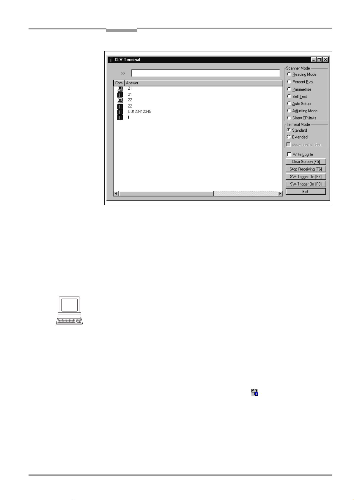
Operating Instructions Chapter 6
CLV 45x Bar Code Scanner
Operation
Fig. 6-13: CLV-Setup: Output of the read result of the host interface in the terminal emulator at the
beginning (in this case: O = Output)
Note If a large amount of data is being read in at high speed and with a high transmission rate,
the host interface’s data traffic may not longer be completely displayed on the terminal interface (display: " ... "). This is due to the slower transmission rate of the terminal interface
(9 600 bits/s).
In the default setting the CLV only sends the data contents of the bar code in the data output
string of the host interface.
The header, separator and terminator are empty.
Hint
The structure of the data output string of the host interface can be configured via the D
STRINGS
tab card. Up to 10 elements, consisting of constants and/or reading diagnosis data,
can be entered in the header, in the separator and in the terminator.
1. Select the D
2. Click on the H
DIT PARAMETER
The E
ATA STRINGS
EADER
tab card.
list field.
: TFH dialog box is opened.
3. Click on the desired constants or placeholders for the reading diagnosis data.
The selected elements appear in the text line at the top of the dialog box in the
sequence in which they were selected.
4. Confirm the dialog box with "OK".
5. Repeat this procedure for the separator and terminator.
6. Carry out the download to the CLV. To do so, click on in the toolbar.
OWNLOAD PARAMETERS
The D
7. Confirm the dialog box with the saving option P
dialog box is opened.
ERMANENT
.
The CLV outputs the selected elements in the data output string of the host interface
with the next read result.
ATA
8 009 139/K949/06-06-2002© SICK AG · Division Auto Ident · Germany · All rights reserved
6-27
Page 80

Chapter 6 Operating Instructions
Operation
CLV 45x Bar Code Scanner
6.5.8 Auxiliary input
Function of the terminal interface. In this mode the CLV accepts a bar code entered at the
terminal interface (via the keyboard or handheld scanner with decoder). It sends the bar
code to the host in a separate data string via its host interface. "No reads" can, therefore,
be corrected by transferring missing bar codes subsequently.
Chapter 10.9.2 Auxiliary input via terminal interface, Page 10-45
describes this function and
the associated procedure in greater detail.
6.5.9 Self-test
After the CLV has been switched on, it performs a self-test before it is initialized with the
parameter record. The test can be called up explicitly at any time via CLV-Setup. During the
self-test the CLV checks that its hardware components are functioning correctly. A final
message via the terminal interface provides information on the test result. The CLV does not
output a read result during the test routine.
1. Click on in the toolbar.
The terminal emulator window opens.
The CLV is in the Reading mode.
2. Click on the S
ELF TEST
radio button under D
EVICE MODE
.
The "Device Ready" LED is extinguished. The CLV cancels the Reading mode and starts
the test routine.
After a few seconds, the CLV outputs the encoded test result in the form of a code (refer
Fig. 6-14
to
3. To return to the Reading mode, click on the R
).
EADING MODE
radio button or close the
terminal emulator.
The CLV then returns to the Reading mode and the "Device Ready" LED lights up.
6-28
Fig. 6-14: CLV-Setup: Outputting the self-test result in the terminal emulator
©
SICK AG · Division Auto Ident · Germany · All rights reserved 8 009 139/K949/06-06-2002
Page 81

Operating Instructions Chapter 6
CLV 45x Bar Code Scanner
Operation
The code number "15 000" means that the self-test was completed successfully and that
no faults were diagnosed.
Chapter 8.3 Error messages, Page 8-2
lists the error key together with the associated
corrective measures.
6.5.10 Carrying out device functions of the CLV in the dialog box
CLV-Setup allows a number of device functions of the CLV to also be executed in the dialog
box. CLV-Setup prompts the user to carry out specific actions and provides information on
the progress of the function being executed.
The following functions are available:
•
Auto Setup
•
Match code teach-in
•
Show CP limits
•
Adjusting mode
•
Analyse scanner network (only for application of the CAN interface)
OOLS
¾
Select the desired function under T
EVICE FUNCTIONS
, D
in the menu bar.
– or –
Press [F2].
XECUTE DEVICE FUNCTIONS
The E
Select the desired function in the E
dialog box is opened.
XECUTE
menu.
CLV-Setup starts the function and, where appropriate, prompts the user to carry out the
necessary actions.
Fig. 6-15
shows an example of the dialog box that appears after Auto Setup has been
started.
Fig. 6-15: CLV-Setup: Dialog box for executing the Auto Setup
8 009 139/K949/06-06-2002© SICK AG · Division Auto Ident · Germany · All rights reserved
6-29
Page 82

Chapter 6 Operating Instructions
Operation
CLV 45x Bar Code Scanner
6.6 Messages of the CLV
The CLV outputs system, warning and error messages in English in response to the actions
carried out by the user for the firmware. The messages are output in plain text via the
terminal interface only.
6.6.1 Displaying messages
Proceed as follows in order to display messages on the screen of the PC in the CLV-Setup
user interface:
1. Click on in the toolbar.
The terminal emulator window opens.
2. Click on the E
XTENDED
radio button in the T
The CLV then outputs messages in response to events that occur while the bar code is
being read. The messages are only output in the extended mode of the terminal emulator!
6.6.2 System messages
System messages confirm that an action has been carried out successfully, e. g. changing
the operating mode. No further messages are required.
Chapter 10.3 System messages, Page 10-19
ERMINAL MODE
section.
explains the contents of the messages.
6.6.3 Warnings
Warning messages indicate that it was not possible to perform an action or that the values
set for the parameters can cause an error while the bar code is being read.
Table 6-10
lists the warning messages in alphabetical order together with the associated
corrective measures.
Message Meaning Remedy
"Warning: Master Timeout" The duration of the selected master timeout is
too short
Table 6-10: Warning
Optimize the master timeout using the D
CONFIGURATION
CLV-Setup. Download to the CLV!
(also refer to the special
"Master/Slave with bar code scanners of CLV
Series", No. 8 007 675, English edition
6.6.4 Error messages
Error messages indicate the following types of error:
•
A device defect
•
Incorrect parameter settings
•
Errors during data transmission to the host
Chapter 8.3 Error messages, Page 8-2
lists the messages in alphabetical order together
with the associated corrective measures.
EVICE
tab card in the user interface of
Technical information
)
6-30
©
SICK AG · Division Auto Ident · Germany · All rights reserved 8 009 139/K949/06-06-2002
Page 83

Operating Instructions Chapter 6
CLV 45x Bar Code Scanner
Operation
6.7 Switching off the CLV
1. If the parameter record was modified in CLV-Setup or was only stored temporarily in
CLV via a download, the parameter record must be stored permanently in the CLV by
choosing the P
ERMANENT
2. Save the parameter record as a configuration file "*.scl" in CLV-Setup.
3. Switch off the supply voltage of the AMV/S 40 connection module or pull the plug of the
CLV out of the connection module.
The last parameter record stored permanently in the CLV connection module remains valid.
We recommend that you print out the configuration file in order to archive the parameter
record.
1. Click on in the toolbar.
The P
RINT FILE
dialog box is opened.
2. Enter a comment in the input field in order to assign the printout to the CLV.
Confirm your entry with "OK".
RINT
The P
dialog box for configuring the printer is then displayed.
3. Edit the dialog box correspondingly and confirm.
CLV-Setup prints out the actual configuration file in the form of a table.
storage option.
8 009 139/K949/06-06-2002© SICK AG · Division Auto Ident · Germany · All rights reserved
6-31
Page 84

Chapter 6 Operating Instructions
Operation
CLV 45x Bar Code Scanner
Notes
6-32
©
SICK AG · Division Auto Ident · Germany · All rights reserved 8 009 139/K949/06-06-2002
Page 85

Operating Instructions Chapter 7
Line scanner Line scanner with oscillating mirror
Clean here
CLV 45x Bar Code Scanner
Maintenance
7
Maintenance
7.1 Maintenance during operation
A clean reading window is required to maintain the full reading performance of the CLV.
It is therefore advisable to check the reading window regularly for dirt, in particular in rough
operating environments (dust, abrasion, moisture, fingerprints).
Laser radiation may cause damage to your eyes!
The CLV operates with a Class 2 red-light laser. The retina can be damaged if you look too
long into the laser beam.
¾
Never look directly into the laser beam (comparable with sunlight).
¾
Switch off the device for the duration of cleaning.
¾
Never look into the reading window while the device is in operation.
Damage to the reading window!
The reading window consists of glass. The reading performance is reduced by scratches and
streaks on the reading window.
¾
Use a mild detergent without power admixture.
¾
Avoid scratching and scouring movements on the reading window.
Cleaning the reading window
¾
Clean the reading window at regular intervals with a mild detergent without powder
admixture, for example an anti-static window liquid detergent.
faces to be cleaned.
Use a soft lintfree cloth for cleaning.
¾
If required, also clean the LEDs of the device rear.
Fig. 7-1
shows the sur-
Fig. 7-1: Cleaning the reading window
8 009 139/K949/06-06-2002© SICK AG · Division Auto Ident · Germany · All rights reserved
7-1
Page 86

Chapter 7 Operating Instructions
Maintenance
CLV 45x Bar Code Scanner
Cleaning the further optically effective surfaces:
¾
In the case of external reading cycle generation and/or object height detection with sensors (e. g. reflection photoelectric switches) clean their optically effective surfaces
Fig. 7-2
(
Fig. 7-2: Cleaning the external optical sensors (reading clock generator, object height detection)
). Dirt and impurity can cause faulty switching performance.
7.2 Maintenance
The CLV operates maintenance-free. Its self-monitoring functions allow long, trouble-free
operation.
The CLV outputs device and function errors in the form of messages via the terminal interface. As far as they exist in clear text, they are displayed on the screen of the PC in extended
mode of the terminal emulator of the CLV-Setup user interface. Further errors are displayed
as a numerical combination in the 4th field from the bottom left in the status bar (Refer to
Chapter 8.3 Error messages, Page 8-2).
7.3 Disposal
After having shut down unusable or irreparable devices dispose of them in a manner which
does not damage the environment.
1. Observe the country-specific guidelines on waste disposal.
2. Dismantle the CLV housing.
3. Remove the electronic modules and connection cable.
4. Remove the glass pane of the reading window and dispose of the glass as waste glass.
5. Dispose of the chassis frame and cover in the disposal for zinc diecasting.
6. Dispose of electronic modules and connection cables as hazardous waste.
At present SICK AG does not take back devices which have become unusable or
irreparable.
7-2
©
SICK AG · Division Auto Ident · Germany · All rights reserved 8 009 139/K949/06-06-2002
Page 87

Operating Instructions Chapter 8
CLV 45x Bar Code Scanner
Troubleshooting
8
Troubleshooting
8.1 Overview of the possible errors and malfunctions
8.1.1 Mounting errors
•
•
•
8.1.2 Faults during the electrical installation
•
•
8.1.3 Parameterization errors
•
•
CLV aligned incorrectly to the object with the bar code (e. g. blanking)
Reading-pulse sensor positioned incorrectly
With focal position changeover: Sensor for object height detection positioned
incorrectly
Interfaces on the CLV wired incorrectly (wiring error in AMV/S 40)
Host interface on AMV/S 40 configured incorrectly
Functions not adjusted to local conditions, e. g. communication parameters on the host
interface are set incorrectly
Technical limits of the device exceeded, e. g. relationship between the scanning
frequency and the reading distance
8.1.4 Faults during operation
•
Laser timeout for laser diode expired
•
Device fault (hardware/software)
8.2 Monitoring error and fault signs
The CLV is self-monitoring:
•
After the supply voltage has been switched on, the CLV automatically carries out a selftest, in which it checks important hardware components, before it is initialized (parameter record loaded and device functions initialized). The self-test can be repeated at
any time after the reading mode has been canceled.
For the call-up refer to the
•
If the CLV detects an error during the self-test/self-diagnosis, it outputs the error status
ST = 3 via the host interface. Prerequisite: The error status is enabled for transfer. In
the default setting transfer is disabled.
The CLV displays the diagnosed error in code form as a numerical combination in the
4th field from the bottom left in the status bar of the CLV-Setup user interface via the
terminal interface (
•
While it is in operation, the CLV constantly monitors the laser diode and speed of the
polygon mirror wheel. In addition, a watchdog circuit reacts to incorrect device states.
•
A timer automatically de-activates the laser diode in reading mode at the "Sensor input"
and "Serial interface" trigger mode 10 minutes (default setting) after the beginning
of a lasting reading pulse. However, it does not end the reading interval. The CLV outputs the following message via the terminal interface: "
reading pulse is to be terminated by resetting the trigger signal. The next reading pulse
re-activates the laser diode.
Table 8-1
Chapter 6.5.9 Self-test, Page 6-28
).
Laser safety timeout"
.
. The
8 009 139/K949/06-06-2002© SICK AG · Division Auto Ident · Germany · All rights reserved
8-1
Page 88

Chapter 8 Operating Instructions
Troubleshooting
CLV 45x Bar Code Scanner
8.3 Error messages
The CLV only outputs error messages of the firmware in clear text via its terminal interface
in English. Others are output as numerical combinations in the status bar of the CLV-Setup
user interface.
For warnings refer to
Displaying messages:
Proceed as follows in order to display the messages on the PC screen in the CLV-Setup user
interface:
1. Click on in the toolbar.
The terminal emulator window opens.
2. Click the E
Message Meaning Possible cause Remedy
"CLV SYS-Failure: xxx"
011
012
013
051
061
071
091...095
201...215
"EEPROM Check fault,
default parameters loaded"
"EEPROM - reading fault"
"EEPROM - writing fault"
"Focus table inconsistent:
defaults loaded"
RAM error
RAM error
RAM error
Mirror wheel speed
out of tolerance
Mirror interval
out of tolerance
Error laser shutter
Error focus adjustment
DSP error
The CLV has diagnosed a
system error.
The "Device Ready" LED
does not light up or
extinguishes.
The CLV tries a new system
start.
The CLV has diagnosed an
irregularity in the EEPROM
and downloads the entire
default setting to the RAM
instead of the last permanently stored parameter
record.
The CLV cannot download the
parameter record stored in
the EEPROM to the RAM.
The CLV cannot write the current parameter record from
the RAM to the EEPROM.
The CLV has diagnosed an
irregularity in the internal
reference table for the focus
positions selected by the
user.
It therefore downloads the
default setting of the distance
configurations.
Table 8-1
contains a list of the messages in alphabetical order.
Chapter 6.6.3 Warnings, Page 6-30
XTENDED
radio button in the T
Defective device If the system error occurs repeat-
Defective device Contact the SICK Service depart-
Defective device Contact the SICK Service depart-
Defective device Contact the SICK Service depart-
Defective device Contact the SICK Service depart-
ERMINAL MODE
.
section
edly after the CLV is restarted:
Contact the SICK Service department
ment
ment
ment
ment
Table 8-1: Error messages output via the terminal interface
©
8-2
SICK AG · Division Auto Ident · Germany · All rights reserved 8 009 139/K949/06-06-2002
Page 89

Operating Instructions Chapter 8
Troubleshooting
CLV 45x Bar Code Scanner
Message Meaning Possible cause Remedy
"Host – receive fault"
The host has requested the
data output string last sent by
the CLV three times; NAK has
been issued with each
attempt.
•
Receipt of the host set
incorrectly
•
Data transfer interrupted e. g.
by cable break
•
Check the host
•
Check connecting cables and
monitor data transfer of the
host interface. To do so, select
upload from the CLV by using
the CLV-Setup user interface,
select the A
UXILIARY INTERFACE
tab card and select H
FACE
in the M
ONITOR
list field.
OST INTER
Download to the CLV!
Call up the terminal emulator.
"Host – transfer too slow"
In the CLV, data is available
for output faster than it is
transferred to the host.
•
Baud rate too low
•
Incorrect protocol type
selected
•
Protocol timeout too long
Check the configuration of the
host interface
for the reading pulse frequency
"Host – transmit fault"
The CLV cannot correctly
receive the data sent by the
host
•
Host interface of the CLV configured incorrectly
•
Data transfer interrupted e. g.
by cable break
•
Check the CLV and host.
•
Check connecting cables and
monitor data transfer of the
host interface. To do so, select
upload from the CLV by using
the CLV-Setup user interface,
A
UXILIARY INTERFACE
and select H
the M
ONITOR
tab card
OST INTERFACE
in
list field. Download
to the CLV!
Call up the terminal emulator.
"Master/slave – trigger too soon"
The new reading pulse for the
master is received before its
timeout has elapsed
Timeout for the master is too long Check the coordination between
reading pulse and timeout. To do
so, select upload from the CLV by
using the CLV-Setup user interface, D
EVICE CONFIGURATION
card and change the M
in the CLV A
OUT
RRANGEMENT
tab
ASTER TIME
section.
Download to CLV!
"More than one code found"
Auto Setup was not successful
More than one bar code was
presented to the CLV
Repeat the Auto Setup. Ensure
that only one bar code is in the
visible range of the CLV (in
particular with oscillating mirror!)
"No polls?"
Network operation:
the CLV is waiting for polls by
the CLX 200 network controller
•
Data connecting cables interrupted
•
CLX 200 not ready
•
Incorrect device number
parameterized
•
Inadvertently parameterized
for network mode
•
Check cables
•
Switch on CLX 200
•
Device number: Parameterize
01 to 31
•
Check the configuration of the
host interface.
To do so, select upload from
the CLV by using the CLVSetup user interface, H
INTERFACE
tab card and check
the settings in the I
PROTOCOL
section.
OST
NTERFACE
Download any changes to the
CLV!
-
-
Table 8-1: Error messages output via the terminal interface
8 009 139/K949/06-06-2002© SICK AG · Division Auto Ident · Germany · All rights reserved
8-3
Page 90

Chapter 8 Operating Instructions
Troubleshooting
CLV 45x Bar Code Scanner
Message Meaning Possible cause Remedy
No valid code found
"
"
The Auto Setup was not successful
No bar code was presented to
the CLV or the reading quality did
not reach 75 %
Repeat the Auto Setup.
Ensure that the bar code lies
within the reading range of the
CLV.
Oscillating mirror faulty
"
“
The CLV cannot operate the
oscillating mirror or cannot
Defective device Contact the SICK Service depart-
ment
initialize the mirror
Slave string faulty
"
" Data transfer error between a
slave and the master
Data connecting cables interrupted
If the error occurs repeatedly,
check the data connecting cables
between all CLVs.
Wrong number of slaves
"
" During the master timeout,
the master receives more or
fewer reading results from the
slaves than expected from
the number of slaves entered.
•
Parameterized number of slaves does not agree with the
number of connected slaves
•
Check the entered number of
slaves. To do so, select upload
from the CLV by using the CLVSetup user interface, D
CONFIGURATION
tab card and
EVICE
check the number of slaves in
the CLV A
RRANGEMENT
section.
Download any changes to the
CLV!
•
Master timeout too short
•
As above, but check the timeout defined for the master
•
•
Data connection between the
Check the connecting cables
slaves interrupted
"Wrong parameters - master/
slave"
After selection of the master/
slave function, individual
parameter values, which are
not compatible with the automatic settings defined for this
function by the CLV, were
changed subsequently.
Deviations from the following
values:
•
Test string: no (slaves)
•
Auxiliary input: no (slaves)
•
Pulse: Serial interface
or switching input
•
RK 512: without reaction
Use the CLV- Setup user interface
to check that the settings on the
D
ATA STRING
T
ERMINAL INTERFACE
D
EVICE CONFIGURATION
and H
,
OST INTERFACE
,
,
tab cards are
correct.
message
Table 8-1: Error messages output via the terminal interface
8-4
©
SICK AG · Division Auto Ident · Germany · All rights reserved 8 009 139/K949/06-06-2002
Page 91

Operating Instructions Chapter 8
Troubleshooting
CLV 45x Bar Code Scanner
8.4 ST error status in the read result of a bar code
Value Meaning Possible cause Remedy
0 "Good Read" – Not applicable
1 Incorrect check digit The check digit calculated by the CLV
during the reading process does not
match that in the bar code.
2 No bar code of the enabled code type
conforming to the evaluation criteria
•
No bar code in the CLV's reading area
during the reading pulse
found
•
Code type/length in the CLV not
enabled for decoding
•
Reading window obstructed/dirty
3 Device fault Defective device Call up the self-test! (refer to
5 Required number of identical multiple
reads for the bar code not reached
•
Conveyor speed of the object too high
•
Scanning frequency is too low
•
In case of ladder-type positioning of bar
code relative to conveyor direction:
code height (bar length) too small
•
Print quality poor
6Master:
Number of slave read results does not
match the parameterized number of
slaves
•
Parameterized number of slaves does
not match actual number of slaves
available
•
Timeout for the master is too short
•
Data connection between slaves and/or
the master has been interrupted
7 The source of the read result is the
auxiliary input via the terminal interface
The bar code was not detected by the
reading function of the CLV, but was
entered subsequently with the auxiliary
function of the terminal interface and
transferred to the host in a separate data
string.
9The "O
UTPUT FILTER
activated for the code comparison.
" function is
The scanned object does not have a bar
code that matches the specified set code
The CLV has detected valid bar codes.
However, these do not match the
active set code(s).
func-
AThe C
HECK MAX. NUMBER OF CODES
tion is active.
The number of valid bar codes
detected by the CLV in Reading mode
exceeds that specified under N
OF CODES
: M
AXIMUM
UMBER
.
One object in a set of objects with a con-
stant number of bar codes, for example,
contains more bar codes than defined in
the application.
It repeatedly outputs the defined error
string until the number specified under
N
UMBER OF CODES
: M
D The "Code 32" evaluation option is
activated for Code 39. The CLV is
attempting to interpret 6-digit C39 bar
codes as C32 bar codes (output as
INIMUM
is reached.
The read 6-digit bar code is not a C32 bar
code.
The CLV outputs the defined error string
instead
9-digit decimal values).
Check whether the check digits in the
bar code field and generated by the
print process are correct
•
Synchronize the pulse of the CLV
with the occurrence of a bar code in
the reading range
•
Parameterize the code configuration correctly
•
Check the reading window
Chapter 6.5.9 Self-test, Page 6-28). If
result ≠ 000: Contact the SICK Service department
•
Check the conveyor speed
•
Adjust the scanning frequency
•
Check code height.
•
Check print quality
•
Check the entered number of
slaves
•
Check the master timeout setting
•
Check the cables between the
slaves and the master
–
–
This message is used to indicate
errors on the objects (e. g. check
whether objects are homogeneous:
mixed with incorrect objects).
–
Table 8-2: Meaning of the ST error status in the read result
8 009 139/K949/06-06-2002© SICK AG · Division Auto Ident · Germany · All rights reserved
8-5
Page 92

Chapter 8 Operating Instructions
Troubleshooting
CLV 45x Bar Code Scanner
8.5 Troubleshooting
The following aids are required for troubleshooting purposes using the tables below:
•
These operating instructions
•
Tool
•
Measuring tape (up to 2000 mm)
•
A digital measuring device (ammeter/voltmeter)
•
A PC running "CLV-Setup"
•
RS 232 data connection cable (Pin 2 and Pin 3 transposed), e. g. No. 2 014 054
8.5.1 General malfunctions: CLV not ready
Fault Possible cause Remedy
1. The "Device Ready" LED
does not light up.
The "Result 1" switching output (default setting: "Device
ready) is not outputting a
pulse.
After the supply voltage has
been switched on
(10 ... 30 V DC):
•
The CLV has no operating
voltage
•
The CLV diagnosed a device
error during the self-test
During operation:
•
The CLV is not in "Reading"
mode
•
The CLV has deactivated the
laser diode 10 min. (default
setting) after the start of the
current reading pulse
(pulse type: sensor input/
serial interface)
•
Check the wiring
(power connector fitted
securely to the AMV/S 40
connection module).
Measure voltage at Pin 1 and
Pin 5.
•
Switch the CLV off and on
again. Does the LED light up?
If not, contact the SICK
Service department.
•
Return to Reading mode
using the CLV-Setup user
interface.
(refer to Chapter 6.5.1
Reading mode (Standard
mode), Page 6-18).
•
Terminate reading pulse.
Check the reading pulse
function. Pulse again or
adjust the laser timeout
duration by means of the
CLV-Setup user interface
(refer to Chapter 6.4.3 Guide
to parameterization,
Page 6-8).
8-6
Table 8-3: Troubleshooting: Restoring operation (Reading mode)
©
SICK AG · Division Auto Ident · Germany · All rights reserved 8 009 139/K949/06-06-2002
Page 93

Operating Instructions Chapter 8
Troubleshooting
CLV 45x Bar Code Scanner
8.5.2 Malfunction in Reading mode: Reading pulsing errors
The "Device Ready" LED lights up. If not, refer to measures in
Table 8-3, Page 8-6
Fault Possible cause Remedy
1. Pulsing type:
Sensor input
(external sensor).
•
Sensor not connected or
connected to incorrect
switching input
•
Connect sensor to "Sensor
1" switching input.
Check sensor wiring (refer to
Chapter , Page 5-2
The CLV cannot be pulsed:
– The "Laser On" LED does
not light up
– The scan line does not
appear
•
If sensor su p pli e d by the CLV:
Sensor not connected to
frame potential
•
Incorrect reading pulse source parameterized on the CLV
re output signal on sensor
•
Insert jumper between Pin 5
and Pin 15
•
Select checking by means of
the CLV-Setup user interface,
D
EVICE CONFIGURATION
card, click on the E
T
RIGGER
Sensor input selected?
(active high: Reading pulse
starts when power applied)
•
Photoelectric switch not
aligned to the reflector
•
Align sensor. Check
functioning
(photoelectric proximity
switch or inductive sensor not
dampened)
2. Pulse type:
Serial interface
The CLV cannot be pulsed:
– The "Laser On" LED does
not light up
– The scan line does not
appear
•
Incorrect reading pulse
source parameterized on the
CLV
•
Select checking by means of
the CLV-Setup user interface,
D
EVICE CONFIGURATION
card, click on the E
T
RIGGER
M
ODE
face selected?
S
ERIAL INTERFACE
Triggering type selected
correctly?
•
•
The CLV is not receiving any
command strings to start the
reading interval.
Check data connection to
host.
Select checking by means of
the CLV-Setup user interface,
H
OST INTERFACE
D
ATA FORMAT
correct interface type (hard-
ware) and data format
selected?
I
NTERFACE PROTOCOL
Are the correct start and stop
characters selected?
.
). Measu-
tab
DIT READING
command button.
tab
DIT READING
command button.
section: Is serial inter-
section:
tab card.
section: Are the
section:
Table 8-4: Troubleshooting: Reading pulsing errors in Reading mode
8 009 139/K949/06-06-2002© SICK AG · Division Auto Ident · Germany · All rights reserved
Use the CLV-Setup user inter-
face to check the host com-
mand strings: Select the
T
ERMINAL INTERFACE
Select M
INTERFACE
ONITOR HOST
function (refer to
tab card.
Chapter 6.5.7 Host interface
monitoring, Page 6-26
).
Download temporarily to the
CLV
8-7
Page 94

Chapter 8 Operating Instructions
Troubleshooting
CLV 45x Bar Code Scanner
Fault Possible cause Remedy
3. CLV does not react to an
external signal that ends the
reading pulse (sensor input,
serial interface)
Incorrect end of reading
pulse parameterized in CLV
Select checking by means of
the CLV-Setup user interface,
D
EVICE CONFIGURATION
click on the E
command button. E
DING INTERVAL
tab card,
DIT READING TRIGGER
ND OF REA
-
section:
Is "Generated by trigger
source" selected?
Table 8-4: Troubleshooting: Reading pulsing errors in Reading mode
8-8
©
SICK AG · Division Auto Ident · Germany · All rights reserved 8 009 139/K949/06-06-2002
Page 95

Operating Instructions Chapter 8
Troubleshooting
CLV 45x Bar Code Scanner
8.5.3 Malfunctions in Reading mode: Result output errors
The "Device Ready" LED lights up. If not, refer to measures in
Table 8-3, Page 8-6
here: Number of bar codes: 1
Fault Possible cause Remedy
1.The "Result" LED (default
setting: "Good Read") does
not light up at the end of the
reading pulse.
– The "Result 2" switching
output (default setting:
"Good Read") does not
output a pulse
– The CLV outputs the status
ST = 2 in the read result on
the host interface (if ST is
enabled for the separator;
this is not selected in the
default setting)
•
Read not successful, since
there was no bar code in the
reading area during the
reading pulse
•
Scan line positioned
incorrectly
•
Evaluation range of the scan
line is limited unfavorably (CP
values)
•
Bar code presented at
incorrect reading distance
•
Incorrect focal position
selected in the distance configuration
•
At dynamic focal position
changeover: Trigger source
parameterized incorrectly
•
Synchronize read with presence of an object in the reading field (refer to
Chapter 8.5.2 Malfunction in
Reading mode: Reading
pulsing errors, Page 8-7
•
Align CLV.
Is bar code at center of scan
line?
Check the reading quality
wi th the CL V-Setu p user inter face. To this purpose call up
P
ERCENTAGE EVALUATION
to
evaluation, Page 6-21
•
Select checking by means of
the CLV-Setup user interface,
D
EVICE CONFIGURATION
card, click on the D
CONFIGURATION
ton. Are the min. and max.
code position values selected correctly? Check with
S
HOW
Chapter 6.5.4 Show CP
limits, Page 6-23
•
Check whether reading distance of bar code is in the
specified reading range?
•
Select checking by means of
the CLV-Setup user interface,
D
EVICE CONFIGURATION
card, click on the D
CONFIGURATION
ton. Does the focal position
match the distance of the object?
•
Select checking by means of
the CLV-Setup user interface,
R
EADING CONFIGURATION
TRIGGER SOURCE
a) Trigger source: "Sensor 2"
switching input:
Check functional assignment
and connection of sensor
(refer to
.
)
(refer
Chapter 6.5.2 Percentage
)
tab
ISTANCE
command but-
CP
(refer to
LIMITS
)
tab
ISTANCE
command but-
, F
OCUS
section.
Fig. 5-5, Page 5-8
).
Table 8-5: Troubleshooting: Result output errors in Reading mode
8 009 139/K949/06-06-2002© SICK AG · Division Auto Ident · Germany · All rights reserved
8-9
Page 96

Chapter 8 Operating Instructions
Troubleshooting
CLV 45x Bar Code Scanner
Fault Possible cause Remedy
1. The "Result" LED does not
light up at the end of the reading pulse.
(Default setting: "Good
Read")
– Continued –
•
At dynamic focal position
changeover:
Trigger source parameterized
incorrectly
– Continued –
•
b) Trigger source: "Serial
interface":
Check the data connection to
the host.
Use the CLV-Setup user interface to check the host command strings: Select the
T
ERMINAL INTERFACE
Select the M
INTERFACE
function (refer to
tab card.
ONITOR HOST
Chapter 6.5.7 Host interface
monitoring, Page 6-26).
Download temporarily to CLV!
c) Trigger source: "Timer":
Check the changeover time
setting.
•
•
The bar code is tilted strongly
with respect to the scan line
(large tilt)
Select CLV-Setup user interface: C
ODE CONFIGURATION
card, D
ECODER
se ction. Selec t
tab
the SMART decoder.
Download to CLV!
•
•
The reading angles at which
the bar code appears to the
CLV are too large
Select CLV-Setup user interface: C
ODE CONFIGURATION
card, D
ECODER
section.
tab
Select the standard decoder.
Download temporarily to the
CLV!
Call up P
TION
ERCENTAGE EVALUA
, select distance configu-
-
ration.
Monitor reading quality
(reading quality > 70 %!).
If necessary, realign CLV and/
or reconfigure the distance
configuration.
If "OK", choose SMART
decoder. Download to the
CLV!
•
•
Bar code is in total reflection
zone
Optimize CLV alignment
(scan line should strike the
bar code at an angle of approx. 15°)
Check the reading quality
with the CLV-Setup user interface. Call up P
EVALUATION
(refer to
ERCENTAGE
Chapter 6.5.2 Percentage
evaluation, Page 6-21)
8-10
Table 8-5: Troubleshooting: Result output errors in Reading mode
©
SICK AG · Division Auto Ident · Germany · All rights reserved 8 009 139/K949/06-06-2002
Page 97

Operating Instructions Chapter 8
Troubleshooting
CLV 45x Bar Code Scanner
Fault Possible cause Remedy
1. The "Result" LED does
not light up at the end of the
reading pulse. (Default
setting: "Good Read")
– Continued –
•
Evaluation criteria for bar
code not set correctly
•
Select CLV-Setup user interface: C
ODE CONFIGURATION
card, C
ODES
section.
Enable all code types (except
Pharmacode), set code
lengths to F
. Download
REE
tab
temporarily to CLV!
Call up P
TION
ERCENTAGE EVALUA
. Code type and length
-
are displayed in the read
result.
Enable the determined code
ODES
type in the
section
C
and disable all other types.
Enter the code length in the
code type tab under F
IXED
.
Download to CLV!
•
•
Bar code quality inadequate
Check: Sufficient idle zones
present?
Print contrast sufficient?
Specified print tolerances
exceeded?
Select checking by means of
the CLV-Setup user interface,
R
EADING CONFIGURATION
card, S
EGMENTATION
tab
section.
Is "Start/Stop automatic"
selected?
Carry out read with faultless
reference code as a test.
2. The CLV is not transferring
any read results to the host.
•
Reading pulse is not
functioning correctly
•
Refer to Chapter 8.5.2 Mal-
function in Reading mode:
Reading pulsing errors,
Page 8-7
•
•
Wiring fault in data
connection
•
Voltage level incorrect
•
Host interface in CLV parameterized incorrectly
Check wiring as shown in
Fig. 5-2, Page 5-5.
•
Measure voltages.
•
Select checking with CLVSetup user interface, H
INTERFACE
FORMAT
tab card, D
: section. Correct inter-
ATA
OST
face type (hardware) and
data format selected?
NTERFACE
I
3. The CLV transfers the status
ST = 3 to the host in the
read result.
(If ST is enabled for the
separator; this is not
The CLV has diagnosed a
device error in the self-test
Check settings in
PROTOCOL
section.
Switch the CLV off and on again.
Does the "Device Ready" LED
light up?
If not, contact the SICK Service
department.
selected by default setting)
Table 8-5: Troubleshooting: Result output errors in Reading mode
8 009 139/K949/06-06-2002© SICK AG · Division Auto Ident · Germany · All rights reserved
8-11
Page 98

Chapter 8 Operating Instructions
Troubleshooting
CLV 45x Bar Code Scanner
Fault Possible cause Remedy
4. The data content of the bar
code output by the CLV is
incorrect or incomplete.
•
The data format on the host
interface is parameterized
incorrectly in the CLV
•
Select checking by means of
the CLV-Setup user interface,
H
OST INTERFACE
FORMAT
tab card, D
section.
ATA
Are the values correct?
•
The CLV suppresses the last
character in the bar code
•
Select checking by means of
the CLV-Setup user interface,
C
ODE CONFIGURATION
Click the E
DIT CODES
tab card.
command button.
Select the tab card for the
respective code type.
Is the output check digit
enabled? Change if
necessary.
Download to CLV!
Table 8-5: Troubleshooting: Result output errors in Reading mode
8.5.4 Malfunctions in Reading mode: Errors in the result status output
The "Device Ready" LED lights up. If not, refer to measures in
Table 8-3, Page 8-6
Fault Possible cause Remedy
1. The "Result 1" (default setting: Device Ready) and "Result 2" (default setting: Good
Read) switching outputs are
not outputting any pulses
•
Event of the assigned
function for outputting the
result status of the reading
does not occur in the reading
process.
•
Incorrect switching behavior
parameterized in CLV
•
Not applicable
•
Select checking by means of
the CLV-Setup user interface,
D
EVICE CONFIGURATION
card. Click on the E
OUTPUTS
Are the outputs set to „No“
inverted output?
Change, if necessary.
Download to CLV!
2. The beeper is not confirming
the output of the read result.
(Default setting: "Good
Read")
Beeper de-activated Select checking by means of
the CLV-Setup user interface,
D
EVICE CONFIGURATION
B
section: "Beeper active"
EEPER
selected?
Table 8-6: Troubleshooting: Errors in the result status output in Reading mode
.
tab
DIT RESULT
command button.
tab card,
8-12
©
SICK AG · Division Auto Ident · Germany · All rights reserved 8 009 139/K949/06-06-2002
Page 99

Operating Instructions Chapter 8
Troubleshooting
CLV 45x Bar Code Scanner
8.5.5 Malfunctions in Reading mode: Oscillating mirror operation errors
The
"Device Ready" LED lights up. If not, refer to measures in
Table 8-3, Page 8-6
Fault Possible cause Remedy
1. The oscillating mirror does
not move.
•
Incorrect operating mode
parameterized in the CLV
•
Se l ect c h ec kin g by m ean s of
the CLV-Setup user interface, O
card, O
section.
Is
XED AMPLITUDE
WITH VARIABLE AMPLITUDE
selected?
2. The oscillating mirror oscillates with the maximum
deflection (40 CW), although a variable amplitude
of e. g. 10 CW is set in the
Distance Configuration 1.
•
O
SCILLATING MODE WITH FIXED
AMPLITUDE
parameterized in
the CLV by mistake
•
The oscillating amplitude is
parameterized in the wrong
distance configuration
(here: No. 2)
•
From the O
ROR
O
AMPLITUDE
Download to CLV!
•
Se l ect c h ec kin g by m ean s of
the CLV-Setup user interface, D
Click on the D
GURATION
Is the amplitude value set in
the correct distance configuration (here: No. 1)?
•
•
Distance configuration not
changed over
Se l ect c h ec kin g by m ean s of
the CLV-Setup user interface, D
tab card.
Function Sensor 2: Is focal
control changeover selected?
Connect sensor to "Sensor
2" switching input.
Check sensor wiring (refer to
Fig. 5-5, Page 5-8
Measure output signal of
sensor
3. One-Shot:
The One-Shot function
cannot be triggered
(sensor correctly connected to the "Sensor 2"
switching input)
Trigger source incorrectly parameterized and/or "Sensor 2"
switching input has not been
assigned this function.
Select checking by means of
the CLV-Setup user interface,
O
SCILLATING MIRROR
Trigger mode OK?
Select D
card.
Function Sensor 2: Is trigger
One-Shot selected?
Table 8-7: Troubleshooting: Oscillating mirror errors in Reading mode
.
SCILLATING MIRROR
SCILLATING MIRROR
OSCILLATING MODE WITH FI
or
OSCILLATING
MIR
SCILLATING
tab card select the
SCILLATING WITH VARIABLE
mode.
EVICE CONFIGURATION
command button.
EVICE CONFIGURATION
EVICE CONFIGURATION
ISTANCE CONFI
).
tab card.
tab
-
-
.
-
tab
8 009 139/K949/06-06-2002© SICK AG · Division Auto Ident · Germany · All rights reserved
8-13
Page 100

Chapter 8 Operating Instructions
Troubleshooting
CLV 45x Bar Code Scanner
8.5.6 Malfunctions: Configuration errors (parameterization)
Fault Possible cause Remedy
1. Auto Setup:
The CLV does not read the
presented, applicationspecific bar code (no
confirmation from beeper)
2. Profile programming:
CLV does not read the
presented Profile bar code
(no confirmation by the
beeper)
•
CLV not in "Auto Setup"
mode
•
If Auto Setup is started with
Profile bar code No. 10:
Wait time of 5 s after powerup has been exceeded
•
Bar code presented at incorrect reading distance
•
Bar code is in total reflection
zone
•
Bar code quality not
adequate
•
Wait time of 5 s after powerup has been exceeded
•
Wait time of 10 s after the
first Profile bar code
was presented has been
exceeded
•
In Reading mode: CLV not
pulsed
•
Check: Does the "Device
Ready" LED light up? If so,
the CLV is in "Reading" mode
again.
CLV-Setup user interface:
Call up the Auto Setup
function again via the V
pull-down menu
•
Switch the CLV off and on
again.
Present the Profile bar code
No. 10 within 5 s.
Then the applicationspecific
bar code.
•
Check whether the reading
distance of the bar code lies
within the specified reading
range?
•
Optimize bar code alignment
(scan line should strike the
bar code at a skew of approx.
15 )
•
R
efer to Fault 1, Table 8-5,
Page 8-9
•
Switch the CLV off and on
again.
Present Profile bar code within 5 s.
•
Once the f irst Prof ile b ar co de
has been read successfully,
present the next bar code
within 10 s, etc.
•
Pulse the CLV accordingly
and present the first Profile
bar code. Present the next
bar code within 10 s, etc.
).
IEW
8-14
Table 8-8: Troubleshooting: Configuration errors (parameterization)
8.6 SICK Support
If a system error occurs repeatedly (
correct an error using the above measures, the CLV may be defective. The CLV does not
have any system components whose functionality can be restored by the user after a failure.
Please contact our local SICK office or subsidary:
•
The telephone and fax numbers are listed on the
¾
Do not send the device to the SICK service without first contacting us.
©
SICK AG · Division Auto Ident · Germany · All rights reserved 8 009 139/K949/06-06-2002
"CLV SYS failure: xxx", xxx = 000...299
back page
of this manual.
) or if you cannot
 Loading...