

Page 1
CLV42x
Bar Code Scanner
Standard Line
OPERATING INSTRUCTIONS
Page 2
Software versions
Operating Instructions
CLV 42x bar code scanner
Software versions
Software/Tool Function Version
CLV 420/421/422 Firmware V1.70 O078
CLV Setup User software (Windows-based) V 4.1 O508
CLV Setup Help Online help (HTML) V 4.1 O508
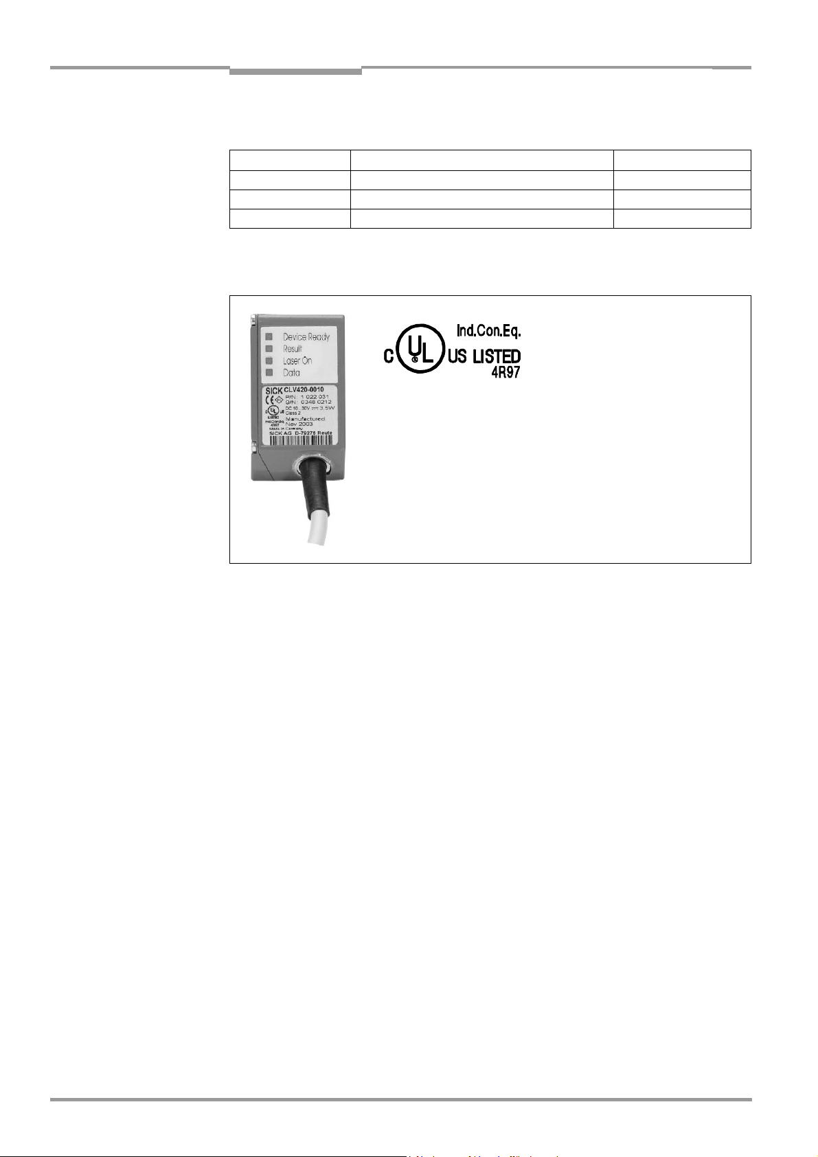
UL Certification
The CLV 42x is UL certificated when a class 2 power
supply according to UL 1310 is used.
Valid only with corresponding product marking on the
nameplate.
Copyright
Copyright © 2004
SICK AG Waldkirch
Auto Ident, Reute Plant
Nimburger Strasse 11
79276 Reute
Germany
Trademarks
TM
Windows 95
Explorer
TM
are registered trademarks or trademarks of the Microsoft Corporation in the USA
TM
/98
, Windows NTTM, Windows 2000TM, Windows XPTM and Internet
and other countries.
Latest manual version
For the latest version of this manual (PDF), see www.sick.com.
I-2 © SICK AG · Division Auto Ident · Germany · All rights reserved 8 009 981/O078/16-08-2004
Page 3

Operating Instructions
CLV 42x bar code scanner
Quick Finder
CLV 42x bar code scanner
Quick Finder
• Scope of delivery
– Chapter 3.1.1 Scope of delivery, Page 3-1
• IMPORTANT!
– Chapter 2 Safety information, Page 2-1
• Installing device at reading station
– Chapter 4 Installation, Page 4-1
• Electrical connection of device
– Chapter 5 Electrical connection, Page 5-1
• Overview of device and its functions
– Chapter 3 Product description, Page 3-1
– Chapter 6.2 Default settings, Page 6-1
– Chapter 6.5 Operating modes and outputting the reading result, Page 6-14
– Chapter 9 Technical data, Page 9-1
• Starting device with default settings
– Chapter 6.3 Quick start, Page 6-3
• Installing "CLV Setup" user software to PC
– Chapter 10.4 Installation and operating instructions for the PC-based "CLV Setup"
program, Page 10-7
• Adapting device to reading application
– Chapter 6.4 Configuration (parameterizing), Page 6-4
• Troubleshooting
– Chapter 8 Troubleshooting, Page 8-1
• Finding information
– Table of contents, Page E-5
– Index, Page 10-49
8 009 981/O078/16-08-2004 © SICK AG · Division Auto Ident · Germany · All rights reserved I-3
Page 4

Quick Finder
Operating Instructions
CLV 42x bar code scanner
Installation procedure (overview)
Reading pulses via switching input "Sensor 1" (default setting)
1. Check scope of delivery for completeness.
2. Install the CLV at the reading station and align it with an object possessing a bar code.
3. Install the CDB 420 or CDM 420 connection module.
4. Connect the CLV to the CDB 420 or CDM 420 connection module.
5. Install the reading pulse sensor.
6. Connect the reading pulse sensor to the "Sensor 1" switching input in the CDB 420 or
CDM 420.
7. Connect the host to the "host interface" in the CDB 420 or CDM 420.
8. Switch on the power supply to the CDB 420 or CDM 420.
After the CLV has been started, the "Device Ready" LED lights up. The beeper signals
that reading mode has been started by means of two consecutive sounds.
9. Switch on PC and start WindowsTM (at least Windows 95TM required).
10. Install accompanying user software "CLV Setup" and online help "CLV Setup Help"
from CD-ROM (“Manuals & Software“) to PC.
11. Connect the PC to the terminal interface of the CLV.
For this purpose, connect the PC via a 3-core RS 232 data cable (null modem cable)
to the "Aux" plug in the CDB 420 or CDM 420.
12. Start "CLV Setup" user software.
CLV Setup starts the communication with the CLV and copies the parameter set of the
CLV via an upload. The parameter set is displayed on tabs.
13. Carry out a test read with the test bar code sample (clock the CLV accordingly).
Display the reading result in the terminal emulator of CLV Setup.
14. Configure the CLV for the application by means of the setting options on the tabs
in CLV Setup.
Copy the modified parameter set temporarily to the CLV via download.
Do not switch off the power supply of the CDB 420 or CDM 420 (of the CLV)!
15. Run a test under realistic conditions.
16. Check proper data transfer of the CLV to the host.
17. Correct and optimize the set parameter values if necessary.
Copy the parameter set to the CLV permanently via download.
18. Save the parameter set as a "*.scl" configuration file in CLV Setup.
The CLV contains application-specific settings and is ready for operation.
I-4 © SICK AG · Division Auto Ident · Germany · All rights reserved 8 009 981/O078/16-08-2004
Page 5

Operating Instructions
CLV 42x bar code scanner
Contents
Table of Contents
1 Notes on this document...............................................................................................1-1
1.1 Function.......................................................................................................................................... 1-1
1.2 Target audience...........................................................................................................................1-1
1.2.1 Installation, electrical connection, maintenance and replacement................... 1-1
1.2.2 Startup, operation and configuration ............................................................................1-1
1.3 Information content.................................................................................................................... 1-1
1.4 Symbols used............................................................................................................................... 1-2
2 Safety information..........................................................................................................2-1
2.1 Authorized personnel ................................................................................................................ 2-1
2.1.1 Installation and maintenance ..........................................................................................2-1
2.1.2 Electrical connection and replacement....................................................................... 2-1
2.1.3 Startup, operation and configuration ............................................................................2-1
2.2 Intended use.................................................................................................................................2-1
2.3 General safety instructions and protection measures.................................................2-2
2.4 Quick stop and quick restart................................................................................................... 2-4
2.4.1 Switching off the CLV.......................................................................................................... 2-4
2.4.2 Restarting the CLV............................................................................................................... 2-4
2.5 Environmental information....................................................................................................... 2-4
2.5.1 Power requirements............................................................................................................ 2-4
2.5.2 Disposal after final decommissioning .......................................................................... 2-4
3 Product description .......................................................................................................3-1
3.1 Design .............................................................................................................................................3-1
3.1.1 Scope of delivery.................................................................................................................. 3-1
3.1.2 Variants.................................................................................................................................... 3-1
3.1.3 System requirements.........................................................................................................3-2
3.1.4 Product features and functions (overview) ................................................................ 3-3
3.1.5 View of line/raster scanner devices ............................................................................3-5
3.2 Method of operation..................................................................................................................3-6
3.2.1 Scan procedure variants...................................................................................................3-7
3.3 Indicators and operating elements......................................................................................3-7
3.3.1 Operating elements............................................................................................................. 3-7
3.3.2 Function of the LED indicators........................................................................................3-7
3.3.3 Function of the beeper ...................................................................................................... 3-9
4 Installation........................................................................................................................4-1
4.1 Overview of installation sequence........................................................................................4-1
4.2 Installation preparations...........................................................................................................4-1
4.2.1 Laying out required components to be installed ..................................................... 4-1
4.2.2 Laying out accessories ...................................................................................................... 4-1
4.2.3 Laying out other required materials..............................................................................4-1
4.2.4 Replacing the laser warning label ..................................................................................4-2
4.2.5 Selecting the installation location...................................................................................4-2
4.2.6 Mounting accessories ........................................................................................................4-2
4.2.7 Distance between the CLV and the bar code........................................................... 4-4
4.2.8 Count direction of the code position CP ..................................................................... 4-6
4.3 Installing and adjusting the device.......................................................................................4-7
4.3.1 Installing the CLV..................................................................................................................4-7
4.3.2 Adjusting the CLV .................................................................................................................4-7
4.3.3 Auxiliary functions for adjustment.................................................................................. 4-8
4.4 Installing external components..............................................................................................4-9
4.4.1 Installing the CDB 420 or CDM 420 connection module .................................... 4-9
4.4.2 Installing the external reading pulse sensor ..............................................................4-9
4.4.3 Installing the polling reflector ........................................................................................ 4-10
4.5 Removing the device.............................................................................................................. 4-12
5 Electrical connection ....................................................................................................5-1
5.1 Overview of the connection sequence............................................................................... 5-1
8 009 981/O078/16-08-2004 © SICK AG · Division Auto Ident · Germany · All rights reserved I-5
Page 6

Contents
5.2 Electrical connections and cables ........................................................................................5-1
5.2.1 Connections/cables for the CDB 420 or CDM 420 connection module.......5-1
5.3 Connector pin assignment.......................................................................................................5-2
5.4 Preparations for electrical connection.................................................................................5-3
5.4.1 Requirements for the host interface.............................................................................5-3
5.4.2 Power supply..........................................................................................................................5-3
5.4.3 Non-SICK power pack/connections without the SICK connection module ...5-4
5.5 Making electrical connections................................................................................................5-4
5.5.1 Overview of connection procedure................................................................................5-4
5.5.2 Auxiliaries .................................................................................................................................5-4
5.5.3 Connecting the power supply ..........................................................................................5-5
5.5.4 Connecting the host interface .........................................................................................5-5
5.5.5 Connecting the CAN interface .........................................................................................5-6
5.5.6 Connecting the PC................................................................................................................5-7
5.5.7 Connecting the "Sensor 1" switching input................................................................5-8
5.5.8 Connecting the "Sensor 2" switching input................................................................5-8
5.5.9 Connecting the "Result 1" and "Result 2" switching outputs .............................5-9
6 Operation ..........................................................................................................................6-1
6.1 Overview of procedure for starting up the CLV................................................................6-1
6.2 Default settings............................................................................................................................6-1
6.2.1 Default settings: line/raster scanner CLV 42x ..........................................................6-2
6.3 Quick start ......................................................................................................................................6-3
6.3.1 Starting up the line/raster scanner with the factory default settings ...............6-3
6.4 Configuration (parameterizing)...............................................................................................6-4
6.4.1 Configuring CLV with the user interface of CLV Setup ...........................................6-4
6.4.2 Function of tabs in CLV Setup (overview)...................................................................6-5
6.4.3 Parameterization guide.......................................................................................................6-7
6.4.4 Configuring the CLV with AutoSetup...........................................................................6-10
6.5 Operating modes and outputting the reading result...................................................6-14
6.5.1 Reading mode (standard operating mode).............................................................6-14
6.5.2 Percentage evaluation.....................................................................................................6-17
6.5.3 Adjusting mode...................................................................................................................6-18
6.5.4 Show CP-limits ....................................................................................................................6-19
6.5.5 Displaying and editing operating data .......................................................................6-20
6.5.6 Reading diagnosis .............................................................................................................6-20
6.5.7 Monitor host interface .....................................................................................................6-21
6.5.8 Auxiliary input.......................................................................................................................6-23
6.5.9 Self-test .................................................................................................................................6-23
6.5.10 Performing device functions of the CLV in the dialog box .................................6-24
6.6 CLV messages...........................................................................................................................6-25
6.6.1 Displaying messages .......................................................................................................6-25
6.6.2 System messages.............................................................................................................6-25
6.6.3 Warnings ...............................................................................................................................6-25
6.6.4 Error messages..................................................................................................................6-25
6.7 Switching off the CLV ..............................................................................................................6-26
7 Maintenance....................................................................................................................7-1
7.1 Cleaning during operation........................................................................................................7-1
7.2 Maintenance .................................................................................................................................7-2
7.3 Disposal ..........................................................................................................................................7-2
8 Troubleshooting ..............................................................................................................8-1
8.1 Overview of errors and malfunctions which could occur .............................................8-1
8.1.1 Installation errors..................................................................................................................8-1
8.1.2 Electrical connection errors..............................................................................................8-1
8.1.3 Parameterization errors......................................................................................................8-1
8.1.4 Malfunctions during operation .........................................................................................8-1
8.2 Monitoring errors and malfunctions .....................................................................................8-1
8.3 Error messages............................................................................................................................8-2
Operating Instructions
CLV 42x bar code scanner
I-6 © SICK AG · Division Auto Ident · Germany · All rights reserved 8 009 981/O078/16-08-2004
Page 7

Operating Instructions
CLV 42x bar code scanner
Contents
8.4 Error status ST in read result of a bar code..................................................................... 8-4
8.5 Troubleshooting........................................................................................................................... 8-5
8.5.1 General malfunction: CLV not ready............................................................................. 8-5
8.5.2 Malfunctions in reading mode: reading pulse errors.............................................. 8-6
8.5.3 Malfunctions in reading mode: result output errors ............................................... 8-7
8.5.4 Malfunctions in reading mode: errors when outputting the result status ......8-9
8.5.5 Malfunctions: configuration errors (parameterization)...........................................8-9
8.6 SICK Support............................................................................................................................. 8-10
9 Technical data.................................................................................................................9-1
9.1 Data sheet CLV 420/421/422 bar code scanners (fixed focus) ........................... 9-1
9.2 CLV dimensional drawings....................................................................................................... 9-3
10 Appendix ........................................................................................................................ 10-1
10.1 Overview......................................................................................................................................10-1
10.2 Specification diagrams........................................................................................................... 10-1
10.2.1 Reading conditions for all diagrams........................................................................... 10-1
10.2.2 Reading field diagram for CLV 420 line/raster scanner
(front reading window) .................................................................................................... 10-2
10.2.3 Reading field diagram for CLV 420 line/raster scanner
with 105° angle attachment (lateral reading window)........................................ 10-3
10.2.4 Reading field diagram for CLV 421 line/raster scanner
(front reading window) .................................................................................................... 10-4
10.2.5 Reading field diagram for CLV 422 line/raster scanner
(front reading window) .................................................................................................... 10-5
10.2.6 CLV 42x characteristics field of scanning frequency ..........................................10-6
10.3 System messages................................................................................................................... 10-6
10.4 Installation and operating instructions for the PC-based
"CLV Setup" program.............................................................................................................10-7
10.4.1 Preparations for installation........................................................................................... 10-7
10.4.2 Installation............................................................................................................................ 10-7
10.4.3 Starting "CLV Setup"..................................................................................................... 10-10
10.4.4 CLV Setup graphical user interface......................................................................... 10-12
10.4.5 Functions........................................................................................................................... 10-13
10.4.6 Hot keys............................................................................................................................. 10-13
10.4.7 Opening and closing tabs............................................................................................ 10-14
10.4.8 Online help – CLV Setup Help................................................................................... 10-14
10.4.9 Transferring parameter sets between CLV Setup and the CLV................... 10-15
10.4.10 Dealing with unknown parameters.......................................................................... 10-15
10.4.11 Writing a log file in terminal emulator ..................................................................... 10-15
10.4.12 Starting CLV Setup with an INI file as an argument .......................................... 10-16
10.4.13 CLV Assistant................................................................................................................... 10-16
10.5 Configuring the CLV with profile bar codes ................................................................. 10-17
10.5.1 Activating AutoSetup with a profile bar code....................................................... 10-17
10.5.2 Profile programming......................................................................................................10-19
10.6 Configuring the CLV with command strings................................................................ 10-22
10.7 Calculating parameter values for setting the CLV.................................................... 10-24
10.7.1 Calculating the number of scans.............................................................................. 10-24
10.8 Tables........................................................................................................................................ 10-25
10.8.1 Calculating code length of a bar code ................................................................... 10-25
10.9 Special applications and procedures............................................................................ 10-26
10.9.1 Triggering the teach-in match code 1 via the "Sensor 2"
switching input................................................................................................................. 10-26
10.9.2 Auxiliary input via terminal interface........................................................................ 10-31
10.9.3 Connection to Profibus DP..........................................................................................10-34
10.9.4 Connection to DeviceNet............................................................................................ 10-34
10.9.5 Connection to Ethernet TCP/IP................................................................................. 10-34
10.9.6 Buildung up a CAN Scanner Network..................................................................... 10-34
8 009 981/O078/16-08-2004 © SICK AG · Division Auto Ident · Germany · All rights reserved I-7
Page 8

Contents
10.10 Replacing a CLV (copying the parameter set)............................................................10-35
10.10.1 Transferring the parameter set using the profile bar codes..........................10-35
10.10.2 Downloading the parameter set...............................................................................10-36
10.11 Accessories .............................................................................................................................10-38
10.11.1 Installation accessories................................................................................................10-38
10.11.2 Connection modules .....................................................................................................10-38
10.11.3 Extensions for connection modules.......................................................................10-38
10.11.4 Cables and plug-in connections................................................................................10-39
10.11.5 Reading pulse generators...........................................................................................10-39
10.12 Dimensional drawings of the accessories...................................................................10-40
10.12.1 Mounting bracket............................................................................................................10-40
10.13 Supplementary documentation .......................................................................................10-41
10.13.1 CLV Connect (from version 1.9) ...............................................................................10-41
10.14 Glossary ....................................................................................................................................10-42
10.15 EC Declaration of Conformity............................................................................................10-48
10.16 Index...........................................................................................................................................10-49
10.17 Bar code samples................................................................................................................. 10-53
Operating Instructions
CLV 42x bar code scanner
I-8 © SICK AG · Division Auto Ident · Germany · All rights reserved 8 009 981/O078/16-08-2004
Page 9

Operating Instructions
CLV 42x bar code scanner
EEPROM Electrically Erasable Programable Read Only Memory
HTML Hyper Text Markup Language
Figures and Tables
Abbreviations
CAN Controlled Area Network (standardized field bus system with a messages-oriented data
transfer protocol)
CDB Connection Device Basic
CDM Connection Device Modular
CLV Code-Leser V-Prinzip – Code reader V principle.
The CLV 42x bar code scanners are abbreviated to "CLV" in this documentation, except
where a distinction is necessary
DC Distance Configuration
DOF Depth Of Field
HD High-Density (referred to module width)
LD Low-Density (referred to module width)
LED Light Emitting Diode
PCB Printed Circuit Board
PLC Programmable Logic Controller
RAM Random Acces Memory
ROM Read Only Memory
RTF Rich Text Format
SD Standard-Density (referred to module width)
Tables
Table 3-1: Variants of the CLV 42x....................................................................................................3-1
Table 3-2: Meaning of the LED indicators.......................................................................................3-8
Table 3-3: Beeper function...................................................................................................................3-9
Table 4-1: Permissible reading angles between the scan line and bar code ...................4-5
Table 4-2: Permissible range values for the polling reflectors ............................................. 4-11
Table 5-1: Pin assignment of the 15-pin D Sub HD plug..........................................................5-2
Table 5-2: Maximum cable lengths between the CLV and host.............................................5-3
Table 5-3: Power-up delay as a function of the device number GN.....................................5-3
Table 5-4: Wiring color assignment of cable no. 6 010 137 (open end)...........................5-4
Table 5-5: Communication parameters for the host interface (default setting)...............5-6
Table 5-6: Characteristic data of the "Sensor 1" switching input..........................................5-8
Table 5-7: Characteristic data of the "Result 1" and "Result 2" switching outputs ....5-10
Table 6-1: Extract: Default parameter settings of the line/raster scanner CLV 42x......6-2
Table 6-2: Reading distances for module width 0.35 mm (13.8 mil),
default settings...................................................................................................................6-3
Table 6-3: Guide: parameterizing reading pulse source ...........................................................6-8
Table 6-4: Guide: parameterizing laser timeout ...........................................................................6-8
Table 6-5: Guide: settings to be made for the evaluation of identical bar codes ...........6-9
Table 6-6: "Monitor Host Interface" function..............................................................................6-21
Table 6-7: Warnings..............................................................................................................................6-25
Table 8-1: Error message output on the terminal interface.....................................................8-2
Table 8-2: Meaning of the ST error status in the reading result ............................................8-4
Table 8-3: Troubleshooting: restoring operation (reading mode)..........................................8-5
Table 8-4: Troubleshooting: reading pulse errors in reading mode......................................8-6
Table 8-5: Troubleshooting: result output errors in reading mode........................................8-7
Table 8-6: Troubleshooting: errors in the result status output in reading mode .............8-9
8 009 981/O078/16-08-2004 © SICK AG · Division Auto Ident · Germany · All rights reserved I-9
Page 10

Figures and Tables
Table 8-7: Troubleshooting: configuration errors (parameterization) .................................. 8-9
Table 9-1: Technical specifications of the CLV 420/421/422 (line/raster scanner)... 9-1
Table 10-1: Reading conditions for specification diagrams .....................................................10-1
Table 10-2: CLV system messages...................................................................................................10-6
Table 10-3: Default settings of CLV Setup (extract) ................................................................10-10
Table 10-4: Functions of preprinted profile bar codes on card no. 8 008 085 ...........10-21
Table 10-5: Formulas for calculating the code length of a bar code.................................10-25
Table 10-6: Communication parameters on the terminal/PC for
the auxiliary input .........................................................................................................10-33
Table 10-7: Communication parameter settings for the SICK Hand-held
Scanner from the IT 38xx/46xx/48xx/58xx series........................................10-34
Table 10-8: Accessories: installation accessories....................................................................10-38
Table 10-9: Accessories: Connection modules.........................................................................10-38
Table 10-10: Accessories: Extensions for connection modules............................................10-38
Table 10-11:Accessories: cables and plug-in connections ....................................................10-39
Table 10-12: Accessories: reading pulse generators (polling reflectors)...........................10-39
Table 10-13: Supplementary documentation................................................................................10-41
Operating Instructions
CLV 42x bar code scanner
I-10 © SICK AG · Division Auto Ident · Germany · All rights reserved 8 009 981/O078/16-08-2004
Page 11

Operating Instructions
CLV 42x bar code scanner
Figures and Tables
Figures
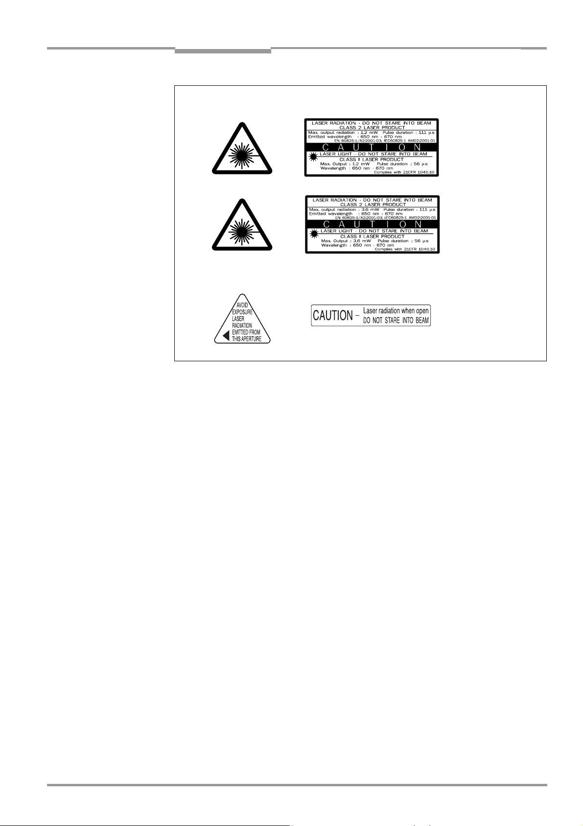
Fig. 2-1: Laser warning labels found on the CLV ......................................................................2-3
Fig. 3-1: CLV42x line/raster scanner with/without 105° angle attachment..................3-5
Fig. 3-2: Block diagram: CLV functions.........................................................................................3-6
Fig. 3-3: LED indicators ...................................................................................................................... 3-7
Fig. 4-1: Example line scanner: replacing the laser warning label .....................................4-2
Fig. 4-2: Location of the securing threads on the CLV...........................................................4-3
Fig. 4-3: Installation example: mounting the CLV with mounting bracket
no. 2 020 077.....................................................................................................................4-3
Fig. 4-4: Scanning methods: alignment with bar code and conveyor direction............4-4
Fig. 4-5: Definition of the reading distance a and the aperture angle a..........................4-4
Fig. 4-6: Line scanner: reading angles between the scan line and the bar code........4-5
Fig. 4-7: Preventing surface reflection: angle between the emitted light
and bar code (tilted away from the vertical axis) ...................................................4-5
Fig. 4-8: Count direction of the code position CP within the scan line.............................4-6
Fig. 4-9: Line scanner: appearance of the scan line in the "adjusting
mode" operating mode ....................................................................................................4-8
Fig. 4-10: Line scanner: installation example for the external reading pulse sensor ...4-9
Fig. 4-11: Line scanner: installation location of the polling reflector ................................ 4-11
Fig. 5-1: Block diagram: connection of the CLV to the CDB 420 or
CDM 420 connection module .......................................................................................5-1
Fig. 5-2: Connections of the host interface ................................................................................5-5
Fig. 5-3: Connections of the terminal interface.........................................................................5-7
Fig. 5-4: Connections of the "Sensor 1" switching input.......................................................5-8
Fig. 5-5: Connections of the "Sensor 2" switching input.......................................................5-9
Fig. 5-6: Connections of the "Result 1" switching output ..................................................5-10
Fig. 6-1: Bar code pattern (code 39; module width 0.35 mm (13.8 mil);
print ratio 2:1) ......................................................................................................................6-3
Fig. 6-2: CLV Setup: AutoSetup displayed in the terminal emulator..............................6-12
Fig. 6-3: CLV Setup: output of the reading result of the terminal
interface in terminal emulator ..................................................................................... 6-15
Fig. 6-4: Reading result of the terminal interface: structure for "good read".............6-16
Fig. 6-5: Reading result of the terminal interface: structure for "no read" ..................6-16
Fig. 6-6: CLV Setup: display of the percentage evaluation in the
terminal emulator.............................................................................................................6-18
Fig. 6-7: Appearance of scan line in the "Show CP-limits" mode ...................................6-19
Fig. 6-8: CLV Setup: "Operating Data" dialog box.................................................................6-20
Fig. 6-9: CLV Setup: output of the reading result of the host interface
in the terminal emulator at the beginning (in this case: O = Output)...........6-22
Fig. 6-10: CLV Setup: displaying the self-test result in the terminal emulator..............6-23
Fig. 6-11: CLV Setup: dialog box for AutoSetup execution ..................................................6-24
Fig. 7-1: Cleaning the reading window..........................................................................................7-1
Fig. 7-2: Cleaning the external optical sensor (reading pulse generator).......................7-2
Fig. 9-1: Dimensions of the CLV 42x line/raster scanner.....................................................9-3
Fig. 10-1: CLV 420-0010/-1010: reading range (DOF) for line/raster scanner.........10-2
Fig. 10-2: CLV 420-2010/3010: reading range (DOF) for line/raster
scanner with 105° angle attachment ......................................................................10-3
Fig. 10-3: CLV 421-0010/1010: reading range (DOF) for line/raster scanner ..........10-4
Fig. 10-4: CLV 422-0010/-1010: reading range (DOF) for line/raster scanner.........10-5
Fig. 10-5: CLV 42x: scanning frequency characteristic as a function of
the reading distance and resolution.........................................................................10-6
Fig. 10-6: CLV Setup: results of the AutoBaud detect function.......................................10-11
Fig. 10-7: User interface of the "CLV Setup" software .......................................................10-12
Fig. 10-8: CLV Setup: entering commands in the terminal emulator............................10-23
Fig. 10-9: Line scanner: calculating the number of scans for ladder-type
bar code arrangements..............................................................................................10-24
8 009 981/O078/16-08-2004 © SICK AG · Division Auto Ident · Germany · All rights reserved I-11
Page 12

Figures and Tables
Fig. 10-10: Line scanner: calculating the number of scans for fence-type
bar code arrangements ..............................................................................................10-24
Fig. 10-11: "Sensor 2" configuration for triggering the teach-in match code 1...........10-26
Fig. 10-12: Auxiliary input via the terminal interface of the CLV .........................................10-32
Fig. 10-13: CLV Setup: auxiliary input via the terminal emulator........................................10-33
Fig. 10-14: Dimensions of the mounting bracket no. 2 020 077.....................................10-40
Fig. 10-15: Dimensions of the mounting bracket no. 2 020 078.....................................10-40
Fig. 10-16: Copy of the Declaration of Conformity, Page 1 (scaled down)....................10-48
Fig. 10-17: Scannable bar codes with various module widths (print ratio 2:1) ...........10-53
Operating Instructions
CLV 42x bar code scanner
I-12 © SICK AG · Division Auto Ident · Germany · All rights reserved 8 009 981/O078/16-08-2004
Page 13

Operating Instructions Chapter 1
CLV 42x bar code scanner
Notes on this document
1 Notes on this document
1.1 Function
This document contains instructions for operating the following bar code scanners:
• CLV 420 standard range, with fixed focus
• CLV 421 long range, with fixed focus
• CLV 422 high density, with fixed focus
in the variants
• Line scanner without/with 105° angle attachment
• Raster scanner without/with 105° angle attachment.
This document provides information on
• Installation and electrical connection
• Startup
• Operation and configuration (parameterizing)
• Maintenance
• Replacing the device while retaining the parameter set
• Special applications and procedures.
The bar code scanners will all simply be called "CLV" below, except in such text passages
where a differentiation is required.
1.2 Target audience
This document is intended for persons who are responsible for the following activities:
1.2.1 Installation, electrical connection, maintenance and replacement
Electricians and service technicians
1.2.2 Startup, operation and configuration
Technicians and engineers
1.3 Information content
This document contains all of the information required to install, make electrical connections
and start up the CLV with the factory default settings.
A series of step-by-step instructions is provided for each of these activities.
The CLV is configured for specific applications using the Windows-based "CLV Setup" and
"CLV Assistant". Further assistance is also available in the form of the online help system
"CLV Setup Help". The procedure for installing and operating the user interface of the
software is described in the Appendix.
For further information on the design of the bar code scanner or on bar code technology in
general, please contact the Auto Ident division at SICK AG.
Internet address: www.sick.com.
8 009 981/O078/16-08-2004 © SICK AG · Division Auto Ident · Germany · All rights reserved 1-1
Page 14
Chapter 1 Operating Instructions
Notes on this document
CLV 42x bar code scanner
1.4 Symbols used
Some of the information in this document is marked specially so that you can access it
quickly:
Warning
Warnings are provided to prevent injury to operating personnel or serious damage to the bar
code scanner.
Always read warnings carefully and observe them at all times.
Note Notes indicate special features or characteristics.
Explanation Explanations provide background information on technical correlations.
Recommendation Recommendations help you carry out certain procedures more effectively.
Tip Tips explain settings in the user interface of the CLV Setup program.
Default setting Marks a section containing the values of the factory default settings.
SCANNING FREQUENCY This font indicates a term in the user interface of the CLV Setup program.
Icons refer to buttons in the user interface of the CLV Setup program.
"Host receive fault" This font indicates messages output via the terminal interface of the CLV.
This symbol identifies sections that describe steps carried out with the user interface of the
CLV Setup program.
This symbol is used to mark sections that describe steps carried out with the profile
programming.
This symbol refers to additional technical documentation.
An action must be performed. This symbol identifies single-step instructions.
Instructions consisting of several steps are numbered consecutively.
Here you select a function of the user interface of CLV Setup.
1-2 © SICK AG · Division Auto Ident · Germany · All rights reserved 8 009 981/O078/16-08-2004
Page 15

Operating Instructions Chapter 2
CLV 42x bar code scanner
Safety information
2 Safety information
2.1 Authorized personnel
For the CLV to function correctly and safely, it must be installed and operated by sufficiently
qualified personnel.
The end user must be supplied with the operating instructions.
The end user must be provided with expert tuition and is advised to read the operating
instructions.
The following qualifications are required for the various tasks involved:
2.1.1 Installation and maintenance
• Practical basic technical training
• Knowledge of the standard guidelines relating to safety in the workplace
2.1.2 Electrical connection and replacement
• Practical training in electrical engineering
• Knowledge of the standard safety guidelines relating to electrical engineering
• Knowledge regarding the operation of the devices in the relevant application
(e.g. conveyor belt)
2.1.3 Startup, operation and configuration
• Knowledge regarding the operation of the devices in the relevant application
(e. g. conveyor belt)
• Knowledge of the software and hardware environment of the relevant application
(e. g. conveyor belt)
• Basic understanding of Windows 95TM/98TM, Windows NTTM, Windows 2000TM or
Windows XP
• Basic understanding of an HTML browser (e. g. Internet ExplorerTM)
• Basic understanding of data transfer methods
• Basic understanding of bar code technology
TM
2.2 Intended use
The CLV is designed to detect and decode bar codes automatically. It is installed in a reading
station and reads bar codes on objects positioned on a conveyor belt, for example.
The CLV transfers the data content of the decoded bar codes via its host interface to a host
for further processing.
Any warranty claims vis-à-vis SICK AG will be rendered invalid if the device is used for any
other purpose or if changes are made to the device, including any made during the
installation and electrical connection procedures.
Note Don’t open the device. The producer warranty will be forfeited if the device is opened.
8 009 981/O078/16-08-2004 © SICK AG · Division Auto Ident · Germany · All rights reserved 2-1
Page 16
Chapter 2 Operating Instructions
Safety information
CLV 42x bar code scanner
2.3 General safety instructions and protection measures
Carefully read the general safety instructions and observe them at all times. This also
applies to the warnings provided for the activities described in each chapter of this
document.
Risk of injury by electrical current
In the CDM 420 Connection Module, the optional CMP 400 Power Supply Module is
connected to a mains voltage of 100 to 250 V AC/50 to 60 Hz
When working with electrical equipment, always follow the relevant safety regulations.
Laser radiation can seriously damage your eyesight.
The CLV uses a class 2 red-light laser. Looking directly at the laser beam can seriously
damage the retina in your eyes.
The entire glass window acts as a laser outlet aperture.
Caution – use of controls or adjustments or performance of procedures other than those
specified herein may result in hazardous radiation exposure.
As with sunlight, never look directly into the laser beam.
Do not direct the laser beam at other persons.
Mount and align the CLV in such a way to prevent the laser beam reflecting off mirrored
surfaces.
Do not open the housing.
(Opening the housing does not deactivate the laser diode).
Observe the laser protection specifications (latest version).
.
Laser power
The laser operates at a wavelength of λ = 650 to 670 nm (visible red light). The power
output of the laser beam at the reading window is max. 3.6 mW (CLV 421). The emitted
beam is not dangerous to human skin.
The product is classified in laser class 2 (laser class II) in accordance with EN 60825-1, IEC
60825-1, and 21 CFR 1040.10 (for publication date, see the warning sign on the device).
Laser warnings
The laser warning labels (Fig. 2-1) are attached at the following positions on the CLV:
• The laser warning symbol and the laser warning in GB English/US English on line/raster
scanners are positioned beside the reading window on the wide side of the device
(
Fig. 3-1, Page 3-5). The additional laser warnings in English applicable to the USA are
positioned beside the reading window on the front side of the device and at the back
end on the wide side.
• The laser warning symbol and the laser warning in GB English/US English on line/raster
scanners with a 105° angle attachment are positioned beside the reading window on
the wide side (
the USA are positioned on the back side of the attachment of the device and at the
back end on the wide side.
Fig. 3-1, Page 3-5). The additional laser warnings in English applicable to
2-2 © SICK AG · Division Auto Ident · Germany · All rights reserved 8 009 981/O078/16-08-2004
Page 17
Operating Instructions Chapter 2
CLV 42x bar code scanner
Safety information
black-yellow signed on device:
CLV 420/422
CLV 421
black-silver signed on device:
Fig. 2-1: Laser warning labels found on the CLV
Note The device is supplied with an additional set of laser warning labels in German/US English
and in French/US English. If necessary, these can be used to cover the GB English/
US
English warning.
If the CLV is installed in a machine/panel with the result that the laser warning labels
are no longer visible, additional warnings (not included in the scope of delivery) must
be provided on the machine beside the emergence aperture of the laser beam.
Internal protective circuits
Explanation The CLV is equipped with monitoring circuit-breakers that switch off the laser diode if
problems arise with the laser beam.
No maintenance required to keep this product in
compliance with laser class II.
Activation and deactivation of the laser diode when reading is controlled by the reading
pulse (trigger source).
A timer (laser timeout) automatically deactivates the laser diode 10 minutes (default setting)
after a continuous reading pulse is initiated in reading mode with switching input pulse
modes "Sensor Input" and "Serial Interface". In this case, the CLV outputs the message:
"Laser safety timeout" via the terminal interface.
The reading pulse interval is to be terminated by resetting the pulse signal. The laser diode
is activated again by the next reading pulse.
The laser timeout can be set in the range of 1 min to 25 h or deactivated (see Table 6-4,
Page 6-8).
In the "Percentage Evaluation" mode, "Adjusting" mode, "Show CP-limits" and
"AutoSetup" mode as well as in the pulse modes "Free Running" and “Continuous
Read“, in reading mode, the laser diode is constantly activated. In the "reflector
polling" trigger mode the laser diode is switched on for each 20th
scan.
8 009 981/O078/16-08-2004 © SICK AG · Division Auto Ident · Germany · All rights reserved 2-3
Page 18

Chapter 2 Operating Instructions
Safety information
CLV 42x bar code scanner
2.4 Quick stop and quick restart
2.4.1 Switching off the CLV
Switch off the power supply or remove the CLV connector from the connection module.
This can result in loss of the following (at the most):
• the application-specific parameter set, if it was only stored temporarily in the CLV
• the last reading result
• daily operating data
(operating hours counter, trigger count, no. of good reads, no. of no reads, maximum
duration trigger, minimum duration trigger, matchcode 1, matchcode 2, no match)
2.4.2 Restarting the CLV
Switch on the supply voltage or reattach the connector to the connection module.
The CLV resumes operation with the parameter set that was last stored permanently
and resets the daily operating data.
2.5 Environmental information
The CLV is designed to cause minimum impact on the environment. It does not contain any
silicone-based materials on the hosuing surface and, therefore, does not represent any
problems for e.g. paint sprayers in paint shops.
2.5.1 Power requirements
The power requirements are particularly low:
• the CLV 420/421/422 line/raster scanners have a max. power consumption of 3.5 W
The value is given for devices with disconnected switching outputs.
2.5.2 Disposal after final decommissioning
Always dispose of unusable or irreparable devices in a manner that is not harmful to the
environment and in accordance with the applicable national waste disposal regulations. The
CLV can be separated into recyclable secondary raw materials and special-category waste
(electronic scrap). See
At present, SICK AG does not accept any unusable or irreparable devices.
Chapter 7.3 Disposal, Page 7-2.
2-4 © SICK AG · Division Auto Ident · Germany · All rights reserved 8 009 981/O078/16-08-2004
Page 19
Operating Instructions Chapter 3
CLV 42x bar code scanner
Product description
3 Product description
3.1 Design
3.1.1 Scope of delivery
In the packaging the CLV is supplied with the following:
• two polling reflectors for automatic reading pulse generation
• an information sheet (note on device) with terminal diagram and Quick Start instructions
• an additional set of Class 2 laser warning labels (self-adhesive) in German/US English
and French/US English
Depending on the number of devices ordered, one or more copies of the following:
• CD ROM (no. 2 029 112) with
TM
– "CLV-Setup" program for Windows
(HTML files)
– "CLV-Connect" PC software (HTML files showing terminal diagrams)
– CLV 42x Operating Instructions in English and German as PDF edition as well as
additional publications (connections module, other SICK bar code scanners)
– freely available "Acrobat Reader" PC software for reading PDF files
and the "CLV-Setup Help" online help system
Note The latest versions of all the current publications/programs on the CD ROM can also be
downloaded from
www.sick.com.
Depending on the number of copies ordered, the delivery includes (optional):
• CLV 42x Operating Instructions in English and/or German (printed edition)
Chapter 10.11 Accessories, Page 10-38 provides an overview of the available installation
accessories, connection modules, cables and plug-in connections and sensors for reading
pulse generation.
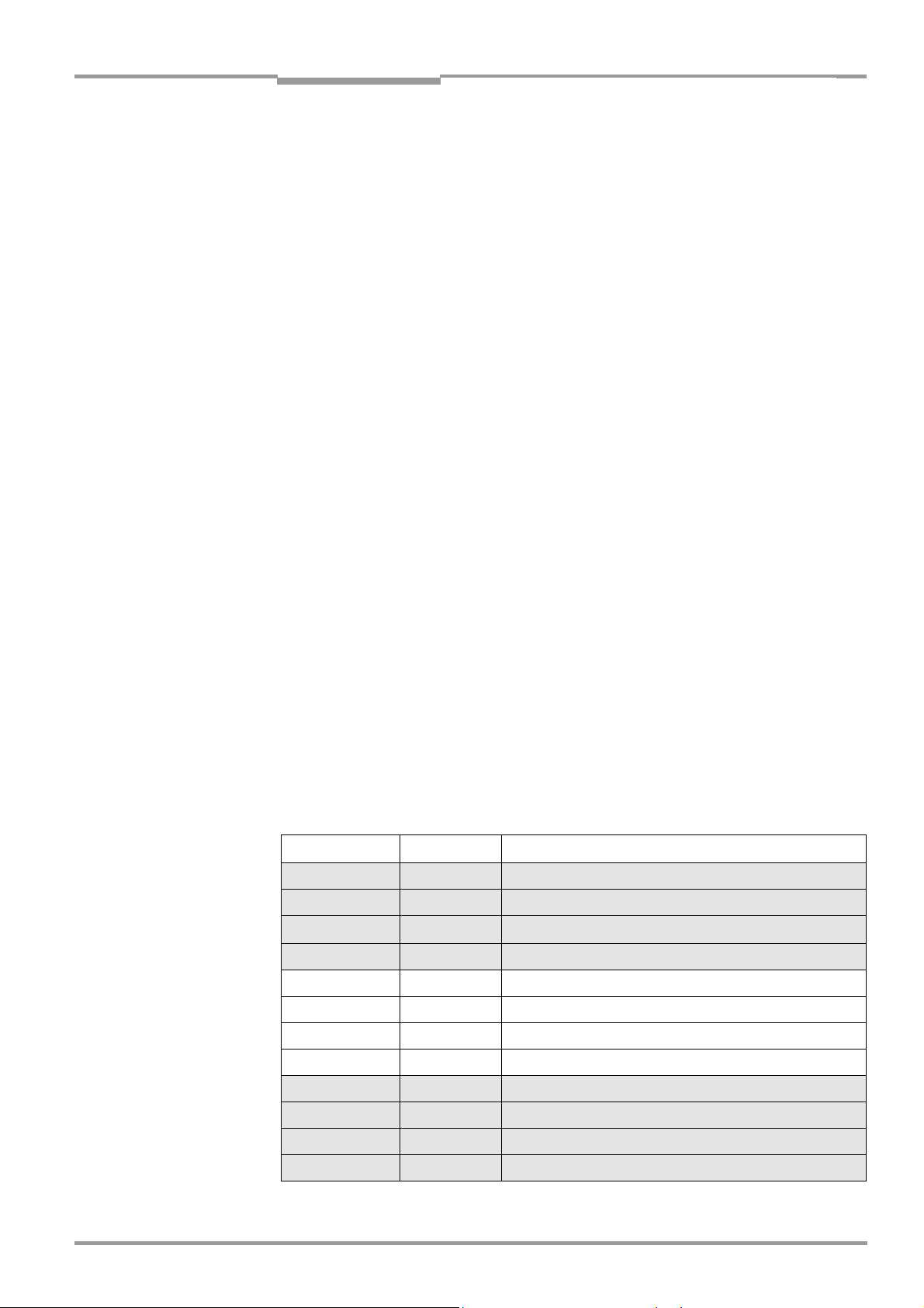
3.1.2 Variants
The CLV is available in the following variants:
Type Order no. Scan procedure
CLV 420-0010 1 022 031 Line scanner, standard range
CLV 420-1010 1 022 032 Raster scanner, standard range
CLV 420-2010 1 022 033
CLV 420-3010 1 022 034 Raster scanner with 105° angle attachment, standard range
CLV 421-0010 1 022 547 Line scanner, long range
CLV 421-1010 1 022 616 Raster scanner, long range
CLV 421-2010 1 022 617 Line scanner with 105° angle attachment, long range
CLV 421-3010 1 022 618 Raster scanner with 105° angle attachment, long range
Line scanner with 105° angle attachment, standard range
CLV 422-0010 1 022 548 Line scanner, high density
CLV 422-1010 1 022 619 Raster scanner, high density
CLV 422-2010 1 022 620 Line scanner with 105° angle attachment, high density
CLV 422-3010 1 022 621 Raster scanner with 105° angle attachment, high density
Table 3-1: Variants of the CLV 42x
8 009 981/O078/16-08-2004 © SICK AG · Division Auto Ident · Germany · All rights reserved 3-1
Page 20

Chapter 3 Operating Instructions
Product description
CLV 42x bar code scanner
3.1.3 System requirements
The following are required to start up and operate the CLV 42x:
1. A SICK connection module to provide the power supply and connect the data and
function interfaces.
Available types:
– CDB 420-001 (no. 1 023 885) for 10 to 30 V DC, enclosure rating max. IP 65
– CDM 420-0001 (no. 1 025 362) for 10 to 30 V DC, enclosure rating max. IP 65
– or –
Alternatively, a non-SICK power supply unit with a voltage output of 10 to 30 V DC
(functional extra-low voltage pursuant to IEC
364-4-41) and at least 4 W power output.
Cable no. 6 010 137 with 15-pin D Sub HD connector and one open end for connecting
the CLV to the external power pack.
Note The CLV 42x is UL certificated when a class 2 power supply according to UL 1310 is
used.
2. The following operating voltages/power outputs
– CDB 420-001: 10 to 30 V DC, pursuant to IEC 364-4-41, at least 4 W
– CDM 420-0001: 10 to 30 V DC, pursuant to IEC 364-4-41, at least 4 W
– If the following modules are additionally built-in in the CDB 420 module:
CMC 400 Connection Module Cloning: 10 to 30 V DC, additionally 0.5 W
– If the following modules are additionally built-in in the CDM 420 module:
CMC 400 Connection Module Cloning: 10 to 30 V DC, additionally 0.5 W
CMD 400 Connection Module Display: 18 to 30 V DC, additionally 1 W
CMF 400 Connection Module Fieldbus: 18 to 30 V DC, additionally 2 W
3. With external clock pulse (start/stop of reading interval) supply via the “Sensor 1“
switching input: a suitable reading pulse sensor for signaling the presence of an object
with a bar code, e. g. a photoelectric reflex switch.
4. With optional external clock pulse (stop of reading interval) supply via the “Sensor 2“
switching input: a suitable reading pulse sensor for signaling the end of reading intervall,
e.g. a photoelectric reflex switch.
5. To separate bar codes with the same name (same code type, identical data content)
using the "Compare Code Position" function: a suitable incremental encoder.
6. A higher-level computer (host) with a data interface of type RS 422/485 or RS 232.
7. A PC (at least 80486, 66 MHz, 16 MB RAM, CD-ROM drive, serial interface, mouse
(recommended) with Windows 95
Windows XP
TM
.
TM
/98TM, Windows NTTM, Windows 2000TM or
8. A 3-core RS 232 data cable (null modem cable) with two 9-pin D Sub sockets for
connecting the PC to the terminal interface of the CLV in the connection module CDB
420 or CDM 420, e. g. no.
2 014 054. Pin 2 (RxD) and Pin 3 (TxD) are crossed.
9. To use the online help system CLV Setup Help, an HTML browser is required, e. g.
Internet Explorer
TM
.
10. To connect the CLV to Profibus DP, DeviceNet, and Ethernet: the corresponding
CMF 400 Connection Module Fieldbus (Operating instructions see Chapter 10.13
Supplementary documentation, Page 10-41).
11. For connection of the CLV to the CAN bus: the operating instructions "Application of the
the CAN interface" (no. 8 009 180, English)
3-2 © SICK AG · Division Auto Ident · Germany · All rights reserved 8 009 981/O078/16-08-2004
Page 21

Operating Instructions Chapter 3
CLV 42x bar code scanner
Product description
3.1.4 Product features and functions (overview)
High-performance laser scanner:
• Fixed focus
• Line scanner, variant: raster scanner
• Front reading window, variant: side reading window
• Reading range 60 to 740 mm (2.36 to 29.1 in), type dependent
• Resolution 0.15 to 1.0 mm (5.9 to 39.4 mil), type dependent
• Scanning/decoding frequency 400 to 1200 Hz
• Function to adjust on the code print quality, also via reading configuration
• Variable active evaluation range of the scan line
Safety and user-friendly features:
• Robust, compact metal housing, max. IP 65, CE certification
• UL certificated when a class 2 power supply according to UL 1310 is used
(valid only with corresponding product marking on the nameplate).
• Laser class 2, laser diode switches off if reading interval is active for too long and if the
output power is exceeded
• Automatic self-test on startup. Can also be triggered at any time
• Diagnosis tools for installing and monitoring the system
• Parameterized output of reading diagnosis data in the read result
• Operating data query, and error messages
• Test string function for signaling readiness for operation
• Future proof thanks to firmware update via serial data interface (flash PROM)
• Low power consumption, other voltage range
Easy operation/configuration:
• With "CLV-Setup" PC software for Windows (online), integrated Assistant and Help
system
• With Profile bar codes (offline)
• Alternatively with simple command strings, also for use with special devices
• Four status LEDs
• Beeper to confirm device functions or operating steps (can be switches off)
Operating modes:
• Reading mode
• Percentage evaluation - for assessing the quality of the reads
• AutoSetup
• Special functions for system installation
8 009 981/O078/16-08-2004 © SICK AG · Division Auto Ident · Germany · All rights reserved 3-3
Page 22

Chapter 3 Operating Instructions
Product description
CLV 42x bar code scanner
Bar code evaluation:
• All standard bar code types
• Max. 10 codes per reading pulse (max. 100 characters), max. 3 per scan
• Separation of identical bar codes of the same code type
• Code comparison (max. 2 matchcodes), can also be used as filter for the reading result
• Sort sequences: code position, FIFO, LIFO, code length list
• Manipulation of the data output string via filter or format mask
Reading pulse:
• External reading pulse, via switching input or serial interface
• Free running with timeout
• Continuous Read
• Reflector Polling for generating the reading gate automatically
Electrical interfaces:
• Serial host interface (RS 232, RS 422/485) with variable transfer rate, protocol and
telegram structure
• Serial terminal interface (RS 232) as auxiliary data interface with special diagnosis
functions
• CAN interface for integration in the SICK CAN scanner network or a CANopen network
• 2 switching inputs for external reading pulse and special function (e.g. teach-in of match
code)
• 2 switching outputs for signaling defined events in reading mode
Connections:
• All interfaces are connected via a cable with one 15-pin D Sub HD plug
• CDB 420 or CDM 420 Connection Module for connection to host (stand-alone) and for
integration in SICK CAN scanner network
• CMF 400 Connection Module Fieldbus in the CDM 420 Connection Module for
connection to field bus systems
3-4 © SICK AG · Division Auto Ident · Germany · All rights reserved 8 009 981/O078/16-08-2004
Page 23
Operating Instructions Chapter 3
CLV 42x bar code scanner
Product description
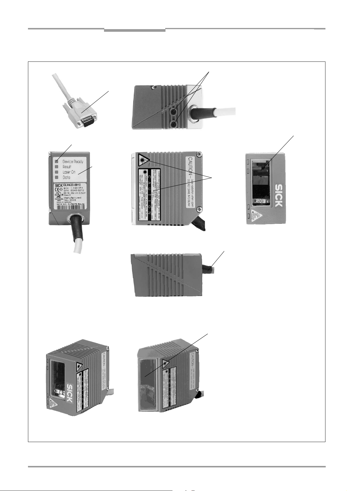
3.1.5 View of line/raster scanner devices
2
1
3
7
6
4
Front reading window
Side reading window
8
5
Legend:
1 D Sub HD plug, 15-pin
2 Tapped blind holes M4,
6 mm (0.24 in) deep
3 Reading window
4 Laser warning labels
5 Connection cable
6 Sound opening of the beeper
(hidden)
7 LEDs (status indicators)
8 integrated angle attachment,
with 105° light reflection
Fig. 3-1: CLV42x line/raster scanner with/without 105° angle attachment
8 009 981/O078/16-08-2004 © SICK AG · Division Auto Ident · Germany · All rights reserved 3-5
Page 24
Chapter 3 Operating Instructions
Product description
CLV 42x bar code scanner
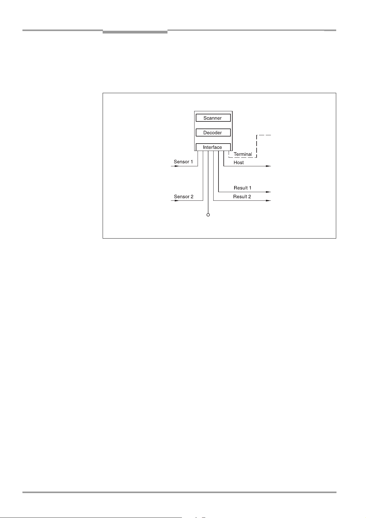
3.2 Method of operation
The CLV first scans the bar code with a scan line and then decodes it. The CLV forwards the
data via the serial host interface (main data interface) to a host/PC for further processing.
An overview of the CLV functions is provided in
CLV 42x
Fig. 3-2.
PC
Operation
Parameterizing, etc.
Photoelectric switch
Reading pulse
Signal
Teach-in match code 1
Path increment
End of reading interval
DC 10 to 30 V
Fig. 3-2: Block diagram: CLV functions
HOST
Further processing
of the reading result
Status indicator
e. g. Good Read
e. g. No Read
The tried and tested standard decoder of the CLV series is available for decoding.
The CLV derives useful diagnosis data from the reading process and transfers it to the host.
It also records operating data that can be interrogated at any time. The quality of the read
can be checked in "Percentage Evaluation" mode.
To start a reading process when an object is located in the reading field, the CLV requires a
suitable trigger. This opens a time window ("reading interval") in the CLV for the reading
procedure. In the default setting, this trigger is supplied by an external reading pulse sensor.
Alternative trigger sources include reflector polling, free-running mode or a command via the
host interface.
The current operating status is indicated by four LEDs.
A beeper indicates the status of the reading result. In the default setting, the "Good Read"
function is selected for this.
If the trigger is supplied externally by a sensor, the "Sensor 1" switching input signals the
start of the reading procedure to the CLV. The "Sensor 2" switching input can be used to
teach in a match code. The "Result 1" and "Result 2" switching outputs can be assigned
various functions and trigger external devices, such as a PLC.
The CLV is operated and configured via the serial terminal interface (auxiliary interface) using
the "CLV Setup" software or via the host/terminal interface and command strings.
System messages, warnings and error messages help you with configuration and with
locating the source of errors during startup and in reading mode.
3-6 © SICK AG · Division Auto Ident · Germany · All rights reserved 8 009 981/O078/16-08-2004
Page 25

Operating Instructions Chapter 3
CLV 42x bar code scanner
Product description
3.2.1 Scan procedure variants
Line scanner
Generates a scan line. Due to the V-principle of beam deflection, the reading field height (for
evaluating the useful length of the scan line) is dependent on the reading distance.
Raster scanner
Generates 8 parallel scan lines that are offset by the same distance. Due to the V-principle
of beam deflection, the reading field height (for evaluating the useful length of the scan lines)
is dependent on the reading distance.
Raster height of the scan line field: 15 mm (0.59 in) at a reading distance of 200 mm
(7.88 in) (front reading window).
3.3 Indicators and operating elements
3.3.1 Operating elements
The CLV is operated and configured via the terminal interface (auxiliary interface) using the
"CLV Setup" program or using command strings sent via the host interface/terminal
interface. A variety of parameterizing options allow you to adapt the device to a wide range
of applications.
The following can be defined (among others):
• the configuration of the code types to be read
• the reading, evaluation and output characteristics
• the communication parameters of the host interface
• the structure of the data output string for "good read" and "no read" on the host
interface
• the function of the terminal interface
Chapter 10.4 Installation and operating instructions for the PC-based "CLV Setup" program,
Page 10-7 describes the procedure for installing the "CLV Setup" program and how to
operate the user interface. Configuration (parameterizing) is explained in Chapter 6.4
Configuration (parameterizing), Page 6-4.
3.3.2 Function of the LED indicators
Four LEDs indicate the operating status, activity of the laser diode, output of the reading
result, and data transfer on the host interface. The LED indicators (
the rear of the device. Table 3-2 shows the meaning of the LED indicators in the different
operating modes/functions.
Fig. 3-3: LED indicators
8 009 981/O078/16-08-2004 © SICK AG · Division Auto Ident · Germany · All rights reserved 3-7
Fig. 3-3) are located on
Page 26
Chapter 3 Operating Instructions
Product description
CLV 42x bar code scanner
Operating mode LED Indication Function
Start Device Ready
orange • lights up after power-up if the self-test was successful and the wait time
for reading the profile bar codes has expired
Laser On
Reading mode Device Ready
orange • lights up while the laser diode for reading the profile bar codes is active
orange • illuminates constantly
• extinguishes with new operating mode/function
Laser On
orange • lights up if reading diode active
(The laser diode is activated/deactivated by reading pulse)
• lights up constantly in the pulse modes "free running" and “Continuous
, as the laser diode is always active
Read“
• lights up with every 20th scan in the "reflector polling" pulse mode.
The scan line is faintly visible.
Result
orange LED is connected to the "Result 2" switching output. It indicates the
selected result status for the set pulse duration of the output.
• lights up after a good read
(default setting: "good read")
• lights up (match code comparison active) if the read bar code matches
the predefined match code(s) and the corresponding result status output
is selected for the "Result 2" output
orange • flickers while the CLV transfers data to the host on the host interface
orange • lights up constantly (Free Running mode)
orange Behavior depends on the reading quality:
Percentage
evaluation
Data
Laser On
Result
• extinguishes if reading rate < 30 %
• blinks twice a second if reading rate 30 % to 70 %
• blinks five times a second if reading rate 70 % to 90 %
• lights up constantly if reading rate > 90 %
Profile
Laser On
orange • lights up while the profile bar codes are being read (Free Running mode)
programming
AutoSetup Laser On
orange • lights up while the application-specific bar codes are being read (Free
Running mode)
Adjusting mode Laser On
Show CP-limits Laser On
orange • lights up constantly (Free Running mode)
orange • blinks bright/dark alternately, in the frequency with which the scan line is
partially masked out
Table 3-2: Meaning of the LED indicators
3-8 © SICK AG · Division Auto Ident · Germany · All rights reserved 8 009 981/O078/16-08-2004
Page 27

Operating Instructions Chapter 3
CLV 42x bar code scanner
Product description
3.3.3 Function of the beeper
The beeper uses different tone sequences and lengths (Table 3-3) to signal whether
functions have been executed successfully and whether any malfunctions have occurred.
For information on troubleshooting, see Chapter 8.5 Troubleshooting, Page 8-5.
In the default setting, the beeper indicates the event status "Good Read" by means of a
"Low" (quiet) beep. It is assumed in these operating instructions, that the beeper is
operated with the default setting in Reading mode.
The sound opening of the beeper is located on the rear, narrow side of the device and below
the LED labeling.
Operating mode Tone sequence Beeper function
Start Beep • signals that the self-test after power-up was successful
Reading mode Beep Beep • confirms that the device has assumed Reading mode after power up
and after the wait time of 5 s for reading the profile bar codes has
elapsed
Beep • confirms a successful read (good read; default setting) and the reading
result output
Profile programming
Start AutoSetup
Profile programming Beep • confirms successful read of profile bar code
Exceeding the laser timeout Beep Beep Beep • signals that the laser diode has been deactivated after the laser timeout
Table 3-3: Beeper function
Tip
Beep • confirms successful read of profile bar code for start/end of AutoSetup
Beep Beep • confirms successful read of application-specific bar code and start of
reading mode
Beep (long tone) • signals that the application-specific bar code was not read
Beep Beep • confirms start of reading mode 10 s after last profile bar code was read
of 10 min (default setting) was exceeded in Reading mode. The reading
pulse is still active.
The behavior of the beeper in reading mode can be changed on the DEVICE CONFIGURATION
tab in the CLV Setup program.
Volume:
Click the required field in the BEEPER VOLUME section.
Output function for the result status
1. Click the RESULT OUTPUT PARAMETERS button in the RESULT OUTPUT section.
The RESULT OUTPUT PARAMETERS dialog box is displayed.
2. Click the BEEPER list field in the RESULT FUNCTIONS section.
The list containing the available result status functions appears.
3. Click the required function and confirm with "OK".
4. Perform a download to the CLV. This is done by clicking in the toolbar.
The DOWNLOAD PARAMETER dialog box is displayed.
5. Confirm the dialog box by selecting the PERMANENT save option.
The CLV operates the beeper with the values selected for the result status indication and
volume.
8 009 981/O078/16-08-2004 © SICK AG · Division Auto Ident · Germany · All rights reserved 3-9
Page 28

Chapter 3 Operating Instructions
Notes
Product description
CLV 42x bar code scanner
3-10 © SICK AG · Division Auto Ident · Germany · All rights reserved 8 009 981/O078/16-08-2004
Page 29

Operating Instructions Chapter 4
CLV 42x bar code scanner
Installation
4 Installation
4.1 Overview of installation sequence
• Change the language version of the laser warning label (if necessary)
• Select the installation location for the CLV
• Align the CLV with the bar code
• Install the CLV
• Install the CDB 420 or CDM 420 connection module
• Connect the CLV to the CDB 420 or CDM 420 connection module
• Adjust the CLV
• Install the reading pulse sensor for triggering the reading pulse
• Alternative: Attach a polling reflector for internal reading pulse triggering
Note Don’t open the device. The producer warranty will be forfeited if the device is opened.
4.2 Installation preparations
4.2.1 Laying out required components to be installed
• CLV bar code scanner
4.2.2 Laying out accessories
• Small mounting bracket no. 2 020 077 or large mounting bracket no. 2 020 078 with
2 x M4 x 8 mm (0.32 in) screws for installing the bracket to the CLV (not included with
the CLV)
– or –
Alternatively, if the bracket is supplied by the user:
– Stable installation device that allows the alignment of the CLV to be varied in the x
and y axes. The maximum weight of the CLV (line/raster scanner) is 250 g (8.8 oz),
or approx. 320 g (11.3 oz) with additional attachment (with cable).
– Two M4 screws for the CLV. The screw length depends on the wall thickness of the
bracket used. Depth of engagement in CLV
surface.
• CDB 420 or CDM 420 connection module (not included with CLV)
• Reading pulse sensor for external reading pulse trigger, e. g. photoelectric reflex
switch/photoelectric proximity switch (not included with the CLV)
– or –
Polling reflectors for automatic internal generation of the reading pulse trigger
max. 6 mm (0.24 in) from housing
4.2.3 Laying out other required materials
• Two M4 screws for securing the SICK mounting bracket to the base. The screw length
depends on the wall thickness of the base.
• Set of laser warning labels (if necessary)
• Tools
• Measuring tape (up to 1 m (39.4 in))
• Protractor
8 009 981/O078/16-08-2004 © SICK AG · Division Auto Ident · Germany · All rights reserved 4-1
Page 30

Chapter 4 Operating Instructions
Installation
CLV 42x bar code scanner
4.2.4 Replacing the laser warning label
If necessary, replace the laser warning label in GB English/US English on the CLV with the
required language (
Fig. 4-1).
The device is delivered with a set of laser warnings in:
• German/US English
• French/US English
See also Chapter 2.3 General safety instructions and protection measures, Page 2-2.
Included label set:
(set for CLV 421 pictured here)
Fig. 4-1: Example line scanner: replacing the laser warning label
4.2.5 Selecting the installation location
When you select the installation location, the distance between the CLV and the host and
between the CLV and the bar code are important.
Distance between the CLV and the host
The CLV can be installed without a connection to the SICK CAN Scanner Network or to a bus
connection max.
1,200 m (3,936.96 ft) away from the host. The distance which can be
achieved depends on the selected model of the host interface and the set data transfer
rate, however. See
Table 5-2, Page 5-3.
Distance between the CLV and the CDB 420 or CDM 420 connection module
The CDB 420 or CDM 420 connection module must not be located further than 10 m
(32.8 ft) away from the CLV, since the "CLV Setup" program on the PC accesses the
terminal interface of the CLV via this module (RS 232).
4.2.6 Mounting accessories
The CLV is mounted with the help of two tapped blind holes (M4) located on the bottom
narrow side of the device.
Fig. 4-2 shows the position of the threaded hole for both housing
models. The complete dimensions of the CLV housing are shown in Fig. 9-1, Page 9-3.
4-2 © SICK AG · Division Auto Ident · Germany · All rights reserved 8 009 981/O078/16-08-2004
Page 31

Operating Instructions Chapter 4
p
)
CLV 42x bar code scanner
Installation
10
(.39)
(1.39)
32.8
(1.29)
59
(2.32)
Fig. 4-2: Location of the securing threads on the CLV
M4, 6 (.24) deep
4
(.15)
The CLV can be installed using the following SICK brackets:
• Small mounting bracket, no. 2 020 077
• Large mounting bracket, no. 2 020 078
The brackets are designed to support a variety of installation positions and alignments of
the CLV in two planes.
The slots in the brackets allow a turning freedom of ±15° for the fine adjustment of the CLV.
35.2
45.8
(1.80)
72
(2.84)
Fig. 4-3 shows a mounting example.
10
(.39)
35.2
(1.39
4
(.15)
M4, 6 (.24) dee
All dimensions in mm (in)
Fig. 4-3: Installation example: mounting the CLV with mounting bracket no. 2 020 077
8 009 981/O078/16-08-2004 © SICK AG · Division Auto Ident · Germany · All rights reserved 4-3
Page 32

Chapter 4 Operating Instructions
Installation
CLV 42x bar code scanner
4.2.7 Distance between the CLV and the bar code
Basic alignment of the scan line to the bar code
Depending on the application, the line scanner or raster scanner version of the CLV is used.
Fig. 4-4 shows how the device is aligned with the bar code on the object for each of the two
scanning methods.
Raster scannerLine scanner
Fig. 4-4: Scanning methods: alignment with bar code and conveyor direction
Reading distance between bar code and aperture angle α
The distance between the reading window of the CLV and the bar code must not exceed
the technical limits. The height of the reading field is shown as a function of the reading
distance “a“ for various resolutions (module widths) in
Chapter 10.2 Specification diagrams,
Page 10-1.
Fig. 4-5 shows the definition of the reading distance a from the reading window and of the
aperture angle α for each of the two scanning methods.
Line scanner Raster scanner
Reading distance a
Reading distance a
Fig. 4-5: Definition of the reading distance a and the aperture angle α
The useable aperture angle α is max. 50° for both scanning methods, even with the
additional 105
° angle attachment. Due to the V-principle of beam deflection, the reading
field height (for evaluating the useful length of the scan line) depends on the reading
distance.
4-4 © SICK AG · Division Auto Ident · Germany · All rights reserved 8 009 981/O078/16-08-2004
Page 33

Operating Instructions Chapter 4
CLV 42x bar code scanner
Installation
Angular alignment of the CLV
Optimum alignment of the CLV is achieved when the scan line travels over the bar code lines
almost at a right angle (90
°) (Fig. 4-4). All possible reading angles that can occur between
the scan line and the bar code must be taken into consideration (Fig. 4-6 and Table 4-1).
β
α
Reading
area
α: Azimuth angle (tilt)
β: Inclination angle (pitch)
γ: Rotation angle (skew)
γ
Reading
distance
Fig. 4-6: Line scanner: reading angles between the scan line and the bar code
Angle Limit
Azimuth α (tilt) max. 30° (resolution 0.35 mm (13.8 mil), depending on the code print)
Inclination β (pitch) max. 45° (depending on the module width)
Skew γ max. 45° (depending on the module width)
Table 4-1: Permissible reading angles between the scan line and bar code
Preventing surface reflection
If the light from the scan line strikes the surface of the bar code perpendicularly, interference
may be caused by reflections when the returned light is received. To prevent this effect, the
CLV must be installed in such a way that the emitted light is tilted slightly with respect to the
vertical axis.
Fig. 4-7 shows an example of this using the line scanner.
Line scanner
(front reading window)
105°
top view top view
Fig. 4-7: Preventing surface reflection: angle between the emitted light and bar code (tilted away
from the vertical axis)
Line scanner with
105
° angle attachment
(side reading window)
105°
The laser beam from the line/raster scanner with angle attachment is emitted at an angle
of 105
° with respect to the housing. Depending on the application, the device can also be
installed flush with the conveyor belt.
8 009 981/O078/16-08-2004 © SICK AG · Division Auto Ident · Germany · All rights reserved 4-5
Page 34
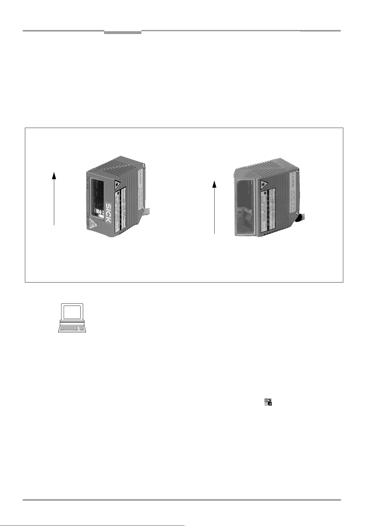
Chapter 4 Operating Instructions
Installation
CLV 42x bar code scanner
4.2.8 Count direction of the code position CP
Explanation The CLV can scan and decode several bar codes with each read.
In doing so, it determines the specific local reading diagnosis data for each bar code, i.e. the
position (CP value) of the center of the bar code within the scan line.
Fig. 4-4 shows the count direction of the code position.
By determining the CP value, the device can separate identical bar codes (code type, code
length, and data content) and assign the bar code data in the reading result to its position
on the object.
Line/raster scanner
100
CP
0
Front reading window
Deflection angle α (aperture angle) in scan direction: 1° = 2 CP (50° = 100 CP)
Fig. 4-8: Count direction of the code position CP within the scan line
Tip
In the default setting, the CLV does not output the value "CP" in the reading result of the
host interface. If this is required to evaluate the result in the host, the values can be included
in the Code-Info/Separator block of the output string using the CLV Setup program.
Line/raster scanner
with angle attachment
100
CP
0
Side reading window
Configuring the Code-Info/Separator
1. Select the DATA STRINGS tab.
2. Click the CODE-INFO/SEPARATOR field.
The dialog window EDIT PARAMETER: TFS dialog box is displayed.
3. In the drop-down list, click the CP parameter.
CP then appears on the top line.
4. Confirm the dialog box with "OK".
5. Perform a download to the CLV. This is done by clicking in the toolbar.
The DOWNLOAD PARAMETER dialog box is displayed.
6. Confirm the dialog box by selecting the PERMANENT save option.
The CLV outputs the CP value for each bar code in the reading result via the host
interface. The values are displayed as a 3-digit number in the associated “CodeInfo/Separator“ block.
4-6 © SICK AG · Division Auto Ident · Germany · All rights reserved 8 009 981/O078/16-08-2004
Page 35
Operating Instructions Chapter 4
CLV 42x bar code scanner
Installation
4.3 Installing and adjusting the device
4.3.1 Installing the CLV
1. Prepare the base for installing the bracket as described in Chapter 4.2.2 Laying out
accessories, Page 4-1.
2. Place the object containing the bar code within the visible range of the CLV (in the
position at which it is to be read) with the conveyor belt switched off.
3. Align the CLV with the bar code (in accordance with the scanning method) in such a way
that
– with the line/raster scanner, the narrow end with the LED indicators is almost parallel
with the bar code surface
– with the line/raster scanner with angle attachment, the wide side with the laser
warning labels is almost parallel with the bar code surface
All of the possible reading angles must be taken into consideration. See Fig. 4-6,
Page 4-5.
4. If relevant to the evaluation, pay attention to the count direction of the code position if
applicable. See
5. Install the CLV bracket on the base.
Fig. 4-8, Page 4-6.
Risk of damage to the device
The maximum depth of engagement of the two tapped blind holes M4 is 6 mm (0.24 in).
Longer screws will damage the device.
Use screws with the correct length.
6. Screw the M4 screws through the bracket into the tapped blind holes of the CLV.
7. Tighten the screws slightly.
8. Adjust the CLV as described below.
4.3.2 Adjusting the CLV
The "percentage evaluation" mode supports the adjustment of the CLV. In this mode, the
CLV displays the quality of the bar code reads that enter the CLV reading field statically (the
object is not moved on the conveyor belt). The CLV performs 100 scans in Free Running
mode and evaluates the reading quality statistically. It outputs the reading result
continuously every 2 s via the terminal interface.
The behavior of the "Result" LED also indicates the reading quality:
• If the LED does not light up, the CLV cannot read the bar code
(reading quality < 30 %).
• If the LED blinks, the CLV is having problems reading the bar code
(reading quality 30 % to 90 %).
• When the LED lights up constantly, the CLV is aligned optimally
(reading quality > 90 %). The scanning frequency in the default setting is 700 Hz.
1. Connect the CLV to the CDB 420 or CDM 420 connection module and switch on the
power supply to the module (see
Page 5-5).
Once the CLV has started, it outputs a tone to indicate that the self-test was
successfully completed. Shortly afterwards, it outputs two tones to indicate that it has
assumed Reading mode. The "Device Ready" LED lights up.
8 009 981/O078/16-08-2004 © SICK AG · Division Auto Ident · Germany · All rights reserved 4-7
Chapter 5.5.3 Connecting the power supply,
Page 36

Chapter 4 Operating Instructions
Installation
CLV 42x bar code scanner
2. Connect the PC to the terminal interface of the CLV. For this purpose, connect a 3-core
RS
232 data cable to the internal 9-pin "Aux" plug of the module (see Chapter 5.5.6
Connecting the PC, Page 5-7).
3. Start Windows and "CLV Setup" on your PC (see Chapter 10.4.3 Starting "CLV Setup",
Page 10-10).
Activating “Percentage Evaluation“ mode
4. From the VIEW menu, choose PERCENTAGE EVALUATION.
5. The dialog window for choosing the distance configuration is then displayed.
6. Confirm the dialog window with "OK".
The Terminal Emulator is launched and displays the reading result continuously (see
Chapter 6.5.2 Percentage evaluation, Page 6-17).
Monitor the reading quality (%) during each of the subsequent steps!
Performing fine adjustment
7. Align the CLV in such a way that the angle between the scan line and the bars on the
bar code CLV is almost 90
°.
8. To prevent interfering reflections, tilt the CLV away from the vertical axis so that the light
strikes the bar code at an angle of approx. 105
° (line scanner) (Fig. 4-7, Page 4-5).
9. If necessary, position the center of the scan line exactly on the bar code (see
Chapter 4.3.3 Auxiliary functions for adjustment, Page 4-8).
10. Move objects carrying bar codes into the CLV reading field manually under realistic
conditions and check the reading result. If the objects are aligned randomly, or if the bar
code is located at different positions (angles), ensure that the limit values of the
permissible reading angles are not exceeded.
11. Adjust the CLV in such a way that the good read rate is between 70 and 100 %.
12. Tighten the screws on the CLV.
The CLV is aligned with the bar code.
4.3.3 Auxiliary functions for adjustment
Adjusting mode
The "adjusting mode" helps you to position the center of the scan line on the object. To do
so, the CLV masks out one half of the scan line from the center (code position CP
CP
= 100). Fig. 4-9 shows the resulting appearance of the scan line with the line scanner.
"Adjusting mode"
Scan line
CP = 100
masked out
area
CP = 50
CP = 0
Fig. 4-9: Line scanner: appearance of the scan line in the "adjusting mode" operating mode
= 50 to
4-8 © SICK AG · Division Auto Ident · Germany · All rights reserved 8 009 981/O078/16-08-2004
Page 37
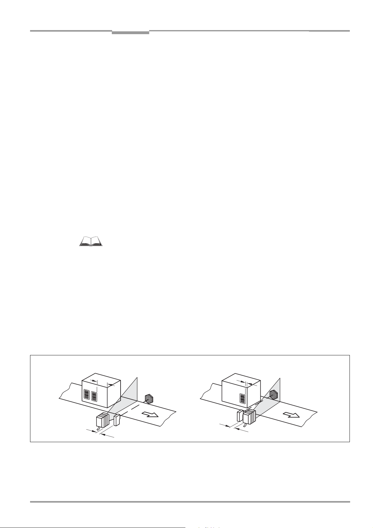
Operating Instructions Chapter 4
CLV 42x bar code scanner
Installation
1. Activate the operating mode as described in Chapter 6.5.3 Adjusting mode, Page 6-18.
2. Position the CLV in such a way that the center of the scan line (indicated by the end of
the visible scan line, code position CP = 50) is located at the center of the bar code, or
at the center of the field for all codes if several bar codes are used.
Show CP-limits
The "Show CP-limits" operating mode enables you to test whether a limit placed on the
active evaluation range of the scan line via parameterization has had the desired effects.
For this purpose, the CLV alternately masks out a certain part of the scan line corresponding
to the selected minimum and maximum values of the code position.
For information on calling up this operating mode and for checking procedures, see
Chapter 6.5.4 Show CP-limits, Page 6-19.
4.4 Installing external components
4.4.1 Installing the CDB 420 or CDM 420 connection module
1. Install the CDB 420 or CDM 420 connection module near the CLV. The distance
between the CDB 420 or CDM 420 and CLV must not exceed 10 m (32.8 ft).
2. Install the CDB 420 or CDM 420 in such a way that the device can be accessed when
opened. The terminal interface of the CLV is accessed via the internal "Aux" connector.
Detailed information on the installation and electrical installation procedures is provided in
the “CDB 420 Connection Module“ Operating Instructions (order no.
German/English version) respectively in the “CDM 420 Connection Module“ Operating
Instructions (order no.
8 010 004, German/English version).
4.4.2 Installing the external reading pulse sensor
If the CLV is triggered by an external reading pulse sensor, the sensor must be mounted in
the vicinity of the CLV. The "Sensor 1" switching input is selected as the default trigger
source for this trigger type.
Fig. 4-10 shows two examples of where a photoelectric reflex switch can be installed. This
depends on the distance a from the bar code to the front edge of the object. Depending on
the application, you may need to attach the sensor in such a way that bar codes on objects
of different sizes can be read completely during the reading interval.
Bar code in the middle or at the end of the moved object
a
8 010 001,
Bar code at the beginning of the moved object
a
b
Fig. 4-10: Line scanner: installation example for the external reading pulse sensor
8 009 981/O078/16-08-2004 © SICK AG · Division Auto Ident · Germany · All rights reserved 4-9
b < a
b
b < a
Page 38

Chapter 4 Operating Instructions
Installation
CLV 42x bar code scanner
1. Attach the reading pulse sensor to the installation location.
2. Connect the reading pulse sensor to the "Sensor 1" switching input of the CLV via the
CDB 420 or CDM 420 connection module (see
1" switching input, Page 5-8).
3. Connect the CLV to the CDB 420 or CDM 420 connection module and switch on the
power supply to the module (see
Page 5-5).
After the CLV has started, it emits a tone to indicate that the self-test was successful.
After a short while, it outputs two consecutive tones to indicate that it has switched to
Reading mode. The "Device Ready" LED lights up.
4. Connect the PC to the terminal interface of the CLV. For this purpose, connect a 3-core
RS
232 data cable to the internal 9-pin "Aux" plug of the module. (See Chapter 5.5.6
Connecting the PC, Page 5-7.)
5. Start Windows and "CLV Setup" on your PC (see Chapter 10.4.3 Starting "CLV Setup",
Page 10-10).
6. From the VIEW menu, choose READING MODE.
The Terminal Emulator window is then displayed. The CLV is in Reading mode.
Monitor the reading result during each of the subsequent steps!
7. Move objects with bar codes into the CLV reading field manually under realistic
conditions.
8. Check whether the reading result and trigger pulse are correct.
9. Repeat the procedure with the conveyor switched on.
Check whether the reading procedure is synchronized with the approaching objects.
Chapter 5.5.3 Connecting the power supply,
Chapter 5.5.7 Connecting the "Sensor
Parameterizing an external sensor as a trigger source (N/A with default setting):
1. Select the DEVICE CONFIGURATION tab.
2. Click the READING TRIGGER PARAMETERS button.
The READING TRIGGER PARAMETERS dialog window is then displayed.
3. Choose SENSOR INPUT (ACTIVE HIGH) in the READING TRIGGER SOURCE section and activate
the dialog box.
4. Perform a download to the CLV. This is done by clicking in the toolbar.
The DOWNLOAD PARAMETER dialog window is displayed.
5. Confirm the dialog window by selecting the PERMANENT save option.
The CLV operates with the "Sensor 1" switching input as an external trigger source.
The reading pulse starts when power is applied.
4.4.3 Installing the polling reflector
The reading pulse can also be triggered by the presence of an object in the reading field,
independent of an external reading pulse sensor, by using the "Reflector Polling" pulse
mode of the CLV. In order to do so, attach one of the two polling reflectors (special bar
codes) included with the device opposite the CLV behind the conveyor belt (
Table 4-2 lists the permissible range values for the polling reflectors. The pulse type is not
selected in the default setting.
Fig. 4-11).
4-10 © SICK AG · Division Auto Ident · Germany · All rights reserved 8 009 981/O078/16-08-2004
Page 39

Operating Instructions Chapter 4
CLV 42x bar code scanner
Installation
white blue
Polling
reflector
15°
Fig. 4-11: Line scanner: installation location of the polling reflector
Device type Reflector Range
CLV 420 white 100 to 320 mm (3.94 to 12.6 in) with
scanning frequency ≥ 800 Hz
blue with film 420 to 500 mm (16.5 to 19.7 in) with
scanning frequency 1000 Hz.
450 to 650 mm (17.7 to 25.6 in) with
scanning frequency 1200 Hz
blue without film 450 to 550 mm (17.7 to 21.7 in) with
scanning frequency 1000 Hz.
500 to 700 mm (19.7 to 27.6 in) with
scanning frequency 1200 Hz
CLV 421 white 200 to 600 mm (7.88 to 23.4 in) with
scanning frequency ≥ 600 Hz
blue with film 1000 to 1200 mm (39.4 to 47.3 in) with
scanning frequency ≥ 600 Hz
blue without film 1200 to 1450 mm (47.3 to 57.1 in) with
scanning frequency ≥ 600 Hz
CLV 422 white
blue with film
blue without film
not specified
50 mm = 1.97 in / 144 mm = 5.67 in
Table 4-2: Permissible range values for the polling reflectors
Explanation When reflector polling is used, the CLV activates the laser diode with every 20th scan and
checks whether it detects the reflector. If the reflector is visible, the CLV repeats the
procedure after the next 20 scans. If the reflector is concealed by an object entering the
reading field, the CLV starts the reading pulse. This pulse ends when the CLV detects the
reflector again. Following this, the CLV repeats the above procedure. When the CLV is
switched on, the polling reflector must be visible before the first reading pulse can start. The
CLV does not output the data content of the polling reflector in "Reading" mode.
Note This pulse mode is not suitable for applications where time is critical. The max. delay
between the reliable detection of the reflector and the start of the internal reading interval
is approx.
25 ms at a scanning rate of 800 Hz.
Adjusting the polling reflector roughly
1. Connect the CLV to the CDB 420 or CDM 420 connection module and switch on the
power supply to the module (see
Chapter 5.5.3 Connecting the power supply,
Page 5-5).
8 009 981/O078/16-08-2004 © SICK AG · Division Auto Ident · Germany · All rights reserved 4-11
Page 40
Chapter 4 Operating Instructions
Installation
CLV 42x bar code scanner
Once the CLV has started, it outputs a tone to indicate that the self-test was
successfully completed. Shortly afterwards, it outputs two tones consecutively to
indicate that it has assumed Reading mode. The "Device Ready" LED lights up.
2. Align the CLV optimally with the bar code on the object (see Chapter 4.3.2 Adjusting the
CLV, Page 4-7).
3. Choose a suitable polling reflector for the device type, as shown in Table 4-2,
Page 4-11. Other ranges available on request.
4. Secure the polling reflector directly opposite the CLV on a suitable base (movable
bracket, wall) temporarily so that the CLV has an unobstructed view of the reflector in
the gaps between the objects and can scan them reliably. The reflector must be in the
center of the scan line, see
Activating “Percentage Evaluation“ mode
5. From the VIEW menu, choose PERCENTAGE EVALUATION.
The dialog window for choosing the DISTANCE CONFIGURATION is then displayed.
6. Confirm the dialog window with "OK".
The Terminal Emulator is launched and displays the reading result continuously (see
Chapter 6.5.2 Percentage evaluation, Page 6-17).
Fig. 4-11.
Fine-adjusting and securing the polling reflector
7. Align the reflector with the CLV (not vice versa!) until a good read rate of 95 to 100 %
is reached. In doing so, prevent any surface reflection (see
between the CLV and the bar code, Page 4-4).
The CLV outputs the data content of the unconcealed polling reflector with the identifier
"REPO".
8. Once the device is in the final attachment position, remove the protective film from the
rear of the reflector and stick it to the base.
Activating “Reflector Polling pulse“ mode in the CLV
9. Select the DEVICE CONFIGURATION tab.
10. Click the READING TRIGGER PARAMETERS button.
The READING TRIGGER PARAMETERS dialog window is displayed.
11. Activate the REFLECTOR POLLING option in the READING TRIGGER SOURCE section.
12. Confirm the dialog box with "OK".
13. Perform a download to the CLV. This is done by clicking in the toolbar.
The DOWNLOAD PARAMETER dialog window is displayed.
14. Confirm the dialog window by selecting the PERMANENT save option.
The CLV is then operating in the "reflector polling" pulse mode.
15. Check whether the device operates correctly with objects moving under realistic
conditions on the conveyor belt. Readjust the reflector if necessary.
Chapter 4.2.7 Distance
4.5 Removing the device
1. Switch off the power supply to the CDB 420 or CDM 420 connection module.
2. Loosen the screws and remove the CLV connector from the CDB 420 or CDM 420
connection module.
3. Unscrew the CLV from the installation device.
When removing the device from service for the last time, please dispose of it in an
environmentally-friendly manner, as described in
4-12 © SICK AG · Division Auto Ident · Germany · All rights reserved 8 009 981/O078/16-08-2004
Chapter 7.3 Disposal, Page 7-2.
Page 41

Operating Instructions Chapter 5
CLV 42x bar code scanner
Electrical connection
5 Electrical connection
5.1 Overview of the connection sequence
• Connect the CLV to the SICK CDB 420 or CDM 420 connection module
• Connect the data and function interfaces of the CLV in the module
• Connect the PC to the connection module (at the terminal interface of the CLV)
• Connect the power supply to the connection module
5.2 Electrical connections and cables
The electrical connection for the CLV consists of a 15-pin D Sub HD plug. It supplies the
following interfaces:
• three serial data interfaces (host interface, CAN interface and terminal interface)
• two switching inputs (external reading pulse and multifunctional input)
• two switching outputs (for result status functions, or connecting to a PLC for example)
• power supply
Wire all the connections with copper cables with a minimum wire diameter of 0.09 mm2
(approx. 17 AWG)!
Photoelectric switch
Reading pulse
Path increment
Teach-in
Match code 1
End of reading
interval
5.2.1 Connections/cables for the CDB 420 or CDM 420 connection module
The CDB 420 or CDM 420 connection module is suitable for connecting the CLV to
peripherals (distribution function) and the power supply. The module can be used to
establish a connection to the host (point-to-point) or to integrate the device in a SICK CAN
Scanner Network.
The CDM 420 additionally supports the CLV for connecting to a field bus
system via an optional module (gateway)
Fig. 5-1 shows the connection principle of the CDB 420 or CDM 420 for one CLV.
CLV 42x
CDB 420 or CDM 420
connection module
AUX
HOST/PLC
“10 to 30 V DC“
10 to 30 V DC
PLC
– – cable if necessary
Fig. 5-1: Block diagram: connection of the CLV to the CDB 420 or CDM 420 connection module
8 009 981/O078/16-08-2004 © SICK AG · Division Auto Ident · Germany · All rights reserved 5-1
Page 42

Chapter 5 Operating Instructions
Electrical connection
CLV 42x bar code scanner
Connect and configure the CDB 420 or CDM 420 Connection Module as described in the
“
CDB 420 Connection Module“ Operating Instructions (order no. 8 010 001,
German/English version)
Instructions (order no.
respectively in the “CDM 420 Connection Module“ Operating
8 010 004, German/English version).
Note Diagramms showing you how to connect the CDB 420 and CDM 420 Connection Modules
are also available in the “CLV Connect“ PC program. This software is available on the
“Manuals & Software“ CD, which is included in the scope of delivery of the ICR.
The software can also be downloaded from the SICK home page (www.sick.de) at “Service&
Support/ Downloadpool“. It can be called up using a standard HTML browser (e. g. Internet
Explorer
TM
).
5.3 Connector pin assignment
56
1
111015
Pin Signal Function
1 10 to 30 V DC Power supply
2 RxD (Terminal) Terminal interface (receiver)
3 TxD (Terminal) Terminal interface (transmitter)
4 Sensor 2 Switching input, variable function
5 GND Ground
6 RD+ (RS 422/485) Host interface (receiver)
7 RD– (RS 422/485); RxD (RS 232) Host interface (receiver)
8 TD+ (RS 422/485) Host interface (transmitter)
9 TD– (RS 422/485); TxD (RS 232) Host interface (transmitter)
10 CAN H CAN-Bus (IN/OUT)
11 CAN L CAN-Bus (IN/OUT)
12 Result 1 Switching output, variable function
13 Result 2 Switching output, variable function
14 Sensor 1 Switching input for external reading pulse
15 SensGND Common ground for all inputs
– – Shield
Table 5-1: Pin assignment of the 15-pin D Sub HD plug
5-2 © SICK AG · Division Auto Ident · Germany · All rights reserved 8 009 981/O078/16-08-2004
Page 43

Operating Instructions Chapter 5
CLV 42x bar code scanner
Electrical connection
5.4 Preparations for electrical connection
5.4.1 Requirements for the host interface
The host interface of the CLV can be operated as an RS 422/485 or an RS 232 interface.
Table 5-2 shows the recommended maximum cable lengths as a function of the selected
data transfer rate.
Interface type Transfer rate Distance from host
RS 232 up to 19,200 bd max. 10 m (32.8.ft)
38,400 to 57,600 bd max. 3 m (9.84 ft)
RS 422/485
1) with suitable line termination according to specification
Table 5-2: Maximum cable lengths between the CLV and host
1)
To prevent interference, do not lay the cable parallel with power supply and motor
cables over long distances, e. g. in cable ducts.
max. 38,400 bd max. 1,200 m (3,937 ft)
max. 57,600 bd max. 500 m (1,640 ft)
5.4.2 Power supply
The CLV requires a power supply of 10 to 30 V DC (functional extra-low voltage) in
accordance with the standard IEC
generated by using a safety isolating transformer pursuant to IEC
364-4-41. The functional extra-low voltage can be
742. The CLV has a
power consumption of max. 3.5 W (when switching outputs are not connected).
The CLV is supplied with 10 to 30 V DC via the CDB 420 or CDM 420 connection module.
If an optional CMF 400 field bus gateway or a CMD 400 Connection Module Display is
additionally used in the CDM 420, the ICR is supplied with 18 to 30
V DC.
If the CMP 400 Power Supply Module is used in the CDM 420, a mains voltage of 100 to
250 V AC/50 to 60 Hz is required.
Note The CLV 42x is UL certificated when a class 2 power supply according to UL 1310 is used.
Power-up delay
The selected device number (default setting: 1) affects the power-up delay of the device.
This is useful if a large number of CLVs (e. g. in the SICK CAN Scanner Network) are supplied
from one power source.
Device number GN Power-up delay Device number GN Power-up delay
1; 11; 21; 31 0 ms 6; 16; 26 2,000 ms
2; 12; 22 400 ms 7; 17; 27 2,400 ms
3; 13; 23 800 ms 8; 18; 28 2,800 ms
4; 14; 24 1,200 ms 9; 19; 29 3,200 ms
5; 15; 25 1,600 ms 10; 20; 30 3,600 ms
Table 5-3: Power-up delay as a function of the device number GN
Table 5-3 contains a list of the available intervals.
Tip
The device number can be selected on the DEVICE CONFIGURATION tab in the CLV Setup
program.
8 009 981/O078/16-08-2004 © SICK AG · Division Auto Ident · Germany · All rights reserved 5-3
Page 44

Chapter 5 Operating Instructions
Electrical connection
CLV 42x bar code scanner
5.4.3 Non-SICK power pack/connections without the SICK connection module
If a non-SICK power supply unit is used instead of the CDB 420 or CDM 420, it must provide
a functional extra-low voltage in accordance with the standard IEC
continuous power output of at least 4 W.
364-4-41 and a
The output circuit must be reliably electrically isolated from the input circuit. Do do so,
use a safety isolating transformer pursuant to IEC
742.
The minimum wire cross-section for the power supply (pin 1/pin 5) is 0.15 mm2 (approx.
26 AWG).
Use the cable no. 6 010 137 with 15-pin D Sub HD socket and open wire ends to
connect the CLV. The color assignment of the wires is shown in
Table 5-4.
Note The CLV 42x is UL certificated when a class 2 power supply according to UL 1310 is used.
Pin Signal Wiring color
1 10 to 30 V DC red
2 RxD (Terminal) purple
3 TxD (Terminal) yellow
4 Sensor 2 red/black
5 GND black
6 RD+ (RS 422/485) light blue
7 RD– (RS 422/485); RxD (RS 232) blue
8 TD+ (RS 422/485) turquoise
9 TD– (RS 422/485); TxD (RS 232) green
10 CAN H gray
11 CAN L pink
12 Result 1 brown
13 Result 2 orange
14 Sensor 1 white
15 SensGND white/black
– Shield white/green
Table 5-4: Wiring color assignment of cable no. 6 010 137 (open end)
5.5 Making electrical connections
5.5.1 Overview of connection procedure
• Connect the power supply
• Connect the host interface
• Connect the PC (connect the terminal interface)
• Connect switching input "Sensor 1" and, if necessary, "Sensor 2" as well
• Connect switching outputs "Result 1" and "Result 2"
5.5.2 Auxiliaries
• Tools
• Digital measuring device (current/voltage measurement)
5-4 © SICK AG · Division Auto Ident · Germany · All rights reserved 8 009 981/O078/16-08-2004
Page 45

Operating Instructions Chapter 5
CLV 42x bar code scanner
Electrical connection
5.5.3 Connecting the power supply
If the CLV is powered via the CDB 420 or CDM 420 connection module, the power supply
does not have to be wired separately.
1. Ensure that the power supply to the CDB 420 or CDM 420 is switched off.
2. Connect the 15-pin plug on the CLV to the corresponding socket on the CDB 420 or
CDM 420
and screw it tightly. The connection cable can be extended by 2 m (6.56 ft)
using the extension cable no. 6 010 075.
The data and function interfaces of the CLV are connected to the connection module.
– or –
External power pack:
Connect the power supply to the red wire (pin 1, +10 to +30 V DC) and the black wire
(pin 5, GND) of cable no. 6 010 137. (See
also Table 5-4.)
5.5.4 Connecting the host interface
RS 232
CLV 42x
( )= 9-pin D Sub
plug at PC
RS 422
CLV 42x
Fig. 5-2: Connections of the host interface
Host
Host
Risk of damage to the interface module
Electronic components in the CLV may be damaged if the host interface is connected
incorrectly.
Connect the host interface as shown in Fig. 5-2.
Check the connections carefully before you switch on the CLV.
Connect the host interface on the CLV to the host using shielded cables (EMC
requirements). Ensure that the maximum cable lengths are not exceeded (
Table 5-2,
Page 5-3).
8 009 981/O078/16-08-2004 © SICK AG · Division Auto Ident · Germany · All rights reserved 5-5
Page 46

Chapter 5 Operating Instructions
Electrical connection
CLV 42x bar code scanner
In the default setting, the CLV communicates with the host via the host interface using the
values shown in
Parameter Value
Interface model RS 422/485
Data transfer rate 9,600 bd
Data bits 8
Parity none
Stop bits 1
Protocol SICK (start character: STX, stop character: ETX, no request for
Table 5-5: Communication parameters for the host interface (default setting)
Table 5-5.
repeat: none, timeout: 50 ms)
For connecting the host interface via the CDB 420 or CDM 420 Connection Module, see the
“CDB 420 Connection Module“ Operating Instructions (order no. 8 010 001, German/
English version)
(order no.
respectively the “CDM 420 Connection Module“ Operating Instructions
8 010 004, German/English version).
Terminating the RS 422 interface
The interface can be terminated in the CDB 420 or CDM 420 connection module.
See Operating Instructions for the "CDB 420 or CDM 420 connection module".
Activating the RS 232 interface
The RS 232 interface can be activated with the CLV Setup program:
1. Choose the HOST INTERFACE tab.
2. Choose the "RS 232" option from the HARDWARE drop-down list under DATA FORMAT.
3. Perform a download to the CLV. This is done by clicking in the toolbar.
The DOWNLOAD PARAMETER dialog window is displayed.
4. Confirm the dialog window by selecting the PERMANENT save option.
The CLV uses the RS 232 version of the host interface.
TIP The communication parameters can be changed, if necessary, on the HOST INTERFACE tab.
To do so, change the values under DATA FORMAT and INTERFACE PROTOCOL.
5.5.5 Connecting the CAN interface
For information on the connection and parameterization of the CLV for use in a SICK scanner
network or in a CANopen network, see the Operating Instructions
interface" (no. 8 009 180, English version).
"Application of the CAN
5-6 © SICK AG · Division Auto Ident · Germany · All rights reserved 8 009 981/O078/16-08-2004
Page 47

Operating Instructions Chapter 5
CLV 42x bar code scanner
Electrical connection
5.5.6 Connecting the PC
The CLV is operated and configured with the"CLV Setup" program. In order to do so, you
must connect the device to the PC via the terminal interface (auxiliary interface). Unlike the
host interface, the terminal interface has a permanent data format and a fixed data transfer
rate.
Fig. 5-3 shows how the terminal interface is connected. The cable length is not to
exceed 10 m (32.8 ft).
Tip
RS 232
CLV 42x
( )= 9-pin D Sub
plug at PC
Fig. 5-3: Connections of the terminal interface
PC
1. Switch off the PC and power supply to the SICK connection module.
2. Connect the PC to the internal, 9-pin ”Aux" plug of the connection module.
Use a 3-core RS 232 data cable (null modem cable) for this purpose, e. g.
no. 2 014 054 (RxD and TxD crossed).
– or –
If a non-SICK connection module is used:
Connect the PC as shown in Fig. 5-3.
3. Switch on the PC and power supply to the SICK connection module.
4. Set the communication parameters (see Chapter 10.4.3 Starting "CLV Setup",
Page 10-10).
In the default setting, the terminal interface outputs the reading result in "Reading
Diagnosis" mode.
You can change the operating mode to "Monitor Host Interface", "Auxiliary Input" or
“External Data String Input“ on the
AUXILIARY INTERFACE tab in the CLV Setup program.
8 009 981/O078/16-08-2004 © SICK AG · Division Auto Ident · Germany · All rights reserved 5-7
Page 48

Chapter 5 Operating Instructions
Electrical connection
CLV 42x bar code scanner
5.5.7 Connecting the "Sensor 1" switching input
If a reading procedure is to be triggered on the CLV by an external sensor, the reading pulse
sensor must be connected to the "Sensor 1" switching input. The trigger type is selected in
the default setting of the CLV.
Fig. 5-4 shows the connections for the "Sensor 1" switching
input. Table 5-6 contains the characteristic data for this input.
Connect the reading pulse sensor as is shown in Fig. 5-4.
CLV 42x V
V
S
= +10 to +30 V DC *) V
V
S
Fig. 5-4: Connections of the "Sensor 1" switching input
Switching mode Current at the input starts the reading interval on the CLV.
(default setting: active high, debouncing: max. 30 ms (standard))
Properties – optodecoupled, non-interchangeable
– can be connected to PNP output on a sensor
Electrical values Low: –1V ≤ Vi ≤ +1 V High: +3 V ≤ |Vi| ≤ +28 V
–0.3 mA ≤ Ii ≤ +0.3 mA +1.4 mA ≤ |Ii| ≤ +18 mA
Table 5-6: Characteristic data of the "Sensor 1" switching input
S
V
i
= 28 V!
imax
PNP sensor
V
S
Tip
You can change the switching mode (polarity, debouncing, response for first pulse after
power-up) of the "Sensor 1" switching input on the
DEVICE CONFIGURATION tab in the CLV
Setup program.
Click the READING TRIGGER PARAMETERS button. Edit dialog window.
Download all changes to CLV.
For connecting the switching input via the CDB 420 or CDM 420 Connection Module, see
the “CDB 420 Connection Module“ Operating Instructions (order no.
German/English version) respectively the “CDM 420 Connection Module“ Operating
Instructions (order no.
8 010 004, German/English version).
Note An external pulse is not required for "Percentage Evaluation" mode.
5.5.8 Connecting the "Sensor 2" switching input
The input has the following functions:
• Trigger source for teaching in the match code 1
• Conveyor increment input
• External trigger source for end of the reading interval
• Trigger source for switching over the dynamical reading configuration
8 010 001,
5-8 © SICK AG · Division Auto Ident · Germany · All rights reserved 8 009 981/O078/16-08-2004
Page 49

Operating Instructions Chapter 5
CLV 42x bar code scanner
Electrical connection
The "Teach-in match code" function is selected in the default setting.
The characteristic data is identical to that for the "Sensor 1" input (Table 5-6).
Fig. 5-5 shows the connections of the switching input.
Connect the sensors as is shown in Fig. 5-5.
Tip
CLV 42x V
V
S
V
= +10 to +30 V DC *) V
V
S
Fig. 5-5: Connections of the "Sensor 2" switching input
S
i
= 28 V!
imax
PNP sensor Switch
V
S
For connecting the switching input via the CDB 420 or CDM 420 Connection Module, see
the “CDB 420 Connection Module“ Operating Instructions (order no.
8 010 001,
German/English version) respectively the “CDM 420 Connection Module“ Operating
Instructions (order no.
8 010 004, German/English version).
The function assigned to the "Sensor 2" input can be modified on the DEVICE CONFIGURATION
tab in the CLV Setup program.
Click the FUNCTION SENSOR 2 drop-down list and choose the required function.
Download all changes to CLV.
The connections and procedure for teaching in match code 1 are described in
Chapter 10.9.1 Triggering the teach-in match code 1 via the "Sensor 2" switching input,
Page 10-26.
5.5.9 Connecting the "Result 1" and "Result 2" switching outputs
The two switching outputs can be assigned different functions for outputting result statuses
independently of each other. If the assigned event occurs during the reading procedure, the
corresponding switching output becomes live at the end of the reading pulse for the
selected pulse duration. The pulse duration is identical for both outputs.
The "Result" LED is linked to the "Result 2" output and lights up in "Reading" mode for the
selected pulse duration and function of the result status display (default setting: "Good
Read", 100 ms).
Fig. 5-6, Page 5-10 shows an example of how the "Result 1" switching output can be
connected. Table 5-7 describes the characteristic data for the outputs. This data is identical
for both outputs.
Connect the outputs as shown in Fig. 5-6.
8 009 981/O078/16-08-2004 © SICK AG · Division Auto Ident · Germany · All rights reserved 5-9
Page 50
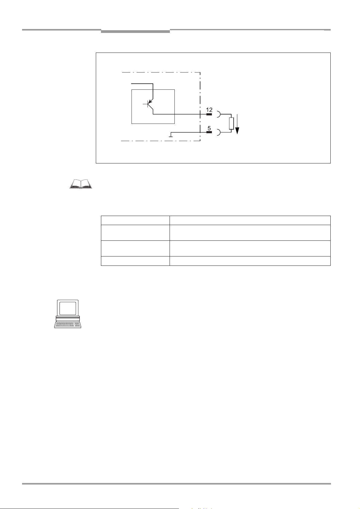
Chapter 5 Operating Instructions
Electrical connection
CLV 42x bar code scanner
CLV 42x
V
S
Pulse duration
"Result 1"
based on setting:
– 10 ms to 990 ms
–00: static
(to the end of the
V
o
next reading pulse)
Structure of output
Result 2 (pin 13)
V
= + 10 to +30 V DC
S
same as output Result 1
Fig. 5-6: Connections of the "Result 1" switching output
For connecting the switching outputs via the CDB 420 or CDM 420 Connection Module, see
the “CDB 420 Connection Module“ Operating Instructions (order no.
8 010 001,
German/English version) respectively the “CDM 420 Connection Module“ Operating
Instructions (order no.
8 010 004, German/English version).
Switching mode PNP-switching with respect to the power supply V
S
Characteristics short-circuit-proof + temperature-protected,
not electrically isolated from V
Function assignment
(default setting)
Result 1: "Device Ready (static)", polarity: not inverted
Result 2: "Good Read" (100 ms), polarity: not inverted
Electrical values 0 V ≤ Vo ≤ V
Guaranteed: (VS −1.5 V) ≤ Vo ≤ VS at Io ≤ 100 mA
S
S
Table 5-7: Characteristic data of the "Result 1" and "Result 2" switching outputs
Note If the "Device Ready" function is chosen, the CLV outputs a static pulse in Reading mode.
Tip
The output function, pulse duration (timer) and polarity of the signals can be changed on the
DEVICE CONFIGURATION tab in the CLV Setup program.
Click the RESULT OUTPUT PARAMETERS button. Edit dialog box.
Download all changes to CLV.
Recommendation To check the switching functions using a high-impedance digital voltmeter, power the
outputs.
This prevents incorrect voltage values/switching statuses from being displayed.
5-10 © SICK AG · Division Auto Ident · Germany · All rights reserved 8 009 981/O078/16-08-2004
Page 51

Operating Instructions Chapter 6
CLV 42x bar code scanner
Operation
6 Operation
6.1 Overview of procedure for starting up the CLV
• Start up the CLV with the factory default settings (Quick Start).
With this configuration, the CLV can be operated without being connected to a PC.
• Connect the PC. See Chapter 5.5.6 Connecting the PC, Page 5-7 and Chapter 10.4
Installation and operating instructions for the PC-based "CLV Setup" program,
Page 10-7.
• Configure (parameterize) the CLV for the desired application.
6.2 Default settings
Table 6-1, Page 6-2 shows an overview of the factory default settings of the CLV. The
default parameters are such that the CLV can be put into operation either straight away or
following a few minor adjustments. A PC is not required for startup with the default settings.
The default settings of the parameters are stored permanently both in the CLV (ROM) and
in the CLV Setup database. They can be loaded into the RAM of the CLV or displayed on the
tabs of CLV Setup at any time.
Displaying and printing out complete default settings in CLV Setup
1. Choose FILE and SAVE AS, and enter a file name in the dialog window that appears.
CLV Setup saves the current settings in a configuration file "*.scl".
2. Click in the toolbar.
CLV Setup loads the default settings from its internal database and displays them on
the tabs.
3. Click in the toolbar.
The PRINT FILE dialog window is then displayed.
4. If desired, a comment can be entered in the input field for the header of the printout.
Confirm the dialog window with "OK".
The PRINT dialog window for configuring the printer is then displayed.
5. Edit the dialog window accordingly and confirm.
CLV Setup prints out all of the default settings in the form of a table. The header contains
the company and user names that were entered during the CLV Setup installation routine.
8 009 981/O078/16-08-2004 © SICK AG · Division Auto Ident · Germany · All rights reserved 6-1
Page 52
Chapter 6 Operating Instructions
Operation
CLV 42x bar code scanner
6.2.1 Default settings: line/raster scanner CLV 42x
Parameter Default setting
Active code types Code 39, 2/5 Interleaved, Code 128
Code length freely assignable (2/5 Interleaved: interval 4 to 50 characters)
Quiet zone Start/stop ratio, automatic
Min./max. code position 0/100 CP
Multiple read 3
Min./max. no. codes 1
Scanning frequency 700 Hz
Min. reading distance 60 mm (2.36 in)
Reading pulse source Start: "Sensor 1" switching input (active: high); end: "Sensor 1" switching input
"Sensor 2" switching input Focus Control 1
"Sensor 1" switching input Start and end of reading pulse (level: active high), debouncing 20 to 30 ms
Switching outputs Not inverted; pulse duration: 100 ms
Status output function Result 1: "Device Ready" (static), Result 2: "Good read"
Beeper Status output function: "Good read", volume: low
Arrangement to host Standalone
Output of the reading result Host interface
Device number 1
Host interface (type) RS 422/485
Protocol NAK ; start character: STX, stop character: ETX
Transfer rate 9,600 bd
Data format 8 data bits; no parity; 1 stop bit
Output format Good Read: Header: blank; Code-Info/Separator: blank; Terminator: blank;
No Read: Code-Info/Separator and error string
Error string: NOREAD
Output sorting in accordance with code position
Output time Reading result: end of reading pulse Code-Info/Separator: after code
Test string not activated
Terminal interface RS 232; 9,600 bd; 8 data bits; no parity; 1 stop bit (values cannot be changed)
Function Reading diagnosis
Table 6-1: Extract: Default parameter settings of the line/raster scanner CLV 42x
6-2 © SICK AG · Division Auto Ident · Germany · All rights reserved 8 009 981/O078/16-08-2004
Page 53

Operating Instructions Chapter 6
CLV 42x bar code scanner
Operation
6.3 Quick start
A PC need not be connected when the CLV is operated with the factory default settings.
Code 39, 2/5 Interleaved, and Code 128 are the default code types enabled (free code
lenght, 2/5 Interleaved: interval 4 to 50 characters).
6.3.1 Starting up the line/raster scanner with the factory default settings
1. Connect the CLV to the SICK CDB 420 or CDM 420 connection module.
2. Connect the reading pulse sensor (e.g. photoelectric switch, switch) to the "Sensor 1"
switching input of the CLV via the CDB 420 or CDM 420. See
the "Sensor 1" switching input, Page 5-8.
3. Switch on the power supply to the CDB 420 or CDM 420.
Once the CLV has started, it outputs a tone to indicate that the self-test was
successfully completed. Shortly afterwards, it outputs two tones to indicate that it has
assumed reading mode. The "Device Ready" LED lights up. The "Result 1" ("Device
Ready") output switches.
4. Start the reading pulse: block the light path of the photoelectric switch or close the
switch.
The "Laser On" LED lights up. The CLV switches the laser diode on and the red scan
line appears.
5. Present the bar code pattern from Fig. 6-1 to the CLV at the reading distance specified
in Table 6-2.
6. Align the bar code in such a way that the red scan line is almost at a 90° angle to the
bars.
7. End the reading pulse: unblock the light path of the photoelectric switch or open the
switch.
The "Laser On" LED is extinguished. The CLV switches off the laser diode.
The CLV confirms that the bar code was read successfully by outputting a tone via the
beeper. The "Result" LED lights up for duration of 100 ms. The "Result 2" (Good read)
output switches for the duration of 100
ms.
The CLV can now be operated with the factory default settings.
The device can be switched off without the configuration data being lost as no changes have
been made to the parameter set.
Chapter 5.5.7 Connecting
0123412345
Fig. 6-1: Bar code pattern (code 39; module width 0.35 mm (13.8 mil); print ratio 2:1)
Device types Scan procedure Reading distance
CLV 420
CLV 421 Line/raster scanner approx. 250 mm (9.85 in)
CLV 422 Line/raster scanner approx. 100 mm (3.94 in)
Table 6-2: Reading distances for module width 0.35 mm (13.8 mil), default settings
8 009 981/O078/16-08-2004 © SICK AG · Division Auto Ident · Germany · All rights reserved 6-3
Line/raster scanner approx. 200 mm (7.88 in)
Page 54

Chapter 6 Operating Instructions
Operation
CLV 42x bar code scanner
6.4 Configuration (parameterizing)
The CLV is configured locally in accordance with the application at hand. The read, evaluation
and output characteristics can be parameterized as required. The factory default settings or
an application-specific parameter set of the CLV are in effect before changes are made.
The CLV supports four different configuration methods:
• Configuration via the "CLV Setup" program and the CLV Assistant
(parameter values are set via the serial interface).
• Configuration via AutoSetup
(reading and code configurations for a bar code are adapted automatically via the
optical interface (reading window)),
see Chapter 6.4.4 Configuring the CLV with AutoSetup, Page 6-10.
• Configuration via profile bar codes
(parameter values are set via the optical interface (reading window)),
see Chapter 10.5 Configuring the CLV with profile bar codes, Page 10-17.
• Configuration via command strings
(parameter values are set via the serial interface),
see Chapter 10.6 Configuring the CLV with command strings, Page 10-22.
In Parameter mode, the CLV only outputs a reading result with AutoSetup.
6.4.1 Configuring CLV with the user interface of CLV Setup
To be able to use "CLV Setup", a PC has to be connected and the program installed on it.
The procedure for connecting the PC to the CLV is described in
the PC, Page 5-7. Installation and startup of "CLV Setup" and operation of the user interface
are described in the appendix. See Chapter 10.4 Installation and operating instructions for
the PC-based "CLV Setup" program, Page 10-7.
Transferring parameter sets between CLV Setup and the CLV
Upload
When the CLV is being parameterized, CLV-Setup runs in the offline mode. To be able to
modify the current parameter set of the CLV, this first has to be loaded to CLV-Setup from
the CLV. This procedure is referred to as an
Setup always loads a complete copy of the current CLV parameter set. This parameter set
remains unchanged until it is overwritten by CLV-Setup.
With the help of the context menu (right mouse button), only the parameter just edited can
be loaded ("Upload parameter") or from version 3.6 all parameters of one tab or one dialog
box ("Upload parameters of this view") from the CLV’s memory (RAM).
Download
Changes made to the current parameter set in CLV-Setup do not take effect until the parameter set has been transferred to the CLV. CLV-Setup always sends a copy of the complete parameter set to the CLV, i. e. all of the existing parameter values in the CLV are
overwritten. The procedure for transferring and saving the parameter values in the CLV is
referred to as a
With the help of the context menu (right mouse button), only the parameter just edited
("Download parameter") or from version 3.6 all parameters of one tab or one dialog box
("Download parameters of this view") will be
(RAM). To finish the parametrization done by this way all parameters must be download
again to the CLV with the "Permanent" option.
download ("Download to CLV").
upload ("Upload from CLV") during which CLV-
temporarily loaded into the CLV’s memory
Chapter 5.5.6 Connecting
6-4 © SICK AG · Division Auto Ident · Germany · All rights reserved 8 009 981/O078/16-08-2004
Page 55

Operating Instructions Chapter 6
CLV 42x bar code scanner
Operation
Loading complete parameter set from the CLV (upload)
Click in the toolbar.
CLV Setup loads the current CLV parameter set from the RAM of the CLV to its database
and displays the values on the tabs.
The "Device Ready" LED is extinguished during the upload.
If the "CLV Setup" program does not recognize the parameters transferred during the
upload, it outputs a warning. Unknown parameters can be edited on the
EXTRAS tab by
following the conventions for command strings. When the parameter set is saved, these
parameters are also taken into account.
Transferring the complete parameter set to the CLV and saving it (download)
1. Click in the toolbar.
The "Device Ready" LED is extinguished.
CLV Setup copies the parameter set to the RAM of the CLV.
The DOWNLOAD PARAMETERS dialog window with the save options is then displayed.
PERMANENT: CLV Setup copies the parameter set to the RAM and to the EEPROM of
the CLV.
TEMPORARY: CLV Setup copies the parameter set to the RAM only. The changes are
lost when the CLV power supply is switched off.
2. Confirm the dialog box with the desired save option.
The "Device Ready" LED lights up again.
The new parameter set is saved in the CLV, permanentely or temporarily dependent on the
selected option.
Saving the parameter set in CLV Setup
1. To save the modified parameter set as a new configuration file in CLV Setup, or to
overwrite an existing file, choose
FILE and SAVE AS.
The SAVE AS dialog window is then displayed.
2. Enter the file name in the dialog window (file extension "*.scl") and confirm the entry.
The new parameter set is now saved in CLV Setup in the subdirectory "data".
6.4.2 Function of tabs in CLV Setup (overview)
Reading Configuration
This tab (and additional dialog windows) are used to set the following:
• Scanning frequency and min. reading distance
• Quiet zone
• Adapting the reading function to the quality of the bar code
• Limitation of the evaluation range of the scan line
• Activation of dynamical reading configurations
Device Configuration
This tab (and additional dialog windows) are used to set the following:
• Device number
• Source of the reading pulse
• Output time of the reading result referred to the start of the reading pulse
• Laser timeout
• Encoder parameters
8 009 981/O078/16-08-2004 © SICK AG · Division Auto Ident · Germany · All rights reserved 6-5
Page 56

Chapter 6 Operating Instructions
Recommendation To enhance the reading reliability with fast applications, only activate those code types and
Operation
CLV 42x bar code scanner
• Output filter
• Physical arrangement for data output via the host interface (standalone, master/slave)
• Functional assignment of the "Sensor 2" switching input
• Functional assignments of the "Result 1" and "Result 2" switching outputs
• Functional assignment and volume of the beeper
• Mode for programming match code 1 (teach-in) via the "Sensor 2" switching input
• Code comparison
Code Configuration
This tab (and additional dialog boxes) are used to set the following:
• Activation of evaluation routines for individual code types
• Number of identical reads (multiple reads)
• Minimum and maximum number of bar codes to be read/output
• Activation of comparison of code position for the separation of identical bar codes
code lengths that are actually relevant.
Host Interface
This tab (and additional dialog boxes) are used to set the following:
• Destination of result output
• Active physical interface (RS 422/485, RS 232)
• Data format and transfer rate
• Data transfer protocol
• Start and stop characters of the interface protocol
Data Strings
This tab (and additional dialog boxes) are used to set the following:
• Data output format of the host or CAN interface
• Constants and reading diagnosis data in the “Header“, “Code Info/Separator“, “Splitter“
and “Terminator“ blocks
• Arrangement of the “Code Info/Separator“ blocks in the data string
• Output format for no reads and contents of the error string
• Test string function
• Output sequence and sort criteria for reading more than one bar code per reading pulse
• Activation and structure of format mask
• Structure of external data strings which have to be integrated as seperate reading
results
Auxiliary Interface
This tab is used to set the following:
• Operating mode of the terminal interface
CAN Interface
This tab (and additional dialog boxes) are used to set the following:
• Operating mode of the CAN interface
• Data transfer rate
6-6 © SICK AG · Division Auto Ident · Germany · All rights reserved 8 009 981/O078/16-08-2004
Page 57

Operating Instructions Chapter 6
CLV 42x bar code scanner
Operation
• Type of logical data network of connected CLVs
• Use of switching inputs/outputs of the CLV as CANopen Digital I/O
Fieldbus Gateway
This tab (and additional dialog boxes) are used to set the following:
• Data interface of the CLV to be connected to the gateway in the CDM 420
• Type of fieldbus
• Special fieldbus parameters
Extras
This tab is used to edit parameters that were not recognized by CLV Setup after an upload.
Note The online "CLV Setup Help" contains a detailed description of the functions of the
parameters and their valid entries. S
ee Chapter 10.4.8 Online help – CLV Setup Help,
Page 10-14.
6.4.3 Parameterization guide
Overview of parameterization procedure
• Parameterize optical reading characteristics of the scanner
• Set up reading pulse
• Parameterize the evaluation characteristics of the decoder
• Parameterize output characteristics (data, result status)
• Define the function of the terminal interface
When the CLV is started up for the first time, the factory default settings are in effect. The
following parameters must then be set:
a) Parameterizing optical reading characteristics
• Scanning frequency READING CONFIGURATION tab READING PARAMETERS section
• Min. reading distance READING CONFIGURATION tab MINIMUM DISTANCE section
• Quiet zone READING CONFIGURATION tab QUIET ZONE section
• Poor quality bar code print READING CONFIGURATION tab CODELABEL QUALITY section.
Alternative: Enable Dynamic Reading Configuration READING CONFIGURATION tab
DYNAMIC READING CONFIGURATION ACTIVE
• Limite evaluation range of scan line READING CONFIGURATION tab CODE POSITION
section
8 009 981/O078/16-08-2004 © SICK AG · Division Auto Ident · Germany · All rights reserved 6-7
Page 58

Chapter 6 Operating Instructions
Operation
CLV 42x bar code scanner
b) Parameterizing reading pulse source
Action Settings
1. Reading pulse: choose source for start DEVICE CONFIGURATION tab
READING TRIGGER PARAMETERS button
READING TRIGGER SOURCE section
– Sensor Input (Active High) or
– Sensor Input (Active Low) or
– Serial Interface or
– Free Running with Timeout or
– Reflector Polling
2. Pulse source "Sensor Input 1":
Select debouncing and response at first
trigger
READING TRIGGER PARAMETERS button
DEBOUNCING SENSOR section
– Standard or
– Fast or
– User defined
FIRST TRIGGER section
– Edge or
– Level
3. Pulse source "Serial Interface":
choose trigger character
4. Pulse source "Free Running":
choose timeout
5. Pulse source "Continuous Read":
choose timeout
6. Reading pulse: choose source for end READING TRIGGER PARAMETERS button
READING TRIGGER PARAMETERS button
SERIAL INTERFACE section
– Standard Trigger or
– Single Character
READING TRIGGER PARAMETERS button
END OF LABEL/FREE RUNNING section
– Timeout
READING TRIGGER PARAMETERS button
END OF LABEL/FREE RUNNING section
– Timeout
END OF READING INTERVAL section
– Generated by Trigger Source or
– Timer
7. Pulse source "Sensor Input 1":
choose source for end
READING TRIGGER PARAMETERS button
ASSIGNMENT OF SENSOR INPUTS section
SENSOR 2 listing field
– Reading trigger stop (active high) or
– Reading trigger stop (active low)
Table 6-3: Guide: parameterizing reading pulse source
c) Parameterizing laser timeout
Action Settings
1. Select the duration for the laser timeout DEVICE CONFIGURATION tab
READING TRIGGER PARAMETERS button
LASER TIMEOUT section
– Duration
2. Deactivate the laser timeout
(laser diode is always active when pulsing,
regardless of the pulse duration)
Table 6-4: Guide: parameterizing laser timeout
LASER TIMEOUT section
– Click (deactivate) the ACTIVE checkbox
6-8 © SICK AG · Division Auto Ident · Germany · All rights reserved 8 009 981/O078/16-08-2004
Page 59

Operating Instructions Chapter 6
CLV 42x bar code scanner
Operation
d) Parameterizing evaluation characteristics
• Activate code types for evaluation CODE CONFIGURATION tab SYMBOLOGIES section
and
SYMBOLOGY PARAMETERS button
• Activate code comparison DEVICE CONFIGURATION tab CODE COMPARISON section
• Mode for TEACHING IN match code 1 via the "Sensor 2" switching input DEVICE
C
ONFIGURATION tab TEACH-IN section
• Set output time of the reading result DEVICE CONFIGURATION tab READING TRIGGER
P
ARAMETERS button output for GOOD READ section
Separation of identical bar codes (same code type/identical contents)
No. of bar codes per object Line/raster scanner
1. Number n = 1 CODE CONFIGURATION tab
CODE POSITION section
– Deactivate COMPARE!
2. Number n > 1:
– Same code type
– Contents different or identical
3. Number n > 1:
– Code type different
– Contents different or identical
Table 6-5: Guide: settings to be made for the evaluation of identical bar codes
CODE POSITION section
– Activate COMPARE!
NUMBER OF CODES section
– MINIMUM
– MAXIMUM
CODE POSITION section
– Deactivate COMPARE!
NUMBER OF CODES section
– MINIMUM
– MAXIMUM
e) Parameterizing output characteristics
Result status:
• Define function of result status output of "Result 1" and "Result 2" switching outputs
DEVICE CONFIGURATION tab RESULT OUTPUT PARAMETERS button
• Define function of result status output and volume of beeper DEVICE CONFIGURATION
tab RESULT OUTPUT section and READING OUTPUT PARAMETERS button
Main data interface (general):
• Destination of the reading result HOST INTERFACE tab DESTINATION OF RESULT DATA
STRINGS section
• Filter reading result DEVICE CONFIGURATION tab ODETTE FILTER section
• Sort reading result DATA STRINGS tab OUTPUT SEQUENCE SORT section
• Masking of the reading result DATA STRINGS tab FORMAT MASK section
Host Interface:
• Arrangement in the data network DEVICE CONFIGURATION tab ARRANGEMENT section
• Physical interface HOST INTERFACE tab DATA FORMAT section
• Communication parameters HOST INTERFACE tab DATA FORMAT section
• Protocol HOST INTERFACE tab INTERFACE PROTOCOL section
8 009 981/O078/16-08-2004 © SICK AG · Division Auto Ident · Germany · All rights reserved 6-9
Page 60

Chapter 6 Operating Instructions
Operation
CLV 42x bar code scanner
Function of the CAN interface (alternative):
See Operating Instructions "Application of the CAN Interface" (no. 8 009 180, English
version)
Data Connection to the CMF 400 Fieldbus gateway:
• Choose the fieldbus system for each communication port FIELDBUS GATEWAY tab
HOST GATEWAY section and/or AUXILIARY GATEWAY section
• Communication parameters for the selected fieldbus system FIELDBUS GATEWAY tab
Data output string of host/CAN interface:
• Select contents of the “Header“, “Code Info/Separator“, “Splitter“ and “Terminator“
blocks
DATA STRINGS tab OUTPUT FORMAT section
• Position of the „Code Info/Separator“ block in data output string DATA STRINGS tab
CODE INFO/SEPARATOR section
• Set no read format DATA STRINGS tab READING DATA IN CASE OF ERROR section and
ERROR STRING section
• If necessary, parameterize/activate test string DATA STRINGS tab EXTERNAL DATA
S
TRING PARAMETERS section
• If necessary, parameterize the integration of an external data string into the reading
result
DATA STRINGS tab TEST STRING section
• Parameterize special functions DATA STRINGS tab SPECIALS button
f) Parameterizing auxiliary interface
• AUXILIARY INTERFACE tab
6.4.4 Configuring the CLV with AutoSetup
AutoSetup enables the reading and code configurations of the CLV to be adapted automatically to the application at hand. The following conditions must be fulfilled with regard to this:
• one bar code (code type, code length)
• fixed reading distance
• conveyor belt off (static reading)
The CLV determines the code type, code length and the most favorable scanning rate for
the bar code presented. This takes place in Free Running mode. Once AutoSetup has been
completed successfully, the CLV copies the parameter values determined to its parameter
set.
All other code types and code lengths are then disabled. If AutoSetup was not
completed successfully, the parameter set is not changed. The CLV does not read a
Pharmacode or any EAN/UPC types in AutoSetup. It does not respond to an external reading
pulse.
AutoSetup can be activated in three different ways in the CLV:
• via the user interface of CLV Setup
• by presenting profile bar code no. 10 (on the card supplied) to the optical interface
(reading window).
See Chapter 10.5.1 Activating AutoSetup with a profile bar code,
Page 10-17.
• via a command string (via the serial interface). See Chapter 10.6 Configuring the CLV
with command strings, Page 10-22.
While AutoSetup is running, the CLV outputs the step-by-step changes made to the
parameter values in the search mode and the determined diagnosis data via the terminal
6-10 © SICK AG · Division Auto Ident · Germany · All rights reserved 8 009 981/O078/16-08-2004
Page 61

Operating Instructions Chapter 6
CLV 42x bar code scanner
Operation
interface in the form of a list. The list can be displayed, for example, in the terminal emulator
of CLV Setup. Once AutoSetup has been completed, appropriate error messages are output
for diagnosed malfunctions in the event of a no read.
Explanation AutoSetup procedure
1. Starting at 400 Hz, the CLV increases its scanning frequency to 1,200 Hz in steps of
100 Hz. It evaluates the reading quality of 100 scans for each step.
2. The CLV performs verification reads +/– 50 Hz around the scanning frequency with the
highest reading quality.
3. It then copies the optimum scanning frequency, the code type and code length to its
parameter set.
Activating AutoSetup via the user interface of CLV Setup
In CLV Setup, AutoSetup can be started by choosing the appropriate menu path, via the
terminal emulator or as an executable device function (interactively). Due to the better
display of the progressing procedure, we recommend starting AutoSetup via the terminal
emulator.
Preparing AutoSetup:
1. Switch on the power supply of the CDB 420 or CDM 420 connection module (of the
CLV).
After the CLV has started, it emits a tone to indicate that the self-test was successful.
After a short while, it outputs two consecutive tones to indicate that it has switched to
reading mode. The "Device Ready" LED lights up.
2. Upload the current parameter set from the CLV with CLV Setup (the parameter set
initially contains the factory default settings).
CLV Setup displays the current values on the tabs.
3. AutoSetup overwrites important values in the current parameter set of the CLV.
Save the existing parameter set as a configuration file "*.scl" in CLV Setup before you
change the parameter settings.
See Chapter 6.4.1 Configuring CLV with the user
interface of CLV Setup, Page 6-4.
Performing AutoSetup:
1. Click in the toolbar.
The terminal emulator is launched. The CLV is in reading mode.
2. Present the application-specific bar code to the CLV at the maximum reading distance
for the application. Note the limits of the CLV here. See
reading field diagrams in
Chapter 10.2 Specification diagrams, Page 10-1.
To prevent surface reflections, rotate the bar code towards the CLV approximately 15°
away from the vertical axis. See
Fig. 4-7, Page 4-5.
3. Click AUTO SETUP under DEVICE MODE.
The CLV cancels reading mode. The "Device Ready" LED is extinguished.
The CLV then starts AutoSetup.
The red scan line appears when the "Laser On" LED lights up.
4. The CLV then runs AutoSetup and continuously displays the changes to the parameter
values in the terminal emulator (
Fig. 6-2, Page 6-12).
5. The CLV confirms that AutoSetup has been completed successfully by outputting two
consecutive tones via the beeper and activating the "Result" LED for 100 ms (default
setting). To begin with, it only overwrites the appropriate parameter values in the RAM.
The CLV returns to reading mode. The "Device Ready" LED lights up. The READING MODE
8 009 981/O078/16-08-2004 © SICK AG · Division Auto Ident · Germany · All rights reserved 6-11
Page 62

Chapter 6 Operating Instructions
Operation
CLV 42x bar code scanner
radio button in the terminal emulator is not, however, displayed as the active device
mode again. The CLV only evaluates the presented code type and length the next time
a bar code is read.
6. Perform an upload from the CLV. This is done by clicking in the toolbar.
CLV loads the current parameter set from the RAM of the CLV and displays the new
values in the tabs.
7. Perform a download to the CLV. This is done by clicking in the toolbar.
The DOWNLOAD PARAMETER dialog box is displayed.
8. Confirm the dialog box by selecting the PERMANENT save option.
The CLV saves the changes made to the parameter set permanently in the EEPROM.
9. Close the terminal emulator.
with:
Amp = amplifier setting
ScanFreq = scanning frequency
ReadRate = reading quality
CodeType = code type
CodeLen = code length
CodeStr = data contents of the bar code
Fig. 6-2: CLV Setup: AutoSetup displayed in the terminal emulator
AutoSetup canceled by the CLV in the event of a no read:
If the CLV was not able to execute AutoSetup successfully, it cancels the search mode after
the last increase made to the parameter values by outputting a long tone via the beeper.
Depending on the reason for AutoSetup being terminated, it outputs one of the following
error messages via the terminal Interface:
"No valid code found" (no valid bar code found or reading quality less than 75 %)
"Cancel AutoSetup" (AutoSetup terminates)
– or –
"More than one code found"
"Cancel AutoSetup" (AutoSetup terminates)
6-12 © SICK AG · Division Auto Ident · Germany · All rights reserved 8 009 981/O078/16-08-2004
Page 63

Operating Instructions Chapter 6
CLV 42x bar code scanner
Operation
The current parameter set in the CLV does not change.
The CLV returns to reading mode.
The "Device Ready" LED lights up.
Running AutoSetup again:
1. Click READING MODE under DEVICE MODE.
The CLV switches to reading mode.
2. Click AUTO SETUP under DEVICE MODE again.
The CLV then starts AutoSetup.
3. If AutoSetup is unsuccessful again, check whether the CLV is able to read the bar code
correctly (reading distance, tilt, more than one bar code in the reading field).
Terminating AutoSetup prematurely:
It is not possible to abort AutoSetup here.
To prevent parameter values in the RAM of the CLV from being overwritten, move the
bar code away from the reading field and wait for the CLV to output an error message
(AutoSetup must not supply invalid settings).
Checking parameter values stored in the CLV (after parameters are saved):
1. Switch the power supply of the connection module (of the CLV) off and on again.
2. Perform an upload from the CLV. This is done by clicking in the toolbar.
3. Check the values in the READING CONFIGURATION and CODE CONFIGURATION tabs.
Only one code type may be active on the CODE CONFIGURATION tab.
Note The CLV does not enter a real value in the parameter set for the parameter "Minimum Bar
Width", as it is not able to determine any absolute dimensions. This is why the value
displayed on the
READING CONFIGURATION tab does not match the actual conditions.
Checking the stored read and code configurations:
Once AutoSetup has been completed successfully, check the CLV settings as follows:
1. Click in the toolbar.
The TERMINAL EMULATOR is launched. The CLV is in reading mode.
2. Click PERCENT EVALUATION under DEVICE MODE.
The dialog box for the distance configuration is then displayed.
3. Confirm the dialog box with "OK".
The CLV starts the percentage evaluation and displays the reading quality of each set
of 100 scans continuously. See
Chapter 6.5.2 Percentage evaluation, Page 6-17.
4. Present the application-specific bar code at the distance taught in (at the minimum and
maximum reading distance if the bar code in the application is in a variable reading
range).
5. Check the reading quality in the terminal emulator. This should be between
70
and 100 %.
8 009 981/O078/16-08-2004 © SICK AG · Division Auto Ident · Germany · All rights reserved 6-13
Page 64

Chapter 6 Operating Instructions
Operation
CLV 42x bar code scanner
6.5 Operating modes and outputting the reading result
The following CLV operating modes/functions can be selected in CLV Setup:
Standard operating mode
• Reading mode
For startup
• Percentage evaluation
• Adjusting mode
For adapting device to application
• AutoSetup (automatic adaptation to reading conditions):
See Chapter 6.4.4 Configuring the CLV with AutoSetup, Page 6-10.
• Profile programming (configuration):
See Chapter 10.5.2 Profile programming, Page 10-19.
• Parameterization (configuration):
See Chapter 6.4.1 Configuring CLV with the user interface of CLV Setup, Page 6-4.
• Teach-in match code 1/activate match code comparison with "Sensor 2" switching input.
See Chapter 10.9.1 Triggering the teach-in match code 1 via the "Sensor 2" switching
input, Page 10-26.
• Show CP-limits
For monitoring purposes/correcting faults
• Displaying and editing operating data
• Reading diagnosis
• Monitor host interface
• Auxiliary input
• Self-test
6.5.1 Reading mode (standard operating mode)
The CLV performs a self-test after it has been switched on. It is then set to the reading mode
and confirms this by outputting two consecutive tones via the beeper. In the default setting,
the "Sensor 1" switching input is the (external) trigger source of the reading pulse. The
reading result is output by the CLV at the end of the reading pulse via the host interface
(default setting) and terminal interface.
The reading result of the terminal interface can be displayed in the CLV Setup terminal
emulator. The CLV terminal interface must be set to the
purpose. This mode is selected for the default setting. The reading result of the terminal
interface has a fixed, invariable format.
The READING MODE can be called up by choosing VIEW in the menu bar or via the terminal
emulator.
reading diagnosis mode for this
6-14 © SICK AG · Division Auto Ident · Germany · All rights reserved 8 009 981/O078/16-08-2004
Page 65
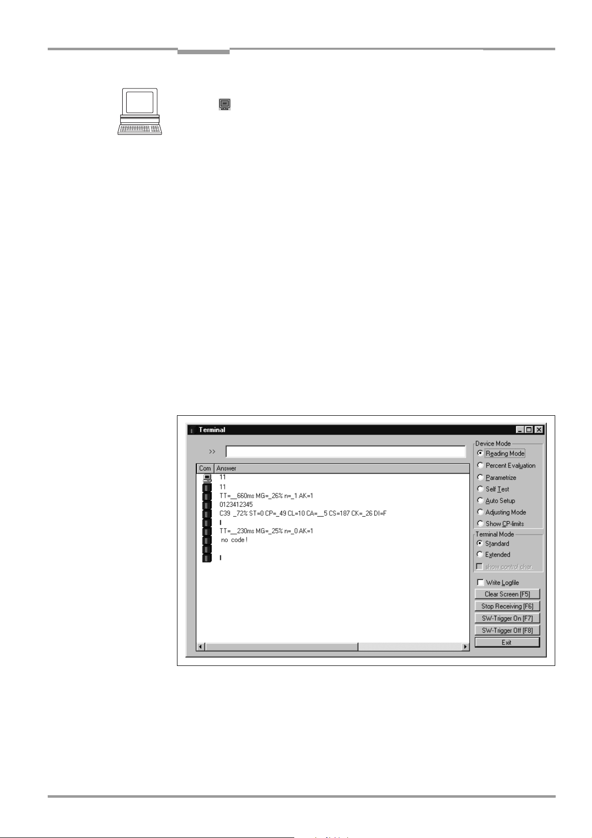
Operating Instructions Chapter 6
CLV 42x bar code scanner
Operation
Displaying the reading result in the terminal emulator
1. Click in the toolbar.
The TERMINAL EMULATOR dialog box is then displayed.
2. Click READING MODE under DEVICE MODE.
3. Present the bar code pattern from Fig. 6-1, Page 6-3 to the CLV and activate the
reading pulse. The "Laser On" LED lights up. The red scan line then appears.
See also Chapter 6.3.1 Starting up the line/raster scanner with the factory default
settings, Page 6-3.
4. Terminate reading pulse.
The CLV outputs a tone via the beeper to indicate that the reading result is displayed in
the window of the T
ERMINAL EMULATOR. The "Result" LED lights up for duration of 100 ms
(default setting).
Fig. 6-3 shows two examples of reading result output: "good read" and "no read". The
reading result comprises the data contents of the bar code(s) and the reading diagnosis
data
. Fig. 6-4 explains the structure and function of the reading diagnosis data for good
read, and Fig. 6-5 for no read.
Note The CLV only outputs several bar codes in the reading result of the host interface if the
parameterized minimum and maximum number of bar codes is > 1, and several bar codes
have been presented. The number of bar codes to be read/output for each reading interval
can be selected on the
CODE CONFIGURATION tab in the NUMBER OF CODES group.
The reading result of the host interface can also be displayed.
Chapter 6.5.7 Monitor host interface, Page 6-21 describes the procedure and the structure
of the read result in the default setting.
Fig. 6-3: CLV Setup: output of the reading result of the terminal interface
in terminal emulator
8 009 981/O078/16-08-2004 © SICK AG · Division Auto Ident · Germany · All rights reserved 6-15
Page 66
Chapter 6 Operating Instructions
Operation
CLV 42x bar code scanner
Successful read (good tead):
TT =__660 ms MG =_26% n =_1 AK = 1
0123412345
C39 _72% ST = 0 CP =_49 CL = 10 CA = __5 CS = 187 CK=_26 DI = F
with:
1st line: TT = Reading interval time
MG = Long-term mean value of identification quality
n = Number of recognized codelabels
AK = No. of distance configuration used
2nd line: 0123412345 = Data content of the bar code
3rd line: C39 = ID: Code 39
_72% = Identification quality
ST = Read status (ST = 0, Good read)
CP = Code position
CL = Code length (character count)
CA = Scanning expenditure
CS = Code security
CK = Code continuity
DI = Decoding direction
(F = scanning direction, R = opposite scanning direction)
Fig. 6-4: Reading result of the terminal interface: structure for "good read"
No read:
TT =__230 ms MG =__25% n =_0 AK = 1
no code!
with:
1st line: TT = Reading interval time
MG = Long-term mean value of identification quality
n = Number of recognized codelabels
AK = No. of distance configuration used
2nd line: no code! = No bar codes found!
Fig. 6-5: Reading result of the terminal interface: structure for "no read"
Note In the reading mode, the CLV does not output the contents of the polling reflector.
Triggering the reading pulse via the terminal emulator
In the default setting, the "Sensor 1" switching input is the (external) trigger source of the
reading pulse. For test purposes the reading pulse can also be triggered directly via the
terminal emulator of CLV Setup. To do so, a different trigger source must be selected
temporarily in the CLV.
1. Choose the DEVICE CONFIGURATION tab.
2. Click the READING TRIGGER PARAMETERS button.
The READING TRIGGER PARAMETERS dialog box is then displayed.
3. Click SERIAL INTERFACE under READING TRIGGER SOURCE.
4. Perform a download to the CLV.
To do so, click the SERIAL INTERFACE option again with the right mouse button and choose
6-16 © SICK AG · Division Auto Ident · Germany · All rights reserved 8 009 981/O078/16-08-2004
Page 67

Operating Instructions Chapter 6
CLV 42x bar code scanner
Operation
DOWNLOAD PARAMETER in the context menu.
CLV-Setup copies the parameter to the CLV temporarily.
The serial interface has been activated as the trigger source of the reading pulse and
is ready to receive appropriate commands (until the CLV is switched off).
5. Click in the toolbar.
The TERMINAL EMULATOR dialog box is then displayed.
The CLV is in reading mode.
6. Click the SW-TRIGGER ON button or press [F7].
CLV Setup sends a start command to the CLV.
The "Laser On" LED lights up. The red scan line then appears.
7. Present the bar code sample from Fig. 6-1, Page 6-3.
8. Click the SW-TRIGGER OFF button or press [F8].
CLV Setup sends a stop command to the CLV.
The "Laser On" LED is extinguished. The CLV switches off the laser diode.
The CLV outputs a tone via the beeper to indicate that the reading result is displayed in
the output window of the terminal emulator. The "Result" LED lights up for a duration of
100 ms (default setting).
6.5.2 Percentage evaluation
In the Percentage evaluation mode, the reading quality of bar codes which enter the reading
field of the CLV and are not moved (conveyor off) is assessed.
The CLV performs 100 scans in “Free Running“ mode and evaluates the reading quality. It
outputs the reading result continuously every 2 s via the
results can be displayed in the
terminal emulator of CLV Setup.
terminal interface. The reading
The Percentage evaluation mode can be called up by choosing VIEW in the menu bar or via
the terminal emulator.
1. Click in the toolbar.
The terminal emulator window is then displayed. The CLV is in reading mode.
2. Click PERCENT EVALUATION under DEVICE MODE.
The dialog box for choosing the distance configuration is then displayed.
3. Confirm the dialog box with "OK".
The "Device Ready" LED is extinguished. The CLV initiates the percentage evaluation
and outputs the reading results continuously. An example is shown in
Fig. 6-6,
Page 6-18.
4. Present the bar code pattern from Fig. 6-1, Page 6-3 and monitor the reading results
in the terminal emulator window.
The behavior of the "Result" LED also indicates the reading quality:
– LED is extinguished if reading quality is < 30 %
– LED flashes twice per second if the reading quality is 30 % to 70 %
– LED flashes five times per second if the reading quality is 70 % to 90 %
– LED is lit continuously if the reading quality is > 90 %
8 009 981/O078/16-08-2004 © SICK AG · Division Auto Ident · Germany · All rights reserved 6-17
Page 68
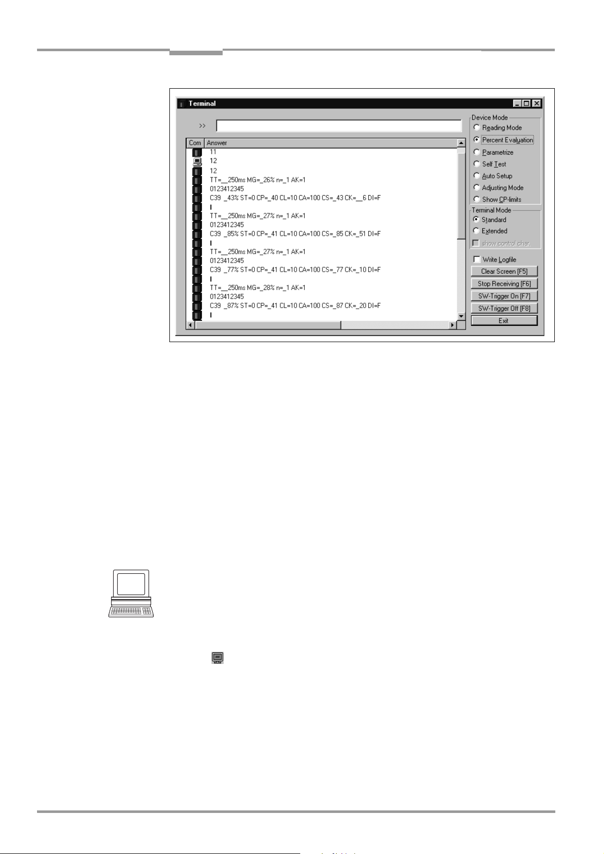
Chapter 6 Operating Instructions
Operation
CLV 42x bar code scanner
Fig. 6-6: CLV Setup: display of the percentage evaluation in the terminal emulator
The output format of the reading result is the same as that of the reading mode. Fig. 6-4,
Page 6-16 explains the structure and function of the reading diagnosis data.
Note Profile bar codes read by the CLV during the percentage evaluation do not cause any
changes to be made to the parameter set and do not, therefore, affect the reading process
either.
The match code cannot be programmed (taught in) in the percentage evaluation mode. This
is entered on the
using the
TEACH-IN method.
DEVICE CONFIGURATION tab. The match code 1 can also be programmed
The CLV outputs the data contents of the uncovered polling reflector with the identifier
"REPO" in the percentage evaluation mode.
6.5.3 Adjusting mode
The Adjusting mode enables the center of the scan line to be optimally positioned on the
bar code.
Chapter 4.3.3 Auxiliary functions for adjustment, Page 4-8 describes the
procedure for going about this after the Adjusting mode has been called up. The CLV does
not output a reading result in this mode.
The Adjusting mode can be called up by choosing VIEW in the menu bar, as a DEVICE FUNCTION
via
CLV 42X (interactively) or via the terminal emulator.
1. Click in the toolbar.
The terminal emulator window is then displayed. The CLV is in reading mode.
2. Click ADJUSTING MODE under DEVICE MODE.
The "Device Ready" LED is extinguished. The CLV cancels the reading mode and masks
the scan line from position CP
= 50 to position CP = 100.
3. Choose READING MODE to exit the Adjusting mode.
The CLV returns to reading mode. The "Device Ready" LED lights up.
6-18 © SICK AG · Division Auto Ident · Germany · All rights reserved 8 009 981/O078/16-08-2004
Page 69
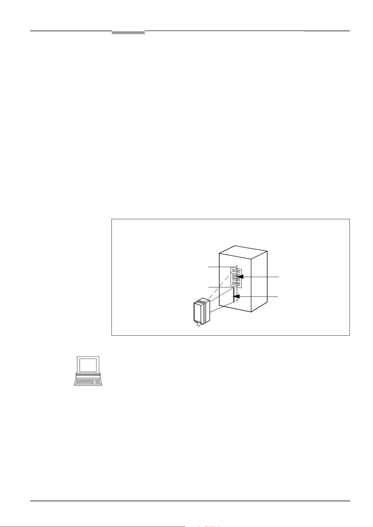
Operating Instructions Chapter 6
CLV 42x bar code scanner
Operation
6.5.4 Show CP-limits
In this mode, the CLV masks certain parts of the scan line so that any limit values defined
for the active evaluation range of the scan line can be checked directly during
parameterization. The restricted active evaluation range shortens the evaluation time for
fast applications, for example, because the evaluation routine needs only take account of
unmasked parts of the scan line. The range is restricted by entering appropriate values for
MINIMUM CODE POSITION and MAXIMUM CODE POSITION in the CODE POSITION section on the
READING CONFIGURATION tab or under DYNAMIC READING CONFIGURATION. The CLV does not
output a reading result.
SHOW CP-LIMITS can be called up via CLV 42X, DEVICE FUNCTIONS (interactively).
The CLV masks the scan line alternately from the set value for CP
for CP
. An example is shown in Fig. 6-11. The switchover is made continuously at
max
and from the set value
min
intervals of one second. The part of the scan line that remains active for the reading
procedure is the section between CP
and CP
min
max
.
Example:
Default setting: Evaluation set for the area from CP
The CLV masks the line from CP
= 5 (short scan line) and from CP
min
= 5 to CP
min
max
= 95.
= 95 (long scan
max
line).
"Show CP-limits"
CP
max
Active area
CP
min
Fig. 6-7: Appearance of scan line in the "Show CP-limits" mode
Scan line 2
Scan line 1
Proceed as follows to check the restricted evaluation range:
1. In the menu bar, choose SHOW CP-LIMITS under CLV 42X, DEVICE FUNCTIONS.
The "Device Ready" LED is extinguished. The CLV cancels reading mode and masks the
scan line alternately (as described above) from CP
and CP
min
max
.
2. Check whether the bar code is located centrally in the area between the end of the
shorter scan line (CP
) and the end of the longer scan line (CP
min
) or, if there are
max
several bar codes, to determine whether the center of the field of all the codes is within
range.
3. If necessary, correct CP
and CP
min
accordingly. Perform a download to the CLV!
max
4. In the menu bar, choose READING MODE under VIEW to exit the SHOW CP-LIMITS mode.
The CLV returns to READING mode. The "Device Ready" LED lights up.
Note In the reading mode, the CLV does not actually mask the scan line visually, but instead takes
the values specified for the restricted evaluation range into account when the data contents
are decoded.
8 009 981/O078/16-08-2004 © SICK AG · Division Auto Ident · Germany · All rights reserved 6-19
Page 70
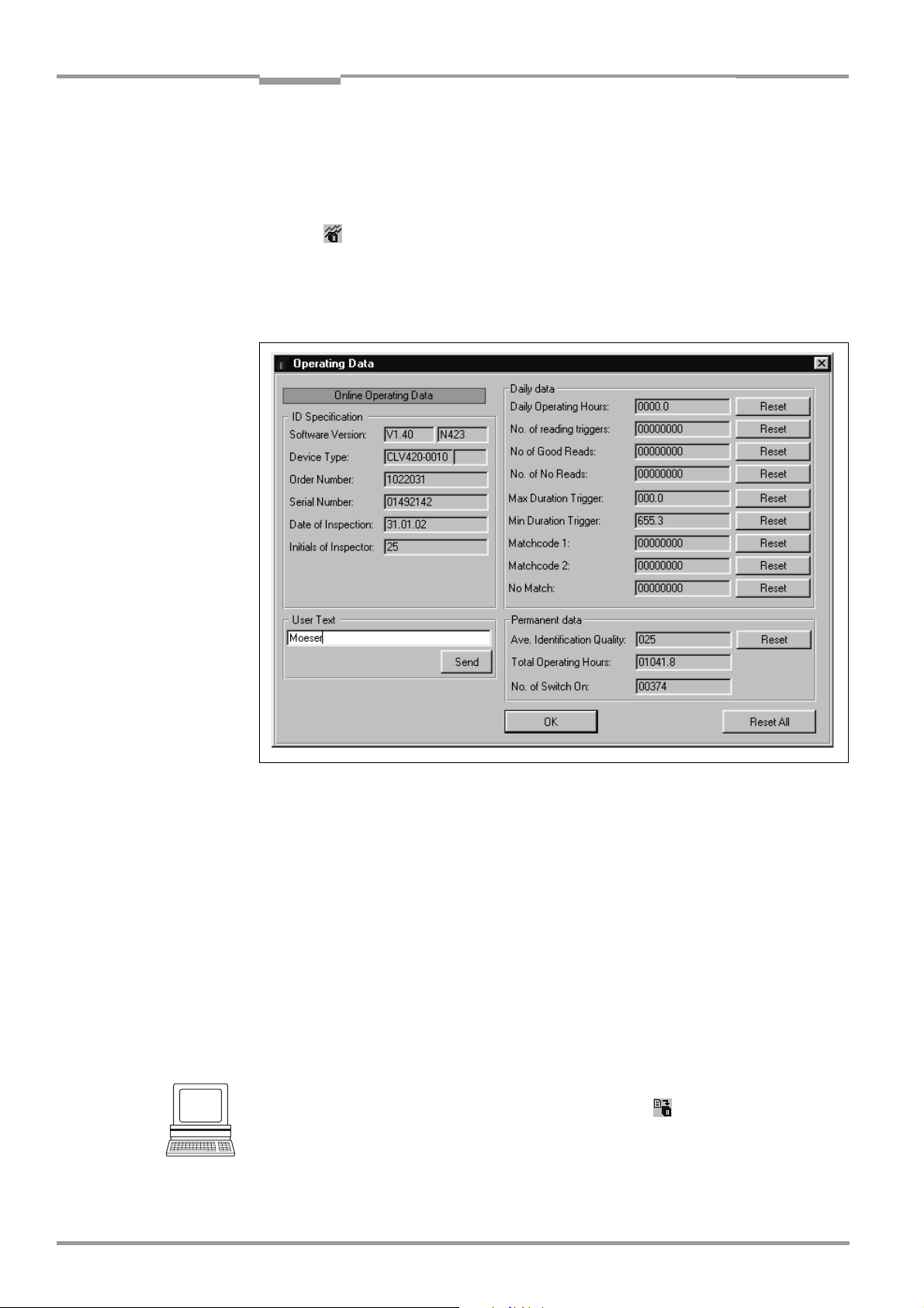
Chapter 6 Operating Instructions
Operation
CLV 42x bar code scanner
6.5.5 Displaying and editing operating data
This function enables statistical operating data, which the CLV maintains in the form of
counters during the reading procedure, to be displayed and reset.
The CLV does not output a reading result in this mode.
1. Click in the toolbar.
The CLV cancels reading mode. The "Device Ready" LED is extinguished.
The OPERATING DATA dialog box appears (Fig. 6-8).
2. After checking/resetting the desired counters, click "OK" to confirm any changes made.
The CLV returns to
reading mode. The "Device Ready" LED lights up.
Fig. 6-8: CLV Setup: "Operating Data" dialog box
6.5.6 Reading diagnosis
Function of the terminal interface. In this mode, the CLV outputs the data contents of all
the bar codes that were read – including those that, according to the evaluation criteria,
were not read properly and were thus incorrect – together with the associated reading
diagnosis data via the terminal interface. The number of bar codes output can, therefore, be
higher than the number of those that were sent via the host interface in the reading result.
In the default setting, this mode is selected for the terminal interface.
Fig. 6-3, Page 6-15 shows the corresponding output format of the terminal interface.
In the default setting, the CLV does not output any reading diagnosis data via the host
interface.
If the reading diagnosis is to remain inactive, this can be set via the AUXILIARY INTERFACE tab.
1. In the AUXILIARY INTERFACE drop-down list, select READING DIAGNOSIS.
2. Perform a download to the CLV. This is done by clicking in the toolbar.
The DOWNLOAD PARAMETER dialog box is displayed.
3. Confirm the dialog box by selecting the PERMANENT save option.
The terminal interface is now set to the "Reading Diagnosis" mode.
6-20 © SICK AG · Division Auto Ident · Germany · All rights reserved 8 009 981/O078/16-08-2004
Page 71
Operating Instructions Chapter 6
CLV 42x bar code scanner
Operation
6.5.7 Monitor host interface
Function of the terminal interface. In this mode, the CLV outputs the data traffic of its host
interface via the terminal interface. Protocol driver handshakes and protocol-specific data,
such as start and stop characters, are suppressed here
(Table 6-6). Each data string is
displayed on a separate line on the screen.
Direction of data Output format Representation
on screen
CLV receives from host <STX> I data <CR> <LF> <ETX> I data
CLV sends to host <STX> O data <CR> <LF> <ETX> O data
Table 6-6: "Monitor Host Interface" function
"Monitor Host Interface" is activated via the AUXILIARY INTERFACE tab.
1. In the AUXILIARY INTERFACE drop-down list, choose MONITOR HOST INTERFACE.
2. Perform a download to the CLV.
To do so, click the MONITOR HOST INTERFACE option again with the right mouse button and
choose D
OWNLOAD PARAMETER in the context menu.
CLV-Setup copies the parameter to the CLV temporarily.
The terminal interface is then set to the "Monitor Host Interface" until the CLV is
switched off again.
Displaying the data traffic of the host interface in the terminal emulator
The data traffic of the host interface can be displayed in the terminal emulator of CLV Setup.
Fig. 6-9, Page 6-22 shows an example of how the reading result can be output.
1. Choose the serial interface as the external trigger source for the reading pulse (see
Triggering the reading pulse via the terminal emulator, Page 6-16).
2. Click in the toolbar.
The terminal emulator window is then displayed. The CLV is in reading mode.
3. Click the SW-TRIGGER ON button or press [F7].
The red scan line appears.
4. Present the bar code sample from Fig. 6-1, Page 6-3.
5. Click the SW-TRIGGER OFF button or press [F8].
CLV Setup outputs the reading result in the terminal emulator.
Example: „0123412345“.
8 009 981/O078/16-08-2004 © SICK AG · Division Auto Ident · Germany · All rights reserved 6-21
Page 72

Chapter 6 Operating Instructions
Operation
CLV 42x bar code scanner
Fig. 6-9: CLV Setup: output of the reading result of the host interface in the terminal emulator at
the beginning (in this case: O
= Output)
Note Large amounts of data received at high speeds via the host interface and high data transfer
rates may cause the flow of host interface traffic to no longer be completely displayed on
the terminal interface (display "…").
This is caused by the slower data transfer speed of the terminal interface (9,600 bd).
In the default setting, the CLV transmits the following data string via the host interface:
• Good Read: the data content of the bar code(s)
• No Read: the NOREAD string
The “Header“, “Code Info/Separator“, “Splitter“ and “Terminator“ blocks are blank.
Tip
The structure of the data output string of the host interface can be configured via the DATA
S
TRINGS tab:
• Up to 10 elements, consisting of constants (control characters, letters, digits) and/or
reading diagnosis data, can be entered in the “Header“, “Code Info/Separator“ and
“Terminator“ blocks .
• Up to 5 elements, consisting of constants (control characters, letters, digits), can be
entered in the “Splitter“ block.
• The position of the “CodeInfo/Separator“ block can be choosen before or after the
Code.
1. Select the DATA STRINGS tab.
2. Click in the HEADER input field.
The dialog window EDIT PARAMETER: TFH is displayed.
3. Click the desired constants or placeholders for the reading diagnosis data.
The selected elements appear in the text box at the top of the dialog window in the
sequence in which they were selected.
4. Confirm the dialog box with "OK".
5. Repeat this procedure for the “Code Info/Separator“, “Splitter“ and “Terminator“ blocks.
6. Perform a download to the CLV. This is done by clicking in the toolbar.
The DOWNLOAD PARAMETER dialog box is displayed.
6-22 © SICK AG · Division Auto Ident · Germany · All rights reserved 8 009 981/O078/16-08-2004
Page 73
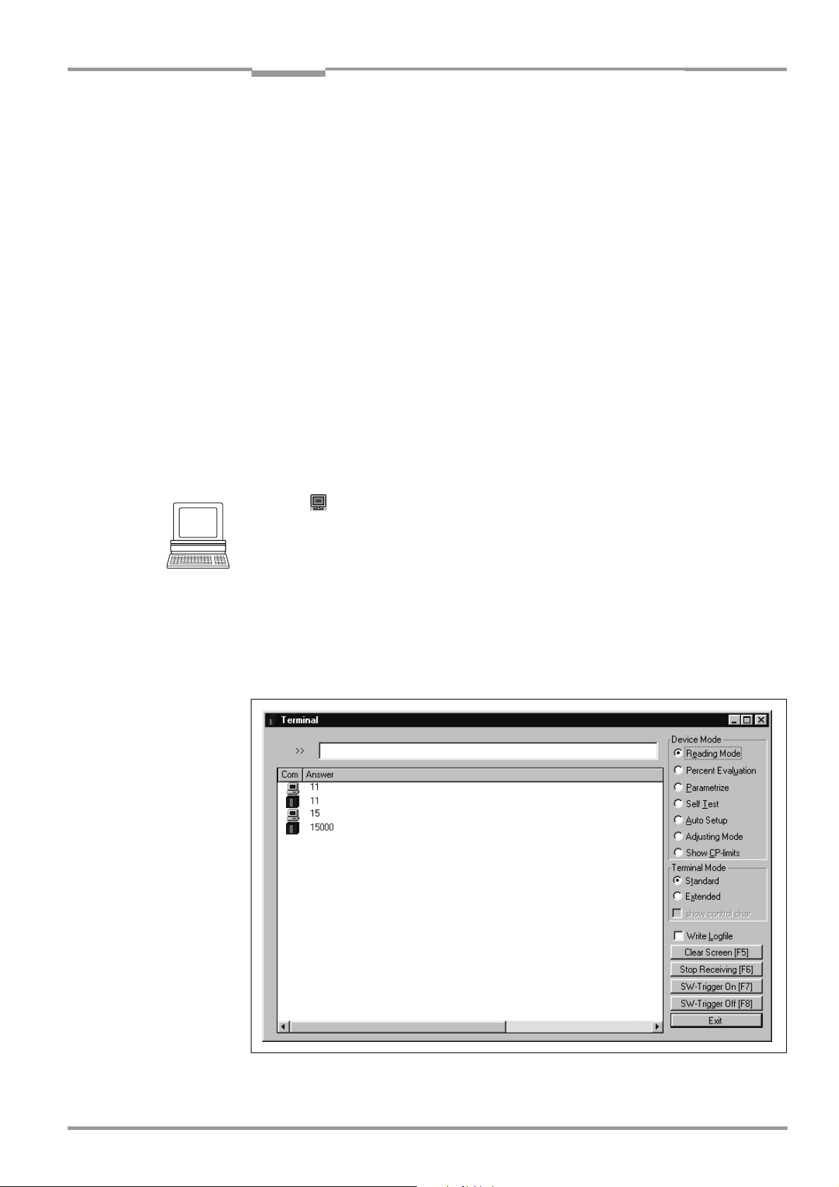
Operating Instructions Chapter 6
CLV 42x bar code scanner
Operation
7. Confirm the dialog box by selecting the PERMANENT save option.
The CLV outputs the selected elements in the data output string of the host interface
with the next reading result.
6.5.8 Auxiliary input
Function of the terminal interface. In this mode, the CLV accepts a bar code entered at the
terminal interface (via the keyboard or hand-held scanner with decoder). It sends the bar
code to the host in a separate data string via its host interface. No reads can, therefore, be
corrected by transmitting missing bar codes subsequently.
Chapter 10.9.2 Auxiliary input via terminal interface, Page 10-31 describes this function and
the associated procedure in greater detail.
6.5.9 Self-test
After the CLV has been switched on, it performs a self-test before it is initialized with the
parameter set. The test can be called up explicitly at any time via CLV Setup. During the selftest, the CLV checks that its hardware components are functioning correctly. A final
message via the terminal interface provides information on the test result. The CLV does not
output a reading result during the test routine.
1. Click in the toolbar.
The terminal emulator window is then displayed.
The CLV is in reading mode.
2. Click SELF TEST under DEVICE MODE.
The "Device Ready" LED is extinguished. The CLV cancels the reading mode and starts
the test routine.
After a few seconds, the CLV outputs the encoded test result in the form of a code
number (
Fig. 6-10).
3. To return to the reading mode, activate READING MODE or close the terminal emulator.
The CLV returns to reading mode. The "Device Ready" LED lights up.
Fig. 6-10: CLV Setup: displaying the self-test result in the terminal emulator
8 009 981/O078/16-08-2004 © SICK AG · Division Auto Ident · Germany · All rights reserved 6-23
Page 74

Chapter 6 Operating Instructions
Operation
CLV 42x bar code scanner
The code number "15000" means that the self-test was completed successfully and that
no faults were diagnosed.
together with the associated corrective measures.
6.5.10 Performing device functions of the CLV in the dialog box
CLV Setup enables a number of CLV functions to be executed interactively. CLV Setup
prompts the user to carry out specific actions and provides information on the progress of
the function being executed.
The following functions are available:
• AutoSetup
• Match code Teach-in
• Show CP-limits
• Adjusting mode
• Analyze scanner network (only if the CAN interface is used)
• Activate factory defaults in device
In the menu bar, select the desired function from CLV 42X, DEVICE FUNCTIONS.
– or –
Press the [F2] key.
The DEVICE FUNCTIONS dialog box is then displayed.
Select the desired function from the EXECUTE menu. CLV Setup starts the function and,
where appropriate, prompts the user to carry out the necessary action.
Fig. 6-11 shows an example of the dialog box that appears after AutoSetup has been
started.
Chapter 8.3 Error messages, Page 8-2, lists the error key
Fig. 6-11: CLV Setup: dialog box for AutoSetup execution
6-24 © SICK AG · Division Auto Ident · Germany · All rights reserved 8 009 981/O078/16-08-2004
Page 75

Operating Instructions Chapter 6
CLV 42x bar code scanner
Operation
6.6 CLV messages
The CLV outputs system messages, warnings and error messages in English in response to
the actions carried out by the user. The messages are output in plain text via the terminal
interface only.
6.6.1 Displaying messages
To display the messages on the PC in the CLV Setup user interface, proceed as follows:
1. Click in the toolbar.
The terminal emulator window is then displayed.
2. In the TERMINAL MODE group, click the EXTENDED radio button.
The CLV then outputs messages in response to events that occur while the bar code is
being read. The messages are only output in the
6.6.2 System messages
System messages confirm that an action has been carried out successfully, e.g. changing
the operating mode. No other actions are required here.
Chapter 10.3 System messages, Page 10-6 explains the contents of the messages.
extended mode of the terminal emulator!
6.6.3 Warnings
Warnings indicate that it was not possible to perform an action or that the values set for the
parameters can cause an error while the bar code is being read.
Message Meaning Remedy
"Warning: Master Timeout" Duration of the set master timeout is too short Optimize the master timeout using the DEVICE
C
ONFIGURATION tab in the user interface of CLV
Setup. Download to the CLV!
(see also technical information "Master/Slave
with CLV Bar Code Scanners", no. 8 007 675,
English version
Table 6-7: Warnings
)
6.6.4 Error messages
Error messages indicate the following error sources:
• a device defect
• incorrect parameter settings
• errors during data transfer to the host
Chapter 8.3 Error messages, Page 8-2 lists the messages in alphabetical order together
with the associated corrective measures.
8 009 981/O078/16-08-2004 © SICK AG · Division Auto Ident · Germany · All rights reserved 6-25
Page 76

Chapter 6 Operating Instructions
Operation
CLV 42x bar code scanner
6.7 Switching off the CLV
1. If the parameter set was modified in CLV Setup or was only stored temporarily in CLV
via a download ("Temporary" option or via context menu (right mouse button)), the
parameter set must be stored permanently in the CLV by choosing the
storage option.
2. Save parameter set as a "*.scl" configuration file in CLV Setup.
3. Switch off the power supply of the CDB 420 or CDM 420 or pull the plug of the CLV
from the connection module.
The last parameter set stored permanently in the CLV remains valid.
We recommend that you print out the configuration file in order to archive the parameter set.
1. Click in the toolbar.
The PRINT FILE dialog box is then displayed.
2. Enter a comment in the input field in order to assign the printout to the CLV.
Confirm the dialog box with "OK".
The PRINT dialog box for configuring the printer is then displayed.
3. Edit the dialog box accordingly and confirm.
CLV Setup prints out the current configuration file in the form of a table.
PERMANENT
6-26 © SICK AG · Division Auto Ident · Germany · All rights reserved 8 009 981/O078/16-08-2004
Page 77

Operating Instructions Chapter 7
CLV 42x bar code scanner
Maintenance
7 Maintenance
7.1 Cleaning during operation
To ensure optimum reading performance, the reading window of the CLV must be clean at
all times.
For this reason, we recommend that you check the reading window at regular intervals,
particularly if the device is operated under extreme conditions (dust, abrasion, humidity,
finger prints).
Laser radiation can seriously damage your eyesight
The CLV uses a class 2 red-light laser. Looking directly at the laser beam can seriously
damage the retina in your eyes.
As with sunlight, never look directly into the laser beam.
Switch off the device while it is being cleaned.
Never look directly into the reading window while the device is in operation.
Damage to the reading window
The reading window is made of glass. Scratches and streaks on the window will reduce the
reading performance.
Use a mild, non-scouring detergent.
Never use scratching or scouring motions to clean the reading window.
Cleaning reading window
Clean the reading window at regular intervals with a mild, non-scouring detergent, e.g.
an antistatic glass cleaning fluid.
Use a soft, lint-free cloth.
If necessary, clean the LEDs on the rear of the device.
Line/Raster scanner
Fig. 7-1 shows the areas that require cleaning.
Line/Raster scanner with
105° angle attachment
clean here:
Fig. 7-1: Cleaning the reading window
Note Don’t open the device. The producer warranty will be forfeited if the device is opened.
8 009 981/O078/16-08-2004 © SICK AG · Division Auto Ident · Germany · All rights reserved 7-1
Page 78

Chapter 7 Operating Instructions
Maintenance
CLV 42x bar code scanner
Cleaning other optical surfaces:
If an external reading pulse generator with a sensor (e. g. photoelectric reflex switch) is
used, make sure to clean the relevant optical surfaces (
these surfaces can cause switching errors.
If the reading pulse is generated by reflector polling, make sure to clean the surface of
the reflector.
Fig. 7-2). Contamination on
Fig. 7-2: Cleaning the external optical sensor (reading pulse generator)
7.2 Maintenance
The CLV does not require any maintenance except the described cleaning measures.
Its self-monitoring function ensures fault-free operation over long periods of time.
Any faults or malfunctions are displayed as error messages via the terminal interface. If they
are plain text, they can be displayed on the PC screen in the extended mode of the Terminal
Emulator in the CLV Setup program. Additional errors are displayed as number combinations
in the fourth field from the left on the bottom, in the status line (
messages, Page 8-2).
see Chapter 8.3 Error
7.3 Disposal
Irreparable devices or devices that are no longer required are to be disposed of in an
environmentally-friendly manner:
1. Always observe the applicable national waste disposal regulations.
2. Remove the CLV housing.
3. Remove the electronic modules and the connection cable.
4. Remove the glass panel from the reading window and send it to be recycled.
5. Send the chassis and cover (zinc die-cast) to be recycled.
6. Send the electronic modules and connection cable for disposal as special waste.
At present, SICK AG does not accept any unusable or irreparable devices.
7-2 © SICK AG · Division Auto Ident · Germany · All rights reserved 8 009 981/O078/16-08-2004
Page 79

Operating Instructions Chapter 8
CLV 42x bar code scanner
Troubleshooting
8 Troubleshooting
8.1 Overview of errors and malfunctions which could occur
8.1.1 Installation errors
• CLV aligned incorrectly with the object carrying the bar code (e. g. masking)
• Reading pulse sensor positioned incorrectly
8.1.2 Electrical connection errors
• Interfaces on the CLV connected incorrectly (wiring error in CDB 420 or CDM 420)
8.1.3 Parameterization errors
• Functions not adjusted to local conditions, e. g. communication parameters on the host
interface are set incorrectly
• Technical limits of the device exceeded, e. g. relationship between the scanning
frequency and the reading distance
8.1.4 Malfunctions during operation
• Laser timeout for laser diode elapsed
• Device error (hardware/software)
8.2 Monitoring errors and malfunctions
The CLV is self-monitoring:
• After the power supply has been switched on, the CLV automatically carries out a selftest, in which it checks important hardware components, before it is initialized (loading
of parameter set and initializing of device functions). The self-test can be repeated at
any time by canceling reading mode. For calling up, see
Page 6-23.
• If the CLV detects an error during the self-test or at any other time, it outputs the error
status ST=3 via the host interface. Prerequisite: the error status is enabled for
transmission. By default, transfer is blocked.
The CLV displays the diagnosed error as a numeric combination in the fourth field from
the left on the bottom, in the status line of CLV Setup (
• While it is in operation, the CLV constantly monitors the laser diode and speed of the
polygon mirror wheel. In addition, a watchdog circuit responds to error statuses.
• A timer automatically deactivates the laser diode 10 minutes (default setting) after a
continuous reading pulse is initiated in reading mode with switching input pulse modes
"Sensor Input" and "Serial Interface". In this case, the CLV outputs the message: "
safety timeout
laser diode is activated again by the next reading pulse.
". The reading pulse must be terminated by resetting the pulse signal. The
Chapter 6.5.9 Self-test,
Table 8-1).
Laser
8 009 981/O078/16-08-2004 © SICK AG · Division Auto Ident · Germany · All rights reserved 8-1
Page 80
Chapter 8 Operating Instructions
Troubleshooting
CLV 42x bar code scanner
8.3 Error messages
The CLV outputs error messages in plain text (English) on the terminal interface only.
Additional errors are displayed as number combinations in the status line of CLV Setup.
Table 8-1 contains a list of the messages in alphabetical order.
For warnings, see Chapter 6.6.3 Warnings, Page 6-25
Displaying messages:
To display the messages on the PC in the CLV Setup user interface, proceed as follows:
1. Click in the toolbar.
The Terminal Emulator window is then displayed.
2. In the TERMINAL MODE group, activate the EXTENDED radio button.
Message Meaning Possible cause Remedy
"CLV SYS-Failure: xxx"
011 RAM error
012 RAM error
013 RAM error
051 Mirror wheel speed
out of tolerance
061 Mirror interval out of
tolerance
071 Error: laser shutter
"EEPROM Check fault,
default parameters loaded"
"EEPROM - reading fault" The CLV cannot download the
"EEPROM - writing fault" The CLV cannot write the
"Host – receive fault" The host has requested the
"Host – transfer too slow" In the CLV, data is available
The CLV has diagnosed a
system error. The "Device
Ready" LED does not light up
or it extinguishes. The CLV
restarts the system.
The CLV has diagnosed an
irregularity in the EEPROM
and downloads the entire
default settings to the RAM
instead of the permanently
stored application-specific
parameters.
application-specific parame
ters, permanently stored in
the EEPROM, to the RAM.
current parameters in the
RAM to the EEPROM.
data output string last sent by
the CLV three times; NAK has
been issued with each
attempt.
for output faster than it is
transmitted to the host.
-
Device fault If this system error occurs again
after the CLV is restarted:
Contact the SICK Service
department.
Device fault Contact the SICK Service
department.
Device fault Contact the SICK Service
department.
Device fault Contact the SICK Service
department.
• Host receive set incorrectly
• Data transmission interrupted
e.g. by cable break
• Baud rate too low
• Incorrect protocol type
selected
• Protocol timeout too long for
the reading pulse frequency
• Check host.
• Check connecting cables and
monitor data transmission at
the host interface. To do so,
upload from the CLV using the
CLV Setup program, choose
AUXILIARY INTERFACE tab and
the
select
MONITOR HOST INTERFACE
from the drop-down list.
Download to the CLV! Start the
Terminal Emulator.
Check the configuration of the
host interface.
Table 8-1: Error message output on the terminal interface
8-2 © SICK AG · Division Auto Ident · Germany · All rights reserved 8 009 981/O078/16-08-2004
Page 81

Operating Instructions Chapter 8
CLV 42x bar code scanner
Message Meaning Possible cause Remedy
"Host – transmit fault" The CLV cannot correctly
"More than one code found" AutoSetup was not
"No valid code found"
Troubleshooting
receive the data sent by the
host.
successful.
AutoSetup was not
successful.
• Host interface of the CLV
configured incorrectly
• Data transmission interrupted
e. g. by cable break
More than one bar code was
presented to the CLV
No bar code was presented to
the CLV or the reading quality did
not reach 75%
• Check the CLV and host.
• Check connecting cables and
monitor data transmission at
the host interface. To do so,
upload from the CLV using the
CLV Setup program, choose
AUXILIARY INTERFACE tab and
the
MONITOR HOST INTERFACE
select
from the drop-down list.
Download to the CLV! Start the
Terminal Emulator.
Repeat AutoSetup.
Make sure that only one bar code
is located within the visible range
of the CLV!
Repeat AutoSetup.
Make sure that the bar code is
located within the reading range
of the CLV.
Table 8-1: Error message output on the terminal interface (contd.)
8 009 981/O078/16-08-2004 © SICK AG · Division Auto Ident · Germany · All rights reserved 8-3
Page 82

Chapter 8 Operating Instructions
Troubleshooting
CLV 42x bar code scanner
8.4 Error status ST in read result of a bar code
Value Meaning Possible cause Remedy
0 "Good read" – not applicable
1 Incorrect check digit The check digit calculated by the CLV
during the reading process does not
match that printed in the bar code.
2 No bar code of the enabled code type
found according to the evaluation
criteria
3 Device fault Device fault Call up the self-test! See
5 Required number of successful
multiple reads for the bar code not
reached
6 Master:
Number of slave reading results does
not match the parameterized number
of slaves
7 The source of the reading result is the
auxiliary input via the terminal
interface
9 The OUTPUT FILTER function is also
activated for the code comparison.
The CLV has detected valid bar codes.
However, these do not match the
active match code(s)
A The CHECK MAX. NUMBER OF CODES
function is active.
The number of valid bar codes
detected by the CLV in reading mode
exceeds that specified under NUMBER
OF CODES: MAXIMUM.
It repeatedly outputs the defined error
string until the number specified under
NUMBER OF CODES: MINIMUM is reached.
D The "Code 32" evaluation option is
activated for Code 39.
The CLV is attempting to interpret
6-digit C39 bar codes as C32 bar
codes (output as 9-digit decimal
values).
• No bar code in the CLV's reading range
during the reading pulse
• Code type/length in the CLV not
enabled for decoding
• Reading window obstructed/dirty
• Conveyor speed of the object is too
high
• Scanning frequency is too low
• Ladder-type arrangement for bar code
relative to the conveyor direction: code
height (bar length) too poor
• Print quality too poor
• The parameterized number of slaves
does not match the actual number of
slaves available.
• Timeout for the master is selected too
short.
• Data connection between slaves and/
or the master has been interrupted.
The bar code was not detected by the
reading function of the CLV, but was
entered subsequently with the auxiliary
function of the terminal interface and sent
to the host in a separate data string.
The scanned object does not have a bar
code that matches the specified match
code.
One object in a set of objects with a
constant number of bar codes, for
example, contains more bar codes than
defined in the application.
The read 6-digit bar code is not a C32 bar
code. The CLV outputs the defined error
string instead.
Check whether the check digits in the
bar code which were generated by
the print process are correct.
• Synchronize the pulse of the CLV
with the entry of a bar code into the
reading area.
• Correct the code configuration
parameters.
• Check the reading window.
Chapter 6.5.9 Self-test, Page 6-23.
If result ≠ 000: Contact the SICK
Service department.
• Check the conveyor speed.
• Adjust the scanning frequency.
• Check the code height.
• Check the print quality.
• Check the entered number of
slaves.
• Check the master timeout setting.
• Check the cables between the
slaves and the master.
not applicable
not applicable
This message is used to indicate
errors on the objects (e.g. check
whether objects are homogeneous:
mix with incorrect objects).
not applicable
Table 8-2: Meaning of the ST error status in the reading result
8-4 © SICK AG · Division Auto Ident · Germany · All rights reserved 8 009 981/O078/16-08-2004
Page 83
Operating Instructions Chapter 8
CLV 42x bar code scanner
Value Meaning Possible cause Remedy
F The CHECK MIN. NUMBER OF CODES
function is active.
The number of valid codes detected
by the CLV in Reading mode is less
than that specified under N
ODES: MINIMUM.
C
Instead of the code contents, it
outputs the defined error string in the
quantity defined under N
ODES: MINIMUM
C
Table 8-2: Meaning of the ST error status in the reading result (contd.)
Troubleshooting
One object in a set of objects with a
constant number of codes, for example,
contains fewer codes than defined in the
application.
UMBER OF
UMBER OF
This message is used to indicate
errors on the objects (e. g. check
whether objects are homogeneous:
mix with incorrect objects).
8.5 Troubleshooting
The following are required for troubleshooting purposes using the tables
below:
• These Operating Instructions
• Tools
• A tape measure (up to 1 m (39.4 in))
• A digital measuring device (ammeter/voltmeter)
• A PC running "CLV Setup"
• A 3-core RS 232 data cable (null modem cable), pins 2 and 3 crossed,
e. g. no. 2 014 054
8.5.1 General malfunction: CLV not ready
Malfunction Possible cause Remedy
The "Device Ready" LED is not lit.
The "Device Ready" switching output
(default setting: "Good read") is not
outputting a pulse.
Table 8-3: Troubleshooting: restoring operation (reading mode)
After switching on the power supply
(10
to 30 V DC):
• CLV not supplied with operating voltage
• The CLV has diagnosed a device error in
the self-test
During operation:
• The CLV is not in "reading" mode
• The CLV has deactivated the laser diode
10 min (default setting) after the start of
the current reading pulse (pulse mode:
sensor input/serial interface)
• Check wiring (power connector fitted
securely to the CDB 420 or CDM 420
connection module).
Measure voltage at pin 1 and pin 5.
• Switch the CLV off and on again. Does
the LED light up? If not, contact the SICK
Service department.
• Return to reading mode using the
CLV Setup program
See Chapter 6.5.1 Reading mode
(standard operating mode), Page 6-14.
• Terminate reading pulse.
Check the reading pulse function.
Generate new pulse or parameterize
new laser timeout duration using the CLV
Setup user interface. See
Parameterization guide, Page 6-7.
Chapter 6.4.3
8 009 981/O078/16-08-2004 © SICK AG · Division Auto Ident · Germany · All rights reserved 8-5
Page 84

Chapter 8 Operating Instructions
Troubleshooting
CLV 42x bar code scanner
8.5.2 Malfunctions in reading mode: reading pulse errors
Prerequisite The "Device Ready" LED lights up. If not, see Table 8-3, Page 8-5.
Malfunction Possible cause Remedy
1. Pulse mode:
sensor input
(external sensor).
The CLV cannot be pulsed:
– the "Laser On" LED does not light up
– the scan line does not appear
2. Pulse mode:
Reflector polling
The CLV cannot be pulsed:
– the "Laser On" LED flickers but does
not light up constantly
– the scan line is very faint
3. Pulse mode:
Serial Interface
The CLV cannot be pulsed:
– the "Laser On" LED does not light up
– the scan line does not appear
4. CLV does not respond to an external
signal that ends the reading pulse
(sensor input, reflector polling, serial
interface)
• Incorrect reading pulse source
parameterized on the CLV
• Polarity of switching input inverted
• Sensor not connected or connected to
incorrect switching input
• If sensor supplied by CLV: sensor not
connected to ground potential
• Photoelectric switch not aligned with the
reflector (photoelectric switch/inductive
sensor not dampened)
• Incorrect reading distance (polling
reflector)
• Incorrect reflector type used
• Incorrect pulsing sequence (reflector is
not blocked to start the reading interval
on the CLV)
• Incorrect reading pulse source
parameterized on the CLV
• The CLV is not receiving any command
string to start the reading interval on the
data interface
• Incorrect end of reading pulse
parameterized on the CLV
• No sensor signal
• In the CLV Setup program: Select the
DEVICE CONFIGURATION tab and click the
READING TRIGGER PARAMETERS button.
READING TRIGGER SOURCE group: sensor
input selected?
• Active high: reading pulse starts when
power applied
• Connect sensor to "Sensor 1" switching
input.
Check sensor wiring (Fig. 5-4, Page 5-8).
Measure output signal on sensor.
• Insert jumper between pin 5 and pin 15
• Align sensor. Check functioning.
• Check: reading distance of reflector in
specified reading range?
• Check reflector type, Table 4-2,
Page 4-11.
• Check sequence:
Read: 1. Block reflector, 2. Read bar
code, 3. Unblock reflector.
• In the CLV Setup program: Select the
DEVICE CONFIGURATION tab and click the
READING TRIGGER PARAMETERS button.
In the READING TRIGGER SOURCE group: is
serial interface selected?
Group SERIAL INTERFACE: is trigger type
correct?
• Check data connection to host.
In the CLV Setup program: Select the
HOST INTERFACE tab.
In DATA FORMAT group: are the correct
interface type (hardware) and data
format selected?
Group: INTERFACE PROTOCOL: are the
correct start and stop characters
selected?
• Use the CLV Setup program to check the
host command strings: Choose
NTERFACE tab. Choose MONITOR HOST
I
I
NTERFACE function. See Chapter 6.5.7
Monitor host interface, Page 6-21.
Download temporarily to the CLV.
• In the CLV Setup program: Check by
choosing the DEVICE CONFIGURATION tab,
click the
button.
"Generated by Trigger Source"
selected?
• See Malfunction 1, Remedy
READING TRIGGER PARAMETERS
END OF READING INTERVAL group: is
AUXILIARY
Table 8-4: Troubleshooting: reading pulse errors in reading mode
8-6 © SICK AG · Division Auto Ident · Germany · All rights reserved 8 009 981/O078/16-08-2004
Page 85

Operating Instructions Chapter 8
CLV 42x bar code scanner
Troubleshooting
8.5.3 Malfunctions in reading mode: result output errors
Check whether the "Device Ready" LED illuminates.
If the LED does not illuminate, follow Table 8-3, Page 8-5.
For the following, the number of bar codes to be read is 1.
Malfunction Possible cause Remedy
1. The "Result" LED
(default setting: "Good read") does not
light up at the end of the reading pulse.
– The "Result 2" switching output
(default setting: "Good read") is
not outputting a pulse
– The CLV outputs the status ST = 2
in the reading result on the host
interface (if ST is enabled for the
separator; this is not selected in
the default setting)
• Read not successful, since there was no
bar code in the reading field during the
reading pulse
• Scan line positioned incorrectly
• Evaluation range of the scan line is
limited improperly (CP
• Bar code presented at incorrect reading
distance
• The bar code is tilted excessively with
respect to the scan line
• The reading angles at which the bar code
appears to the CLV are too large
• Bar code is in total reflection zone
values)
• Synchronize reading with an object in the
reading field.
See Chapter 8.5.2 Malfunctions in
reading mode: reading pulse errors,
Page 8-6.
• Align CLV.
Is bar code at center of scan line?
In the CLV Setup program: check reading
quality. Choose
See Chapter 6.5.2 Percentage evalua-
tion, Page 6-17.
• In the CLV Setup program: Check by
choosing the
CODE POSITION group: are the min. and
max. code position values correct?
Check with
See Chapter 6.5.4 Show CP-limits,
Page 6-19.
• Check: reading distance of bar code in
specified reading range?
• Align bar code accordingly.
• In the CLV Setup program: Start
PERCENTAGE EVALUATION, select DISTANCE
C
ONFIGURATION (if used).
Monitor reading quality (reading quality
>70 %!).
Realign CLV if necessary.
• Optimize CLV alignment (scan line should
strike the bar code at an skew of approx.
15°).
In the CLV Setup program: check reading
quality. Start
Chapter 6.5.2 Percentage evaluation,
Page 6-17.
PERCENTAGE EVALUATION.
READING CONFIGURATION tab,
SHOW CP-LIMITS.
PERCENTAGE EVALUATION. See
Table 8-5: Troubleshooting: result output errors in reading mode
8 009 981/O078/16-08-2004 © SICK AG · Division Auto Ident · Germany · All rights reserved 8-7
Page 86

Chapter 8 Operating Instructions
Malfunction Possible cause Remedy
1. The "Result" LED does not light up at
the end of the reading pulse.
(default setting: "Good read")
– continued –
2. The CLV is not transferring any reading
results to the host.
3. The CLV transfers the status ST = 3 to
the host in the reading result
(if ST is enabled for the separator; this
is not selected by default).
4. The data content of the bar code
output by the CLV is incorrect or
incomplete.
Troubleshooting
• Evaluation criteria for bar code incorrect
• Bar code quality not adequate
• Reading pulse is not functioning correctly
• Wiring fault in data connection
• Voltage level incorrect
• Host interface in CLV parameterized
incorrectly
The CLV has diagnosed a device error in
the self-test.
• The data format on the host interface is
parameterized incorrectly in the CLV
• The CLV suppresses the last character in
the bar code.
CLV 42x bar code scanner
• In the CLV Setup program: Choose the
CODE CONFIGURATION tab, SYMBOLOGIES
group.
Enable all code types (except
Pharmacode), set code lengths to
Download temporarily to CLV!
Start PERCENTAGE EVALUATION. Code type
and length are displayed in the reading
result.
Enable recorded code type in the
SYMBOLOGIES group and disable all other
types. Enter the code length under
on the code type tab. Download to CLV!
• Check: Are sufficient blank zones
present?
Is the print contrast adequate?
Are the specified print tolerances
exceeded?
In the CLV Setup program: Check by
choosing
QUIET ZONE group. Is "Start/Stop"
selected?
Perform test read with a reference code
in good condition.
• See Chapter 8.5.2 Malfunctions in
reading mode: reading pulse errors,
Page 8-6.
• Check wiring as shown in Fig. 5-2,
Page 5-5.
• Measure voltages.
• In the CLV Setup program:
Check by choosing HOST INTERFACE tab,
DATA FORMAT group.
Are the correct interface type (hardware)
and data format selected?
Check settings in INTERFACE PROTOCOL
group.
Switch the CLV off and on again. Does the
"Device Ready" LED light up? If not, contact
the SICK Service department.
• In the CLV Setup program: Select the
HOST INTERFACE tab, DATA FORMAT group.
Are the values correct?
• In the CLV Setup program: Select the
CODE CONFIGURATION tab. Click the
SYMBOLOGY PARAMETERS button.
Choose the tab for the relevant code.
Is Transmit Check Digit activated?
Change if necessary. Download to CLV!
READING CONFIGURATION tab,
FREE.
FIXED
Table 8-5: Troubleshooting: result output errors in reading mode (contd.)
8-8 © SICK AG · Division Auto Ident · Germany · All rights reserved 8 009 981/O078/16-08-2004
Page 87

Operating Instructions Chapter 8
CLV 42x bar code scanner
Troubleshooting
8.5.4 Malfunctions in reading mode: errors when outputting the result status
Prerequisite The "Device Ready" LED lights up. If not, see Table 8-3, Page 8-5.
Malfunction Possible cause Remedy
1. The "Result 1" (default setting:
"Device Ready") and "Result 2"
(default setting: "Good read")
switching outputs are not outputting
any pulses.
2. The beeper is not confirming the
output of the reading result (default
setting: "Good read").
Table 8-6: Troubleshooting: errors in the result status output in reading mode
• The event of the assigned function for
outputting the result status does not
occur during the reading process
• Incorrect switching mode parameterized
in CLV
Beeper deactivated In the CLV Setup program: Check: Check by
• not applicable
• In the CLV Setup program: Check by
choosing the
Click the
button. Are the outputs set to
Output"
Change if necessary. Download to CLV!
choosing
BEEPER VOLUME: is "Low" or "High"
selected?
DEVICE CONFIGURATION tab.
RESULT OUTPUT PARAMETERS
"Invert
?
DEVICE CONFIGURATION tab, group
8.5.5 Malfunctions: configuration errors (parameterization)
Prerequisite The "Device Ready" LED lights up. If not, see Table 8-3, Page 8-5.
Malfunction Possible cause Remedy
1. AutoSetup:
The CLV does not read the presented,
application-specific bar code (no
confirmation from beeper)
2. Profile programming:
CLV does not read the presented
profile bar code (no confirmation from
beeper)
• CLV not in "AutoSetup" mode
• If AutoSetup is started with profile bar
code no. 10: wait time of 5 s after powerup has been exceeded
• Bar code presented at incorrect reading
distance
• Bar code is in total reflection zone
• Bar code quality not adequate
• Wait time of 5 s after power-up has been
exceeded
• Wait time of 10 s after the first profile bar
code was presented has been exceeded
• In reading mode: CLV not pulsed
• Check: Does the "Device Ready" LED
light up? If so, the CLV is in "reading"
mode again.
In CLV Setup program: Restart
A
UTOSETUP from the VIEW pull-down
menu.
• Switch the CLV off and on again.
Present profile bar code no. 10 within
5 s.
Then present the application-specific bar
code.
• Check: Is the reading distance of the bar
code within the specified reading area?
• Optimize bar code alignment (scan line
should strike the bar code at an angle of
approx. 15°).
• See Malfunction 1, Table 8-5, Page 8-7
• Switch the CLV off and on again.
Present profile bar code within 5 s.
• Once the first profile bar code has been
read successfully, present the next bar
code within 10 s, etc.
• Clock the CLV accordingly and present
the first profile bar code. Present the next
bar code within 10 s, etc.
Table 8-7: Troubleshooting: configuration errors (parameterization)
8 009 981/O078/16-08-2004 © SICK AG · Division Auto Ident · Germany · All rights reserved 8-9
Page 88

Chapter 8 Operating Instructions
Troubleshooting
CLV 42x bar code scanner
8.6 SICK Support
If a system error occurs repeatedly ("CLV SYS-Failure: xxx", xxx = 000 to 071) or if you
cannot correct an error using the above measures, the CLV may be defective. The CLV
contains no user-serviceable parts.
Please contact our local SICK office or subsidary:
• The telephone numbers and email addresses are listed on the back page of this
manual.
For addresses see also www.sick.com.
Do not send the device to the SICK service without first contacting us.
8-10 © SICK AG · Division Auto Ident · Germany · All rights reserved 8 009 981/O078/16-08-2004
Page 89
Operating Instructions Chapter 9
CLV 42x bar code scanner
Technical data
9 Technical data
9.1 Data sheet CLV 420/421/422 bar code scanners (fixed focus)
Type CLV 420 (Standard) CLV 421 (Long Range) CLV 422 (High Density)
Line scanner CLV 420-0010 CLV 421-0010 CLV 422-0010
Raster scanner CLV 420-1010 CLV 421-1010 CLV 422-1010
Line scanner with 105° angle attachment CLV 420-2010 CLV 421-2010 CLV 422-2010
Raster scanner with 105° angle attachment CLV 420-3010 CLV 421-3010 CLV 422-3010
Focus Fixed focus
Reading window Line/raster scanner: front
Line/Raster scanner with angle attachment: side (angle of emergence 105°)
Laser diode (wavelength) red light (λ = 650 to 670 nm)
MTBF of laser diode 20,000 h
Laser class of device
Useable aperture angle max. 50°
Scanning/decoding frequency 400 to 1,200 Hz
Resolution 0.2 to 1.0 mm
Reading areas See reading field diagrams, Chapter 10.2 Specification diagrams, Page 10-1
Trigger source for switching over the
reading configuration
Raster height 15 mm (0.6 in) (8 lines) at a reading distance of 200 mm (7.9 in) (front reading window)
Bar code print contrast (PCS) ≥ 60 %
Immunity to ambient light 2,000 lx (on bar code)
No. of bar codes per scan 1 to 3
No. of bar codes per reading interval
Bar code types Code 39, Code 128, Code 93, Codabar, EAN, EAN 128, UPC, 2/5 Interleaved,
Bar code length max. 50 characters (max. 100 characters across all bar codes per reading interval)
Print ratio 2:1 to 3:1
No. of multiple reads 1 to 99
Visual indicators 4 x LEDs
Acoustic indicator Beeper, can be deactivated and assigned to a function for result status indication
Reading pulse Reflector polling/"Sensor 1" switching input/free running/Continuous Read/
"Host" data interface RS 232 or RS 422/485, variable data output format
Data transfer rate 300 to 57,600 bd
Protocols SICK Standard, 3964(R)
Physical configurations Standalone
"CAN" data interface CANopen protocol, CAN Scanner Network
Data transfer rate 20 kbps to 1 Mbps
1) in Reading mode with the "Switching input Sensor 1" and "Serial interface" pulse types
2) Reading interval: time window generated internally for evaluating the code
2)
Class 2 (pursuant to DIN EN 60825-1), shutoff of laser diode after 10 min
0.35 to 1.0 mm
(7.8 to 39.4 mil)
"Sensor 2" switching input/serial interface/timer
1 to 10 (autodiscriminating)
Pharmacode
serial interface
(13.8 to 39.4 mil)
0.15 to 0.5 mm
(5.9 to 19.7 mil)
1)
Table 9-1: Technical specifications of the CLV 420/421/422 (line/raster scanner)
8 009 981/O078/16-08-2004 © SICK AG · Division Auto Ident · Germany · All rights reserved 9-1
Page 90

Chapter 9 Operating Instructions
Technical data
CLV 42x bar code scanner
Type CLV 420 (Standard) CLV 421 (Long Range) CLV 422 (High Density)
"Terminal" data interface RS 232; 9,600 bd; 8 data bits; no parity; 1 stop bit; fixed output format
Switching inputs 2 ("Sensor 1", "Sensor 2")
– optodecoupled, V
= 28V, non-interchangeable, can be connected to PNP outputs
imax
– "Sensor 1" (reading pulse): max. internal delay 30 ms (standard)/
selectable: reduced max 0.6 ms or 10 ms to 100 s (user defined)
– "Sensor 2" (variable function): max. internal delay 30 ms
Switching outputs 2 ("Result 1", "Result 2")
– PNP, I
= 100 mA, short-circuit-proof, variable pulse duration (stat., 10 to 990 ms)
omax
– Variable output function for result status
Electrical connection 15-pin D Sub HD connector, cable length 0.9 m (35.5 in)
Operating voltage3)/power consumption 10 to 30 V DC pursuant to IEC 364-4-41 (VDE 0100 (Teil 410))/3.5 W
Housing Zinc die-cast, does not represent a problem in paint shops
Enclosure rating/Protection class IP 65 (to DIN 40 050)/Class 3 (to VDE 0106/IEC 1010-1)
EMC/vibration/shock tested persuant to EN 61000-6-2, EN 55011/persuant to IEC 68-2-6 Test FC/pursuant to
IEC 68-2-27 Test EA
Wei ght 250 g (8.8 oz) with connecting cable
(with side 105° angle attachment : approx. 320 g (11.3 oz))
Operating/storage temperature 0 to +40 °C/–20 to +70 °C (+32 to 104 °F/–4 to + 158 °F)
Max. rel. humidity 90 %, non condensing
Color SICK blue (RAL 5012)
3) The CLV 42x is UL certificated when a class 2 power supply according to UL 1310 is used.
Table 9-1: Technical specifications of the CLV 420/421/422 (line/raster scanner) (contd.)
9-2 © SICK AG · Division Auto Ident · Germany · All rights reserved 8 009 981/O078/16-08-2004
Page 91

Operating Instructions Chapter 9
CLV 42x bar code scanner
Technical data
9.2 CLV dimensional drawings
Line/Raster scanner with front light emergence:
Line/Raster scanner with side light emergence:
All specifications in mm (in)
Fig. 9-1: Dimensions of the CLV 42x line/raster scanner
8 009 981/O078/16-08-2004 © SICK AG · Division Auto Ident · Germany · All rights reserved 9-3
Page 92

Chapter 9 Operating Instructions
Notes
Technical data
CLV 42x bar code scanner
9-4 © SICK AG · Division Auto Ident · Germany · All rights reserved 8 009 981/O078/16-08-2004
Page 93

Operating Instructions Chapter 10
CLV 42x bar code scanner
Appendix
10 Appendix
10.1 Overview
The Appendix contains the following additional information:
• Specification diagrams
– Line/Raster scanner
– Line/Raster scanner with 105° angle attachment
• System messages
• Installation and operating instructions for the PC-based "CLV Setup" program
• Configuring the CLV with profile bar codes
• Configuring the CLV with commands
• Calculating parameter values for setting the CLV
• Tables
• Special applications and procedures
• Replacing a CLV (copying the parameter set)
• Accessories
• Dimensional drawings of the accessories
• Supplementary documentation
• Glossary
• Copy of the EC Declaration of Conformity
• Index
• Scannable sample bar codes
10.2 Specification diagrams
10.2.1 Reading conditions for all diagrams
Test code Code 39/ITF
Print ratio 2:1
Print contrast > 90 %
Tilt
Ambient light < 2000 lx
Good read rate > 75 %
Table 10-1: Reading conditions for specification diagrams
Raster scanner:
raster height 15 mm (0.59 in) at 200 mm (7.88 in) reading distance
Note Line/raster scanner with 105° angle attachment:
the whole reading range shifts by 15 mm (0.59 in) towards the reading window.
For the CLV 420 a corresponding reading field diagram is shown in Fig. 10-2.
±10°
8 009 981/O078/16-08-2004 © SICK AG · Division Auto Ident · Germany · All rights reserved 10-1
Page 94

Chapter 10 Operating Instructions
Appendix
CLV 42x bar code scanner
10.2.2 Reading field diagram for CLV 420 line/raster scanner (front reading window)
General reading conditions:
see Table 10-1, Page 10-1
Scan frequency/reading distance
characteristics:
see Fig. 10-5, Page 10-6
Fig. 10-1: CLV 420-0010/-1010: reading range (DOF) for line/raster scanner
10-2 © SICK AG · Division Auto Ident · Germany · All rights reserved 8 009 981/O078/16-08-2004
Page 95

Operating Instructions Chapter 10
CLV 42x bar code scanner
Appendix
10.2.3 Reading field diagram for CLV 420 line/raster scanner with 105° angle attachment (lateral reading window)
General reading conditions:
see Table 10-1, Page 10-1
Scan frequency/reading distance
characteristics:
see Fig. 10-5, Page 10-6
Fig. 10-2: CLV 420-2010/3010: reading range (DOF) for line/raster scanner with 105° angle attachment
8 009 981/O078/16-08-2004 © SICK AG · Division Auto Ident · Germany · All rights reserved 10-3
Page 96
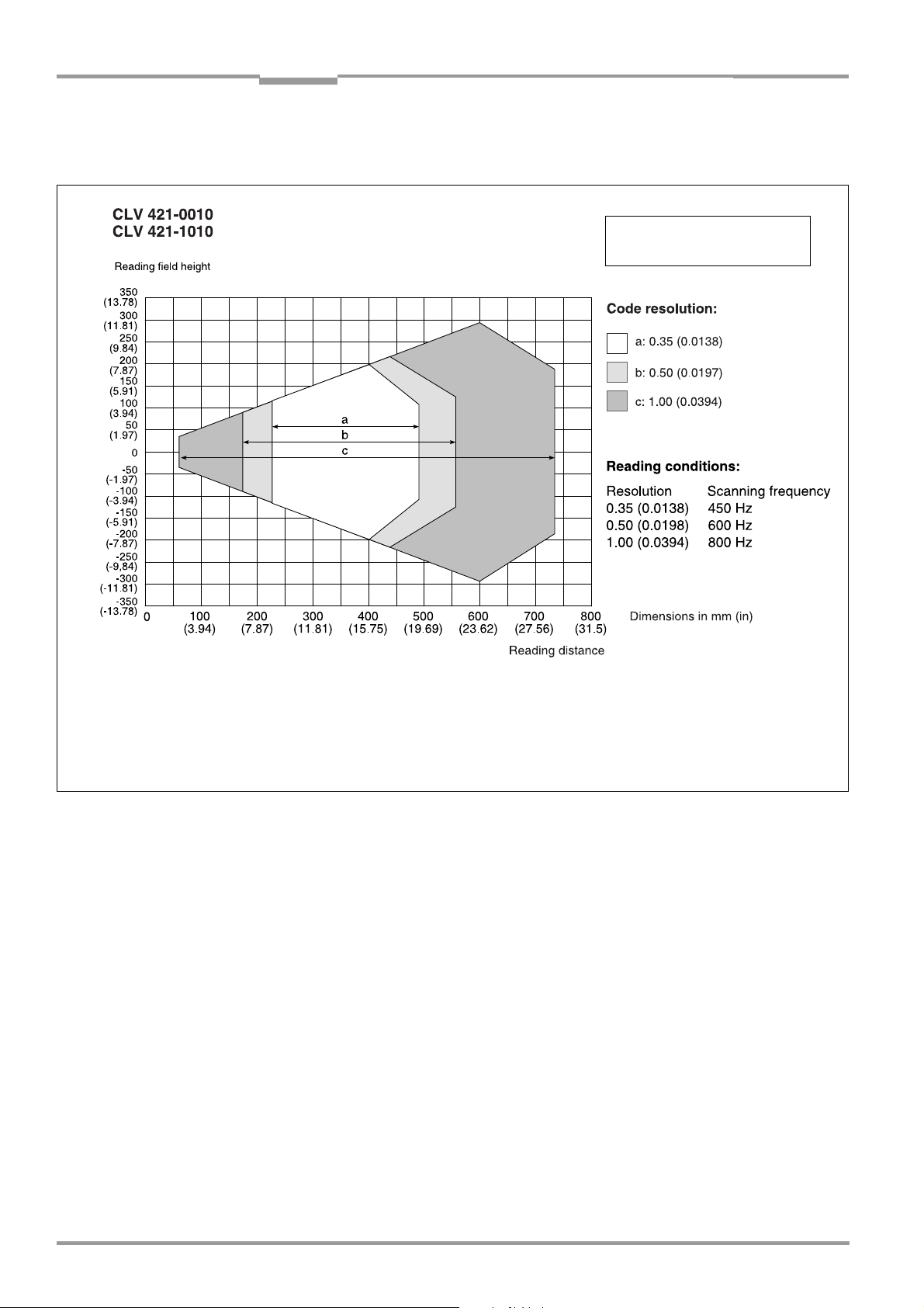
Chapter 10 Operating Instructions
Appendix
CLV 42x bar code scanner
10.2.4 Reading field diagram for CLV 421 line/raster scanner (front reading window)
General reading conditions:
see Table 10-1, Page 10-1
Scan frequency/reading distance
characteristics:
see Fig. 10-5, Page 10-6
Fig. 10-3: CLV 421-0010/1010: reading range (DOF) for line/raster scanner
10-4 © SICK AG · Division Auto Ident · Germany · All rights reserved 8 009 981/O078/16-08-2004
Page 97
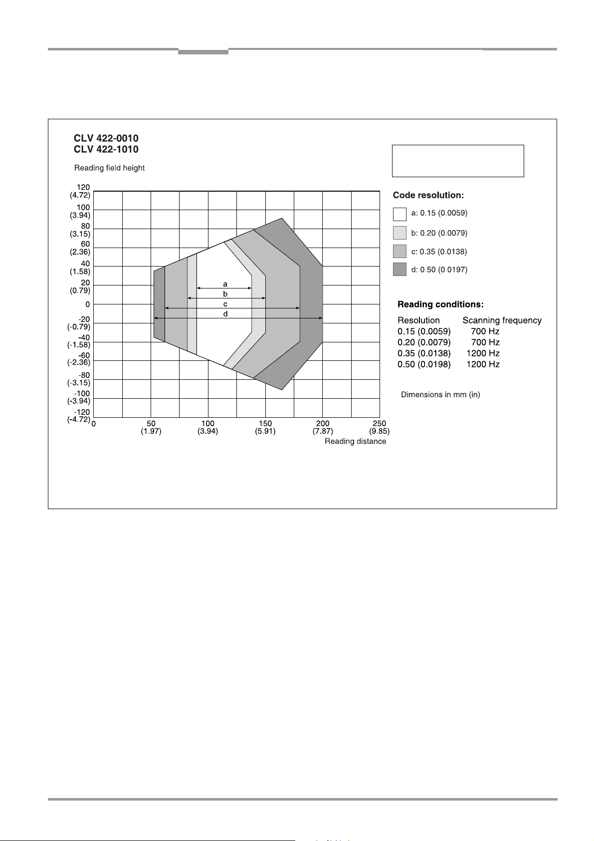
Operating Instructions Chapter 10
CLV 42x bar code scanner
Appendix
10.2.5 Reading field diagram for CLV 422 line/raster scanner (front reading window)
General reading conditions:
see Table 10-1, Page 10-1
Scan frequency/reading distance
characteristics:
see Fig. 10-5, Page 10-6
Fig. 10-4: CLV 422-0010/-1010: reading range (DOF) for line/raster scanner
8 009 981/O078/16-08-2004 © SICK AG · Division Auto Ident · Germany · All rights reserved 10-5
Page 98

Chapter 10 Operating Instructions
Appendix
CLV 42x bar code scanner
10.2.6 CLV 42x characteristics field of scanning frequency
Reading conditions:
see Table 10-1, Page 10-1
Fig. 10-5: CLV 42x: scanning frequency characteristic as a function of the reading distance and resolution
10.3 System messages
The CLV outputs all system messages in plain text via the terminal interface. The messages
are in English and can be displayed in extended mode of the terminal emulator in the
CLV Setup user interface. (See Chapter 6.6.1 Displaying messages, Page 6-25.)
Message Meaning
"CLV 42
Soft.Vers. X.XX
Change No. 0000
Host: RS232"
"no code" In “Reading/Parameter Evaluation“ mode, the CLV indicates that no
"laser safety timeout" The CLV has deactivated the laser diode 10 minutes (default setting)
The software version and revision is displayed when the power
supply is switched on.
codes matching the parameterized evaluation conditions were
detected during the reading interval.
(error status ST = 2 output on the host interface).
after a reading pulse was initiated. The reading pulse is still active,
even though the CLV is no longer reading. The reading pulse is to be
terminated by resetting the pulse signal. The laser diode is activated
again by the next reading pulse.
"cancel AutoSetup" The CLV has terminated the AutoSetup, no valid bar code was found.
Table 10-2: CLV system messages
10-6 © SICK AG · Division Auto Ident · Germany · All rights reserved 8 009 981/O078/16-08-2004
Page 99

Operating Instructions Chapter 10
CLV 42x bar code scanner
Appendix
10.4 Installation and operating instructions for the PC-based "CLV Setup" program
The scope of delivery of the CLV includes a CD-ROM (“Manuals & Software“) containing the
"CLV Setup" program.
The following is required to run the program: a PC with at least an 80486 processor running
at 66 MHz, 16 MB RAM, CD-ROM drive, serial interface, mouse (recommended) and
Windows
Approximately
Assistant, approximately 20 MB to install CLV Setup Help (V 4.10).
For the lastest version of the software, see www.sick.com.
10.4.1 Preparations for installation
1. Make sure you have the CD-ROM (“Manuals & Software“) at hand.
2. Connect the CLV to the CDB 420 or CDM 420 connection module. (See Chapter 5.5.3
3. Connect the PC to the terminal interface (port) of the CLV using a 3-core RS 232 data
4. Switch on the power supply to the CDB 420 or CDM 420.
5. Switch on your PC and start Windows.
95TM/98TM, Windows NTTM, Windows 2000TM or Windows XPTM.
25 MB of hard disk space is required to install CLV Setup (V 4.10) and CLV
Connecting the power supply, Page 5-5.)
cable (null modem cable) (CDB 420 or CDM 420: connect the PC to the internal, 9-pin
"Service" plug).
Once the CLV has started, it outputs a tone to indicate that the self-test was
successfully completed. Shortly afterwards, it outputs two tones to indicate that it has
assumed Reading mode. The "Device Ready" LED lights up.
See Chapter 5.5.6 Connecting the PC, Page 5-7.
10.4.2 Installation
The CLV Setup installation program creates a directory called "CLV", a series of
subdirectories and the necessary links. Using the included uninstaller, CLV Setup can be
completely removed from the PC. As of version V2.6, CLV Setup will only be available and
further developed as a 32-bit application.
Note The following instructions describe how to install the software on Windows 95TM. These
instructions may differ depending on the operating system you are using (for example,
administrator rights are required to install the software on Windows NT4.0).
Initial installation
1. Shut down all the applications running in Windows.
2. Insert the CD ROM into the CD ROM drive.
3. If the auto run function is enabled, the start page (table of contents) of the CD ROM is
automatically displayed in the your browser.
4. Select the SOFTWARE folder on top left.
5. Select CLV, ICR, OPS SETUP SOFTWARE in the listing.
A table with CLV Setup information is displayed.
6. Select DOWNLOAD under SOFTWARE FILE.
7. In the FILE DOWNLOAD dialog box select the option to install directly from the CD ROM.
Confirm with OK. The software is automatically saved in the “Programs\CLV“ directory on
your hard disk.
– or –
8 009 981/O078/16-08-2004 © SICK AG · Division Auto Ident · Germany · All rights reserved 10-7
Page 100

Chapter 10 Operating Instructions
Appendix
CLV 42x bar code scanner
Select the option to save the software locally on your local hard disk and confirm with
OK.
In the FILE DOWNLOAD dialog box select the desired target directory on your hard disk.
The “CLVSetupxx.exe“ file is then saved at this location (xx = version number).
Select OPEN in the dialog box to start the file.
8. The installation program starts and guides you through the installation with screen
messages. The program asks you for your user name and company name. This
information appears as a header in printouts. “CLV Setup“ and CLV Assistant are
installed. The software will be entried in the Windows start menu under “Programs\CLV
Setup“.
9. Please read the Readme file, as it contains the latest information and problems
regarding CLV Setup.
10. Then confirm the final installation message by clicking “OK“.
Online-Hilfe CLV-Setup Help
1. Return to the start page of the CD ROM with the opened folder “Software“.
2. Select CLV, CLV HELP SOFTWARE in the listing.
A table with CLV Help information is displayed.
3. Select DOWNLOAD under SOFTWARE FILE.
4. In the FILE DOWNLOAD dialog box select the option to install directly from the CD ROM.
Confirm with OK. The software is automatically saved in the “Programs\CLV“ directory
on your hard disk.
– or –
Select the option to save the software locally on your local hard disk and confirm with
OK.
In the FILE DOWNLOAD dialog box select the same target directory as selected for
CLV Setup on your hard disk.
The “CLVHelp.exe“ file is then saved at this location.
5. After downloading the software, select OPEN in the dialog box to start the software.
The software is installed in the sub directory “Help“ of the main directory “CLV“.
CLV Help will also be entried in the Windows start menu under “Programs\CLV Setup“.
Restart the PC.
Some Windows DLL files are possibly updated.
The “CLV Setup“ program, the CLV Assistant and the online “CLV Setup Help“ are installed
and ready.
The program logs all of the files that are installed to the “install.log“ file. This list is used by
the uninstaller to remove CLV Setup and must not be deleted if you want to use the
uninstaller at some time in the future.
10-8 © SICK AG · Division Auto Ident · Germany · All rights reserved 8 009 981/O078/16-08-2004
 Loading...