

Page 1
CLV 41x Bar Code Scanner
Standard line
O PERATING INSTRUCTIONS
Page 2

CLV 41x Bar Code Scanner
General
Software version
Operating Instructions
These Operating Instructions describe the procedure for installing and setting up the
CLV 41x using the default settings defined at the factory and the steps required to
replace the device (transferring the application-specific parameter set). The CLV 41x
is simply referred to as the CLV in the sections below.
Software Function Version
CLV Setup User interface (Windows-based) from V 1.1.0
CLV Setup Help Online help (HTML) from V 1.0.1
FCC class
This appliance meets FCC class B, subject to the FCC-regulations, paragraph 15.
Remark: To meet the FCC-regulations, the cables have to shielded including
connections from shielding to the connector casings.
2
© SICK AG • Auto Ident • Germany • All rights reserved
8 008 224/I982/08-00
Page 3

Operating Instructions
Contents
CLV 41x Bar Code Scanner
Section Page
1. Intended use................................................................................................................... 4
2. Scope of delivery .......................................................................................................... 4
3. System requirements .................................................................................................. 4
4. Laser protections ......................................................................................................... 4
5. Design ............................................................................................................................... 5
6. Beeper .............................................................................................................................. 5
7. Function of the LEDs ................................................................................................... 6
8. Electrical installation
8.1 Pin assignment of connector ...................................................................................... 6
8.2 Supply voltage .................................................................................................................. 7
8.3 Connecting the CLV to the AMV/AMS 40 .............................................................. 7
8.4 Connecting the PC to the CLV .................................................................................... 8
8.5 Connecting the interfaces ............................................................................................9
9. Assembly
9.1 Securing the CLV .......................................................................................................... 13
9.2 Mounting the polling reflector ................................................................................. 15
9.3 Mounting the external reading pulse sensor (alternative) ............................ 15
10. Power on and setup
10.1 Step-by-step setup instructions ............................................................................ 17
10.2 Default settings ............................................................................................................ 18
10.3 Profile programming ................................................................................................... 19
10.4 AutoSetup (code configuration) ............................................................................ 22
10.5 Parametrization with the CLV Setup software .................................................. 23
10.6 Operating modes/functions .................................................................................... 28
11. Replacing a CLV 410
11.1 Transferring the application-specific parameter set ..................................... 30
11.2 Disassembly and environmentally-friendly disposal of the CLV ............... 31
12. Troubleshooting
12.1 Self-monitoring function............................................................................................ 32
12.2 Error messages ........................................................................................................... 32
12.3 Causes of error and troubleshooting .................................................................. 32
13. Maintenance ................................................................................................................36
14.
Scannable bar codes (samples) ...................................................................37
15. Additional safety instructions (laser protection) ........................................... 37
16. Reading field diagrams ............................................................................................ 38
17. Technical data .............................................................................................................41
18. Dimensioned diagrams ............................................................................................ 42
19. Overview: supplementary technical documentation .................................... 43
20. Index ................................................................................................................................44
8 008 224/I982/08-00
© SICK AG • Auto Ident • Germany • All rights reserved
3
Page 4
CLV 41x Bar Code Scanner
1. Intended use
2. Scope of delivery
Operating Instructions
The CLV 41x with fixed focus is used to detect and decode bar codes in a
stationary reading station automatically, e.g. on objects on a conveyor belt. For this
purpose, it must be mounted securely on the station and supplied with an operating
voltage of 4.5...30 V DC to IEC 742. The CLV outputs the read result via its host
inteface to a higher-level computer for further processing.
The CLV 41x is supplied with the following:
• two polling reflectors for automatic reading pulse generation
• a note on device (yellow) with power connection diagram
• an additional set of laser warning labels (Class 2) in German and French
One or more of the following, depending on the number of devices ordered:
• CLV 41x Operating Instructions, in German and English
• a CD-ROM with the CLV Setup program for Windows™, the online CLV Setup Help
(HTML) software and the browser Iview™
• a fold-out card with 12 printed profile bar codes
3. System requirements
4. Laser protection
The following are required to set up and operate the CLV:
• a SICK AMV 40-011 Connection Module (no. 1 017 132) or AMS 40-013
(no. 1 017 13 5 )
Alternatively, an external power supply unit with an output voltage of 4.5 ... 30 V DC
to IEC 742 (functional extra-low voltage) and min. 3 W power output
• a PC with Windows-based GUI (Windows 3.1™, Windows 95™ or Windows NT™)
and serial port (COM x)
• an HTML browser (e.g. Netscape™) to use the online help
• an RS 232 data connection cable (e.g. no. 2 020 319).
Alternatively, the programming adapter for the LCV 410 (order no. available on
request) to connect the PC between the CLV 410 and AMV/AMS 40 as well as an
RS 232 data connection cable (e.g. no. 2 014 054) from the programming adapter
to the PC
• a 24 V DC ±20% operating voltage for the AMV 40 or 230 V AC (115V) ±10% for
the AMS 40
• a suitable sensor, e.g. a photoelectric switch, if the reading pulse is to be supplied
externally via the switching input on the CLV
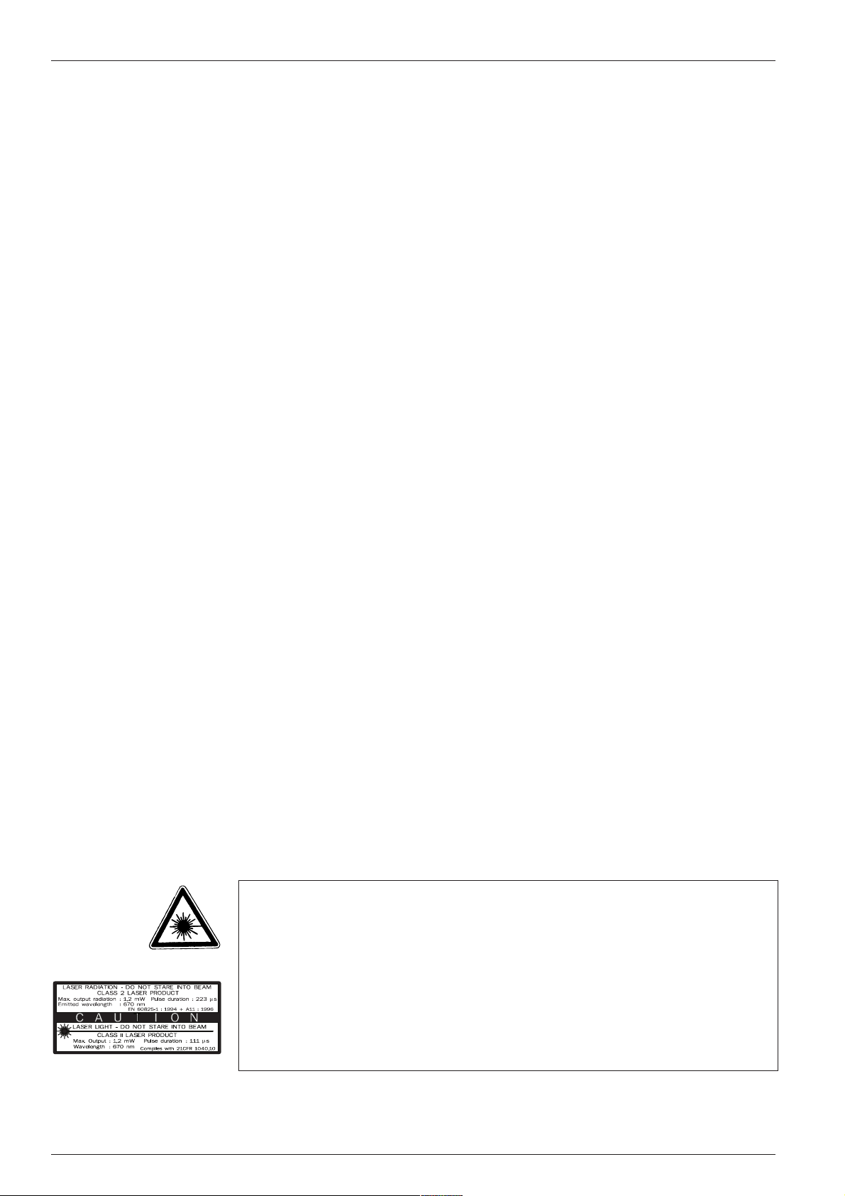
Laser radiation!
The radiation emitted by the laser diode (red or IR light) on the CLV 410 is harmful to
the human eye. For this reason, do not look directly into the laser beam.
WARNING!
Opening the housing while the device is in operation does not prevent the laser diode
from being activated by the reading pulse.
The maximum output power of the laser beam at the reading window is 1 . 2 mW.
The CLV, therefore, is assigned to protection class 2.
Laser radiation, do not stare into the beam, class 2 laser product.
Max. output radiation: 1 . 2 mW (223
µµ
µs), emitted wavelength: 670 nm
µµ
See Section 15 for further safety instructions!
4
© SICK AG • Auto Ident • Germany • All rights reserved
8 008 224/I982/08-00
Page 5
Operating Instructions
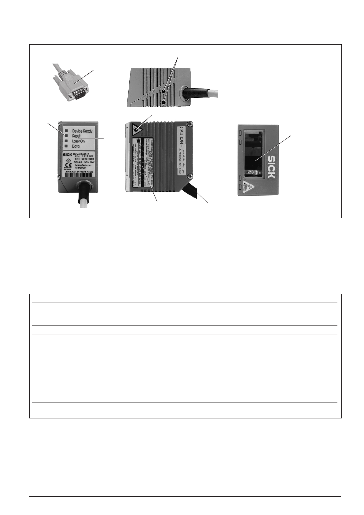
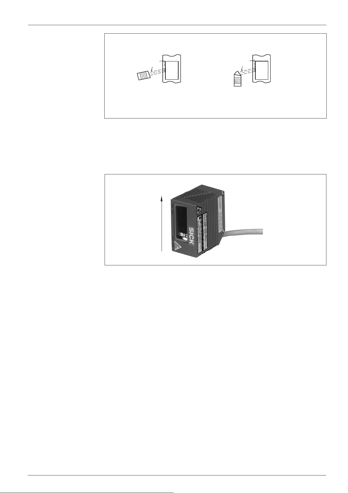
5. Design
CLV 41x Bar Code Scanner
/
Fig. 1. CLV 41x design
!
&
$
$
"
Key:
! D Sub HD connector, 15-pin
" Tapped blind hole M 4, depth: 6 mm
§ Reading window
$ Laser warning label
% Connection cable
& Sound opening of beeper (covered)
/ Function LEDs
§
%
6. Beeper function
The beeper
successfully or indicates a malfunction. The sound opening is located below the LED
label on the rear, narrow side of the device (Fig. 1).
Operating mode/function Beeper function Sequence
Reading mode
Percentage Evaluation The beeper confirms output of the reading result after every 100 reads 1. 1 tone
AutoSetup
Profile programming
Self-test The beeper signals successful completion of the self-test after power-up 1 . 1 tone
*)
After a laser timeout of 10 minutes (default), the beeper indicates with one long tone that the laser diode has been switched off
and that the reading pulse has been deactivated automatically.
Table 1
*)
*)
*)
1. The beeper confirms the start of reading mode when the device is switched on 1. 2 tones
after the wait time for teach-in mode has elapsed
2. The beeper confirms a good read (default setting) and output of the read result 2. 1 tone
1. The beeper confirms successful read of the presented profile bar code 1. 1 tone
for the start or end of AutoSetup
2. The beeper confirms successful read of the application-specific bar code 2. 1 tone
3. The beeper signals unsuccessful read of the application-specific bar code 3. 3 tones
after approx. 35 seconds
1. The beeper confirms successful read of the presented profile bar code 1. 1 tone
2. The beeper confirms the start of reading mode 10 s after the last profile 2. 2 tones
bar code has been read
6either provides an acoustic confirmation that a function was executed
8 008 224/I982/08-00
The beeper can be assigned a different result indicator function and the beeper
TIP:
volume changed (default: low) by means of the EDIT RESULT OUTPUTS field on the
D
EVICE CONFIGURATION card of the operating interface.
In these operating instructions, it is assumed that the beeper is operated
with the default settings.
© SICK AG • Auto Ident • Germany • All rights reserved
5
Page 6
CLV 41x Bar Code Scanner
Operating Instructions
7. Function of the LEDs
The LED function indicators 7 are located on the rear, narrow side of the device (Fig. 1).
LED Color Function
Device Ready green Indicates that the the CLV is ready (Reading mode). Lights up when the device is switched on, after
the self-test has been successfully completed and when the wait time for teach-in mode has expired.
The LED extinguishes when the device is switched to a different operating mode.
Result green Function depends on the operating mode of the scanner:
• In Reading Mode or Teach-in Mode, the LED indicates a successful read (good read).
If the match code comparison is activated, it lights up if the bar code read matches the specified
match code(s).
Device Ready
Result
Laser On
Data
Laser On green Lights up when the laser diode is activated for reading the bar code.
Data yellow Flickers when the CLV is transferring data to the host on the serial data interface
The LED lights up constantly until the start of the next reading pulse
• In Percentage Evaluation with 100 scans per reading interval, the LED indicates the trend in the
read quality as follows:
LED off good read rate < 30%
LED blinks (frequency 2 Hz) good read rate 30%...70%
LED blinks (frequency 5 Hz) good read rate 70% ... 90%
LED lights up constantly good read rate > 90%
• The LED lights up briefly when set to AutoSetup before it starts to scan the presented bar code
The laser diode is activated and deactivated by the reading pulse.
The laser diode is activated constantly in Percentage Evaluation and Free-running modes.
In Reflector Polling pulse mode, it is activated in accordance with the scanning frequency at every
20th scan (LED flickers).
The scan line(s) are dimmed (with red-light scanner only)
Table 2
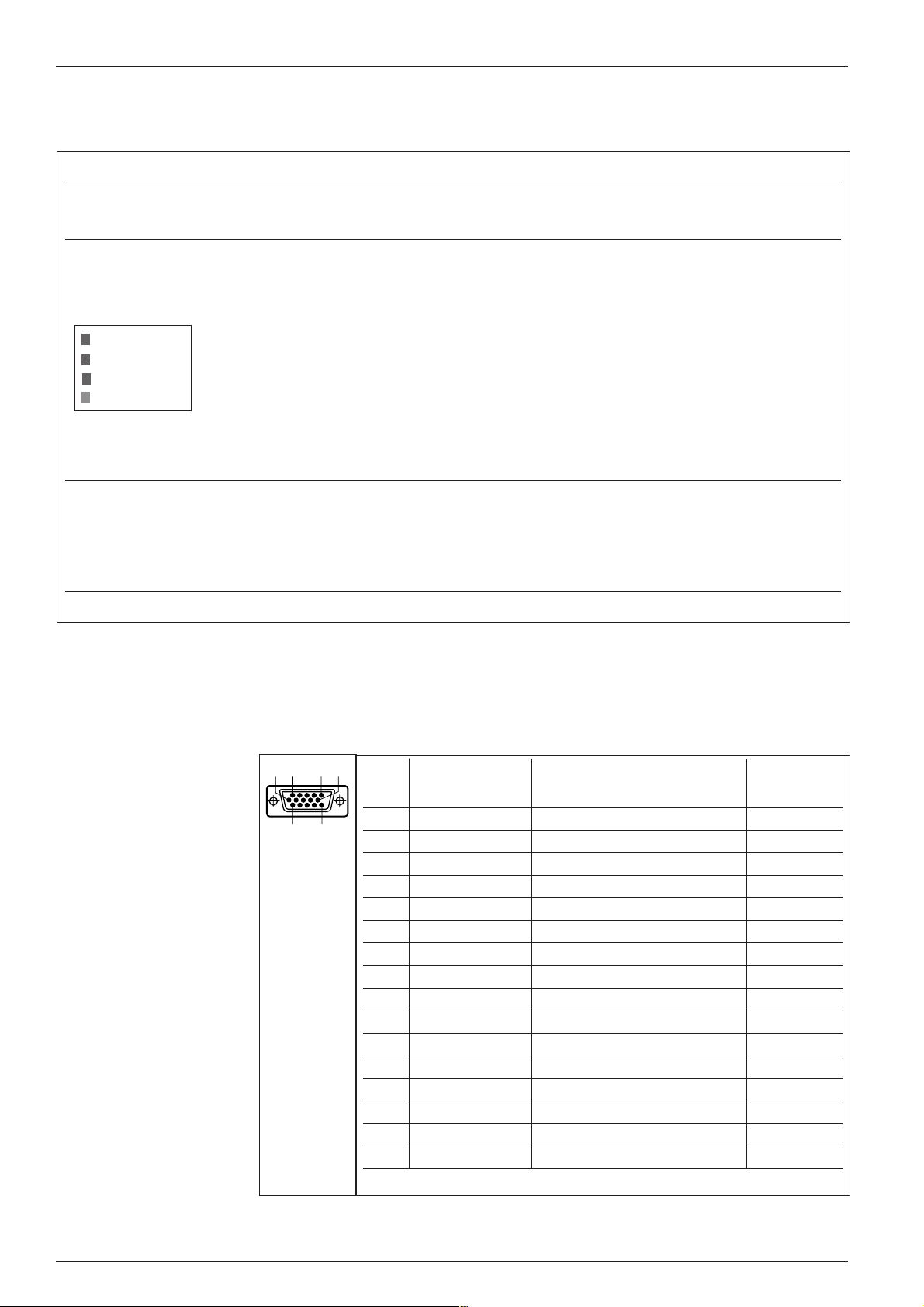
8. Electrical installation
8. 1 Pin assignment of connector
Pin Signal Function Wire colors
10
1 DC +4.5...+30 V Supply voltage red
2 Sensor 2 Switching input teach-in (match code 1) purple
3 Result 3 Switching output (to PLC) yellow
4 Term RS 422 Termination for data interface 1 red/black
5 GND Ground black
6 RD+ (RS 422/485) Data interface 1 (receiver) light blue
7 RD- (RS 422/485) Data interface 1 (receiver) blue
8 TD+ (RS 422/485) Data interface 1 (transmitter) gray/turquoise
9 TD- (RS 422/485) Data interface 1 (transmitter) green
10 RxD (RS 232) Data interface 2 (receiver) gray
11 TxD (RS 232) Data interface 2 (transmitter) pink
12 Result 1 Switching output (to PLC) brown
13 Result 2 Switching output (to PLC) orange
14 Sensor 1 Switching input for ext. reading pulse white
15 SensorGND Common ground (all inputs) black/white
– – Shield white/green
1) Cable with 15-pin D Sub HD socket and open cable end
11
5 6
1
15
of cable
no. 6 010 137
1)
Table 3
6
© SICK AG • Auto Ident • Germany • All rights reserved
8 008 224/I982/08-00
Page 7
Operating Instructions
CLV 41x Bar Code Scanner
8. 2 Supply voltage
The CLV 41x requires a supply voltage of 4.5 ... 30 V DC to IEC 742 (safety extra-low
voltage, listed class II power supply).
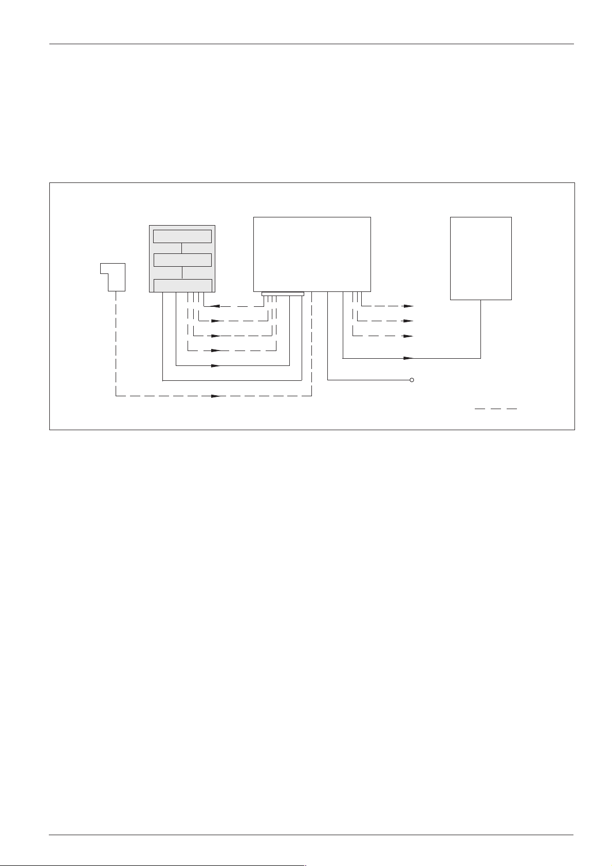
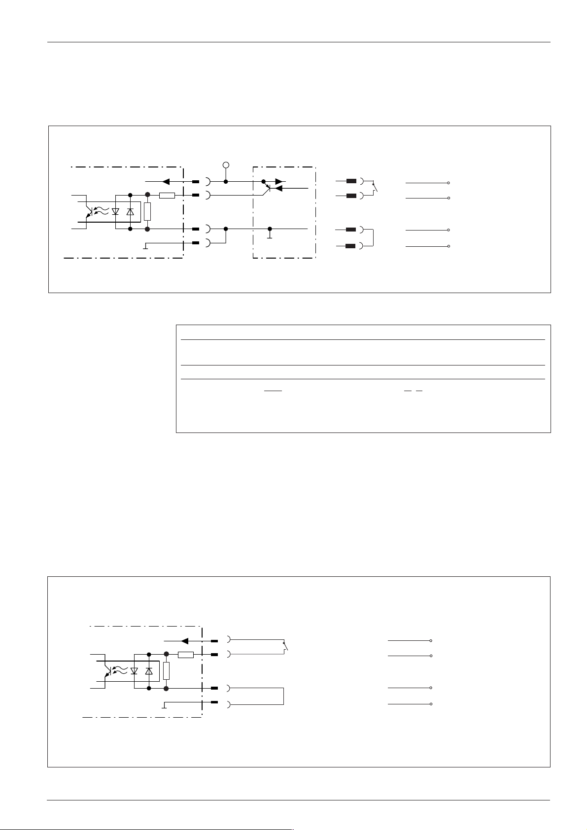
8. 3 Connecting the CLV to the AMV/AMS 40 (Connection Module)
Before it can be used in the reading station, the CLV must be connected to the
AMV/AMS 40 Connection Module and the host/PLC/sensor as shown in Fig. 2.
CLV 41x
Photoelectric
switch
Fig. 2. Block diagram: connecting the CLV in the reading station via the AMV/AMS 40 Connection Module
Scanner
Decoder
Interface
Sensor 1
Result 1
Result 2
Result 3
Data
DC 24 V
Sensor 1
TIP:
A description of the basic wiring and configuration of the Connection Module is
AMV/AMS 40
Connection
Module
Result 1
Result 2
Result 3
Data
PLC
24 V DC (AMV)
230 V AC (AMS)
provided in the AMV/AMS 40 Operating Instructions (no. 8 008 292) supplied with
the module.
Ø Mount the AMV/AMS 40 as close as possible to the CLV
HOST/PLC
Optional
cable
Ø Connect the CLV to the 15-pin D Sub HD socket of the AMV/AMS 40
The connection cable can be extended with extension cable no. 6 010 075 (2 m).
Ø Do not exceed the max. cable lengths (host interface) between the CLV and the
host/PLC (see 8.5.1 Connecting the host interface)
Ø Connect a suitable, external reading pulse sensor via the AMV/AMS 40 if reflector
polling (default setting) is not to be used for automatic reading pulse generation
Ø If an external power supply unit is used instead of the AMV/AMS 40, it must be
able to provide a continuous output of at least 3 W and must comply with IEC 742
(functional extra-low voltage). The core cross-section for the CLV power supply
2
(pins 1 and 5) must be at least 0.09 mm
.
Use cable no. 6 010 137 (open wire ends) to connect the CLV. See Table 3 for
wire color assignment
8 008 224/I982/08-00
© SICK AG • Auto Ident • Germany • All rights reserved
7
Page 8
CLV 41x Bar Code Scanner
5
1
9
6
Operating Instructions
8. 4 Connecting the PC to the CLV
A PC with Windows™ must be connected to the RS 232 port on the CLV to operate
and parametrize the device. There are two ways of connecting the PC:
1. Connect the PC COM x port to the internal terminals on the AMV/AMS 40
Ø Switch off the power supply to the Connection Module and the PC and connect
the PC and Connection Module as described in the AMV/AMS 40 Operating
Instructions
Ø Disconnect the CLV from the host if they are already connected (RS 232
interface)
Ø Switch on the PC and AMV/AMS
Ø Copy the operating and parametrization software CLV Setup and the online help
CLV Setup Help to the hard disk of the PC and install the software accordingly
Ø Set the communication parameters in CLV Setup for port COM x (S
ERIAL PORT
under OPTIONS) as shown in Table 4 (Default setting on CLV)
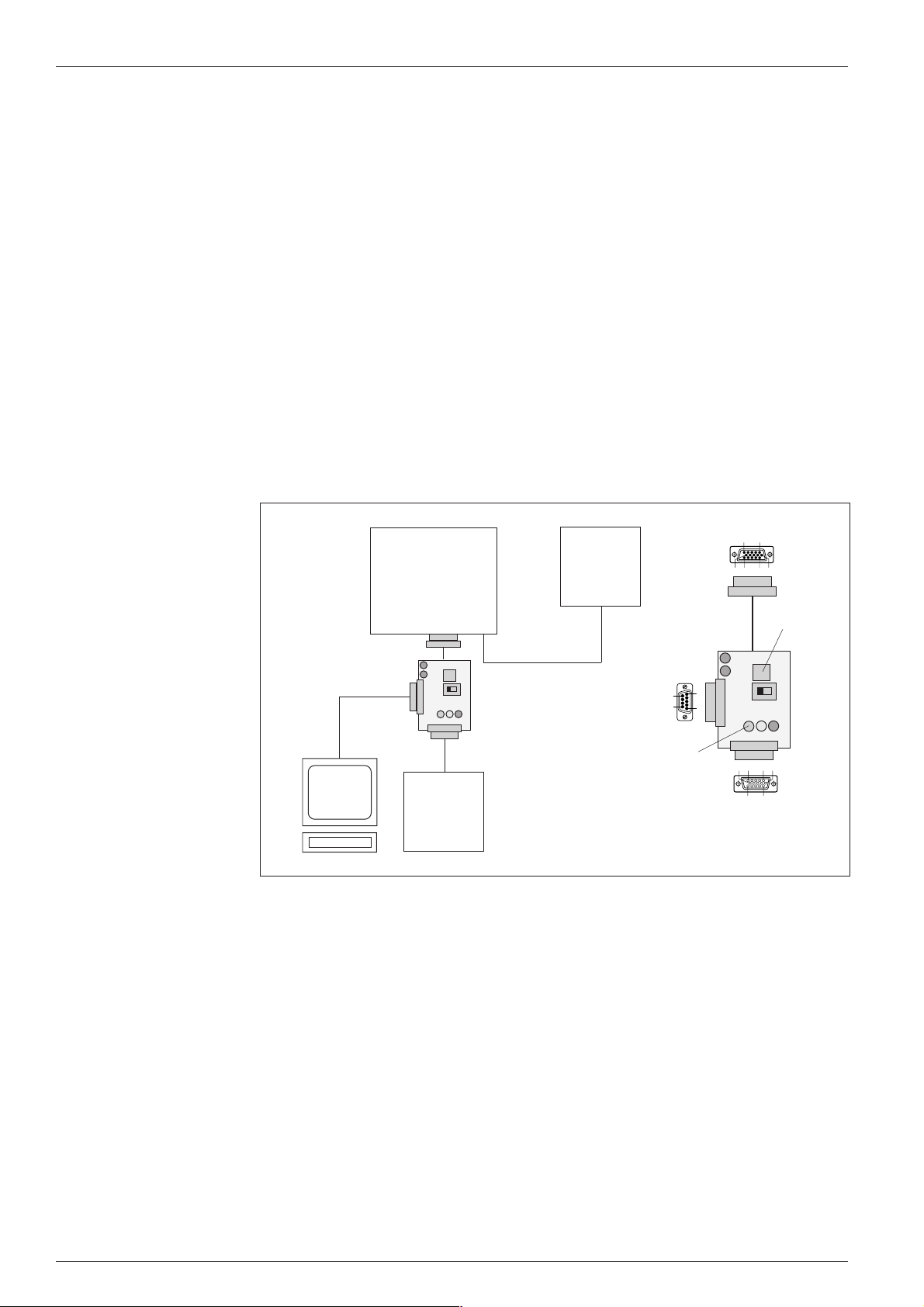
2. Connecting the PC port COM x via the optional programming adapter
e.g. cable
order no.
2 014 054
PC with
Windows
AMV/AMS 40
Connection
Module
CLV 41x
Programming
adapter
to AMV/AMS 40
Host/PLC
to PC
LED for
switching
outputs
Programming adapter
(order no. available on request)
11
15
11
15
5 6
10
1
510 61
Term
1 10
5
15 611
to CLV 41x
Clock
Host
123
Button
Fig. 3. Connecting the PC to the optional programming adapter
Ø Switch off the power supply to the Connection Module and PC
Ø Disconnect the CLV connector from the Connection Module (Fig. 3)
Ø Connect the 15-pin cable connector of the programming adapter to the socket on
the AMV/AMS 40. Connect the free 15-pin socket of the programming adapter to
the CLV connector. The adapter is supplied with power from the Connection
Module
Ø Connect the PC port COM x to the 9-pin connector of the programming adapter via
an RS 232 cable (e.g. no. 2 014 054)
Ø Set the slide switch on the programming adapter to TERM (the CLV is then
disconnected from host and communicates with the PC only). The PC is
disconnected from the CLV when the switch is set to HOST
Ø Switch on the PC and AMV/AMS
8
© SICK AG • Auto Ident • Germany • All rights reserved
8 008 224/I982/08-00
Page 9
Operating Instructions
CLV 41x Bar Code Scanner
Parameter Value
COM port freely selectable
Baud rate 9600 bit/s
Data bits 8
Parity none
Stop bit 1
Table 4
Ø Copy the operating and parametrization software CLV Setup and the online help
CLV Setup Help to the hard disk of the PC and install the software accordingly
TIP:
CAUTION
Ø Set the communication parameters in CLV Setup for port COM x (S
O
PTIONS) as shown in Table 4 (default setting of the CLV)
ERIAL PORT under
With the CLV pulse mode “Sensor Input“, the reading pulse can be triggered with the
Clock button on the programming adapter. For this purpose, choose the pulse mode
via the E
DIT READING PULSE field on the DEVICE CONFIGURATION card of the user interface
and download it to the CLV.
8. 5 Connecting the interfaces
All of the interfaces are routed via the 15-pin D Sub HD connector À (Table 3).
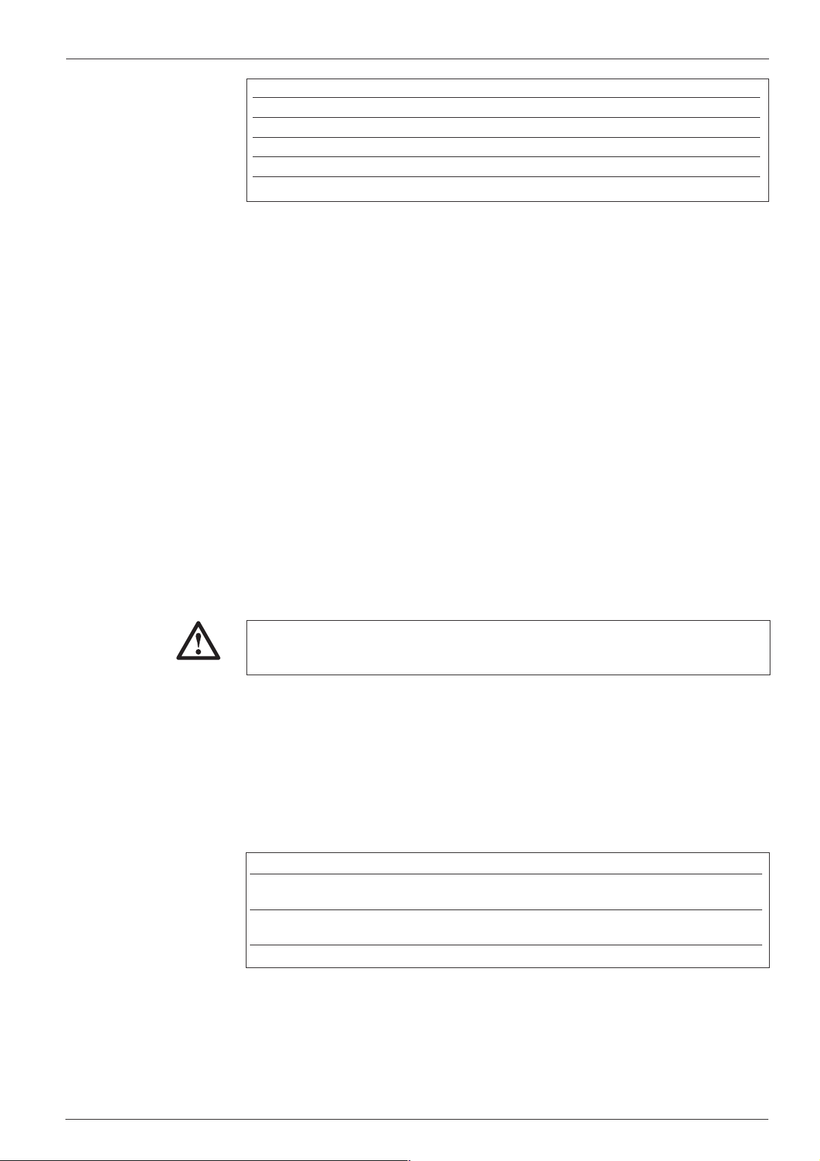
8. 5. 1 Connecting the host interface
The CLV is equipped with two host interfaces (RS 232 and RS 422/485). One of
these must be selected for data communication with the host/PC. If the RS 232
interface is not connected to the host, it can be used exclusively to monitor data
traffic on the parallel RS 422/482 interface.
The internal modules of the CLV may be damaged irreparably if the data interface
is connected incorreclty.
Ø Connect the host interface of the CLV to the host in accordance with the EMC
requirements using shielded cables(Fig. 4)
Ø To prevent interference, do not lay the data cables over a long distance parallel
to the power supply and motor cables, e.g. in cable ducts
Ø Apply the shield on one side (SICK recommendation)
Recommended max. cable lengths between the CLV and host:
Interface type Transmission rate Distance from host
RS 232 up to 19 200 bits/s max. 10 m
38 400 ... 57 600 bits/s max. 3 m
RS 422/485
1) with appropriate line termination
Table 5
1)
max. 38 400 bits/s max. 1 200 m
max. 57 600 bits/s max. 500 m
8 008 224/I982/08-00
© SICK AG • Auto Ident • Germany • All rights reserved
9
Page 10
CLV 41x Bar Code Scanner
Operating Instructions
RxD
RS 232
CLV 410
RS 422
CLV 410 Host
RS 485 (SICK Network): Connection diagram available on request
Fig. 4. Connecting the host interface
TxD
GND
RD+
RD–
TD+
TD–
GND
Term
10
11
5
6
7
8
9
5
4
TxD
RxD
GND
TD+
TD–
RD+
RD–
GND
Host
Terminal assignment
AMV 40-011/AMS 40-012, -013:
RxD
TxD
GND
R+
R-
T+
T-
GND
T. 10
T. 11
T. 5
T. 6
T. 7
T. 8
T. 9
T. 5
TIP:
IMPORTANT
The default communication parameters of the CLV host interface are as follows:
Parameter Value
Data transmission rate 9600 bit/s
Data bits 8
Parity none
Stop bit 1
Protocol Sick (start character: STX, stop character: ETX, no
repeat request: none, timeout: 50 ms)
Table 6
The parameters can be changed in the DATA FORMAT and INTERFACE PROTOCOL fields on
the H
OST INTERFACE card of the user interface.
By reading in profile bar code nos. 11 and 12 (Section 10.2 Default setting), you can
define the above default settings temporarily with a different parameter set to allow
the PC to communicate with the CLV.
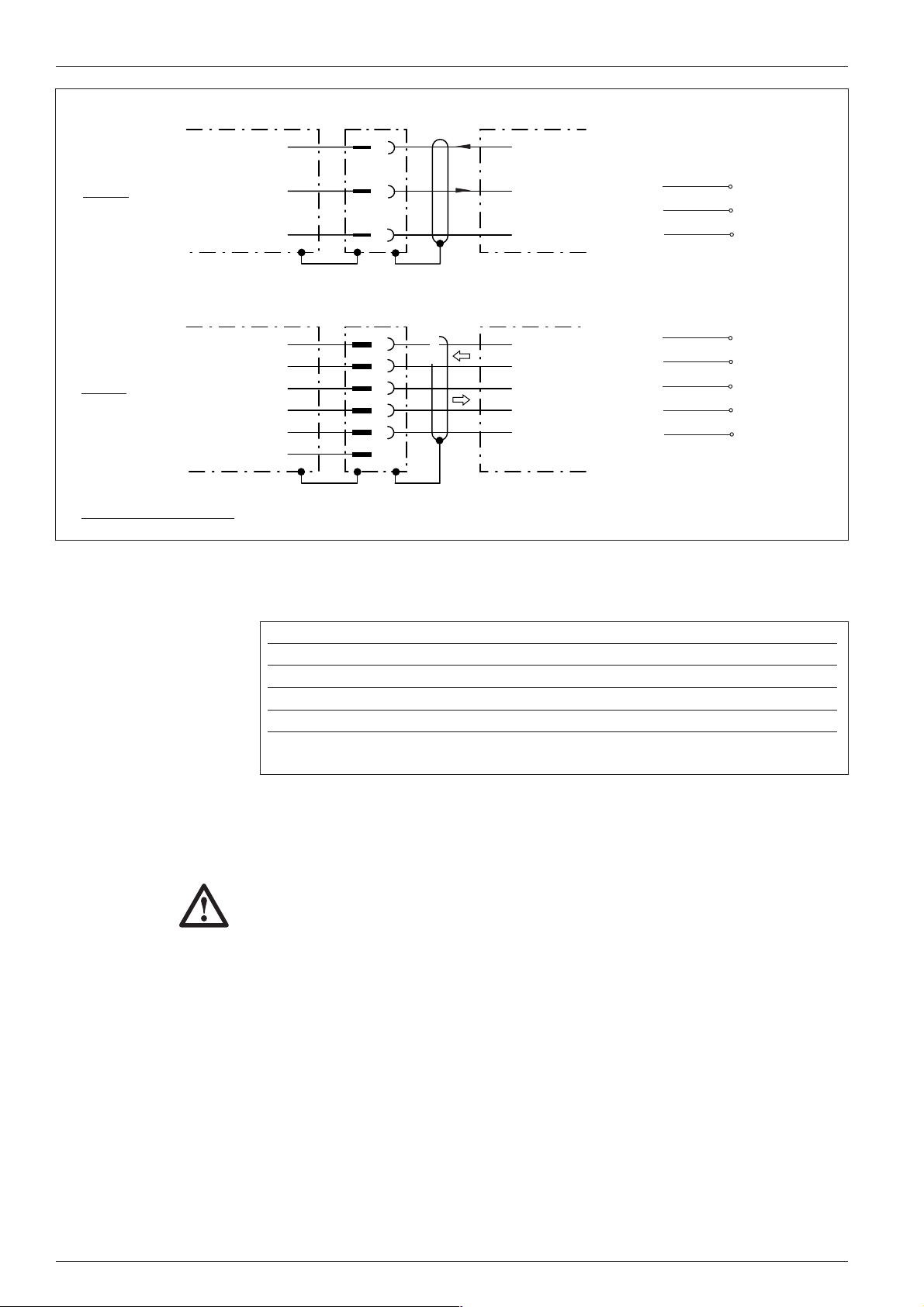
8. 5. 2 Connecting the functional interfaces
Sensor 1 switching input
In order to trigger a reading process, the CLV requires a suitable clock pulse in
Reading mode that signals the presence of a conveyor object in the reading field.
The clock pulse generates the reading interval (time window for evaluation) internally
in the CLV. In the default setting, the reading pulse is supplied by means of internal,
continuous reflector polling (see Section 9.2).
10
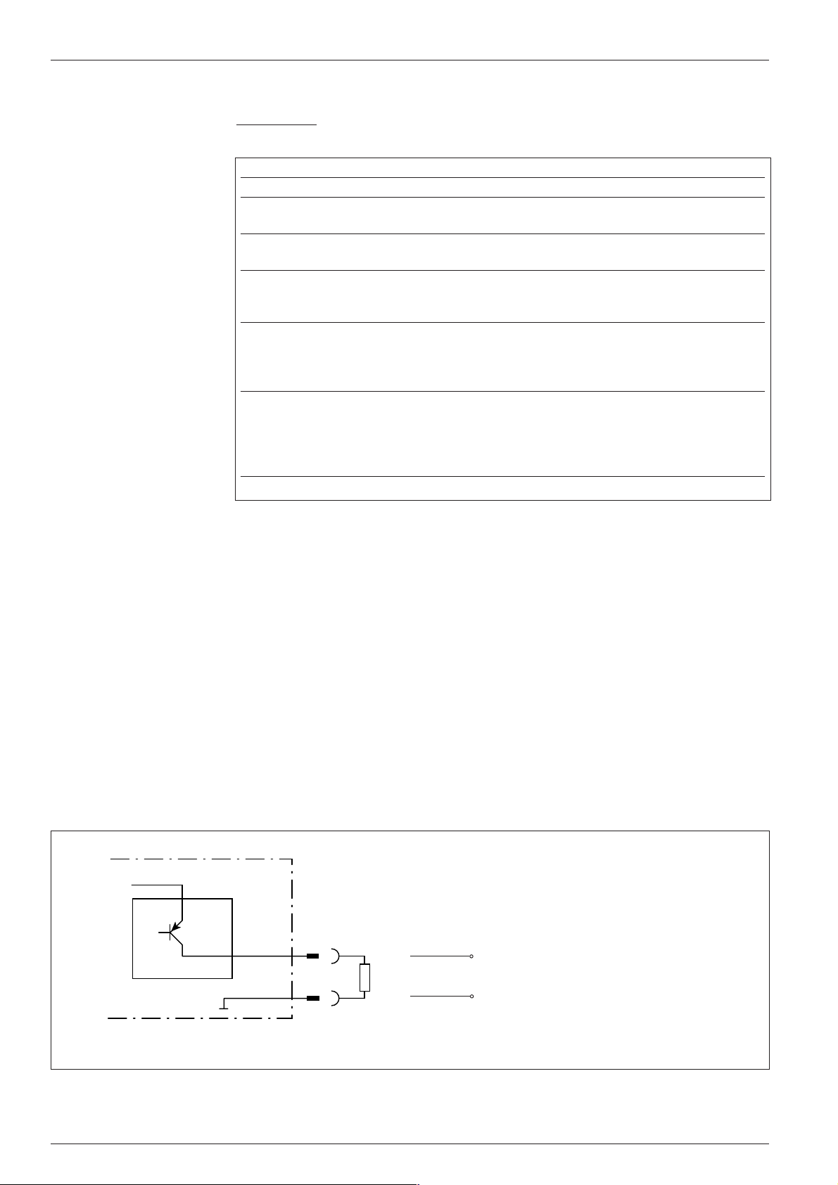
If an external sensor (e.g. photoelectric switch, switch) is to notify the CLV of the
presence of a conveyor object, the following steps must be performed:
Ø Connect the sensor to the CLV as shown in Fig. 5
© SICK AG • Auto Ident • Germany • All rights reserved
8 008 224/I982/08-00
Page 11
Operating Instructions
CLV 41x
CLV 41x Bar Code Scanner
Ø Set the trigger source to SENSOR INPUT via the EDIT READING PULSE field on the DEVICE
CONFIGURATION card of the user interface and download the parameter settings to
the CLV
An external clock pulse is not required for Percentage Evaluation operating mode.
Terminal assignment
V
S
DC 24V
PNP sensor
Switch
AMV 40-011/AMS 40-012 ,-013:
V
DC 24V
S
1K5
6K8
1K5
1
14
15
5
Sensor 1
Sensor
Sens GND
GND
DC 24V
V
S
GND
VS= +4.5...+30 V DC
Fig. 5. Connecting the Sensor 1 input to an external reading pulse sensor
Sensor 1 switching input
Switching Start internal reading interval when input
characteristics live (active high; default setting)
Properties opto-decoupled, non-interchangeable
Electrical values Low: -1V ≤ Vin ≤ +1 V High: -28 V ≤ Vin ≤ -3 V
-0.3 mA ≤ Iin ≤ +0.3 mA -18 mA ≤ Iin ≤ -1.4 mA
Table 7
1
14
15
5
V
S
SENS
SGND
GND
T. 18
T. 14
T. 15
T. 5
+3 V ≤ V
+1.4 mA ≤ Iin ≤ +18 mA
≤ +28 V
in
Sensor 2 switching input
This input is used exclusively to teach in match code 1. The teach-in procedure is
an alternative to entering the match code on the keyboard via the C
field on the DEVICE CONFIGURATION card of the user interface.
In order to teach in the match code, the input is connected briefly to the power
supply via a switch (Fig. 6). This can also take place in the Connection Module.
CLV 41x
V
DC 24V
S
1K5
6K8
1K5
Electrical values and properties:
as Sensor 1 (see Table 7)
VS= +4.5...+30 V DC
DC 24V
V
1
S
Sensor 2
2
14
Sensor
Sens GND
15
SensGND
5
GND
GND
DC 24V
Switch S
GND
ODE COMPARISON
Terminal assignment
AMV 40-011/AMS 40-012, -013:
V
S
Sensor 2
SGND
GND
T. 18
T. 2
T. 15
T. 5
Note:
Instead of the bridge the “GND-SGND“
Jumper can be set in the AMV/S 40.
Fig. 6. Connection of Sensor 2 input for teaching in match code 1
8 008 224/I982/08-00
© SICK AG • Auto Ident • Germany • All rights reserved
11
Page 12
CLV 41x Bar Code Scanner
Operating Instructions
Ø Procedure for teaching in match code 1
Prerequisite: CLV is in Reading mode and the current parameter set (if
application-specific) is stored permanently.
Step Action Response from CLV
1 Switch off CLV –
2 Close switch S and CLV switches to Reading mode and activates
switch on CLV again teach-in mode for the match code.
3 Open switch S CLV in teach-in mode and searches match
code.
4 Position match code at appropriate –
distance (see 16. Reading field
diagrams)
5 Trigger set reading pulse CLV reads the match code.
The Result LED lights up to confirm
successful read (good read; default setting).
Beeper emits a short acoustic signal.
6 Close switch S again CLV stores the match code and its code type
in the valid parameter set and permanently
in the EEPROM.
From this point on, it compares each match
code read with the match code taught in.
1) We recommend that you connect the PC with the CLV Setup interface to check the read result
Table 8
1)
Notes:
1. In order to replace the match code taught in in this way with a different match
code, you can repeat steps 3 to 6 without having to switch off the CLV.
2. If match code 1 is set using the teach-in method, it must not be modified with the
user interface (or command strings) until the CLV is switched off again. The
methods used to set the match code cannot be mixed. This does not affect
match code 2.
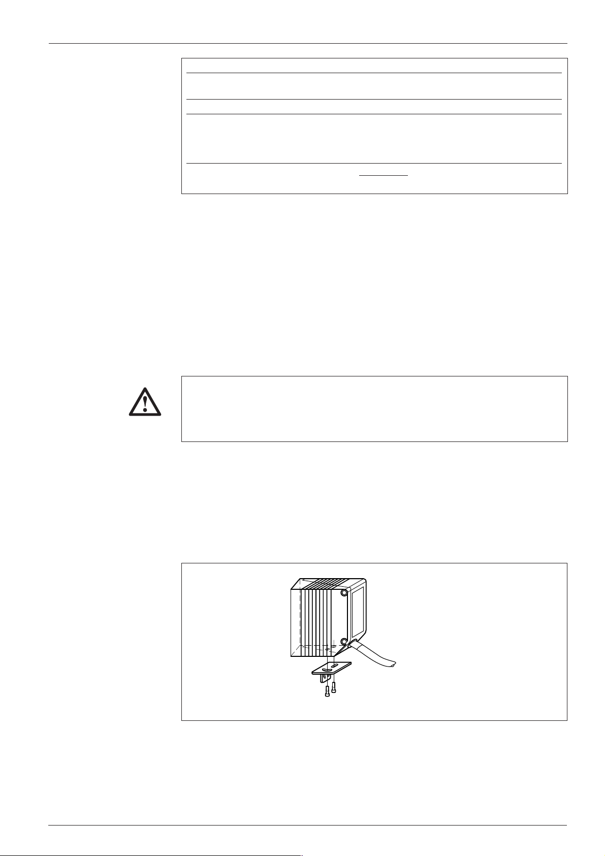
Result 1 to Result 3 switching outputs
The three outputs (Fig. 7) can each be assigned different result functions. When the
associated result occurs, the corresponding output becomes live for the selected
pulse duration at the end of the reading interval. The pulse duration can be set
separately for each output.
V
S
„Result 1“
12
5
CLV 41x
Configuration of Result 2 (pin 13/terminal 13) and Result 3 (pin 3/terminal 3): as Result 1 output
Fig. 7. Connection example: Result 1 output
Terminal assignment
AMV 40-011/AMS 40-012, -013:
Result 1
V
o
GND
T. 12
T. 5
VS= depending on
operating voltage applied
(+4.5...+30 V DC)
Pulse duration:
10 ms ... 9.9 s or static
(to end of next reading
pulse)
12
© SICK AG • Auto Ident • Germany • All rights reserved
8 008 224/I982/08-00
Page 13
Operating Instructions
9. Assembly
CLV 41x Bar Code Scanner
Result 1 to Result 3 switching outputs
Switching PNP-switching to supply voltage V
characteristics
Properties short-circuit + temperature-protected, not electrically isolated from V
Function assignment Result 1: Device Ready, polarity: not inverted
(default setting) Result 2: Good Read, polarity: not inverted
Result 3: No Read, polarity: not inverted
Pulse duration: 100 ms
Electrical values 0 V ≤ V
I
Out
Table 9
The function assignment, pulse duration and polarity of the signals can be modified
TIP:
via the E
DIT RESULT OUTPUTS field on the DEVICE CONFIGURATION card of the user interface.
≤ V
Out
≤ 600 mA
Guaranteed: V
S
S
≤ VS − 1.5 V at I
Out
The Result LED is not affected by this and lights up in Reading mode for a Good
Read until the end of the next reading pulse.
9. 1 Securing the CLV
≤ 600 mA
Out
S
CAUTION
The two fastening threads (2, Fig. 1) on the bottom, narrow side of the housing are
used to secure the CLV. The thread dimensions are shown in Section18. Dimensioned
diagrams.
Risk of damage to the housing
The max. depth of engagement of the two M 4 tapped blind holes is 6 mm from
the housing surface. Do not exceed this depth.
Mounting accessories
The CLV can be easily secured to the base to suit the relevant application using one
of the two optional mounting brackets (Fig. 8). This facilitates precise adjustment in
two planes. The dimensions of these brackets are shown in Section 18.
Dimensioned drawings. The elongated holes in the brackets allow the CLV to be
adjusted with a freedom of rotation of approx. ± 15°.
8 008 224/I982/08-00
Mounting bracket (small)
no. 2 020 077
Fig. 8. Mounting example: securing the CLV using the mounting bracket (accessory)
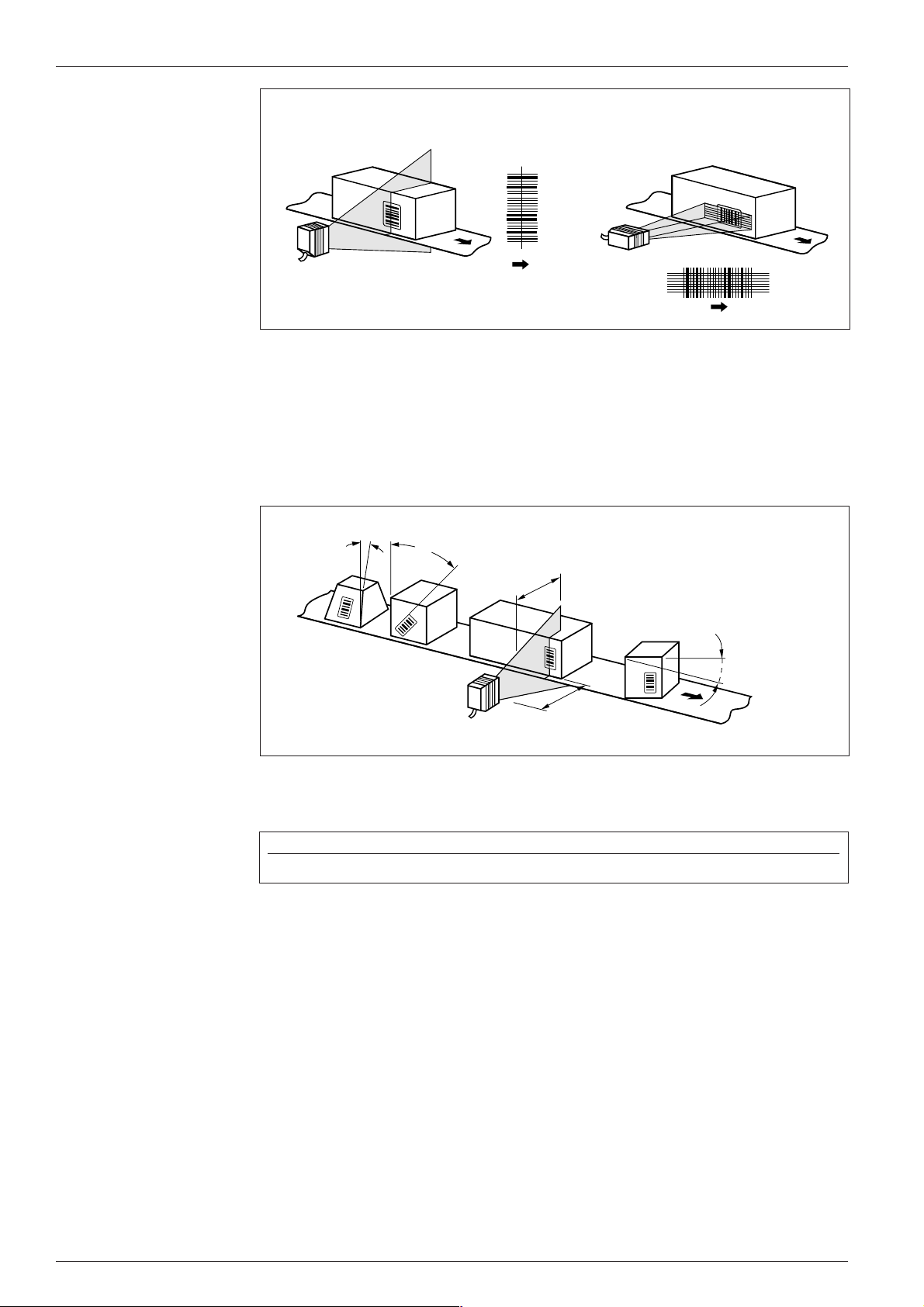
Aligning the CLV with the bar code
The alignment between the CLV and line or raster scanner depends on the
application. The basic alignment between the two scanning methods and the
conveyor object is shown in Fig. 9.
© SICK AG • Auto Ident • Germany • All rights reserved
13
Page 14
CLV 41x Bar Code Scanner
Operating Instructions
Line scanner Raster scanner
Fig. 9. Scanning method alignment relative to the bar code and conveyor direction
Reading angle and distance
When mounting the device, ensure that all of the possible reading angles at which the
bar code can be positioned relative to the scan line are taken into account. Fig. 10
shows this using a line scanner as an example. The reading window and code should
be almost parallel, whereby total surface reflection (see below) should be avoided.
β
α
Reading
range
α: Tilt
β: Pitch
γ: Skew
γ
Reading
distance
Fig. 10. Mounting example of CLV with line scanner: reading angles taken into account
The following angle limits should not be exceeded (CLV):
Angle Tilt α Pitch β Skew γ
Limit value 15° (depening on code print) 45° 45°
Table 10
When selecting the mounting location for the device, the limit values of the reading
range for the selected bar code resolution and the useful aperture angle (max. 60°
with front light emission) must be taken into account. See also Section 16. Reading
field diagrams.
14
Avoiding surface reflection
If the reading beam strikes the surface of the bar code vertically, reflection
interference may be caused when the returned light is received.
Ø Mount the CLV with front light emission (a) in such a way that the scan line(s) strike
the bar code at an angle less than approx. 15° from the vertical reference (Fig. 11).
Ø The CLV with lateral light emission (b) must be mounted flush so that the scan line
is emitted at an angle less than 105° relative to the housing.
© SICK AG • Auto Ident • Germany • All rights reserved
8 008 224/I982/08-00
Page 15
Operating Instructions
105°
CLV 41x Bar Code Scanner
Line scanner (Top view)
105°
a) CLV with front light emission b) CLV with lateral light emission
(flush mounting)
Fig. 11. Preventing surface reflection by rotating the CLV from the perpendicular
Count direction of code position CP
The CLV determines the position of the bar code within the scan line (CP value),
Fig. 12. This can be used to separate several identical bar codes (identical code
type, length and content) and output them accordingly.
100
CP
0
Fig. 12. CLV 41x: Count direction of the code position CP
9. 2 Mounting the polling reflector
In order to generate the reading pulse automatically using internal reflector polling
(default setting), one of the two polling reflectors supplied (special bar code) must
be mounted opposite the CLV behind the conveyor section.
Ø Note the maximum ranges of the two reflectors (Fig. 13)
Ø Mount the polling reflector (self-adhesive) opposite the CLV (in the alignment line)
in such a way that the CLV can view the reflector freely in the gaps between the
conveyor objects and can scan it reliably (center of scan line).
The scan line of the CLV should scan the code lines of the polling reflector
vertically.
8 008 224/I982/08-00
Ø Check the polling reflector installation for 100% read quality using the
Percentage Evaluation mode in the T
ERMINAL option of the user interface (see
Section 10.6). The CLV outputs the code content of the polling reflector and
signals REPO as the code type.
Function of reflector polling
In Reflector Polling pulse mode, the CLV activates the laser diode with every 20th
scan and checks whether it detects the reflector:
- if the reflector is still detected, the CLV repeates the procedure after the 20th
scan
© SICK AG • Auto Ident • Germany • All rights reserved
15
Page 16

CLV 41x Bar Code Scanner
Operating Instructions
blue
144
Distance:
500 ... 800 mm
50
144
• Reading distances (REPO)
Other distances must be respected
for CLV 412 and CLV 414. Only blue
REPO is allowed.
• Reading distances (REPO) CLV 412: 150 ... 350 mm
• Reading distances (REPO) CLV 414: 230 ... 650 mm
Fig. 13. Mounting the polling reflector (REPO)
white
50
Polling
reflector
Distance:
40 ... 500 mm
- the CLV starts the reading interval when the reflector is concealed by a conveyor
object in the reading field. The interval ends when the CLV detects the reflector
again. It then repeats the procedure above.
Notes:
This clock mode (max. delay approx. 100 ms at a scan rate of 200 Hz) is only
suitable for applications that are not critical with respect to time.
When the CLV is switched on, it must be able to detect the polling reflector. The first
reading interval can only start if this is the case.
In Reading mode, the CLV does not output the content of the polling reflector.
9. 3 Mounting the external reading pulse sensor (alternative)
If an external sensor (e.g. photoelectric switch) is used to generate the reading
pulse, it must be mounted on the CLV in a suitable manner. Ensure that objects of
different size carrying bar codes trigger the internal reading pulse in such a way that
sufficient time is provided to read the code. Examples of the CLV with line scanner
are provided in Fig. 14.
Bar code in the center or at the
end of the conveyor object
a
Bar code at the start of
the conveyor object
a
16
b
Fig. 14. Example of the position of the external reading pulse generator
b < a
b
b < a
Ø Choose the external sensor as the trigger source via the SENSOR INPUT field under
EDIT READING PULSE on the DEVICE CONFIGURATION card of the user interface and then
download the parameters to the CLV
© SICK AG • Auto Ident • Germany • All rights reserved
8 008 224/I982/08-00
Page 17

Operating Instructions
10. Power on and setup
CLV 41x Bar Code Scanner
Bar code sample
Code type: Code 39
Module width: 0.5 mm
UVWXYZ
10. 1 Step-by-step setup instructions
Quick start
Profile
programming
Ø Setup with the default settings
1. Connect the CLV to the 4.5...30 V DC power supply
(see also Section 8.1 Pin assignment of the connector)
2. Align the CLV with the white polling reflector supplied (special code),
distance approx. 300 mm
(see also Section 9.2 Mounting the polling reflector)
3. Present the bar code sample above at a distance of approx. 200 mm and
cover the polling reflector
(see also Section 10.6.1 Reading mode )
4. Uncover the polling reflector again
The CLV confirms that the read was successful with acoustic signal from the
beeper and the Result LED lights up
5. The CLV can now be operated with the default settings!
(see Section 10.2 Default settings of the CLV for the default settings)
Ø
Setup with profile bar codes (change parameter set)
1. Present the required printed profile bar code(s) on the card supplied
to the CLV
The CLV confirms every good read of the profile bar code with an acoustic signal
from the beeper. If a further bar code is not presented to the CLV within 10 s, the
CLV switches to Reading mode and outputs two consecutive acoustic signals
(see also Section 10.3 Profile programming)
Teaching in application-
specific bar codes
8 008 224/I982/08-00
2. The CLV can now be operated with the modified settings!
Ø
AutoSetup (modified code configuration)
1. Present bar code no. 10 to the CLV
The CLV confirms the start of AutoSetup by means of an acoustic signal from the
beeper and the Result LED lights up for an extended period of time.
(see also Section 10.4 AutoSetup)
2. Present the application-specific bar code to the CLV at the maximum
reading distance in the application
The CLV confirms the good read by means of an acoustic signal from the beeper
and the Result LED lights up. It then switches to Reading mode and outputs two
consecutive acoustic signals.
3. The CLV can now be operated with the modified code configuration!
The code type presented to the CLV is then evaluated
© SICK AG • Auto Ident • Germany • All rights reserved
17
Page 18

CLV 41x Bar Code Scanner
Operating Instructions
Alternative
procedure
Setup with CLV Setup software (change parameter set)
Ø
1. Connect the PC to the CLV
(see also Section 8.4 Connecting the PC to the CLV)
2. Start the CLV Setup program on the PC
(see also Section 10.5 Parametrization with the CLV Setup software)
3. Upload the configuration from the CLV
4. Change the configuration cards as required.
The parameters and their functions are explained in the online help.
5. Download the configuration to the CLV and store the values permanently
6. Save the modified parameter set on the PC as a configuration file!
Alternative:
5. Print out the profile bar codes and present them to the CLV in the specified
sequence
(see also Section 10.3 Profile programming)
Ø
Setup with command strings from the host
(not described here, further information is available on request)
10. 2 Default settings
A concise overview of the default CLV settings that are effective when the device is
switched on for the first time after delivery is shown in Table 11.
The tried-and-tested default parameters have been selected so that CLV can be
used directly in many applications without requiring modification.
Parameter Default setting (CLV 410)
Code types (active) Code 39, Code 128, Code 93, Codabar, EAN, EAN 128, UPC, 2/5
Interleaved
Code length Freely definable (all code types, except EAN and UPC, 2/5 Interleaved: 4...50
characters)
Multiple read 3 (all code types)
Min./max. no. of codes 1
Resolution 0.5 mm
Scanning frequency 500 Hz
Min. reading distance 50 mm
Reading pulse generation Start: polling reflector End: polling reflector
Beeper Result function: Good Read, volume: low
Switching outputs Result 1: Device Ready; Result 2: Good Read; Result 3: No Read
Protocol (Host) Start character: STX, stop character: ETX
Transmission rate (host) 9600 bits/s
Data format (host) 8 data bits, no parity, 1 stop bit
Output format (host) Header: blank, separator: blank, terminator: blank, error string: NOREAD+separator
Output sequence Code position
Output time Read result: end of pulse Separator: after code
Test string Inactive
18
Table 11
TIP:
You can call up the entire default settings from the CLV Setup program as follows:
Ø Choose F
ACTORY DEFAULTS in the FILE menu or
Ø Click the symbol.
© SICK AG • Auto Ident • Germany • All rights reserved
8 008 224/I982/08-00
Page 19

Operating Instructions
CLV 41x Bar Code Scanner
Printing out the
default settings
IMPORTANT
The CLV must not be connected with the PC (offline mode). The default setting
values are stored permanently in the user interface and on the CLV. The parameter
values are displayed in the menu options of the individual configuration cards. You
can print out the entire default settings by clicking the icon.
Note:
When you make changes to the default settings, we recommend that you save them
as a different configuration file (*.scl) on the PC using the S
AVE AS option in the
program.
Temporary host interface defaults
In order to allow you to access the CLV with the PC at any time, you can set the
host interface temporarily to the default setting (9600 bits/s, 8 data bits/1 stop
bit, no parity) using the profile bar codes:
Ø Present profile bar code no. 11 to the CLV in Reading mode and supply
an appropriate clock pulse to the device.
The CLV resets the host interface to the default values and confirms this with
an acoustic signal from the beeper. It then resumes Reading mode
immediately
Ø To restore the previous host interface configuration on the CLV, present
profile bar code no. 12 to the CLV.
The CLV confirms that the values have been reset with an acoustic signal and
resumes Reading mode immediately.
Parametrization
without a PC
IMPORTANT
Alternative:
Ø Switch the CLV off and on again to return to the original configuration
10. 3 Profile programming
Profile programming uses special bar codes to change the CLV parameters directly
without having to connect the PC with user interface. The profile bar codes are
simply presented to the CLV. The device then transfers the coded parameter values
to the current parameter set and stores them permanently. The changes remain valid
after the programming procedure has been completed and affect the further reading
procedure. The CLV waits 10 s after each profile bar code. If no more profile bar
codes are presented, it resumes standard Reading mode and confirms with two
consecutive acoustic signals.
Since the CLV overwrites important parameter values (e.g. those generated with
AutoSetup) without requiring confirmation, we recommend that you upload the valid
parameter set to the PC and store it as a configuration file (*.scl) with the S
option in the user menu before you change the parameter settings.
You can program the CLV at any time in Reading mode. Alternatively, you can present
one or more profile bar codes to the CLV for reading within 5 seconds after the
device has been switched on and the self-test has been completed (free-running).
The CLV does not output any reading results during profile programming and does
not respond to an external reading pulse.
AVE AS
8 008 224/I982/08-00
© SICK AG • Auto Ident • Germany • All rights reserved
19
Page 20

CLV 41x Bar Code Scanner
IMPORTANT
Operating Instructions
Printed profile bar codes
A total of 12 selected profile bar codes are provided on the „Configuration Profiles
for CLV 41x Bar Code Scanner“ card to make important changes (from the default
settings or the application-specific parameter set respectively). By folding the
individual segments of the card, you can ensure that the CLV only reads the
required profile bar code. The function of the profile bar codes is explained in
Table 12.
If you cannot access the host interface of the CLV from the “CLV Setup” user
interface (e.g. baud rate or data format not in line with default settings), the profile
bar code no. 11 can be used temporarily to set the CLV to the default settings
(host interface). To reset the system, use profile bar code no. 12 or switch off CLV.
Barcode Function
Profile 1 Default settings for all parameter values on the CLV
(Code configuration: all code types are enabled for evaluation).
Overwrites the code configuration generated by AutoSetup!
Profile 2 Changes the configuration on the host interface only:
- Data transmission rate: 38400 Bits/s
- Data format: 8 data bits, no parity, 1 stop bit
- Repeat request: none
Profile 3 Changes the configuration on the host interface only:
- Activates RS 422/485 interface
- SICK network protocol (standard)
- Data transmission rate: 38400 Bits/s
- Data format: 7 data bits, odd parity, 1 stop bit
- Device number: 99
Profile 4 Changes the configuration on the host interface only:
Outputs the read result immediately after the evaluation criteria have been fulfilled
Profile 5 Changes the configuration on the host interface only:
- Outputs the error status ST in the separator
- CLV outputs: CR LF in terminator (at the start of the line after every code)
Profile 6 Parameterizes the CLV as Master in master/slave configuration
- No. of slaves: 1
- Timeout: automatic
Profile 7 As profile 6, but no. of slaves: 2
Profile 8 Parameterizes the CLV as Slave in master/slave configuration
Profile 9 Parameterizes the CLV for pass-through mode:
Outputs “ / “ and the device number in the header
Profile 10 Starts or ends AutoSetup
Profile 11 Resets the host interface parameters to the defaults temporarily
Profile 12 Returns the host interface parameters to the original values
20
Table 12
The function of the individual parameters is explained in the online CLV Setup Help.TIP:
© SICK AG • Auto Ident • Germany • All rights reserved
8 008 224/I982/08-00
Page 21

Operating Instructions
CLV 41x Bar Code Scanner
Ø Profile programming procedure
Prerequisite: Valid parameter set (default settings or application specific)
stored permanently in CLV (EEprom).
Step Action Response from CLV
1 Present the required, printed profile CLV confirms a good read with an acoustic
bar code or the profile bar code signal and transfers the new values to the
generated with the software valid parameter set. This does not have any
(in the order in which it was effect yet
printed) to the CLV at a distance of CLV sets the timer and waits 10 s for the
approx. 200 mm. next profile bar code (the reading interval
Trigger reading pulse! remains active).
2 If the CLV is switched off, switch CLV switches to teach-in mode for 5
on the device and continue as seconds after the acoustic signal
described in step 1, reading (free-running mode).
pulse is generated automatically
3 Present the next profile bar code As described in step 1.
within 10 s
4 Complete the procedure by waiting CLV now stores the new values permanently
10 s after the last profile bar code in the EEPROM and switches to Reading
has been presented mode (two consecutive acoustic signals
from the beepers). The new parameters
take effect immediately.
1) in the case of profile nos. 11 and 12, the host interface parameters are affected immediately
1)
.
Printing out
profile bar codes
Table 13
Note:
When changing the reading pulse type, we recommend that you present the
corresponding profile bar code (3 LT...) last so that reading of further profile bar
codes in free-running mode is not interrupted.
Printing out profile bar codes via the user interface
You can print out the profile bar codes offline (CLV not connected to PC), for
example, using the modified values in the configuration cards. One or more profile
bar codes are printed out on a page, depending on the number of changes made to
the default settings. You can set the size, position and number of codes printed out
on the page as required. Longer profile bar codes must be printed out in landscape
format (using the printer configuration window).
Ø Procedure for printing out profile bar codes
Step Action
1 Start the CLV Setup program on the PC
2 Open the stored configuraiton file (*.scl) for the CLV
3 Change the relevant parameters in the configuration cards
4 Define the print conditions using the C
in the PROFILES menu or accept the defaults
5 Print out the profiles using the PRINT PROFILES menu option in the
PROFILES menu
6 Save the modified parameter set to a new configuration file (*new.scl)
ONFIGURE PRINTING menu option
8 008 224/I982/08-00
Table 14
© SICK AG • Auto Ident • Germany • All rights reserved
21
Page 22

CLV 41x Bar Code Scanner
Operating Instructions
10. 4 AutoSetup (code configuration)
Teaching in application-
specific bar codes
IMPORTANT
The AutoSetup function allows you to set the application-specific parameters
automatically to read
• a bar code (from a code type with a fixed code length)
• at a fixed reading distance.
For this purpose, the PC with the user interface must not be connected .
During AutoSetup, the CLV automatically determines the code type, code length and
the optimum scanning rate in free-running mode for the bar code presented at the
maximum reading distance. All other code types are disabled for further
evaluation. The CLV writes the parameter values to the parameter set directly and
stores it permanently (EEPROM).
Since the CLV overwrites important code configuration parameters without requiring
confirmation from the user, we recommend that you upload the valid CLV parameter
set to the PC and store it as a configuration file (*.scl) using the S
AVE AS menu option
in the user interface before you change the CLV parameters.
AutoSetup can be started at any time in Reading mode by presenting profile bar
code no. 12 and triggering the corresponding reading pulse. Alternatively, the CLV
can read profile bar code no. 12 in free-running mode directly after the device has
been switched and within the wait time of 5 seconds after the self-test has been
completed.
The CLV does not output any reading results during teach-in mode and does not
respond to an external reading pulse.
Note:
The CLV does not enter any real values for the Minimum Distance and Minimum Bar
Width parameters, since it cannot determine absolute dimensions. When you upload
the parameter set from the CLV to the PC, therefore, the values in the R
CONFIGURATION card do not correspond to the actual values.
AutoSetup can also be called under the T
TIP:
choosing the corresponding entry in the V
ERMINAL menu of the user interface by
IEW menu. The CLV, however, does not
output any reading results here. By connecting the PC, you can also subsequently
check the read quality of the bar code that was read in by switching to P
EVALUATION mode.
Ø AutoSetup procedure with profile barcodes
Prerequisite: Valid parameter set (defaults or application-specific)
stored permanently in the CLV (EEPROM).
Step Action Response from CLV
1 Present profile bar code no. 10 CLV confirms the good read with an acoustic
printed on the card at a distance signal and the Result LED lights up for an
of approx. 200 mm. extended period of time.
Trigger reading pulse! AutoSetup is started, the CLV is in
free-running mode.
2 If the CLV is switched off, CLV switches to teach-in mode for 5
switch on the device, seconds after the first acoustic signal
then proceed as described in step 1, (free-running mode).
reading pulse is triggered automatically
EADING
ERCENTAGE
22
Table 15
© SICK AG • Auto Ident • Germany • All rights reserved
8 008 224/I982/08-00
Page 23

Operating Instructions
CLV 41x Bar Code Scanner
Step Action Response from CLV
3 Present the application-specific a) CLV confirms the good read with an
bar code at the maximum acoustic signal and permanently
reading distance in the application overwrites the corresponding parameters
for up to 10 seconds (see also in the code configuration.
16. Reading field diagrams) It then outputs two consective
acoustic signals and switches to Reading
mode. The Device Ready LED lights up.
b) If the CLV does not detect a bar code
within approx. 35 s (e.g. incorrect reading
distance, poor print quality), three
acoustic signals are output. AutoSetup
is then restarted automatically.
4 After the three acoustic signals, adjust a) As 1 a
the reading distance or skew (scan b) The CLV cancels AutoSetup automatically
line angle relative to bar code) after three unsuccessful attempts
5 Cancel AutoSetup prematurely: CLV cancels Autosetup automatically and
present profile bar code no. 10 switches to Reading mode (two consecutive
again acoustic signals). The current parameter
set is not modified.
Table 15 (contd)
Ø Test read of the bar code taught in with AutoSetup
Prerequisite: AutoSetup successfully completed
Step Action Response from CLV
1 Call PERCENTAGE E VALUATION mode CLV displays the evaluation results for
from the TERMINAL menu 100 scans.
of the user interface
(see also Section 10.6 Operating
modes/functions)
2 Present the application-specific CLV displays the reading quality obtained
bar code again. at the corresponding distance.
Table 16
10. 5 Parametrization with the CLV Setup software
10. 5. 1 Installing the user and parametrization software
In order to switch between operating modes and set the parameters manually, you
need the Windows-based CLV Setup software supplied with the device. The program runs on Windows 3.11™, Windows 95™ and Windows NT™. The user interface
can also be used when it is not connected to the CLV to configure applicationspecific parameter sets (offline mode). The CLV must be connected to the PC,
however, to transfer modified parameter values (download) directly (online mode).
8 008 224/I982/08-00
Ø Copy the CLV Setup and CLV Setup Help software to the hard disk of your PC and
install the programs.
The user interface (Fig. 16) is largely self-explanatory. The introduction and online
CLV Setup Help function demonstrate how easy it is to use.
The data displayed on the configuration cards is first stored temporarily to the main
memory of the PC. You can save this data permanently to a configuration file (*.scl)
on the PC using the S
© SICK AG • Auto Ident • Germany • All rights reserved
AVE AS command in the FILE menu.
23
Page 24

CLV 41x Bar Code Scanner
Operating Instructions
From this point onwards, it is assumed that the user has started the program
and that the CLV is connected to the PC. Any existing data connections to the
host must be disconnected.
IMPORTANT
Fig. 15. Windows-based CLV Setup program
Initial steps after the user interface has been started
Displaying the default settings in the configuration cards
The program then loads the internal description of the CLV as well as the default
parameter values and displays them on the tabs. Finally, CLV Setup uploads the
current parameter set from the RAM of the CLV and displays the values on the tabs
instead of the default values.
You can edit the current parameter set on the tabs. The default values are displayed when
the device is used for the first time.
Troubleshooting
If the CLV-setup screen shows “no connection” in the lower right menu bar, the
program couldn’t connect to the CLV. There may be two reasons, either the CLV is
not connected or the communication parameters of CLV and PC do not match. The
CLV setup program stores the type of CLV which was successfully contacted before
in the list field “appliance” of the symbol bar. When calling the CLV setup program
for the first time the CLV type is by default “CLV 41x”. For this CLV type, the
program loads the internal appliance description and the default parameters from its
data base and displays the values in the corresponding tabs.
24
Displaying the active CLV parameter set
To view the active CLV parameter set and change it via the configuration cards, you
must first either
Ø transfer (upload) it from the CLV to the PC or
Ø open the active configuration file (*.scl) on the PC.
© SICK AG • Auto Ident • Germany • All rights reserved
8 008 224/I982/08-00
Page 25

Operating Instructions
CLV 41x Bar Code Scanner
Temporary default host interface settings
If you cannot access the CLV via the host interface after you start the device (red
indicator at the bottom right displays N
O CONNECT!)
IMPORTANT
IMPORTANT
IMPORTANT
Ø upload the parameter set from the CLV or
Ø present profile bar code no. 11 after you switch on the CLV (see also Section
10.3 Profile parametrization)
10. 5. 2 Setting the parameters via the configuration cards
After the start of the CLV setup program, the cards display the parameter values of the
current CLV.
Upload
The ”CLV Setup” loads the current parameter settings of the CLV to the database
and displays the values of the configuration cards. During the data transfer, the
„Device Ready“ LED is off.
If the ”CLV Setup” software is unable to read the loaded parameters during the
upload, a warning is issued. Unknown parameters can be edited in the “EXTRAS”
tab, following the general rules for command strings. When saving the parameter
set, these parameters are taken into account.
Download
The changes made to the configuration cards do not take effect until they have
been transfered to the CLV. When you download the file, the CLV asks you whether
you want to store the new parameter set temporarily or permanently.
TIP:
Quick help
TIP:
If the current parameter set has been changed and transferred to the CLV
permanently, we recommend that you back up this parameter set by saving it as a
configuration file (*new.scl) on the PC using the S
AVE AS command.
Online Help function
The parametrization procedure is supported by the online CLV Setup Help function.
The online help runs on an HTML browser (e.g. Netscape™ or Internet Explorer™).
The PC searches for this browser and opens it automatically. If it cannot be found, a
window is displayed asking you to specify the directory in which the browser is
stored on the hard disk.
You can call context-sensitive help on the parameter you are currently processing by
pressing F1. You can choose the configuration card on which you want help in the
top, horizontal frame. The associated parameters are then displayed in the left-hand
frame. When you click one of these parameters, a detailed description is displayed
in the right-hand frame. To display the help overview, choose the C
ONTENTS command
in the HELP menu.
To prevent several browser windows from being opened, we recommend that you
use the ALT + TAB keys in Windows to switch quickly between the CLV Setup and
CLV Setup Help applications.
8 008 224/I982/08-00
© SICK AG • Auto Ident • Germany • All rights reserved
25
Page 26

CLV 41x Bar Code Scanner
Operating Instructions
Note:
Printing out parameter sets
TIP:
You can print out and archive new parameter sets by clicking the
icon.
The manual entitled Menu-Driven Parametrization of the CLV Bar Code Scanner
explains the parameters and their functions and can be used as a reference for
more complex applications.
Ø Procedure for setting parameters via the configuration cards
Step Action
1 Connect the CLV to the PC
2 Start the CLV Setup program on the PC
2 Open the configuration file (*.scl) for the relevant CLV or click the
(upload) icon (CLV transfers the active parameter set to the PC)
3 Modify the required parameters in the configuration cards
4 Click the (download) icon (CLV receives the modified parameter set)
5 Choose the storage option*) for the CLV in the dialog window
6 Save the modified parameter set as a new configuration file (*new.scl) on the PC
*) permanently?:
The CLV saves the modified parameter set in the main memory (RAM) to the EEprom.
These values remain stored when you switch off the device. The next time you switch on the CLV, these
values are loaded to the main memory of the CLV and are used as the active parameter set.
temporary?:
The CLV only transfers the modified parameter set to the main memory (RAM). These values are lost
when you switch off the device. The parameter set last stored in the EEprom is loaded to the main
memory and used as the active parameter set the next time you switch on the CLV.
Table 17
Function of the configuration cards
Reading Configuration
This card is used to change the scanning frequency, reading distance, resolution,
start/stop ratio and the evaluation range of the scan line.
Device Configuration
This card is used to change the device number, reading pulse, output time of the
reading result and the separator in the data output string as well as the functional
assignment of the three switching outputs Result 1...3 and the beeper.
Code Configuration
This card is used to activate/deactivate the individual code types that are to be
evaluated and to change the number of identical reads as well as the minimum and
maximum number of bar codes to be read/output.
We recommend that you only activate those codes that are actually relevant in order
to enhance the reading reliability with fast applications.
26
© SICK AG • Auto Ident • Germany • All rights reserved
8 008 224/I982/08-00
Page 27

Operating Instructions
CLV 41x Bar Code Scanner
Host Interface
This card is used to change the protocol, start and stop characters, data format and
the transmission rate.
Data Strings
This card is used to change the data output format of the host interface. ASCII
characters and reading diagnosis data can be transferred to the host in the header,
separator and terminator (default setting: no characters). The output format for no
reads and the content of the error string can be modified. The test string function
can also be activated here. If more than one bar code is to be read during each
reading pulse, you can specify the output sequence and sort criteria.
Extras
If required, these tabs are used to treat parameters, which are unknown to the CLV
setup program after an upload from the CLV.
Note:
The program “CLV-Setup Help” describes the functionality and the allowed values of
the parameters. Call “CLV-Setup Help” by pressing “F1”.
8 008 224/I982/08-00
© SICK AG • Auto Ident • Germany • All rights reserved
27
Page 28

CLV 41x Bar Code Scanner
Operating Instructions
10. 6 Operating modes/functions
The CLV features the following operating modes/functions:
• Reading mode
• Percentage evaluation
• Profile programming
• AutoSetup
• Parametrization
• Operating data
10. 6. 1 Reading mode
Standard mode
Read quality
evaluation
The CLV switches to this mode automatically when it is switched on and after the
self-test has been successfully completed. In the default setting, the CLV generates
the reading pulse by means of reflector polling. The reading result is output at the
end of the reading pulse.
You can use the software to display the reading result from the CLV directly:
Ø Choose the T
window is then displayed in R
ERMINAL command in the FILE menu or click the icon. The terminal
EADING MODE
Ø Present the polling reflector to the CLV (start of reading interval), and then the bar
code to be read followed by the polling reflector again (end of reading interval)
10. 6. 2 Percentage evaluation
This temporary operating mode is only accessible via the user interface and is used
to assess the quality of the reading function. In this case, the CLV evaluates 100
scans statistically (independent of the set pulse type) in free-running mode. It
outputs the reading result continuously. You can view the results with the user
interface.
Ø Choose the T
Ø Click the terminal mode P
ERMINAL command as described above
ERCENT EVA L on the right of the screen (Fig. 17)
28
Fig. 16. Percentage Evaluation in the TERMINAL option of the user interface
© SICK AG • Auto Ident • Germany • All rights reserved
8 008 224/I982/08-00
Page 29

Operating Instructions
Good Read:
CLV 41x Bar Code Scanner
Ø Present the bar code shown in Fig. 18, for example, to the CLV at a reading
distance of approx. 200 mm (see Section 14. Sample bar codes for further
patterns). The CLV reads the bar code and displays the result on the screen. An
acoustic signal is output at the same time to confirm the read. The Result LED
lights up or blinks, depending on the read quality (see also Section 7. Function of
the LEDs).
T T= _ _210 ms MG=_46 % n=_1
C39 100% ST=0 CP=_50 CL=_6 CA=100 CS=100 CK=100
UVWXYZ
where:
*)
= Duration of reading interval
T T
MG*)= Time average of identification quality
*)
= Number of codes detected
n
C39*)= ID, code type Code 39
100%*)= Identification quality
ST*)= Read status (0= Good read)
CP*)= Code position
CL*)= Code length
*)
= Required scans
CA
CS*)= Code reliability
CK*)= Code continuity
UVWXYZ= Code content
No Read:
T T= _ _210 ms MG=_46 % n=_0
no code !
where:
*)
= Duration of reading interval
T T
MG*)= Time average of identification quality
n*)= Number of codes detected
no code = No codes detected
Sample code (Code 39):
UVWXYZ
Module width 0.5 mm
Note:
Profile bar codes (see 10.3 Profile
programming) read in by the CLV in
Percentage Evaluation mode do not
modify the parameter set and,
therefore, do not affect the reading
process. You also cannot use this
method to teach in match code 1.
*)
Reading diagnosis data - the CLV does not send this data to the host in Reading mode (default settings)
Fig. 17. Percentage Evaluation mode: reading results display
10. 6. 3 Profile programming and AutoSetup
These functions are used to modify parameter values automatically.
See Section 10.3 Profile programming and 10.4 AutoSetup.
10. 6. 4 Parametrization mode
This function allows you to enter command strings directly in the T
the user interface (e.g. error query) and can be used to configure special device.
To call the function, choose the P
TERMINAL menu if the CLV is connected.
8 008 224/I982/08-00
© SICK AG • Auto Ident • Germany • All rights reserved
ERMINAL menu of
ARAMETERIZE command in the VIEW menu or in the
29
Page 30

CLV 41x Bar Code Scanner
11. Replacing a CLV 41x
Operating Instructions
10. 6. 5 Operating data
This function allows you to interrogate and reset important counters in the user
interface that are updated continuously by the CLV during the reading procedure.
To open the dialog window, click the icon with the CLV connected. The CLV data
is then loaded to the window directly and displayed.
11. 1 Transferring the application-specific parameter set
If you have to replace a CLV on site and therefore transfer the active parameter set
to the new device, there are two methods of doing so. The parameter set can only
be transferred to a device of the same type.
Transferring the parameter set locally using profile bar codes
Prerequisite: the active parameter set is available in archived form as printed
profile bar codes.
It is not necessary to connect the PC to the CLV Setup program.
Step Action
1 Disconnect the power supply to the AMV/AMS Connection Module
2 Disconnect the CLV connector from the AMV/AMS Connection Module.
Remove the CLV from the bracket on the reading station.
Mark the position and alignment on the bracket/station.
3 Mount the new CLV and connect it to the AMV/AMS
4 Reconnect the power supply to the AMV/AMS Connection Module
5 Present the first archived profile bar code to the CLV within
acoustic signal.
The CLV confirms the good read with an acoustic signal and waits 10 s for the
next profile bar code.
6 Present all of the other profile bar codes consecutively in the order in which they
were printed.
7 Finally, allow the last 10 s wait time to expire.
The CLV then outputs two consecutive acoustic signals and switches to Reading
mode. The Device Ready LED lights up.
The new CLV can now be used with the transferred parameter set.
Table 18
5 seconds5 seconds
5 seconds after the first
5 seconds5 seconds
Notes:
The procedure for printing out the profile bar codes is described in Table 14 in
Section 10.3 Profile programming.
If none of the profile bar codes of the parameter set for the device to be replaced
has been printed out and if the configuration file (*.scl) has not been saved on the
PC, you can try, depending on the reason why the device is to be replaced, to
upload the parameter set from the CLV to be replaced to the user interface and then
download it to the new CLV.
30
Ø Transferring the parameter set by means of a download
If the profile bar codes of the parameter set have not been printed out but a
configuration file (*.scl) does exist, you must connect the PC with the CLV Setup
software to the new CLV (see Section 8.4 Connecting the PC to the CLV).
In the following section, it is assumed that the new CLV is using the default settings.
© SICK AG • Auto Ident • Germany • All rights reserved
8 008 224/I982/08-00
Page 31

Operating Instructions
CLV 41x Bar Code Scanner
Step Action
1 Replace the CLV as described in steps 1 to 3 in Table 18
2 Disconnect any data connections to the host
3 Connect an RS 232 data connection cable to the AMV/AMS and PC
4 Reconnect the power supply to the AMV/AMS Connection Module
5 Start the CLV Setup program on the PC
6 If you cannot access the new CLV (red display NO CONNECT! at bottom right)
click the (upload) icon (CLV transfers its parameter set to the PC)
7 Open the configuration file (*.scl) stored for the old CLV
8 Click the (Download) icon (new CLV receives the application-specific parameter set)
9 Choose the Permanently storage option for the CLV in the dialog window
10 Close the configuration file (*.scl) again.
11 Disconnect the RS 232 data connection cable from the CLV
12 Re-establish the data connection to the host.
Table 19
If a parameter set is duplicated on other devices with the same application
TIP:
conditions, you may have to change the device number of the individual CLVs
subsequently using the D
EVICE CONFIGURATION card for this parameter set so that it can
be evaluated in the host and then download the parameter set again.
11. 2 Disassembly and environmentally friendly disposal of the CLV
If the CLV is to be disposed of (after it has reached the end of its service life), the
national waste disposal regulations applicable at the time at which the device is
taken out of service must be observed.
• The housing of the CLV (chassis and cover) is made of die-cast zinc and can be
submitted for recycling after the glass plate of the reading window has been
removed.
• The electronic modules and connection cables can be easily removed. However,
they must not be disposed of as domestic waste but rather sent to a suitable
plant for treatment as problem waste.
8 008 224/I982/08-00
© SICK AG • Auto Ident • Germany • All rights reserved
31
Page 32

CLV 41x Bar Code Scanner
12. Troubleshooting
Operating Instructions
12. 1 Self-monitoring function
The CLV is equipped with the following monitoring functions:
• After it is switched on, the device always performs a self-test before it is initialized
in order to check the important hardware components.
• During operation, the CLV constantly monitors the function of its laser diode and
the speed of its polygon mirror wheel. A watchdog circuit also responds to any
malfunctions in the device.
• If the CLV detects a malfunction during the self-test or operation, it outputs the
error status ST=3 if this has been enabled for transfer to the host in the separator
of the output string (default setting: no).
12. 2 Error messages
The CLV does not output any error messages apart from the error status ST.
12. 3 Causes of error and troubleshooting
The following tools and resources are required to perform the troubleshooting
measures described in Table 20:
• these Operating Instructions
• set of tools
• a measuring tape
• a multimeter for measuring voltage and current values
• a PC with the CLV Setup software
• an RS 232 data connection cable, e.g. no. 2 020 319 from SICK
Malfunction
1. The CLV is not
ready.
- The Dev. Rdy. LED
is not lit
- The Result 1 switching
output (default: Dev. Rdy)
is disabled
2a. Reading mode:
(Dev. Rdy. LED lit)
Pulse: reflector polling
The CLV cannot be
clocked.
- The Laser On LED flickers
but is not lit constantly.
- Red-light scanner: the
scan line is very faint
Table 20
We recommend that you perform the troubleshooting measures in the following order.
Possible cause
1. The operating voltage (4.5 ...30V
DC) is not connected
2. The CLV is not in Reading mode
3. The CLV has detected a
malfunction during the self-test
1. Incorrect reading pulse source set
in parameters
2. Reading distance incorrect
3. Polling reflector incorrect
4. Incorrect pulse sequence
(reflector is not covered to
start the reading interval)
Check
1a.Check power supply.
1b.Mechanical noise?
2. Return to Reading mode
3a. Switch the device off and on
again. Does the LED now
light up after approx. 10 s?
3b. Has the CLV sent the status
ST=3 in the data output
string (prerequisite: ST is
enabled for output in the
separator)?
1. Are the device parameter
settings for the reading pulse
correct?
2. Is the reading distance within
the defined reading field?
3. Is the polling reflector suitable
for the reading distance?
4. Is the reflector polling
sequence correct? (read: 1.
cover reflector, 2. read bar
code, 3. uncover reflector)
Remedy
1a.Check the wiring!
(see Section 8.1)
Measure the voltage value
1b.Listen to the housing
2a.User interface: call READING
MODE
2b.or switch the device off and
on again
3a.If so, the device is ok. If not,
contact the SICK Service
department
3b.If so, contact the SICK Service
department
1. User interface: choose
REFLECTOR POLLING in EDIT READING
PULSE MODE on the DEVICE
CONFIGURATION card,
download to CLV!
2. Change reading distance (see
16. Reading field diagrams)
3. Choose correct reflector
(see Section 9.2)
4. Adjust sequence, see also
Section 10.6.1
32
© SICK AG • Auto Ident • Germany • All rights reserved
8 008 224/I982/08-00
Page 33

Operating Instructions
CLV 41x Bar Code Scanner
Malfunction
2b. Reading mode:
(Dev. Rdy LED lit)
Pulse: external sensor
The CLV cannot be
clocked via the Sensor 2
switching input.
- The Laser On LED does
not light up
- Red-light scanner: the
scan line does not appear
2c. Reading mode:
(Dev. Rdy LED lit)
Pulse: ser. interface
The CLV cannot be
clocked.
- The Laser On LED does
not light up
- Red-light scanner: the
scan line does not appear
Possible cause
1. Incorrect clock pulse source
defined in parameters
2. The photoelectric switch is not
aligned with the reflector
(photoelectric proximity switch or
inductive transducer not dumped)
3. The external sensor is not
connected correctly
4. No ground potential (if sensor
supplied by CLV)
1. Incorrect clock pulse source
defined in parameters
2. The CLV is not receiving any
command strings for the pulse
via the data interface
Check
1. Are the device parameter
settings for the reading pulse
correct?
2. Check the function of the
external sensor and whether it
is obstructed
3. Check sensor wiring
4. Is the jumper inserted
between pin 5 and pin 15?
1. Are the device settings for the
reading pulse correct?
2a.Check the CLV host interface
parameters
2b.Check the data connection
between the CLV and host
2c. Check the host command
string
Remedy
1. User interface: choose SENSOR
INPUT in EDIT READING PULSE
MODE on the DEVICE
CONFIGURATION card, download
to the CLV
2. Align the sensor correctly
3. Measure the output signal of
the sensor and the input
signal on the CLV
4. If not, insert jumper
1. User interface: choose S
INTERFACE in EDIT READING PULSE
MODE on the DEVICE
CONFIGURATION card,
download to the CLV!
2a.User interface (after upload
from CLV): check DATA FORMAT,
PROTOCOL, STA RT and STOP
2b.Pin assignment and
connection diagram, see
Section 8.1
2c. User interface (after upload
from CLV): check SER. INTERFACE
in EDIT READING PULSE on the
DEVICE CON FIGURATION card.
Check host interface in
TERMINAL
ERIAL
3. Reading mode:
(Dev. Rdy LED lit)
The Result LED does not
light up at the end of the
reading pulse.
- The CLV outputs the
status ST=2 in Reading
mode (if ST is enabled for
the separator)
- The Result 2 switching
output (default: Good
Read) does not supply a
pulse
1. Read not successful since no bar
code was in the reading field
during the reading pulse
2. Match code comparison: the read
bar code does not match the
specified match code
3. Scan line positioned incorrectly
4. Bar code presented at incorrect
reading distance
5. Reading configuration of the CLV
parametrized incorrectly for the
presented bar code
6. Reading angle at which the bar
code appears is too large (e.g. bar
code slanted on object)
7. CLV is in total reflection
1. Check timing between pulse
and presence of bar code in
the reading field
2. Not applicable
3. Is the bar code at the center
of the scan line (optimal)?
4. Is the reading distance
feasible with this device type
in relation to the module width
of the bar code?
5. Are the values for min. reading
distance and min. bar
thickness correct?
6. Tilt, skew or pitch of bar code
on scan line incompatible?
7. The scan line should strike bar
code at a skew of approx. 15
1. See malfunctions 2a, 2b or
2c. Synchronize clock pulse
accordingly
2. None
3. Align the CLV. User interface:
call PERCENTAGE EVALUATION mode
and test the readability of
the bar code
4. Adjust distance. See Section
16. Reading field diagrams
5. User interface: enable all
code types on the CODE
CONFIGURATION card. Download
to CLV temporarily. Call
PERCENTAGE EVALUATION mode,
choose sample code with
matching module width from
Section 14 and check the
reading range from min. to
max. reading distance (read
quality >70%!). Adjust read
configuration if necessary
6. Readjust CLV if necessary to
optimize reading angle.
See Section 9.1
7. Optimize CLV alignment.
°
See Section 9.1
Table 20 (contd)
8 008 224/I982/08-00
© SICK AG • Auto Ident • Germany • All rights reserved
33
Page 34

CLV 41x Bar Code Scanner
Operating Instructions
Malfunction
3. Reading mode:
(Dev. Rdy LED lit)
The Result LED does not
light up at end of reading
pulse.
(contd)
Possible cause
8. Evaluation criteria for bar code
types set incorrectly (CODE
CONFIGURATION)
9. Code position reading zone (CP
values) have been changed
(default: Min. CP=0, Max.
CP=100)
10. The defined min. number of bar
codes to be read is higher than
the actual number in the reading
pulse
11.Bar code quality not sufficient
Check
8a.Are code type and length
parametrized correctly?
Determine code type to be
read: enable all code types,
set code lengths to FREE,
download to CLV temporarily.
Call PERCENTAGE EVALUATION,
present bar code, the code
type is displayed followed by
the read quality.
8b.Determine Code length to be
read: enable code type, set
code length to FREE, download
to CLV temporarily! Call
PERCENTAGE EVALUATION, present
bar code, the code length is
displayed
9a.Check setting on READING
CONFIGURATION card
9b.Does active evaluation zone
coincide with position of bar
code in the scan line?
10.User interface (after upload
from CLV): Check NUMBER OF
CODES menu option on CODE
CONFIGURATION card
11a.No. of idle zones sufficient
(min. 10x module width, min.
2.5 mm)?
SEGMENTATION setting on READING
CONFIGURATION card set to START/
STOP?
11b.Is print contrast sufficient?
11c.Print tolerances (acc. to
specification) exceeded?
Remedy
8a. User interface: activate
detected code type under
EDIT CODES on the CODE
CONFIGURATION card, disable
all other types, download to
CLV
8b. User interface: set the
code length for the
relevant code type in E
CODES on the CODE
CONFIGURATION card,
download to CLV!
9. User interface: call
PERCENTAGE EVALUATION and test
readability of bar code at
the center of the scan line
10. Adjust value accordingly
(for one code: min/max. = 1),
download to CLV!
11a.Check read with fault-free
reference code.
Bar code: enlarge label,
reduce module width or
print ratio (min. 2:1)
11b.Submit device for test (e.g.
by SICK Service
department)
11c. As 11b
DIT
4. Reading mode:
(Dev. Rdy LED lit)
CLV does not transfer
reading result to host.
The Data LED does not
flicker at end of reading
pulse.
5. Reading mode:
(Dev. Rdy LED lit)
CLV outputs status ST=3
in Reading mode. (If ST is
enabled for the separtor)
1. The CLV is not in Reading mode
2. No reading pulse supplied
3. Data connection cable wired
incorrectly
4. Voltage level incorrect
5. Host interface parameters
incorrect
- CLV has diagnosed a device
malfunction
1. Is the Dev. Rdy LED lit?
2. Is the Laser On LED lit at the
corresponding clock pulse?
3. Check wiring
4. Values ok?
5a.Check data format, protocol,
start and stop charactes and
output format
5b.With output sorting according
to code length list: check
specified lengths (at least
one ≠ 0)
- Switch device off and on
again. Does LED light up after
approx. 10 s ?
1. If not, switch device off and
on again.
If so, user interface:
choose READING MODE
2. See malfunction 2a, 2b or
2c
3. See 8.1 for pin assignment
and connection diagram
4. Measure voltage values
5a. User interface (after upload
from CLV): check settings
on the HOST INTERFACE and
DATA STRINGS card and
change if necessary.
Download to CLV!
5b. User interface (after upload
from CLV): check settings
on the DATA STRINGS card and
change them if necessary.
Download to CLV!
- If so, the device is ok.
If not or if the malfunction
occurs again: contact the
SICK Service department
Table 20 (contd)
34
© SICK AG • Auto Ident • Germany • All rights reserved
8 008 224/I982/08-00
Page 35

Operating Instructions
CLV 41x Bar Code Scanner
Malfunction
6. Reading mode:
(Dev. Rdy LED lit)
Output of bar code content
incorrect or incomplete.
Possible cause
1. 2/5 Interleaved: CLV suppresses
the first character of the code in
the data output string
2. CLV suppresses the last character
of the code in the data output
string
3. CLV outputs non-definable
characters
4. The control characters contained
in the code, header, separator or
terminator appear as
data output string
(possible with Code 39, Code
128, Code 93 and EAN 128)
@ in the
Check
1. Does the CLV suppress the
leading zero?
2. Output of the last character is
disabled for this code type
3. Data format set incorrectly
4a.CLV replaces each control
character in the protocol
frame with
characters are transferred in
code
activated?
4b.Are characters outside the
code referred to in the format
mask?
@. Because control
: Hex-ASCII output
Remedy
1. User interface (after upload
from CLV): activate the
TRANSMIT LEADING ZERO field for
NTERLEAVED under EDIT
2/5 I
CODES on the CODE
CONFIGURATION card. Download
to the CLV!
2. User interface (after upload
from CLV): check the
settings for the code type
under E
DIT CODES on the CODE
CONFIGURATION card and
change them if necessary,
download to the CLV!
3. User interface (after upload
from CLV): check the values
under DATA FORMAT on the HOST
INTERFACE card and change
them if necessary, download
to CLV!
4a.User interface (after upload
from CLV): check settings for
relevant code types under
EDIT CODES on the CODE
CONFIGURATION card and
change them if necessary,
download to CLV!
4b.User interface (after upload
from CLV): check settings
under EDIT CODE LENGTH LIST
on the DATA STRINGS card
7. Reading mode:
(Dev. Rdy LED lit)
Read ok, however, the CLV
does not output the
reading result until after
the end of the reading
pulse in Immediate output
mode.
8. Reading mode:
The scan line is not visible
during the reading pulse.
The Dev. Rdy LED
extinguishes
9. Reading mode:
(Dev. Rdy LED Lit)
The Result 1..3 switching
outputs do not supply a
pulse.
10. CLV responses are
not acknowledged by
beeper.
1. The min. number of bar codes to
be read is higher than the actual
number that occur in the reading
pulse
2. Evaluation criteria (CODE
CONFIGURATION) for bar code types
are incorrect
- Reading interval terminated
incorrectly: the internal monitoring
function has deactivated the laser
diode after 10 min. (default)
1. The result for the assigned result
display function does not occur in
the reading process
2. Outputs switching incorrectly
- Beeper deactivated (beeper
volume: OFF)
1. User interface (after upload
from CLV): check NUMBER OF
CODES menu option on the
CODE CONFIGURATION“ card
2. User interface (after upload
from CLV): check settings
under EDIT CODES on the CODE
CONFIGURATION card (enabled
code type, code length)
- Check the function of the
reading pulse (particularly at
end of reading interval)
1. Not applicable
2. Are outputs set to INVERT
OUTPUT?
- Check the beeper parameter
settings
1. Adjust the value accordingly
(for one code: min/max. = 1),
download to CLV!
2. Only enable the actual bar
code types that are to be
read, download to CLV!
See also point 3.8
- Clock the CLV again
1. None
2. User interface (after upload
from CLV): check settings for
RESU LT 1...3 under EDIT RESULT
OUTPUTS on the DEVICE
CONFIGURATION card
- User interface (after upload
from CLV): check volume
setting under RESULT OUTPUT
on the DEVICE CONFIG URATION
card
Table 20 (contd)
8 008 224/I982/08-00
© SICK AG • Auto Ident • Germany • All rights reserved
35
Page 36

CLV 41x Bar Code Scanner
Operating Instructions
Malfunction
11. AutoSetup:
CLV does not read the
presented, applicationspecific bar code
(no acknowledgement from
beeper)
12. Profile programming
Table 20 (contd)
Possible cause
1. CLV not in AutoSetup mode
2. With profile programming: CLV
wait time of 5 s after power-up
exceeded
3. Profile programming: CLV wait
time of 10 s after presentation of
first profile bar code exceeded
4. Reading distance for presented
bar code incorrect
5. CLV is in total reflection
6. Bar code quality insufficient
1. CLV not in teach-in mode
2. CLV wait time of 5 s after powerup exceeded
3. CLV wait time of 10 s after
presentation of first profile bar
code exceeded
Check
1. Is Dev. Rdy LED lit?
If so, the CLV is in Reading
mode again
2. See 1.
3. See 1.
4. Is reading distance for this
module width ok?
5. Is bar code presented at a
skew of less than 15° ?
6. See point 3.11 a, b, c
1. Is the Dev. Rdy LED lit?
If so, the CLV is in Reading
mode again
2. See 1.
3. See 1.
Remedy
1. User interface (after upload
from CLV): call A
again in the VIEW menu
2. Switch CLV off and on again,
present profile bar code no.
10 within 5 s
3. As 2
4. Adjust reading distance. See
section 16. Reading field
diagrams
5. Rotate bar code accordingly,
see also Section 9.1
6. See point 3.11 a, b, c
1. Switch CLV off and on again,
present required profile bar
code immediately (see also
Section 10.3)
2. As 1.
3. As 1.
UTO SETUP
13. Maintenance
SICK service and repair
If correct operation of the CLV cannot be restored using the troubleshooting
measures provided above, the device may be defective. The CLV does not contain
any system components that can be repaired by the user.
Please contact the SICK Service department:
• Through your local SICK subsidiary or branch office; the address and telephone
number are provided in the frame on the rear of these Operating Instructions
Please contact the SICK Service department first before sending in the device!
The CLV does not require maintenance. The self-monitoring functions enable the
device to operate fault-free at the reading station. The CLV indicates errors with the
status ST in the data output string (if enabled). If operated under extreme conditions
(excessive dust, abrasion, humidity), we recommended that you clean the reading
window at regular intervals using a mild, water-soluble detergent to maintain the
reading performance.
When cleaning the reading window, avoid any scratching or scouring movements
on the surface of the glass.
CAUTION
36
If necessary, also clean the LEDs.
© SICK AG • Auto Ident • Germany • All rights reserved
8 008 224/I982/08-00
Page 37

Operating Instructions
14. Scannable bar codes (samples)
2/5 Interleaved
CLV 41x Bar Code Scanner
Codabar
Code 39
EAN 13-character
9876543210
Module width
0.25 mm
Fig. 18. Bar codes with different module widths
15. Additional safety instructions (laser protection)
General information
The protection provided may be impaired, in case that the CLV is not used in the
way described in this operating instructions.
In order to prevent damage to health, please observe the following at all times:
Ø Observe the most recent laser protections specifications to DIN EN 60825-1
Ø Do not stare into the laser beam (comparable with sunlight)
Ø Do not direct the laser beam at the eyes of other persons
Ø When installing the device, check for possible causes of reflection of the laser
beam during operation, e.g. reflective surfaces
Ø Use the plug for disconnecting the CLV! The plug must be easily accessible.
Module width
0.35 mm
CLV
4 096072 616559
Module width
0.75 mm
Module width
1.00 mm
A1234A
8 008 224/I982/08-00
Internal safety circuits
The CLV is equipped with monitoring circuits that deactivate the laser diode in the
event of irregularities in the laser beam generation. Activation and deactivation of the
laser diode is controlled by the reading pulse. In Percentage Evaluation and Freerunning modes, the laser diode is activated constantly. With Reflector polling, it is
activated with every 20th scan.
Warning labels
You can attach the additional laser warning labels (German/US English or French/US
English) over the GB English/US English sticker on the CLV if required.
If the CLV is installed in a machine/panel with the result that the warnings on
the device are concealed, additional warning labels (not included in the
scope of delivery) must be attached to the machine near the laser emission
aperture.
© SICK AG • Auto Ident • Germany • All rights reserved
37
Page 38

CLV 41x Bar Code Scanner
16. Reading field diagrams
Line/raster scanner with front light emission (standard devices):
200
150
100
Reading field height [mm]
Operating Instructions
50
0
50
100
150
200
900
800
Line/raster scanner with
0.2 mm
0.35 mm
0.5 mm
1.0 mm
100
50
0
150
200
250
300
Reading distance [mm]
350
400
lateral light emission:
The entire reading field is offset
by 15 mm with respect to the
reading window.
Max. aperture angle: 50°
700
600
500
Scanning frequency [Hz]
400
300
200
100
0
Raster scanner with
Fig. 19. Reading ranges and scanning frequency characteristic field of the CLV 410
10050 150 200 250 300 350 400
0.2 mm
0.35 mm
0.5 mm
1.0 mm
front light emission: raster height 15 mm (8 lines) at a reading distance of 200 mm
Reading distance [mm]
Reading conditions:
Test code Code 39/ITF
Print ratio 2: 1
Print contrast > 90%
Tilt ±10°
Ambient light < 2000 lx
Good read rate > 75%
Table 21
38
© SICK AG • Auto Ident • Germany • All rights reserved
8 008 224/I982/08-00
Page 39

Operating Instructions
CLV 412 Line/raster scanner (front light emission):
50
40
30
CLV 41x Bar Code Scanner
Reading field height [mm]
-10
-20
-30
-40
-50
20
10
Line/raster scanner with
lateral light emission:
The entire reading field is offset
by 15 mm with respect to the
0.1mm
0
0.2 mm
reading window.
Max. aperture angle: 50°
0.15 mm
0
10 20
70 80
4030
50
60
90
100
Reading distance [mm]
800
700
600
500
400
Scanning frequency [Hz]
300
200
100
0
0 20 40 60 80 100 120
Reading distance [mm]
0.2 mm
0.15 mm
1.0 mm
Raster scanner with
front light emission: raster height 15 mm (8 lines) at a reading distance of 200 mm
Reading conditions :
Test code Code 39 ITF
Print ratio 0.1 3 :1
0.15 3:1
0.2 2:1
Print contrast > 90%
Tilt ±10°
Ambient light < 2000 lx
Good read rate > 75%
Table 22
Fig. 20. Reading ranges and scanning frequency characteristic field of the CLV 412
8 008 224/I982/08-00
© SICK AG • Auto Ident • Germany • All rights reserved
39
Page 40

CLV 41x Bar Code Scanner
CLV 414: optimised for modul widths 0.35 und 0.50 mm; (front light emission):
200
150
100
50
Reading field height [mm]
0
-50
-100
0.5 mm
0.35 mm
Operating Instructions
• 0.5 mm code:
Print ratio 2:1
Scanning frequency 300 Hz
• 0.35 mm code:
Print ratio 2:1
Scanning frequency 250 Hz
-150
-200
CLV 414 optimised for short reading distances (
60
40
-20
0
Scanning frequency [Hz]
-20
0
50 100
0.2 mm
200150
250
350 400
300
Reading distance [mm]
front light emission):
• 0.2 mm code:
Print ratio 2:1
-40
-60
Fig. 21. Reading ranges of the CLV 414
40
0
20 40
© SICK AG • Auto Ident • Germany • All rights reserved
8060
100
Reading distance [mm]
120
8 008 224/I982/08-00
Page 41

Operating Instructions
CLV 41x Bar Code Scanner
17. Technical data
Type CLV 410 CLV 412 CLV 414
Version Line scanner (standard device), option: raster scanner
Light emission front, option: lateral
Laser diode (wavelength) Red-light (λ= 670 nm)
Life time of laser diode MTBF 20 000 h
Laser class of device Class 2 (to DIN EN 60825-1), shutdown after 10 min. (default)
Useful aperture angle max. 60° (front light emission)/ max. 50° (lateral light emission)
Scanning/decoding frequency 200 ... 800 Hz
Resolution 0.2 ... 1.0 mm 0.1 ... 0.2 mm 02 ... 0.5 mm
Reading range 40 ... 400 mm 45 ... 95 mm 45 ... 320 mm
Raster height (option) 15 mm (8 lines) at 200 mm reading distance (with lateral light emission)
Bar code print contrast (PCS) ≥ 60%
Ambient light compatibility 2000 lx (on bar code)
No. of bar codes per scan 1 ... 3
No. of bar codes per reading interval
Bar code types Code 39, Code 128, Code 93, Codabar, EAN, EAN 128, UPC, 2/5 Interleaved, Pharmacode
Bar code length Max. 50 characters (max. 100 characters across all bar codes per scan)
Print ratio 2:1 ... 3:1
No. of multiple reads 1 ... 99
Optical displays 4 x function LEDs
Acoustic read indicator Beeper, can be deactivated, result/status messages can be assigned.
Reading pulse Reflector polling/ switching input/ free-running/ software trigger (data interface)
Data interface RS 232 or RS 422/485, with variable data output format
Data transmission rate 300 ... 57 600 bits/ s
Protocols SICK standard and SICK network
Physical configurations Point-to-point, network (bus), daisy chain (pass-through or master/slave)
Function switching inputs Sensor 1 (reading pulse) and Sensor 2(teach-in match code 1); opto-decoupled,
Functional switching outputs 3 x OUT (Result 1...3); PNP, I
Electrical connection 15-pin D Sub HD connector, cable length 0.9 m
Operating voltage/power consumption 4.5 ... 30 V DC to IEC 742 (listed class II power supply)/ approx. 3 W
Housing Die-cast zinc
Enclosure rating/protection class IP 54 (to DIN 40 050)/Class 3 (to VDE 0106)
EMC/vibration/shock-tested to IEC 801/IEC 68-2-6 test FC/IEC 68-2-27 test EA
Weight approx. 250 g with connection cable
Operating/storage temperature 0 ... +40 °C/ -20 ... +70 °C
Max. rel. humidity 90%, non-condensing
1) Reading interval: time window for code evaluation generated internally by reading pulse
1)
1 ... 10 (autodiscriminating)
V
= +30V, internal delay max. 30 ms
in max
= 600 mA, variable pulse duration (10 ... 990 ms)
out max
Table 23
8 008 224/I982/08-00
© SICK AG • Auto Ident • Germany • All rights reserved
41
Page 42

CLV 41x Bar Code Scanner
18. Dimensioned diagrams
Operating Instructions
Line/raster scanner with
front light emission:
6 mm deep
Line/raster scanner with lateral light emission:
6 mm deep
Fig. 22. Dimensions of the CLV 41x
42
© SICK AG • Auto Ident • Germany • All rights reserved
All values in mm
8 008 224/I982/08-00
Page 43

Operating Instructions
CLV 41x Bar Code Scanner
30°
45°
4.3
10
19
4.5
6.5
26.5
30°
ø4.1
30°
5.3
5.1
11
23.5
Order no. 2 020 077
Supplied for securing the CLV:
2 bolts M 4 x 8 mm
2 washers A 4.3 mm
2 lock washers B 4
Fig. 23. Optional mounting bracket (small)
ø4.1
18
30
13
6
19
11
4.5
6.5
30°
45°
20
4.3
46.5 23.5
5.3
30°
Order no. 2 020 078
Supplied for securing the CLV:
2 bolts M 4 x 8 mm
2 washers A 4.3 mm
2 lock washers B 4
Fig. 24. Optional mounting bracket (large)
30°
5.1
11
19. Overview: supplementary technical documentation
Title Contents Part no.
AMV/AMS 40 Operating Instructions Detailed description of CLV connection 8 008 292
to the host/PLC/sensor via the
AMV/AMS 40 Connection Module
AMV 100/200 Operating Instructions Detailed description of CLV connection 8 008 879
to the host/PLC/sensor via the
AMV 100/200 Connection Module
30
18
13
6
Table 24
8 008 224/I982/08-00
© SICK AG • Auto Ident • Germany • All rights reserved
43
Page 44

CLV 41x Bar Code Scanner
20. Index
Operating Instructions
Quick reference
AutoSetup
- Calling ......................................... 22
- Function .................................... 22
Barcodes (sample) ................ 37
Beeper
- Function ...................................... 5
- Settings ....................................... 5
Configuration cards ................ 26
Connection diagram ................. 7
Current parameter set .........22
Data backup .............................. 19
Default settings
- Display .......................................18
- Printout ..................................... 19
- Setup with ................................17
- Values ........................................18
Design ............................................. 5
Dimensions ................................42
Download ....................................25
Electrical connection
- AMV/AMS Conn. Module .... 7
- Host interface .......................... 9
- PC to CLV ................................... 8
- Pin assignment (connector)6
- Result switching outputs ...12
- Sensor 1 switching input ...10
- Sensor 2 switching input ...11
External reading pulse sensor
- Connection ..............................10
- Installation ................................16
Good Read................................. 29
Host interface
- Connection ................................ 9
- Default settings .....................10
- Temp. default settings ....... 19
Installation
- Count direction of CP .......... 15
- Disassembly ........................... 31
- Mounting the CLV .................13
- Reading angle and
reading distance ................... 14
- Scan line and bar code
alignment ..................................14
- Surface reflection .................14
Laser warnings..................... 4, 37
LEDs
- Function ...................................... 6
- Position ....................................... 5
Maintenance ............................. 36
Max. cable length ...................... 9
Mounting accessories .......... 13
Mounting bracket ....................44
No read ........................................29
Online help .................................. 25
Operating data .......................... 30
Operating modes ...................28
Parametrization mode.......... 29
PC interface parameters ....... 9
Percentage evaluation ..........28
Polling reflector
- Function .................................... 15
- Installation ................................15
Profile programming
- Calling ......................................... 21
- Function .................................... 19
- Printed codes ........................20
- Printing codes ........................21
Reading field diagrams ......... 38
Reading mode ..........................28
Repair............................................ 36
Replacing the device ............. 30
Safety instructions .............4, 37
Scope of delivery ...................... 4
Self-test ....................................... 32
Setup ............................................17
SICK Service department ...36
Supply voltage............................. 7
System requirements ............. 4
Teaching-in match code 1 ... 12
Technical data ...........................41
Troubleshooting .......................32
Upload .......................................... 25
User interface
- Configuration cards .............. 26
- Download ................................. 25
- Installation ................................23
- Online help ............................... 25
- Upload .......................................25
Warning labels........................... 37
44
© SICK AG • Auto Ident • Germany • All rights reserved
8 008 224/I982/08-00
Page 45

Operating Instructions
CLV 41x Bar Code Scanner
8 008 224/I982/08-00
© SICK AG • Auto Ident • Germany • All rights reserved
45
Page 46

CLV 41x Bar Code Scanner
Operating Instructions
46
© SICK AG • Auto Ident • Germany • All rights reserved
8 008 224/I982/08-00
Page 47

Operating Instructions
CLV 41x Bar Code Scanner
8 008 224/I982/08-00
© SICK AG • Auto Ident • Germany • All rights reserved
47
Page 48

Australia
Phone +61 3 9497 4100
(0 08) 33 48 02–toll free
Fax +61 3 9497 1187
Italy
Phone +39 02-92 14 20 62
Fax +39 02-92 14 20 67
Austria
Phone +43 22 36/62 28 8-0
Fax +43 22 36/62 28 85
Belgium/Luxembourg
Phone +32 24 66 55 66
Fax +32 24 63 35 07
Laser Measurement Systems:
Phone +32 9 2240 394
Fax +32 9 2235 645
Brazil
Phone +55 11 5561 2683
Fax +55 11 535 4153
China/ Hong Kong
Phone +85 2 2763 6966
Fax +85 2 2763 6311
Czech Republic
Phone +42 02-579 11 850
+42 02-578 10 561
Fax +42 02-578 10 559
Denmark
Phone +45 45 82 64 00
Fax +45 45 82 64 01
Finland
Phone +358 9-728 85 00
Fax +358 9-72 88 50 55
Japan
Phone +81 3 3358 1341
Fax +81 3 3358 0586
Netherlands
Phone +31 30 229 25 44
Fax +31 30 229 39 94
Laser Measurement Systems:
Phone +31 73 599 50 44
Fax +31 73 599 47 18
Norway
Phone +47 67 56 75 00
Fax +47 67 56 66 10
Poland
Phone +48 2 26 44 83 45
Fax +48 2 26 44 83 42
Singapore
Phone +65 744 3732
Fax +6 5 841 7747
Spain
Phone +34 93 4 80 31 00
Fax +34 93 4 73 44 69
Sweden
Phone +46 8-680 64 50
Fax +46 8-710 18 75
France
Phone +33 1 64 62 35 00
Fax +33 1 64 62 35 77
Germany
Phone (+49 2 11) 53 01-0
Fax (+49 2 11) 53 01-1 00
Great Britain
Phone +44 17 27-83 11 21
Fax +44 17 27-85 67 67
Switzerland
Phone +41 41 61 92 93 9
Fax +41 41 61 92 92 1
Taiwan
Phone +886 2 2365-6292
Fax +886 2 2368-7397
USA
Phone +1(952) 941-6780
Fax +1(952) 941-9287
Representatives and agencies in all major industrial countries.
8 008 224/I982/08-00 · TDL <PM 6.5> · RPF · Printed in Germany · Subject to change without prior notice · AftE2905sw
SICK AG · Auto Ident · Nimburger Straße 11 · 79276 Reute · Germany · http://www.sick.de
 Loading...