

Page 1
SICK Optic-Electronic
CLV 410 / 412 Bar Code Scanners
Installation and Operation Manual
Page 2

SICK Optic-Electronic
Bar Code Scanners
© 1998
SICK Optic-Electronic, Inc.
6900 West 110th Street
Bloomington, Minnesota 55438 U.S.A.
Tel: 612-941-6780
Fax: 612-941-9287
Page 3
1
SICK Optic-Electronic
Bar Code Scanners
Laser Warning Labels
APPLICABLE WARNINGS and LABELS
FCC Compliance
The CLV has been tested and found to comply with the limits for a Class A digital device, pursuant to part 15 of the FCC Rules.
These limits are designed to provide reasonable protection against harmful interference when the equipment is operated in a
commercial environment. This equipment generates, uses and can radiate radio frequency energy and, if not installed and used
in accordance with the instruction manual, may cause harmful interference to radio communications. Operation of this equipment
in a residential area is likely to cause harmful interference, in which case the user will be required to correct the interference at
his own expense.
Personnel Safety Warning
The CLV emits a red light beam from a Class II laser diode. The beam is extremely bright and, like any bright light, may cause
eye damage unless you exercise caution. Please note the following warning.
WARNING: LASER LIGHT. Do not look directly at the light source. Laser light can cause eye injury after prolonged
exposure.
The CLV meets all safety requirements for Class II laser products. This includes standards of the United States Department of
Health and Human Services Center for Devices and Radiological Health; IEC 825, VDE 0837. The CLV laser warning labels are
shown in the following figures.
CDRH Laser Warning Labels
The illustrations below show the applicable CDRH laser warning labels used on the CLV 410 & 412 and their placement on the
scanner.
CAUTION: Use of controls or adjustments or performance of procedures other than those specified herein may
result in hazardous laser light exposure.
CAUTION
Device Ready
Result
Laser On
Data
CLV 410A0010
P/N: 1 017 044
S/N: 9802 0809
DC 4,5...30V 3W
Manufactured:
Jan 1998
SICK AG D-79276 Reute
Made in Germany
C A U T I O N
LASER LIGHTDO NOT STARE INTO BEAM
670 nm LASER LIGHT -1,0mW MAX OUTPUT
CLASS ll LASER PRODUCT
Product conforms to 21 CFR 1040
C A U T I O N
LASER LIGHT-
DO NOT STARE INTO BEAM
670 nm LASER LIGHT -1,0mW MAX OUTPUT
CLASS ll LASER PRODUCT
Product conforms to 21 CFR 1040
Laser radiation when open
DO NOT STARE INTO BEAM
CAUTION
Laser radiation when open
DO NOT STARE INTO BEAM
AVOID
EXPOSURE
LASER
RADIATION
EMITTED FROM
THIS APERTURE
AVOID
EXPOSURE
LASER
RADIATION
EMITTED FROM
THIS APERTURE
CLV 410A0010
P/N: 1 017 044
S/N: 9802 0809
DC 4,5...30V 3W
Manufactured:
Jan 1998
SICK AG D-79276 Reute
Made in Germany
Page 4

Table of Contents
2
SICK Optic-Electronic
Bar Code Scanners
Applicable Warnings and Labels............................................................................................................................................1
Welcome .................................................................................................................................................................................4
SECTION I-INTRODUCTION
Theory of Operation...........................................................................................................................................................5
Light Source.......................................................................................................................................................................5
Scanner Selection..............................................................................................................................................................6
Label Orientation ................................................................................................................................................................6
Line Scanner......................................................................................................................................................................7
Raster Scanner ..................................................................................................................................................................7
Programming ......................................................................................................................................................................7
Storage of Parameters.......................................................................................................................................................7
SECTION II - INSTALLATION
Receiving / Unpacking .......................................................................................................................................................8
Laser Protection.................................................................................................................................................................8
LED Functionality...............................................................................................................................................................8
End or Side Scanning ........................................................................................................................................................8
Mounting and Alignment.....................................................................................................................................................9
Connectors and Pinouts...................................................................................................................................................10
Power Supply Connections..............................................................................................................................................11
Physical Configurations of Scanners................................................................................................................................11
Point-to-Point Configurations............................................................................................................................................11
Daisy Chain Configuration ...............................................................................................................................................12
Network Configuration......................................................................................................................................................13
SECTION III - SOFTWARE CONFIGURATIONS
Uploading and Downloading............................................................................................................................................14
Modes of Operation..........................................................................................................................................................14
Code Configuration .........................................................................................................................................................15
Code Position .................................................................................................................................................................16
Number of Codes ...........................................................................................................................................................16
Code 39......................................................................................................................................................................17
Interleaved 2/5............................................................................................................................................................18
EAN ............................................................................................................................................................................19
UPC ............................................................................................................................................................................20
Codabar......................................................................................................................................................................21
Code 128 ................................................................................................................................................................. 22
Code 93......................................................................................................................................................................24
EAN 128 .....................................................................................................................................................................25
Pharmacode ...............................................................................................................................................................26
Reading Configuration .....................................................................................................................................................27
Minimum Bar Width.....................................................................................................................................................27
Minimum Distance......................................................................................................................................................27
Scan Frequency........................................................................................................................................................ 28
Minimum / Maximum Code Processing.................................................................................................................... 28
Reading Distance Test Conditions..............................................................................................................................29
Reading Distance for the CLV 410.............................................................................................................................30
Reading Distance Close Range Version....................................................................................................................31
Reading Distance for the CLV 412 High Density.......................................................................................................32
Device Configuration ............................................................................................................................................................33
Segmentation..............................................................................................................................................................33
Clock Pulse (Trigger Device) ......................................................................................................................................34
Page 5

Switching Outputs.......................................................................................................................................................35
Match Code ................................................................................................................................................................37
Teach-In Mode............................................................................................................................................................38
Device ID Number ......................................................................................................................................................38
Master / Slave.............................................................................................................................................................39
Host Communications...........................................................................................................................................................39
Baud Rate...................................................................................................................................................................39
Data and Parity Bits ....................................................................................................................................................40
Stop Bits .....................................................................................................................................................................40
Data String............................................................................................................................................................................40
Header........................................................................................................................................................................40
Separator....................................................................................................................................................................41
Terminator...................................................................................................................................................................41
Error String .................................................................................................................................................................41
Test String...................................................................................................................................................................41
Format Mask ...............................................................................................................................................................42
Host Protocol........................................................................................................................................................................43
Standard Protocol.......................................................................................................................................................44
Network.......................................................................................................................................................................45
Sending Points............................................................................................................................................................45
Separator Position......................................................................................................................................................46
Output Code Sorting ...................................................................................................................................................47
Percent Evaluation...........................................................................................................................................................48
Operating Data .................................................................................................................................................................49
SECTION IV - OPERATION
Power-up..........................................................................................................................................................................51
Checking the Reading Mode............................................................................................................................................51
Optical Alignment .............................................................................................................................................................52
Indicator LEDs..................................................................................................................................................................52
Messages in the Reading Mode ......................................................................................................................................53
Read Quality ....................................................................................................................................................................53
Output Interpretation ........................................................................................................................................................54
Diagnostic Reading Data .................................................................................................................................................55
Determination of Diagnostic Reading Data......................................................................................................................57
Operation Using Host Command Language Strings........................................................................................................58
SECTION V - MAINTENANCE
Cleaning Optical Surfaces................................................................................................................................................59
CLV System Self Test.......................................................................................................................................................60
Error Messages................................................................................................................................................................60
SICK Optic-Electronic Service .........................................................................................................................................58
Error Messages in Reading Mode ...................................................................................................................................59
SECTION Vl - SPECIFICATIONS
Scanner Specifications.....................................................................................................................................................67
CLV 410/412 Side Scanning / End Scanning Dimensions...............................................................................................68
SECTION Vll - ACCESSORIES.....................................................................................................................................69
Mounting Brackets ...........................................................................................................................................................69
PS 52 Unit Dimensions....................................................................................................................................................69
APPENDICES
CLVCONFIGURATION DEFAULTS ................................................................................................................................71
ASCII CHARACTER SET ...............................................................................................................................................72
METRIC CONVERSION TABLE ......................................................................................................................................73
3
SICK Optic-Electronic
Bar Code Scanners
Table of Contents
Page 6

Introduction
4
SICK Optic-Electronic
Bar Code Scanners
1
WELCOME!
Welcome to the Installation and Operation Manual for your CLV 410 /412 bar code scanner. Congratulations on purchasing one
of the fastest, smallest, smartest sensors on the market today!
The CLV 400 series is designed to be easy to set up and easy to use. This manual walks you through the basics, from
mechanical mounting and alignment to simple programming through the Windowsä based software that came with your scanner,
as well as providing detailed technical information.
Again, we are glad you chose SICK Optic-Electronic for your automatic identification project and we are happy to help if you have
any questions. Just call our bar code application engineers at 1-800-325-7425.
SICK Optic-Electronic, Inc.
6900 West 110th Street
Bloomington, MN 55438 USA
Phone: (612) 941-6780 Fax: (612) 941-9287
Page 7
5
SICK Optic-Electronic
Bar Code Scanners
1
Introduction
SECTION 1-INTRODUCTION
THEORY OF OPERATION
The CLV uses a scanning laser beam to detect the contrast between the
light and dark portions (bars and spaces) of a bar code. Figure 1-1 shows
the system in simplified form. In operation, light from the laser diode (1) is
directed by the corner mirror (3) onto one facet of the mirror wheel (2).
Rotation of the mirror wheel in the direction of the arrow causes the beam
exiting through the window to scan at a 60° degree total angle (4). When
the scanning beam strikes a bar code in the reading plane (6), a portion of
the incident light is reflected back through the window onto the mirror wheel
then onto the corner mirror. From the corner mirror, the reflected beam
passes through the filter (10), is converted to an electrical signal by the photoreceiver (11), amplified (12), and then digitized in the binary conversion
stage (13). This digitized signal (8) which now matches the bar code symbology (7) is routed to the integrated decoder where it is decoded to reconstruct the information contained in it. System output is transmitted to a terminal, a printer, or a host device.
LIGHT SOURCE
The standard CLV uses a visible red light (670 nm) laser diode for the scanning operation. An alternative infrared invisible laser source is available
where needed for optimum contrast. Maximum average power at the reading window is limited to 1.0 mW, giving a CDRH classification of safety class
II for both red light and infrared versions. The user is cautioned not to look
into the laser beam or at direct reflections of the beam.
This Installation and Operation Manual should provide you with the basic information you need to install and start operation of
your CLV 410/412 Bar Code Scanner. For information on using the CLV Utility Software, see SICK Optic-Electronic’s publication
“CLV Utility Software Guide ” part number 7 020 809. This extensive manual contains information applicable to many of the CLV
Bar Code Scanners.
60¡
1
2
3
6
10
4
5
Display
Evaluation
(Decoder)
Interfaces
Control
9
3
11
12
13
7
8
(1) Laser diode with focusing device
(2) Polygon mirror wheel
(3) Corner mirror
(4) Opening angle
(5) Reading beam
(6) Reading plane
(7) Bar code signal
(8) Digital signal
(9) Oscillating mirror
(10) Filter
(11) Photoreceiver
(12) Amplifier
(13) Binary conversion stage
Figure 1-1 Operation Principle of the CLV - Simplified
Page 8
Introduction
6
SICK Optic-Electronic
Bar Code Scanners
1
Figure 1-2 Bar Code Label Orientation
SCANNER SELECTION
The CLV 410/412 scanners are available in a line or raster version. The CLV 410 has a reading range of 2 in to16 in, depending
on the x-dimension of the bar code label. The scanner is designed to read medium to low resolution bar codes from .2 mm (.008
in) to 1.0 mm (.040 in). The CLV 412 has a reading range of 35 mm (1.38 in) to 95 mm (3.74 in), depending on the x-dimension.
The CLV 412 is designed to read high density bar codes from 0.1 mm (.04 in) to .20 mm (.008 in). The scan rate for both scanners is adjustable from 200 Hz to 800 Hz.
The following factors determine scanner selection:
• Bar code label orientation with respect to direction of transport (see below)
• Physical location of bar code and its alignment on the conveyed product
• Size of the scanning field required
• Space available for installation of bar code scanner
• Speed of conveyor line
LABEL ORIENTATION
The bar code will be presented to the bar code scanner in one of two ways: in the “ladder” orientation or in the “picket fence”
orientation.
In “ladder” orientation applications, the bar elements of the bar code are parallel to the direction of transport (Figure 1-2 A).
In “picket fence” orientation applications, the bar elements of the bar code are perpendicular to the direction of transport
(Figure 1-2 B).
A: Ladder Orientation B: Picket Fence Orientation
Page 9

LINE SCANNER
A single beam line scanner is used when the bar codes are being presented to the scanner in the “ladder” orientation (shown in
Figure 1-2 A). The scanning direction is perpendicular to the conveyed direction and the entire bar code is presented to the scanner. The usable length of the scan line, or “scan width,” is dependent on the scanning distance.
RASTER SCANNER
If the bar codes pass the scanner in a “picket fence” orientation, a raster scanner is
recommended to ensure complete scanning coverage of the bar code. See Figure
1-2 B. Refer to adjacent table to determine raster pattern height according to reading distance.
PROGRAMMING
The CLV is programmed at the factory with default settings for each parameter. The
default settings are considered temporary, for use at start-up or for testing the
system. In order to achieve optimal operation, the user can directly modify default
parameters for the intended application. Programming, or parameterization, can be
performed by using one of the following:
• Windows-based CLV Utility Software (included) via host port
• Host Command Language Strings via host port
The CLV 410/412 have a single interface port called the host interface. The table below shows the default parameters of the host
interface:
Parameters Setting
Type RS 232
Data transmission rate 9600 Baud
Parity; data bits None; 8 data bits
Stop bit 1
Protocol None
These communication default parameters are set temporarily for 5 seconds after power up to allow a user to program the CLV if
permanent settings are forgotten.
STORAGE OF PARAMETERS
The CLV stores all parameter values either temporarily in the working memory (RAM), where it remains until the system is turned
off, or permanently (non-volatile memory) in the EEPROM. The CLV Utility Software also stores the parameter values in a file that
can be saved on a disk.
7
SICK Optic-Electronic
Bar Code Scanners
1
Introduction
Reading Distance
100 mm (4 in)
200 mm (8 in)
300 mm (12 in)
400 mm (16 in)
Raster Height
8 mm (.3 in)
13 mm (.57 in)
18 mm (.70 in)
24 mm (.95 in)
Page 10
RECEIVING / UNPACKING
The CLV was completely tested under normal operating conditions and thoroughly inspected before shipment.
Unpack the CLV as follows:
1. Carefully remove and inspect all parts in the shipment for evidence of damage.
2. Check contents of shipment against the packing list.
LASER PROTECTION
All models of the CLV 410/412 line offer adequate safety to personnel by limiting the average emission power to 1.0 mW. If generation irregularities occur, internal protective circuits turn the laser off.
Laser warning labels on the CLV are reproduced on page 1 under “Applicable Warnings and Labels.”
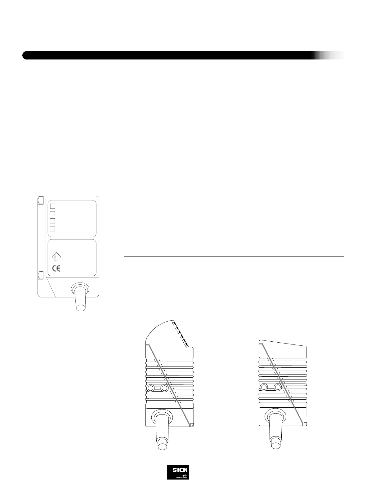
LED FUNCTIONALITY
There are four indicator LEDs on the CLV:
END OR SIDE SCANNING
The CLV 410/412 are available in a standard or a right angle version. This allows for
end scanning or side scanning.
Installation
8
SICK Optic-Electronic
Bar Code Scanners
2
SECTION II - INSTALLATION
Side Scanning
Device Ready
Result
Laser On
Data
End Scanning
Device Ready: Indicates that the scanner is powered and in the reading mode.
Result: Goes on or off (user-selectable) based on Good Read/Good Match or a No
Read/Wrong Read condition; default is Good Read.
Laser On: Indicates that a reading gate has been triggered and the laser is activated.
Data: Indicates that data is being transmitted to the host device via the host interface.
Page 11
9
SICK Optic-Electronic
Bar Code Scanners
2
Installation
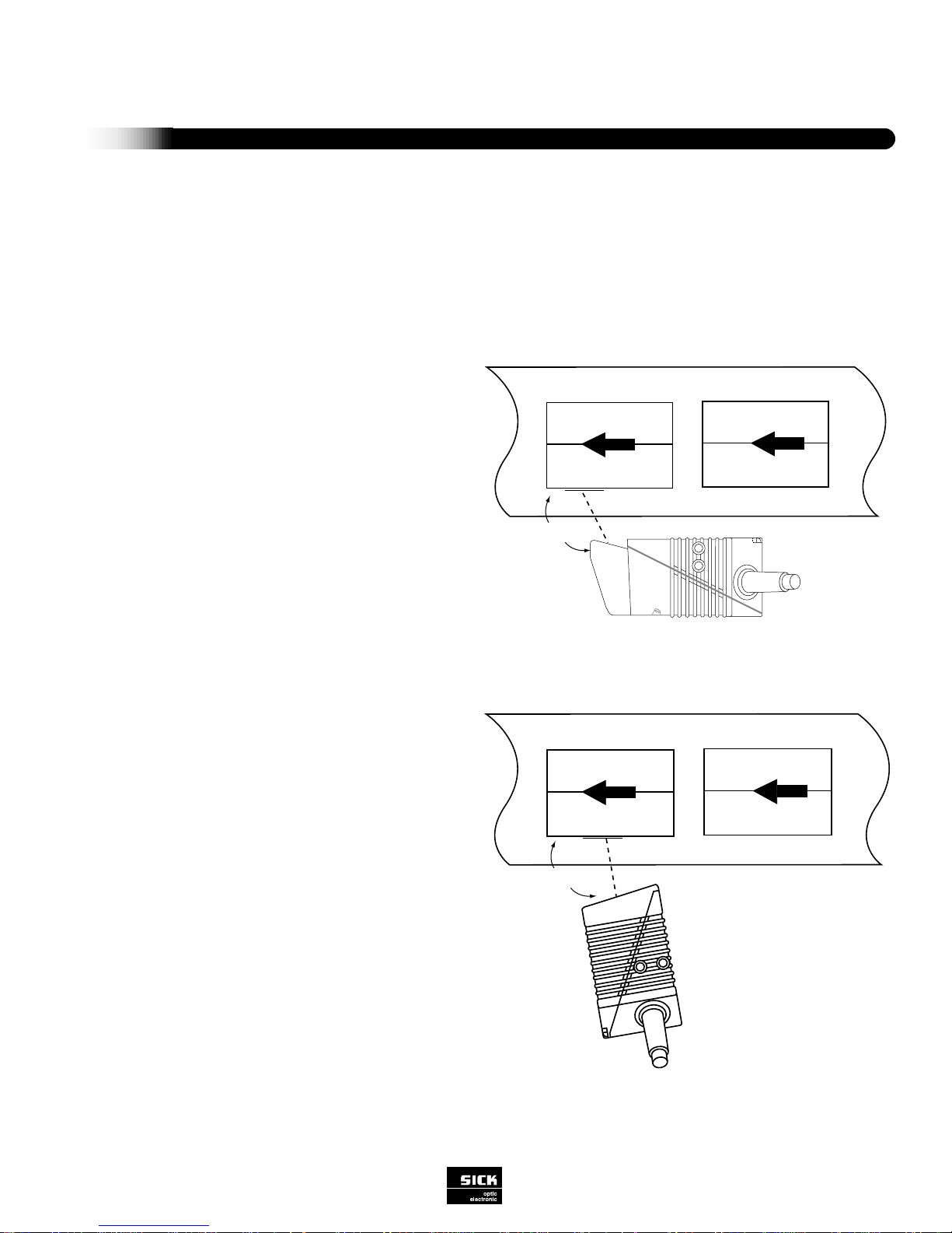
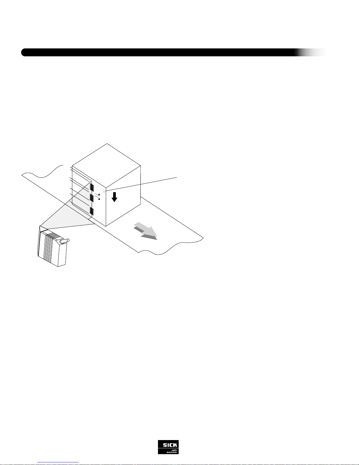
MOUNTING AND ALIGNMENT
The CLV should be mounted to permit alignment in three planes, with consideration for the bar code orientation on the conveyed
product. The CLV has two 5 mm (0.197 in) deep M4 tapped mounting holes located adjacent to the connectors.
Side Scanning
The illustration to the right shows the scanner in the side
scanning configuration. Simply mount the scanner with
the scanner body parallel to the surface to be read. The
position of the exit window provides the recommended 15
degree reading angle (skew angle) which reduces surface reflection.
End Scanning
The illustration shows the scanner in the end scanning
configuration. In order to reduce surface reflection, mount
the unit so that the body of the scanner is approximately
15 degrees from being perpendicular to the surface for
reading
105¡
105¡
Figure 2-1 Skew Angle for Side Scanning
Figure 2-2 Skew Angle for End Scanning
Page 12
Terminal
Host CLV
CLV 410
To Host Device for data transmission
(PLC, computer, etc.)
Installation
10
SICK Optic-Electronic
Bar Code Scanners
2
CONNECTORS AND PINOUTS
Make signal and power connections as explained below under “Power Supply Connections.” As a general precaution, shield all
lines carrying data and keep them as short as possible. Do not route them adjacent to other cables that could cause electromagnetic interference. CLV interface connections consist of a single 15-pin connector. Refer to Figure 2-3.
1
5
1611
10
Figure 2-3 CLV Interface Ports
(1) 24 V DC input for Teach Mode
(2) 24 V DC Output
(3) External Sensor input (24 V DC @
100mA) for trigger
Figure 2-4 PS 52 Power Supply Connectivity
1
2
3
4
5
6
7
8
9
10
11
12
13
14
15
-
DC +4.5...+30 V
Sensor 2
Result 3
Term RS 422
GND
RD+ (RS 422/485)
RD- (RS 422/485)
TD+ (RS 422/485)
TD- (RS 422/485)
RxD (RS 232)
TxD (RS 232)
Result 1
Result 2
Sensor 1
Sensor GND
-
Supply voltage
Switching input teach-in (match code 1)
Switching output (to PLC)
Termination for data interface 1
Ground
Data interface 1 (receiver)
Data interface 1 (receiver)
Data interface 1 (transmitter)
Data interface 1 (transmitter)
Data interface 2 (receiver)
Data interface 2 (transmitter)
Switching output (to PLC)
Switching output (to PLC)
Switching input for ext. reading pulse
Common ground (all inputs)
Shield
red
orange
green
yellow
black
pink
violet
white
gray
blue
brown
black/white
turquoise
red/white
brown/white
-
FunctionSignalPin
Wire colors
of cable
no. 6010137
6
Page 13
POWER SUPPLY CONNECTIONS
The CLV requires a power source of 5 V DC to 30 V DC. Current requirement for the CLV is 100 mA. Power supplies suitable
for the CLV include:
1. Power supply from SICK Optic-Electronic, Inc.
2. Another power supply provided by the customer. This power supply must meet the following specifications:
The 24 V DC output circuit must be isolated from the input circuit by double insulation and an isolating transformer. (Ref. IEC 742
and DIN / VDE 0551.)
Output voltage: 5 V DC ± 5% to 30 V DC ± 20%
Power output: minimum 15 VA
Current output: peak current maximum 1 A/continuous current minimum 500 mA
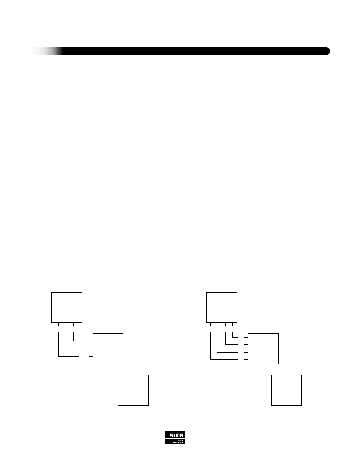
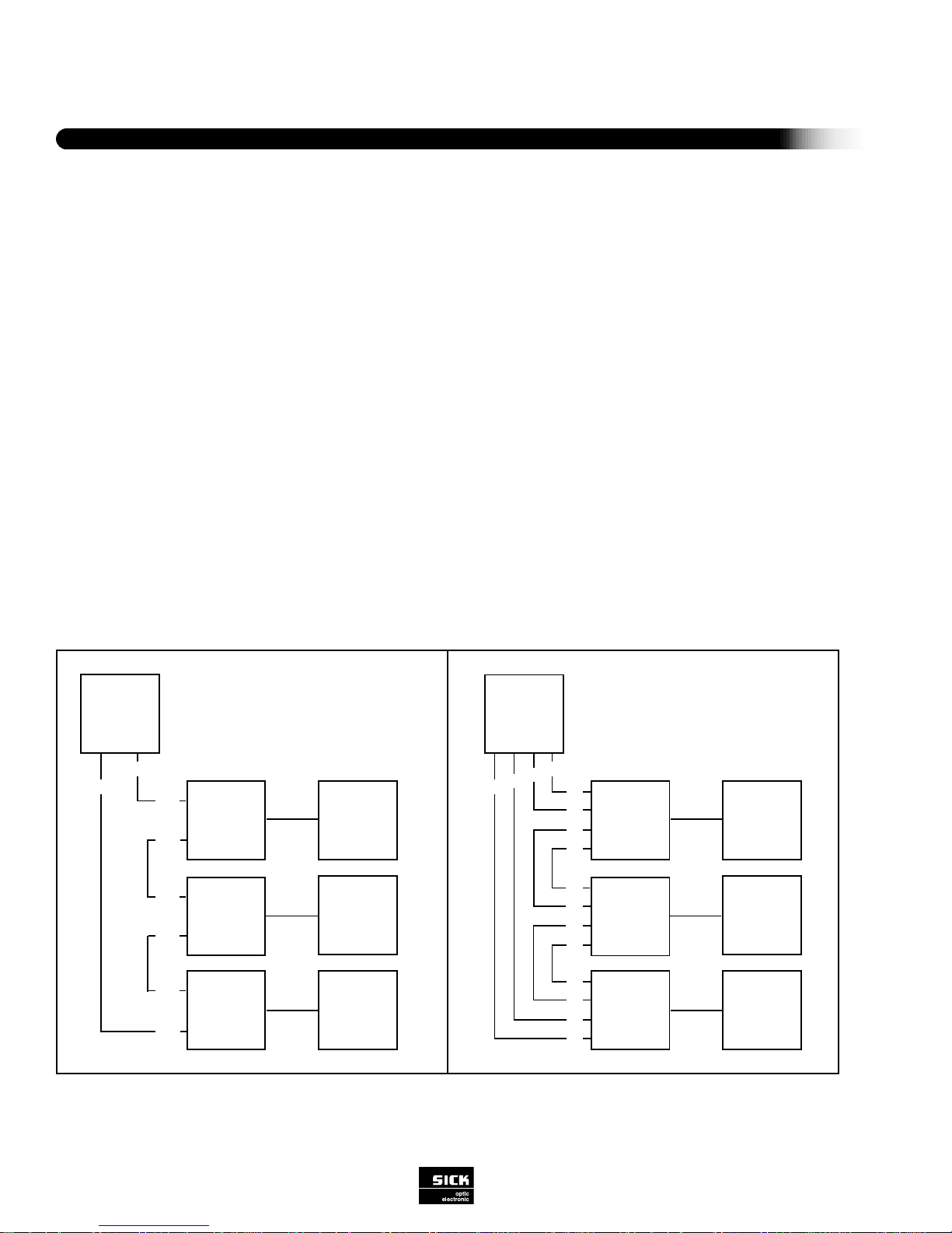
PHYSICAL CONFIGURATIONS OF SCANNERS
Host communication configurations include: point-to-point, daisy-chain (master/slave or pass-through), and network (RS 485
multidrop).
POINT-TO-POINT CONFIGURATIONS
In a point-to-point configuration, the CLV is connected directly to the host device via a power supply distribution unit. Figure 2-5
shows both of these point-to-point configurations. Functions include:
• Transmission of decoded bar code information from CLV to host
• Transfer of selected diagnostic reading data from CLV to host
• Relay of error strings from CLV to host
• Trigger of reading gate from host to CLV
• Programming and operation via command strings from host to CLV
11
SICK Optic-Electronic
Bar Code Scanners
2
Installation
Figure 2-5 Point-to-Point Configuration with RS 232 or RS 422 via Host Port
HOST DEVICE
DISTRIBUTION
UNIT
CLV
RxD TxD
RxD
TxD
HOST DEVICE
DISTRIBUTION
UNIT
CLV
T+ R-
T-
R+
T+
T-
R-
R+
RS 232
RS 422
Page 14
Installation
12
SICK Optic-Electronic
Bar Code Scanners
2
Figure 2-6 Daisy Chain Configuration via CLV Host Port
DAISY CHAIN CONFIGURATION
This configuration allows connection of several scanners to one interface port of the host device. There are two modes of operation in this configuration: master/slave or pass-through. There should be no more than 8 scanners used in these modes. Refer to
Figure 2-6 for an illustration of a daisy chain configuration.
Master/Slave Mode
For guidance in operating the scanners in the master/slave mode, refer to page 39.
Pass-Through Mode
In this mode of operation, the data from one scanner is passed to the next scanner in line and this is passed on again, etc. The
last scanner in line then transmits the data to the host device.
There is no time delay in this mode of operation, since each scanner provides a virtual connection.
The procedure required to activate this mode includes conditioning the output of each scanner to contain <STX>/“Data” <ETX>.
The “/” (forward slash) character is entered into the first position of the “Header” section.
The CLV uses the variable protocol framing <STX> and <ETX> characters which are selected in the Host Interface: Protocol sec-
tion. The forward slash is a special character to indicate the pass-through mode. Thus, the CLV receives the information and
immediately transmits the data to the host or to the next scanner in line.
2 Modes of Operation:
* Pass-Through Mode
* Master/Slave Mode
HOST DEVICE
DISTRIBUTION
UNIT
CLV
(master)
CLV
CLV
T-
R-
T-
R+
T+
T+
DISTRIBUTION
UNIT
T-
T+
R+
R-
DISTRIBUTION
UNIT
T-
T+
R+
R-
R-
R+
HOST DEVICE
DISTRIBUTION
UNIT
CLV
(master)
CLV
CLV
TxD
RxD
TxD
DISTRIBUTION
UNIT
TxD
RxD
DISTRIBUTION
UNIT
TxD
RxD
RxD
RS 232 RS 422
2 Modes of Operation:
* Pass-Through Mode
* Master/Slave Mode
Page 15
13
SICK Optic-Electronic
Bar Code Scanners
2
Installation
NETWORK CONFIGURATION
The CLV can be used as part of a multidrop network of bar code reading stations which communicate with a host device as
shown in Figure 2-6. Using an RS 485 bus consisting of a two-conductor cable, the system can address up to 31 devices. The
SICK CLX 200 Network Controller is used to organize data and control polling.
Figure 2-7 RS 485 Network Configuration via CLV Host Port
HOST DEVICE
DISTRIBUTION
UNIT
CLV
CLV
CLV
CLX 200
RS 422 or RS 232
R/T+
DISTRIBUTION
UNIT
DISTRIBUTION
UNIT
R/T-
R/T+
R/T-
R/T+
R/T-
Resistor Terminator
•
•
•
•
•
•
RS 485
RS 485
RS 485
RS 485
Page 16

To program the CLV scanner, activate the CLV Utility
Software and use the “Upload” icon to upload the contents
of the CLVscanner. Refer to figure 3-2. This procedure
displays the current settings of the CLVscanner and creates a working parameter file. Other options to create a
working file are to select “New” or “Open” on an existing file
saved to the disk. Once a working file has been created
you can make the necessary changes. After changes are
completed, use the “Download” icon to download the new
changes to the CLV scanner.
If you want the CLV scanner to retain the new changes
permanently in the EE prom, select “Permanent” when the
“Choose Download Options” box is displayed. Refer to
Figure 3-2. If you select “Temporary” the new changes will
be held in the CLV scanner’s RAM memeory.
Note: Since the CLV only has a single communications
interface there are certain parameters (baud rate, protocol
framing characters, network mode) which will prevent the
CLV from communicating with the CLV utility software. The
software will automatically determine baud rate and protocol framing characters. Use the icons
shown to the right or the “default” bar code to
establish communication. The Configuration
Profile default parameter bar code is included. Simply scan it to set communication defaults or
program the CLV within 5 seconds after power up as the
communication default are set temporarily.
Software Configurations
14
SICK Optic-Electronic
Bar Code Scanners
3
UPLOADING AND DOWNLOADING
This section describes the modes of CLV operation and includes an extensive discussion of parameterization, the process used
to configure the CLV to best accommodate your particular application.
The CLV can be programmed using the Windows-based CLV Utility Software (included) or a host device using the CLV Host
Command Language strings. This manual uses the CLV Utility Software as its basis.
MODES OF OPERATION
The CLV has two major modes of operation: the Reading Mode (entered automatically after power-up) and programming configuration mode. The programming/configuration options (Parameterization, Percent Evaluation, and Operating Data) are explained
in detail below.
Parameterization: Used to program the CLV scanner to best meet the demands of the desired application.
Percent evaluation: Continuous scanning mode that generates statistical information used mainly for alignment and adjustment
(optimal beam position) when installing the CLV.
Operating data: Used for polling and resetting internal operating data of the CLV. The submenu of this operating mode is
explained following “Percent Evaluation”
Download Button
Upload Button
Figure 3-2 Download Saving Options
Figure 3-1 Download / Upload Options Selection
SECTION lll SOFTWARE CONFIGURATION
Page 17

15
SICK Optic-Electronic
Bar Code Scanners
3
Software Configurations
Figure 3-1 Code Configuration
CODE CONFIGURATION
This function is used to program the scanner to accept certain types and numbers of bar codes. The default settings for code
configuration can be referenced in Appendix B, Table 1. To activate/deactivate individual sybologies click on the respective check
box.
Note: To edit individual symbologies, select the “Edit codes” bar.
Page 18
10
0
5
25
35
55
70
80
100
SCAN
DIRECTION
CODE POSITION
MINIMUM DISTANCE BETWEEN LABELS
Software Configurations
16
SICK Optic-Electronic
Bar Code Scanners
3
Figure 3-4 Determining Code Position
Numeric Symbologies:
•Interleaved 2/5
•UPC version A/E (standard/with add-on)
•EAN 13/8-digit (standard/with add-on)
•Pharmacode
Alphanumeric Symbologies:
•Code 39 (standard full ASCII)
•Code 93 (standard full ASCII)
•Code 128
•Codabar
•EAN 128
Each type of bar code is introduced below with
a brief explanation of the composition of the
code. In one reading gate, up to ten bar code
labels (up to ten different symbologies) can be
decoded. The bar codes may appear simultaneously in a single scan or consecutively during
the reading gate.
The CLV is capable of reading and evaluating the following bar code symbologies:
Number of Codes
Minimum (1-10) (Minimum Number of Codes)
If more than one code is to be read in a reading gate, the minimum number of codes (1-10) that will be presented to the scanner
during the reading gate must be entered. If, at the end of the reading gate, the minimum number of bar codes were not decoded
and if the error status valve is activated, the CLV sends the data and an error status code (ST=2).
Maximum (1-10) (Maximum Number of Codes)
The maximum number of codes (1-10) that will be presented to the scanner during the reading gate must be entered. The CLV
will transmit only the number of bar codes specified here, even if the actual number of codes presented to it exceed this value. At
the very least, maximum = minimum number of codes.
Code Position (Compare/Minimum Distance of Labels)
The CLV performs code position comparison, i.e. the scanner recognizes the position of bar codes in order to identify whether
identical readings are a result of the same or different bar code labels. The CLV scanner breaks the scan line into 100 units
referred to as “code positions” (Figure 3-3). If CP-Comp. Multir. is activated, the CLV will determine the bar code position for each
read. If the bar code positions differ more than the “minimum distance between labels” setting, the scanner will acknowledge multiple labels. Valid range for the “minimum distance between labels” parameter is 0.4 in to 39 in (10 mm to 999 mm).
Page 19
17
SICK Optic-Electronic Bar Code Scanners
3
Software Configurations
Code Length (free/interval/fixed)
The scanner can be programmed to read bar codes of any length or only those of a particular length (entered by the user):
“free” - Bar codes of any length between 1 and 49 characters will be read.
“interval” - User may enter a range of lengths within which the scanner will read the codes. Valid entries are from 1 to 49.
“fixed” - User may program up to five different fixed lengths to be read by the scanner. Valid entries are from 1 to 49.
Code length for Code 39 is calculated as follows:
number of bars – 10
Code Length = –––––––––––––––––––––
5
Multiple Reads (1-99)
Enter the number of identical reads the scanner must decode (in one reading gate) before transmitting the result to the host
device. This process increases output reliability. The selected scanning frequency and the speed at which the bar code is moving
past the CLV should be considered when making this selection. If the number of multiple reads specified by the user is not fulfilled, the CLV will send the bar code string or error string (software selectable) to the host along with the error status ST=5, if the
ST value has been placed in the separator.
Check Digit Test
For printed bar codes with an integrated check digit in the useful characters (last position before stop character), the check digit
increases error detection and therefore reading reliability. With a “yes” response, the decoder activates a routine to compare the
printed check digit with the check digit being calculated. The decoder then outputs the bar code data with the error status as follows: If the check digit test is successful, ST=0 (good read); if the check digit test is not successful, ST=1 (wrong check digit).
The error status is output only if the error status value is activated as part of the data string. If the user responds here with a “no,”
no check digit test will be carried out.
Transmit Check Digit
A “yes” allows the check digit to be transmitted to the host device. With a “no” response, the check digit is not transmitted.
Note: The CLV automatically truncates the last digit of the data if “no” to transmit check digit is selected.
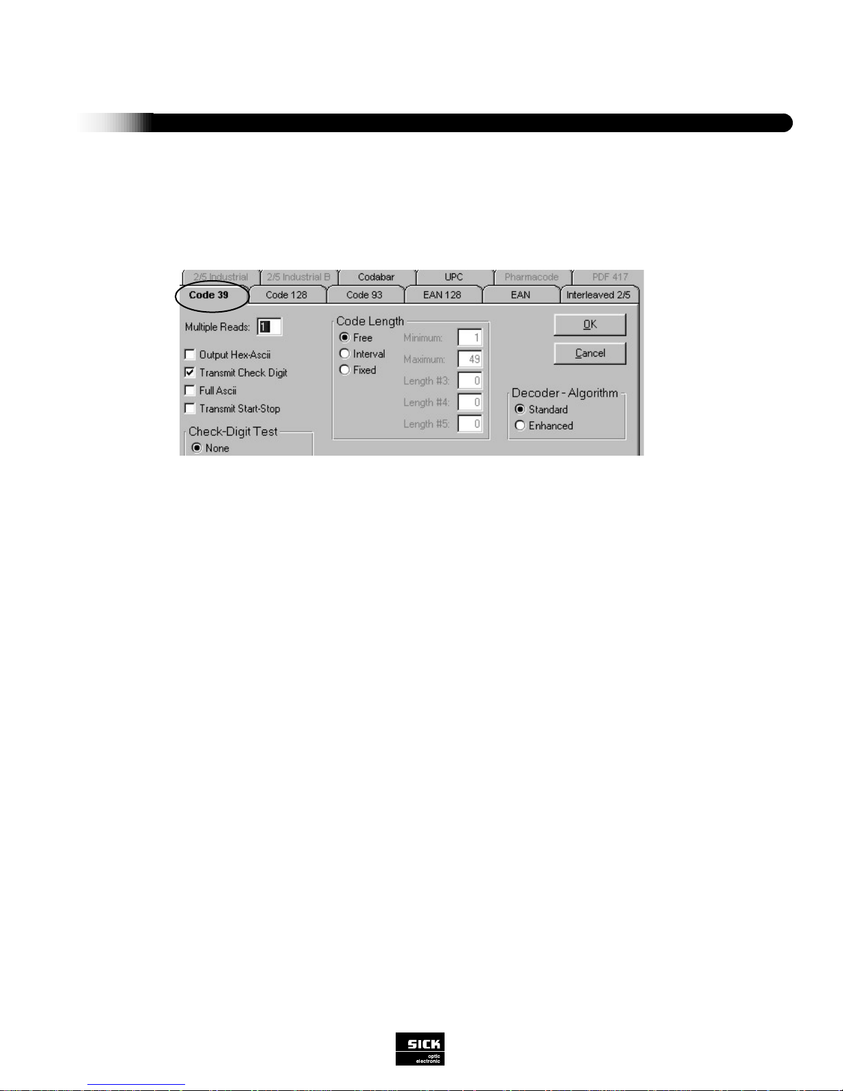
CODE 39 (Code 3 of 9)
An alphanumeric code using the following character set:
10 numbers (0 to 9); 26 capital letters (A-Z); 7 special characters; and one start/stop character.
Figure 3-5 Code 39
Page 20
Software Configurations
18
SICK Optic-Electronic
Bar Code Scanners
3
Transmit Star t/Stop Character
A “yes” allows the start and stop characters to be transmitted to the host device. With a “no” response, the start and stop characters are not transmitted.
Full ASCII
A “yes” selects Full ASCII, which directs the decoder to evaluate the existing code as an extended Code 39. With a “no”
response, the existing code is evaluated and output as a standard Code 39.
Output Hex ASCII
A “yes” directs the decoder to output the code content in hex ASCII format. With a “no” response, ASCII output format is used.
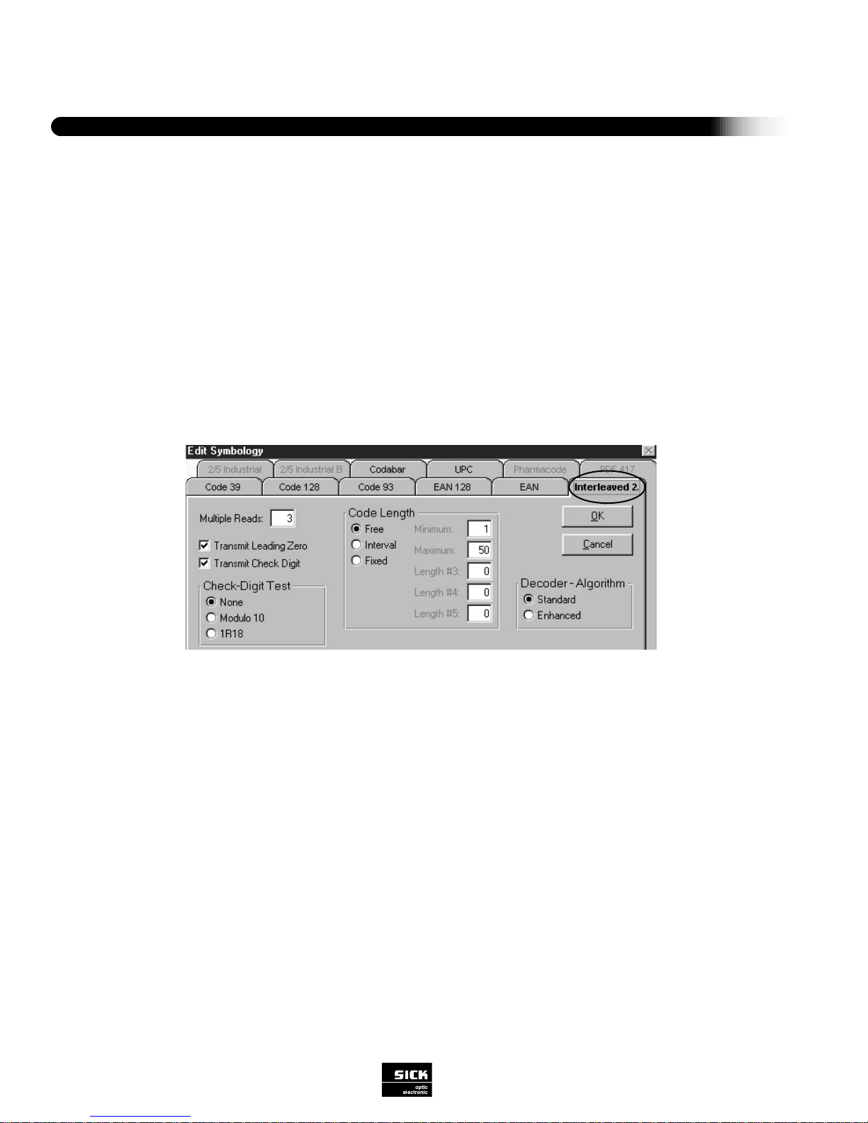
INTERLEAVED 2/5 (Interleaved 2 of 5)
A numerical code with the following character set: 10 digits (0 to 9); one start character; one stop character.
Figure 3-6 Interleaved 2/5
Code Length (free/interval/fixed)
The scanner can be programmed to read bar codes of any length or only those of a particular length (entered by the user):
“free” - Bar codes of any length between 1 and 49 characters will be read.
“interval” - User may enter a range of lengths within which the scanner will read the codes. Valid value 1 to 49.
“fixed” - User may program up to five different fixed lengths to be read by the scanner. Valid value 1 to 49.
Code length for Interleaved 2/5 includes the number of useful characters plus the check digit and is determined from the total
number of wide elements (bars or gaps) as follows:
(wide elements – 1)
Code Length = ––––––––––––––––––––
2
Multiple Reads (1-99)
Enter the number of identical reads the scanner must decode (in one reading gate) before transmitting the result to the host
device. This process increases output reliability. The selected scanning frequency and the speed at which the bar code is moving
past the CLV should be considered when making this selection. If the number of multiple reads specified by the user is not fulfilled, the CLV will send the bar code string or error string (software selectable) to the host, along with the error status ST=5 if the
ST value has been placed in the separator.
Page 21

19
SICK Optic-Electronic
Bar Code Scanners
3
Software Configurations
Check Digit Test
For printed bar codes with an integrated check digit in the useful characters (last position before stop character), the check digit
increases error detection and therefore reading reliability. With a “yes” response, the decoder activates a routine to compare the
printed check digit with the check digit being calculated. The decoder then outputs the bar code data with the error status as follows: If the check digit test is successful, ST=0 (good read); if the check digit test is not successful, ST=1 (wrong check digit).
The error status is output only if the error status value is activated as part of the data string. If the user responds here with a “no,”
no check digit test will be carried out.
Transmit Check Digit
A “yes” allows the check digit to be transmitted to the host device. With a “no” response, the check digit is not transmitted.
Note: The CLV automatically truncates the last digit of the data if “no” to transmit check digit is selected.
Transmit Leading Zero
Individual characters in the code overlap so that digits can be represented in pairs only. If the code is made up of an odd digit
sequence (useful characters), it is filled out with a leading zero. With a “yes” response, the zero is included in the output. With a
“no” response, the zero is suppressed.
EAN (European Article Numbering)
A numerical code with the following character set: 10 digits (0 to 9 per bar code character set), one edge character, one dividing
character.
Figure 3-7 EAN (European Article Numbering)
13-Digit
Code length of 13 digits.
8-Digit
Code length of 8 digits.
With Add-on (none/2 digit/5-digit/both)
The add-on is an additional bar code of two or five digits that follows the 8 or 13 digits of the EAN. Selectable commands are:
none =Add-on is not evaluated
2-digit =Evaluate and output 2-digit add-on
5-digit =Evaluate and output 5-digit add-on
both =Evaluate and output 2-digit AND 5-digit add-on
Page 22
Software Configurations
20
SICK Optic-Electronic
Bar Code Scanners
3
Multiple Reads (1-99)
Enter the number of identical reads the scanner must decode (in one reading gate) before transmitting the result to the host
device. This process increases output reliability. The selected scanning frequency and the speed at which the bar code is moving
past the CLV should be considered when making this selection. If the number of multiple reads specified by the user is not fulfilled, the CLV will send the bar code string or error string (software selectable) to the host along with the error status ST=5, if the
ST value has been placed in the separator.
Transmit Check Digit
A “yes” allows the check digit to be transmitted to the host device. With a “no” response, the check digit is not transmitted.
Note: The CLV automatically truncates the last digit of the data if “no” to transmit check digit is selected.
Decoding Algorithm (enhanced/standard)
Selecting “enhanced” will direct the CLV to use a 2-step decoding process; “standard” executes a rapid, 1-step decoding process.
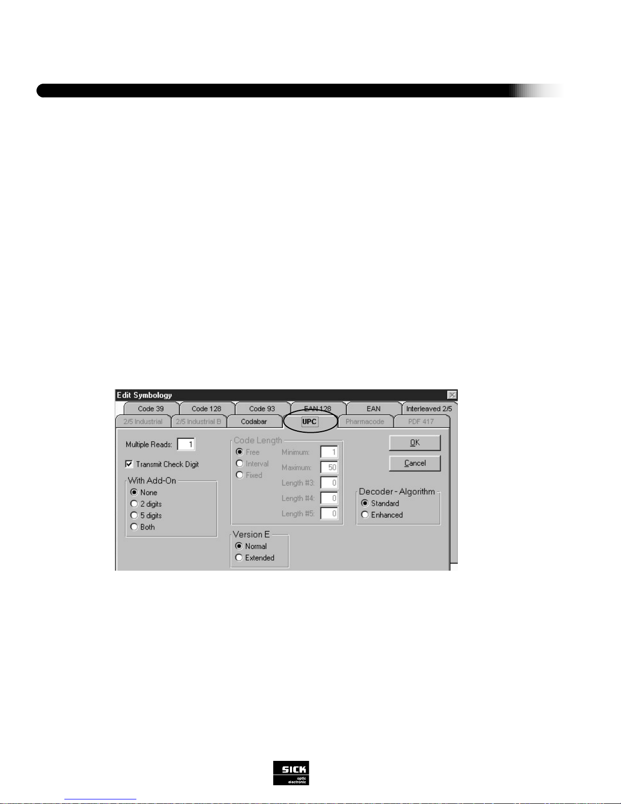
UPC (Universal Product Code)
A numerical code with two versions, A and E. The character set for Version A is: 10 digits (0 to 9); the number system character;
the module check character. The character set for Version E is: 6 digits (0 to 9).
Figure 3-8 UPC Selection
Code Length: UPC-A: 12-digit (normal version)
UPC-E: 6-digit (short version)
Each contains a check digit.
With Add-on (none/2 digit/5-digit/both)
The add-on is an additional bar code of two or five digits that follows the digits of version Aor E code. Selectable commands are:
none = Add-on is not evaluated
2-digit = Evaluate and output 2-digit add-on
5-digit = Evaluate and output 5-digit add-on
both = Evaluate and output 2-digit AND 5-digit add-on
Page 23
21
SICK Optic-Electronic
Bar Code Scanners
3
Software Configurations
Multiple Reads (1-99)
Enter the number of identical reads the scanner must decode (in one reading gate) before transmitting the result to the host
device. This process increases output reliability. The selected scanning frequency and the speed at which the bar code is moving
past the CLV should be considered when making this selection. If the number of multiple reads specified by the user is not fulfilled, the CLV will send the bar code string or error string (software selectable) to the host along with the error status ST=5, if the
ST value has been placed in the separator.
Transmit Check Digit
A “yes” allows the check digit to be transmitted to the host device. With a “no” response, the check digit is not transmitted.
Note: The CLV automatically truncates the last digit of the data if “no” to transmit check digit is selected.
Decoding Algorithm (enhanced/standard)
Selecting “enhanced” will direct the CLV to use a 2-step decoding process; “standard” executes a rapid, 1-step decoding process.
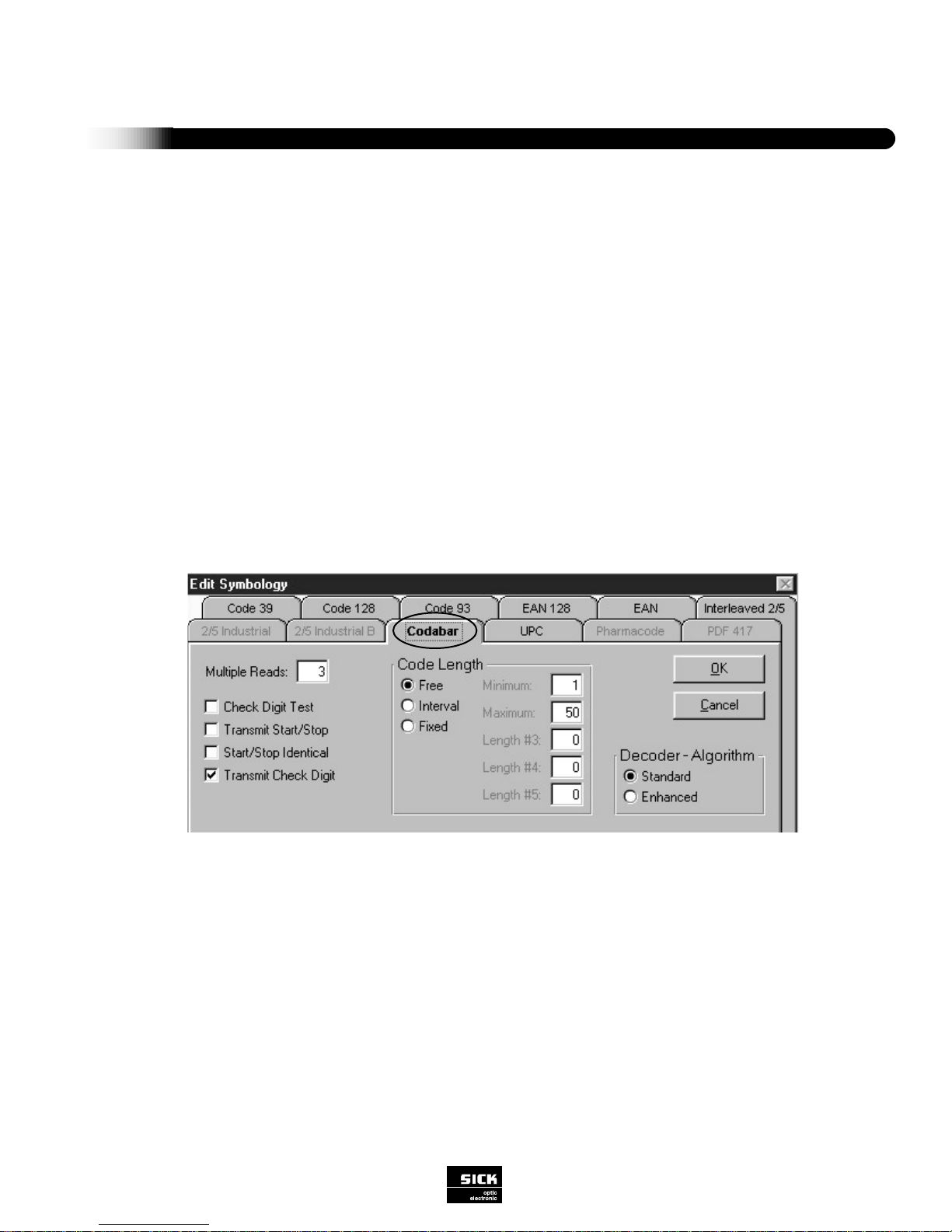
CODABAR
An alphanumeric code with the following character set: 10 digits (0 to 9); six special characters; four start/stop characters.
Figure 3-9 Codabar
Code Length (free/interval/fixed)
The scanner can be programmed to read bar codes of any length or only those of a particular length (entered by the user):
“free” - Bar codes of any length between 1 and 50 characters will be read.
“interval” - User may enter a range of lengths within which the scanner will read the codes.
“fixed” - User may program up to five different fixed lengths to be read.
The code length of the printed bar code, including the useful characters plus check digit, can be determined from the number of
wide bars as follows:
(number of bars - 8)
Code Length = –––––––––––––––––––––
4
Page 24
Multiple Reads (1-99)
Enter the number of identical reads the scanner must decode (in one reading gate) before transmitting the result to the host
device. This process increases output reliability. The selected scanning frequency and the speed at which the bar code is moving
past the CLV should be considered when making this selection. If the number of multiple reads specified by the user is not fulfilled, the CLV will send the bar code string or error string (software selectable) to the host along with the error status ST=5, if the
ST value has been placed in the separator.
Check Digit Test
For printed bar codes with an integrated check digit in the useful characters (last position before stop character), the check digit
increases error detection and therefore reading reliability. With a “yes” response, the decoder activates a routine to compare the
printed check digit with the check digit being calculated. The decoder then outputs the bar code data with the error status as follows: If the check digit test is successful, ST=0 (good read); if the check digit test is not successful, ST=1 (wrong check digit).
The error status is output only if the error status value is activated as part of the data string. If the user responds here with a “no,”
no check digit test will be carried out.
Transmit Check Digit
A “yes” allows the check digit to be transmitted to the host device. With a “no” response, the check digit is not transmitted.
Note: The CLV automatically truncates the last digit of the data if “no” to transmit check digit is selected.
Transmit Star t/Stop
A “yes” response directs the decoder to output information with start/stop characters “a,” “b,” “c” or “d,” together with useful char-
acters. A“no” response suppresses the output of start/stop characters.
Identical Start/Stop
A “yes” response directs the decoder to output only printed bar codes having the same start and stop characters. A “no” response
allows any combination of start and stop characters to be output.
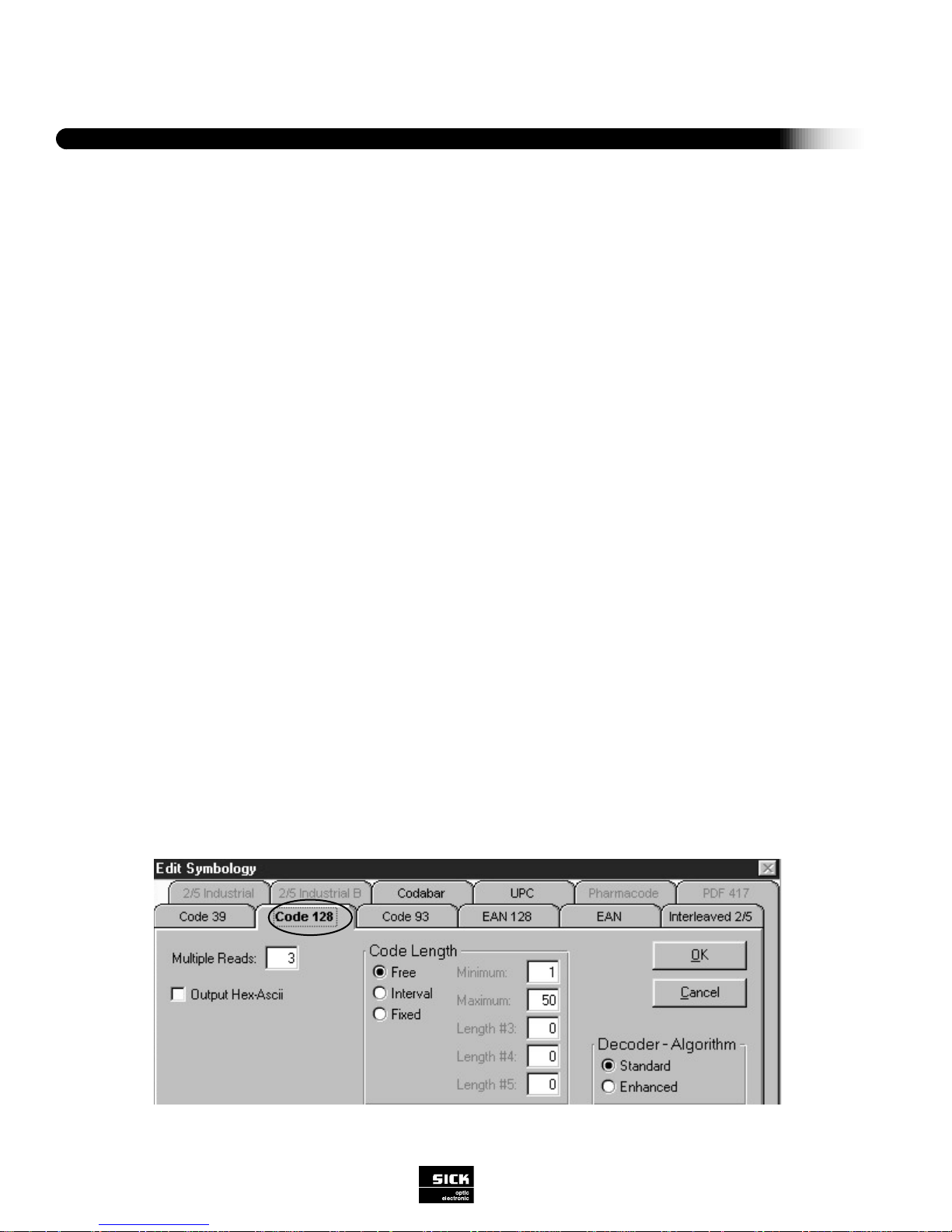
CODE 128
An alphanumeric code with the following character set: 128 ASCII characters; four special characters; four control characters;
three start characters; one stop character. Character sets A, B, or C can be represented (these character sets can be referenced
in the Uniform Symbology Specification).
A check digit test is always performed, but does not print out.
Software Configurations
22
SICK Optic-Electronic
Bar Code Scanners
3
Figure 3-10 Code 128
Page 25

23
SICK Optic-Electronic
Bar Code Scanners
3
Software Configurations
Code Length (free/interval/fixed)
The scanner can be programmed to read bar codes of any length or only those of a particular length to be entered by the user:
“free” - Bar codes of any length between 1 and 49 characters will be read.
“interval” - User may enter a range of lengths within which the scanner will read the codes. Valid Values 1 to 49.
“fixed” - User may program up to five different fixed lengths to be read by the scanner. Valid Values 1 to 49.
The code length of a printed bar code is calculated as follows:
(number of bars - 7)
Code Length = –––––––––––––––––––––
3
The code length must be input without start/stop characters and without a check digit.
Multiple Reads (1-99)
Enter the number of identical reads the scanner must decode (in one reading gate) before transmitting the result to the host
device. This process increases output reliability. The selected scanning frequency and the speed at which the bar code is moving
past the CLV should be considered when making this selection. If the number of multiple reads specified by the user is not fulfilled, the CLV will send the bar code string or error string (software selectable) to the host along with the error status ST=5, if the
ST value has been placed in the separator.
Output Hex ASCII
A “yes” directs the decoder to output in hex ASCII. A “no” response directs the decoder to output in ASCII.
Decoding Algorithm (enhanced/standard)
Selecting “enhanced” will direct the CLV to use a 2-step decoding process; “standard” executes a rapid, 1-step decoding process.
Page 26

Software Configurations
24
SICK Optic-Electronic
Bar Code Scanners
3
Figure 3-11 Code 93
Code Length (free/interval/fixed)
The scanner can be programmed to read bar codes of any length or only those of a particular length (entered by the user):
“free” - Bar codes of any length between 1 and 49 characters will be read.
“interval” - User may enter a range of lengths within which the scanner will read the codes. Valid Values 1 to 49.
“fixed” - User may program up to five different fixed lengths to be read by the scanner. Valid Values 1 to 49.
The code length of a printed bar code is calculated as follows:
(number of bars - 7)
Code Length = –––––––––––––––––––––
3
The code length must be input without start/stop characters and without a check digit.
Multiple Reads (1-99)
Enter the number of identical reads the scanner must decode (in one reading gate) before transmitting the result to the host
device. This process increases output reliability. The selected scanning frequency and the speed at which the bar code is moving
past the CLV should be considered when making this selection. If the number of multiple reads specified by the user is not fulfilled, the CLV will send the bar code string or error string (software selectable) to the host, along with the error status ST=5 if the
ST value has been placed in the separator.
Output Hex ASCII
A “yes” directs the decoder to output in hex ASCII. A “no” response directs the decoder to output in ASCII.
Decoding Algorithm (enhanced/standard)
Selecting “enhanced” will direct the CLV to use a 2-step decoding process; “standard” executes a rapid, 1-step decoding process.
CODE 93
An extended alphanumeric code with the following character set: 128 characters (complete ASCII character set); one start/stop
character. A check digit test is always performed, but not output.
Page 27

25
SICK Optic-Electronic
Bar Code Scanners
3
Software Configurations
Code Length (free/interval/fixed)
The scanner can be programmed to read bar codes of any length or only those of a particular length (entered by the user):
“free” - Bar codes of any length between 1 and 49 characters will be read.
“interval” - User may enter a range of lengths within which the scanner will read the codes. Valid values – 1 to 49.
“fixed” - User may program up to five different fixed lengths to be read by the scanner. Valid values – 1 to 49.
The code length of a printed bar code is calculated as follows:
(number of bars - 7)
Code Length = –––––––––––––––––––––
3
The code length must be input without start/stop characters and without a check digit.
Multiple Reads (1-99)
Enter the number of identical reads the scanner must decode (in one reading gate) before transmitting the result to the host
device. This process increases output reliability. The selected scanning frequency and the speed at which the bar code is moving
past the CLV should be considered when making this selection. If the number of multiple reads specified by the user is not fulfilled, the CLV will send the bar code string or error string (software selectable) to the host along with the error status ST=5, if the
ST value has been placed in the separator.
Output Hex ASCII
A “yes” directs the decoder to output in hex ASCII. A “no” response directs the decoder to output in ASCII.
Figure 3-12 EAN 128
EAN 128 (European Article Numbering 128)
A fixed-length numeric code. A check digit test is always performed, but does not print out.
Page 28

Note: If selected, all other symbologies will be automatically deactivated.
Code Length (fixed code length 0-16)
The user can program one fixed length to read by the scanner. Valid entries are from 0 to 16. Default is 4.
Multiple Reads (1-99)
Enter the number of identical reads the scanner must decode (in one reading gate) before transmitting the result to the host
device. This process increases output reliability. The selected scanning frequency and the speed at which the bar code is moving
past the CLV should be considered when making this selection. If the number of multiple reads specified by the user is not fulfilled, the CLV will send the bar code string or error string (software selectable) to the host along with the error status ST=5.
Module Width (auto/.50 mm/.33 mm)
The module width refers to the width of the bar elements of the code. “Auto” is selected for a pharmacode label that has a combination of wide and narrow bar elements (1’s & 0’s). “.50” or “.33” are selected when the bar elements of the pharmacode label
are all the same (all 1’s or 0’s). In the later case, the use is required to select the one that best represents the bar element width
of the pharmacode label..
Direction (forward/reverse)
Since pharmacode does not have start and stop characters, the scanning direction will affect the data set order. If “forward” is
selected, the scanner will transmit the data set according to the scan direction. If “reverse” is selected, the scanner will transmit
the data set in reverse order of the scanning direction. This feature is very useful when the orientation of the label changes and
the scanner can accommodate this change without physically rotating the scanner.
Software Configurations
26
SICK Optic-Electronic
Bar Code Scanners
3
Figure 3-13 Pharmacode
Interpret FC1 (FC1 First Char ...... 3 values/FC1 in Code String ...... 3 values)
FC1 (Function Character 1) is a special character in the bar code label which carries out a certain function. In place of this FC1
value, the decoder inserts a sequence of up to 3 user-definable characters in the output string (exceptions are 06 hex, 11 hex, 13
hex, 15 hex, in addition to stop and start characters). The FC1 can be placed at the beginning of the data string or somewhere
within the data string.
Decoding Algorithm (enhanced/standard)
Selecting “enhanced” will direct the CLV to use a 2-step decoding process; “standard” executes a rapid, 1-step decoding process.
PHARMACODE
Pharmacode is one of the oldest bar codes. It is used primarily in the pharmaceutical packaging industry. Pharmacode is a
numeric code which consists of two element sizes - wide or narrow. The wide bar represent a “1”, and the narrow bar indicates a
“0”. There are no start and stop characters associated with the pharmacode. Thus, depending on the scan direction, different data
sets may occur. Also, since there are no start and stop characters, adequate quiet zone is required.
Page 29

27
SICK Optic-Electronic
Bar Code Scanners
3
Software Configurations
READING CONFIGURATION
This function allows the user to program the CLV to read at selectable frequencies and select the appropriate minimum bar width
of the bar code to be read.
Fig. 3-14 Reading Configuration
Custom Settings (Minimum Bar Width/Minimum Distance/Scanning Frequency)
Minimum Bar Width ...... mm (millimeters)
Minimum bar width is adjustable in steps of 0.004 in (0.01 mm). This refers to the X-dimension (narrowest bar element width), of
the bar code. Set the scanner accordingly. The valid range is listed below..
default
CLV 410 .008 in to .040 in (.2 mm to 1.0 mm) .008 in (.20 mm)
CLV 412 .004 in to .008 in (.1 m to .2 m) .008 in (.20 mm)
Minimum Distance
This represents the closest distance from the scanner that the object will need to be scanned. Valid range listed below in 1 mm
(.04") increments:
default
CLV 410/412 .80 in to 16 in (20 mm to 400 mm) 1.0 in (25 mm)
Page 30

“Ladder” Orientation Equation
Scan Frequency = (V x N) Number of Scans = H
––––––– –––– x SF
HV
“Picket Fence” Orientation Equation
Scan Frequency = (V x N) Number of Scans = (W - L) x SF
––––––– ––––––––––––
W-L V
Following is an example for calculating scan frequency for a bar code in “ladder” orientation:
- Conveyor speed (V) = 100 ft/min = 20 in/sec
- Bar height (H) = .5 in
- Printed bar code 100% readable (material, printing, surface)
- Optimal adjustment of CLV (reading distance, angle, resolution)
- Required scans per code (N) = 10
20 x 10
SF= ——–——-
0.5
SF= 400 Hz
10 to 15 scans per code is usually sufficient. Any further increase does not produce better reading results. However, slower scan
rates can help the scanner read codes that are harder to read. Some causes for this reduction are: a dusty lens on the CLV,
small minimum width of the bar code, or bar code quality (i.e. poor print contrast).
Code Position Read Zone
This function allows the user to create an electronic mask. The scan line of the scanner is divided into 100 positions called Code
Position (CP) values. By entering minimum and maximum CP values, you effectively create a reading zone within the scan line.
This is very useful when the spacing of the objects to be scanned is small. The valid choices are 0 to 100 in 1 value increments:
Minimum CP ...... 0 to 100 default 0
Maximum CP ...... 0 to 100 default 100
Software Configurations
28
SICK Optic-Electronic
Bar Code Scanners
3
= Scan frequency
= Label velocity (inches/second)
= Number of scans required
= Bar height
= Scan width
= Label length
SF
V
N
H
W
L
The following variables and
equations are valid:
Scan Frequency
Sets the scan rate of the scanner, from 200 to 800 Hz, in 50 Hz increments. The conveyor speed and the scanning frequency of
the CLV determine the number of reads theoretically possible per bar code. The higher the scanning frequency, the greater the
number of scans possible as the bar code passes the scanner (assuming a constant conveyor speed). With this information, a
large number of scans can be checked for agreement of information content. This increases reading reliability. The variable scanning frequency thus enables the reading process to be optimally matched to the conveyor speed and the number of multiple
reads required. See following page for valid variable examples.
Page 31

29
SICK Optic-Electronic
Bar Code Scanners
3
Software Configurations
CLV 410 / 412 Test Conditions
O
60
20
O
CLV
20
O
O
60
Test Code
Print Ratio
Code Print Contrast
Scan Frequency
(0.1...0.2 mm Code
Skew
Tilt
Ambient Light
Good Read Rate
Code 39/ITF
3:1
>90%
200...250 Hz
200 Hz)
15°
±10°
<2000 lx
>75%
Test Conditions
Figure 3-15 Reading Distance Test Conditions
Page 32

Software Configurations
30
SICK Optic-Electronic
Bar Code Scanners
3
CLV 410
200 (7.8)
150 (5.9)
100 (3.9)
50 (1.9)
0
200 (7.8)
150 (5.9)
100 (3.9)
50 (1.9)
0.2 m
.35 mm
.50 mm
1.0 m
(.008 in)
(.014 in)
(.020 in)
(.040 in)
200
(7.8)
150
(5.9)
100
(3.9)
50
(1.9)
250
(9.8)
300
(11.7)
350
(13.7)
400
(15.6)
0
CLV 410 / 412
Dimensions in mm (in)
Subtract 18 mm from reading range if angled hood is used.
Dimensions in mm(in)
Reading Distance
Scan Frequency (Hz)
Dimensions in mm(in)
Subtract 18 mm from reading range if angled hood is used.
Page 33

print ratio: 2:1
60
40
20
0
-20
-40
-60
0604020 80 100 120
(.008 in)
(2.4)
(1.6)
(.80)
(-.80)
(-1.6)
(-2.4)
(2.4)(1.6)(.80) (3.2) (4.0) (4.8)
.20 mm
31
SICK Optic-Electronic
Bar Code Scanners
3
Software Configurations
CLV 410 Close Range Version
Reading distance mm(in)
Reading distance mm(in)
Subtract 18 mm from reading range if angled hood is used.
Page 34

Software Configurations
32
SICK Optic-Electronic
Bar Code Scanners
3
CLV 412 High Density
1000
900
800
700
600
500
400
300
200
100
0
0 10 20 30 40 50 60 70 80 90 100
(39.0)
(35.1)
(31.2)
(27.3)
(23.4)
(19.5)
(15.6)
(11.7)
(7.8)
(3.9)
(.40) (.80) (.12) (.16) (2.0) (2.4) (2.8) (3.1) (3.5) (3.9)
0.1 mm (.004)
0.12 mm (.005)
0.15 mm (.006)
0.2 mm (.008)
60 (2.4)
45 (1.8)
30 (1.2)
15 (.6)
0
0.2 m
.35 mm
.50 mm
1.0 m
35
(1.4)
0
75 (3.0)
45
(1.8)
55
(2.2)
65
(2.6)
75
(3.0)
85
(3.4)
15
(0.6)
25
(1.0)
-60 (2.4)
-45 (-1.8)
-30 (-1.2)
-15 (-3.0)
-75 (3.0)
.20 mm
(.008 in)
.15 mm
(.006 in)
.1 mm
(.004 in)
95
(3.8)
Scan Frequency (Hz)
Reading distance mm/(in)
Reading distance mm(in)
Reading distance mm(in)
Page 35

33
SICK Optic-Electronic
Bar Code Scanners
3
Software Configurations
Segmentation (Start/Stop Ratio/Absolute Quiet Zone)
This allows the user to adapt the CLV to the quiet zone of the bar code label if it is less than the specified 10 times the width of
the narrowest bar element or less than .250 in (6 mm).
“Start/Stop Ratio”
The start/stop ratio refers to the quiet zones of the bar code label. The scanner can be optimized for the appropriate width of the
quiet zones. The numerical values 4-11 are multiples of the minimum bar width. “Auto” is 10 times the width of the minimum bar
width.
“Absolute Quiet Zone”
This refers to the quiet zones of the bar code label. The CLV can be optimized for the appropriate width of the quiet zones. The
numerical value, .004 in to 1 in (1 mm to 25.5 mm), corresponds directly to the actual width of the quiet zone.
Note: This function relies on the Minimum Reading Distance, such that the Minimum Reading Distance setting has to reflect the
actual distance from the face of the CLV to the bar code label. If the Minimum Reading Distance setting is not set accordingly, the
CLV will not be able to read the label. Therefore, a small or-no-depth of field can be achieved by the CLV in this mode.
Figure 3-16 Device Configuration
DEVICE CONFIGURATION
This function allows you to program the CLV mechanical features and the CLV decoder to provide selected output data. See
Appendix B, Tables 2 and 3 for default settings for these parameters.
Page 36

Software Configurations
34
SICK Optic-Electronic
Bar Code Scanners
3
CLOCK PULSE
The reading gate is initiated by a clock pulse (trigger device), which synchronizes the scanning process with the occurrence of a
printed bar code in the field of view. The CLV accepts these different trigger sources: an external clock pulse generator (hardware
trigger), [host device command strings (serial interface)], [internal clock pulse generation (free-running)] and reflector polling (use
of a special bar code for automatic triggering). The different trigger sources are shown in Figure 3-19.
Source Clock Pulse
Select one of the following options to configure the source of the clock pulse:
“Sensor Input”(active high), is selected if the clock pulse originates from a switching
input such as a photoelectric device. “Sensor Input” (active low) is selected when the
sensor input is high (+24 V DC, PNP) and brings it to 0 V DC when something is
detected, or low (0 V DC) and switches to high (+24 V DC, PNP) when something is
detected. [“Active High”, which holds the sensor input low (0 V DC) and switches to
high (+24 V DC, PNP) when something is detected.]
Note: If the photoelectric device is powered by the scanner, the “INGND” and “GND”
lines need to be connected. Refer again to Figure 2-3 if connecting a photoelectric
device directly to the scanner.
“Serial Interface” is selected if the clock pulse originates from a host computer as
a serial interface signal via the CLV host interface port (the integrated host command
language is set to trigger the scanner).
- If the “Standard” choice is selected, the host command to start the reading gate is:
<STX> 21 <ETX>. The host command to stop the reading gate is: <STX> 22 <ETX>.
The <STX> and <ETX> are variable host protocol framing characters which are
selected under Host Interface; Protocol; Start Char, Stop Char.
- If the “Single Character” choice is selected, the user can select a single character
to trigger the reading gate and a single character to stop the reading gate. This character is transmitted to the CLV via the host interface port only. This character does not require the Host Protocol framing “Start Char
Receive” and “Stop Char Receive” characters.
“Free-Running” (*010 x (.01); min - 001; max. - 999) is selected to set the CLV to constant reading mode. The user must
select a “time out” interval, i.e. the minimum time interval (in seconds) between bar code labels. This “time out” function enables
the scanner to discriminate between different bar codes. The reading gate starts when the decoder has found and evaluated the
first bar code label, according to prescribed criteria. It ends when no further bar code label is detected within the selected time
interval (“time out”). No error string is transmitted in this mode.
“Reflector Polling” If this mode of trigger is selected, the CLV 410 will activate the reading gate automatically if it can not
read the unique polling reflector bar code. The CLV 410 looks for this special bar code. If it reads it, it deactivates the laser
diode. This happens every 20 scans. Therefore, based on the scan rate, the trigger delay time can be calculated. There are two
reflector polling bar codes are packaged with the scanner. One is used for a scanning range up to .5 m and the second one has
reflective properties for a scanning range up to 1 m.
End Clock Pulse (Source Cl. Pulse/Timer)
This determines when to end the reading gate of the CLV. If “Source Clock Pulse” is selected, the reading gate will end according
to the clock pulse condition. If “Timer” is selected, the CLV will end the reading gate automatically after time has elapsed, regardless of the clock pulse method or condition. The timer begins when the CLV is triggered via the clock pulse. Valid Range is 0 to
9.9 seconds.
Note: This feature can not be used in the free-running mode of operation.
Figure 3-17 Clock Pulse Trigger
Page 37

35
SICK Optic-Electronic
Bar Code Scanners
3
Software Configurations
SWITCHING OUTPUTS
This is used to condition the three discrete outputs and the beeper of the CLV.
Figure 3-18 Switching Outputs Configuration
Host System
e.g. Computer/PLC/etc.
Host System
e.g. Computer/PLC/etc.
Host System
e.g. Computer/PLC/etc.
Switching input
Photoelectric switch
triggers reading gate
Serial Interface
Serial interface
triggers reading gate
Free-Running / Auto Clock
CLV triggers reading plate.
The beam is always on.
Data
Data
Data
Trigger
Figure 3-19 Trigger/Clocking Methods
Page 38

Software Configurations
36
SICK Optic-Electronic
Bar Code Scanners
3
“No Read” - Active if the CLV has not found a code which matches the defined settings for code type, code length and check
digit at the end of the reading gate.
Note: If a code is read but does not meet Multiple Reads criteria (ST=5), the no read condition will not be activated. For this
situation, it is recommended to use a Number of Codes < Minimum Codes instead of “No Read” setting.
“Good Read”- Active if the following defined read conditions are fulfilled by the codes read at the end of the reading gate:
- Code type
- Code length
- Number of multiple reads
- Check digit
- Number of codes = minimum number of codes
“Data Pulse”- This output data is being transmitted to the host device. Does not adhere to Timer condition, since it is only
active when data is being transmitted.
“Number of Codes < Minimum Codes”- Active if the number of codes read that fulfill the evaluation criteria is less than the
specified minimum value. Outputs assigned to switching functions “Good Read” and “No Read” remain active in this case.
“Number of Codes > Maximum Codes” - Active if the number of codes read that fulfill the evaluation criteria is greater
than the specified maximum value. Outputs assigned to switching functions “Good Read” and “No Read” remain active in this
case.
“No Match” - Active if none of the read codes match the settings for match code 1 or 2. (Prerequisite: Comparison for both
code 1 or code 2 activated)
“Match 1” - Activate if at least one of the codes read matches the settings for match code 1. (Prerequisite: Comparison for
code 1 activated) “Mismatch 1”- Active if none of the read codes match the settings for match code 1. (Prerequisite: Comparison
for code 1 activated and Good Read).
“Match 2” - Active if at least one of the read codes matches the settings for match code 2 (Prerequisite: Comparison for code 2
activated).
“Mismatch 2”- Active if none of the read codes match the settings for match code 2 (Prerequisite: comparison for code 2
activated and Good Read).
“Match 1 or 2” - Active if the settings for match code 1 or the settings for match code 2 or both are fulfilled.
“Match 1 and 2” - Active if the settings for both match code 1 and match code 2 are fulfilled.
Pulse Duration - (10 x (.01s) 10 ms to 990 ms )
This sets the pulse duration of all discrete outputs. The “00” setting causes the outputs to switch statically, i.e. the outputs change
state at the end of the reading gates only.
Invert #1...#3 - Invert switches The active output from High to GND. The normal condition switches the active output from
High to GND.
Page 39

37
SICK Optic-Electronic
Bar Code Scanners
3
Software Configurations
Match Code
The Match Code function allows you to enter two bar codes to be compared with the bar codes being read. The following information must be programmed:
Match Code 1...2
Check the box to activate the match code to activate.
Message (32 char. max.)
Program in characters to be used as the comparison code. Maximum length is 32 characters. The # symbol is used to identify a
wild card. See Table 3-4.
Symbology (a - x)
Using the arrow keys, select the letter that represents the bar code symbology being used as the comparison code.
The characters offered represent the following bar code symbologies:
a
b
c
d
e
i
j
n
o
x
= Codabar
= Code 39
= UPC
= EAN
= Interleaved 2/5
= Code 93
= Code 128
= EAN 128
= Pharmacode
= Code type not relevant
Filter for Output
Without the filter, the CLV transmits all bar codes that are read even if they do not match the match code value. If activated, the
CLV only transmits those values that match the match code value. In addition, if the error status statistic (ST) is being used, a “9”
is inserted into the separator of the data output string.
Note: The code comparison is performed at the end of the reading gate. Caution should be taken if the “immediate” output mode
is selected for the read result. In this case, a bar code may fulfill the defined criteria but fail the match code comparison. The
reading gate then closes prematurely. The “Clock End” output mode under Device Configuration: Clock Pulse: End Clock Pulse
menu should be selected.
Page 40

Teach-In Mode: Dynamic/Static with Pharmacode/Static without
Pharmacode
The “teach-in” feature allows a user to initiate a simple sequence to have
the scanner learn the actual bar code within its scan line, eliminating the
need to interface to a computer to re-enter the new match code value.
There are two versions of the teach mode, Dynamic and Static. The Static
mode can be selected with or without the Pharmacode symbology. Also, if
the Static teach-in mode is selected the user can have the scanner counters reset automatically after the teach cycle is complete.
If the Dynamic teach-in mode is selected it activates the Dynamic mode
and the user needs to use the following procedure:
Connect the scanner’s input 2 line to a 24 V DC source during the power up cycle of the scanner. This places the scanner into
the Teach mode of operation. To teach-in a new match code value, disconnect the input 2 line from the source voltage and then
trigger the scanner to take a reading (the bar code to be read must be of a symbology that is already activated in the scanner).
The scanner will read the bar code and place the value into the match code 1 position. The final step is to re-connect the input 2
line and the source line; this will save the new value to permanent memory of the scanner and place the scanner into the ready
state. The Dynamic teach-in has the following prerequisites:
1. Scanner needs to be powered up with the input 2 line connected to a 24 V DC source
2. The symbologies to be learned need to be activated within the scanner prior to the teach process
3. The scanner needs to be triggered
4. This procedure is only valid for Match Code 1 of the scanner
If the “Static” teach-in mode is selected, it is activated and the following procedure applies:
Connect the scanner’s input 2 line to a 24 V DC source during the power up cycle of the scanner. This places the scanner into
the Teach mode of operation. To teach-in a new match code value, disconnect the input 2 line from the source voltage. The scanner will activate all symbologies, read the bar code, deactivate all other symbologies, and place the value into the match code 1
position. The final step is to re-connect the input 2 line and the source; this will save the new value to permanent memory of the
scanner and place the scanner into the ready state. Static teach-in enhancement has reduced the number of earlier mentioned
prerequisites:
1. The symbology of the bar code to be learned does not need to be activated prior to the teach mode process.
2. The scanner self-triggers, eliminating the need for an external trigger to activate the scan line.
3. If reading a pharmacode bar code, it needs to be at least 5 bars long.
4. If reading an Interleaved 2 of 5 bar code, it needs to be at least 4 characters in length.
An alternative method is to use the Host Command to activate the teach-in procedure (see below).
<STX>2TE<ETX> - activates the teach-in process
<STX>2TS<ETX> - deactivates teach-in process and stores the read value
Device ID Number (1-99)
Device ID numbers enable the user to differentiate between several reading stations. Ascanner ’s ID number is sent to the host
with the data string and output as part of the separator. See Data String: Separator”. Settings are adjustable in steps of a factor of
one; general applications use 01 to 99; The CLX 200 network controller uses 1 to 31. An explanation of ID number assignments
in the master/slave mode follows:
Software Configurations
38
SICK Optic-Electronic
Bar Code Scanners
3
Example
No.
1
2
3
4
Data
String
12345
12345
12345
12345
Match
Code
12345
123456
1234#
12345#
Result
OK
No match
OK
No match
Page 41

39
SICK Optic-Electronic
Bar Code Scanners
3
Software Configurations
Master/Slave (Stand Alone/Master/Slave/Number of Slaves/Master Timeout)
The master/slave mode is a daisy chain configuration of scanners consisting of one master unit and up to seven slave units. The
master unit collects and evaluates all the data transmitted by the slave devices in order to sort out redundant data before passing
it on to the host device. The master must be closest to the host device and is always automatically assigned 0 as a device ID
number. The slave units are automatically assigned consecutive ID numbers based on their physical proximity to the master
device.
If “stand alone” is selected, the scanner is programmed to work as an individual unit. If “slave” is selected, the device will function
as one of the slave units. With the selection of “master”, the device will be programmed to function as the master device and the
user must enter the number of slave devices (count of slaves, 1-7) to be used. The time out determines the maximum transmission time (MTT) for all scanners (slaves) to respond to the master. Valid time out range is 0 to 99.99 seconds.
The MTT can be calculated as follows:
MTT = NS x (11000/Baud x (12 + 20 x MAC + NCC) [ms] + RZ-CLV [ms]
NS = Number of slave units
MAC = Maximum amount of codes (for slave units)
NCC = Number of code characters = Total number of code characters transmitted by a slave
Sum of all codes
RZ-CLV = Reaction time of CLV: 5 ms (roughly estimated value)
Note: The reading gate of the slave units must close before the reading gate of the master unit closes, or data sent after the
reading gate of the master unit closes will be lost.
HOST COMMUNICATIONS (Baud Rate/Data and Parity Bits/Stop Bits)
The CLV 410 bar code scanner has both RS 232 and RS 422/485 community interfaces available.
Baud Rate (300 - 57,600)
Baud rate can vary from 300 to 57,600. When networking via RS 485 interface, a Baud rate of 19,200 Bd is automatically set by
selection of “Network Protocol” menu function.
Page 42

Parity / Data Bits (none-8/odd-7/odd-8/even-7/even-8/space-7/mark-7)
“Parity/Data Bits” directs the CLV to transmit data words consisting of individual ASCII characters with selected numbers of data
bits, with or without parity check. When networking via RS 485 interface, data format is automatically set at “odd parity/7 data
bits” by selection of “Network Protocol” menu function. Combinations are as follows:
Stop Bits (1 or 2)
Stop Bits directs the CLV to transmit data words consisting of individual ASCII characters with 1 or 2 stop bits. Default is 1 at
standard configuration. When networking via RS 485 interface, one stop bit is automatically set by selecting “Network Protocol”
menu function.
DATA STRING
The data string will structure the data output to the host device. The user can select certain parameters that determine what the
data string, made up of bar code data and diagnostic reading data, will look like. Refer to Table 4-2 for a description of the contents and location of diagnostic reading data (contained in the header, the separators and/or the terminator). Figure 4-3 shows a
sample data string. Refer to the ASCII table in Appendix C for assistance in programming.
Software Configurations
40
SICK Optic-Electronic
Bar Code Scanners
3
Parity
None
Odd
Odd
Even
Even
Data Bit
8
7
8
7
8
Header (up to 10 (Refer to Figures 4-2 and 4-3))
The header can consist of up to 10 characters in any arrangement, or can be suppressed entirely by setting all elements to “00”.
If used, the header will always appear in front of the bar code data and the separator (if applicable). The protocol send start character under Host Protocol is the only character that is transmitted before the header.
Any characters from 01 to 7F hex and/or the reading diagnostic statistics MG (average reading evaluation) or CC (number of
codes) may be used. Refer to Table 4-2 for descriptions of the statistics and to the ASCII Table in Appendix C.
Figure 3-21 Data String
Page 43

41
SICK Optic-Electronic
Bar Code Scanners
3
Software Configurations
Separator (Refer to Figures 3-22, 4-2 and 4-3)
Separator directs the CLV to insert selected character sequences into the data string as separators. A separator can consist of up
to 10 characters and may appear directly in front of or directly behind the bar code data. The location of the separator is selected
at the “Sending Points, S/T Separator” menu choice.
Any characters from 01 to 7F hex and/or the reading diagnostic statistics CA (scan expenditure), CG (identification quality), CK
(code continuity), CP (code position), CS (code reliability), ST (error status), ID (code identification), CL (code length), CW (code
angle), and Cl (increment counter) may be used. Refer to Table 4-2 for description of the statistics.
Terminator (up to 10 (Refer to Figures 4-2 and 4-3))
Terminator directs the CLV to insert a selected character sequence into the data string as a terminator. The terminator can consist
of up to 10 characters and, if selected, will always appear after the bar code data and the separator (if applicable). The protocol
send stop character under Host Protocol is the only character sent after the terminator.
Any characters from 01 to 7F hex and/or the reading diagnostic statistics GN (device ID), TT (reading gate duration), CC (number
of codes detected), and MG (average reading evaluation) may be used. Default condition is 00 0A hex <CR><IF>. Refer to Table
4-2 for descriptions of the statistics and to the ASCII Table in Appendix C.
Error String
This lets the user create the error string that will be sent to the host in the event of a “no match” or “no read” (if “Error String only”
or “Separator and Error String” is activated under “no read format”). Under “Count Characters,” enter the number of characters to
be used in the error string. If the sum of characters entered in “contents” does not match this value, the CLV will duplicate the last
character until it matches the “Count of Characters” value or limit the number of characters transmitted within the “defined error
string.”
Test String
The test string is a repeated confidence or readiness signal sent by the CLV to the host if no bar code data has been transmitted
for a specified period. Here the user may define the test string which may consist of up to 15 characters (01 to 1F hex).
Characters that may not be used are: 06 hex, 11 hex, 13 hex, 15 hex, and start and stop characters such as 02 hex and 03 hex..
Timer (0 - 9990 s)
Here the user may specify a length of time after which the CLV will output a test string to the host if no bar code data has been
transmitted. Atime period from 0 to 9990 s (166.5 min) can be selected in increments of 10 s. Default=300 s (5 min)
Note: If used, this automatically changes the “no read format” to “Separator and Error String.”
Figure 3-22 Header, Separator & Ter minator
Page 44
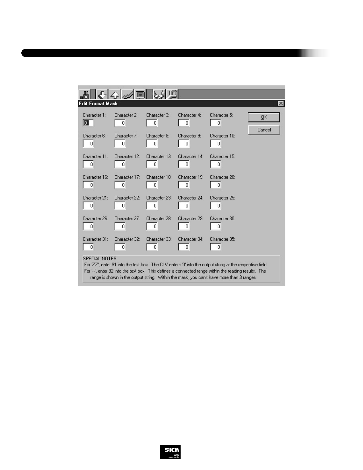
Software Configurations
42
SICK Optic-Electronic
Bar Code Scanners
3
FORMAT MASK
This function conditions the CLV to transmit only specified characters of a read bar code, providing a way to mask the bar code
data transmission to the host device and rearrange the sequence of the data set if required. The user can select up to 35 character positions of a bar code to be transmitted to the host device. Each position can contain up to 2 digits with a numeric value of 0
to 90. Special characters include “--”, “ZZ”, and “OO”. The “--” character is the continuation character, meaning from x to x. The
“ZZ” character places a “0” in the output string and the “OO” character in the first position disables the format mask function or
terminates the condition at the character position entered.
For example, if only the last five positions of a 10-digit bar code are to be transmitted in the sequence they appear in the bar
code label, the first five positions of the Format Mask section would contain 6, 7, 8, 9, 10. The CLV would then only transmit the
sixth, seventh, eighth, ninth and tenth positions/characters of the bar code label.
Note: In the “Reading Diagnostics” mode on the terminal interface line, the bar code data is displayed in its original form. In the
“Monitor Host” mode, the data output is displayed as defined by the Format Mask function.
Figure 3-23 Format Mask
Page 45

Wrong Read Format
There are several different ways the CLV can indicate if the scanner gets a wrong read (no read or no match situation):
- Separator(1) only
- Error String(2) only
- Separator(1) and Error String(2)
- No Error String or Separator
(1) The separator may be defined in “Host Interface; Output Format”.
(2) The error string may be defined under “error string” and will set “count of characters” to 00.
Status 5 Output
Used when the scanner is able to read something, but cannot fulfill the minimum number of multiple reads the user has programmed. The user may select between “error string,” in which case the CLV will output an error string, or “code string,” in which
case the CLV will output the code it was able to read.
Check Max. No. Codes
If “Check Maximum Number Codes” is activated, the CLV will respond with a no read situation if the number of bar codes read
exceed the “Max. No. Codes” value entered in the Code Configuration section. If the error status (ST) statistic is activated, an “A”
will be transmitted to indicate this condition.
Note: The CLV must be programmed to transmit at “End of Clock Pulse”.
HOST PROTOCOL
Defines handshaking schemes, when data is transmitted and in what order from the CLVto the host device. Also the network
mode can be activated. Refer to Appendix C, Table 4 for defaults
43
SICK Optic-Electronic
Bar Code Scanners
3
Software Configurations
Figure 3-24 Host Protocol
Page 46

Software Configurations
44
SICK Optic-Electronic
Bar Code Scanners
3
Protocol Type (Standard/Network)
Protocol is the method of data exchange between the CLV and the host computer. These settings frame the header, separator,
data, and terminator with the selected character values.
Standard (SICK)
“Standard (SICK)” refers to the standard SICK protocol for direct connection of the CLV to a host computer via the host port of
the CLV. (Refer to Figures 4-2 and 4-3)
“Protocol Send Start Character” directs the CLV to insert a selected character at the start of the data string as a start
character for protocol framing. The start character consists of one character and occupies one place in the data string. The character may be 01 to 1F hex. In most cases <STX> = 02 (hex) is used as the start character. This always precedes the header,
separator and terminator.
“Protocol Send Stop Character” directs the CLV to insert a selected character at the end of the data string as a stop character for protocol framing. The stop character consists of one character and occupies one place in the data string. The character
may be 01 to 1F hex. In most cases <STX> = 03 (hex) is used as a stop character. This always follows the header, separator and
terminator.
Note: In order for the CLV utility software to communicate, these values need to be STX and ETX respectively. If not, the software will automatically set the CLV to these values to establish communication. Make sure you reset your requires values during
the last download.
Note: In order for a host device to send the host command language sets to the CLV, the command must be preceded by the
selected receive start character (STX) and must be followed by the selected receive stop character (ETX).
“Protocol Timeout” directs the CLV to repeat the data string last transmitted within the timeout duration, at request of the
host computer. The host must transmit control character <NAK>. Possible settings for timeout have a value from 0 to 9.99 s.
“Protocol X on/X off” directs the CLV to perform data exchange using X ON / X OFF software handshake method. With a
“no” response, the handshake method is not activated.
Protocol Block Check directs the CLV to insert the result of a block check in front of the stop character. Protocol Block
Check [BCC] consists of an element with two characters, representing a type of cross-sum across all the preceding characters of
the data string, including the character of the [START] Section.
[BCC] is determined by XOR linkage of these characters and is transmitted in HEX ASCII form. If [BCC] is inserted in the transmitted data string, the CLV expects the incoming data string to also be equipped with a block check.
Handshake (Nak/Nak Framed/Ack-Nak/Ack-Nak Framed)
“Protocol Handshake” allows the user to select which type of handshake method is to be used. Choose between “Nak,” “Nak
framed,” “Ack-Nak” or “Ack-Nak framed”.
Page 47

Network (CLX 200 Standard/CLX 200 Ack-Nak)
“CLX 200 Standard” enables the CLV to communicate with the CLX 200 without positive confirmation or repetition request. This
must be selected for data exchange with the CLX 200.
“CLX 200 Ack-Nak” enables the CLV to communicate with the CLX 200 in accordance with Ack-Nak protocol.
Please refer to the DNC 200 user manual for more information on our network.
3964 ...... 3964 R-Mode (BCC) (yes/no)/Priority High (yes/no)/RK 512 (yes/no)
This is a customized host interface that will not be used by many users. Contact SICK Optic technical support for detailed information.
Note: If the CLV is in the network mode, the CLV utility software cannot comunicate. Use the icon to establish communication and remember to reset this parameter during the last download.
45
SICK Optic-Electronic
Bar Code Scanners
3
Software Configurations
Figure 3-27 Network Configuration
Page 48

Software Configurations
46
SICK Optic-Electronic
Bar Code Scanners
3
Sending Points
This function allows the user to determine when the scanner should send bar code data and separators to the host. Refer to
Figure 3-28.
(immediately/end of reading/pulse/end of label)
If “immediately” is selected, the CLV will send the bar code data to the host immediately after a successful read. If “end of reading
pulse” is selected, the CLV will send the bar code data after the clock pulse reading gate has ended. If “end of label” is selected,
the CLV will send the bar code data to the host and end the reading gate after the read bar code has moved outside the reading
range of the CLV for at least the programmed time value.
Separator Position (After/Before Code)
If “After” is selected, the CLV will send the separator string after the code is sent. If “Before” is selected, the separator will be sent
before the code data. Refer to Figure 4-2 for examples of each separator position.
Figure 3-28 Sending Points of Bar Code Data
Time of output specified
by parameterization:
Output immediately
after read.
Output at end
of reading gate
(clock pulse)
Reading gate
Successful reading gate
Unsuccessful reading gate
Successful reading gate
Unsuccessful reading gate
Page 49

47
SICK Optic-Electronic
Bar Code Scanners
3
Software Configurations
Output Code Sorting
With this function, the user can determine whether the scanner will send the bar code data from one reading gate according to
the spatial position of the bar code labels (“code position”), the chronological appearance of the codes (“time backward” or
“time”), or code length.
Code Length
“Code Length” refers to the ability to scan several bar codes of different lengths and yet provide a constant data string to the
host. The CLV transmits the data string of multiple labels to the host device sorted by code length. The order in which they are
sent is determined by the code length values entered into the code length list. If the scanner scans more codes than entered in
the list, only the codes of the code length list are transmitted. The value for “Max. No. Codes” is no longer relevant. Identical code
lengths may be entered into the code length list and sorting is based on time decoded. If there is no matching code for a code
length value in this list, the appropriate position is replaced with the error string if the error string is activated. If the programmed
error string is longer than code length the defect string is truncated. If the programmed error string is shorter than the code
length, the last character of the error string is repeated (see example):
2431
1234
1
2
3
4
Scanning
direction
Conveyor direction
Output in data string:
Sorted according to chronological appearance
Sorted according to spatial appearance
Figure 3-25 Code Length
Figure 3-26 Output Code Sorting
EXAMPLE
Error String:
Code Length List:
Scanned Bar Codes:
Output String:
Scanned Bar Codes:
Output String:
Error
09 02 05
22, 55555, 999999999
999999999, 22, 55555
55555, 4444
ERRORRRRR, ER
555555
Page 50

Software Configurations
48
SICK Optic-Electronic
Bar Code Scanners
3
Description
TT = Reading gate duration
In Percent Evaluation Mode this time is directly related to the set scan frequency and scan
expenditure (CA) which is always 100.
MG = Average reading evaluation
n = Number of bar codes detected
DEVE592DAAAJ = Bar code data
C39 = Code 39 (symbology)
ST = Error status
CP = Code position
CL = Code length
CA = Scan expenditure (in this mode of operation always 100 scans)
CS = Code reliability
CK = Code continuity
PERCENT EVALUATION
Percent Evaluation is a continuous scanning mode that generates statistical information used mainly for alignment and adjustment (optimal beam position) when installing the CLV. This operating mode is activated only via the terminal emulation screen of
CLV Utility Software. Table 3-5 shows three examples of statistics generated in this mode.
Figure 3-29 Percent Evaluation
In Percentage Evaluation with 100 scans per reading interval, the “Result LED” indicates the trend in the read quality as follows:
LED off
LED blinks (frequency 2 Hz)
LED blinks (frequency 5 Hz)
LED lights up constantly
good read rate <30%
good read rate 30%...70%
good read rate 70%...90%
good read rate >90%
Device Ready
Result
Laser On
Data
Page 51

49
SICK Optic-Electronic
Bar Code Scanners
3
Software Configurations
CLV Identification
“CLV Identification” is the information that identifies the scanner. It consists of the following information:
Model Number
Identifies the particular type of bar code scanner:
Software Version
A record of the integrated software version.
Part Number
Provides SICK Optic-Electronic model numbers and part numbers for ordering and servicing purposes.
Serial Number
Provides serial number of the scanner.
Testing Date
Provides date of final assembly inspection by SICK Optic-Electronic engineers.
Tester
Provides name of SICK Optic-Electronic inspector who performed the last inspection of the scanner.
User Text
The note book provides space for the user or for SICK Optic-Electronic service engineers to record special information regarding
the scanner or its use. Limited to 30 characters.
Figure 3-30 Operating Data
OPERATING DATA
This section explains the internal operating data recorded by the CLV and how the counter functions can be reset by the user.
Except for the average reading evaluation statistic, operating data are not part of the real-time data set. The user may view this
set of information using the Windows-based CLV Utility Software, if a host device is used, the host, using host command language strings, can query the scanner for this information. Viewing operating data takes the scanner out of the Reading Mode.
Page 52

Software Configurations
50
SICK Optic-Electronic
Bar Code Scanners
3
Counter Contents
The counter collects and records scanner operating statistics regarding accumulated time in operation, number of power-ups, etc.
Operating Hours
By selecting this function, the user can see a running total of the hours the scanner has been in operation.
Power-Up Count
By selecting this function, the user can see a running total of the number of times the scanner has been powered up.
Daily Operating Hours
By selecting this function, the user can see a daily running total of operating hours. This count can be reset by the user via the
counter reset function.
Reading Gates
By selecting this function, the user can see how many times a reading gate has been triggered. This count can be reset by the
user via the counter reset function.
Good Read
By selecting this function, the user can see how many good reads the scanner has obtained. This count can be reset by the user
via the counter reset function.
Average Reading Eval.
The average reading evaluation is a calculated mean value (CGM) of all the values of the identification quality (CG) of reads
determined while the reading gate was active. Anew “smoothed” value MG is formed from this value CGM and the previous
smoothed value MGold.
This statistic is a real-time statistic (MG) determined during the Reading Mode. It also appears as diagnostic reading data in the
header of the output data string. It is calculated by the CLV decoder as explained below:
(a x MGold) - (b x CGM)
MGnew = ———————————-
(a - b)
a=63 b = 1
(63 x MGold) - (1 x CGM)
MGnew = ————————————-
(64)
All values are given as percentages.
This process is referred to as “exponential smoothing.” When there is a jump in the identification quality CG, the half-value of MG
is reached after 44 reads.
Example:
MGold has reached the value 100%. For some unknown reason, new reading gates then always reach the mean value CGM =
50%. In this case, the smoothed value MGnew has dropped to 75% after 44 reads, reaches 67% after a further 44
The value of MG provides an overall indication of the state of the CLV during the previous period and can therefore be used as a
quality characteristic for the reading configuration as a whole. Among other things, the reading quality depends on the quality of
the printed bar code, the positioning and parameterization of the CLV, contamination of the reading window and any “bouncing” of
the reading gate due to an incorrectly set external clock-pulse generator.
Page 53

51
SICK Optic-Electronic
Bar Code Scanners
4
Operation
SECTION IV - OPERATION
This section describes functions important to the operation of the CLV scanner following installation and programming. Explained
here: initial power up and testing, checking the reading mode, fine optical alignment, function of indicator lights, explanations of
messages sent by the CLV, interpretation of output data strings, and description of read quality. At the end of this section is a brief
discussion of CLV operation using host command language strings (which will apply to only a few users since most will be working with the integrated menu-driven software or the Windows-based CLV Utility Software).
POWER-UP
Apply supply voltage to the CLV. This initiates the self test. After the self test has been successfully completed, the message
“Read Parameters...” will appear. This indicates that the CLV is loading current parameter settings from its memory. The CLV then
switches automatically to “Reading Mode” and the green “Device Ready” LED lights, indicating that the scanner is ready for operation in the reading mode.
If the scanner is already powered up and in the Parameterization Mode, access the Reading Mode by selecting “Quit Menu” from
the functionality menu.
CHECKING THE READING MODE
If a red laser diode is used as the light source, insert a piece of paper into the path of the beam. The red beam should be visible
when the CLV is triggered.
To check the operation of the Reading Mode, perform the following steps:
With conveyor facility stopped:
1. Activate reading gate by triggering the trigger source. If an external clock pulse is being used, trigger the device (photoelectric
switch, for example,) by covering the reflector. With free-running clocking, the CLV will trigger the reading gate when a bar
code label is detected. With external software triggering, a command string from the host device will trigger the reading gate.
2. Present a bar code label to the CLV. If all parameters are correctly set, output data will be transmitted to the host and/or is dis
played using a terminal emulation device on the terminal port.
3. Check that the host device has received the data.
4. If an error message should appear on the display, proceed as in Section V-Maintenance and Troubleshooting.
With conveyor facility in operation:
After conveyor facility is powered up, test bar code reading under operating conditions.
1. Pass conveyed products with bar code labels past CLV.
2. If conveyed products are not guided as desired, simulate various settings and observe effect on reading success.
3. Check that the host device has received the data.
4. If an error message should appear on the display, proceed as in Section V “Maintenance and Troubleshooting.”
Page 54

Operation
52
SICK Optic-Electronic
Bar Code Scanners
4
Optical Alignment
Once the trial run has been successfully completed, fine optical alignment of the CLV on the conveyor line can be carried out.
Activation of the “Percent Evaluation” mode is recommended to enable the CLV to continuously evaluate the number of valid and
invalid reads and indicate the result as a percentage. With this information, the CLV can be optically aligned to obtain the most
efficient reading process.
To improve the reading efficiency of the CLV, check the following:
Is the minimum bar thickness correctly selected?
Is the reading range on its optimum setting? If the reading distance fluctuates, does it
stay within valid limits?
Is the reading angle of the scanner acceptable?
Is the scanning frequency set for optimum performance?
Is the start/stop ratio correct?
Is the trigger source triggering properly?
For data transmission: are the host interface parameters correctly set?
Was the correct function selected for the auxiliary interface?
Indicator LEDs
Figure 4-1 shows the indicator light panel of the CLV. There are four indicator lights: “Device Ready,” “Result,” “Laser On” and
“Data.” These are explained below:
The “Device Ready” LED indicates that the scanner is in the reading mode. When the
scanner is powered up, the reading mode is automatically activated.
Note: If the “Device Ready” LED does not light upon power-up, this is an indication that
the scanner has failed its system self test.
The “Result” LED can be programmed to go on or off based on the following conditions:
Good Read, No Read, Match 1, Match 2, Mismatch 1, Mismatch 2, No Match, etc. See
Section III-”Parameterization: Device Configuration: Result Output.” Default setting is
Good Read.
The “Laser On” LED is activated when a reading gate is triggered and the laser diode is
activated.
The “Data” LED is lit when the CLV transmits data to the host device via the host interface.
Device Ready
Result
Laser On
Data
Figure 4-1 Indicator LEDs
Page 55

53
SICK Optic-Electronic
Bar Code Scanners
4
Operation
Messages in the Reading Mode
During operation, the CLV outputs various messages on the display of the host device or on the screen of an ASCII terminal.
Messages can be canceled by pressing any key on the keyboard. Table 4-1 explains the messages that may appear in the
Reading Mode.
Read Quality
Bar code data will be sent to the host computer according to evaluation criteria programmed by the user. The paragraphs below
explain the difference between what the CLV considers a “good read” and a “wrong read” (called a “no read” here).
Good Read
If all specified evaluation criteria (e.g. number of multiple reads, match code comparison, etc.) have been satisfied, a reading gate
is referred to as a “good read” and will be output in the format selected by the user.
No Read
If all of the selected evaluation criteria (e.g. multiple reads, match code, etc.) have not been satisfied, or if the scanner can not
detect any bar codes, a reading gate is considered unsuccessful (“wrong read”). In the event of a “no read,” the CLV can output a
user-definable error string message that can consist of either the (user-definable) separator only, the (user-definable) error string
only, both the separator and the error string, or nothing at all. If the scanner is able to read something but can not fulfill the minimum number of multiple reads specified by the user, the CLV can output the message “ST=5” with either an error string or the
code the scanner was able to read. To program the output format of a no read situation, see Section III, “Output Format: Wrong
Read.”
Page 56

Operation
54
SICK Optic-Electronic
Bar Code Scanners
4
OUTPUT INTERPRETATION
The output of a read consists of the decoded content of up to three different bar codes, plus diagnostic reading data. Diagnostic
reading data is described separately in detail. The bar code data is carried in a structured string as shown in Figure 4-2. The
string consists of elements combined to form the following blocks:
Start character
Header (diagnostic reading data and selectable constants)
Bar code data
Separators (diagnostic reading data and selectable constants)
Terminator (diagnostic reading data and selectable constants)
Stop character
The user may specify form and content of the data string to be sent to the host (refer to Section III, “Output Format”). The auxiliary interface, operating in the “Monitor Host” mode, displays the data string configured for use with the host interface. Two examples of decoded bar code data are given in Figure 4-2.
In Example 1, the protocol start and stop
characters are used to frame the information with start of text and end of text
ASCII control characters. The terminator
provides the carriage return and line feed
control characters.
In Example 2, the protocol framing characters are not used. The data transmitted
along with two sets of statistics delimited
by a comma. The statistics and commas
are selected within the separator field. At
the end of the string, a carriage return
and line feed are included as part of the
terminator field.
Figure 4-2 Diagnostic Reading Data Statistics
Table 4-1 Diagnostic Reading Data Statistics
Page 57

55
SICK Optic-Electronic
Bar Code Scanners
4
Operation
DIAGNOSTIC READING DATA
The CLV bar code scanner is able to continuously generate diagnostic reading data and integrate this into the data output string for evaluation by the user. Diagnostic
reading data is transmitted in the header, separators and/or terminator of a data string. The user is able to define the content of each of these elements of the data
string in the Parameterization Mode (see Section III, “Parameterization: Host Interface: Output Format”). Table 4-1 defines the statistics available to the user and provides information on the output location of each statistic. Figure 4-3 shows how the statistics are calculated.
Description Abbre- Function Determination Transmission Figure
viation in block
Error Status ST • Indicates cause of unsuccessful read diagnosed For every Separator –
by CLV. Eight different error status codes bar code label
are available: in a single
ST=A: Programmed maximum number of codes reading gate
has been exceeded
ST=0: Good read
ST=1: Wrong check digit
ST=2: No read
ST=3: System error
ST=5: Number of multiple reads specified have
not been fulfilled
ST=6: Master unit does not identify the proper
number of slave units
ST=7: Source of bar code data is auxiliary input
via auxiliary interface
ST=8: Data loss in networking operation
ST=9: Match code filter stopped transmission
• The error status is a criterion for the insertion of
code error strings (space savers) in the host
interface data string.
Code I D • Provides code letter for assignment of bar code –
Identification contents to type of code symbology from which
it comes, e.g, “a”=Codabar
Code Length CL • Indicates number of digits of decoded bar code –
contents Serves to indicate appropriate data field
in data string; permits further data processing,
even with free code lengths
Code Position CP • Indicates position on scanning line at which bar 3-2
code label is detected (position of first dark bar)
Numerical values from 000 to 100 are used to
designate relative position Resolution is 10°.
• Line scanner example: several bar code labels
arranged consecutively in a row receive different
position designations. Codes with identical
contents can therefore be detected as nonredundant and be output
Code CS • Indicates total number of all scans in which iden- 4-4
Reliability tical bar code contents were detected. Indication
of trend of reading reliability at reading station
• Practical application: direct on-line monitoring of
individual reading stations
Code CK • Indicates maximum number of consecutive 4-4
code quality
Page 58

Operation
56
SICK Optic-Electronic
Bar Code Scanners
4
Description Abbre- Function Determination Transmission Figure
viation in block
Scan CA • Indicates total number of scans required For every bar _ 4-4
Expenditure to fulfill specified number of multiple reads code in a single
(identical scans) reading gate
Total Scan GCA • Internal arithmetical number representing the _ 4-4
Expenditure number of all scans taking place in period
between first and last identical scans The
number depends both on the bar code quality
and on the specified transmission time
(sending point) of bar code data
Identification CG • Indicates relative measure of quality for Separator 4-4
Quality reading status for one reading gate. The
decoder calculates this value as follows:
CS
CG = –––––– x 100%
GCA
Reading Gate TT • Indicates length of time from the beginning of For every Terminator –
Duration the reading gate until evaluation criteria are met reading gate
for all bar gate code labels encountered.
Number of CC • Indicates number of all bar code labels detected Header / _
Codes according to selection criteria Terminator
Detected
Device ID GN • Indicates the CLV identification number in a Terminator _
Number CLX 200 network configuration
Average MG • Indicates average value of identification quality Header _
Reading (CG) from preceding reading gates
Evaluation
The decoder calculates this value as follows:
(a x MG
old
) - (b x CGM)
MG
new
= —————————————
(a-b)
a = 63
b = 1
(63 x MG
old
) - (1 x CGM)
MG
new
= —————————————— %
64
• The average value provides a trend indication
for the reading performance of the CLV from
preceding period up to the present
Page 59

57
SICK Optic-Electronic
Bar Code Scanners
4
Operation
Key:
CA = Scan Expenditure
GCA = Total Scan Expenditure
CS = Code Reliability
CK = Code Continuity
CG = Identification Quality
1 2 3 4 5 6 7 8 9 10 11 12 13 14 15 16 17 18 19 20 21 22 23 24 25 26 27
Reading Gate
N Scans in
Reading Gate
Time-Related
Distribution and
Number of Identical
Scans
CS = 12
CK = 5
Multiple Reads: 3
(parameter setting)
CA = 4
GCA = 24
123 45678 91011 12
12345
123
1234
1 2 3 4 5 6 7 8 9 10 11 12 13 14 15 16 17 18 19 20 21 22 23 24
Figure 4-3 Determination of Diagnostic Reading Data (all data for one bar code label)
If the CLV is set to send bar code data immediately, it will
stop scanning after the programmed number of multiple
reads has been fulfilled.
CS 12
CG = ––––– x 100% = ––––– x 100% = 50%
GCA 24
Page 60

Action Data String Meaning
Host Transmission <STX> 21 <ETX> Command to activate reading
gate of scanner.
Echo of CLV <STX> 21 <ETX> Command to activate reading
gate of scanner has been
accepted.
Response from CLV <STX> 3 ERR <ETX> –
in case of Invalid
Values
Operation
58
SICK Optic-Electronic
Bar Code Scanners
4
Operation Using Host Command Language Strings
Table 4-3 shows an example of the use of command strings from the host interface to the CLV. If using a host device with command strings, refer to the CLV Command Language Guide (a SICK Optic-Electronic publication) for information regarding other
command strings.
Similar to the menu-assisted approach, all parameters (except data format of the host interface) can be customized as described.
With a host device, for example, the user can program each reading station of a conveyor installation individually, and reinitialize
them following start-up.
Figure 4-3 Command String Function
Page 61

59
SICK Optic-Electronic
Bar Code Scanners
5
Troubleshooting
SECTION V -MAINTENANCE AND TROUBLESHOOTING
The CLV Bar Code Scanner is essentially maintenance-free. This section will cover preventive maintenance measures such as
cleaning of the optical surfaces and the system self test. Error messages that can occur in the Parameterization, Reading, and
Percent Evaluation modes are also discussed here.
CLEANING OPTICAL SURFACES
Depending on the operating environment of the CLV (amount of dust, humidity, etc.), these optical surfaces should be cleaned on
a regular basis:
• CLV reading window
• Exit window of photoelectric switch, if applicable, and the surface of the reflector (follow sensor instructions)
CAUTION: No aggressive scouring agents or solvents should be used. These can damage glass surface of reading window or
plastic surfaces.
CLV Reading Window
If the read quality of a consistently good bar code print is low, this could indicate that the CLV window is dirty. A soft, lint-free
cloth dampened with a mild water-soluble cleaning agent is recommended for cleaning. Do not use a scouring motion when
cleaning.
Exit Window of Photoelectric Switch
If an external hardware trigger such as a photoelectric switch is being used as a clocking method, the exit window of the sensor
should be cleaned according to the manufacturer’s instructions.
Page 62

CLV SYSTEM SELF TEST
The system self test is a functional test of the CLV system electronics, the memory, and the visible laser diode. If the scanner
fails its self test, the reading mode will not be activated and the “Device Ready” LED will not light.
ERROR MESSAGES
If errors occur in a selected operating mode, the CLV signals the diagnosed error via the auxiliary interface for indication at the
display of the host device. Some error messages are also output in the host interface data string. Tables 5-1 through 5-3 list the
error messages that may appear in the Parameterization, Reading, and Percent Evaluation modes and include information on the
possible time of occurrence, meaning, possible cause, and steps that should be taken by the user to correct the condition.
SICK OPTIC-ELECTRONIC SERVICE
If the measures recommended in this manual fail to restore the CLV to proper operation, contact the SICK Optic-Electronic
technical support staff at (612) 941-6780
.
Troubleshooting
60
SICK Optic-Electronic
Bar Code Scanners
5
Page 63

61
SICK Optic-Electronic
Bar Code Scanners
5
Troubleshooting
1. The CLV is not ready:
- The Dev.Rdy LED is not lit
- The Result 1 switching output (default: Dev. Rdy) is disabled.
2a. Reading Mode: (Dev.
Rdy LED lit) Trigger Pulse:
reflector polling
The CLV cannot be clocked.
- The Laser On LED flickers
but does not remain lit.
- Red-light scanner: the scan
line is very faint
1. The operating voltage
(4.5...30 V DC) is not connected.
2. The CLV is not in Reading
Mode.
3. The CLV has detected a
malfunction during the self-test.
1. Incorrect reading pulse
source set in parameters.
2. Reading distance incorrect.
3. Polling reflector incorrect
4. Incorrect pulse sequence
(reflector is not covered to start
the reading interval).
1a. Check power supply.
1b. Mechanical noise?
2. Determine mode of Reading Mode.
Operation E.
3a. Switch the device off and on again.
Does the LED now light up after approx.
10 s?
3b. Has the CLV sent the status ST=3 in
the data output string (prerequisite: ST is
enabled for output in the separator)?
1. Are the device parameter settings for
the reading pulse correct?
2. Is the reading distance within the
defined reading field?
3. Is the polling reflector suitable for the
reading distance?
4. Is the reflector polling sequence cor-
rect? (read: 1. cover reflector, 2. read bar
code, 3. uncover reflector)
1a. Check the wiring. Measure
the voltage value.
1b. Listen to the housing for
scanner motion & noise.
2a. Return to Reading Mode.
2b. Switch the device off and on
again.
3a. If so, the device is OK. If not,
contact the SICK Service
Department.
3b. If so, contact the SICK Service
Department.
1. User interface: choose Reflector
Polling in Edit Reading Pulse
Mode on the Device Configuration
card; download to CLV.
2. Change reading distance.
3. Choose correct reflector.
4. Adjust sequence.
Malfunction Possible Cause Check Remedy
ERROR MESSAGES IN READING MODE
Page 64

Troubleshooting
62
SICK Optic-Electronic
Bar Code Scanners
5
ERROR MESSAGES IN READING MODE
2b. Reading mode:
(Dev. Rdy LED lit)
Trigger Pulse: external
sensor
The CLV cannot be
clocked via the Sensor
2 switching input.
- The Laser On LED does
not light up.
- Red-light scanner: the scan
line does not appear.
2c. Reading Mode:
(dev. Rdy LED lit)
Trigger Pulse: ser. interface
The CLV cannot be
clocked.
- The Laser On LED does
not light up.
- Red-light scanner: the scan
line does not appear.
3. Reading Mode:
(Dev. Rdy LED lit)
The Result LED does
not light up at the end
of the reading pulse.
- The CLV outputs the status
ST=2 in Reading mode (if ST
is enabled for the separator).
- The Result 2 switching output (default: good read) does
not supply a pulse.
1. Incorrect clock pulse source
defined in parameters.
2. The photoelectric switch is
not aligned with the reflector
(photoelectric proximity switch
or inductive transducer not
dumped).
3. The external sensor is not
connected correctly.
4. No ground potential (if sensor supplied by CLV).
1. Incorrect clock pulse source
is defined in the parameters.
2. The CLV is not receiving any
command strings for the pulse
via the data interface.
1. Read not successful since
no bar code was in the reading
field during the reading pulse.
2. Match code comparison: the
read bar code does not match
the specified match code.
3. Scan line positioned incorrectly.
1. Are the device parameter settings for
the reading pulse correct?
2. Check the function of the external sensor and whether it is obstructed.
3. Check sensor wiring.
4. Is the jumper inserted between pin 5
and pin 15?
1. Are he device settings for the reading
pulse correct?
2a. Check the CLV host interface parameters.
2b. Check the data connection between
the CLV and host.
2c. Check the host command string.
1. Check timing between pulse and presence of bar code in the reading field.
2. Not applicable.
3. Is the bar code at the center of the scan
line (optimal)?
Malfunction Possible Cause Check Remedy
1. User interface: choose Sensor
Input in Edit Reading Pulse Mode
on the Device Configuration card;
download to the CLV.
2. Align the sensor correctly.
3. Measure the output signal of the
sensor and the input signal on the
CLV.
4. If not, insert jumper.
1. User interface: choose Serial
Interface in Edit Reading Pulse
Mode on the Device Configuration
card; download to the CLV.
2a. User interface (after upload
from CLV): check Data Format,
Protocol, Start and Stop Character
on the Host Interface card.
2b. Pin assignment and connection diagram.
2c. User interface (after upload
from CLV): check Serial Interface
in Edit Reading Pulse on the
Device Configuration card. Check
host interface in Terminal.
1. See malfunctions 2a, 2b or 2c.
Synchronize clock pulse accordingly.
2. None.
3. Align the CLV. User interface:
call Percentage Evaluation mode
and test the readability of the bar
code.
Page 65

63
SICK Optic-Electronic
Bar Code Scanners
5
Troubleshooting
3. Reading Mode:
(Dev. Rdy LED lit)
The Result LED does
not light up at the end
of the reading pulse.
(cont)
4. Bar code presented at incorrect reading distance.
5. Reading configuration of the
CLV parameterized incorrectly
for the presented bar code.
6. Reading angle at which the
bar code appears is too large
(e.g. bar code slanted on
object)
7. CLV is in total reflection.
8. Evaluation criteria for bar
code types set incorrectly
(Code Configuration).
9. Code position reading zone
(CP values) have been
changed (default: Min. CP=0,
Max. CP=100).
10. The defined minimum number of bar codes to be read is
higher than the actual number
in the reading pulse.
11. Bar code quality is not sufficient.
4. Is the reading distance feasible with this
device type in relation to the module width
of the bar code?
5. Are the values for min. reading distance
and min. bar code thickness correct?
6. Tilt, skew or pitch of bar code on scan
line incompatible?
7. The scan line should strike the bar code
at a skew of approx. 15 degrees.
8a. Are code type and length parameterized correctly? Determine code type to be
read: enable all code types, set code
lengths to Free, download to CLV temporarily. Call Percentage Evaluation, present bar code, the code type is displayed
followed by the read quality.
8b. Determine Code length to be read:
enable code type, set code length to Free,
download to CLV temporarily. Call
Percentage Evaluation, present bar code,
the code length is displayed.
9a. Check setting on Reading
Configuration card.
9b. Does active evaluation zone coincide
with position of bar code in the scan line?
10. User interface (after upload from CLV):
Check Number of Codes menu option on
Code Configuration card.
11a. Number of idle zones sufficient (min.
10x module width, min. 2.5 mm)?
Segmentation setting on Reading
Configuration card set to Start/Stop?
11b. Is print contrast sufficient?
11c. Print tolerances (according to specification) exceeded?
Malfunction Possible Cause Check Remedy
4. Adjust distance.
5. User interface: enable all code
types on the Code Configuration
card. Download to CLV temporarily. Call Percentage Evaluation
mode, choose sample code with
matching module width and check
the reading range from min. to
max. reading distance (read quality .70%). Adjust read configuration
if necessary.
6. Readjust CLV if necessary to
optimize reading angle.
7. Optimize CLV alignment.
8a. User interface: activate detected code type under Edit Codes on
the Code Configuration card, disable all other types, download to
CLV.
8b. User interface: set the code
length for the relevant code type in
Edit Codes on the Code
Configuration card; download to
CLV.
9. User interface: call Percentage
Evaluation and test readability of
bar code at the center of the scan
line.
10. Adjust value accordingly (for
one code: min./max. = 1); download to CLV.
11a. Check read with fault-free reference code. Bar code: enlarge
label, reduce module width or print
ratio (min. 2:1).
11b. Submit device for test (e.g. by
SICK Service Department)
11c. See 11b.
ERROR MESSAGES IN READING MODE
Page 66

Troubleshooting
64
SICK Optic-Electronic
Bar Code Scanners
5
ERROR MESSAGES IN READING MODE
4. Reading Mode: (Dev.
Rdy LED lit)
CLV does not transfer
reading result to host.
- The Data LED does not
flicker at the end of reading
pulse.
5. Reading Mode:
(Dev. Rdy LED lit)
CLV outputs ST=3 in
Reading Mode (If ST is
enabled for the separator)
6. Reading Mode:
(Dev. Rdy LED lit)
Output of bar code content incorrect or incomplete.
1. The CLV is not in Reading
Mode.
2. No reading pulse supplied.
3. Data connection cable wired
incorrectly.
4. Voltage level incorrect.
5. Host interface parameters
incorrect.
CLV has diagnosed a device
malfunction
-The CLV has diagnosed a
device malfunction
1. 2/5 Interleaved: CLV suppresses the first character of
the code in the data output
string.
2. CLV suppresses the last
character of the code in the
data output string.
3. CLV outputs non-definable
characters.
1. Is the Dev. Rdy LED lit?
2. Is the Laser On LED lit at the corresponding clock pulse?
3. Check wiring.
4. Values OK?
5a. Check data format, protocol, start and
stop characters and output format.
5b. With output sorting according to code
length list: check specified lengths (at
lease one -0)
Switch device off and on again, Does
LED light up after approx. 10 s?
-Switch device off and on again.
Does LED light up after approx. 10 s?
1. Does the CLV suppress the leading
zero?
2. Output of the last character is disabled
for this code type.
3. Data format set incorrectly.
Malfunction Possible Cause Check Remedy
1. If not, switch device off and on
again.
If so, user interface: choose
Reading Mode.
2. See malfunction 2a, 2b or 2c.
3. Check pin assignment and connection diagram.
4. Measure voltage values.
5a. User interface (after upload
from CLV): check settings on the
Host Interface and Data Strings
card and change if necessary.
Download to CLV.
5b. User interface (after upload
from CLV): check settings on the
Data Strings card and change
them if necessary. Download to
CLV.
If so, the device is OK. If not or if
the malfunction occurs again: contact the SICK Service Department.
-If so, the device is O.K. If not or if
the malfunction occurs again: contact the SICK Service department
1. User interface (after upload from
CLV): activate the Transmit
Leading Zero field for 2/5
Interleaved under Edit Codes on
the Code Configuration card and
change them if necessary.
Download to the CLV.
2. User interface (after upload from
CLV): check the settings for the
code type under Edit Codes on the
Code Configuration card and
change them if necessary.
Download to the CLV.
3. User interface (after upload from
CLV): check the values under Data
Format on the Host Interface card
and change them if necessary.
Download to the CLV.
Page 67

65
SICK Optic-Electronic
Bar Code Scanners
5
Troubleshooting
ERROR MESSAGES IN READING MODE
7. Reading Mode:
(Dev. Rdy LED lit)
Read OK, however, the CLV
does not output the reading
result until after the end of
the reading pulse in immediate output mode.
8. Reading Mode: The
scan line is not visible during
the reading pulse.
The Dev. Rdy LED extinguishes.
9. Reading Mode:
Dev. Rdy LED lit)
The Result 1...3 switching
outputs do not supply a
pulse.
10. CLV responses are
not acknowledges by
beeper.
11. AutoSetup:
CLV does not read the presented, application-specific
bar code (no acknowledgment from beeper)
1. User interface (after upload
from CLV): check Number of
Codes menu option on the
Code Configuration card.
2. User interface (after upload
from CLV): check settings
under Edit Codes on the Code
Configuration card (enabled
code type, code length)
-Reading interval terminated
incorrectly; the internal monitoring function deactivated the
laser diode after 10 min. for
safety reasons.
1. The result for the assigned
result display function does not
occur in the reading process.
2. Outputs switching incorrectly.
-Beeper deactivated (beeper
volume: OFF)
1. CLV not in AutoSetup mode
2. With profile programming:
CLV wait time of 5 s after
power-up exceeded
4a. CLV replaces each control character in
the protocol frame with @. Because control characters are transferred in code:
Hex ASCII output activated?
4b. Are characters outside the code
referred to in the format mask?
1. Not applicable
2. Are outputs set to Invert Outputs?
Check the beeper parameter settings
1. Is Dev. Rdy LED lit? If so, the CLV is in
Reading Mode again.
-Check the function fo the reading pulse
(particularly at end of reading interval)
1. Not applicable
2. Are ouputs set to INVERT OUTPUT
.
-Check the beeper parameter settings
1. Is Dev. Rdy LED lit? If so, the CLV is
in reading mode again.
Malfunction Possible Cause Check Remedy
4a. User interface (after upload
from CLV): check settings for relevant code types under Edit Codes
on the Code Configuration card
and change them if necessary.
Download to the CLV.
4b. User interface (after upload
from CLV): check settings under
Edit Code Length List on the Data
Strings card.
1. Adjust the value accordingly (for
one code: min./max.=1).
Download to the CLV.
2. Only enable the actual bar code
types that are to be read.
Download to the CLV.
Clock the CLV again.
-Clock the CLV again.
1. None
2. User interface (after upload from
CLV): check settings for Result
1...3 under Edit Result Outputs on
the Device Configuration card.
-User interface (after upload from
CLV): check volume setting under
Result Output on the Device
Configuration card.
1. User interface (after upload from
CLV): call Auto Setup again in the
View menu.
2. Switch CLV off and on again,
present profile bar code number
10 within 5 s.
Page 68

Troubleshooting
66
SICK Optic-Electronic
Bar Code Scanners
5
ERROR MESSAGES IN READING MODE
11. AutoSetup:
CLV does not read the
presented, applicationspecific bar code
(no acknowledgment from
beeper)
12. Profile
programming
3. Profile programming: CLV
wait time of 10 s after presentation of first profile bar code
exceeded.
4. Reading distance for presented bar code incorrect.
5. CLV is in total reflection.
6. Bar code quality insufficient.
1. CLV not in teach-in mode.
2. CLV wait time of 5 s after
power-up exceeded.
3. CLV wait time of 10 s after
presentation of first profile bar
code exceeded.
3. See 1.
4. Is reading distance for this module
width OK?
5. Is bar code presented at a skew of less
than 15 degrees?
6. See point 3.11a, b, c.
1. Is Dev. Rdy LED lit? If so, the CLV is in
Reading Mode again.
2. See 1.
3. See 1.
Malfunction Possible Cause Check Remedy
3. See 2.
4. Adjust reading distance.
5. Rotate bar code accordingly.
6. See point 3.11a, b, c.
1. Switch CLV off and on again,
present required profile bar code
immediately.
2. As 1.
3. As 1.
Page 69

Scanning Characteristics
Scanning Method 8-sided polygon mirror wheel
Aperture Angle 60° (50° with right angle version)
Scanning Frequency 200 to 800 Hz
Light Source visible laser diode (670 nm)
Power Rating Average power at reading window: maximum 1 mW
Laser Class IEC 825 Laser Class 2 (CDRH Laser Class II)
Reading Distance 40 m to 400 m (1.5 in to 16 in)
Resolution CLV 410 - 0.2 mm to 1.0 mm (.008 in to .040 in) CLV 412 - 0.1 mm to .2mm (.004 in to .008 in)
Bar Code Types
Bar Code Symbology Code 39, Interleaved 2/5, Industrial 2/5
Codabar, Code 93, EAN/EAN 128, UPC, Code 128, Pharmacode
Readability 10 bar codes per reading
Autodiscrimination 3 different symbologies per scan or reading gate
Multiple Reads 1 to 99
Communication
Host Interface RS 232 and RS 422/485
Baud Rate 300 to 57,600
Data Format Data bits, stop bits, parity
Data String Format ASCII (header, separator, terminator)
Network Configuration Pass-through; master/slave; RS 485 network
Trigger Methods
I/O Interface Hardware trigger
Host Interface Software trigger
Free-Running Continuous scanning
Reflector Polling Automatic Trigger
Electrical Specifications
Supply Voltage 5-30 V DC (± 5% at 5 V DC, ± 20% at 24 V DC)
Current Consumption 100 mA
LED Indicators Device ready, result, laser on, data
Switching Inputs 2 x PNP, opto-decoupled, maximum 30 V DC. Internal delay 30 ms
Switching Outputs 3 X PNP, maximum 600 mA / 24 V DC: device ready, read result
Enclosure Rating IP 54 (NEMA12), FCC Class APart 15 compliance/class 3 (VDE 0106) (IP 65 optimal)
Ambient Operating Temperature 0 to 40°C (32 to 104°F)
Storage Temperature -20 to 70°C (-4 to 158°F)
Vibration Test To IEC 68-2-6 test FC
Shock Test To IEC 68-2-27 test EA
EMV Test To IEC 801
Max. Rel. Humidity 90% non-condensing
Connecting Cable 15-pin male Sub-D high density, .9 m (3 ft) cable length
Dimensions (L x W x H) 59 mm x 62.7 mm x 35.2 mm (2.32 in x 2.47 in x 1.39 in)
Weight Approximately 250 g (8.75 oz)
67
SICK Optic-Electronic
Bar Code Scanners
6
Specifications
TECHNICAL SPECIFICATIONS
Page 70

Specifications
68
SICK Optic-Electronic
Bar Code Scanners
6
105¡
4 mm
(.15 in)
M4, 6 mm (.23 in) deep
AVOID
EXPOSURE
LASER
RADIATION
EMITTED FROM
THIS APERTURE
35.2 mm
(1.38 in)
32.8 mm
(1.30 in)
59 mm
(2.32 in)
13.2 mm
(.52 in)
14.4 mm
(.57 in)
6¡
15.3 mm
(.60 in)
0.2 mm
(.08 in)
60¡
39.3 mm
(1.56 in)
72 mm
(2.83 in)
35.9 mm
(1.42 in)
45.8 mm
(1.82 in)
50¡
39.3 mm
(1.56 in)
Line/raster scanner with end scanning housing
Right angle line/raster scanner with side scanning housing:
35.2 mm
(1.39 in)
27.1 mm
(1.08 in)
62.7 mm
(2.47 in)
62.7 mm
(2.46 in)
10 mm
(.39 in)
32.8 mm
(1.30 in)
14.4 mm
(.57 in)
10 mm
(.40 in)
4 mm
(.16 in)
M4, 6 mm (.23 in) deep
CLV 410 / 412 / 414
Page 71

69
SICK Optic-Electronic
Bar Code Scanners
7
Accessories
46.5
20 4.36.5
4.5
19
4.1
30˚
30˚
45˚
26.5
6.5
4.5
23.5
11
5.1
5.3
30
18
7
6
19
4.3
4.1
30˚
30˚
30˚
45˚
23.5
11
5.1
5.3
30
18
7
6
30˚
10
11
Figure 7-1 Mounting brackets
Terminal
Host CLV
80 mm
115 mm
Mounting hole ø˘
4 mm ( .157")
161 mm
103 mm
90 mm
59 mm
Figure 7-2 PS 52 Unit Dimensions
MB-CLV410S
MB-CLV410L
Page 72

Appendices
70
SICK Optic-Electronic
Bar Code Scanners
8
CONFIGURATION DEFAULTS
Parameter
Reading Configuration
Scan Frequency (Hz)
Minimum Bar Width
Minimum Dist.
Maximum Dist.
Segmentation
Clock Pulse - Source Clock Pulse
Minimum CP
Maximum CP
Switching Outputs: 1
Result Output 2
Match Code 3
Device ID Number
Master/Slave
Setting
CLV 410 / 412
500 Hz
50 mm (.020)
40 mm (1.6 in)
Start Stop Ratio
Reflector Polling
End Clock Pulse
0
100
Device Ready
90 Read
No Read
1
Stand alone
Parameter
Code Type
Code Length
Multiple Reads
Check Digit Test
Transmit Check Digit
Transmit Start / Stop
Identical Start / Stop
Transmit Leading Zero
Add-On
Full ASCII
Output Hex-ASCII
FCI First Char.
FCI in Code String
Code Type
Code 39
Active
Free
3
No
Yes
No
-
-
No
No
-
-
Int. 2/5
Active
Free
3
No
Yes
-
Yes
-
-
-
-
-
EAN
8-digit active
13-digit active
3
Yes
-
-
None
-
-
-
-
UPC
Version AON
Version E ON
3
3
Yes
-
-
None
-
-
-
-
Codabar
Active
Free
3
No
Yes
No
No
-
-
-
-
-
-
Code 128
Active
Free
3
-
-
-
-
-
-
No
-
-
Code 93
Active
Free
3
No
-
-
EAN 128
Active
Free
3
No
5D4331 hex
ID0000 hex
Code Configuration
Decoder
Min. No. of Codes
Max. No. of Codes
CP - Comp. Multir.
Min. Dist. Labels
T - Code Labels
Multiple codes on object
Standard
1
1
yes
50 mm
No
No
Default Configurations for Each Bar Code Type:
Default Configurations for Each Bar Code Type:
Page 73

71
SICK Optic-Electronic
Bar Code Scanners
8
Appendices
CONFIGURATION DEFAULTS
Baud rate
Parity / Data bits
Stop bits
Header
Separator
Terminator
Wrong read
Output code sorting
Standard (SICK)
Network
Test string active
Test string timer
Test string contents
S/T reading result
S/T separator
Parameter
Data Format
Output Format
Protocol
Test String
Sending Points
No read format
Def error string
Contents
Output with ST=5
Check max. # if codes #
Pro send start shar
Pro send stop char
Pro receive start char
Pro receive stop
Pro timeout
Pro Xon / Xoff
Pro block check
Pro handshake
DNC 200 standard
Setting
9600
8 / none
1
Blank
Blank
Blank
Error String & Separator
1
No Read
Err String
Code Position
02 <STX>
03 <ETX>
02 <STX>
02 <ETX>
50 ms
No
No
Nak
No
300 ms
54 hex = <T>
End of Pulse
Code
Page 74

CHARACTER
(NULL)
(SOH)
(STX)
(ETX)
(EOT)
(ENQ)
a
(ACK)
(BEL)
----
(BS)
(HT)
(LF)
(VT)
(FF)
(CR)
(CR)
(SI)
(DLE)
(DCI)
(DC2)
!! (DC3)
(DC4)
§ (NAC)
(SYN)
(ETB)
(CAN)
(EM)
(SUB)
(ESC)
(FS)
(GS)
RS)
(US)
Appendices
72
SICK Optic-Electronic
Bar Code Scanners
8
❤
♦
♣
♠
ASCII CHARACTER SET
DEC
000
001
002
003
004
005
006
007
008
009
010
011
012
013
014
015
016
017
018
019
020
021
022
023
024
025
026
027
028
029
030
031
HEX
00
01
02
03
04
05
06
07
08
09
0A
0B
0C
0D
0E
0F
10
11
12
13
14
15
16
17
18
19
1A
1B
1C
1D
1E
1F
CONTROL
CODE
CTRL @
CTRL A
CTRL B
CTRL C
CTRL D
CTRL E
CTRL F
CTRL G
CTRL H
CTRL I
CTRL J
CTRL K
CTRL L
CTRL M
CTRL N
CTRL O
CTRL P
CTRL Q
CTRL R
CTRL S
CTRL T
CTRL U
CTRL V
CTRL W
CTRL X
CTRL Y
CTRL Z
CTRL [
CTRL \
CTRL ^
CTRL ???
CTRL ???
DEC
032
033
034
035
036
037
038
039
040
041
042
043
044
045
046
047
048
049
050
051
052
053
054
055
056
057
058
059
060
061
062
063
HEX
20
21
22
23
24
25
26
27
28
29
2A
2B
2C
2D
2E
2F
30
31
32
33
34
35
36
37
38
39
3A
3B
3C
3D
3E
3F
CHARACTER
Blank (Space)
!
“
#
$
%
&
‘
(
)
*
+
,
.
/
0
1
2
3
4
5
6
7
8
9
:
;
<
=
>
?
DEC
064
065
066
067
068
069
070
071
072
073
074
075
076
077
078
079
080
081
082
083
084
085
086
087
088
089
090
091
092
093
094
095
HEX
40
41
42
43
44
45
46
47
48
49
4A
4B
4C
4D
4E
4F
50
51
52
53
54
55
56
57
58
59
5A
5B
5C
5D
5E
5F
CHARACTER
@
A
B
C
D
E
F
G
H
I
J
K
L
M
N
O
P
Q
R
S
T
U
V
W
X
Y
Z
[
\
]
^
-
DEC
096
097
098
099
100
101
102
103
104
105
106
107
108
109
110
111
112
113
114
115
116
117
118
119
120
121
122
123
124
125
126
127
HEX
60
61
62
63
64
65
66
67
68
69
6A
6B
6C
6D
6E
6F
70
71
72
73
74
75
76
77
78
79
7A
7B
7C
7D
7E
7F
CHARACTER
a
b
c
d
e
f
g
h
i
j
k
l
m
n
o
p
q
r
s
t
u
v
w
x
y
z
{
}
~
D
Page 75
73
SICK Optic-Electronic
Bar Code Scanners
8
Appendices
METRIC CONVERSION TABLE
Centimeter
Centimeter
Foot
Foot
Foot
Inch
Inch
Inch
Meter
Meter
Meter
Microinch
Micrometer [micron]
Millimeter
Millimeter
0.03280840
0.3937008
0.3048*
0304.8*
0.0245*
2.54
25.4
39.37008
3.280840
1.093613
0.0254*
39.37008
0.003280840
0.03937008
Foot
Inch
Meter (m)
Centimeter (cm)
Milimeter (mm)
Meter (m)
Centimeter (cm)
Milimeter (mm)
Inch
Foot
Yard
Micrometer [micron] (µm)
Microinch
Foot
Inch
Multiply By
To Obtain
Length
Metric Conversion Factor
Symbols of SI units, multiples and submultiples are given in parentheses in the right-hand column)
Centimeter
2
Centimeter
2
Foot
2
Foot
2
Foot
2
Inch
2
Inch
2
Inch
2
Meter
2
Meter
2
Meter
2
Meter
2
Millimeter
2
Millimeter
2
0.1550003
0.001076391
0.09290304*
929.0304*
92,903.04*
645.16*
6.4516*
0.00064516*
1550.003
10.763910
1.195990
0.0002471054
0.00001076391
0.001550003
Inch
2
Foot
2
Meter2(m2)
Centimeter2(cm2)
Milimeter2(mm2)
Milimeter2(mm2)
Centimeter2(cm2)
Meter2(m2)
Inch
2
Foot
2
Yard
2
Acre
Foot
2
Inch
2
Centimeter
3
Foot
3
Inch
3
Inch
3
Inch
3
Meter
Millimeter
3
0.06102376
0.02831685
16,387.06
16.387.06
0.00001638706
61,023.76
0.00006102376
Inch
3
Meter3(m3)
Milimeter2(mm3)
Centimeter3(cm3)
Meter3(m3)
Inch
3
Inch
3
Area
Volume (including CAPACITY)
*Figure is exact
Page 76

Appendices
74
SICK Optic-Electronic
Bar Code Scanners
8
Metric Conversion Table Continued
Centimeter / Second
Centimeter / Second
Centimeter / Minute
Foot / Hour
Foot / Hour
Foot / Hour
Foot / Second
Foot / Second
Foot / Second
Foot / Minute
Foot / Minute
Foot / Minute
Foot / Minute
Foot / Second
2
Foot3/ Minute
Foot3/ Minute
Inch / Minute
Inch / Minute
Inch / Minute
Inch / Second
2
Millimeter / Minute
Meter / Second
Meter / Second
Meter / Second
Meter / Second
2
Meter / Second
2
Meter / Minute
Meter / Minute
Meter / Minute
Meter / Hour
Meter / Hour
1.968504
0.03280840
0.3937008
0.00008466667
0.00508*
0.3048*
30.48*
18.288*
0.3048*
0.508*
18.288*
0.3048*
0.00508*
0.3048*
28.31685
0.0004719474
25.4*
2.54*
0.0254*
0.0254*
0.03937008
11,811.02
196.8504
3.280840
3.28040
39.37008
3.280840
0.05468067
39.37008
3.280840
0.05468067
Foot / Minute
Foot / Second
Inch / Minute
Meter / Second (m / s)
Meter / Minute
Meter / Hour
Centimeter / Second
Meter / Minute
Meter / Second (m / s)
Centimeter / Second
Meter / Hour
Meter / Minute
Meter / Second (m / s)
Meter Second2(m / s)
Liter / Minute
Meter3/ second (m3/ s)
Millimeter / Minute
Centimeter / Minute
Meter / Minute
Meter / Second2(m /s2)
Inch / Minute
Foot / Hour
Foot / Minute
Foot / Second
Foot / Second
2
Inch / Second
2
Foot / Minute
Foot / Second
Inch / Minute
Foot / Hour
Foot / Minute
VELOCITY ACCELERATION and FLOW
Page 77

75
SICK Optic-Electronic
Bar Code Scanners
Notes
 Loading...