

Page 1
CLP 100
Bar Code Reader
NSTRUCTIONS
I
PERATING
O
Page 2

Operating Instructions
CLP 100 Bar Code Reader
Described software state
Software/Tool Function Revision index
CLP 100 Firmware From V 1.10
CLP Setup User interface (window-based) From V 1.10
CLP Setup Help On-line help (HTML) From V 1.10
I-ViewPro
™
Off-line browser (HTML) V 2.38
Abbreviations used
CLP C
CCD C
PLC P
HTML H
LED L
ode Leser Parallel (Code Reader Parallel)
harge Coupled Device
rogammable Logic Controller
yper Text Markup Language
ight Emitting Diode
Production state of the CLP 100
Device type Revision index
CLP 100-0010 0000
CLP 100-2010 0000
CLP 100-0110 0000
CLP 100-2110 0000
Windows 95™, Windows 98™, Windows NT™ and Internet Explorer™ are registered
trademarks or trademarks of the Microsoft Corporation in the USA and other countries.
I-ViewPro™ is a registered trademark of the EnReach Technology, Inc., USA.
2
©
SICK AG · Division Auto Ident · Germany · All rights reserved 8 008 912/0000/21-08-2002
Page 3

Operating Instructions
CLP 100 Bar Code Reader
Contents
Contents
1 Notes on this document...................................................................................................... 5
1.1 Function ................................................................................................................................... 5
1.2 Target audience .................................................................................................................... 5
1.3 Information content ............................................................................................................. 5
1.4 Symbols used ........................................................................................................................ 5
2 Safety information................................................................................................................. 5
2.1 Authorized users................................................................................................................... 5
2.2 Intended use .......................................................................................................................... 6
2.3 General safety instructions............................................................................................... 6
2.4 Quick- Stop and Quick-Restart ........................................................................................ 6
2.5 Environmental information ................................................................................................ 7
3 Product description .............................................................................................................. 7
3.1 Design....................................................................................................................................... 7
3.2 Working method of the device........................................................................................ 9
3.3 Display and operating elements..................................................................................... 9
4 Installation.............................................................................................................................10
4.1 Installation sequence....................................................................................................... 10
4.2 Preparations for installation........................................................................................... 10
4.3 Installation and adjustment of the device................................................................ 13
4.4 Installing the reading-pulse sensor............................................................................. 14
4.5 Disassembling the device .............................................................................................. 15
5 Electrical installation .........................................................................................................15
5.1 Electrical connections...................................................................................................... 15
5.2 Pin assignment of the connection plug or wire colors of the cable end...... 15
5.3 Planning the electrical installation ............................................................................... 16
5.4 Carry out the electrical installation.............................................................................. 16
6 Operation ...............................................................................................................................19
6.1 Startup steps ...................................................................................................................... 19
6.2 Default setting .................................................................................................................... 19
6.3 Quick-Start ........................................................................................................................... 20
6.4 Operating modes and output of the read result ................................................... 21
6.5 Parameterization................................................................................................................ 21
6.6 Switching off the CLP 100 ............................................................................................. 26
7 Maintenance.........................................................................................................................26
7.1 Maintenance during operation ..................................................................................... 26
7.2 Maintenance ....................................................................................................................... 27
7.3 Disposal ................................................................................................................................ 27
8 Troubleshooting...................................................................................................................28
8.1 Possible errors and faults .............................................................................................. 28
8.2 Troubleshooting table...................................................................................................... 29
8.3 SICK support ....................................................................................................................... 30
9 Technical data......................................................................................................................31
9.1 Data sheet CLP 100 ........................................................................................................ 31
9.2 Dimensional drawings...................................................................................................... 32
10 Appendix ................................................................................................................................33
10.1 Appendix overview............................................................................................................ 33
10.2 Installation and handling of the CLP Setup software ........................................... 33
10.3 Reading area diagram ..................................................................................................... 38
10.4 Calculation of the number of scans ........................................................................... 39
10.5 Calculation of the code length of a bar code ......................................................... 40
10.6 Command language for CLP bar code readers ..................................................... 41
8 008 912/0000/21-08-2002© SICK AG · Division Auto Ident · Germany · All rights reserved
3
Page 4

Tables and figures
Operating Instructions
CLP 100 Bar Code Reader
Tables
Tab. 3-1: Variants of the CLP 100 ......................................................................................................7
Tab. 3-2: Meaning of the LEDs ......................................................................................................... 10
Tab. 4-1: Permissible angle occurring between the scan line and the bar code bars 12
Tab. 5-1: Pin assignment of the connection plug ......................................................................15
Tab. 5-2: Assignment of the wire colors of the cable end...................................................... 16
Tab. 5-3: Maximum cables lengths between the CLP 100 and the host.........................16
Tab. 5-4: Communication parameters of the host interface (default setting) ................17
Tab. 5-5: Characteristic data of the "Sensor" switching input ..............................................18
Tab. 5-6: Characteristic data of the "Result" switching output .............................................19
Tab. 6-1: Default setting of the parameters of the CLP 100 ................................................ 20
Tab. 8-1: Troubleshooting table........................................................................................................29
Tab. 9-1: Technical specification of the CLP 100......................................................................31
Tab. 10-1: Default settings of CLP Setup ........................................................................................34
Tab. 10-2: Auxiliary table for calculating the code length of a bar code.............................. 40
Tab. 10-3: Command language for CLP bar code readers....................................................... 41
Figures
Fig. 3-1: Design of the CLP 100 with face-end light emission ...............................................8
Fig. 3-2: Design of the CLP 100 with side light emission.........................................................8
Fig. 3-3: Function of the CLP 100 .....................................................................................................9
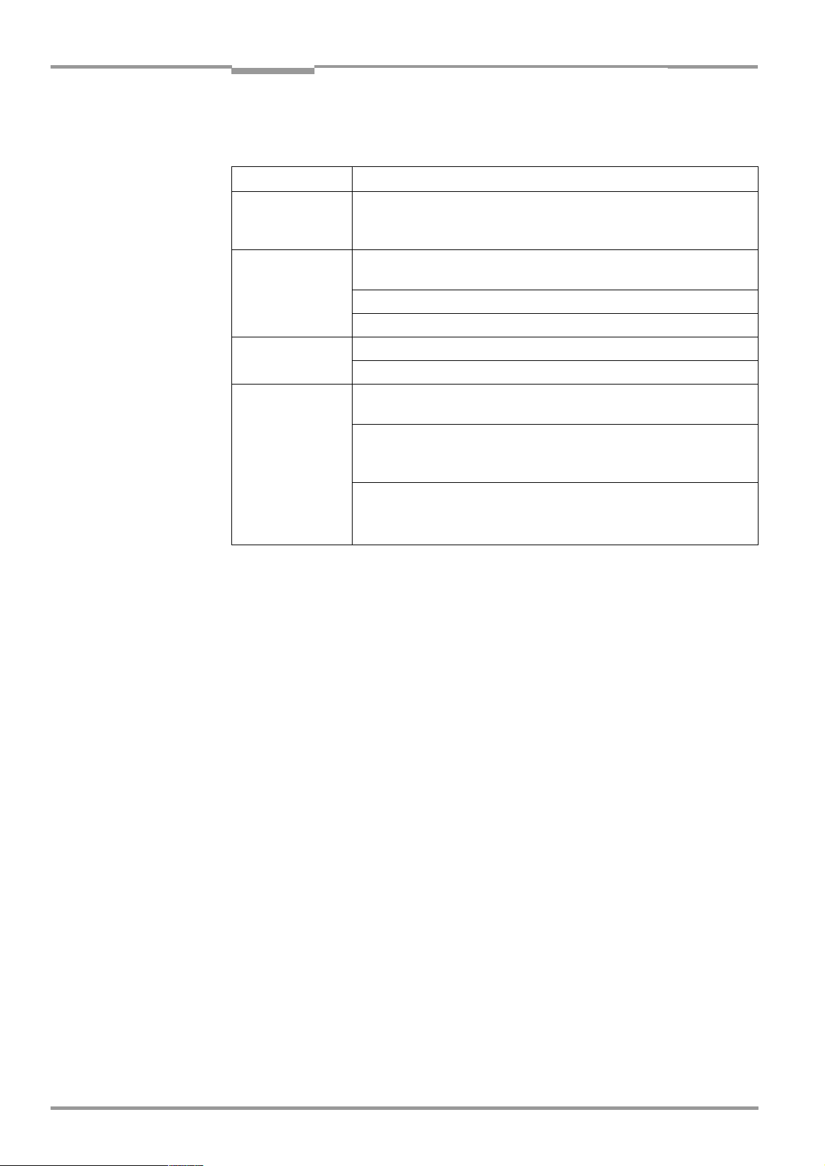
Fig. 4-1: Position of the threaded holes
Fig. 4-2: Reading distance to the object......................................................................................11
Fig. 4-3: 90 angle between the scan line and the bar code bars....................................12
Fig. 4-4: Reading angle occurring between the scan line and the bar code bars .......12
Fig. 4-5: Angle between the emitted light and the bar code
(tilted to the perpendicular).............................................................................................13
Fig. 4-6: Adjustment of the CLP 100 in order to avoid reflections;
a: With front-end light emission, b: With side-end light emission .....................13
Fig. 4-7: Installation site for the reading-pulse sensor and the reflector
(b smaller than a)................................................................................................................14
Fig. 5-1: Wiring the host interface .................................................................................................. 17
Fig. 5-2: Wiring the terminal interface ...........................................................................................18
Fig. 5-3: Wiring of the "Sensor" switching input........................................................................18
Fig. 5-4: Wiring of the "Result" switching output (NPN) .........................................................19
Fig. 6-1: Bar code sample (code 39, 0.35 mm, printing ratio 2:1)...................................21
Fig. 6-2: Terminal emulator with input of a command string ............................................... 23
Fig. 6-3: Terminal emulator with reading results of the CLP 100
in diagnosis mode...............................................................................................................25
Fig. 7-1: CLP 100 with front-end reading window (a) and
side-end reading window (b) .......................................................................................... 26
Fig. 9-1: Dimensions of the CLP 100 with front-end light emission in mm....................32
Fig. 9-2: Dimensions of the CLP 100 with side-end light emission in mm..................... 32
Fig. 10-1: User interface of the CLP Setup software ................................................................. 36
Fig. 10-2: Reading area diagram .......................................................................................................38
Fig. 10-3: Calculation example: Number of scans for ladder positioning
of the bar code bars ..........................................................................................................39
Fig. 10-4: Calculation example: Number of scans for fencing positioning
of the bar code bars ..........................................................................................................39
!
at CLP 100 .........................................................11
4
©
SICK AG · Division Auto Ident · Germany · All rights reserved 8 008 912/0000/21-08-2002
Page 5

Operating Instructions Chapter 1
CLP 100 Bar Code Reader
Notes on this document
1
Notes on this document
1.1 Function
This document instructs you on using the CCD bar code reader CLP 100.
It contains information on
•
Device installation and electrical installation
•
Startup
•
Operation and configuration (parameterization)
•
Maintenance
1.2 Target audience
The target audience for this document consists of electricians, service technicians and
engineers.
1.3 Information content
This document contains all the information required for the installation, electrical installation
and startup of the bar code reader CLP 100 with the default setting in our works.
All actions are described step-by-step.
Parameterization of the CLP 100 for the application-specific reading configuration is
carried out with the CLP Setup user interface. Installation and use of the software are
described in the appendix.
Further information on the construction of the bar code reader as well as the bar code
technology can be obtained from SICK AG, Auto Ident Division.
2
1.4 Symbols used
Some information in this document is emphasized.
Note A "Note" informs on exceptional features.
Recommendation A "Recommendation" provides information on how to carry out an action optimally.
Hint A "Hint" explains the setting possibilities in the CLP Setup software.
HIS FONT
T
example, menu item, tab card).
characterizes a term used in the user interface of the CLP Setup software (for
Safety information
2.1 Authorized users
The CLP 100 must be installed and operated by qualified personnel in order to ensure that
it functions correctly and safely. The following qualifications are required for the various
activities:
Installation and maintenance
•
Practical electrical training
•
Knowledge of the common safety instructions at the workplace
8 008 912/0000/21-08-2002 © SICK AG · Division Auto Ident · Germany · All rights reserved
5
Page 6

Chapter 2 Operating Instructions
Safety information
CLP 100 Bar Code Reader
Electrical installation and replacing devices
•
Practical electrical training
•
Knowledge of the common electrical safety instructions
•
Knowledge of the operation and handling of the devices of the respective application
(for example, packaging machines, clinical automatic analyzer, access control)
Startup, operation and configuration
•
Knowledge of the operation and handling of the devices of the respective application
(for example, packaging machines, clinical automatic analyzer, access control)
•
Basic knowledge of Windows 95™, Windows 98™ or Windows NT
•
Basic knowledge of a HTML browser (for example, Netscape Navigator
•
Basic knowledge of serial data transmission
•
Basic knowledge of bar code technology
™
™)
2.2 Intended use
The CLP 100 is used for the automatic detection and decoding of bar codes. It is installed
as a reading station and reads, for example, bar codes on objects of a clinical automatic
analyzer. The CLP 100 transmits the decoded bar code information via its host interface to
a host computer for further processing.
The user forfeits any warranty claims against SICK AG in case of any other use as well as in
case of changes to the device, also during device installation and electrical installation .
2.3 General safety instructions
¾
Read the general safety instructions thoroughly and observe them strictly at all activities
at the bar code reader. This also applies to the warnings before the handling instructions
in the individual chapters of this document.
LED lighting can endanger your eyes!
The CLP 100 uses an LED illumination line.
Light emitting diode class 1 according to EN 60825-1:A2:2001.
The retina can be damaged if you look too long into the beam.
¾
Do not look directly into the LED illumination line.
¾
Observe the most recent specifications of DIN EN 60825-1, latest version.
2.4 Quick- Stop and Quick-Restart
2.4.1 Switching off the CLP 100
¾
Switch off the supply voltage.
At the most the last read result is lost.
2.4.2 Switching on the CLP 100 again
¾
Switch on the supply voltage.
The CLP 100 resumes operation with the last parameter set saved.
©
6
SICK AG · Division Auto Ident · Germany · All rights reserved 8 008 912/0000/21-08-2002
Page 7
Operating Instructions Chapter 3
CLP 100 Bar Code Reader
Product description
2.5 Environmental information
The CLP 100 is designed so that it harms the environment as little as possible. It does not
contain or emit any substances harmful to the environment and is not a source of faults for,
for example, coating wetting in paint shops.
The maximum power consumption of the CLP 100 amounts to 2 W.
2.5.1 Disposal after final removal from service
Dispose of unusable or irreparable devices in accordance with the respective state
regulations on waste disposal in a manner compatible with the environment. The CLP 100
design allows it to be separated into recyclable secondary raw materials (housing) and
hazardous waste (electronic scrap).
does not take back devices which have become unusable or irreparable.
Also refer to Section 7.3, Page 27
. At present, SICK AG
3
Product description
3.1 Design
3.1.1 Scope of delivery
The packing of the CLP 100 contains the following:
•
One bar code reader CLP 100
•
One information sheet (notes on device) with connection diagram and Quick-Start
Depending on the number of devices ordered one or more of the following are included:
•
These CLP 100 operating instructions in English and German
•
A set of DOS-formatted diskettes (3.5") containing the CLP Setup operating software for
Windows™, the CLP Setup Help on-line help system and the HTML browser I-ViewPro
3.1.2 Variants
At present the CLP 100 is available in the following variants:
Device Light emission Connection
CLP 100-0010 Front 9-pin D-Sub plug
CLP 100-2010 Side 9-pin D-Sub plug
CLP 100-0110 Front Open cable end
CLP 100-2110 Side Open cable end
™
Tab. 3-1: Variants of the CLP 100
3.1.3 System requirements
The following are required to start-up and operate the CLP 100:
•
A public supply system device with an output voltage of 5 V DC ± 5 % in accordance with
IEC 742 (functional extra-low voltage) and at least 2 W power output
•
In the case of external reading pulsing via the "Sensor" switching input: A suitable sensor
for signaling an object with bar code, for example, a reflection photoelectric switch
•
A PC with Windows 95™, Windows 98™ or Windows NT™ and a serial interface
("COM x" port)
•
An RS-232 data connection cable (TxD and RxD transposed)
•
In order to use a CLP Setup Help on-line help system an HTML browser, for example,
Netscape Navigator™ or the enclosed I-ViewPro™ (
delivery
8 008 912/0000/21-08-2002 © SICK AG · Division Auto Ident · Germany · All rights reserved
)
refer to Section 3.1.1 Scope of
7
Page 8
Chapter 3 Operating Instructions
Product description
CLP 100 Bar Code Reader
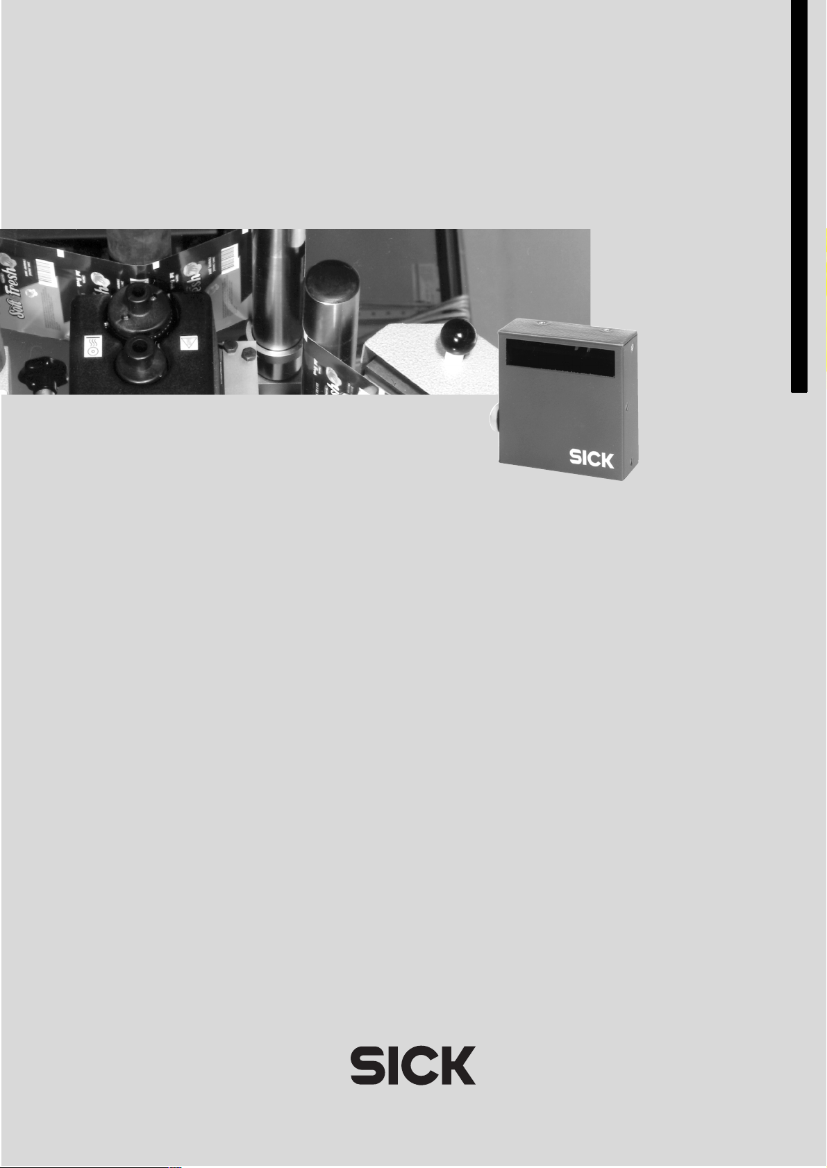
3.1.4 Design
!! " § !!
Legend:
!
Threaded hole M 3, 5 mm deep
"
Connection cable
§
Reading window
$
LED (status display)
Fig. 3-1: Design of the CLP 100 with face-end light emission
$
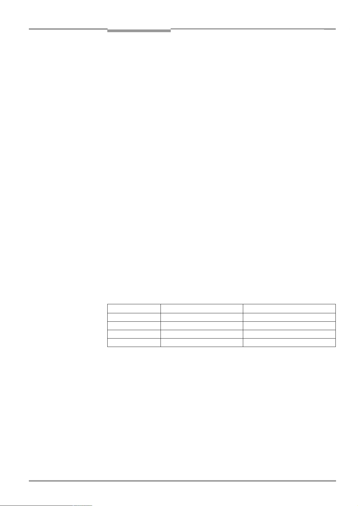
!! " § !! $
Legend:
!
Threaded hole M 3, 5 mm deep
"
Connection cable
§
Reading window
$
LED (status display)
Fig. 3-2: Design of the CLP 100 with side light emission
©
8
SICK AG · Division Auto Ident · Germany · All rights reserved 8 008 912/0000/21-08-2002
Page 9
Operating Instructions Chapter 3
CLP 100 Bar Code Reader
Product description
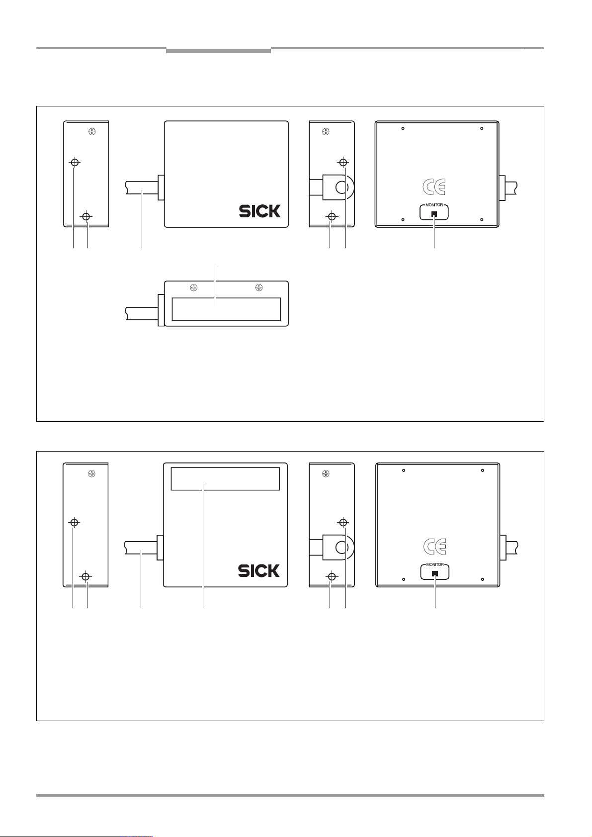
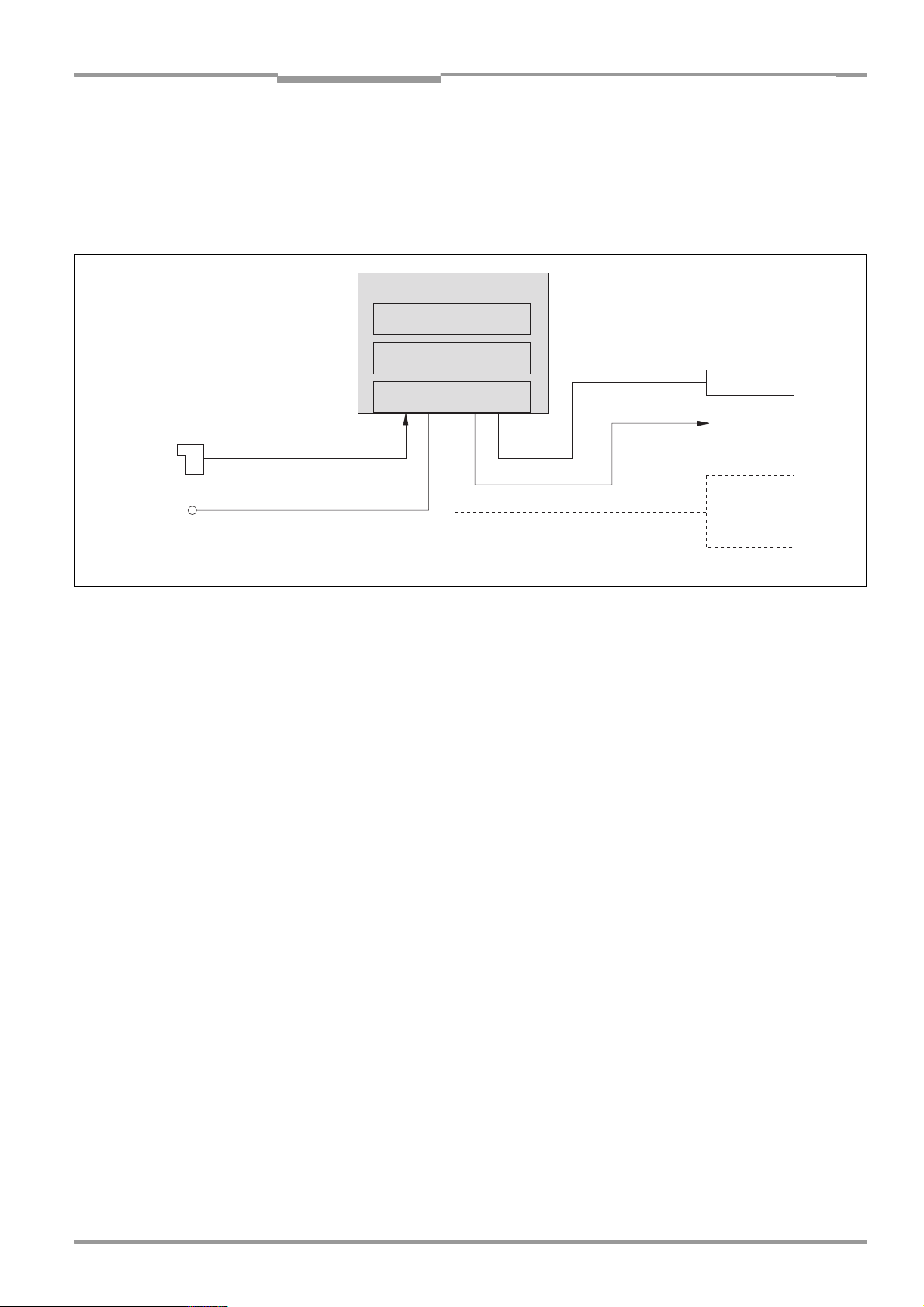
3.2 Working method of the device
The CCD bar code reader CLP 100 detects bar codes in an illuminated scan field (scan line)
and decodes the bar codes. The CLP 100 transmits this data via the serial host interface to
a host/PC for further processing. Refer to
the CLP 100.
CLP 100
CCD line with lighting
Decoder
Figure 3-3
for an overview of the functionality of
Photoelectric
switch
Reading
pulse
DC 5 V ± 5 %
Fig. 3-3: Function of the CLP 100
Host
Result function
e.g. Good Read/
No Read
PC
--- Cable if required
"Sensor
Interface
"
"Host"
"Result"
"Terminal"
The CLP 100 derives useful data for diagnostics from the reading processes. The quality of
the reading data can be checked in the diagnosis mode.
The CLP 100 requires suitable pulsing (triggering) in order to start a reading process when
there is an object in the reading area. This results in a time window for the reading process
being opened in the CLP 100. Triggering is carried out either with an external sensor or with
a command string via the host interface. Both options are active in the default setting.
The switching input ("Sensor" input) informs the CLP 100 when it must start a reading
process. The switching output ("Result" output) can have result functions assigned to them
and triggers external devices such as, for example, a PLC input.
3.3 Display and operating elements
The CLP 100 is operated or parameterized via the host interface by using the CLP Setup
PC software or with command strings. The CLP 100 is adapted to various applications by
means of parameterization. The CLP Setup software is used, for example, to carry out the
following settings:
•
Configuration of the code types to be read
•
Read, evaluation and output properties
•
Communication parameters of the host interface
•
Structure of the data output strings of the host interface
•
Function of the auxiliary interface (terminal interface)
Section 10.2, Page 33
The procedure for parameterizing the CLP 100 with the software is explained in
Page 21
.
An LED status display ("Monitor") with two LEDs (red and green) on the rear of the CLP 100
indicates the current operating state of the device. The meaning of the display for the
8 008 912/0000/21-08-2002 © SICK AG · Division Auto Ident · Germany · All rights reserved
describes the installation and handling of the CLP Setup software.
Section 6.5,
9
Page 10
Chapter 4 Operating Instructions
Installation
CLP 100 Bar Code Reader
respective operating mode is shown in
Table 3-2
. The display can be parameterized
differently in some operating modes. The table lists all the possible meanings.
:
Operating mode Display Function
Start Green/
red
Reading mode Green/
red
Green
Red
Adjusting mode Green
Red
Matchcode
operation
Green/
red
Red
Green
•
Light up during the switching on phase if the self-test is
successful
•
Extinguish when changing to the read standby state
•
Light up when the signal for reading is given, until the
beginning of the next reading cycle
•
Lights up after successful reading ("Good Read")
•
Extinguishes after successful reading ("Good Read")
•
Extinguishes after unsuccessful reading ("No Read")
•
Lights up after unsuccessful reading ("No Read")
•
Extinguish, when there was no signal for reading and there
is no read result
•
Lights up at "No Read" or "Read & No Match"
or in accordance with the parameterization
•
Lights up at "No Read" or "Read & Match"
•
Lights up at "Read & Match"
or in accordance with the parameterization
•
Lights up at "Read & No Match"
4
Installation
Tab. 3-2: Meaning of the LEDs
4.1 Installation sequence
•
Select the installation site for the CLP 100
•
Connect the power supply
•
Align the CLP 100 to the bar code
•
Install the CLP 100
•
Adjust the CLP 100
•
Install the external sensor for the reading pulse
4.2 Preparations for installation
4.2.1 Laying out the components to be installed ready
•
CLP 100 bar code reader
4.2.2 Laying out the required tools ready
•
2 screws for fixing the CLP 100 to the installation site
Screw diameter: 3 mm,
Screw length depends on the wall thickness of the base.
Screws may not be screwed more than 2.5 mm into the CLP 100
•
Tool
•
Measuring tape
•
Angulometer
10
©
SICK AG · Division Auto Ident · Germany · All rights reserved 8 008 912/0000/21-08-2002
Page 11
Operating Instructions Chapter 4
!! !!
CLP 100 Bar Code Reader
Installation
4.2.3 Selecting the installation site
When selecting the installation site take the distance between the CLP 100 and the host as
well as the distance between the CLP 100 and the bar code into consideration. The angle
between the scan line and bar code is selected, so that a good reading is possible. The
optimal setting of the angle is described further below.
The CLP 100 is fastened by means of two threaded holes (M 3) to the top or bottom of the
device (
Page 32
refer to Figure 4-1
.
). The complete housing dimensions are shown in
Section 9.2,
Fig. 4-1: Position of the threaded holes !at CLP 100
Distance between the CLP 100 and the host
The maximum distance between the CLP 100 and the host when extension cables are used
amounts to 12 m (host interface RS-232).
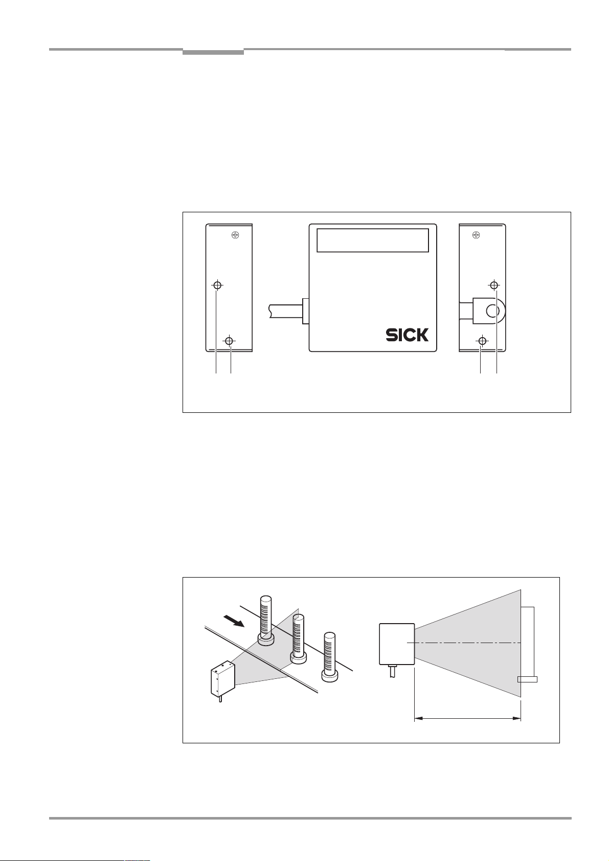
Distance between the CLP 100 and the bar code
The distance a between the reading window of the CLP 100 and the bar code must amount
to 20 to 70 mm depending on the width of the bar code (
Page 38
distance for various resolutions (module widths).
shows the width of the reading area of the CLP 100 in relation to the reading
refer to Figure 4-2
Section 10.3,
).
Fig. 4-2: Reading distance to the object
8 008 912/0000/21-08-2002 © SICK AG · Division Auto Ident · Germany · All rights reserved
a
11
Page 12
Chapter 4 Operating Instructions
Installation
CLP 100 Bar Code Reader
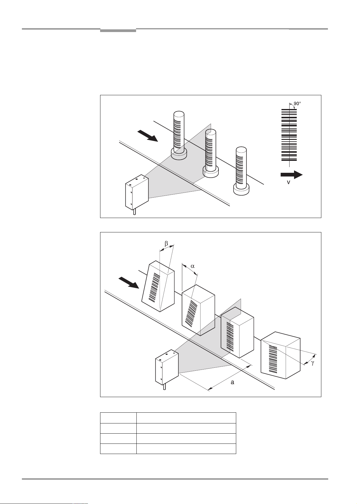
Angle alignment of the CLP 100
The optimum alignment of the CLP 100 is reached at an angle of 90° between the scan line
and the bar code bars (
between the scan line and the bar code bars must be taken into consideration (
Figure 4-4 and Table 4-1
refer to Figure 4-3
).
). Possible reading angles which can arise
refer to
Fig. 4-3:
angle between the scan line and the bar code bars
90
°
12
Fig. 4-4: Reading angle occurring between the scan line and the bar code bars
Angle Limit
α
Tilt
β
Pitch
γ
Skew
Tab. 4-1: Permissible angle occurring between the scan line and the bar code bars
©
SICK AG · Division Auto Ident · Germany · All rights reserved 8 008 912/0000/21-08-2002
0° ± 2
0° ± 5
10° ± 5
°
°
°
Page 13
Operating Instructions Chapter 4
5
°
CLP 100 Bar Code Reader
Installation
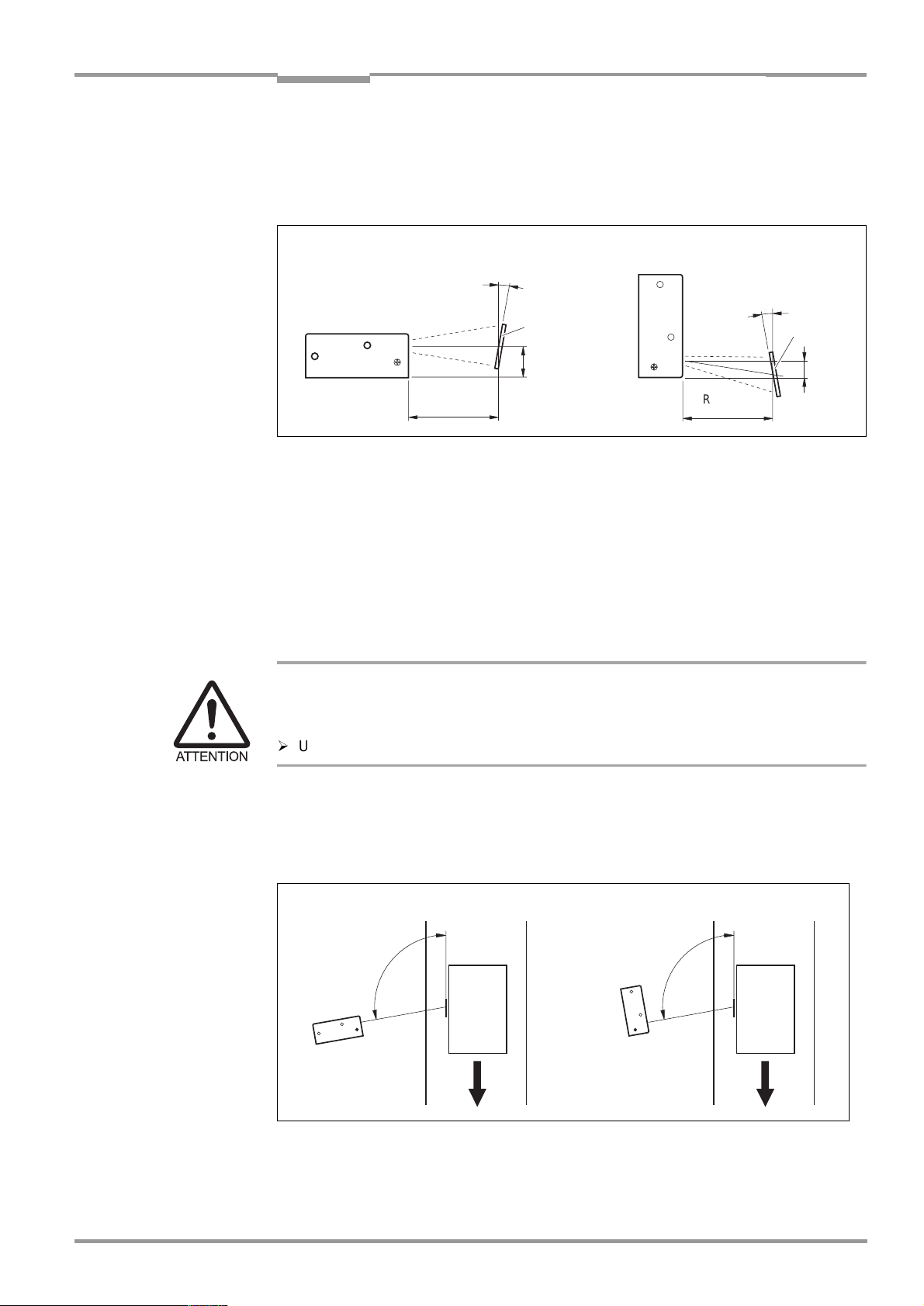
Note If the light of the scan line falls exactly vertically on the surface of the bar code, disturbing
reflections can occur when the reflected light is received. In order to avoid this effect the
CLP 100 must be installed so that the emitted light is tilted relative to the perpendicular
refer to Figure 4-5
(
Front-end light emission Side-end light emission
).
10°
10°
Bar code
Bar code
15
Reading
Distance
Fig. 4-5: Angle between the emitted light and the bar code (tilted to the perpendicular)
Reading
Distance
8
4.3 Installation and adjustment of the device
4.3.1 Installing the CLP 100
1. Align the CLP 100 so that the angle between the scan line and the bar code bars
amounts to 90°. Take any possible reading angle occurring into consideration (
Figure 4-4
).
2. In orde r to av oid d i s turbi ng ref lection s ali gn the C LP 10 0 so tha t the e mitt e d ligh t impa c ts
on the bar code at an angle of 100
° respectively 95°
refer to Figures 4-5 and 4-6
(
Damage to the housing
The screws may not be screwed more than 5 mm into the CLP 100. Longer screws may
damage the housing.
¾
Use screws with a suitable length.
3. Screw the screws through the base to which the CLP 100 is fastened into the threaded
hole.
4. Tighten the screws slightly.
5. Adjust the CLP 100 as described below.
refer to
).
ab
100°
Fig. 4-6: Adjustment of the CLP 100 in order to avoid reflections;
a: With front-end light emission, b: With side-end light emission
8 008 912/0000/21-08-2002 © SICK AG · Division Auto Ident · Germany · All rights reserved
95
100°
°
13
Page 14
Chapter 4 Operating Instructions
Installation
CLP 100 Bar Code Reader
4.3.2 Adjusting the CLP 100
The adjusting operating mode supports the adjustment of the CLP 100. In this operating
mode the green LED extinguishes if the reading process fails ("No Read"). If the green LED
does not light up, the CLP 100 cannot read the bar code. If the green LED flickers, the CLP
100 can only read the bar code badly. If the green LED shows steady light, the CLP 100 is
aligned optimally. The scanning frequency in adjusting mode amounts to 500 Hz.
1. Connect the CLP 100 to the supply voltage and switch on the supply voltage.
2. Connect the CLP 100 to the PC.
3. Call up the CLP Setup user interface (
4. In the CLP Setup select the D
5. Click in the O
6. Click in the LED
PERATING MODE
DISPLAY
EVICE CONFIGURATION
field and select A
field and select NO R
7. Carry out the download to the CLP 100 (
refer to Section 10.2, Page 33
tab card.
DJUSTING MODE
EAD/GOOD READ
.
.
refer to Section 6.5.1, Page 21
).
).
8. Guide objects with bar codes realistically into the reading area of the CLP 100. Ensure
that the permitted reading angle is not exceeded.
9. Start the reading pulse: Cover the optical path of the sensor or make connection (
to Section 4.4
).
refer
10. Align the CLP 100 so that the green LED lights up steadily as far as possible (reading
result "Good Read").
11. Tighten the screws.
The CLP 100 is aligned optimally to the bar code.
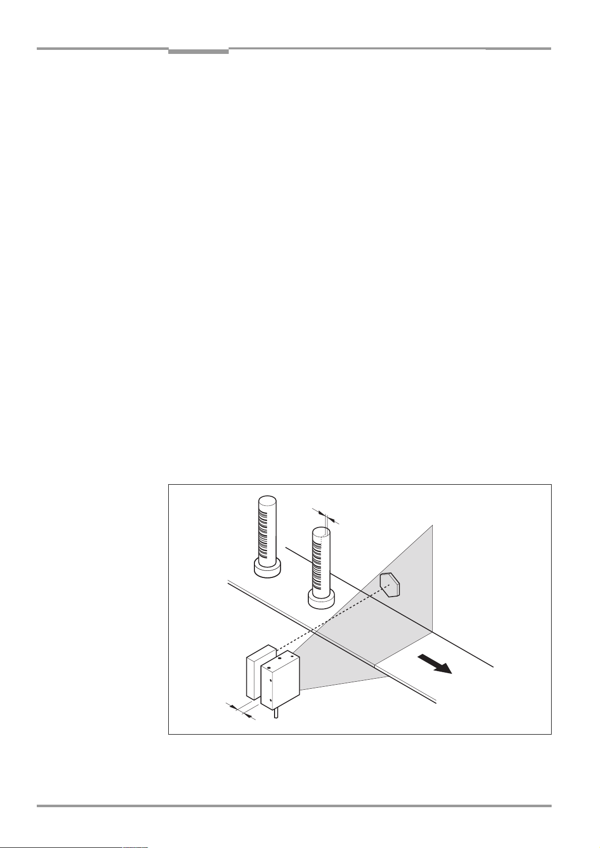
4.4 Installing the reading-pulse sensor
If the CLP 100 is triggered via an external sensor, the sensor and a reflector have to be
installed near the CLP 100.
sensor.
Figure 4-7
shows an example of the installation site of the
a
14
b
Fig. 4-7: Installation site for the reading-pulse sensor and the reflector (b smaller than a)
©
SICK AG · Division Auto Ident · Germany · All rights reserved 8 008 912/0000/21-08-2002
Page 15

Operating Instructions Chapter 5
CLP 100 Bar Code Reader
Electrical installation
1. Install the reading-pulse sensor at the installation site.
2. Connect the reading-pulse sensor to the CLP 100 (
3. Call up the CLP Setup and check the read result with the terminal emulator (
Section 6.5, Page 21
).
refer to Section 5.4.5, Page 18
refer to
).
4. Check whether the reading process of the CLP 100 is synchronized with the incoming
objects.
4.5 Disassembling the device
1. Switch off the supply voltage.
2. Disconnect the cable connection.
3. Screw off the CLP 100.
4. Dispose of the CLP 100 ecologically friendly (
refer to Section 7.3, Page 27
).
5
Electrical installation
5.1 Electrical connections
The electrical connection of the CLP 100 is carried out either via a 9-pin D-Sub cable plug
or the open cable end.
5.2 Pin assignment of the connection plug or wire colors of
1
6
Pin Signal
1Sensor
2RxD (Host)
3TxD (Host)
4 Result "GO/NG"
5 GND
6 Not assigned
7 RxD (Terminal), TTL
8 TxD (Terminal), TTL
9
the cable end
5
9
+
5 V
Tab. 5-1: Pin assignment of the connection plug
8 008 912/0000/21-08-2002 © SICK AG · Division Auto Ident · Germany · All rights reserved
15
Page 16

Chapter 5 Operating Instructions
Electrical installation
Wire color open
cable end Signal
Pink Sensor
Brown RxD (Host)
Gray TxD (Host)
White Result "GO/NG"
Black GND
Yellow RxD (Terminal), TTL
Orange TxD (Terminal), TTL
Red
Blue RTS
Green CTS
Tab. 5-2: Assignment of the wire colors of the cable end
+
5 V
CLP 100 Bar Code Reader
5.3 Planning the electrical installation
5.3.1 Requirements for the host interface
The host interface of the CLP 100 is operated as an RS-232 interface. For the pin
assignment refer to
Table 5-3
shows the recommended maximum cable lengths as a function of the data
Table 5-1 or Table 5-2.
transmission rate.
.
Interface type Transmission rate Max. distance to the host
RS-232 Up to 19,200 Bd 12 m
Tab. 5-3: Maximum cables lengths between the CLP 100 and the host
Recommendation In order to avoid interferences, do not lay the cable parallel to the power-supply and motor
cables (for example in cable ducts).
5.3.2 Supply voltage
±
For operation the CLP 100 requires a supply voltage of 5 V DC
5 % in accordance with
IEC 742 (functional extra-low voltage). The power supply unit must also fulfil IEC 742 and
output a continuous output of 2 W.
5.4 Carry out the electrical installation
5.4.1 Installation steps
•
Connecting the supply voltage
•
Wiring the host interface (Connecting the PC)
•
Wiring the "Sensor" switching input
•
Wiring the "Result" switching output
16
5.4.2 Connecting the supply voltage
¾
Connect the supply voltage to Pin 5 and Pin 9 of the 9-pin plug (
Page 15
©
SICK AG · Division Auto Ident · Germany · All rights reserved 8 008 912/0000/21-08-2002
).
refer to Table 5-1,
Page 17

Operating Instructions Chapter 5
CLP 100 Bar Code Reader
Electrical installation
5.4.3 Wiring the host interface (Connecting the PC)
The CLP 100 is operated and configured with the CLP Setup software. For this purpose it
must be connected to the PC via the host interface.
When the PC is connected, the communications parameters are set as described in
Section 6.5.1, Page 21
Figure 5-1
Fig. 5-1: Wiring the host interface
shows the wiring of the RS-232 host interface.
.
*) 9-pin internal D-Sub plug to PC
Recommendation
Damage to the interface module in the CLP 100!
Electronic components in the CLP 100 can be damaged if the host interface is wired
incorrectly.
¾
Wire the host interface correctly in accordance with
¾
Check the wiring before switching on the CLP 100.
¾
Connect the host interface of the CLP 100 EMC-compatibly to the host by means of
shielded cables (
Table 5-3, Page 16
¾
Apply the shielding at one end.
refer to Figure 5-1
).
). Observe the maximum cable lengths (
Figure 5-1
.
refer to
1. Switch off the PC and the supply voltage of the CLP 100.
2. Connect the desired port "COM x" of the PC to the CLP 100. To this purpose use an
RS-232 data connection cable (RxD and TxD transposed).
3. Switch on the PC and the supply voltage of the CLP 100.
4. Set the communication parameters of the PC (
refer to Section 10.2.3, Page 34
).
In the default setting the CLP 100 communicates via the RS-232 interface with the host
using the values listed in
Parameter Host interface value Terminal interface value
Data transmission
rate
Table 5-4
9,600 Bd 9,600 Bd
.
Data bit 8 8
Parity None None
Stop bit 1 1
Protocol SICK:
Sending start characters: STX
Sending stop characters: ETX
Repeat request: None
Timeout: 50 ms
Tab. 5-4: Communication parameters of the host interface (default setting)
8 008 912/0000/21-08-2002 © SICK AG · Division Auto Ident · Germany · All rights reserved
SICK:
Sending start characters: STX
Sending stop characters: ETX
Repeat request: None
Timeout: 50 ms
17
Page 18

Chapter 5 Operating Instructions
2.4 V VS5 V
≤≤
Electrical installation
CLP 100 Bar Code Reader
5.4.4 Wiring the terminal interface
As an alternative the PC may be connected to the terminal interface.
Figure 5-2
shows the wiring of the terminal interface.
Note The terminal interface is a TTL level interface.
7 3 *
8 2 *
5 5 *
*) 9-pin internal D-Sub plug to PC
Fig. 5-2: Wiring the terminal interface
5.4.5 Wiring the "Sensor" switching input
If a reading process is to be triggered via an external sensor, connect the sensor to the
"Sensor" switching input. This triggering type is selected as the default setting of the CLP
100.
Figure 5-3
shows the wiring of the "Sensor" switching input.
Table 5-5
lists the
characteristic data of this switching input.
5 V
CLP 100
Fig. 5-3: Wiring of the "Sensor" switching input
¾
Connect the sensor as described in
Switching
Connecting GND to the input starts the read port of the CLP 100 (low)
performance
Properties Not electrically separated
Electrical values Low
(Read port active):
≤≤
0 V VS0.8 V
≤
I1.5 µA
Tab. 5-5: Characteristic data of the "Sensor" switching input
Hint The D
EVICE CONFIGURATION
tab card of the CLP Setup software can be used to modify the
response time of the "Sensor" input (debouncing).
"Sensor"
GND
Figure 5-3
1
5
.
High
(Read port inactive):
≤
I1.5 µA
Sensor
18
©
SICK AG · Division Auto Ident · Germany · All rights reserved 8 008 912/0000/21-08-2002
Page 19

Operating Instructions Chapter 6
CLP 100 Bar Code Reader
Operation
5.4.6 Wiring the "Result" switching output
The switching output can have various result functions assigned to it. If the corresponding
event occurs during a reading process, the switching output becomes live for the selected
pulse duration.
the characteristic data of the switching output.
Fig. 5-4: Wiring of the "Result" switching output (NPN)
Figure 5-4
shows the wiring of the "Result" switching output.
Table 5-5
lists
6
Recommendation
Hint The D
Operation
¾
In order to check the switching functions wire the switching output to a load and measure
the voltage with a high-voltage digital voltmeter. This avoids the display of incorrect
voltage values and switching states.
¾
Wire the switching output as described in
Switching performance NPN switching against GND
Properties Not electrically separated
Electrical values
Tab. 5-6: Characteristic data of the "Result" switching output
EVICE CONFIGURATION
function assignment, the pulse duration and the output instant of the signal.
≤≤
5V U 30V
≤
I50mA
tab card of the CLP Setup software can be used to modify the
Figure 5-4
.
6.1 Startup steps
•
Startup of the CLP 100 with the default setting set by factory (Quick-Start).
The CLP 100 can be operated without a connection to the PC in this configuration.
•
Connecting the PC (
refer to Section 10.2, Page 33
(
•
Parameterizing of the CLP 100 with the CLP Setup software or with command strings.
refer to Section 5.4.4, Page 18
).
) and installing the CLP Setup software
6.2 Default setting
Table 6-1
parameters in the default setting are selected so that the CLP 100 can be used directly for
many applications in this configuration. With the default setting no PC is required for starting
up.
8 008 912/0000/21-08-2002 © SICK AG · Division Auto Ident · Germany · All rights reserved
shows an overview of the default setting of our works for the CLP 100. The
19
Page 20

Chapter 6 Operating Instructions
Operation
CLP 100 Bar Code Reader
Parameter Default setting
Active code type Code 39
Code length Free
Multiple reading 2
Number of codes 1
Reading direction Both
Send start/stop characters Not active
Check digit None
Reading pulse generation Active low (unchangable)
Switching output Not active
Host interface RS-232 (unchangable)
Protocol Start characters STX, Stop characters ETX
Data transmission rate 9,600 Bd
Data format 8 data bits, no parity, 1 stop bit
Output instant Immediately
No Read message BR
Tab. 6-1: Default setting of the parameters of the CLP 100
If the CLP 100 is connected to a PC, the current parameters can be changed by using the
CLP Setup software. The parameter set of the default setting is saved in the CLP Setup and
in the CLP 100 and can be re-activated at any time.
The complete default setting can be viewed by using the CLP Setup software and printed
out, if required:
1. In order to save the current settings: Select the S
AVE AS
menu item in the F
ILE
menu bar
and enter the file name.
2. Click on in the toolbar.
The default setting is loaded and is displayed in the tab cards.
3. Click on in the toolbar.
ILE PRINT
The F
dialog box is opened.
4. Enter the comment for the header of the output and click on OK.
The dialog box for the print settings is opened.
5. Enter the settings for printing and click on OK.
CLP Setup prints out the default settings.
6.3 Quick-Start
20
1. Carry out the electrical installation in accordance with
Chapter 5, Page 15.
A PC does not
have to be connected if the CLP 100 is operated with the default setting.
2. Switch on the supply voltage.
The LEDs of the CLP 100 light up and are extinguished after the self-test has been
completed successfully.
3. Present the bar code sample from
Figure 6-1
to the CLP 100 at a distance of approx.
35 mm.
4. Start the reading pulse: Cover the optical path of the sensor (close the switch).
Both LEDs light up.
©
SICK AG · Division Auto Ident · Germany · All rights reserved 8 008 912/0000/21-08-2002
Page 21

Operating Instructions Chapter 6
CLP 100 Bar Code Reader
Operation
5. End the reading pulse: Unmask the optical path of the sensor (open the switch).
If the reading has been successful, the red LED is extinguished, the green LED lights up.
The CLP 100 is ready to operate with the default setting of our works.
The CLP 100 can be switched off without the configuration data being lost, since no changes
were carried out to the parameter set.
0123412345
Fig. 6-1: Bar code sample (code 39, 0.35 mm, printing ratio 2:1)
6.4 Operating modes and output of the read result
When parameterizing the CLP 100, it is possible to choose between the following operating
modes:
•
Reading mode
•
Diagnostic mode
•
Adjusting mode
•
On-line test mode
reading mode
In
the end of the reading pulse via the host and terminal interface.
diagnosis mode
In
statistically into the read field of the CLP (no transport movement). The output is emitted via
the host and terminal interface. For details on the diagnosis mode
Page 24
In
In the
and not via the host interface.
When outputting the read result, it is possible to choose between the normal reading
function and the code comparison function (matchcode). The matchcode function allows
the comparison of the read bar codes with a code which is entered at the CLP 100. It is
possible to select between complete or partial matching of the codes.
.
adjusting mode
on-line test mode
the CLP 100 detects the presented bar codes and emits the read result at
the quality of the bar code readings is judged. These are brought
refer to Section 6.5.8,
the CLP 100 is adjusted to the bar code (
the CLP 100 emits the read result only via the terminal interface
refer to Section 4.3.2, Page 14
).
6.5 Parameterization
The CLP 100 is adapted to the specifc applications by means of the parameterization.
Parameterization is carried out either with the CLP Setup software or with command strings.
To this purpose a PC has to be connected and the CLP Setup has to be installed. Connection
of the PC to the CLP 100 is described in
of the CLP Setup software are described in the appendix (
6.5.1 Transferring the parameter set between the CLP Setup and CLP 100
In order to edit the current parameter set of the CLP 100 it must first be copied from the
CLP 100 to the CLP Setup. This process is designated as uploading.
Changes to the parameter set carried out in the CLP Setup are not effective until they have
been transferred to the CLP 100. CLP Setup always copies the complete parameter set.
Saving the parameters to the CLP 100 is designated as downloading.
8 008 912/0000/21-08-2002 © SICK AG · Division Auto Ident · Germany · All rights reserved
Section 5.4.4, Page 18
. Installation and handling
Section 10.2, Page 33
).
21
Page 22

Chapter 6 Operating Instructions
Operation
CLP 100 Bar Code Reader
Uploading the parameter set from the CLP 100
¾
Click on in the CLP Setup toolbar.
CLP Setup copies the parameter set last saved in the CLP 100 from the CLP 100 into its
database and displays its values in the tab cards.
If the CLP Setup software does not recognize the loaded parameters during uploading, a
warning is emited. Unknown parameters can be edited in the terminal emulator under
observance of the conventions for command strings. These parameters are also taken into
consideration when the parameter set is saved.
Downloading the parameter set to the CLP 100
¾
Click on in theCLP Setup toolbar.
The new parameter set is saved in the CLP 100.
Saving the parameter set in the CLP Setup
1. Select the S
AVE AS
menu item in the F
ILE
menu bar in order to save the modified
parameter set as the new configuration file in the CLP Setup or to overwrite an existing
file.
The S
AVE
CLP
FILE
dialog box is opened.
2. Enter the path and file name in the dialog box (extension of the file name: "*.scl") and
click on OK.
The new parameter set is saved in the CLP Setup.
6.5.2 Parameterize the CLP 100 with command strings
The CLP 100 can be parameterized for example by means of the terminal emulator by
entering command strings. Parameters which are unknown to the CLP Setup can also be
used.
The command language of the CLP 100 accesses the command interpreter of the device
directly.
Figure 6-2
shows a view of the terminal emulator. A0 is entered as an example in
the framed text field for entering commands. This input is repeated in the large output
window. For a full description of the command language refer to
Table 10-3, Page 41.
1. Click on in the CLP Setup toolbar.
The terminal emulator window opens.
2. Enter the command in the framed text field and press the Return key.
The command is transmitted to the CLP 100.
Note The CLP 100 does not transmit an answer, but reacts immediately to the command.
22
©
SICK AG · Division Auto Ident · Germany · All rights reserved 8 008 912/0000/21-08-2002
Page 23

Operating Instructions Chapter 6
CLP 100 Bar Code Reader
Operation
Fig. 6-2: Terminal emulator with input of a command string
6.5.3 Selecting reading mode
After being switched on the CLP 100 carries out a self-test and then changes over to the
reading mode (default setting). Reading mode can be selected as follows if the CLP 100 is
in another operating mode:
1. In the CLP Setup select the D
2. Click in the O
PERATING MODE
3. Carry out the download to CLP 100.
The CLP 100 is in reading mode.
6.5.4 Adjusting the reading pulse
In the CLP 100 default setting the reading pulse (trigger) is supplied by an external sensor.
Debouncing of the sensor and the type of reading pulse end (through a time window or a
sensor signal) can be set by means of the CLP Setup software.
1. In the CLP Setup select the D
2. Select the settings in the R
3. Carry out the download to CLP 100.
EVICE CONFIGURATION
field and select R
EVICE CONFIGURATION
EADING PULSE
or R
tab card.
EADING MODE
.
tab card.
EADING PULSE END
field.
8 008 912/0000/21-08-2002 © SICK AG · Division Auto Ident · Germany · All rights reserved
23
Page 24

Chapter 6 Operating Instructions
Operation
CLP 100 Bar Code Reader
6.5.5 Triggering the reading pulse
In its default setting the CLP 100 receives the reading pulse (trigger) via an external sensor
or a command string (software trigger). For test purposes, the reading pulse can also be
triggered directly via the terminal emulator.
1. Click on in the CLP Setup toolbar.
The terminal emulator window opens. The CLP 100 is in reading mode.
2. Click on S
TART READING
.
3. Present the bar code.
4. Click on S
TOP READING
.
The CLP 100 outputs the read result in the window of the terminal emulator.
6.5.6 Setting the structure of the read result
In its default setting the CLP 100 sends the data contents of the bar code to the host as
the read result. In the default setting this data string is STX-/ETX-framed.
The structure of the data string can be selected by means of the H
CONFIGURATION
1. In the CLP Setup select the R
2. Click in the S
3. Select the H
4. Click in the S
tab cards.
END PREFIX
OST INTERFACE
EPARATOR
EADING CONFIGURATION
tab card.
list box and select a prefix from the list (A-Z, 1-0).
tab card.
list field and select a separator.
OST INTERFACE
and R
EADING
5. Carry out the download to CLP 100.
The CLP 100 operates with the new settings.
6.5.7 Setting the matchcode function
The matchcode function allows the comparison of the read bar codes with a code which is
entered manually at the CLP 100 or trained in automatically (matchcode).
1. In the CLP Setup select the D
CTIVE
2. Click in the A
box in the C
3. Enter the code which is to be used for comparison in the M
4. If only a part of the code has to agree, enter the partial code in the P
OF THE MATCHCODE
text field, and complete the field with question marks or @ characters.
5. Selection the function of the switching output in the S
EVICE CONFIGURATION
OMPARE CODE
field.
tab card.
ATCHCODE
WITCHING OUTPUT AT CODE COMPARISON
text field.
ARTIAL COMPARISON
field.
6. Carry out the download to CLP 100.
The CLP 100 outputs a result either at agreement of the read codes with the matchcode
or at non-agreement.
6.5.8 Setting the diagnosis mode
In diagnosis mode the quality of the bar code readings is judged. These are brought
statistically into the read field of the CLP 100 (no transport movement). The CLP 100 carries
out 100 readings after the reading pulse and evaluates them.
The data string in the diagnosis mode is STX-/ETX-framed. The data string contains the bar
code information (data) at the first place, followed by a slash and a three-digit identifier. The
data string is followed by the combination of slash and identifier repeated thrice (a total of
four identifiers separated by slashes):
<STX>Data/www/xxx/yyy/zzz<ETX>.
24
©
SICK AG · Division Auto Ident · Germany · All rights reserved 8 008 912/0000/21-08-2002
Page 25

Operating Instructions Chapter 6
CLP 100 Bar Code Reader
Operation
The maximum value of an identifier is 100. If the value is lower (one- or two-digit number),
the leading blanks will be filled with spaces. If the D
ISPLAY CONTROL CODE
function is activated,
a space is displayed as <SPC>. The identifiers mean:
www = Number of successful readings ("Good reads")
xxx = Number of successful decoding processes (with misinterpretations)
yyy = Number of successful indentifications of a start or stop character (depending on
the scan direction)
zzz = Number of readings carried out (the CLP 100 carries out 100 readings each in
the diagnosis mode)
Error-free reading and decoding of a bar code would thus have the following form:
<STX>Data/100/100/100/100<ETX>.
A reading with some failed decodings has, for example, the following form:
<STX>Data/<SPC>67/<SPC>67/100/100<ETX>.
If the CLP 100 has only recognized the start character, it transfers a question mark instead
of the data string:
<STX>?/<SPC><SPC>0/<SPC><SPC>0/100/100<ETX>.
Figure 6-3
shows further examples of reading results in the diagnosis mode:
Fig. 6-3: Terminal emulator with reading results of the CLP 100 in diagnosis mode
8 008 912/0000/21-08-2002 © SICK AG · Division Auto Ident · Germany · All rights reserved
25
Page 26

Chapter 7 Operating Instructions
Maintenance
CLP 100 Bar Code Reader
The diagnosis mode can be selected directly in the terminal emulation window or set via the
tab cards:
¾
If the terminal emulator window is active: Click in the D
the bar code.
The reading process is started automatically. The CLP 100 scans the bar code once per
second.
- or -
1. If the terminal emulator window is not active: In the CLP Setup select the D
CONFIGURATION
2. Click in the O
3. Carry out the download to CLP 100.
The CLP 100 is in diagnosis mode.
4. Click on in the CLP Setup toolbar.
The terminal emulator window opens.
5. Click on S
6. Present the bar code.
The CLP 100 outputs the read result in the window of the terminal emulator.
7. In order to return to reading mode proceed as described in
tab card.
PERATING MODE
TART READING
field and select D
.
IAGNOSTIC MODE
IAGNOSTIC MODE
.
Section 6.5.3
box and present
EVICE
.
7
Maintenance
6.6 Switching off the CLP 100
1. If the parameter set was changed, download the parameter set to the CP 100 and save
the parameter set as a configuration file in the CLP Setup.
2. Switch off the supply voltage.
The last parameter set saved in the CLP 100 remains valid.
7.1 Maintenance during operation
The CLP 100 reading window is made of glass. The reading window (
clean in order to achieve the complete reading performance of the CLP 100. Check the
reading window regularly for dirt in particular in case of dirty or humid environments.
a
b
Figure 7-1
) must be
26
Fig. 7-1: CLP 100 with front-end reading window (a) and side-end reading window (b)
If a sensor is used for triggering, its window and the reflector have to be cleaned regularly.
This avoids incorrect switching performance.
©
SICK AG · Division Auto Ident · Germany · All rights reserved 8 008 912/0000/21-08-2002
Page 27

Operating Instructions Chapter 7
CLP 100 Bar Code Reader
Maintenance
LED lighting can endanger your eyes!
The CLP 100 uses an LED illumination line.
Light emitting diode class 1 according to EN 60825-1:A2:2001.
The retina can be damaged if you look too long into the beam.
¾
Do not look directly into the LED illumination line.
¾
Observe the most recent specifications of DIN EN 60825-1, latest version.
Damage to the reading window!
Scratches and streaks on the reading window impair the reading performance.
¾
Use a mild detergent without scouring agents.
¾
Avoid cloths or sponges which scratch.
¾
Clean the reading window carefully.
¾
Clean the reading window with a soft, non-fluffing cloth and mild detergent without
scouring agents, for example antistatic glass cleaning fluid.
¾
If necessary, clean the LED on the device rear.
¾
If necessary, clean the sensor window and reflector.
7.2 Maintenance
The CLP 100 operates maintenance-free.
7.3 Disposal
After removal from service dispose of unusable or irreparable devices in a manner which is
not harmful to the environment. Observe the respective state regulations on waste disposal.
1. Remove the CLP 100 housing.
2. Remove the electronic modules and connection cable.
3. Recycle the housing.
4. Dispose of electronic modules and connection cable as hazardous waste.
5. Dispose of the glass as recycled glass.
At present, SICK AG does not take back devices which have become unusable or
irreparable.
8 008 912/0000/21-08-2002 © SICK AG · Division Auto Ident · Germany · All rights reserved
27
Page 28

Chapter 8 Operating Instructions
Troubleshooting
CLP 100 Bar Code Reader
8
Troubleshooting
8.1 Possible errors and faults
8.1.1 Installation faults
•
•
8.1.2 Faults during the electrical installation
•
8.1.3 Parameterization errors
•
8.1.4 Faults during operation
•
CLP 100 aligned unfavorably to the bar code (for example, reflections).
Reading-pulse sensor positioned incorrectly
Interfaces of the CLP 100 wired incorrectly
Functions not adapted to the local conditions, for example, communication parameters
of the host interface set incorrectly
Device fault (hardware/software)
28
©
SICK AG · Division Auto Ident · Germany · All rights reserved 8 008 912/0000/21-08-2002
Page 29

Operating Instructions Chapter 8
CLP 100 Bar Code Reader
Troubleshooting
8.2 Troubleshooting table
Aids during troubleshooting:
•
These operating instructions
•
Multimeter for measuring voltage and current
Fault Possible cause Check Remedy
1. When th e supply vol t a ge is
applied to the CLP 100:
The LEDs do not light up
(LEDs must light up for
three seconds after
voltage is applied if the
self-test is successful)
2. CLP 100 cannot be
started via the external
sensor, Scan field of the
CLP 100 (red light) is not
displayed
or
LEDs do not light up after
an executed signal for
reading
3. Green LED does not light
up after the end of the
reading pulse (reading not
successful)
Tab. 8-1: Troubleshooting table
1.1 CLP 100 without supply
voltage
1.2 CLP 100 has diagnosed a
device fault during the
self-test
2.1 External sensor connected
incorrectly
2.2 Photoelectric switch not
aligned to the reflector or
Optical path covered (light
scanner or inductive
sensor is not dampened)
2.3 CLP 100 does not receive
command string for
pulsing via the host
interface
3.1 N o bar code in t he readin g
area during the reading
process
3.2 Scan field does not
contact the bar code
3.3 Reading distance incorrect 3.3 Check the reading
3.4 Evaluation criteria for the
code type set incorrectly
3.5 Reading angle under
which the bar code
appears is too large
1.1 Check the supply voltage 1.1 Check the wiring and
1.2 Switch the device off and
on aga in. Do the LEDs light
up?
2.1 Check the wiring of the
external sensor
2.2 Check the external sensor
for functionality and a free
optical path
2.3 Check the data
connection between the
host and the CLP 100.
Check the command
strings of the host
computer
3.1 Check the interval
between the reading pulse
and presence of the bar
code in the reading area
3.2 Check the adjustment. Is
the bar code in the middle
of the scan field?
distance
3.4 Check the code type and
code length
3.5 Check the reading angle 3.5 Readjust the CLP 100
measure the supply
voltage (DC 5 V ± 5 %)
1.2 If the LEDs do not light up,
contact the SICK service
(refer to Section 8.3,
Page 30)
2.1 Measure the output signal
of the external sensor and
the input signal at the
CLP 100 (active low)
2.2 Re-align the external
sensor
2.3 Carry out the connection
in accordance with Section
5.4, Page 16 and observe
the pin assigment. Carry
out an upload in the CLP
Setup. On the H
I
NTERFACE
data format, protocol, start
and stop characters, baud
rate correctly.
Carry out the download to
the CLP 100
3.1 Refer to Item 2
3.2 Readjust the CLP 100
(refer to Section 4.3.2,
Page 14)
3.3 Set the correct reading
distance, but take the
module width into
consideration (refer to
Section 10.3, Page 38)
3.4 Enter correct code type in
CLP Setup. Carry out
download to CLP 100
while ensuring that the
maximum reading angle is
observed (refer to Figure
4-4, Page 12)
tab card set the
OST
8 008 912/0000/21-08-2002 © SICK AG · Division Auto Ident · Germany · All rights reserved
29
Page 30

Chapter 8 Operating Instructions
Fault Possible cause Check Remedy
–continued–
3. Green LED does not light
up after the end of the
reading pulse (reading not
successful)
4. CLP 100 does not transfer
read results after the end
of the reading pulse
Troubleshooting
CLP 100 Bar Code Reader
3.6 Fault due to reflection of
the light at the bar code
3.7 Bar code quality is
insufficient
4.1 No reading pulse occurred 4.1 Do the LEDs light up after
4.2 Data connection cable
wired incorrectly
4.3 Voltage level incorrect 4.3 Check the voltage level 4.3 Correct the voltage level
4.4 Host interface
parameterized incorrectly
3.6 Check the angle 3.6 Readjust the CLP 100 and
tilt it relative to the vertical
(refer to Figure 4-5,
Page 13)
3.7 Check the printing
contrast, idle zones and
print tolerances of the bar
code
the reading pulse?
4.2 Check the wiring 4.2 Carry out the wiring in
4.4 Check the data format,
protocol, start and stop
characters
3.7 Have the bar code
checked (for example by
the SICK service (refer to
Section 8.3, Page 30))
4.1 Refer to Item 2
accordance with the pin
assignment and the
connection scheme
4.4 Carry out an upload in the
CLP Setup. On the H
I
NTERFACE
data format, protocol, start
and stop characters, baud
rate correctly.
Carry out the download to
the CLP 100
tab card set the
OST
Tab. 8-1: Troubleshooting table
8.3 SICK support
The device may be defective if the error cannot be eliminated by means of the above
measures. The CLP 100 does not have any components whose functionality can be
restored by the user after a failure.
Please contact your local SICK office or subsidiary:
•
The telephone and fax numbers are listet on the rear cover of this manual.
¾
Please contact SICK before submitting the device for repair.
30
©
SICK AG · Division Auto Ident · Germany · All rights reserved 8 008 912/0000/21-08-2002
Page 31

Operating Instructions Chapter 9
CLP 100 Bar Code Reader
Technical data
9
Technical data
9.1 Data sheet CLP 100
Type CLP 100
Scanner design CCD bar code reader
Light source Visible red light (λ = 630 nm)
Artificial light compatability 0 ... 100,000 lux
Scanning/Decoding frequency 500 Hz
Reading distance/Resolution 30 ... 40 mm: 0.15 mm
25 ... 45 mm: 0.2 mm
25 ... 45 mm: 0.25 mm
25 ... 55 mm: 0.35 mm
25 ... 55 mm: 0.5 mm
25 ... 55 mm: 1 mm
Reading area width 80 mm (at a reading distance of 40 mm)
Minimum resolution 0.125 mm
Code types All common bar codes
Optical displays Status display with two LEDs (red and green)
Data interfaces 2 x (RS-232)
Data transfer rate 1,200 ... 19,200 Bd
Supply voltage 5 V DC ± 5 %
Power consumption for reading
operation
Power consumption for standby
mode
Housing Metal
Enclosure rating IP 40
EMC test In accordance with IEC 801
Weight Approx. 200 g
Temperature
(ambient service/storage)
Maximum relative humdity 30 ... 85 %, non-condensing
350 mA
150 mA
0 °C ... +40 °C / −20 °C ... +70 °C
Tab. 9-1: Technical specification of the CLP 100
8 008 912/0000/21-08-2002 © SICK AG · Division Auto Ident · Germany · All rights reserved
31
Page 32

Chapter 9 Operating Instructions
Technical data
CLP 100 Bar Code Reader
9.2 Dimensional drawings
*) Screws may not project more than
2.5 mm into the CLP 100
Fig. 9-1: Dimensions of the CLP 100 with front-end light emission in mm
Fig. 9-2: Dimensions of the CLP 100 with side-end light emission in mm
*) Screws may not project more than
2.5 mm into the CLP 100
32
©
SICK AG · Division Auto Ident · Germany · All rights reserved 8 008 912/0000/21-08-2002
Page 33

Operating Instructions Chapter 10
CLP 100 Bar Code Reader
Appendix
10
Appendix
10.1 Appendix overview
•
Installation and handling of the CLP Setup software
•
Reading area diagram
•
Calculation of the number of scans
•
Calculation of the code length of a bar code
•
Command language for CLP bar code readers
10.2 Installation and handling of the CLP Setup software
The scope of delivery of the CLP 100 includes a set of diskettes (3.5") with the CLP Setup
software. A PC with the operating system Windows 95
is required in order to use the software. The memory requirement on the hard disk amounts
to approx. 6.5 MB for the installation of CLP Setup, CLP Setup Help and I-ViewPro™.
10.2.1 Preparing the installation
1. Have the diskettes at hand.
2. Connect the PC to the host interface of the CLP 100 (
3. Switch on the supply voltage of the CLP 100.
4. Switch on the PC and start Windows.
Windows 98™ or Windows NT
™,
refer to Section 5.4.3, Page 17
™
).
10.2.2 Carrying out the installation
During the installation of CLP Setup the installation program creates a main directory with
subdirectories and the required links. CLP Setup can be removed completely from the PC
by using the Uninstaller which is automatically installed as well.
First installation
1. Shut down all the applications under Windows.
2. Insert the diskette into the floppy disk drive.
3. Call up the R
field: "A:\CLP_xxxx.exe" (replace xxxx by the diskette label text). Click on OK.
- or -
Open the Explorer, open drive A and double-click on the file "CLP_xxxx.exe" (xxxx stands
for the diskette label text).
The installation program starts and guides you through the installation with screen
messages. Die CLP Setup software and the CLP Setup Help on-line help are installed.
4. If required, install the I-ViewPro™ HTML browser (is prompted).
5. Observe the the latest information on the CLP Setup given in the Readme file.
6. Click on OK to confirm the final installation message.
Die CLP Setup software and the CLP Setup Help on-line help are installed and ready for
use.
UN
di alog bo x in Windows and en ter t h e following command i n th e O
PEN
in p u t
8 008 912/0000/21-08-2002 © SICK AG · Division Auto Ident · Germany · All rights reserved
33
Page 34

Chapter 10 Operating Instructions
Appendix
CLP 100 Bar Code Reader
Updating an installation
There are two possibilities of installing a new version of CLP Setup:
•
Installation of the new version in addition to the old version
- or -
•
Installation of the new version instead of the old version (overwriting)
Installation of the new version in addition to the old version
When the new version is installed in addition to the old version the new CLP Setup software
is installed as described under
First installation
. When prompted for the target directory you
have to enter a new directory. Both software versions are available parallel, but may not be
started simultaneously. The configuration files of the old version can continue to be used in
the new version.
Installation of the new version instead of the old version
When the new version is installed instead of the old one, the files of the old version have to
be removed – with the exception of the configuration files "*.scl". The "*.scl" files contain
the parameter sets of the CLP 100.
The Uninstaller removes the program files. The Uninstaller can be used to remove either all
the files (with the exception of the configuration files) or only selected files. The default
setting is the complete removal (the configuration files are not removed). In the case of
user-specific removal the files are listed and only the selected files are removed. When
selecting files ensure that the main directory together with the "*.scl" files is not deleted.
1. Select the Uninstaller for CLP Setup in the start menu of Windows under P
ROGRAMS
.
The Uninstaller starts and guides you through the removal with screen messages.
2. Select the type of removal (complete or user-specific).
3. The new version of CLP Setup is installed as described under
First installation
. Select the
same directory.
The new version of CLP Setup is installed. The configuration files of the old version can
continue to be used.
34
10.2.3 Starting the CLP Setup software
The CLP Setup software starts with the following default setting:
Communication COM 1, 9,600 Bd, 8 data bits, 1 stop bit, no parity
Linear measures Metric
Language English
Browser Not assigned
Directory for files "Data" (configuration files for CLP 100)
Tab. 10-1: Default settings of CLP Setup
1. Switch on the PC and start Windows.
2. Select CLP Setup in the start menu.
The introductory dialog box is displayed after the identifier for the SICK software.
3. Click on OK.
CLP Setup checks whether a bar code reader is connected to the port "COM 1" of the
PC and whether the values of the communication parameters between the bar code
reader and the PC agree. If the values agree, CLP Setup enters C
©
SICK AG · Division Auto Ident · Germany · All rights reserved 8 008 912/0000/21-08-2002
ONNECTED
in the top
Page 35

Operating Instructions Chapter 10
CLP 100 Bar Code Reader
Appendix
right-hand of the status bar.
The software loads the internal description of the bar code reader and the default setting
of the parameters from the database and displays it in the tab cards. Then the software
copies the last set saved permanently in the CLP 100 from the CLP 100. Afterwards this
is displayed in the tab cards.
The current parameter set can be edited in the tab cards.
Help in cases of problems
If the CLP Setup displays the message NO
CONNECTION
in the top right-hand of the status bar,
the software could not establish a connection to the CLP 100. This can have two causes.
The CLP 100 is not connected, or the communication parameters of the CLP 100 and the
PC do not agree.
1. Connect the PC to the host interface of the CLP 100 as described in
Page 17
.
Section 5.4.3,
2. Click on .
UTO BAUD DETECT
The A
dialog box is displayed. CLP Setup checks whether a bar code
reader is connected to the port "COM 1" of the PC and whether the values of the
communication parameters between the bar code reader and the PC agree. If the values
agree, the CLP Setup displays the values of the communication parameters.
3. If CLP Setup still cannot establish a connection, click on C
ERIAL INTERFACE
S
menu item in the O
PTIONS
menu.
ANCEL
and select the
CLP Setup displays the current settings of the communication parameters.
4. Set the following communication parameters: Connected COM port, 9,600 Bd,
8 data bits, 1 stop bit, no parity.
5. Click on OK.
6. Click on .
UTO BAUD DETECT
The A
dialog box is displayed. CLP Setup attempts again to communicate
with the CLP 100. If this is successful, CLP Setup displays the values of the
communication parameters between the bar code reader and the PC.
7. Click on OK.
The dialog box prompts you whether the parameters of the connected device are to be
loaded.
8. In order to copy the current parameter set to the CLP Setup click on Y
CLP Setup displays C
ONNECTED
. The current parameter set can be edited in the tab cards.
ES
.
10.2.4 User interface
The user interface is largely self-explanatory. The online help describes how to use the user
interface under H
ELP
in the menu item P
ROGRAM INFORMATION
the user interface.
The user interface consists of the following elements:
•
Title bar displaying the program name (CLP Setup) and the current configuration file
•
Menu bar with pull-down menus
•
Toolbar with icons which trigger a function when clicked on
•
Status bar (top right) with scanner selection field and status field for displaying the
connection to the bar code reader
•
3 tab cards (R
EADING CONFIGURATION
EVICE CONFIGURATION
, D
Further dialog boxes are opened in the tab cards, if necessary
8 008 912/0000/21-08-2002 © SICK AG · Division Auto Ident · Germany · All rights reserved
Figure 10-1
.
OST INTERFACE
, H
shows a view of
).
35
Page 36

Chapter 10 Operating Instructions
Appendix
CLP 100 Bar Code Reader
Fig. 10-1: User interface of the CLP Setup software
10.2.5 Functions
The CLP Setup software provides the following functions:
•
Loading of the default setting of the parameter set from the database
•
Automatic attempt to communicate with the CLP 100 when the program is started
•
Uploading of the parameter set which is saved in the CLP 100
•
Modifying the parameters
•
Downloading the modified parameter set to the CLP 100
•
Saving the modified parameter set in the CLP Setup as the configuration file
•
Direct access to the CLP 100 by means of a terminal emulator (parameterizing via
command strings, selection of the operating mode and triggering of the CLP 100 reading
function)
•
Selection of the COM ports for adapting the data transmission parameters
•
Selection menu for units used
•
Selection menu for the displayed language
•
Display of the last 10 edited configuration files
•
Context-specific help via
[F1]
36
©
SICK AG · Division Auto Ident · Germany · All rights reserved 8 008 912/0000/21-08-2002
Page 37

Operating Instructions Chapter 10
CLP 100 Bar Code Reader
Appendix
10.2.6 Using the CLP Setup Help on-line help
The CLP Setup Help on-line help helps you in using the CLP Setup software. The help runs
under an HTML browser (for example, Netscape Navigator™, Microsoft Internet-Explorer™
or the supplied I-ViewPro™). The help can be called up context-specifically for the
parameter being edited and describes the function of the parameter and possible values
for the parameter.
¾
¾
¾
¾
In the upper horizontal frame it is possible to also click on a tab tard. The parameters are
then displayed in the left-hand vertical frame. These can be selected by clicking on them.
[F1]
Press
The browser window opens and the help topic is displayed.
If the browser is not found, enter the path for the browser in the opened dialog box (for
example "Iviewpro32.exe" in the directory "I-ViewPro").
In order to avoid multiple opening of the browser use the key combination
or the Windows status bar to toggle between the CLP Setup and the CLP Setup Help.
In order to call up the help overview click on the C
menu bar of the CLP Setup.
key.
ONTENTS
[
Alt]+ [Tab]
menu item under H
ELP
in the
8 008 912/0000/21-08-2002 © SICK AG · Division Auto Ident · Germany · All rights reserved
37
Page 38

Chapter 10 Operating Instructions
Appendix
CLP 100 Bar Code Reader
10.3 Reading area diagram
The reading area diagram shows the reading width as a ratio of the reading distance for
various resolutions. Disturbing optical effects (distortions) which can occur when the
distance is too great are taken into account when specifying the reading width.
The module width is the narrowest bar of a bar code which is still resolved.
38
Reading Conditions: Test Code:
Print Ratio:
Print Contrast:
Pitch/Tilt
Fig. 10-2: Reading area diagram
©
SICK AG · Division Auto Ident · Germany · All rights reserved 8 008 912/0000/21-08-2002
39
3:1
90
°
0
%
Page 39

Operating Instructions Chapter 10
v
l
S
nt
Scan
⋅
------------------------=witht
Scan
1
f
---
=
v
lLHl
C
–
nt
Scan
⋅
------------------------=witht
Scan
1
f
---
=
n
0.4 0.15
–()
m
2
m
s
----
-------------------------------------
500
1
s
---
⋅=
n 63.5 n⇒62
==
Appendix
CLP 100 Bar Code Reader
10.4 Calculation of the number of scans
The maximum possible number of scans for a bar code depends on the transporting speed
Figures 10-3
v.
scans at ladder and fencing positionings of the bar code bars.
and
10-4
display one calculation example each for the possible number of
s
v
I
S
v
---=
t
l
S
--- -
v
n
⋅=
f
n
l
S
--- -
⋅=
f
v
Specified values:
Number of scans n = ?
Transporting speed v = 1.5 m/s
Bar length l
= 20 mm
S
Scanning frequency f = 500 Hz
Coding 100 % readable
0.02 m
------------------ -
n
n6.7 n⇒6
m
----
1.5
s
==
Recommended minimum value n = 5
⋅=
500
1
---
s
Fig. 10-3: Calculation example: Number of scans for ladder positioning of the bar code bars
s
v
---=
t
–
l
LHlC
------------------
n
–
l
LHlC
------------------
v
⋅=
f
⋅=
f
Specified values:
Number of scans n = ?
I
C
I
LH
v
v
n
Transporting speed v = 2 m/s
Code length with idle zone lC = 150 mm
Reading area height l
= 400 mm
LH
Scanning frequency f = 500 Hz
Coding 100 % readable, all scans on the code
Code window s = lLH– l
C
Recommended minimum value n = 5
8 008 912/0000/21-08-2002 © SICK AG · Division Auto Ident · Germany · All rights reserved
Fig. 10-4: Calculation example: Number of scans for fencing positioning of the bar code bars
39
Page 40

Chapter 10 Operating Instructions
Appendix
CLP 100 Bar Code Reader
10.5 Calculation of the code length of a bar code
The code length of a bar code corresponds to the number of used characters in the printing
image including the check digits (if they exist). The fixed code length can be specified in the
CLP Setup.
The code length can be determined by counting the bars and gaps if the code type of a bar
code is known. The respective equation for calculation is shown in
1. Count the bars and possibly gaps as specified in
Table 10-2
stop characters.
2. Calculate the code length in accordance with the equation specified in the table.
3. Carry out the input in the CLP Setup as specified in Column 4 of
Table 10-2
.
. Also count the start and
Table 10-2
.
Code type Count Calculation of the code length
Code 39 Number of bars Calculated code length
2/5 Interleaved Number of wide elements
(bars and gaps)
I
Code
I
Code
Number 10
----------------------------------=
Number 1
---------------------------------=
EAN Not applicable 13 characters (normal version)
8 characters (short version)
UPC Not applicable 12 characters (UPC A, normal version)
8 characters (UPC E, short version)
Codabar Number of bars Calculated code length
Code 128
Number of bars Calculated code length
(character set A)
EAN 128 Number of bars Calculated code length
1) Check digit optional for Code 39, 2/5 Interleaved, Codabar.
Check digit always integrated in the bar code print at EAN, UPC, Code 128, EAN 128 in accordance with specification
(is suppressed automatically at the output of the read result of the CLP 100)
2) With few exceptions each printed character corresponds to an ASCII character which has to be decoded.
In the case of Code 39 extended, Code 128 and EAN 128 the number of characters in the data string of the CLP 100 can exceed the number of characters in the printing
image because it consists of several character sets.
I
Code
I
Code
I
Code
Number 8
---------------------------------=
Number 10
------------------------------------=
Number 10
------------------------------------=
1)2)
Input in the CLP Setup
–
5
–
Calculated code length
2
activate 13-digit
activate 8-digit
Activate Version A
Activate Version E
–
4
–
3
–
3
Tab. 10-2: Auxiliary table for calculating the code length of a bar code
©
40
SICK AG · Division Auto Ident · Germany · All rights reserved 8 008 912/0000/21-08-2002
Page 41

Operating Instructions Chapter 10
CLP 100 Bar Code Reader
Appendix
10.6 Command language for CLP bar code readers
Table 10-3
lists the commands of the command language for CLP bar code readers. The
default settings of the respective parameters are printed in bold.
For sending host commandos to the CLP 100 it is nesessary to frame the data string with
<STX> and
<CR>
.
Example:
<STX>XW0B2<CR>
There may be not any blank between the characters.
Parameter Character Value
Number Of Codes UA 0: FREE
1-10: 1-10 Labels to be read with one Sens.
Output On Good
Read
Label Number U
Code Type UxB 1: CODE 39
UB 0: AFTER SENSOR
1: AFTER READ
0: Label Number 1
...
...
U
...
...
9: Label Number 10
2: Codabar
3: ITF
4: JAN (UPC)
5: ITF-B
7: CODE 128
Code Length UxByN 0: FREE
1-32: Specified Digits (1-32)
Reading Direction UxByNzD 0: NOT SPECIFIED
1: FORWARD
2: REVERSE
Check Digits UxByNzDaC 0: NO CHECK
1: SEND C/D
3: NOT SEND C/D
(Codabar Only) 0: NO CHECK
1: SEND M16
2: SEND 7DR
3: NOT SEND M16
4: NOT SEND 7DR
Transmit Start/Stop UxByNzDaCbS 0: SEND
1: NOT SEND
Option (Code 128) UxB7NzDaE 0: NOT SEND
1: SEND THROUGH
2: SEND TRANSLATED
Transmit Leading
Character
Host Interface UH 0: RS-232C
Baud Rate UH0F 0: 1,200
UxByNzDaCbSck 0: NONE
2,“N“: C = 0-9 (30h-39h) & Upper Character
1: 2,400
3: 9,600
4: 19,200
Tab. 10-3: Command language for CLP bar code readers
8 008 912/0000/21-08-2002 © SICK AG · Division Auto Ident · Germany · All rights reserved
41
Page 42

Chapter 10 Operating Instructions
Appendix
Parameter Character Value
Data/Parity/Stop
Bits
Terminator UH0T 0: NONE
Cs Control UH0H 0: NO CONTROL
UH0P 0: 7O1
1: 7O2
2: 7E1
3: 7E2
4: 8N1
5: 8N2
6: 8O1
7: 8O2
8: 8E1
9: 8E2
10: 7N1
11: 7N2
1: <SX>/<EX>
2: /<CR><LF>
3: /<CR>
4: <SX>/<EX><CR>
5: <EX>/<CR>
1: CONTROL
CLP 100 Bar Code Reader
Error String UH0R 0: NOT SEND
1: BR
2: ?
3: <CAN>
4: ERROR
Result Output Time UE 00: HOLD
1-99: 10-990 ms
10: 100 ms One Shot
Result Function UJ 0: DISABLED
1: GOOD READ
2: NO READ
Result Output
Timing
Memory M 0: DEFAULT
Multiple Reads X 1-10: 1-10 Times
End Of Reading
Interval
Debouncing Sensor UY 0: 1 ms
Codabar Start/Stop
Character
UF 0: AFTER READ
1: AFTER SENSOR OFF
1: RECALL N. V. MEMORY
2: WRITE N. V. MEMORY
2: 2 Times
Y 0: GENERATED BY TRIGGER
Y1,nn: 01-99 BY TIMER
1: 5 ms
2: 10 ms
US 0: LOWER CASE
1: UPPER CASE
42
Separator UT 0: NONE
1: &
2:
3: FS
4: GS
5: SP
Tab. 10-3: Command language for CLP bar code readers
©
SICK AG · Division Auto Ident · Germany · All rights reserved 8 008 912/0000/21-08-2002
Page 43

Operating Instructions Chapter 10
CLP 100 Bar Code Reader
Appendix
Parameter Character Value
LED Control UI 0: CCD ON (Red) & READING GATES ON (Green)
1: NO READ (Red) & GOOD READ (Green)
Minimum Time
Between Labels
Code Comparison UN 0: NO
Sensor Input A 0: LEVEL 0,mm: EDGE mm s (mm = 1-60 ms)
Operation Mode UC 0: READING MODE
Result Output On
Code Comparison
Teach In Code
Comparison
Read Out W
UD
UQ 0: ACTIVE HIGH ON READ & MATCH
UR 0: NO
0: NOT READ
1: YES
1: OFF
1: DIAGNOSIS MODE
2: ONLINE TESTING MODE
3: ADJUSTMENT MODE
1: ACTIVE HIGH ON READ & NO MATCH
1: YES
nn: 01-99 = Prohibition Time 10-990 ms
0: VERSION INFORMATION
4: BAUD RATE/FRAME (1 STOP)
5: BAUD RATE/FRAME (2 STOP)
Tab. 10-3: Command language for CLP bar code readers
Selection of a bar code (example):
2/5 ITF
6-digit
without check digit
<STX>U0B3N6D0C0<CR>
8 008 912/0000/21-08-2002 © SICK AG · Division Auto Ident · Germany · All rights reserved
43
Page 44

Australia
Phone +61 3 9497 4100
(0 08) 33 48 02–toll free
Fax +61 3 9497 1187
Japan
Phone +81 3 3358 1341
Fax +81 3 3358 0586
Austria
Phone +43 22 36/62 28 8-0
Fax +43 22 36/62 28 85
Belgium/Luxembourg
Phone +32 24 66 55 66
Fax +32 24 63 31 04
Brazil
Phone +55 11 5561 2683
Fax +55 11 5535 4153
China
Phone +85 2 2763 6966
Fax +85 2 2763 6311
Czech Republic
Phone +42 02-579 11 850
+42 02-578 10 561
Fax +42 02-578 10 559
Denmark
Phone +45 45 82 64 00
Fax +45 45 82 64 01
Finland
Phone +358 9-728 85 00
Fax +358 9-72 88 50 55
France
Phone +33 1 64 62 35 00
Fax +33 1 64 62 35 77
Korea
Phone +82 2 786 6321/4
Fax +82 2 786 6325
Netherlands
Phone +31 30 229 25 44
Fax +31 30 229 39 94
Norway
Phone +47 67 56 7500
Fax +47 67 56 6100
Poland
Phone +48 22 837 40 50
Fax +48 22 837 43 88
Singapore
Phone +65 67 44 37 32
Fax +65 68 41 77 47
Spain
Phone +34 93 4 80 31 00
Fax +34 93 4 73 44 69
Sweden
Phone +46 8-680 64 50
Fax +46 8-710 18 75
Switzerland
Phone +41 41 61 92 93 9
Fax +41 41 61 92 92 1
Germany
Phone (+49 2 11) 53 01-0
Fax (+49 2 11) 53 01-1 00
Great Britain
Phone +44 17 27-83 11 21
Fax +44 17 27-85 67 67
Italy
Phone +39 02-92 14 20 62
Fax +39 02-92 14 20 67
Taiwan
Phone +886 2 2365-6292
Fax +886 2 2368-7397
USA/Canada/Mexico
Phone +1(781) 302-2500
Fax +1(781) 828-3150
Representatives and agencies in
all major industrial countries.
8 008 912/0000/21-08-2002 · 5M/TR <FM 5.5> · SMD · Printed in Germany · Subject to change without prior notice · AftE3805sw
SICK AG · Auto Ident · Nimburger Straße 11 · 79276 Reute · Germany · www.sick.com
 Loading...