

Product data sheet
CFS50-AEV12X03
CFS50
MOTOR FEEDBACK SYSTEMS ROTARY INCREMENTAL WITH COMMUTATION

A
B
C
D
E
F
H
I
J
K
L
M
N
O
P
Q
R
S
T
CFS50-AEV12X03 | CFS50
MOTOR FEEDBACK SYSTEMS ROTARY INCREMENTAL WITH COMMUTATION
Ordering information
Type Part no.
CFS50-AEV12X03 1058725
Other models and accessories www.sick.com/CFS50
Illustration may differ
Detailed technical data
Performance
Number of lines per revolution
Measuring step
Commutation signals
Reference signal, number
Reference signal, position
Operating speed
1)
Number of lines from 1… 1,000and >4,096… 65,536on request.
Interfaces
Communication interface
Electrical data
Connection type
Supply voltage
Power consumption
Maximum output frequency
1)
Without load.
Mechanical data
Shaft version
Flange type / stator coupling
Dimensions
Weight
Moment of inertia of the rotor
Operating speed
Angular acceleration
Operating torque
Start up torque
Permissible movement of the drive element,
static
Permissible movement of the drive element,
dynamic
4,096
90° /number of lines
3pole pairs (See diagram, different commutation on request)
1
90° electric, logically gated with A and B
≤6,000min⁻¹
Incremental
Stranded wire, 15-pin, radial
4.5VDC... 5.5VDC
60mA
≤820kHz
Tapered shaft
Rubber support
See dimensional drawing
0.1kg
10gcm²
12,000min⁻¹
≤200,000rad/s²
0.2Ncm
0.4Ncm
Radial
±0.75mm axial
±0.1mm radial
±0.2mm axial
1)
1)
2 MOTOR FEEDBACK SYSTEMS | SICK Product data sheet | 2020-08-22 08:21:24
Subject to change without notice

CFS50-AEV12X03 | CFS50
MOTOR FEEDBACK SYSTEMS ROTARY INCREMENTAL WITH COMMUTATION
Angular motion perpendicular to the rota-
±0.005mm/mm
tional axis, static
Angular motion perpendicular to the rota-
±0.0025mm/mm
tional axis, dynamic
Life of ball bearings
3.6x 10⁹revolutions
Ambient data
Operating temperature range
Storage temperature range
Relative humidity/condensation
Resistance to shocks
Frequency range of resistance to vibrations
EMC
Enclosure rating
1)
The EMC according to the standards quoted is achieved when the motor feedback system is mounted in an electrically conductive housing, which is connected to
the central earthing point of the motor controller via a cable screen. The GND-(0V) connection of the supply voltage is also grounded here. If other shielding concepts
are used, users must perform their own tests.
–20°C... +115°C
–40°C... +125°C, without package
90%, Condensation not permitted
100g, 10ms (according to EN60068-2-27)
20g, 10Hz... 2,000Hz (according to EN60068-2-6)
According to EN61000-6-2 and EN61000-6-3
IP40 (according to IEC60529)
1)
Classifications
ECl@ss 5.0
ECl@ss 5.1.4
ECl@ss 6.0
ECl@ss 6.2
ECl@ss 7.0
ECl@ss 8.0
ECl@ss 8.1
ECl@ss 9.0
ECl@ss 10.0
ECl@ss 11.0
ETIM 5.0
ETIM 6.0
ETIM 7.0
UNSPSC 16.0901
27270501
27270501
27270590
27270590
27270501
27270501
27270501
27270501
27273805
27273901
EC001486
EC001486
EC001486
41112113
2020-08-22 08:21:24 | Product data sheet
Subject to change without notice
MOTOR FEEDBACK SYSTEMS | SICK 3

A
B
C
D
E
F
H
I
J
K
L
M
N
O
P
Q
R
S
T
10
(0.39)
min. 60 (2.36)
min. Ø 8
(0.31)
M4
Ø 5.5
(0.22)
X
42
±*)
(1.65)
7
(0.28)
20
(0.79)
*)
*)
A
4
(0.16)
2
(0.08)
18
(0.71)
R3
X
Ø 6.5
(0.26)
Ø 54–0.1 (2.13)
+0.2
Ø 50–0.2 (1.97)
+0.1
Ø 56
+0.1
(2.20)
4 x M3
13
(0.51)
7.4
+0.2
(0.29)
60°
Ø 47 (1.85)
4 x Ø 3.2
(0.13)
*)
Size of tolerance reduce the
allowed movement of the shaft,
see data sheet.
0.4
(0.02)
3.4–0.2
(0.13)
Rz 6.3
(0.25)
Rz 6.3
(0.25)
A
1:3
9.462°±3’
–0.1
–0.3
+0.3
+0.1
4.7
(0.19)
7.7
(0.30)
1
(0.04)
30°
Ø 53
±0.2
(2.09)
46.1
±0.5
(1.81)
23.5
±0.3
(0.93)
13.8
(0.54)
Ø 3
(0.12)
10
(0.39)
9
(0.35)
Ø 47 (1.85)
Ø 8 (0.31) m6
Ø 5.5 (0.22) h7
M4
9.462°
±3
’
1
(0.04)
Ø 53
±0.2
(2.09)
Cylindrical screw
Torx 15 head
9°
*)
Size of tolerance reduce the allowed
movement of the shaft, see data sheet.
Thread holes according DIN 13 with
counterbore according DIN 76
min. 1.05 x diameter of thread.
4 x Ø 3.2 (0.13)
3
0
°
Ø 53
±0.2
(2.09)
Ø 50
+0.1
(1.97)
–0.2
Ø 47 (1.85)
7.7 (0.30)
4.7 (0.19)
1 (0.04)
X
R3
18
(0.71)
X
Rz 6.3
A
*)
42
±*)
(1.65)
20
(0.79)
7 (0.28)
2 (0.08)
4 (0.16)
A
*)
4 x M3
Ø 54
+0.2
(2.13)
–0.1
Ø 56
±0.1
(2.20)
Min. 60 (2.36)
M4
Min. Ø 8 (0.31)
Ø 5.5
(0.22)
7.4
+0.2
(0.29)
3.4 –0.2
(0.13)
0.4
(0.02)
10 (0.39)
13 (0.51)
60°
9.462
°
±
3'
Ø 6.5
(0.26)
1:3
CFS50-AEV12X03 | CFS50
MOTOR FEEDBACK SYSTEMS ROTARY INCREMENTAL WITH COMMUTATION
Dimensional drawing (Dimensions in mm (inch))
Attachment specifications
4 MOTOR FEEDBACK SYSTEMS | SICK Product data sheet | 2020-08-22 08:21:24
Subject to change without notice

PIN assignment
PIN Color Signal
1 Blue Ground connection (GND)
2 Red Supply voltage 5 V ± 10 % (U
S
)
3 Yellow )Z¯( detrevni langis ecnerefeR
4 Purple Reference signal (Z)
5 Brown Increment signal inverted (¯A)
6 White Increment signal (A)
7 Black )B¯( detrevni langis tnemercnI
8 Pink Increment signal (B)
9 White/Red )T¯( detrevni langis noitatummoC
10 White/Gray Commutation signal (T)
11 White/Blue )S¯( detrevni langis noitatummoC
12 White/Yellow Commutation signal (S)
13 White/Pink )R¯( detrevni langis noitatummoC
14 White/Green Commutation signal (R)
15 Gray Electronic setting of the commutation signals (SET0)
T
tx1
tx2
tx3
tx4
90 %
10 %
A
A
B
B
Z
Z
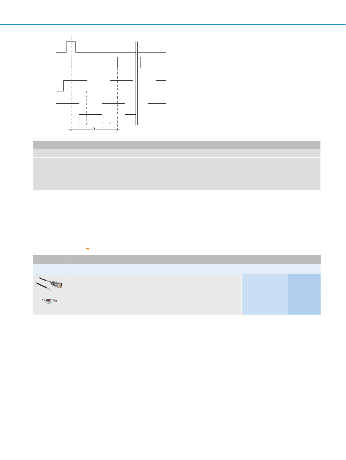
A + B
Time
At constant rotational speed with regard to the input shaft and rotation in clockwise direction.
By connecting the two signals A and B, an output signal arises whose period durations tx1 ... tx4 have varying lengths.
The differences are determined:
• by the pulse/pause ratio tolerance of the individual channels
• by the tolerance in the 90° phase shift between A and B
• by the frequency
The times tx1 ... tx4 ideally have to amount to 1/4 of the particular period duration T. The typical output frequency of the encoder is
Diagrams
CFS50-AEV12X03 | CFS50
MOTOR FEEDBACK SYSTEMS ROTARY INCREMENTAL WITH COMMUTATION
At constant speed, looking at the input shaft, and clockwise rotation
2020-08-22 08:21:24 | Product data sheet
Subject to change without notice
MOTOR FEEDBACK SYSTEMS | SICK 5
A
B
C
D
E
F
H
I
J
K
L
M
N
O
P
Q
R
S
T
Z
R
S
T
e
f g h i k
Polpairs Number of poles e, f, g, h, i, k
α
2 4 30° 180°
3 6 20° 120°
4 8 15° 90°
6 12 10° 60°
8 16 7.5° 45°
The angle information is related to a mechanical shaft rotation. Flank precision of the signals R, S, T ±1°.
CFS50-AEV12X03 | CFS50
MOTOR FEEDBACK SYSTEMS ROTARY INCREMENTAL WITH COMMUTATION
Recommended accessories
Other models and accessories www.sick.com/CFS50
Brief description Type Part no.
Plug connectors and cables
Head A: female connector, JST, 8-pin, straight
Head B: male connector, M23, 17-pin, straight
Cable: Incremental, unshielded, 1m
Head A: female connector, terminal box, 8-pin, straight
Head B: male connector, M23, 17-pin, straight
Cable: Incremental, unshielded, 1m
DSL-2317-G01MJB7 2071332
DSL-2317-G01MJC7 2071331
6 MOTOR FEEDBACK SYSTEMS | SICK Product data sheet | 2020-08-22 08:21:24
Subject to change without notice

Online data sheet
SICK AG | Waldkirch | Germany | www.sick.com
SICK AT A GLANCE
SICK is one of the leading manufacturers of intelligent sensors and sensor solutions for industrial applica-
tions. A unique range of products and services creates the perfect basis for controlling processes securely
and efciently, protecting individuals from accidents and preventing damage to the environment.
We have extensive experience in a wide range of industries and understand their processes and require-
ments. With intelligent sensors, we can deliver exactly what our customers need. In application centers in
Europe, Asia and North America, system solutions are tested and optimized in accordance with customer
specications. All this makes us a reliable supplier and development partner.
Comprehensive services complete our offering: SICK LifeTime Services provide support throughout the ma-
chine life cycle and ensure safety and productivity.
For us, that is “Sensor Intelligence.”
WORLDWIDE PRESENCE:
Contacts and other locations – www.sick.com
 Loading...