

Page 1

CFP CUBIC
Level sensor
OPERATING INSTRUCTIONS
en
Page 2

Product described
CFP Cubic
Manufacturer
SICK AG
Erwin-Sick-Str. 1
79183 Waldkirch
Germany
Legal notes
This work is protected by copyright. The associated rights are reserved by SICK AG.
Reproduction of this document or parts of this document is only permissible within
the limits of the legal provisions of copyright law.
Any modication, abridgment, or translation of this document is prohibited without
the express written permission of SICK AG.
The trademarks mentioned in this document are the property of their respective
owners.
© SICK AG. All rights reserved.
Original document
This document is an original document published by SICK AG.
2
OPERATING INSTRUCTIONS | CFP CUBIC 8021989 / 2017-10-20 | SICK AG
Subject to change without notice
Page 3

Content
1 About this document .......................................................................................6
1.1 Information on the operating instructions ...............................................................6
1.2 Scope .........................................................................................................................6
1.3 Explanation of symbols .............................................................................................6
1.4 Further information ...................................................................................................7
1.5 Customer service ......................................................................................................7
2 Safety information ...........................................................................................8
2.1 Intended use ..............................................................................................................8
2.2 Improper use .............................................................................................................8
2.3 Limitation of liability ..................................................................................................8
2.4 Modications and conversions .................................................................................8
2.5 Requirements for skilled persons and operating personnel ..................................9
2.6 Operational safety and specic hazards ..................................................................9
2.7 General safety notes .............................................................................................. 10
2.8 Repairs .................................................................................................................... 10
3 Product description ....................................................................................... 11
3.1 Product identication ............................................................................................. 11
3.1.1 Information on the housing .................................................................... 11
3.1.2 Type code ................................................................................................ 11
3.2 Product characteristics .......................................................................................... 12
3.2.1 Device view ............................................................................................. 12
3.2.2 Operating buttons ................................................................................... 12
3.3 Product features and functions ............................................................................. 12
3.3.1 Principle of operation ............................................................................. 12
3.3.2 Fields of application ............................................................................... 12
4 Transport and storage .................................................................................. 13
4.1 Transport ................................................................................................................. 13
4.2 Transport inspection .............................................................................................. 13
4.3 Storage .................................................................................................................... 13
5 Mounting......................................................................................................... 14
5.1 Installation conditions............................................................................................ 14
5.2 Installation in a container ...................................................................................... 14
6 Electrical installation .................................................................................... 15
6.1 Safety ...................................................................................................................... 15
6.1.1 Notes on the electrical installation ........................................................ 15
6.2 Electrical connection .............................................................................................. 16
6.2.1 Overview of the electrical connections ................................................. 16
6.2.2 Pin assignment, M12 plug connector, 5-pin
(depending on the variant) ..................................................................... 16
6.2.3 Pin assignment, M12 plug connector, 8-pin ......................................... 17
Subject to change without notice
OPERATING INSTRUCTIONS | CFP CUBIC8021989 / 2017-10-20 | SICK AG
3
Page 4

7 Commissioning .............................................................................................. 18
7.1 Quick commissioning (with factory settings) ........................................................ 18
7.2 Commissioning ....................................................................................................... 18
8 Operation ........................................................................................................ 20
8.1 Display and pushbuttons ....................................................................................... 20
8.1.1 Variants with two switching outputs ...................................................... 20
8.1.2 Variants with four switching outputs ..................................................... 20
8.1.3 IO-Link ..................................................................................................... 20
8.2 User and Exprt mode ............................................................................................. 20
8.2.1 User mode ............................................................................................... 20
8.2.2 Exprt mode .............................................................................................. 21
8.3 Conguring the switching outputs ......................................................................... 21
8.3.1 Switching hysteresis and window function ........................................... 21
8.3.2 Normally open with congurable hysteresis ......................................... 22
8.3.3 Normally closed with congurable hysteresis ....................................... 23
8.3.4 Normally open with window function..................................................... 24
8.3.5 Normally closed with window function .................................................. 25
8.3.6 Normally open with error signal ............................................................. 27
8.3.7 Switching output as input for processing external signals ................... 27
8.4 Conguration of analog outputs ............................................................................ 28
8.4.1 Automatic signal detection .................................................................... 28
8.4.2 Current output 4 to 20 mA ..................................................................... 29
8.4.3 Voltage output 0-10 V ............................................................................ 29
8.4.4 Behavior of outputs in the event of an error ......................................... 30
8.5 Advanced functions ................................................................................................ 30
8.5.1 Selecting display unit ............................................................................. 30
8.5.2 Setting an alternating display of measurands (DispA and DispB) ....... 30
8.5.3 Autocalibration ........................................................................................ 31
8.5.4 Performing empty adjustment ............................................................... 31
8.5.5 Locking the display without a password ............................................... 31
8.5.6 Locking the display with a password ..................................................... 32
8.5.7 Setting the medium adjustment ........................................................... 32
8.5.8 Filtering measured values ...................................................................... 32
8.5.9 Testing the conguration ........................................................................ 32
8.5.10 Evaluating signal quality ........................................................................ 34
8.5.11 Setting the offset .................................................................................... 35
8.5.12 Resetting the calibration ........................................................................ 36
9 Menu overview ............................................................................................... 37
9.1 User mode .............................................................................................................. 37
9.2 Exprt mode ............................................................................................................. 38
10 Overview of parameters ............................................................................... 41
4
OPERATING INSTRUCTIONS | CFP CUBIC 8021989 / 2017-10-20 | SICK AG
Subject to change without notice
Page 5

11 Troubleshooting ............................................................................................. 44
11.1 Error message on the display ................................................................................ 44
11.2 Operating the display ............................................................................................. 45
11.3 Outputs ................................................................................................................... 45
11.4 Error behavior ......................................................................................................... 45
12 Repair .............................................................................................................. 47
12.1 Maintenance ........................................................................................................... 47
12.2 Returns ................................................................................................................... 47
13 Disposal .......................................................................................................... 48
14 Technical data ................................................................................................ 49
14.1 Note for critical applications .................................................................................. 49
14.2 Features .................................................................................................................. 49
14.3 Performance ........................................................................................................... 49
14.4 Mechanics/materials ............................................................................................. 50
14.5 Reference conditions ............................................................................................. 50
14.6 Ambient conditions ................................................................................................ 50
14.7 Electrical connections ............................................................................................ 51
15 Dimensional drawings .................................................................................. 52
16 Factory setting ............................................................................................... 53
17 Accessories .................................................................................................... 54
Subject to change without notice
OPERATING INSTRUCTIONS | CFP CUBIC8021989 / 2017-10-20 | SICK AG
5
Page 6

1 ABOUT THIS DOCUMENT
1 About this document
1.1 Information on the operating instructions
These operating instructions provide important information on how to use sensors from
SICK AG.
Prerequisites for safe work are:
• Compliance with all safety notes and handling instructions supplied.
• Compliance with local work safety regulations and general safety regulations for
sensor applications.
The operating instructions are intended to be used by qualied personnel and electrical
specialists.
Note:
Read these operating instructions carefully before starting any work on the device,
in order to familiarize yourself with the device and its functions.
The instructions constitute an integral part of the product and are to be stored in the
immediate vicinity of the device so they remain accessible to staff at all times. Should
the device be passed on to a third party, these operating instructions should be handed
over with it.
These operating instructions do not provide information on operating the machine in
which the sensor is integrated. For information about this, refer to the operating instructions of the specic machine.
1.2 Scope
These operating instructions explain how to incorporate a sensor into a customer
system. Instructions are given in stages for all actions required.
These instructions apply to all available device variants of the sensor. For more detailed
information on identifying your device type, see “3.1.2 Type code”.
Available device variants are listed on the online product page:
b www.sick.com/CFP_Cubic
A number of device variants are used as examples for commissioning, based on the
default parameter settings for the relevant device.
1.3 Explanation of symbols
Warnings and important information in this document are labeled with symbols. The
warnings are introduced by signal words that indicate the extent of the danger. These
warnings must be observed at all times and care must be taken to avoid accidents,
personal injury, and material damage.
HAZARD
… indicates a situation of imminent danger, which will lead to a fatality or serious
injuries if not prevented.
WARNING
… indicates a potentially dangerous situation, which may lead to a fatality or serious
injuries if not prevented.
6
OPERATING INSTRUCTIONS | CFP CUBIC 8021989 / 2017-10-20 | SICK AG
Subject to change without notice
Page 7
CAUTION
… indicates a potentially dangerous situation, which may lead to minor/slight injuries if
not prevented.
IMPORTANT
… indicates a potentially harmful situation, which may lead to material damage if not
prevented.
HINT
… highlights useful tips and recommendations as well as information for efcient and
trouble-free operation.
1.4 Further information
HINT
All the documentation available for the sensor can be found on the online product page
at:
1ABOUT THIS DOCUMENT
www.sick.com
The following information is available for download from this page:
• Model-specic online data sheets for device variants, containing technical data,
dimensional drawings, and diagrams
• EU declaration of conformity for the product family
• Dimensional drawings and 3D CAD dimension models in various electronic formats
• These operating instructions, available in English and German, and in other languages
if necessary
• Other publications related to the sensors described here (e.g., IO-Link)
• Publications dealing with accessories
1.5 Customer service
If you require any technical information, our customer service department will be happy
to help. To nd your agency, see the nal page of this document.
HINT
Before calling, make a note of all sensor data such as type code, serial number, etc.,
to ensure faster processing.
Subject to change without notice
OPERATING INSTRUCTIONS | CFP CUBIC8021989 / 2017-10-20 | SICK AG
7
Page 8

2 SAFETY INFORMATION
2 Safety information
2.1 Intended use
The CFP Cubic is a level sensor based on a capacitive measurement principle. The level
is determined and the limit values are assessed by evaluating the capacitive elds.
The sensor is designed for both continuous level measurement and discontinuous level
measurement in nearly all liquids. Depending on the variant, temperature values can
also be processed continuously or as limit values.
The sensor fullls the requirements of EN 61326-2-3 for industrial environments.
2.2 Improper use
Any use outside of the stated areas, in particular use outside of the technical specications and the requirements for intended use, will be deemed to be incorrect use.
If the sensor is to be used under other conditions or in different environments, the
manufacturer’s service department may issue an operating license in consultation with
the customer and in exceptional cases.
2.3 Limitation of liability
Applicable standards and regulations, the latest technological developments, and
our many years of knowledge and experience have all been taken into account when
assembling the data and information contained in these operating instructions. The
manufacturer accepts no liability for damage caused by:
• Failing to observe the operating instructions
• Improper use
• Use by untrained personnel
• Unauthorized conversions
• Technical modications
• Use of unauthorized spare parts, consumables, and accessories
With special variants, where optional extras have been ordered, or owing to the latest
technical changes, the actual scope of delivery may vary from the features and illustra-
tions shown here.
2.4 Modications and conversions
IMPORTANT
Modications and conversions to the sensor and/or the installation may result in
unforeseeable dangers.
Interfering with or modifying the sensor or SICK software will invalidate any warranty
claims against SICK AG. This applies in particular to opening the housing, even as part
of mounting and electrical installation work.
Before making technical modications to or expanding the sensor, the prior written
approval of the manufacturer must be obtained.
8
OPERATING INSTRUCTIONS | CFP CUBIC 8021989 / 2017-10-20 | SICK AG
Subject to change without notice
Page 9

2.5 Requirements for skilled persons and operating personnel
WARNING
Risk of injury due to insufcient training.
Improper handling of the sensor may result in considerable personal injury and material
damage.
• All work must only ever be carried out by the stipulated persons.
The operating instructions state the following qualication requirements for the various
areas of work:
• Instructed personnel have been briefed by the operating entity about the tasks
assigned to them and about potential dangers arising from improper action.
• Skilled personnel have the specialist training, skills, and experience, as well as
knowledge of the relevant regulations, to be able to perform tasks assigned to
them and to detect and avoid any potential dangers independently.
• Electricians have the specialist training, skills, and experience, as well as knowledge
of the relevant standards and provisions to be able to carry out work on electrical
systems and to detect and avoid any potential dangers independently. In Germany,
electricians must meet the specications of the BGV A3 Work Safety Regulations
(e.g., Master Electrician). Other relevant regulations applicable in other countries
must be observed.
2SAFETY INFORMATION
The following qualications are required for various activities:
Tasks Qualication
Mounting, maintenance
Electrical installation,
device replacement
Commissioning,
conguration
Operation of the device for
the specic application
• Basic practical technical training
• Knowledge of the current safety regulations in the workplace
• Practical electrical training
• Knowledge of current electrical safety regulations
• Knowledge of device control and operation in the specic appli-
cation concerned (e.g., conveying line)
• Basic knowledge of the control system used
• Basic knowledge of the design and setup of the described
connections and interfaces
• Basic knowledge of data transmission
• Knowledge of device control and operation in the particular
application concerned (e.g., bottling plant)
• Knowledge of the software and hardware environment for the
particular application concerned (e.g., bottling plant)
2.6 Operational safety and specic hazards
Please observe the safety notes and the warnings listed here and in other chapters of
these operating instructions to reduce the possibility of risks to health and avoid dangerous situations.
Subject to change without notice
OPERATING INSTRUCTIONS | CFP CUBIC8021989 / 2017-10-20 | SICK AG
9
Page 10

2 SAFETY INFORMATION
2.7 General safety notes
• Read the operating instructions prior to commissioning.
• These operating instructions are valid for devices from rmware version 2.00.
• The CFP Cubic is not a safety component under the EU Machinery Directive.
• Observe national safety and work safety regulations.
• Wiring work and the opening and closing of electrical connections may only be
carried out when the power is switched off.
• The radiated power is far lower than that from telecommunication equipment.
According to current scientic research, the operation of this device can be classied as safe and non-hazardous.
2.8 Repairs
Repair work on the sensor may only be performed by qualied and authorized personnel
from SICK AG. Interference with or modications to the sensor on the part of the cus-
tomer will invalidate any warranty claims against SICK AG.
10
OPERATING INSTRUCTIONS | CFP CUBIC 8021989 / 2017-10-20 | SICK AG
Subject to change without notice
Page 11

3 Product description
3.1 Product identication
3.1.1 Information on the housing
Information for identication of the sensor and its electrical connection are printed on
the housing.
3.1.2 Type code
3PRODUCT DESCRIPTION
CFP
Cubic
1 2 3 4 5 6 7 8 9
Position Description
1 Product group
2 Probe length in mm
3 Certication
4 Probe design
5 Process connection
6 Application type
7 Housing
8 Electrical outputs
9 Additional options
0100 – X P Q N N C T
CFP Cubic: Capacitive level sensor CFP Cubic
0100:
100 mm
ascending in increments of 100 mm
...
1,000 mm
1,000:
X: Without certication
P: PP rod probe
X: Without process connection
A: G 3/4" A; PBT
B: 3/4" NPT; PBT
N: Oil and water applications
N: Plastic housing with display
A: 2 digital outputs
B: 2 digital outputs + 1 analog output
C: 4 digital outputs + 2 analog outputs
T: With temperature sensor
X: No additional options
Subject to change without notice
Not all variants of the type code can be combined!
OPERATING INSTRUCTIONS | CFP CUBIC8021989 / 2017-10-20 | SICK AG
11
Page 12
3 PRODUCT DESCRIPTION
3.2 Product characteristics
3.2.1 Device view
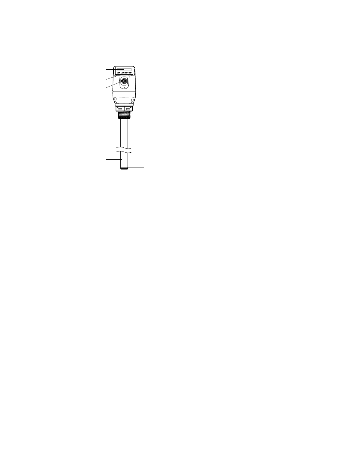
Fig. 1: CFP Cubic
1 Probe
2 Electrical connection
3 Operating buttons
4 Display
5 Temperature sensor (optional)
3.2.2 Operating buttons
The sensor is operated using the display and the operating buttons.
For a detailed description of the pushbuttons and their functions, see “8.1 Display and
pushbuttons”.
3.3 Product features and functions
3.3.1 Principle of operation
The CFP Cubic works according to the capacitive measurement principle. This means
that electrodes are integrated in the probe to span and measure a capacitive eld. The
medium touching the probe inuences the measured capacitance. Linear to the level,
this change in capacitance is then evaluated in the sensor and output as a corresponding level.
The sensor can output this level as a continuous measured value (analog output)
and can also derive two or four freely positionable switching points from it (switching
outputs). IO-Link communication is also available for the switching output Q1,
see “8.1.3 IO-Link”.
3.3.2 Fields of application
The MCiM technology developed by SICK enables convenient and reliable level measurement irrespective of the container material.
The CFP Cubic is suitable for both continuous level measurement and discontinuous
level measurement in nearly all liquids. Furthermore, temperature values can also be
processed continuously or as a limit value depending on the variant.
12
OPERATING INSTRUCTIONS | CFP CUBIC 8021989 / 2017-10-20 | SICK AG
Subject to change without notice
Page 13

4 Transport and storage
4.1 Transport
For your own safety, please read and observe the following notes:
IMPORTANT
Damage to the sensor due to improper transport.
• The device must be packaged for transport with protection against shock and damp.
• Recommendation: Use the original packaging as it provides the best protection.
• Transport should be performed by specialist staff only.
• The utmost care and attention is required at all times during unloading and transpor-
tation on company premises.
• Note the symbols on the packaging.
• Do not remove packaging until immediately before starting installation work.
4.2 Transport inspection
Immediately upon receipt in Goods-in, check the delivery for completeness and for any
damage that may have occurred in transit. In the case of transit damage that is visible
externally, proceed as follows:
4TRANSPORT AND STORAGE
4.3 Storage
• Do not accept the delivery or only do so conditionally.
• Note the scope of damage on the transport documents or on the transport company's delivery note.
• File a complaint.
Note:
Complaints regarding defects should be led as soon as these are detected. Damage
claims are only valid before the applicable complaint deadlines.
Store the device under the following conditions:
• Recommendation: Use the original packaging.
• Do not store outdoors.
• Store in a dry area that is protected from dust.
• Do not store in an airtight container: this is so that any residual moisture present
can escape.
• Do not expose to any aggressive substances.
• Protect from sunlight.
• Avoid mechanical shocks.
Subject to change without notice
• Storage temperature: see “14 Technical data”.
• Relative humidity: see “14 Technical data”.
• For storage periods of longer than 3 months, check the general condition of all
components and packaging on a regular basis.
OPERATING INSTRUCTIONS | CFP CUBIC8021989 / 2017-10-20 | SICK AG
13
Page 14
5 MOUNTING
5 Mounting
5.1 Installation conditions
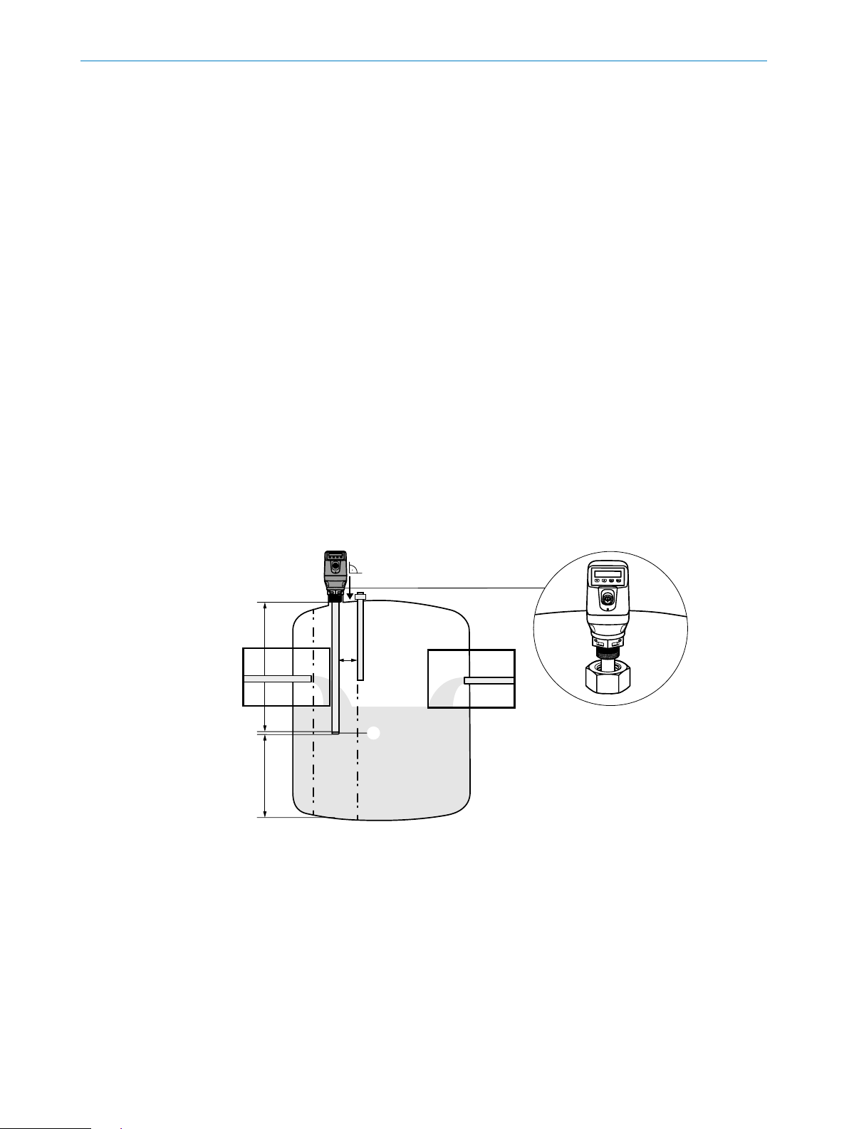
The CFP Cubic level sensor is mounted vertically from above into the container.
The sensor features a G 3/4 A, 3/4" NPT threaded connection or Easy Clamp bracket
(clamping bracket for innite adjustment of the required length).
A minimum connecting piece diameter in accordance with the following graphic must
be observed. The CFP Cubic is to be installed in such a way that, after it has been
mounted, there is a sufcient distance between it and other tank components (e.g.,
supply pipes, other measuring devices) as well as the sides and bottom of the con-
tainer.
These minimum distances are also specied in the following graphic. Observe a minimum distance of 30 mm to the container sides and to the tank components.
When operating the sensor, ensure that the ambient temperature is not above or below
the limits. Insulating the sensor housing is not permitted for tanks with hot media.
When positioning the device, ensure that the sensor is not directly exposed to the lling
ow and that at least 10 mm of the probe is covered by the medium to be measured on
all sides.
The sensor housing can be rotated 360°, allowing for the cable outlet to be positioned
freely. If the process temperature drops below 0 °C during operation, the probe must
not be subjected to transverse loads.
5.2 Installation in a container
1
X
4
Fig. 2: CFP Cubic in the container
1 100 ... 1,000 mm measuring range
2 min. 30 mm
3 10 mm inactive area at probe end
4 min. 10 mm
2
G 3/4" A
3/4" NPT
3
14
OPERATING INSTRUCTIONS | CFP CUBIC 8021989 / 2017-10-20 | SICK AG
Subject to change without notice
Page 15

6 Electrical installation
6.1 Safety
6.1.1 Notes on the electrical installation
IMPORTANT
Equipment damage due to incorrect supply voltage!
An incorrect supply voltage may result in damage to the equipment.
• Only operate the device using a protected low voltage and safe electrical insulation
as per protection class III.
IMPORTANT
Equipment damage or unpredictable operation due to working with live parts.
Working with live parts may result in unpredictable operation.
• Only carry out wiring work when the power is off.
• Only connect and disconnect electrical connections when the power is off.
6ELECTRICAL INSTALLATION
• The electrical installation must only be performed by electrically qualied person-
nel.
• Standard safety requirements must be met when working on electrical systems.
• Only switch on the supply voltage for the device when the connection tasks have
been completed and the wiring has been thoroughly checked.
• When using extension cables with open ends, ensure that bare wire ends do not
come into contact with each other (risk of short-circuit when supply voltage is
switched on!). Wires must be appropriately insulated from each other.
• Wire cross-sections in the supply cable from the user’s power system must be
designed in accordance with the applicable standards. In Germany, observe the
following standards:
DIN VDE 0100 (Part 430) and DIN VDE 0298 (Part 4) or DIN VDE 0891 (Part 1).
• Circuits connected to the device must be designed as SELV circuits
(SELV = Safety Extra Low Voltage).
• Protect the device with a separate fuse at the start of the supply circuit.
Notes on layout of data cables:
• To avoid interference, e.g., from switching power supplies, motors, clocked drives,
and contactors, always use suitable EMC cables and layouts.
• Do not lay cables over long distances in parallel with voltage supply cables and
motor cables in cable channels.
Subject to change without notice
The IP 67 enclosure rating for the device is only achieved under the following conditions:
• The cable on the M12 connection has been screwed on.
If this is not done, the device does not fulll any specied IP enclosure rating!
OPERATING INSTRUCTIONS | CFP CUBIC8021989 / 2017-10-20 | SICK AG
15
Page 16
6 ELECTRICAL INSTALLATION
12
4 3
5
6.2 Electrical connection
6.2.1 Overview of the electrical connections
The sensor is connected using a pre-assembled female cable connector with 1 x M12
plug connector (5-pin or 8-pin). With the power switched off, plug the female cable connector into the sensor and screw it tight.
Connect the cable according to its function. After the supply voltage has been applied,
the sensor carries out a self-test. Once installed, the sensor is ready for operation on
completion of the self-test (< 5 s) and the display shows the current measured value.
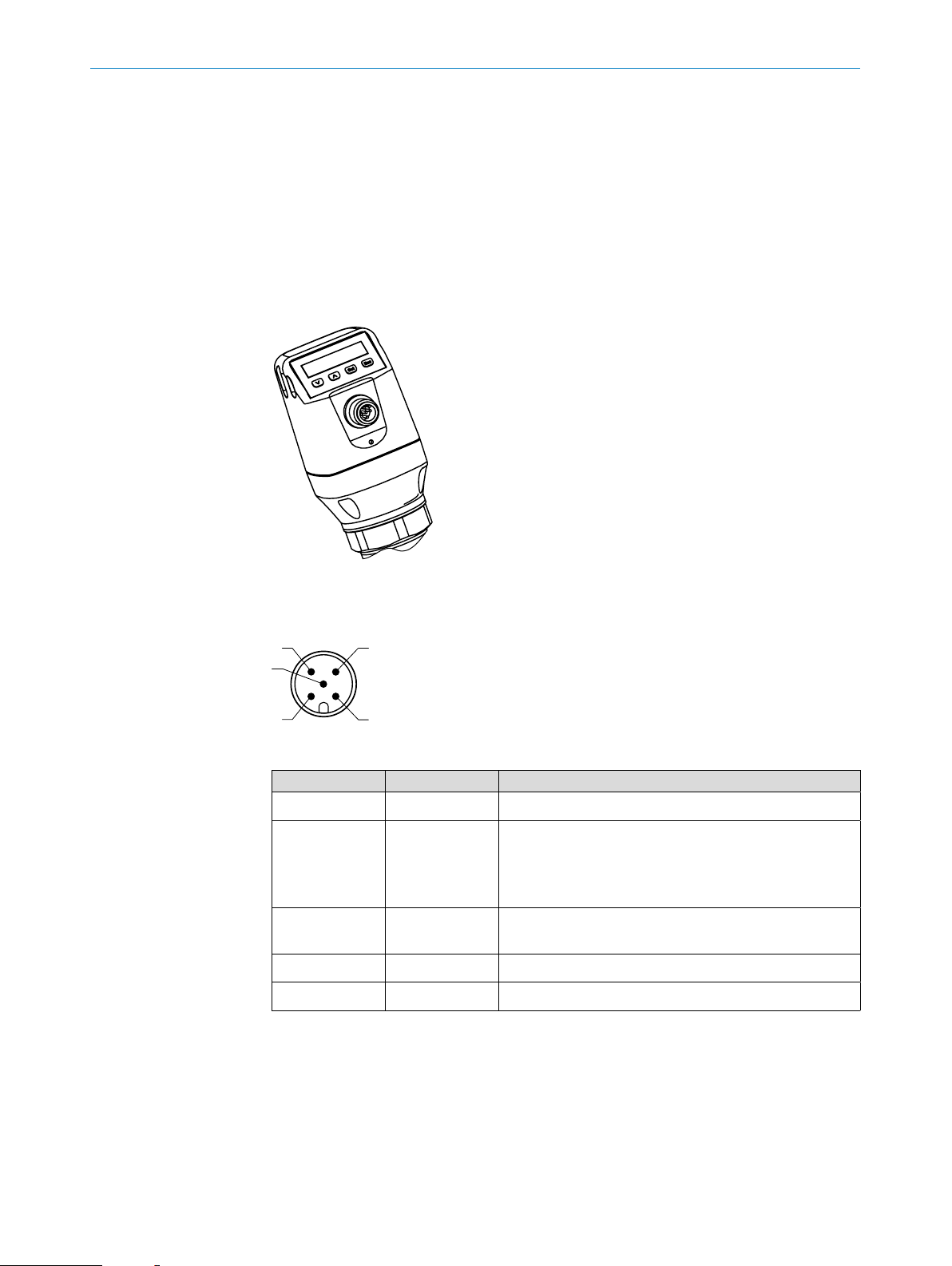
Fig. 3: CFP Cubic device view
6.2.2 Pin assignment, M12 plug connector, 5-pin (depending on the variant)
Fig. 4: M12 x 1 plug connector, 5-pin
Pin Identication Description
1 L+ Supply voltage
2 Q
3 M Ground, reference potential for
4 C/Q
5 Q
A
1
2
Current output 4 ... 20 mA
Or
Voltage output 0 ... 10 V
Variant-dependent
current/voltage output
Switching output 1, PNP / NPN / DRV (push-pull) / IO-Link
Switching output 2, PNP / NPN / DRV (push-pull)
16
OPERATING INSTRUCTIONS | CFP CUBIC 8021989 / 2017-10-20 | SICK AG
Subject to change without notice
Page 17

6.2.3 Pin assignment, M12 plug connector, 8-pin
5
8
6ELECTRICAL INSTALLATION
2
3
4
1
7
6
Fig. 5: M12 x 1 plug connector, 8-pin
Pin Identication Description
1 L+ Supply voltage
2 Q
2
Switching output 2, PNP / NPN / DRV (push-pull)
3 M Ground, reference potential for current / voltage output
4 C/ Q
5 Q
6 Q
7 Q
8 Q
3
4
A
B
1
Switching output 1, PNP / NPN / DRV (push-pull) / IO-Link
Switching output 3, PNP / NPN / DRV (push-pull)
Switching output 4, PNP / NPN / DRV (push-pull)
Analog current / voltage output
Analog current / voltage output
The wire colors for 8-pin cables are not uniform. Always note the pin assignment of the
sensor.
Subject to change without notice
OPERATING INSTRUCTIONS | CFP CUBIC8021989 / 2017-10-20 | SICK AG
17
Page 18

7 COMMISSIONING
7 Commissioning
7.1 Quick commissioning (with factory settings)
General requirements
− Installation according to reference conditions (safety distances, etc.)
− Can only be used if installed using G3/4" A or 3/4
Quick commissioning
1. Mount the sensor as appropriate to the installation conditions, see “5 Mounting”.
2. Adapt the level so that approximately 50% of the probe is covered with the measuring medium.
3. Automatically adjust the medium.
• Adjust using AUTCAL.
• The successful AUTCAL function is conrmed with !CALOK.
4. Congure outputs, see “8.3 Conguring the switching outputs”.
Note:
The following parameters are automatically adjusted while executing the AUTCAL function:
• The EXPRT / MEAS / TRSHLD parameter is adjusted.
• The EXPRT / MEAS / ADAPT = 60 s parameter is adjusted.
Note:
If the AUTCAL function was conrmed with !FAILD, relaunch commissioning.
" NPT process connection
This menu can be accessed via EXPRT and USER.
In the event of problems during commissioning, see “11 Troubleshooting”.
7.2 Commissioning
Advanced commissioning must always be performed if the required measurement
performance is not achieved after quick commissioning. This may be the case if, for
example, media with very low DC values (e.g., silicone oils) are to be measured.
Advanced commissioning must also be performed during assembly with an Easy Clamp
bracket.
General requirements
− Installation according to reference conditions (safety distances, etc.)
− Installation using G3/4" A or 3/4
− Installation using Easy Clamp
18
OPERATING INSTRUCTIONS | CFP CUBIC 8021989 / 2017-10-20 | SICK AG
" NPT process connection
Subject to change without notice
Page 19

Commissioning
1. Mount the sensor as appropriate to the installation conditions, see “5 Mounting”.
2. The level must be at least 10 mm below the end of the probe.
3. Perform empty adjustment.
4. Adapt the level in the container until approx. 50% of the probe is covered with the
5. Automatically adjust the medium.
6. Analyze the signal quality, see “8.5.10 Evaluating signal quality”.
7. Congure the lter, see “8.5.8 Filtering measured values”.
7COMMISSIONING
This menu can be accessed via EXPRT and USER.
• Perform the adjustment using CALEMP.
• The successful empty adjustment is conrmed with !CALOK.
measuring medium.
• Adjust using AUTCAL.
• The successful AUTCAL function is conrmed with !CALOK.
Perform the following steps if the signal quality is not sufcient:
• Reduce the value in the MEAS / TRSHLD menu.
8. Congure outputs, see “8.3 Conguring the switching outputs”.
Note:
If the AUTCAL function was conrmed with !FAILD, relaunch commissioning.
Note:
The following parameters are automatically adjusted while executing the AUTCAL function:
• The EXPRT / MEAS / TRSHLD parameter is adjusted.
• The EXPRT / MEAS / ADAPT = 60 s parameter is adjusted.
Note:
If the CalEmp function was conrmed with !FAILD, relaunch commissioning.
Note:
If a quick adjustment to a new medium is required, the EXPRT / MEAS / ADAPT parameter has to be reduced.
In the event of problems during commissioning, see “11 Troubleshooting”.
Subject to change without notice
OPERATING INSTRUCTIONS | CFP CUBIC8021989 / 2017-10-20 | SICK AG
19
Page 20

8 OPERATION
8 Operation
8.1 Display and pushbuttons
All lengths specied in the menu refer to the end of the probe and/or with a congured
offset (see “8.5.11 Setting the offset”) to the tank bottom.
8.1.1 Variants with two switching outputs
Q1 Q2
1000 mm
Arrow pushbuttons: For navigating in the menu and changing values
Set pushbutton: For saving and conrming
Esc pushbutton: To exit the operating menu one step at a time
Note:
The status of the switching outputs is indicated in millimeters by the bars above the
mm unit symbol. This display is not available when inches are selected as the unit.
8.1.2 Variants with four switching outputs
Q1/2/3/4
1000 mm
Arrow pushbuttons: For navigating in the menu and changing values
Set pushbutton: For saving and conrming
Esc pushbutton: To exit the operating menu one step at a time
39.4 in
39.4 in
8.1.3 IO-Link
For operation via IO-Link 1.1 with data storage, the following les can be downloaded
from www.sick.com:
− IODD le
− Description of the available telegram parameters
8.2 User and Exprt mode
The two menu structures User mode and Exprt mode are available for users. The Exprt
mode contains additional functions for advanced settings.
You can access the menu by pressing the Set pushbutton for at least three seconds.
8.2.1 User mode
The User mode makes it easy to commission many standard applications. The number
of parameters that can be set on the display is reduced.
20
OPERATING INSTRUCTIONS | CFP CUBIC 8021989 / 2017-10-20 | SICK AG
Subject to change without notice
Page 21

8.2.2 Exprt mode
8OPERATION
The Exprt mode offers the full functionality of the display.
Advanced functions are available for:
− Switching outputs
• Output: Process variable, hysteresis/window, polarity, simulation, electrical
property (NPN / PNP / DRV (push-pull))
• Using the switching output as input for initiating actions (minLvl, maxLvl, etc.)
− Analog outputs
• Switching the process variable, 4–20 mA/0–10 V, error signal, simulation
− Conguration
• Display, units, offset, lock
− Measurement
• Detailed signal quality, lter, TrsHld
Note:
Exprt mode is automatically activated when IO-Link is used.
8.3 Conguring the switching outputs
8.3.1 Switching hysteresis and window function
2 or 4 outputs depending on variant
Level
SP
RP
high
low
high
low
HNO
HNC
If the level is uctuating around the set
value (e.g., ripple movement during ll
ing), the hysteresis keeps the switching
t
status of the outputs stable. When the
-
level is increasing, the output switches
when the respective switching point
(SP) is reached; if the level sinks again,
the output switches back only after the
reset switching point (RP) has been
reached.
Subject to change without notice
OPERATING INSTRUCTIONS | CFP CUBIC8021989 / 2017-10-20 | SICK AG
21
Page 22

8 OPERATION
2 or 4 outputs depending on variant
Level
FH
FL
high
low
high
low
8.3.2 Normally open with congurable hysteresis
Applications
− Dry run protection
− Empty signal
FNC
FNO
The window function enables monitor-
ing of a dened range. If the level is
between window high (FH) and window
low (FL), the output will be active
(normally open) or inactive (normally
closed).
t
The error status of the measuring
device reects the cable break monitoring. During an error status, the measur-
ing device switches to a safe state; i.e.
the switching outputs become inactive.
As far as the downstream signal evalu-
ation is concerned, this corresponds to
a cable break.
Conguration
Congure the Qx switching output as normally open (using Q1 as an example).
Note:
The switching output designation (Q1 in the example here) changes according to the
selected process variable to be output.
The following conguration is only possible if the value is set to LEVEL or TEMPER under
PROC1.
1. Log in to Exprt mode, see “8.2.2 Exprt mode”.
2. Congure the switching output as output in the Q1-### / MODE1 / OUTPUT menu.
3. Congure the process variable to be output.
• Set the value to LEVEL or TEMPER in the Q1-### / PROC1 menu.
4. Set the Hysteresis mode in the Q1-### / OUT1 / HYST. menu.
• Set the parameter to NO in the Q1-### / POL1 menu.
5. Set the switching point.
• Set the value in the Q1-### / SP1 menu to level in mm (e.g., 500 mm).
6. Set the reset point.
• Set the value in the Q1-### / RP1 menu to level in mm (e.g., 450 mm).
22
7. Select the electrical property (NPN/PNP/DRV [push/pull]).
Select the parameter in the Q1-### / TYP1 menu.
The following rules apply:
OPERATING INSTRUCTIONS | CFP CUBIC 8021989 / 2017-10-20 | SICK AG
Subject to change without notice
Page 23

• PNP = Switching output in PNP circuit
t
disable
• NPN = Switching output in NPN circuit
• DRV = Switching output in push/pull function
Switching output behavior
Level
SP
RP
8OPERATION
active
d
Switching output PNP NPN DRV Error status
Normally open/HNO
1)
Pulldown only
2)
Pullup only
active U
disabled 0 V
8.3.3 Normally closed with congurable hysteresis
Applications
− Overll protection
− Full signal
Conguration
Congure the Qx switching output as normally closed (using Q1 as an example).
Note:
Error signal
0 V Uv (PNP switched)
v
1)
Uv 2) 0 V (NPN switched)
disabled
Subject to change without notice
The switching output designation (Q1 in the example here) changes according to the
selected process variable to be output.
1. Log in to Exprt mode, see “8.2.2 Exprt mode”.
2. Set the Output mode in the Q1-### / MODE1 / OUTPUT menu.
3. Congure the process variable to be output.
• Set the parameter to the required value in the Q1-### / PROC1 menu.
4. Set the Hysteresis mode in the Q1-### / OUT1 / HYST. menu.
5. Congure the switching output.
• Set the parameter to NC in the Q1-### / POL1 menu.
OPERATING INSTRUCTIONS | CFP CUBIC8021989 / 2017-10-20 | SICK AG
23
Page 24

8 OPERATION
Switching output behavior
6. Set the switching point.
• Set the value in the Q1-### / SP1 menu to level in mm (e.g., 500 mm).
7. Set the reset point.
• Set the value in the Q1-### / RP1 menu to level in mm (e.g., 450 mm).
8. Select the electrical property (NPN/PNP/DRV [push/pull]).
Select the parameter in theQ1-LVL / TYP1 menu.
The following rules apply:
• PNP = Switching output in PNP circuit
• NPN = Switching output in NPN circuit
• DRV = Switching output in push/pull function
Level
SP
RP
t
Error signal
active
disabled
Switching output PNP NPN DRV Error status
Normally closed/
HNC
1)
Pulldown only
2)
Pullup only
active U
disabled 0 V
0 V Uv (PNP switched) disabled
v
2)
1)
U
0 V (NPN switched)
v
8.3.4 Normally open with window function
Application
Thecritical lling level for the application is within the FHx and FLx window thresholds.
Conguration
Congure the Qx switching output as normally open (using Q1 as an example).
24
Note:
The switching output designation (Q1 in the example here) changes according to the
selected process variable to be output.
1. Log in to Exprt mode, see “8.2.2 Exprt mode”.
OPERATING INSTRUCTIONS | CFP CUBIC 8021989 / 2017-10-20 | SICK AG
Subject to change without notice
Page 25

2. Set the Output mode in the Q1-### / MODE1 / OUTPUT menu.
3. Congure the process variable to be output.
• Set the parameter to the required value in the Q1-### / PROC1 menu.
4. Set the Window mode in the Q1-### / OUT1 / WINDOW menu.
5. Congure the switching output as normally open.
• Set the parameter to NO in the Q1-### / POL1 menu.
6. Set the switching point.
• Set the value in the Q1-### / FH1 menu to level in mm (e.g., 500 mm).
7. Set the reset point.
• Set the value in the Q1-### / FL1 menu to level in mm (e.g., 400 mm).
8. Select the electrical property (NPN/PNP/DRV [push/pull]).
Select the parameter in the Q1-### / TYP1 menu.
The following rules apply:
• PNP = Switching output in PNP circuit
• NPN = Switching output in NPN circuit
8OPERATION
• DRV = Switching output in push/pull function
Switching output behavior
Level
FH
FL
active
disabled
Switching output PNP NPN DRV Error status
Normally open/FNO
1)
Pulldown only
2)
Pullup only
Error signal
active U
v
disabled 0 V
t
0 V Uv (PNP switched)
1)
2)
Uv
0 V (NPN switched)
disabled
8.3.5 Normally closed with window function
Application
The critical lling level for the application is outside the FHx and FLx window thresholds.
Subject to change without notice
OPERATING INSTRUCTIONS | CFP CUBIC8021989 / 2017-10-20 | SICK AG
25
Page 26

8 OPERATION
Conguration
Congure the Qx switching output as normally closed (using Q1 as an example).
Note:
The switching output designation (Q1 in the example here) changes according to the
selected process variable to be output.
1. Log in to Exprt mode, see “8.2.2 Exprt mode”.
2. Set the Output mode in the Q1-### / MODE1 / OUTPUT menu.
3. Congure the process variable to be output.
• Set the parameter to the required value in the Q1-### / PROC1 menu.
4. Set the Window mode in the Q1-### / OUT1 / WINDOW menu.
5. Congure the Q1 switching output as normally closed.
• Set the parameter to NC in the Q1-### / POL1 menu.
6. Set the switching point.
• Set the value in the Q1-### / FH1 menu to level in mm (e.g., 500 mm).
7. Set the reset point.
• Set the value in the Q1-### / FL1 menu to level in mm (e.g., 400 mm).
8. Select the electrical property (NPN/PNP/DRV [push/pull]).
Select the parameter in the Q1-### / TYP1 menu.
The following rules apply:
• PNP = Switching output in PNP circuit
• NPN = Switching output in NPN circuit
• Drv = Switching output in push/pull function
Switching output behavior
Level
FH
FL
active
disabled
Error signal
t
26
OPERATING INSTRUCTIONS | CFP CUBIC 8021989 / 2017-10-20 | SICK AG
Subject to change without notice
Page 27

Switching output PNP NPN DRV Error status
8OPERATION
Normally closed/FNC
1)
Pulldown only
2)
Pullup only
8.3.6 Normally open with error signal
Application
If there is an error message on the CFP Cubic, this can be output using a switching
output.
Conguration
Congure the Qx switching output as normally open for error signals (using Q1 as an
example).
Note:
The switching output designation (Q1 in the example here) changes according to the
selected process variable to be output: Q1-LVL or Q1-TEMP is now Q1-STA.
1. Log in to Exprt mode, see “8.2.2 Exprt mode”.
active U
disabled 0 V
v
0 V Uv (PNP switched)
1)
2)
Uv
0 V (NPN switched)
disabled
2. Congure Q1 as output.
• Set the parameter to OUTPUT in the Q1-### / MODE1 menu.
3. Congure the process variable to be output.
• Set the parameter to STATUS in the Q1-### / PROC1 menu.
4. Set the status to be output in the Q1-STA / STAT1 menu.
• Set the parameter to FAILURE in the Q1-STA / STAT1 menu.
5. Congure the Q1 switching output as normally open.
• Set the parameter to NO (normally open) in the Q1-STA / POL1 menu.
6. Select the electrical property (NPN/PNP/DRV [push/pull]).
Select the parameter in the Q1-TYP1 menu.
The following rules apply:
• PNP = Switching output in PNP circuit
• NPN = Switching output in NPN circuit
• DRV = Switching output in push/pull function
8.3.7 Switching output as input for processing external signals
Application
Switching outputs can also be used as inputs for the CFP Cubic. This enables you to
integrate external signals (e.g., from a tuning fork). In this way, the CFP Cubic can be
used as a mini PLC and reduces the number of cables to the PLC.
Subject to change without notice
OPERATING INSTRUCTIONS | CFP CUBIC8021989 / 2017-10-20 | SICK AG
27
Page 28

8 OPERATION
Conguration
Congure the Qx switching output as input (using Q1 as a redundant overll protection
example).
Note:
The switching output designation (Q1 in the example here) changes according to the
selected process variable to be output: Q1-LVL or Q1-TEMP is now Q1-INP.
1. Log in to Exprt mode, see “8.2.2 Exprt mode”.
2. Congure Q1 as input.
• Set the parameter to INPUT in the Q1-### / MODE1 menu.
3. Congure the action to be performed when the signal is present.
• Set the parameter to MAXLVL in the Q1-INP / ACTIO1 menu (if the external
signal is present, the CFP Cubic outputs the MAXLVL status).
4. Congure the form of the external signal.
• Set the parameter to NO (normally open) in the Q1-INP / POL1 menu.
8.4 Conguration of analog outputs
8.4.1 Automatic signal detection
The CFP Cubic can automatically detect if a 4–20 mA or 0–10 V signal is required
using the connected output load.
The following rules apply:
• 4 mA to 20 mA if load < 500 ohms at U
• 4 mA to 20 mA if load < 350 ohms at U
• 0 V to 10 V if load > 750 ohms at U
Conguration
Note:
The analog output designation (QA in the example here) changes according to the
selected process variable to be output.
1. Perform automatic signal detection.
• Set the parameter to AUTO in the QA-### menu.
Note:
Automatic signal detection is only active when the device is switched on for the rst
time. After this, the function can be activated again with AUTO in the QA-### menu.
V
V
≥ 14 V
V
> 15 V
> 12 V
28
OPERATING INSTRUCTIONS | CFP CUBIC 8021989 / 2017-10-20 | SICK AG
Subject to change without notice
Page 29

8.4.2 Current output 4 to 20 mA
Conguration
Note:
The analog output designation (QA in the example here) changes according to the
selected process variable to be output.
1. Log in to Exprt mode, see “8.2.2 Exprt mode”.
2. Dene the output as temperature or level (temperature sensor depends on variant).
• Set the parameter to TEMPER or LEVELin the QA-### / QAPROC menu.
3. Set the upper limit value for the level or temperature at which 20 mA is output.
• Set the parameter in the QA-### / QAHIGH menu to level in mm or tempera-
ture in °C (e.g., 500 mm).
4. Set the lower limit value for the level or temperature at which 4 mA is output.
• Set the parameter in the QA-### / QALOW menu to level in mm or tempera-
ture in °C (e.g., 10 mm).
8OPERATION
5. Invert the signal.
The analog signal can be inverted in the QAPOL menu.
Set the parameter to INVERT in the QA-### / QAPOL menu.
• Normal = Analog output signal as congured
• Invert = Analog output signal is inverted; QaHigh 4 mA and
6. Select electrical signal.
• Set the parameter in the QA-### / QATYP menu to 4 to 20 mA.
8.4.3 Voltage output 0-10 V
Conguration
Note:
The analog output designation (QA in the example here) changes according to the
selected process variable to be output.
1. Log in to Exprt mode, see “8.2.2 Exprt mode”.
2. Dene the output as temperature or level (temperature sensor depends on variant).
3. Set upper limit value (10 V).
• Set the parameter in the QA-### / QAHIGH menu to level in mm or tempera-
QaLow 20 mA
ture in °C (e.g., 500 mm).
Subject to change without notice
4. Set lower limit value (0 V).
• Set the parameter in the QA-### / QALOW menu to level in mm or tempera-
ture in °C (e.g., 10 mm).
5. Invert the signal.
The analog signal can be inverted in the QAPOL menu.
Set the parameter to INVERT in the QA-### / QAPOL menu.
• Normal = Analog output signal as congured
OPERATING INSTRUCTIONS | CFP CUBIC8021989 / 2017-10-20 | SICK AG
29
Page 30

8 OPERATION
• Invert = Analog output signal is inverted; QaHigh 0 V and QaLow 10 V
6. Select electrical signal.
Set the parameter in the QA-### / QATYP menu to 0–10 V.
8.4.4 Behavior of outputs in the event of an error
Conguration
Note:
The analog output designation (QA in the example here) changes according to the selected process variable to be output.
This function is only available if 4 to 20 mA is selected under QA-TYP.
1. Log in to Exprt mode, see “8.2.2 Exprt mode”.
2. Select electrical signal.
• Select the parameter in the QA-### / QA-TYP menu and set the value to 4 to
20 mA.
3. Dene the signal in the event of an error.
• Select the parameter in the QA-### / QA-FAIL menu and set to the required
value.
8.5 Advanced functions
8.5.1 Selecting display unit
The following units can be selected for the measured values:
− UnitLv: mm, inch
− UnitTm: °C, °F
Conguration
1. Log in to Exprt mode, see “8.2.2 Exprt mode”.
2. Set the unit for level.
• Set the unit in the CONFIG / UNITLV menu (mm/inch).
Or
1. Log in to Exprt mode, see “8.2.2 Exprt mode”.
2. Set the unit for temperature.
• Set the unit in the CONFIG / UNITTM menu (°C/°F).
8.5.2 Setting an alternating display of measurands (DispA and DispB)
Up to two measured values can be displayed alternately.
30
Function Description
Level Level in mm/inch
Level % Level in %
1)
Tem p
1)
QaSign
OPERATING INSTRUCTIONS | CFP CUBIC 8021989 / 2017-10-20 | SICK AG
Temperature in °C/°F
Qa analog output signal in mA/mV
Subject to change without notice
Page 31

1)
Conguration
1. Log in to Exprt mode, see “8.2.2 Exprt mode”.
2. Set the unit in the CONFIG / DISPA or DISPB menu.
8.5.3 Autocalibration
Autocalibration automatically determines the ideal setting for the TRSHLD (EXPRT /
MEAS / TRSHLD) and ADAPT (EXPRT / MEAS / ADAPT) parameters. The container must
be lled to 50% during calibration.
Autocalibration should always be performed in the following situations:
Function Description
1)
QbSign
QxSign Qx switching output status
variant-dependent
Qb analog output signal in mA/mV
− Commissioning has been carried out
− There has been a change in medium
8OPERATION
− The sensor's measurement performance is declining
Conguration
1. Log in to Exprt mode, see “8.2.2 Exprt mode”.
2. Perform autocalibration using AUTCAL.
• Conrm LEVEL AT 50%? using Set.
• The successful AUTCAL function is conrmed with !CALOK.
8.5.4 Performing empty adjustment
An empty adjustment must be performed if, for example, the signal quality is not sufcient or the sensor was mounted with an Easy Clamp bracket.
An empty adjustment is also performed during advanced commissioning,
see “7.2 Commissioning” on page 18.
Conguration
1. Log in to Exprt mode, see “8.2.2 Exprt mode”.
2. Perform the adjustment using MEAS / CALEMP.
• The successful empty adjustment is conrmed with !CALOK.
8.5.5 Locking the display without a password
Local operation on the sensor is immediately locked when the Local User Interface Lock
is activated via IO-Link. The Local User Interface Lock can only be activated via IO-Link.
Subject to change without notice
The !LOCKD message is displayed if you try to open the menu.
The display lock can be unlocked with the following steps:
− Via IO-Link by resetting the Local User Interface Lock
− Via the display by pressing the Set pushbutton for at least 10 seconds
OPERATING INSTRUCTIONS | CFP CUBIC8021989 / 2017-10-20 | SICK AG
31
Page 32

8 OPERATION
8.5.6 Locking the display with a password
1. Log in to Exprt mode, see “8.2.2 Exprt mode”.
2. Activate or deactivate the display lock using CONFIG / LOCK.
If the display lock is activated:
− The display is locked after a timeout of 5 minutes has elapsed
− The display is unlocked temporarily by entering the password 000237
Note:
When the display is locked, only the congured measured value display can be seen.
8.5.7 Setting the medium adjustment
This setting is used to congure the speed of the medium adjustment. The medium
adjustment allows the sensor to adapt to changing measuring media. The slower this
adjustment occurs, the more stable the measurement.
Note:
The value is automatically set to 60 s when AUTCAL is performed.
Conguration
1. Log in to Exprt mode, see “8.2.2 Exprt mode”.
2. Set the parameter in the MEAS / ADAPT menu.
The possible values are 60 s, 30 s, 10 s, 5 s, 1 s.
If the medium remains the same, a value of 60 s is recommended.
8.5.8 Filtering measured values
Activating ltering
The lter supports the smoothing of the measured value; e.g., in the case of ripples on
level surfaces. For fast level changes, the average of the measured values over x sec-
onds is indicated.
1. Log in to Exprt mode, see “8.2.2 Exprt mode”.
2. Set the parameter in the MEAS / FILTER menu.
The possible values are Off, 500 ms, 1 s, 2 s, 5 s, 10 s.
8.5.9 Testing the conguration
32
Testing outputs
Switching and analog outputs can be simulated. This allows for the wiring and signal
values on the connected systems, such as a PLC, to be checked.
OPERATING INSTRUCTIONS | CFP CUBIC 8021989 / 2017-10-20 | SICK AG
Subject to change without notice
Page 33

Conguration
Activating the Qx switching output
Note:
The switching output designation (Q1 in the example here) changes according to the
selected process variable to be output.
1. Log in to Exprt mode, see “8.2.2 Exprt mode”.
2. Activate the Q1 switching output
• Set the parameter to ON in the Q1-### / SIMQ1 menu.
Further options:
− Off = switching output off
− Norm = switching output in measuring operation
− On = switching output is active
Note:
8OPERATION
The simulation is automatically deactivated if the supply voltage is interrupted.
Activate the QA analog output
The sensor's analog outputs can be activated for simulation; for example, to check the
settings of a PLC.
Note:
The analog output designation (QA in the example here) changes according to the selected process variable to be output.
Conguration (using current output for level as an example)
1. Log in to Exprt mode, see “8.2.2 Exprt mode”.
2. Dene the level setting.
• Set the parameter to LEVEL in the QA-### / QAPROC menu.
3. Dene the current output.
• Set the parameter in the QA-### / QATYP menu to 4 to 20 mA.
4. Activate the simulation.
Simulating the level
Subject to change without notice
• Set the parameter in the QA-### / SIMQA menu to a value between 3.5 mA
and 21.5 mA.
A simulated level can be set to test the completed conguration in the sensor.
All parameters and outputs are then set according to the simulated level.
OPERATING INSTRUCTIONS | CFP CUBIC8021989 / 2017-10-20 | SICK AG
33
Page 34

8 OPERATION
Conguration
Parameter selection
1. Log in to Exprt mode, see “8.2.2 Exprt mode”.
2. Set the parameter to the desired ll level as a % in the CONFIG / SIMLEV menu.
3. Activate the simulation.
• Set the parameter to the required value in the QA-### / SIMQA menu.
Note:
The level simulation refers to the probe length and/or container level (probe length +
offset) if an offset is congured.
The simulation is only active when there are no error messages. The simulation is automatically deactivated if the supply voltage is interrupted.
If Simulation mode is active during Run mode, !SIMUL is displayed alternately with the
simulated values.
− SimOff: Off
− Fill level 0%
− Fill level 25%
− Fill level 50%
− Fill level 75%
− Fill level 100%
8.5.10 Evaluating signal quality
The parameters describe the quality of the measuring signal and can be accessed
under EXPRT / INFO.
SigQu1
Characteristic for the robustness of the EXPRT / MEAS / TRSHLD setting.
• Value range: 0 to 100%
• Good signal: > 40%
Measures in the event of a poor signal: Reduce the value in the EXPRT / MEAS /
TRSHLD menu to increase SigQu1.
The EXPRT / MEAS / TRSHLD value must be set as high as possible so that no defective level is detected in the empty state.
SigQu2
34
Characteristic for the robustness of the medium detection in the event of interferences
(deposits/tank components).
• Value range: 0 to 100%
• Good signal: > 50%
A high characteristic describes a stable detection of the measuring medium. A low
characteristic indicates an unstable detection. In this case, a possible interference can
cause a stronger signal than the actual level and lead to faulty measurements.
OPERATING INSTRUCTIONS | CFP CUBIC 8021989 / 2017-10-20 | SICK AG
Subject to change without notice
Page 35

SigQu3
8OPERATION
Measures in the event of a poor signal:
• Check the installation conditions, see “5.1 Installation conditions”
• Free the probe from deposits
• Perform empty adjustment, see “8.5.4 Performing empty adjustment”
Characteristic for signal noise and electromagnetic interference, see “11 Trouble-
shooting”.
• Value range: 0 to 100%
• Good signal: > 75%
• Poor signal: < 50%
Check this value if the level value emits a signal noise or is unstable.
Measures in the event of a poor signal:
• Activate the lter, see “8.5.8 Filtering measured values”
• Improve ltering
SigQu4
Characteristic for the quality of the probe in the empty state.
Measures in the event of a poor signal:
SigQua
Summarizes the evaluation of SigQu1 – SigQu4 and indicates the measurement
quality. This characteristic is only visible via the User role.
8.5.11 Setting the offset
This setting makes it possible to indicate the level value on the display in relation to
the tank bottom instead of the end of the probe. The actual container level is then
indicated on the display.
• Remove possible EMC interferences
• Value range: 0 to 100%
• Good signal: > 50%
• Check the installation conditions, see “5.1 Installation conditions”
• Free the probe from deposits
• Perform empty adjustment, see “8.5.4 Performing empty adjustment”
Conguration
Subject to change without notice
1. Log in to Exprt mode, see “8.2.2 Exprt mode”.
2. Enter the required value in the CONFIG / OFFSET menu and conrm with Set. Pos-
sible values are 0 to 3,000 mm.
Note:
All parameters related to the level (e.g., SP/RP) are adapted according to the offset
setting.
OPERATING INSTRUCTIONS | CFP CUBIC8021989 / 2017-10-20 | SICK AG
35
Page 36

8 OPERATION
3
1
2
Fig. 6: CFP Cubic measuring range
1 Level
2 Offset
3 Measuring range
Note:
If the offset parameter is changed, the SPx/RPx/FLx/FHx/QaLow/QaHigh parameters
are automatically adjusted.
8.5.12 Resetting the calibration
Executing this function resets the empty adjustment that was carried out by the customer, and the threshold value (EXPRT / MEAS / TRSHLD) and the lter time of the
medium adjustment (EXPRT / MEAS / ADAPT) are reset to the default value.
Conguration
1. Log in to Exprt mode, see “8.2.2 Exprt mode”.
36
2. Select MEAS / RESET and conrm using Set.
3. Conrm the RESET? safety prompt using Set.
OPERATING INSTRUCTIONS | CFP CUBIC 8021989 / 2017-10-20 | SICK AG
Subject to change without notice
Page 37

9MENU OVERVIEW
9 Menu overview
9.1 User mode
3 s
RUN
510 mm
Set Esc
Set
User
Expert
Always available
Conguration-dependent
Sub-menu-dependent
Variant-dependent
Set
AutCal
SP1
Pol1
SP2
Pol2
SP3
Pol3
SP4
Pol4
QaHigh
QaLow
QbHigh
QbLow
Filter
CalEmp
FrmVer
SigQu
RstFac
Passwd
Set
Level at 50%
Esc
Set
Esc
Set
Esc
Set
Esc
Set
Esc
Set
Esc
Set
Esc
Set
Esc
Set
Esc
Set
Esc
Set
Esc
Set
Esc
Set
Esc
Set
Esc
Set
Probe is free?
Esc
Set
Esc
Set
Esc
Set
Esc
Set
Esc
###
###
###
###
###
###
###
###
###
###
###
###
Para
###
###
OK?
###
Set
Set
Set
Set
Set
Set
Set
Set
Set
Set
Set
Set
Set
Set
Set
Set
Set
OK
Subject to change without notice
OPERATING INSTRUCTIONS | CFP CUBIC8021989 / 2017-10-20 | SICK AG
37
Page 38

9 MENU OVERVIEW
9.2 Exprt mode
RUN
510 mm
Set Esc
3 s
Set
User
Exprt
Set
AutCal
Q1-###
Always available
Conguration-dependent
Sub-menu-dependent
Variant-dependent
Set
Esc
Mode1
Set
Esc
Set
Esc
Output Input
Proc1 Proc1 Actio1 Actio1
Set
Esc
Proc1 Actio1
Set
Esc
Set
Esc
Status
Set
Esc
minLvl
Set
Esc
maxLvl setErrLevel Temp
Stat1Out1 Out1
Set
Esc
Hyst, Window Hyst, Window
Set
Esc
Set
Esc
Failur
Set
Esc
SP1 SP1
Set
Esc
Set
Esc
### mm ### °C
RP1 RP1
Set
Esc
Set
Esc
### mm ### °C
Pol1
Set
Esc
no, nc
SimQ1
Set
Esc
on, off, norm
Typ 1 Typ 1
Set
Esc
NPN, PNP, DRV
Pol1 Pol1 Pol1 Pol1 Pol1
Set
Esc
no, nc no, nc no, nc no, nc no, nc
SimQ1 SimQ1 SimQ1 SimQ1 SimQ1
Set
Esc
on, off, norm on, off, norm on, off, norm on, off, norm on, off, norm
Typ 1
Set
Esc
NPN, PNP, DRV
Set
Esc
Set
Esc
Set
Esc
NPN, PNP, DRV
SP1
Set
Esc
### mm
RP1
Set
Esc
### mm
Set
Esc
Set
Esc
SP1
Set
Esc
### mm
RP1
Set
Esc
### mm
Set
Esc
Set
Esc
Set
Esc
Set
Esc
38
OPERATING INSTRUCTIONS | CFP CUBIC 8021989 / 2017-10-20 | SICK AG
Subject to change without notice
Page 39

Q2-###
Q3-###
Q4-###
Qa-###
9MENU OVERVIEW
Always available
Conguration-dependent
Set
see Q1
Esc
Set
see Q1
Esc
Set
see Q1
Esc
Set
Esc
Qa-Proc
Set
Esc
Level Temp
Sub-menu-dependent
Variant-dependent
Set
Esc
QaTyp QaTyp QaTyp QaTyp
Set
Esc
QaTyp QaTyp
Set
Esc
Auto# 0 ... 10 V
Set
Esc
Set
Esc
4 ... 20 mA4 ... 20 mA
Set
Esc
Auto#
QaPolQaPol QaPol
Set
Esc
Normal, Invert Normal, Invert
QaHigh QaHigh
Set
Esc
### mm ### mm
QaLow QaLow
Set
Esc
### mm ### mm
QaFail
Set
Esc
3.5 mA, 21.5 mA
Set
Esc
Set
Esc
Normal, Invert
QaHigh
Set
Esc
Set
Esc
### °C
QaLow
Set
Esc
Set
Esc
### °C
QaFail
Set
Esc
3.5 mA, 21.5 mA
Set
Esc
0 ... 10 V
QaPol
Set
Esc
Normal, Invert
QaHigh
Set
Esc
### °C
QaLow
Set
Esc
### °C
Subject to change without notice
SimQa
Set
Esc
SimQa
Set
Esc
SimQa
Set
Esc
Off, 3.5...21.5 mA Off, 0...10 VOff, 3.5...21.5 mA
OPERATING INSTRUCTIONS | CFP CUBIC8021989 / 2017-10-20 | SICK AG
SimQa
Set
Esc
Off, 0...10 V
39
Page 40

9 MENU OVERVIEW
Qb-###
Config
Meas
Info
RstFacRstFac
Passwd
Always available
Conguration-dependent
Set
see Qa
Esc
Set
Esc
Disp A
Disp B
UnitLv
UnitTm
SimLvl
SimTmp
Offset
Lock
Set
AutCal
Esc
Filter
TrsHld
Adapt
CalEmp
Lock
Reset
MEN
Set
Lock
SigQu1
MEN
Esc
Lock
SigQu2
MEN
Lock
SigQu3
MEN
Lock
SigQu4
MEN
Lock
FrmVer
MEN
Lock
SerNo
MEN
Lock
AppTag
MEN
Lock
DevTag
MEN
Set
Esc
Set
Esc
Ok ?
######
Set
Set
Esc
Esc
Set
Set
Esc
Esc
Set
Set
Esc
Esc
Set
Set
Esc
Esc
Set
Set
Esc
Esc
Set
Set
Esc
Esc
Set
Set
Esc
Esc
Set
Set
Esc
Esc
Set
Set
Esc
Esc
Set
Set
Esc
Esc
Set
Set
Esc
Esc
Set
Set
Esc
Esc
Set
Set
Esc
Esc
Set
Set
Esc
Esc
Set
Set
Esc
Esc
Set
Set
Esc
Esc
Set
Set
Esc
Esc
Set
Set
Esc
Esc
Set
Set
Esc
Esc
Set
Set
Esc
Esc
Set
Set
Esc
Esc
Set
Set
Esc
Esc
Set
Set
Esc
Esc
Set
Level
Level%
Temp
QaSign
QbSign
QxSign
mm, inch
°C, °F
### %
### %
0...3000 mm
inactive, active
Level at 50%?
Off, 1s, 2s, 5s, 10s, 500ms
20...500%
1s, 5s, 10s, 30s, 60s
Probe is free?
reset Meas conf?
0...100%
0...100%
0...100%
0...100%
###
###
***
***
Load deflt conf?
Sub-menu-dependent
Variant-dependent
Set
Set
Set
Set
Set
Set
Set
Set
Set
Set
Set
Set
Set
Set
Set
Set
Set
40
OPERATING INSTRUCTIONS | CFP CUBIC 8021989 / 2017-10-20 | SICK AG
Subject to change without notice
Page 41

10 Overview of parameters
Parameter Description
Menu for switching
outputs
Based on example:
Q1-Lvl
Mode1 Switching point output mode.
Proc1
10OVERVIEW OF PARAMETERS
See “8.2 User and Exprt mode”.
Note:
The switching output designation changes according to
the selected process variable to be output – in this case:
Lvl (Level).
Output: The switching output is used as output.
Input: The switching output is used as input for an external
signal.
Switching output process parameters:
Note:
Can only be selected
for Mode1 / Output
Level, temperature, or status
The corresponding switching point is marked with a reference to the selected parameter. Example: Q1-Lvl.
Out1 Switching function, switching output.
SP1
RP1
Switching point, switching output (SPx > RPx).
Reset switching point, switching output
Note: Not displayed if the switching output is used to output the status (Proc1/Status) or if window is selected as
the output function.
FH1
FL1
Upper threshold (high) window function, switching output
(FHx > FLx)
Lower threshold (low) window function, switching output
Note:
Not displayed if the switching output is used to output the
status (Proc1/Status) or if hysteresis is selected as the
output function.
Pol1 Switching output property:
Normally open – no
Normally closed – nc
SimQ1 See “8.5.9 Testing the conguration”.
Typ1 Switching output execution:
Subject to change without notice
PNP = Switching output in PNP circuit
NPN = Switching output in NPN circuit
Q1-Drv = Switching output executed in push/pull function
Menu for analog outputs
See “8.4 Conguration of analog outputs”.
Based on example:
Qa-Lvl
QaProc Analog output process parameters:
Level, temperature.
QaTyp Analog output output signal:
4 to 20 mA, 0 to 10 V or automated.
OPERATING INSTRUCTIONS | CFP CUBIC8021989 / 2017-10-20 | SICK AG
41
Page 42

10 OVERVIEW OF PARAMETERS
Parameter Description
QaPol The analog output signal can be inverted.
QaHigh Input of the ll level in mm/°C for 20 mA / 10 V signal
QaLow Input of the ll level in mm (inch)/°C (F) for 4 mA / 0 V
QaFail Output behavior as per NE43 in the event of a fault (func-
SimQa See “8.5.9 Testing the conguration”.
Disp A/B Display settings.
Normal = Analog output signal as congured.
Example: QaLow 4 mA/0 V and QAHigh 20 mA/10 V.
Invert = Analog output signal is inverted.
Example: QaLow 20 mA/10 V and QAHigh 4 mA/0 V.
(QaHigh > QaLow).
signal.
tion only available when current output has been selected
under QaTyp).
3.5 mA = Analog current output is set to 3.5 mA in the
event of a fault.
21.5 mA = Analog current output is set to 21.5 mA in the
event of a fault.
See: “8.5.2 Setting an alternating display of measurands
(DispA and DispB)”.
UnitLv Level display unit mm/inch.
UnitTm Temperature display unit °C/°F.
SimLvl See “8.5.9 Testing the conguration”.
Setting the level to be simulated.
SimTmp See “8.5.9 Testing the conguration”.
Setting the temperature to be simulated.
Offset See “8.5.11 Setting the offset”.
Lock See “8.5.6 Locking the display with a password”.
AutoCal See “7 Commissioning”.
Filter See “8.5.8 Filtering measured values”.
TrsHld The factor which determines how strong a signal has to be
in order to be recognized by the device. The value range
lies between 20% and 500%.
The default is 100%. Only shown if password entered.
20% = high sensitivity
100% = standard
500% = low sensitivity
Adapt See “8.5.7 Setting the medium adjustment”.
CalEmp Empty calibration.
42
See “7 Commissioning”.
Reset Resetting the calibration for: empty adjustment, threshold,
and lter settings.
SigQa1 See “8.5.10 Evaluating signal quality”.
SigQa2 See “8.5.10 Evaluating signal quality”.
OPERATING INSTRUCTIONS | CFP CUBIC 8021989 / 2017-10-20 | SICK AG
Subject to change without notice
Page 43

Parameter Description
SigQa3 See “8.5.10 Evaluating signal quality”.
SigQa4 See “8.5.10 Evaluating signal quality”.
FrmVer Shows the rmware version.
SerNo Shows the serial number.
AppTag Measuring point name, can only be written via IO-Link.
DevTag Device name, can only be written via IO-Link.
RstFac Reset the set parameters to the factory settings.
Passwd Currently no function.
10OVERVIEW OF PARAMETERS
Subject to change without notice
OPERATING INSTRUCTIONS | CFP CUBIC8021989 / 2017-10-20 | SICK AG
43
Page 44

11 TROUBLESHOOTING
11 Troubleshooting
11.1 Error message on the display
Error Cause Solution
!SC-Q{1,2,3,4}
!SC-Q{a,b}
!InErr Error signal at switching output that is congured
!OLQ{1,2,3,4} Overload at Q{1,2,3,4} Reduce the load.
!MFail Memory error The device is faulty and needs to be replaced.
!QxOff Supply voltage too low for switching outputs Increase supply voltage to achieve the desired
!QaOff Supply voltage too low for analog output Increase supply voltage to achieve the desired
!IOLOf Supply voltage too low for IO-Link Increase supply voltage to achieve the desired
!Ovolt Supply voltage too high Reduce the supply voltage.
!HTmpH
!HTmpL
!PTmpH
!PTmpL
!Temp Process temperature measurement not possible Contact service.
!Q{a,b}Ovl The ohmic load at the analog current output Qa is
!Simul At least one simulation (SimQ{1,2,3,4,a,b}, SimLvl,
!Signl Signal quality 2 or 4 is too low (sensitivity to inter-
!Trshl Signal quality 1 is too low (sensitivity to threshold) The threshold is set too high for the current
!Attnt Other parameters have been adapted automati-
!lockd IOLink Local User Interface Access Locks activated Reset the Access Locks via IO-Link.
!Err{xx} Internal error has occurred Contact service.
Short-circuit at Q{1,2,3,4}
Q{a,b}
Load resistance at the output is too low Increase load resistance.
as input. Sensor is in a safe state
Sensor housing temperature too low/high Adapt the ambient conditions.
Process temperature outside the specication Adapt the process conditions.
too high
The analog current output Qa is not wired Connect the load to Qa.
SimTmp) is active
ference or quality of empty state); for example,
due to deposits or temperature drift
cally.
E.g.:
- SPx changed, RPx corrected
- RPx changed, SPx corrected
- Offset changed, SPx/RPx/… corrected
Remove short-circuit.
Reduce the ambient temperature.
functionality.
functionality.
functionality.
Reduce the load at Qa.
Deactivate the simulation.
Probe must be cleaned,
tank components are too close to the probe or
CalEmp must be performed, see “8.5.4 Perform-
ing empty adjustment”.
medium,
the medium permittivity is too low.
Press and hold the Set pushbutton for at least
10 seconds.
44
OPERATING INSTRUCTIONS | CFP CUBIC 8021989 / 2017-10-20 | SICK AG
Subject to change without notice
Page 45

11.2 Operating the display
Error Cause Solution
Expert mode is
activated
Menu does not
open
The display only
shows Passwd
IO-Link communication active
IO-Link Device Access Locks active See “8.5.5 Locking the display without a password”.
Display lock activated with password entry See “8.5.6 Locking the display with a password”.
11.3 Outputs
Error Cause Solution
Switching output
does not behave as
expected
Analog output does
not behave as
expected
IO-Link communication not possible
Conguration incorrect Check the conguration of the switching output
(see “8.3 Conguring the switching outputs”).
Error signal at switching output that is congured
as input. Sensor is in a safe state
Cable break Check the cable.
Conguration incorrect Congure the analog output
Error signal at switching output that is congured
as input. Sensor is in a safe state
Cable break Check the cable.
Input is set under Q1Mode Set output under Q1Mode.
If a switching output is congured as an input,
check the signal and the system if required.
(see “8.4 Conguration of analog outputs”).
If a switching output is congured as an input,
check the signal and the system if required.
11TROUBLESHOOTING
11.4 Error behavior
Error Cause Solution
Level display does not change Insufcient signal quality Perform empty adjustment, see “8.5.4
Performing empty adjustment”.
Probe is contaminated Clean the probe.
Easy Clamp used Perform empty adjustment, see “8.5.4
Performing empty adjustment”.
The displayed level value is greater than
SPx/RPx/FHx/FLx/QxLow/QxHigh
Level is uctuating Media surface unsettled Activate ltering, see “8.5.8 Filtering
Level is not detected,
sensor (at times) indicates too low a
level (< 50 mm), although a high level
is present.
An offset was congured for the level
value
Strong EMC interferences Activate ltering, see “8.5.8 Filtering
Threshold is set too high Check SigQu1 and reduce the threshold
The empty state of the probe has
changed signicantly due to altered
ambient conditions or aging
Adjust offset, see “8.5.11 Setting the
offset”.
measured values”.
measured values”.
until a good signal is emitted.
Check SigQu4, perform empty adjustment if required, see “8.5.4 Performing
empty adjustment”.
Subject to change without notice
OPERATING INSTRUCTIONS | CFP CUBIC8021989 / 2017-10-20 | SICK AG
45
Page 46

11 TROUBLESHOOTING
Error Cause Solution
Sensor shows high level even though
the tank is empty.
The empty state of the probe has
changed signicantly due to altered
ambient conditions or aging
Increase the threshold so that faults are
below the threshold.
Check SigQu4, re-teach capacitance values in empty state, see “8.5.4 Perform-
ing empty adjustment”.
Deposit is detected as level Remove deposit.
If the level is detected at the deposit,
check SigQu1 and increase the threshold until the level is no longer detected.
Strong temperature uctuations are
interfering with the probe
Increase the threshold, reduce the rate
of temperature change.
46
OPERATING INSTRUCTIONS | CFP CUBIC 8021989 / 2017-10-20 | SICK AG
Subject to change without notice
Page 47

12 Repair
12.1 Maintenance
The CFP Cubic is maintenance-free. We recommend that you perform the following
measures at regular intervals:
12.2 Returns
Rinse off and/or clean removed devices before returning them in order to protect our
employees and the environment from dangers posed by residue from measured materials. Faulty devices can only be examined when accompanied by a completed return
form. This form includes information about all materials which have come into contact
with the device, including those which were used for testing purposes, operation, or
cleaning. The return form is available from our website (www.sick.com).
12REPAIR
− Check the probe for contamination
− Check the screw connections and plug connectors
Subject to change without notice
OPERATING INSTRUCTIONS | CFP CUBIC8021989 / 2017-10-20 | SICK AG
47
Page 48

13 DISPOSAL
13 Disposal
Dispose of device components and packaging materials in compliance with applicable
country-specic waste treatment and disposal regulations for the region of use.
48
OPERATING INSTRUCTIONS | CFP CUBIC 8021989 / 2017-10-20 | SICK AG
Subject to change without notice
Page 49

14 Technical data
14.1 Note for critical applications
Critical application Restrictions Solution
Inhomogeneous temperature in the tank
Changing the medium When the tank is lled for the rst time, in-
Deposits Deposits can be wrongly detected as the level
Full tank and temperature changes at the same
time
Empty tank (probe is not
in contact with medium)
and temperature changes
at the same time
Increased measurement inaccuracy Ensure uniform temperature distribution in the
tank.
Fill the tank up to a level over 100 mm.
creased measurement inaccuracy at the end of
the probe within 100 mm
Clean the probe, remove the deposit.
Increased measurement inaccuracy around the
deposit
Increased inaccuracy within the upper 100 mm
when emptying the tank
Adapt the application so that the level does not
need to be accurately controlled in the upper
100 mm. Or avoid big temperature changes if
the tank is full.
A low level (up to 50 mm) is measured in an
empty tank if the tank is heated but the probe
is not in contact with the medium
Only heat the medium if the probe is in contact
with it. Do not perform any critical control oper-
ations based on the sensor's empty signal.
14TECHNICAL DATA
14.2 Features
1)
14.3 Performance
Medium Water and oil-based liquids
Detection type Switch, continuous
Probe length 100 mm ... 1,000 mm (mono-rod probe)
Adjustable measuring range 0 mm ... 1,000 mm
Adjustable measuring range (temperature) –20 °C … +80 °C
Process pressure –0.5 bar ... +3 bar
Process temperature –20 °C
GOST certicate
RoHS certicate
IO-Link
UL certicate
1)
... +80 °C
Version 1.1 with data storage
For applications below 0 °C, the probe must not be subjected to transverse loads.
Accuracy (level)
1)
± 15 mm
Accuracy (temperature) ± 2 °C
Reproducibility (level)
1)
< 5 mm
Resolution (level) < 2 mm
Resolution (temperature) ≤ 0.1 °C
Response time
2)
< 300 ms
Response time t90 (temperature) 120 s
Dielectric constant ≥ 5
Conductivity No limitation
Inactive area at end of probe
1)
7 mm ... 15 mm (depending on the length of the
probe)
Subject to change without notice
1)
With water or oil under reference conditions.
OPERATING INSTRUCTIONS | CFP CUBIC8021989 / 2017-10-20 | SICK AG
49
Page 50

14 TECHNICAL DATA
14.4 Mechanics/materials
Materials in contact with the media Outer tube: polypropylene (PP-H)
Process connection G 3/4" A
Housing material PBT and PC
Max. probe load ≤ 4 Nm
Enclosure rating IP 65 / IP 67: EN 60529
Weight max. 500 g
14.5 Reference conditions
Air humidity 65% (± 20%)
Temperature 20 °C (± 5 °C)
Print Water (DC = 80)
Medium Distance to built-in components: 60 mm
Centered installation of sensor Distance to bottom of the tank: 10 mm
Container parameterization carried out CalEmp completed
G 3/4": PBT
3/4'' NPT: PBT
Easy Clamp Bracket: PP
3/4'' NPT
without process connection
14.6 Ambient conditions
Ambient temperature, operation
Ambient temperature, storage –40 °C … +80 °C
1)
According to UL listing: degree of contamination 3 (UL61010-1: 2012-05); air humidity:
80% at temperatures up to 31 °C; installation height: max. 3,000 m above sea level; only for
indoor applications.
1)
–20 °C … +60 °C
50
OPERATING INSTRUCTIONS | CFP CUBIC 8021989 / 2017-10-20 | SICK AG
Subject to change without notice
Page 51

14.7 Electrical connections
Supply voltage
Current consumption ≤ 100 mA at 24 V without output load
Initialization time ≤ 5 s
Protection class III
Connection type M12 x 1 (5-pin)
Hysteresis Min. 3 mm, min. 2 °C, freely congurable
Output signal
Signal voltage HIGH Uv –3 V
Signal voltage LOW ≤ 3 V
Output current < 100 mA per output
Inductive load < 1 H
Capacitive load 100 nF
Temperature drift < 0.1 mm/K
Output load 4 mA to 20 mA < 500 ohms at U
Lower signal level 3.8 mA to 4 mA
Upper signal level 20 mA to 20.5 mA
EMC EN 61326-2-3, 2014/30/EU
14TECHNICAL DATA
1)
2)
DC 10 V ... 30 V
M12 x 1 (8-pin)
• 2 switching outputs PNP/NPN/DRV
• 2 switching outputs PNP/NPN/DRV and 1
analog output 4 mA to 20 mA / 0 V to 10 V automatically switchable depending on output load
• 4 switching outputs PNP/NPN/DRV and 2 analog outputs 4 mA to 20 mA / 0 V to 10 V automatically switchable depending on output load
> 15 V
4 mA to 20 mA < 350 ohms at U
0 V to 10 V > 750 ohms at U
v
v
≥ 14 V
v
> 2 V
1)
Use an energy-limited circuit for voltage supply as per UL61010-1 3rd Ed., Section 9.3.
2)
All connections are reverse polarity protected. All outputs are overload and short-circuit
protected.
Subject to change without notice
OPERATING INSTRUCTIONS | CFP CUBIC8021989 / 2017-10-20 | SICK AG
51
Page 52

15 DIMENSIONAL DRAWINGS
15 Dimensional drawings
99
(3.90)
36
16
(0.63)
(1.42)
66
G 3/4" A
3/4" NPT
(2.60)
33
(1.30)
M12 x 1
50
(1.97)
43
(1.69)
L
M
Rod probe
M Measuring range
L Probe length
IAE Inactive area at probe end 10 mm
Ø 16
(0.63)
IAE
52
OPERATING INSTRUCTIONS | CFP CUBIC 8021989 / 2017-10-20 | SICK AG
Subject to change without notice
Page 53

16 Factory setting
Parameter Factory setting
SP1 80% of probe length measured from end of probe
RP1 5 mm below SP1
OUT1 Q1_Hno
SP2
RP2 5 mm below SP2
OUT2 Q2_Hno
TYP2 Q2_PNP
SP3 40% of probe length measured from end of probe
RP3 5 mm below SP3
OUT3 Q3_Hno
SP4 20% of probe length measured from end of probe
RP4 5 mm below SP4
OU4 Q4_Hno
TYP3 Q3_PNP
TYP4 Q4_PNP
QAHigh 50 mm below start of probe
QALOW 10 mm above end of probe
QAPOL QA_Nrm
QATYP Auto
QAFAIL 3.5 mA
SimCur SimOff
SimVol SimOff
DspVal Distan
Filter Off
SimLev SimOff
TrsHld 100
MaskZn 0 mm
MaskTr 50%
Mode Pulse
CalSta noCal
Probe/Type Depending on probe type: Rod/Rope
MaxCol Depending on measuring mode: HiSped = AnySped, HiAcc = 10 cm/s
MeasMd HiSpd
CalRng 6,005 mm
FomSta Inactive
Limit 90
Offset 0 mm
Unit mm
Lock Inactive
16FACTORY SETTING
For 5-pin versions: 20% of the probe length measured from the end of the probe
For 8-pin versions: 60% of the probe length measured from the end of the probe
Subject to change without notice
OPERATING INSTRUCTIONS | CFP CUBIC8021989 / 2017-10-20 | SICK AG
53
Page 54

17 ACCESSORIES
17 Accessories
b Accessories can be found online at: www.sick.com
54
OPERATING INSTRUCTIONS | CFP CUBIC 8021989 / 2017-10-20 | SICK AG
Subject to change without notice
Page 55

17
Subject to change without notice
OPERATING INSTRUCTIONS | CFP CUBIC8021989 / 2017-10-20 | SICK AG
55
Page 56

8021989/2017-10-20 ∙ COMAT/ITL (2017-10) ∙ A4 4c int47
Australia
Phone +61 3 9457 0600
1800 334 802 – tollfree
E-Mail sales@sick.com.au
Austria
Phone +43 22 36 62 28 8-0
E-Mail office@sick.at
Belgium/Luxembourg
Phone +32 2 466 55 66
E-Mail info@sick.be
Brazil
Phone +55 11 3215-4900
E-Mail marketing@sick.com.br
Canada
Phone +1 905 771 14 44
E-Mail information@sick.com
Czech Republic
Phone +420 2 57 91 18 50
E-Mail sick@sick.cz
Chile
Phone +56 2 2274 7430
E-Mail info@schadler.com
China
Phone +86 20 2882 3600
E-Mail info.china@sick.net.cn
Denmark
Phone +45 45 82 64 00
E-Mail sick@sick.dk
Finland
Phone +358-9-2515 800
E-Mail sick@sick.fi
France
Phone +33 1 64 62 35 00
E-Mail info@sick.fr
Germany
Phone +49 211 5301-301
E-Mail info@sick.de
Hong Kong
Phone +852 2153 6300
E-Mail ghk@sick.com.hk
Hungary
Phone +36 1 371 2680
E-Mail office@sick.hu
India
Phone +91 22 6119 8900
E-Mail info@sick-india.com
Israel
Phone +972 4 6881000
E-Mail info@sick-sensors.com
Italy
Phone +39 02 274341
E-Mail info@sick.it
Japan
Phone +81 3 5309 2112
E-Mail support@sick.jp
Malaysia
Phone +6 03 8080 7425
E-Mail enquiry.my@sick.com
Mexico
Phone +52 (472) 748 9451
E-Mail mario.garcia@sick.com
Netherlands
Phone +31 30 2044 000
E-Mail info@sick.nl
New Zealand
Phone +64 9 415 0459
0800 222 278 – tollfree
E-Mail sales@sick.co.nz
Norway
Phone +47 67 81 50 00
E-Mail sick@sick.no
Poland
Phone +48 22 539 41 00
E-Mail info@sick.pl
Romania
Phone +40 356 171 120
E-Mail office@sick.ro
Russia
Phone +7 495 775 05 30
E-Mail info@sick.ru
Singapore
Phone +65 6744 3732
E-Mail sales.gsg@sick.com
Slovakia
Phone +421 482 901201
E-Mail mail@sick- sk.sk
Slovenia
Phone +386 591 788 49
E-Mail office@sick.si
South Africa
Phone +27 11 472 3733
E-Mail info@sickautomation.co.za
South Korea
Phone +82 2 786 6321
E-Mail info@sickkorea.net
Spain
Phone +34 93 480 31 00
E-Mail info@sick.es
Sweden
Phone +46 10 110 10 00
E-Mail info@sick.se
Switzerland
Phone +41 41 619 29 39
E-Mail contact@sick.ch
Taiwan
Phone +886 2 2375-6288
E-Mail sales@sick.com.tw
Thailand
Phone +66 2645 0009
E-Mail Ronnie.Lim@sick.com
Turkey
Phone +90 216 528 50 00
E-Mail info@sick.com.tr
United Arab Emirates
Phone +971 4 88 65 878
E-Mail info@sick.ae
United Kingdom
Phone +44 1727 831121
E-Mail info@sick.co.uk
USA
Phone +1 800 325 7425
E-Mail info@sick.com
Vietnam
Phone +84 945452999
E-Mail Ngo.Duy.Linh@sick.com
Further locations at www.sick.com
SICK AG | Waldkirch | Germany | www.sick.com
 Loading...