

Page 1
CDM420-0004
Anschlussmodul
Connection Module
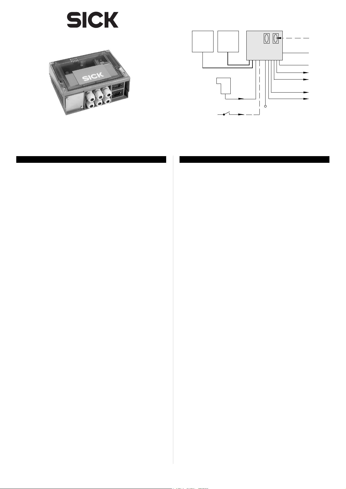
1D/2D
Code
Reader
Lichtschranke
(Lesetakt)
Photo reflex
switch
(Reading clock)
Schalter/switch
Teach-in matchcode
1D/2D
Code
Reader
2 x
“Sensor 1“
2 x
“Sensor 2“
. . . .
. . . . .
CDM420-0004
V
S
. . . .
. . . . .
“Aux“
“CAN“
“Host“
“Result 1“
“Result 2“
“Result 1“
“Result 2“
PC
CAN bus
HOST
(Reader 1)
SPS/
PLC
(Reader 2)
Betriebsanleitung
1. Produkteigenschaften
■ Modular aufgebautes Anschlussmodul zum Anschluss einer Ein-
heit von zwei SICK 1D/2D-Codelesern an Host, CAN-Scanner-
Netzwerk, Feldbussysteme und an Peripherie u. Stromversorgung
■ Unterstützte 1D/2D-Codeleser: Barcodescanner CLV42x ... 45x,
CLV6xx sowie Image Code Reader ICR84x-2, ICR85x-2
■ Basisgerät CDM420-0004 zur optionalen Aufnahme
- eines Cloning-Moduls CMC400/CMC600 für externe Speiche-
rung der Konfigurationsparameter für 1D/2D-Codeleser 1
- eines Display-Moduls CMD400 im optionalen Deckel zur An-
zeige von Leseergebnissen und Lesediagnosedaten des 1D/
2D-Codelesers 1 (Modul nicht anwendbar zusammen mit
Power-Supply-Modul CMP490)
- von Feldbus-Modulen CMF400 zur Anbindung des 1D/2D-
Codelesers 1 an PROFBUS-DP, DeviceNet oder Ethernet TCP/IP
■ Für 1D/2D-Codeleser 1 über CMC600:
zusätzlich zwei Schalteingänge für CLV 42x ... 45x und CLV6xx
sowie zusätzlich zwei Schaltausgänge für CLV6xx
■ Zwei 9-pol. D-Sub-Stecker intern, für Anschluss der seriellen Aux-
Schnittstellen (RS-232) an PC zur Konfiguration/Diagnose der
1D/2D-Codeleser
■ Variante CDM420-0004S01, zusätzlich:
- Power-Supply-Modul CMP490 im optionalen Deckel zur Span-
nungsversorgung der beiden 1D/2D-Codeleser aus einem
Wechselstromnetz
- Serielle Aux-Schnittstellen der 1D/2D-Codeleser zusätzlich
über zwei 9-polige D-Sub-Buchsen auf Frontblende
■ Klemmen für Host-Schnittstelle, CAN-Bus, Schaltein- und
-ausgänge, Stromversorgung, Schirmung
■ Anschluss der 1D/2D-Codeleser über zwei 15-polige D-Sub-HD-
Stecker, Peripherie über Kabelverschraubungen, Feldbus über
systemabhängige Steckverbindungen (Frontblende)
■ Von außen sichtbar: LEDs zur Anzeige von aktiven Schaltein- und
ausgängen sowie Schalterstellungen der Modulkonfiguration
■ Schutzart IP 65 (Variante CDM420-0004S01: IP 20)
■ Wartungsfrei
■ UL-zertifiziert bei Verwendung eines Class 2-Netzgeräts
(geprüft nach UL 1310) zur Stromversorgung
Operating Instructions
1. Features
■ Compact connection module for connecting a unit of two SICK
1D/2D code readers to the host, CAN scanner network, field bus
systems, and to the peripheral equipment and power supply
■ Supported 1D/2D code readers: bar code scanner CLV42x to
45x, CLV6xx or image code reader ICR84x-2, ICR85x-2
■ Basic device CDM420-0004 for integrating optionally the
- CMC400/CMC600 cloning module for saving the 1D/2D code
reader’s 1 configuration parameters externally
- CMD400 display module (installed in a cover variant) for
displaying the reading results and reading diagnosis data of
the 1D/2D code reader 1 (not applicable together with the
CMP490 power supply module)
- CMF400 field bus modules for connecting the 1D/2D code
reader 1 to the PROFBUS-DP, DeviceNet or Ethernet TCP/IP
■ For 1D/2D code reader 1 via CMC600:
additionally two switching inputs for CLV 42x to 45x and CLV6xx
as well as two switching outputs for CLV6xx
■ Two 9-pin internal D-Sub connectors, for connecting the serials
Aux interfaces (RS 232) to a PC for configuring/diagnosing the
1D/2D code readers
■ CDM420-0004S01 version, additionally:
- CMP490 power supply module in optional cover for supplying
power from an AC power line
- Serials Aux interfaces can also be connected via two 9-pin D-
Sub sockets on face plate (front)
■ Terminals for host interface, CAN bus, switching inputs/outputs,
power supply, and shield
■ Connection of the 1D/2D code readers via two 15-pin D-Sub HD
plugs, peripheral equipment via cable glands, and field bus via
system depending plug-in connections on face plate (front)
■ Externally visible LEDs for displaying active switching inputs and
outputs, as well as switch settings for module configuration
■ Enclosure rating IP 65 (CDM420-0004S01 version: IP 20)
■ Maintenance-free
■ UL certificated when a class 2 power supply according to
UL 1310 is used
Weitere Produktinformationen, Programm „CLV-Connect“:
¾ Siehe www.sick.com
Further Product Information, ”CLV-Connect” PC Program:
¾ See www.sick.com
© SICK AG · Division Auto Ident · Germany · All rights reserved 1 # 88011155/S012/2009-04
Page 2
EG-Konformitätserklärung:
¾ Auf Anforderung
EC Conformity Declaration:
¾ On request
HINWEIS
Mögliche Funkstörungen beim Einsatz in Wohngebieten!
Das Anschlussmodul CDM420-0004/CDM420-0004S01 aus-
schließlich in Industrieumgebungen einsetzen.
2. Voraussetzungen zur Installation und Inbetriebnahme
■ Anschlusspläne in CLV-Connect (auf CD-ROM „Manuals & Soft-
ware“, liegt den 1D/2D-Codelesern bei, oder via Internet
www.sick.com)
■ Versorgungsspannung DC 10 ... 30 V nach IEC 742, siehe 5.3
Versorgungsspannung, Seite 3 und 6. Technische Daten, Seite 5
■ Bei Verwendung des Power-Supply-Moduls CMP490 eine
Eingangsspannung von AC 100 ... 250 V, 50 ... 60 Hz
■ Für Barcodescanner CLV6xx ein Anschlussmodul CDM420-0004
/CDM420-0004S01 ab Herstellungsdatum (JJ-WW): 08-07.
Ältere CDM420-0004/-S01 können nicht zusammen mit einem
CLV6xx in Kombination mit einem CMC600 betrieben werden.
3. Montage
■ Freier Zugang zu den internen Steckern „AUX“ erforderlich für
Zugriff auf die 1D/2D-Codeleser (Konfiguration/Diagnose)
■ Max. Leitungslänge zwischen CDM420 und 1D/2D-Codeleser
(Verlängerungsleitungen): 10 m (serielle RS-232-Schnittstelle!)
■ Abgenommener Deckel mit Anschlussbild um 180° gedreht in
Parkposition arretierbar
¾ Bohrungs- und Gehäusemaße siehe Maßbild (Seite 6), max.
Schraubendurchmesser 4 mm.
NOTICE
RF interferences in case of use in residential areas!
The CDM420-0004/CDM420-0004S01 Connection Module is
excusively intended for use in industrial areas.
2. Installation and Commissioning Requirements
■ Connection diagrams in CLV-Connect (on the “Manuals & Soft-
ware“ CD ROM provided with the 1D/2D code readers or from
the Internet: www.sick.com)
■ 10 to 30 V DC power supply generated in accordance with IEC
742, see 5.3 Supply voltage, P. 3 and 6. Techncial Data, P. 6
■ An input voltage of 100 to 250 V AC, 50 to 60 Hz is required
when using the CMP490 Power Supply Module
■ For the CLV6xx Bar Code Scanner a connection module CDM420
-0004/-S01 up from the manufacturing date (jj-ww): 08-07 is
required. Elder CDM420-0004/-S01 can not be used with a
CLV6xx in combination with a CMC600.
3. Installation
■ Free access to internal “AUX” connectors is required to connect
to the 1D/2D code readers (configuration/diagnosis)
■ Max. cable length between CDM420 and 1D/2D code reader
(extension cables): 10 m (32.8 ft) because of serial RS 232 int.
■ Cover with connection diagram can be removed, rotated by
180°, and locked in park position
¾ See dimensional drawing (Page 6) for hole and housing
dimensions, max. screw diameter 4 mm (0.15 in).
Optionale Module:
Einbau und Inbetriebnahme siehe Betriebsanleitung (BA):
■ BA „Parameterspeicher CMC400“ (Nr. 8010002)
■ BA „Parameterspeicher CMC600“ (Nr. 8012120)
■ BA „Display-Modul CMD400“ (Nr. 8010372)
■ BA „Feldbus-Modul CMF400-1x01 (PROFIBUS-DP)“ (Nr. 8010461)
■ BA „Feldbus-Modul CMF400-2101 (DeviceNet)“ (Nr. 8010463)
■ BA „Feldbus-Modul CMF400-3101 (Ethernet)“ (Nr. 8010734)
¾ Optionale Module vor Montage des CDM420 einbauen.
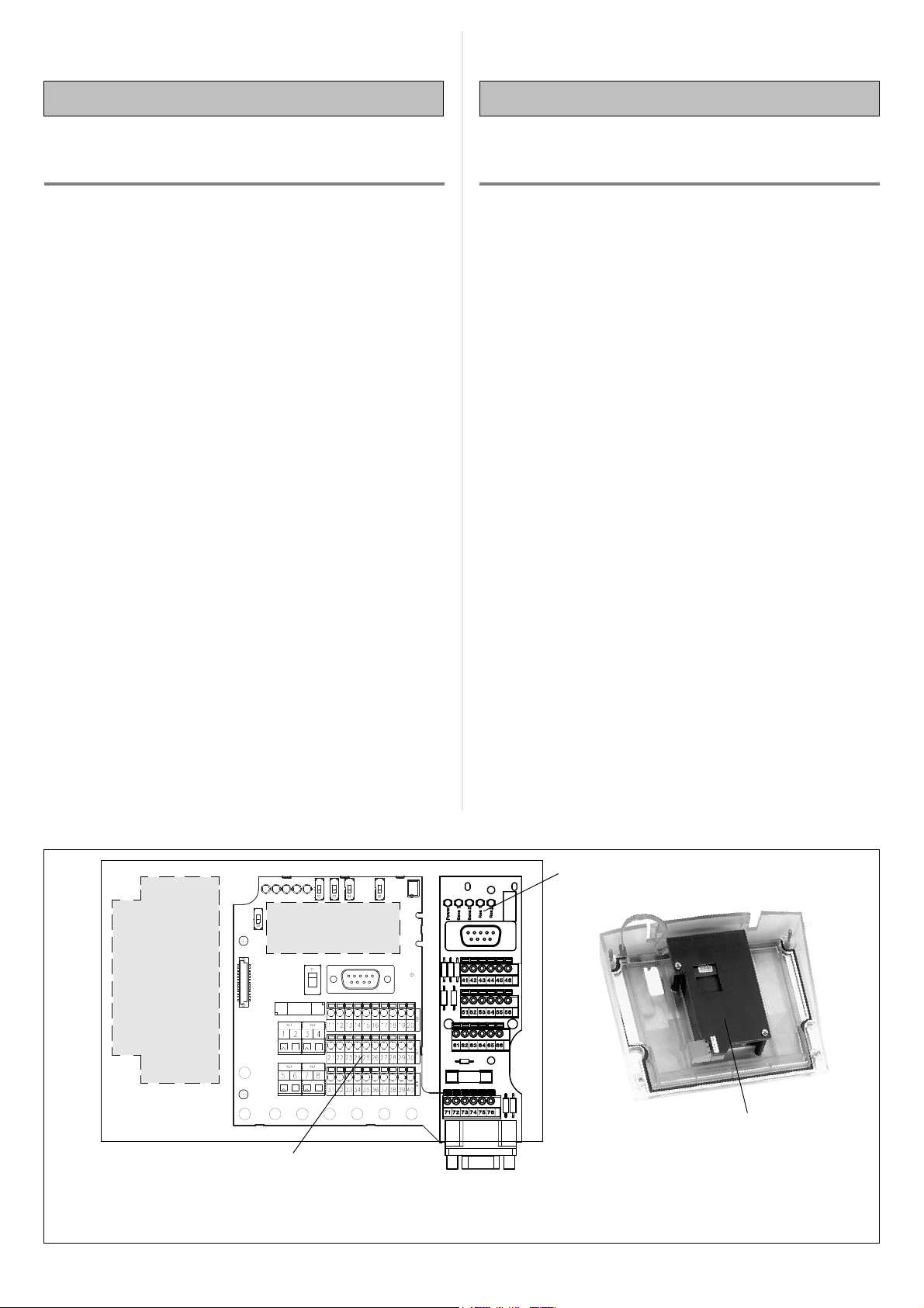
Steckplätze im CDM420-0004/CDM420-0004S01:
Feldbus-Modul
CMF400
CMF400
Field bus module
CMC400/CMC600
Cloning-Modul
Cloning Module
*)
*)
Optional modules:
For installing and commissioning see Operating Instructions (OI):
■ “CMC400 Cloning Module“ OI (no. 8010002)
■ “CMC600 Cloning Module“ OI (no. 8012120)
■ “CMD400 Display Module“ OI (no. 8010372)
■ “CMF400-1x01 Fieldbus Mod. (PROFIBUS-DP)“ OI (no. 8010462)
■ “CMF400-2101 Fieldbus Mod. (DeviceNet)“ OI (no. 8010464)
■ “CMF400-3101 Fieldbus Mod. (Ethernet)“ OI (no. 8010735)
¾ Install the optional modules before mounting the CDM420.
Plug-in slots in the CDM420-0004/CDM420-0004S01:
Anschlusskarte 2 (1D/2D-Codeleser 2)
Connecting board 2 (1D/2D code reader 2)
CDM420-0004S01:
Power-Supply-Modul CMP490 in optionalem Deckel
Anschlusskarte 1 (1D/2D-Codeleser 1)
Connecting board 1 (1D/2D code reader 1)
Hinweis: gleichzeitiger Betrieb des Displays CMD400 und des Power-Supply-Moduls CMP490 nicht möglich.
Note: simultaneous operation of CMD400 Display Module and CMP490 Power Supply Module not possible.
2 # 8 © SICK AG · Division Auto Ident · Germany · All rights reserved 8011155/S012/2009-04
CMP490 Power Supply Module in optional cover
*) nur für 1D/2D-Codeleser 1
for 1D/2D code reader 1 only
Page 3

4. Konfigurationselemente und Anzeigen
Konfigurationsschalter für Codeleser 1 (Anschlusskarte 1):
4. Configuration Elements and Displays
Configuration switches for reader 1 (connecting board 1):
Schalter Funktion Default
S 1 (Power) Anliegende Versorgungsspannung: ON
ON: Versorgungsspannung ein
OFF: Versorgungsspannung aus
S 2 (RS-485) RS-422/485-Umschaltung: OFF
ON: RS-485
OFF: RS-422
S 3 (Trm422) RS-422-Terminierung (Empfänger): OFF
ON: Widerstand 120 Ohm zugeschaltet
OFF: keine Terminierung
S 4 (TrmCAN) Terminierung der CAN-Schnittstelle : OFF
ON: Widerstand 120 Ohm zugeschaltet
OFF: keine Terminierung
S 6 (SGND-GND) Bezugspotenzial für Sensor-GND: ON
ON: verbunden mit GND des 1D/2D-
Codelesers
OFF: potenzialfrei
S 8 (NO CMC) Integration des CMC400/600: NO (oben)
„YES“: CMC in Leitung der Aux-Schnitt-
stelle des 1D/2D-Codelesers
geschaltet
„NO“: kein CMC gesteckt
Funktion der LEDs (Anschlusskarte 1 und 2)
Switch Function Default
S 1 (Power) Connected power supply: ON
ON: Power supply on
OFF: Power supply off
S 2 (RS 485) RS 422/485 selector: OFF
ON: RS 485
OFF: RS 422
S 3 (Trm422) RS 422 termination (receiver): OFF
ON: 120 Ohm resistor connected
OFF: No termination
S 4 (TrmCAN) Termination CAN interface : OFF
ON: 120 Ohm resistor connected
OFF: No termination
S 6 (SGND-GND) Reference potential for sensor GND: ON
ON: Connected to 1D/2D code
reader’s GND
OFF: Floating
S 8 (NO CMC) CMC400/CMC 600 integration (reader): NO (on top)
“YES”: CMC connected to Aux interface
of 1D/2D code reader
“NO”: CMC not connected
Function of LEDs (connecting board 1 and 2):
LED Farbe Funktion
Power grün leuchtet, wenn die Versorgungsspannung am
(Codeleser 1) CDM420 anliegt und Schalter S 1 auf „ON“
Sensor 1, 2 gelb leuchtet, wenn der entsprechende Eingang des
Sen 1,2 1D/2D-Codelesers 1 oder 2 schaltet
Result 1, 2 gelb leuchtet, wenn der entsprechende Ausgang des
Res 1,2 1D/2D-Codelesers 1 oder 2 schaltet
Wichtig:
Codeleser 1: Die zusätzlichen Eingänge Aux In 1 und 2 sowie die
Ausgänge Aux Out 1 und 2 haben keine Statusanzeige durch LEDs.
5. Elektrische Installation
5.1 Datenschnittstellen
Empfohlene Leitungslänge der 1D/2D-Codeleser zum Host:
Schnittstellentyp Datenübertragungsrate Entfernung z. Host
RS-232 bis 19,2 kBd max. 10 m
38,4 ... 57,6 kBd max. 3 m
RS-422/485 max. 38,4 kBd max. 1.200 m
max. 57,6 kBd max. 500 m
5.2 Zusätzliche Schaltein- und Ausgänge für 1D/2D-Codeleser 1
Die Zusatzfunktion des CMC600 unterstützt folgende Geräte:
LED Color Function
Power green Lights up when the power supply is connected
(reader 1) to the CDM420 and switch S 1 is set to “ON“
Sensor 1, 2 yellow Lights up when the corresponding input of the
Sen 1,2 1D/2D code reader 1 or 2 switches
Result 1, 2 yellow Lights up when the corresponding output of the
Res 1,2 1D/2D code reader 1 or 2 switches
Important:
Code Reader 1: The additional inputs Aux In 1 and 2 as well as the
outputs Aux Out 1 and 2 have no status indication by LEDs.
5. Electrical Installation
5.1 Data Interfaces
Recommended cable length from 1D/2D code reader to host:
Interface type Data transfer rate Distance to host
RS 232 Up to 19.2 kBd Max. 10 m (32.8 ft)
38.4 to 57.6 kBd Max. 3 m (9.84 ft)
RS 422/485 Max. 38.4 kBd Max. 1,200 m (3,936 ft)
Max. 57.6 kBd Max. 500 m (1,640 ft)
5.2 Additional switching inputs/outputs for 1D/2D code reader 1
The CMC600 supports the following 1D/2D code readers:
1D/2D-Codeleser zusätzliche Eingänge zusätzliche Ausgänge
CLV42x ... 45x 2 –
CLV6xx 2 2
ICR84x-2/ICR85x-2 – –
5.3 Versorgungsspannung
Der 1D/2D-Codeleser benötigt typenabhängig zur Versorgung
folgende Funktionskleinspannung gemäß IEC 60364-4-41:
1D/2D-Codeleser Versorgungsspannung
CLV42x ... 45x und ICR85x-2 DC 10 ... 30 V
CLV62x / CLV 63x ... CLV65x DC 10 ... 30 V / DC 18 ... 30 V
ICR84x-2 DC 15 ... 30 V
1D/2D code reader Additional inputs Additional outputs
CLV42x to 45x 2 –
CLV6xx 2 2
ICR84x-2/ICR85x-2 – –
5.3 Supply voltage
Dependent on type the 1D/2D code reader requires the following
functional extra-low voltage according to IEC 60364-4-41:
1D/2D code reader Supply voltage
CLV42x to 45x and ICR85x-2 10 to 30 V DC
CLV62x / CLV 63x to CLV65x 10 to 30 V DC / 18 to 30 V DC
ICR84x-2 15 to 30 V DC
© SICK AG · Division Auto Ident · Germany · All rights reserved 3 # 88011155/S012/2009-04
Page 4

HINWEIS
NOTICE
Elektrische Trennung!
Der Ausgangskreis des kundenseitigen Netzgerätes zur Erzeugung
der Versorgungspannung muss gegenüber dem Eingangskreis eine
sichere elektrische Trennung durch Doppelisolation und Sicher-
heitstrafo nach IEC 742 besitzen.
Power-Supply-Modul CMP490 (AC/DC):
GEFAHR
Verletzungsgefahr durch elektrischen Strom!
Das Modul CMP490 wird an Wechselspannung
AC 100 ... 250 V, 50 ... 60 Hz angeschlossen.
¾ Anschluss nur durch ausreichend qualifiziertes Fachpersonal
durchführen lassen.
¾ Sicherheithinweise in der Montageanleitung des CMP490
(Nr. 8010601) beachten.
¾ Schutzleiter an Klemme PE anschließen.
Wichtig:
Durch Verwendung des CMP490 verliert das Anschlussmodul und
die angeschlossenen 1D/2D-Codeleser die UL-Zertifizierung.
Verdrahtung des CDM420-0004/CDM420-0004S01:
■ Elektrische Verbindungen nur im spannungsfreien Zustand
herstellen oder lösen.
■ Für alle Anschlüsse an den Klemmenleisten Kupferleitungen mit
einem Aderquerschnitt von mindestens 0,14 mm2 verwenden.
■ Um den Kurzschluss-/Überlastungschutz der abgehenden Ver-
sorgungsleitungen zu den 1D/2D-Codelesern sicherzustellen, die
verwendeten Aderquerschnitte unter Berücksichtigung der im
CDM420 eingebauten Sicherungen auslegen!
Folgende Normen sind hierbei zu beachten: DIN VDE 0100 (Teil
430), DIN VDE 0298 (Teil 4) bzw. DIN VDE 0891 (Teil 1).
■ Kundenseitige Schirmung am CDM420 auflegen (Kl. „Shield“).
■ Klemmenbelegung siehe Anschlussbild Seite 8 und im Deckel
innen (nur CDM420-0004). Anschlusspläne für Host-/CAN-
Schnittstelle/Schaltein- und -ausgänge siehe CLV-Connect und
Stromlaufpläne (Seite 7 und 8).
■ Variante CDM420-0004S01: Pinbelegung für zusätzliche 9-pol.
D-Sub-Buchsen (serielle Aux-Schnittstellen) siehe Seite 8.
■ Host-Schnittstelle EMV-gerecht über abgeschirmte Leitungen an
den Host anschließen.
■ Um Störeinflüsse zu vermeiden, Leitungen möglichst nicht
parallel zu Stromversorgungs- und Motorleitungen verlegen.
■ Bezugspotenzial für die Schalteingänge mit Schalter S 6 wählen.
■ Integration in CAN-Scanner-Netzwerk: siehe Betriebsanleitung
„Anwendung der CAN-Schnittstelle“ (Nr. 8008179, dt. Ausgabe).
Wichtig:
Die Anschlusskarte 2 (1D/2D-Codeleser 2) hat keinen Schalter um
die zugeführte Versorgungsspannung zu unterbrechen. Auf der
Anschlusskarte 1 ist dies möglich mit dem Schalter S 1.
Electrical isolation!
The output circuit of the customer-specific power supply pack must
be safely electrically isolated from the input circuit by means of
double insulation and a safety isolating transformer according to
IEC 742.
CMP490 Power Supply Module (AC/DC):
DANGER
Shock hazard!
The CMP490 power supply module is connected to a
mains voltage of 100 to 250 V AC/50 to 60 Hz.
¾ The module should only be connected by sufficiently qualified
personnel.
¾ Observe the safety information in the CMP490 Fitting
Instructions (no. 8010601).
¾ Connect the protective conductor to the “PE“ terminal.
Important:
Using the CMP490, the UL certification for the connection module
and the connected 1D/2D code readers is not longer valid.
CDM420-0004/CDM420-0004S01 wiring:
■ Connect or release current linkages only under de-energised
conditions.
■ Use copper cables with a minimum core cross-section of
0.14 mm2 (26 AWG ) for all connections at the terminal strips.
■ To ensure that the outgoing supply cables to the 1D/2D code
readers are protected against short-circuits/overload, the core
cross-sections must be dimensioned in accordance with the
fuses installed in the CDM420. The valid standards must be
observed.
■ Connect the shield of your system to the CDM420 („Shield“
terminal).
■ For terminal assignment, see connection diagram on Page 8 or
inside the cover (CDM420-0004 only). For host/CAN interface/
switching input/output diagrams, see CLV-Connect and circuit
diagram (Page 7 and 8).
■ CDM420-0004S01 version: for the pin assignment of the
additional 9-pin D-Sub sockets (serial Aux interfaces), see Page 8
■ Use shielded cables to establish an EMC-compatible connection
between host interface and host.
■ To prevent interference, do not install cables parallel to power
supply or motor cables (e.g. in cable ducts).
■ Choose reference potential for switching inputs with switch S 6.
■ Integration in CAN scanner network: see Operating Instructions
“Using the CAN Interface” (No. 8008180, English).
Important:
On connection board 2 (1D/2D code reader 2) there is no separate
switch for switching off the power supply. On connection board 1
you can use the switch S 1 to switch off the power supply.
Vorgehensweise:
1. Leitungen der 1D/2D-Codeleser an die beiden 15-pol. D-Sub-HD-
Buchsen des CDM420 anschließen (obere Buchse: 1D/2D-
Codeleser 2, untere Buchse: 1D/2D-Codeleser 1).
2. Alle anderen Leitungen über Kabel-Verschraubungen an Klem-
men auflegen. Um die Schutzart IP 65 zu erhalten, nicht verwen-
dete Durchführungen mit Blindstopfen versehen.
3. CAN-Bus: Falls CDM420 am Busende, Terminierungswiderstand
mit Schalter S 4 zuschalten.
4 # 8 © SICK AG · Division Auto Ident · Germany · All rights reserved 8011155/S012/2009-04
Electrical Installation Procedure:
1. Connect the 1D/2D code reader cables to the two 15-pin D-Sub
HD sockets on the CDM420 (upper socket: reader 2, lower
socket: reader 1).
2. Connect all other cables to the terminals via cable glands.
To remain enclosure rating IP 65, use blanking plugs to close any
unused bushings.
3. CAN bus: if CDM420 is integrated at bus end, enable termination
resistor with switch S 4.
Page 5

4. Mit PC-Programm „CLV-Setup“ Treiber für verdrahtete serielle
Host-Schnittstelle oder CAN-Schnittstelle in den 1D/2D-Code-
lesern jeweils aktivieren (siehe BA der 1D/2D-Codeleser).
Hierzu PC mit 3-adriger RS-232-Datenleitung (Nullmodemleitung)
nacheinander wie folgt anschließen:
- 1D/2D-Codeleser 1: 9-pol. interner Stecker „AUX“ auf Karte 1
- 1D/2D-Codeleser 2: 9-pol. interner Stecker „AUX“ auf Karte 2
Variante CDM420-0004S01:
PC alternativ mit 3-adriger RS-232-Datenleitung (1:1) nacheinan-
der an die 9-pol. Buchsen „AUX“ auf der Frontplatte anschließen.
4. Use the “CLV-Setup” program to activate each the driver for the
connected serial host interface or CAN interface in the 1D/2D
code readers (see the operating instructions for the readers).
To do so, connect the PC to each reader using a 3-core RS 232
data cable (null modem cable) as followed:
- Reader 1: 9-pin internal “AUX“ plug on connecting board 1
- Reader 2: 9-pin internal “AUX“ plug on connecting board 2
CDM420-0004S01 version:
Connect the PC alternatively to the 9-pin “AUX” sockets on the
face plate using a 3-core RS 232 data cable (1:1).
6. Technische Daten
Typ/Bestell-Nr. CDM420-0004 (Standard)/ 1028487
Optische Anzeigen 10 x LED
Elektrische Anschlüsse 2 x 15-pol. D-Sub-HD-Buchse
2 x 9-pol. D-Sub-Stecker
Schraubklemmen, für Adern 0,14 ... 2,5 mm
Federkraftklemmen, für Adern 0,14 ... 1 mm
Kabel-Verschraubungen 6 x (für Leitungen ∅ 4,5 ... 10 mm)
Versorgungsspannung
Leistungsaufnahme
Sicherung 2 x Glasrohrsicherung 0,8 A träge
Gehäuse Polycarbonat
Farbe blau, Deckel transparent
Prüfzeichen CE, UL
Elektrische Sicherheit nach EN 61010-1 (2001-03)
Schutzklasse III3), nach EN 61140 (2002-03)
Schutzart IP 654), nach EN 60529 (1991-10);
EMV-Prüfung nach EN 61000-6-2 (2001-10);
Schwing-/Schockprüfung nach IEC 60068-2-27 (1993)/
Gewicht (Basisgerät) ca. 800 g
Temperat. (Betrieb/Lager) –355) ... +40 °C/ –35 ... +70 °C
Rel. Luftfeuchtigkeit max. 90 %, nicht kondensierend
1) UL-zertifiziert bei Verwendung eines Class 2-Netzgeräts (geprüft nach UL 1310)
2) abhängig von Leser-Typen, ohne Display, Parameterspeicher und Feldbusmodule
3) Klasse I mit Power-Supply-Modul CMP490 und angeschlossenem PE-Leiter
4) bei Verwendung der SICK Scanner-Standardanschlussleitungen
5) in Ruhe (keine Montage oder elektrische Installation), sonst bis –20 °C
Prüfzeichen für UL-Zertifizierung
(nur gültig bei entsprechender Geräte-
kennzeichnung auf dem Typenschild)
1)
DC 10 ... 30 V, SELV bzw. PELV nach
IEC 60364-4-41 (2005)
DC 18 ... 30 V bei Verwendung von Display
CMD400 und/oder Feldbusmodulen
2)
P
+ 0,5 W
Scanner
A1 (2002-02)
EN 61000-6-4 (2001-10); EN 55011
(1998-05), A1 (1999-08), A2 (2002-10)
nach IEC 60068-2-6 (1995)
6. Technical Data
Type/order no. CDM420-0004 (standard type)/ 1028487
Visual indicators 10 x LED
Electrical connections 2 x pair of 15-pin D-Sub HD socket
2
2
Cable glands 6 x, for cables ∅ 4.5 to 10 mm
Power supply
1)
Power consumption
Fuse 2 x glass tube fuse 0.8 A, type T
Housing/Colour Polycarbonate/blue, transparent cover
Conformity CE, UL
Electrical safety To EN 61010-1 (2001-03)
Protection class III3), to EN 61140 (2002-03)
Enclosure rating IP 654), to EN 60529 (1991-10); A1 (2002-02)
EMC tested To EN 61000-6-2 (2001-10);
Vibration/shock test to IEC 60068-2-27 (1993)/IEC 60068-2-6 (1995)
Weight (basic device) Approx. 800 g (approx. 28.2 oz)
Temperature –355) to +40 °C/ –35 to +70 °C
(operation/storage) (–315) to +104 °F/ –31 to +158 °F)
Rel. air humidity Max. 90 %, non-condensing
1) UL certificated when a Class 2 power supply according to UL 1310 is used
2) Reader type specific, without display, cloning module und field bus modules
3) Class I with CMP490 power supply module and connected PE conductor
4) With SICK standard scanner cables
5) Without any mounting or electrical installation work, otherwise –20 °C (–4 °F)
Conformity symbol of UL certification
(valid only with corresponding product
marking on the nameplate)
2 x 9-pin D-Sub plug
Screw terminals, for cores 0.14 to 2.5 mm
(approx. 26 to 13 AWG), spring terminals, for
cores 0.14 to 1 mm2 (approx. 26 to 17 AWG)
(diam. 0.18 to 0.39 in)
10 to 30 V DC, SELV respectively PELV to
IEC 60364-4-41 (2005),
18 to 30 V DC when using the CMD400
display and/or field bus modules
2)
P
+ 0.5 W
Scanner
to EN 61000-6-4 (2001-10); to EN 55011
(1998-05), A1 (1999-08), A2 (2002-10)
2
7. Zubehör
Bestell-Nr. Beschreibung
1023850 CMC400-101 Cloning-Modul
1042259 CMC600-101 Cloning-Modul
2029466 CMD400 Display-Modul
1026241 CMF400-1001 Feldbus-Modul
1026643 CMF400-1101 Feldbus-Modul
1026242 CMF400-2101 Feldbus-Modul
1026357 CMF400-3101 Feldbus-Modul
6010075 Verlängerungsleitung für CLV42x ... 45x, ICR84x-2, ICR85x-2,
CLV6xx, 2 m, geschirmt, mit 15-pol. D-Sub-HD-Steck./Buchse
1) Betriebstemperatur 0 ... +40 °C 2) nur für 1D/2D-Codeleser 1
3) nicht für CDM420-0004S01
1)2)
für CLV42x ... 45x
1)2)
für CLV6xx, ICR84x-2/85x-2
1)2)3)
, 4 x 20 Zeichen, 5 Tasten
1)2)
für PROFIBUS-DP, IP 20
1)2)
für PROFIBUS-DP, IP 65
1)2)
für DeviceNet, IP 65
1)2)
für Ethernet TCP/IP, IP 65
7. Accessories
Order No. Description
1023850 CMC400-101 cloning module
1042259 CMC600-101 cloning module
2029466 CMD400 display module
1026241 CMF400-1001 field bus module
1026643 CMF400-1101 field bus module
1026242 CMF400-2101 field bus module
1026357 CMF400-3101 for bus module
6010075 Extension cable for CLV42x to 45x, ICR84x-2/85x-2, CLV6xx
2 m (6.56 ft), shielded, with 15-pin D-Sub HD plug/socket
1) Operating temperature 0 to +40 °C (+32 to +104 °F)
2) only for 1D/2D code reader 1 3) not for CDM420-0004S01
© SICK AG · Division Auto Ident · Germany · All rights reserved 5 # 88011155/S012/2009-04
1)2)
for CLV42x to 45x
1)2)
for CLV6xx, ICR84x-2/85x-2
1)2)3)
, 4 x 20 digits, 5 keys
1)2)
for PROFIBUS-DP, IP 20
1)2)
for PROFIBUS-DP, IP 65
1)2)
for DeviceNet, IP 65
1)2)
for Etherrnet TCP/IP, IP 65
Page 6

Bestell-Nr. Beschreibung
2014054 RS-232-Datenleitung (Nullmodemleitung), 3 m, geschirmt,
mit 2 x 9-pol. D-Sub-Buchse, zum Anschluss an die 9-pol.
D-Sub-Stecker „AUX“ im Inneren des CDM420-0004
6005695 Datenleitung , Meterware, twisted pair, geschirmt, für
RS-232 und RS-422/485-Schnittstellen
6027048 Datenleitung CAN-BUS, Meterware, twisted pair, geschirmt
Order No. Description
2014054 RS 232 data cable (null modem cable), 3 m (9.84 ft),
shielded, with 2 x 9-pin D-Sub socket for connecting to the
9-pin D Sub plugs “AUX“ inside of the CDM420-0004
6005695 Data cable, cut to size, twisted pair, shielded, for
RS 232 and RS 422/485 interfaces
6027048 CAN BUS data cable, cut to size, twisted pair, shielded
8. Fehlersuche für Basisgerät CDM420-0004
Störung
• Versorgungsspg. angeschlossen
aber LED „Power“ leuchtet nicht
• Signale des am 1D/2D-Codeleser
1 angeschlossenen Lesetaktsensors bleiben wirkungslos
• Nach Anschluss des PCs an den
Stecker „AUX“ auf Anschlusskarte
1 oder 2 kein Zugriff auf den
1D/2D-Codeleser mit CLV-Setup
Wichtig: Fehlersuche in Zusammenhang mit optionalen Modulen
siehe jeweils deren Betriebs-/Montageanleitung.
Abhilfe
• Leser 1: Schalter S 1 (Power) in
Position „ON“ bringen
• Lesetaktsensor gemäß CLV-
Connect anschließen
• Schalter S 6 in richtige Position
bringen (siehe Stromlaufplan)
• Mit Hilfe von „CLV-Setup“ die
Quelle des Lesetakts im 1D/2DCodeleser 1 auf „Sensor 1“
einstellen. Download!
• Wenn kein CMC400/600 für 1D/
2D-Codeleser 1 gesteckt, Schalter S 8 auf Position „NO“ stellen
• Mit Hilfe der Funktion
„AutoBaudDetect“ in „CLV-Setup“
die Kommunikationsparameter
des PC automatisch wählen
Maßbild/dimensioned drawing
8. Troubleshooting for CDM420-0004 (Basic Device)
Malfunction
• “Power” LED does not light up
when power supply is connected
• Signals from connected reading
clock sensor have no effect on
the 1D/2D code reader 1
• Cannot access 1D/2D code
reader with CLV-Setup after
connecting the PC to the “AUX”
connector on the connecting
board 1 or 2
Important: For troubleshooting of the optional modules see the
respective operating or fitting instructions.
Remedy
• Reader 1: Set switch S 1 (Power)
to “ON”
• Connect reading pulse sensor in
accordance with CLV-Connect
• Set switch S 6 to correct position
(see circuit diagram)
• Using “CLV-Setup”, set the reading
clock source for each 1D/2D code
reader 1 to “Sensor 1”.
Download to the readers.
• If no CMC400/600 is connected
for 1D/2D code reader 1, set
switch S 8 to “NO”
• Using the “AutoBaudDetect”
function in “CLV-Setup” to configure the PC communication
parameters automatically
Nur bei Typ CDM420-0004S01:
Type CDM420-0004S01 only:
Reader 2
Reader 1
Alle Dimensionen in mm (inch)
All dimensions in mm (inch)
Reader 2
Reader 1
Erforderlicher Anschlussraum für Stecker
Space required for connecting plug
Erforderlicher Anschlussraum für Stecker bei optionaler Blende
Space required for connecting plugs when using optional face plate
6 # 8 © SICK AG · Division Auto Ident · Germany · All rights reserved 8011155/S012/2009-04
Page 7

Stromlaufplan Anschlusskarte 1 (1D/2D-Codeleser 1)/circuit diagram of connecting board 1 (1D/2D code reader 1)
AUX plug
15-pin D-Sub HD socket to scanner
S5: Switch for CAN_2 termination
S4: Switch for CAN termination
to CMC module
+24V_Heating_Out
(no scanner connected)
For MPX module
S3: Switch for RS485 termination
S7: Switch RS232 CLV41x: Terminal <—> AUX
V1: CDM420 for CLV42x / CLV43x / CLV44x /CLV45x / CLV6xx/ ICR84x-2 / ICR85x-2
V2: CDM410 for CLV41x
V3: CDM490 for CLV49x / LMS400
S2: Switch RS422 <—> RS485
V4: CDM4xx for operation with CMX module for CAN multiplexer
S6: Switch INGND — GND
to CMF400 bus module
+24V_Heating_Out
4-pin to CMP
4-pin to I/O board
© SICK AG · Division Auto Ident · Germany · All rights reserved 7 # 88011155/S012/2009-04
Page 8

Stromlaufplan Anschlusskarte 2 (1D/2D-Codeleser 2)
15
69
15
69
Circuit diagram of connecting board 2 (1D/2D code reader 2)
Interne Verbindungsleitungen
Internal connecting cables
Anschlusskarte 1 Anschlusskarte 2
Connecting board 1 Connecting board 2
Klemme Signal Aderfarbe Klemme
Terminal Wire colour Terminal
21 CAN_H weiss/white 61
22 CAN_L blau/blue 62
3Vsrot/red 71
4 GND schwarz/black 72
8 Shield grau/grey 73
CDM420-0004S01:
Pinbelegung 9-pol. D-Sub-Buchsen auf Frontblende
Pin assignment of 9-pin D-Sub sockets on front
Aufbau, Klemmenbelegung/design, terminal assignment
LEDs
Konfigurationsschalter
Configuration switches
(Reader 2)
(Reader 1)
Klemmenleisten für
Versorgungsspannung
Terminal strips for power
supply voltage
Pin Signal
1 not connected
2 TxD (RS 232), AUX
3 RxD (RS 232), AUX
4 not connected
5 GND
6 not connected
7 not connected
8 not connected
9 not connected
LEDs
Power
Anschluss PC
PC connection
Sens 2
Sens 1
Res 1
AUX interface
Res 2
Sens 1
Sens 2
GND
GND
41 42 43 44 45 46
CAN_L
CAN_H
GNDT+GND
51 52 53 54 55 56
CAN_L
GNDT–GND
R–
Shield
GND
RxD
GND
TxD
8011155/S012/2009-04 · 5M/TR <PM 6.5> · VD · Printed in Germany · Subject to change without prior notice · The specified product features and technical data do not represent any guarantee · AftE6205sw
Klemmenleisten
1D/2D-Codeleser
Terminal strips for
1D/2D code reader
Konfigurationsschalter
Configuration switches
Anschluss
1D/2D-Codeleser
1D/2D code reader
connection
Anschluss PC
PC connection
Klemmenleisten
1D/2D-Codeleser
Terminal strips
for 1D/2D code
reader
Anschluss
1D/2DCodeleser
1D/2D code
CAN_H
61 62 63 64 65 66
+24 V
71 72 73 74 75 76
reader
connection
Reader 1 Reader 2
8 # 8 © SICK AG · Division Auto Ident · Germany · All rights reserved 8011155/S012/2009-04
SICK AG · Waldkirch · Germany · www.sick.com
Result 2
Result 1
R+
 Loading...