

Page 1
1 # 88012119/WE04/2012-07 © SICK AG · Germany · All rights reserved · Subject to change without notice · Irrtümer und Änderungen vorbehalten
“Sensor 2”
CDB620
1. Produkteigenschaften
■ Basis-Anschlussmodul zum Anschluss eines SICK Identifikations-
sensors (ID-Sensor) an Host, CAN-Scanner-Netzwerk, Peripheriegeräte und Stromversorgung
■ Unterstützte Identifikationssensoren:
Barcodescanner CLV42x ...45x, CLV6xx (nicht CLV69x),
CLV480 oder CLV/X490, kamera-basierte Code Reader
LECTOR
620, ICR84x-2/85x-2 und RFID-Interrogatoren RFH6xx
■ Basis zur Aufnahme eines optionalen CMC600 (Connection
Module Cloning) für externe Speicherung der Konfigurationsparameter des Identifikationssensors. Dient auch der Aktivierung
von Betriebsarten und Erweiterung des Sensors um jeweils zwei
digitale Schaltein- und -ausgänge (abhängig vom Sensortyp)
■ 9-pol. D-Sub-Stecker intern, für Anschluss der seriellen Aux-
Schnittstelle (RS-232) an PC zur Konfiguration/Diagnose des
Identifikationssensors
■ Klemmen für serielle Host-Schnittstelle, CAN-Bus (CDB620-101:
2x M12-Steckverbindungen), Schaltein- und -ausgänge, Stromversorgung, Schirmung
■ Von außen sichtbar: LEDs zur Anzeige von aktiven Schaltein- und
ausgängen sowie Schalterstellungen der Modulkonfiguration
■ Schutzart IP 65 (nicht durch UL geprüft)
■ Betriebsumgebungstemperaturbereich –35 ... +40 °C
■ Montierbar bei geschlossenem Deckel
■ Wartungsfrei
■ UL-zertifiziert bei Verwendung eines folgenden Netzgeräts:
UL60950-1: LPS- oder Class-2-Netzgerät
UL508: Class-2-Netzgerät
Weitere Produktinformationen, EG-Konformitätserklärung,
PC-Programm „CLV-Connect“:
Siehe Produktseite im Internet (www.sick.com)
2. Voraussetzungen zur Installation und Inbetriebnahme
■ Anschlusspläne in CLV-Connect (auf DVD/CD „Manuals &
Software“, die dem Sensor beiliegt, oder via Internet)
■ Versorgungsspannung DC 24 V, erzeugt nach IEC 742
■ Montage-, Anschluss- und Konfigurationsarbeiten nur im Be-
triebsumgebungstemperaturbereich 0 ... +40 °C vornehmen!
Anschlussmodul
Betriebsanleitung Operating Instructions
Connection Module
1. Features
■ Basic module for connecting a SICK identification sensor
(ID sensor) to the host, CAN scanner network, peripheral
equipment, and power supply
■ Supported identification sensors:
Bar code scanners CLV 42x to 45x, CLV6xx (not CLV69x),
CLV480 or CLV /X490, image-based code readers LECTOR
620,
ICR84x-2/85x-2, and RDIF Interrogators RFH6xx
■ Basis for optional CMC600 (Connection Module Cloning) inte-
gration for external storage of the identification sensor’s configuration parameters. Also for activation of operating modes as well
as for extension of the sensor with each of two digital switching
inputs and outputs (depends on sensor type)
■ 9-pin internal D-Sub plug, for connecting the serial Aux interface
(RS 232) to a PC for configuring/troubleshooting the identification sensor
■ Terminals for serial host interface, CAN bus (CDB620-101: 2 x
M12 connections), switching inputs/outputs, power supply, and
shield
■ Externally visible LEDs for displaying active switching inputs and
outputs, as well as switch settings for module configuration
■ Enclosure rating IP 65 (not tested by UL)
■ Operation ambient temperature range –35 to +40 °C
(–31 to +104 °F)
■ Installation possible with closed cover
■ Maintenance-free
■ UL certificated when the following power supply is used:
UL60950-1: LPS or Class 2 power supply
UL508: Class 2 power supply
Further Product Information, EC Conformity Declaration, “CLVConnect” PC Program:
See product page on the Internet (www.sick.com)
2. Installation and Commissioning Requirements
■ Connection diagrams in CLV-Connect (on the “Manuals & Soft-
ware” DVD/CD, provided with the sensor or from the Internet)
■ 24 V DC power supply generated in accordance with IEC 742
■ Perform mounting, electrical connection and configuration works
only at operation ambient temperature range 0 to +40 °C (+32
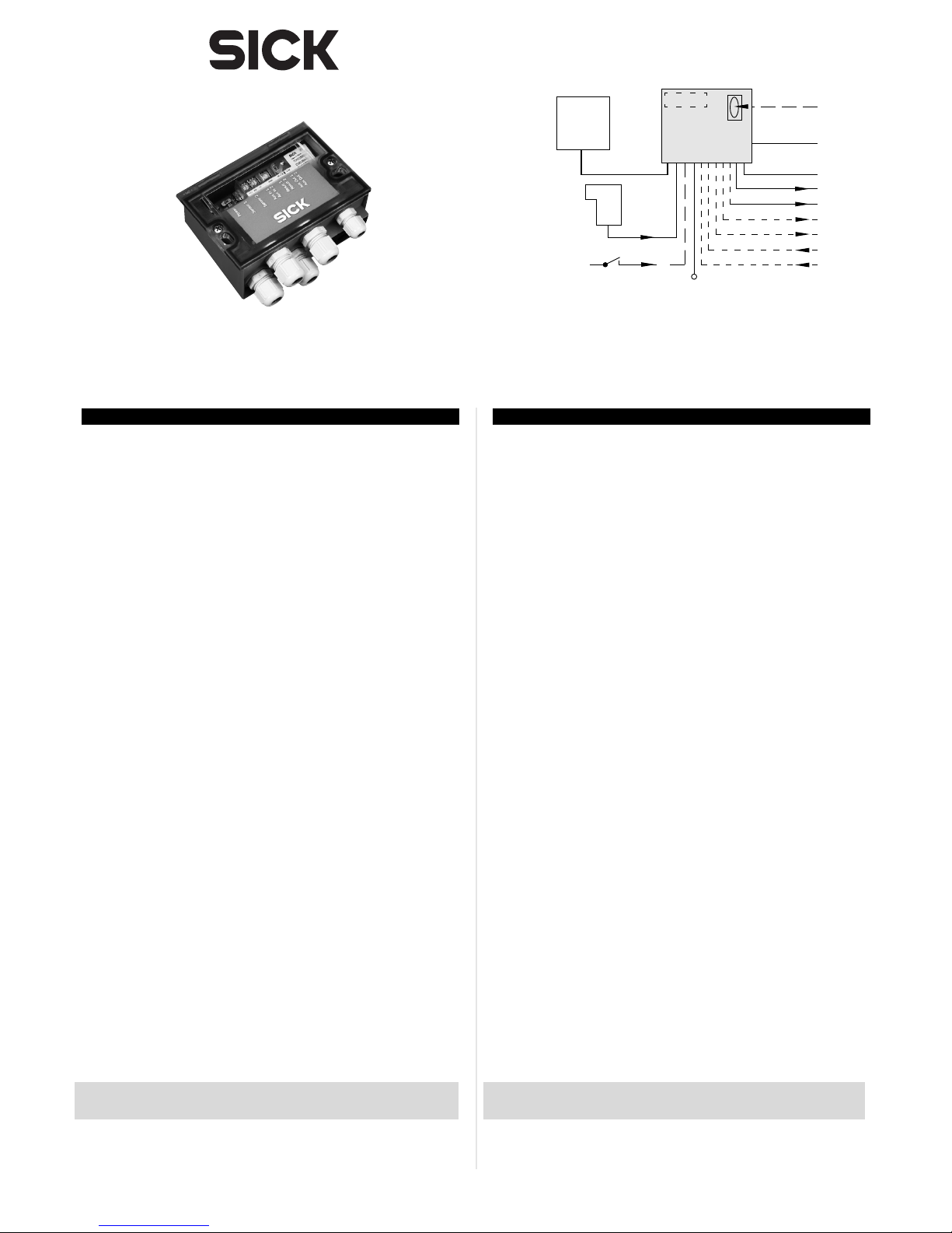
“Host”
10 ... 30 V DC
“Sensor 1”
“Result 1”
Lichtschranke
(Lesetakt)
Photo reflex
switch
(Reading clock)
Schalter/switch
Teach-in matchcode
“Aux”
PC
HOST
SPS/PLC
ID
Sensor
CDB620
. . . .
. . . . .
“CAN”
CAN bus
“Result 2”
SPS/PLC
CMC600
“Out 1”
“Out 2”
“In 1”
“In 2”
Page 2
2 # 8 8012119/WE04/2012-07© SICK AG · Germany · All rights reserved · Subject to change without notice · Irrtümer und Änderungen vorbehalten
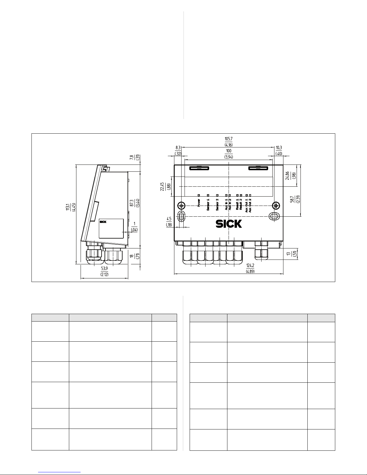
Maßbild/dimensioned drawing
Alle Angaben in mm (inch)/All dimensions in mm (inch)
4. Konfigurationselemente und Anzeigen
4.1 Funktion der Konfigurationsschalter
Schalter Funktion Default
S 1 (Power) Anliegende Versorgungsspannung: ON
ON: Versorgungsspannung UIN* ein
OFF: Versorgungsspannung UIN* aus
S 2 (CAN-Term) Terminierung des CAN-Busses: OFF
ON: Widerst. 120 Ohm zugeschaltet
OFF: keine Terminierung
S 3 (SGND-GND) Bezugspotenzial für Sensor-GND: OFF
ON: verbunden mit GND des ID-Sensors
OFF: potentialfrei
S 4 (CMC) Integration des CMC600: NO
„YES“: CMC600 in Leitung der AuxSchnittstelle des ID-Sensors geschaltet
„NO“: kein CMC600 gesteckt
S 6 (RS-485) RS-422/485-Umschaltung OFF
ON: RS-485
OFF: RS-422
S 7 (Term422) RS-422-Terminierung (Empfänger) OFF
ON: Widerst. 120 Ohm zugeschaltet
OFF: keine Terminierung
4. Configuration Elements and Displays
4.1 Configuration Switches
Switch Function Default
S 1 (Power) Power supply: ON
ON: Supply voltage UIN* on
OFF: Supply voltage UIN* off
S 2 (CAN-Term) CAN bus termination: OFF
ON: 120 Ohm resistor connected
OFF: No termination
S 3 (SGND-GND) Reference potential for sensor GND: OFF
ON: Connected to ID sensor GND
OFF: Floating
S 4 (CMC) CMC600 integration: NO
“YES”: CMC600 connected to Aux
interface of the ID sensor
“NO”: CMC600 not connected
S 6 (RS 485) RS 422/485 selector OFF
ON: RS 485
OFF: RS 422
S 7 (Term422) RS 422 termination (receiver): OFF
ON: 120 Ohm resistor connected
OFF: No termination
Einsatz im Betriebsumgebungstemperaturbereich 0 ... –35 °C
nur im Zustand der Ruhe (keine Montage-, Anschluss- oder
Konfigurationsarbeiten).
3. Montage
■ Stets freier Zugang zum internen Stecker „AUX“ erforderlich für
Zugriff auf den ID-Sensor über RS-232 (Konfiguration/Diagnose)
■ Maximale Leitungslänge zwischen CDB620 und ID-Sensor beim
Einsatz von Verlängerungsleitungen: 10 m (RS-232-Schnittstelle!)
■ Abgenommener Deckel mit Anschlussbild um 180° gedreht in
Parkposition arretierbar
Bohrungs- und Gehäusemaße siehe Maßbild, max. Schrauben-
durchmesser 4 mm.
Einbau und Inbetriebnahme des optionalen CMC600 siehe
„Betriebsanleitung CMC600-101“ (Nr. 8015190)
to +104 °F)! Application of the module at operation ambient
temp. range 0 to –35 °C (+32 to –31 °F) only in rest status
(without any mounting, electrical installation or config. works).
3. Installation
■ Permanent access to internal “AUX” plug is required for access to
the ID sensor via RS 232 (configuration/troubleshooting)
■ Max. cable length between CDB620 and ID sensor if extension
cables are used: 10 m (32.8 ft) because of RS 232 interface
■ Cover with connection diagram can be removed, rotated through
180°, and locked in park position
See dimensioned drawing for hole and housing dimensions, max.
screw diameter 4 mm (0.15 in).
For installing and commissioning the optional CMC600, see
“CMC600-101 Operating Instructions” (no. 8015190).
Abb. 1: Abmessungen des CDB620/Fig. 1: Dimensions of the CDB620
Page 3
3 # 88012119/WE04/2012-07 © SICK AG · Germany · All rights reserved · Subject to change without notice · Irrtümer und Änderungen vorbehalten
5. Electrical Installation
5.1 Data Interfaces
Recommended max. cable length from ID sensor to host
:
4.2 Funktion der LEDs
LED Farbe Funktion
Power Grün Leuchtet, wenn die Versorgungsspannung
(UIN*) am CDB620 anliegt und Schalter S 1 auf „ON“
Sensor 1, 2 Grün Leuchtet, wenn der entsprechende (zusätzliche)
In 1*), 2
*)
Eingang des ID-Sensors (über CMC600) schaltet
Result 1, 2 Orange Leuchtet, wenn der entsprechende (zusätzliche)
Out 1*), 2
*)
Ausgang des ID-Sensors (über CMC600) schaltet
*) Voraussetzung ist das Modul CMC600
5. Elektrische Installation
5.1 Datenschnittstellen
Empfohlene max. Leitungslänge vom ID-Sensor zum Host:
5.3 Versorgungsspannung U
IN
Der ID-Sensor benötigt typenabhängig zur Versorgung folgende
Funktionskleinspannung gemäß IEC 60364-4-41:
4.2 LEDs
LED Color Function
Power Green Lights up when the power supply is connected
(UIN*) to the CDB620 and switch S 1 is set to “ON”
Sensor 1, 2 Green Lights up when the corresponding (additional)
In 1*), 2
*)
ID sensor input switches (via CMC600)
Result 1, 2 Orange Lights up when the corresponding (additional)
Out 1*), 2
*)
ID sensor output switches (via CMC600)
*) A CMC600 module is required
Interface type Data transfer rate Distance to host
RS 232 Up to 19.2 kBd Max. 10 m (32.8 ft)
38.4 to 57.6 kBd Max. 3 m (9.84 ft)
RS 422 Max. 38.4 kBd Max. 1,200 m (3,936 ft)
Max. 57.6 kBd Max. 500 m (1,640 ft)
Schnittstellentyp Datenübertragungsrate Entfernung z. Host
RS-232 Bis 19,2 kBd Max. 10 m
38,4 ... 57,6 kBd Max. 3 m
RS-422 Max. 38,4 kBd Max. 1.200 m
Max. 57,6 kBd Max. 500 m
Identifikationssensor Versorgungsspannung
CLV42x ... 45x /ICR85x-2 DC 10 ... 30 V
CLV6xx/RFH6xx/LECTOR620 DC 10 ... 30 V
CLV6xx mit Heizung DC 24 V 10 %
ICR84x-2 DC 15 ... 30 V
CLV480, CLV/CLX490 ohne Heizung DC 18 ... 30 V
CLV480, CLV/CLX490 mit Heizung DC 24 V +20 %/–10 %
5.2 Zusätzliche Schaltein- und Ausgänge
Die Zusatzfunktion des CMC600 unterstützt folgende ID-Sensoren:
Identifikationssensor Zusätzl. Eingänge Zusätzl. Ausgänge
CLV42x ... 45x 2 –
CLV6xx/RFH6xx/LECTOR620 2 2
ICR84x-2/ICR85x-2 – –
CLV480, CLV/CLX490 – –
5.3 Supply voltage U
IN
Depending on type, the ID sensor requires the following functional
extra-low voltage according to IEC 60364-4-41 for power supply:
Identification sensor Supply voltage
CLV42x to 45x /ICR85x-2 10 to 30 V DC
CLV6xx /RFH6xx/LECTOR620 10 to 30 V DC
CLV6xx with heating 24 V DC 10 %
ICR84x-2 15 to 30 V DC
CLV480, CLV/CLX490 with heater 18 to 30 V DC
CLV480, CLV/CLX490 without heater 24 V DC +20 %/–10 %
5.2 Additional switching inputs and outputs
The CMC600 supports the following ID sensors:
Identification sensor Additional inputs Additional outputs
CLV42x to 45x 2 –
CLV6xx/RFH6xx/LECTOR620 2 2
ICR84x-2/ICR85x-2 – –
CLV480, CLV/CLX490 – –
Verletzungsgefahr durch elektrischen Strom!
Wird die Versorgungsspannung durch ein Netzgerät
erzeugt, kann mangelhafte elektrische Trennung
zwischen Eingangs- und Ausgangskreis des Netzgeräts zu einem Stromschlag führen.
GEFAHR
Nur ein Netzgerät verwenden, dessen Ausgangskreis gegenüber
dem Eingangskreis eine sichere elektrische Trennung durch
Doppelisolation und Sicherheitstrafo nach IEC 742 besitzt.
5.4 Verdrahtung des CDB620
■ Elektroinstallation nur durch ausgebildetes Fachpersonal
durchführen.
■ Bei Arbeiten in elektrischen Anlagen die gängigen Sicherheits-
vorschriften beachten.
■ Elektrische Verbindungen nur im spannungsfreien Zustand her-
stellen oder lösen.
■ Um den Kurzschluss-/Überlastungschutz der abgehenden Ver-
sorgungsleitungen (U
IN
*) zum ID-Sensor sicherzustellen, müssen
Risk of injuries due to electrical current!
If the supply voltage is provided by a power supply
unit, insufficient electrical insulation between input
and output circuit of the unit can cause an electric
shock.
DANGER
Only use a power supply unit which output circuit is safely electri-
cally isolated from the input circuit by means of double insulation
and a safety isolating transformer according to IEC 742.
5.4 Wiring the CDB620
■ Electrical installation should only be carried out by qualified staff.
■ Observe the current safety regulations when working on electri-
cal systems.
■ Connect or disconnect current linkages only under de-energized
conditions.
■ To ensure that the outgoing supply cables (U
IN
*) to the ID sensor
are protected against short-circuits/overload, the core crosssections must be dimensioned in accordance with the fuse
Page 4

4 # 8 8012119/WE04/2012-07© SICK AG · Germany · All rights reserved · Subject to change without notice · Irrtümer und Änderungen vorbehalten
Aufbau, Klemmenbelegung/design, terminal assignment
LEDs
Konfigurationsschalter
Configuration switches
Anschluss ID-Sensor
ID Sensor connection
Klemmenleisten
Terminal strips
Anschluss PC
PC connection
Steckplatz für CMC600
Plug-in slot for CMC600
CAN
bus
“Host”
“Result 1”
“Sensor 1”
ID sensor
ID sensor
ID sensor
CDB620
CDB620
CDB620
Schema: Aufbau eines CAN-Scanner-Netzwerkes
Diagram: Building a CAN scanner network
CDB620-101: Pinbelegungen der M12Steckverbindungen siehe unten.
CDB620-101: For pin assignment of the
M12 connections see below
CDB620-101:
Pinbelegung M12-Steckverbindungen / pin assignment of M12 connectors
Pin Signal
1 Schirm/Shield
2V
s
3 GND
4 CAN H
5 CAN L
Buchse (A-kodiert)
socket (A-type encoded)
CAN bus
Pin Signal
1 Schirm/Shield
2V
s
3 GND
4 CAN H
5 CAN L
CAN bus
die verwendeten Aderquerschnitte unter Berücksichtigung
der im CDB620 eingebauten Sicherung ausgelegt werden.
Folgende Normen sind hierbei zu beachten: DIN VDE 0100
(Teil 430), DIN VDE 0298 (Teil 4) bzw. DIN VDE 0891 (Teil 1)
■ Klemmenbelegung siehe Anschlussbild unten oder im
Deckel. Anschlusspläne für Host-Schnittstelle/CAN-Schnittstelle/Schaltein- und -ausgänge siehe CLV-Connect.
■ Integration in CAN-Scanner-Netzwerk: siehe Betriebsanlei-
tung „Anwendung der CAN-Schnittstelle“ (Nr. 8008179, dt.
Ausgabe).
■ Um Störeinflüsse zu vermeiden, Leitungen möglichst nicht
parallel zu Stromversorgungs- und Motorleitungen verlegen
■ Bezugspotenzial für die Schalteingänge mit Schalter S 3
(siehe Seite 2) wählen
1. Leitung des Sensors an 15-pol. D-Sub-HD-Bu. anschließen.
2. Alle anderen Leitungen über Kabel-Verschraubungen an den
Klemmen auflegen.
3. Anwenderseitige Schirmung am CDB620 auflegen (Klemme
„Shield“)
4. CAN-Bus: Falls CDB620 am Busende, Terminierungswiderstand mit Schalter S 2 (siehe Seite 2) zuschalten
Mit Konfigurationssoftware CLV-Setup/SOPAS-ET den Treiber
für verdrahtete serielle Host-/CAN-Schnittstelle im ID-Sensor
aktivieren (siehe Betriebsanleitung des ID-Sensors).
Hierzu PC mit 3-adriger RS-232-Datenleitung (Nullmodemleitung) an Stecker „AUX“ im CDB620 anschließen oder IDSensor über Ethernet kontaktieren (abhängig v. Sensortyp).
installed in the CDB620. The valid national standards must be
observed.
■ For terminal assignment, see connection diagram below or
inside the cover. For host/CAN interface/switching inputs/
outputs diagrams, see CLV-Connect.
■ Integration in CAN scanner network: see operating instructions
“Using the CAN Interface” (no. 8008180, English).
■ To prevent interference, do not lay cables parallel to power
supply or motor cables
■ Choose reference potential for switching inputs with switch S 3
(see page 2)
1. Connect the ID sensor cable to the 15-pin D-Sub HD socket.
2. Connect all other cables to the terminals provided using cable
glands (only when the power supply is switched off).
3. Connect the shield of your system to the CDB620 (“Shield”
terminal).
4. CAN bus: if CDB620 is integrated at bus end, connect termination resistor with switch S 2 (see page 2)
Using CLV-Setup/SOPAS-ET configuration software, activate the
driver for the connected serial host/CAN interface in the ID
sensor (see the operating instructions of the ID sensor).
To do so, connect the PC to the “AUX” plug on the CDB620
using a 3-core RS 232 data cable (null modem cable) or
establish communication to the ID sensor via Ethernet
(depends on sensor type).
Abb. 2: Belegung der Klemmen und Schalter/Fig. 2: Functional attribution of terminals and switches
Stecker (A-kodiert)
plug (A-type encoded)
Page 5

5 # 88012119/WE04/2012-07 © SICK AG · Germany · All rights reserved · Subject to change without notice · Irrtümer und Änderungen vorbehalten
6. Elektrische Sicherheit: Gefahr durch Ausgleichsströme
bei unterschiedlichen Erdpotentialen
6.1 Änderung der Norm 60950-1
Die Norm 60950-1 (2006-04) wurde mit der Änderung A11 (2009-
03) erweitert. Die Änderung ist ab 01-12-2010 verbindlich.
Das CDB620 ist auf elektrische Sicherheit gemäß dieser geänderten Norm ausgelegt und geprüft.
6.2 Voraussetzungen für den sicheren Betrieb des CDB620 und
des daran angeschlossenen SICK Sensors
Die SICK Sensoren werden jeweils über ein CDB620 mit geschirmten Leitungen an die Peripheriegeräte (SPS, Host, Lesetakt-Sensor
(en), Stromversorgung etc.) angeschlossen. Der Leitungsschirm z.B.
der Datenleitung liegt dabei am Metallgehäuse der Sensoren sowie
an der Klemmenleiste des CDB620 auf. Über das CDB620 bietet
sich die Erdung des SICK Sensors an.
Falls die Peripheriegeräte ebenfalls Metallgehäuse besitzen und der
Leitungsschirm ebenfalls an deren Gehäuse aufliegt, wird davon
ausgegangen, dass alle beteiligten Geräte in der Installation das
gleiche Erdpotential haben. Dies erfolgt z.B. durch die Montage der
Geräte auf leitende Metallflächen, die fachgerechte Erdung der
Geräte/Metallflächen in der Anlage und falls erforderlich, einen
niederimpedanten und stromtragfähigen Potentialausgleich
zwischen Bereichen mit unterschiedlichen Erdpotentialen.
Sind diese Bedingungen nicht erfüllt, z.B. bei Geräten innerhalb
eines weit verteilten Systems über mehrere Gebäude, können
Potentialausgleichströme über die Leitungsschirme zwischen den
Geräten aufgrund unterschiedlicher Erdpotentiale fließen.
6. Electrical safety: Risk of equalizing currents at different
ground potentials
6.1 Change to standard 60950-1
Standard 60950-1 (2006-04) has been added to with the change
A11 (2009-03). As of December 1, 2010, the change is obligatory.
The CDB620 has been designed and checked according to the
changed standard.
6.2 Conditions for the safe operation of the CDB620 and the
connected SICK sensor
The SICK sensors are each connected to the peripheral devices
(PLC, host, clock reading pulse sensor(s), power supply etc.) via a
CDB620 using shielded cables. The cable shield on the data cable
for instance, lies on the metal housing of the SICK sensors, if
available (not on CDB620/CMC600). The grounding of the SICK
sensors can be performed via the CDB620.
If the peripheral devices also have metal housing and if the cable
shield also lies on their housing, it is assumed that all devices
involved in installation have the same ground potential. This is
achieved for instance by mounting the devices on conductive metal
surfaces, correctly grounding the devices/metal surfaces in the
system and if necessary via a low-impedance and stable current
carrying equipotential bonding between areas with different ground
potentials.
If these conditions are not met, e.g. on devices in a widely distributed system over several buildings, potential equalization currents
may, due to different ground potentials, flow along the cable shields
between the devices.
Verletzungs-/Beschädigungsgefahr durch elektrischen Strom!
Potentialausgleichsströme zwischen den Sensoren und/oder den
Peripheriegeräten können ggf. folgende Auswirkungen haben:
■ Gefährliche Spannungen am Metallgehäuse z.B. der Sensoren
■ Fehlverhalten oder die Zerstörung der Geräte
■ Schädigung/Zerstörung des Leitungsschirms durch Erhitzung
sowie Kabelbrände
Wo die örtlichen Gegebenheiten ein sicheres Erdungskonzept
(gleiches Potential in allen Erdungspunkten) nicht erfüllen,
Maßnahmen gemäß dem nachfolgenden Kapitel ergreifen.
GEFAHR
Abb. 3: Ströme in den Leitungsschirmen durch Erdpotentialunterschiede/Fig. 3: Currents in the cable shields due to differences in ground potential
DANGER
Risk of injury/risk of damage via electrical current!
Potential equalization currents between the sensors and/or the
peripheral devices can have the following effects:
■ Dangerous voltages on the metal housing of the devices
■ Incorrect function or irreparable damage to the devices
■ Damage/irreparable damage of the cable shield due to heating
and cable fires
Where local conditions are unfavorable and thus do not meet
conditions for a safe earthing method (same ground potential at
all grounding points), take measures from the following chapter.
Page 6

6 # 8 8012119/WE04/2012-07© SICK AG · Germany · All rights reserved · Subject to change without notice · Irrtümer und Änderungen vorbehalten
Zu Abb. 3. Durch unterschiedliche Erdpotentiale von Geräten
innerhalb eines verteilten Systems können hohe Ströme in den
Leitungsschirmen auftreten und diese schädigen oder zerstören.
Aufgrund des unzureichenden Erdpotentailausgleichs entstehen
Spannungsdifferenzen zwischen den Erdungspunkten 1 und 2.
Über die geschirmten Leitungen und Metallgehäuse schließt sich
die Stromschleife.
6.2 Abhilfemaßnahmen
Die vorrangige Lösung für das Vermeiden von Potentialausgleichsströmen auf den Leitungsschirmen ist die Sicherstellung eines
niederimpedanten und stromtragfähigen Potentialausgleichs. Ist
dieser nicht realisierbar, dienen die folgenden beiden Lösungsansätze als Vorschlag.
Wichtig!
Es wird davon abgeraten, die Leitungsschirme aufzutrennen. Mit
dieser Maßnahme kann die Einhaltung der EMV-Grenzwerte und
der sichere Betrieb der Datenschnittstellen der Geräte nicht mehr
gewährleistet werden.
a) Maßnahmen bei räumlich weit verteilten Systeminstallationen
Bei räumlich weit verteilten Systeminstallationen, mit entsprechend
großen Potentialunterschieden, wird der Aufbau lokaler Inseln und
die Verbindung dieser Inseln über kommerziell erhältliche elektrooptische Signaltrenner empfohlen. Mit dieser Maßnahme wird ein
Höchstmaß an Robustheit gegenüber elektromagnetischen Störungen erreicht, bei gleichzeitiger Einhaltung sämtlicher Anforderungen
der EN 60950-1. Fig. 4 zeigt die Wirkungsweise dieser Maßnahme.
Abb. 4: Maßnahme: Einsatz elektro-optischer Signaltrenner/Fig. 4: Use of electro-optical signal converters
Durch den Einsatz der elektro-optischen Signaltrenner zwischen
den Inseln wird die Erdschleife aufgetrennt. Innerhalb der Inseln
werden durch einen tragfähigen Potentialausgleich Ausgleichsströme auf den Leitungsschirmen verhindert.
b) Maßnahmen bei kleinen Systeminstallationen
Bei kleineren Installationen mit nur geringen Potentialunterschieden kann die isolierte Montage der SICK Geräte und der Peripheriegeräte eine hinreichende Lösung sein. Abb. 5, Seite 7 zeigt die
Wirkungsweise dieser Maßnahme.
Erdschleifen werden, selbst bei hohen Erdpotentialdifferenzen
wirksam verhindert. Dadurch sind fließen keine Ausgleichsströme
mehr über die Leitungsschirme und Metallgehäuse.
Wichtig!
Die Stromversorgung für die SICK Geräte sowie die angeschlossene
Peripherie müssen dann ebenfalls die erforderliche Isolation
gewährleisten. Unter Umständen kann zwischen den isoliert
montierten Metallgehäusen und dem örtlichen Erdpotential ein
berührbares Potential entstehen.
To fig. 3. Due to different ground potentials of the devices in a
distributed system, high currents can occur in the cable shields and
damage or irreparably damage them. Due to insufficient ground
potential equalization, voltage differences arise between the
grounding points 1 and 2. The current loop closes via the shielded
cables and housing.
6.2 Remedial measures
The most common solution to prevent potential equalization
currents on cable shields is to ensure low-impedance and stable
current carrying equipotential bonding. If this is not possible the
following two solution approaches serve as a suggestion.
Important!
It is not advisable to open up the cable shields. As doing this means
that the EMC limit values can no longer be complied with and that
the safe operation of the device data interfaces can no longer be
guaranteed.
a) Measures for widely distributed system installations
On widely distributed system installations with correspondingly large
potential differences, we recommend setting up local islands and
connecting them using commercially available electro-optical signal
converters. This measure achieves a high degree of resistance to
electromagnetic interference while at the same time complying
withall the requirements of EN 60950-1. Fig. 4 shows the function
of this measure.
The ground loop is opened by using the electro-optical signal
converters between the islands. Within the local islands, a stable
equipotential bonding prevents equalizing currents from occurring
at the cable shields.
b) Measures for small system installations
For smaller installations with small potential differences, the
insulated installation of SICK devices and peripheral devices can be
a sufficient solution. Fig. 5, Page 7 shows the function of this
measure.
Ground loops are, even in the event of large differences in the
ground potential, effectively prevented. Meaning that equalizing
currents cannot occur anymore via the cable shield and the metal
housing.
Important!
The power supply of the SICK devices and the connected peripheral
devices must also guarantee the required level of insulation. Under
certain circumstances, a tangible potential can develop between
the insulated metal housings and the local ground potential.
Page 7

7 # 88012119/WE04/2012-07 © SICK AG · Germany · All rights reserved · Subject to change without notice · Irrtümer und Änderungen vorbehalten
7. Technische Daten
Typ CDB620-001 (Nr. 1042256), CDB620-101
(Nr. 1042257), CDB620-201 (Nr. 1042258)
Optische Anzeigen 9 x LED
Elektrische Anschlüsse D-Sub: 15-pol. HD-Buchse/9-pol. Stecker
(CDB620-101: zusätzlich 1 x 5-pol. M12Stecker/M12-Buchse für CAN-Bus)
Federkraftklemmen: 8 für Adern 0,14 ...
2,5 mm2 /24 für Adern 0,14 ... 1 mm
2
Kabel-Verschraubungen (Klemmbereich 4,5 ... 10 (7) mm)
CDB620-001: 4 x M16
CDB620-101: 2 x M16
CDB620-201: 4 x M16, 1 x M12
Versorgungsspannung DC 10 ... 30 V ... SELV bzw. PELV nach
IEC 60364-4-41 (2005).
UL-zertifiziert1) bei Verwendung eines
folgenden Netzgeräts:
UL60950-1: LPS- oder Class-2-Netzgerät
UL508: Class-2-Netzgerät
Leistungsaufnahme 1 W
Eingangsstrom Max. 2,4 A
2)
Sicherung
3)
Glasrohrsicherung 0,8 A träge
Gehäuse Polycarbonat
Prüfzeichen CE, UL
Elektrische Sicherheit Nach EN 60950-1 (2006)/A11 (2009-03)
Schutzklasse III, nach EN 61140 (2007-03)
Schutzart IP 65
4)5)
, nach EN 60529 (1999-10)
EMV-Prüfung Nach EN 61000-6-2 (2006-03),
EN 61000-6-3 (2005-06)
Gewicht Ca. 260 g
Betriebsumgebungs- –35 ... +40 °C
6)
temperatur
Lagertemperatur –35 ... +70 °C
Rel. Luftfeuchtigkeit Max. 90 %, nicht kondensierend
1) Gültig bei entsprechender Gerätekennzeichnung auf dem Typenschild.
2) An Klemmen U
IN
.
3) Für Spannung U
IN
*, geschaltet über S 1 und interne Sicherung
4) Bei Verwendung der SICK-Sensor-Standardanschlussleitung.
5) Schutzart nicht durch UL geprüft.
6) Betriebsumgebungstemperatur 0 ... –35 °C bei folgenden Bedingungen:
– Montage, elektrischer Anschluss sowie Konfiguration/Power-up des Moduls über
eingebaute Schalter nur im normalen Betriebsumgebungtemperaturbereich
0 ... +40 °C.
– Einsatz bei Betriebsumgebungstemperatur 0 ... –35 °C nur im Zustand der Ruhe
(keine Montage-, Anschluss- oder Konfigurationsarbeiten am Modul).
7. Technical Data
Type CDB620-001 (No. 1042256), CDB620-101
(No. 1042257),CDB620-201 (No. 1042258)
Visual indicators 9 x LEDs
Electrical connections D-Sub: 15-pin HD socket/9-pin connector
(CDB620-101: additionally 1 x 5-pin M12
plug/1 x 5-pin M12 socket for CAN bus)
Spring terminals: 8 for cores 0.14 to 2.5 mm
2
(approx. 26 to 13 AWG) and 24 for cores
0.14 to 1 mm2 (approx. 26 to 17 AWG)
Cable glands (for cables 4.5 to 10 (7) mm
(diam. 0.18 to (0.28) 0.39 in)
CDB620-001/-101: 4 x M16/ 2 x M16
CDB620-201: 4 x M16, 1 x M12
Power supply 10 to 30 V DC ... SELV respectively PELV
accord. to IEC 60364-4-41 (2005).
UL certificated1) when the following power
supply is used:
UL60950-1: LPS or Class 2 power supply
UL508: Class 2 power supply
Power consumption 1 W
Input current Max. 2.4 A
2)
Fuse
3)
Glass tube fuse 0.8 A, type slow-blow
Housing Polycarbonate
Conformity CE, UL
Electrical safety Acc. to EN 60950-1 (2006)/A11 (2009-03)
Protection class III, according to EN 61140 (2007-03)
Enclosure rating IP 65
4)5)
, according to EN 60529 (1999-10)
EMC tested Accord. to EN 61000-6-2 (2006-03),
EN 61000-6-3 (2005-06)
Weight Approx. 260 g (approx. 9.17 oz.)
Operation ambient –35 to +40 °C6) (–31 to +104 °F)
temperature
Storage temperature –35 to +70 °C (–31 to +158 °F)
Rel. air humidity Max. 90%, non-condensing
1) Valid with corresponding product marking on the nameplate
2) On terminals UIN.
3) For voltage U
IN
*, switched via S 1 and internal fuse
4) With SICK standard sensor cable
5) Enclosure rating not tested by UL
6) Temperature range 0 to –35 °C (+32 to –31°F) at the following conditions:
Installation, electrical connection as well as configuration/power-up of the module
using built-in switches only at normal operation ambient temperature range of
0 to +40 °C (+32 to +104 °F). Application of the module at operation ambient
temperature only in rest status (without any mounting, electrical installation or
configuration works on the module).
Abb. 5: Maßnahme: Isolierte Montage der Sensoren und der Peripheriegeräte/Fig. 5: Insulated assembly of the sensors and peripheral devices
Page 8

8 # 8 8012119/WE04/2012-07© SICK AG · Germany · All rights reserved · Subject to change without notice · Irrtümer und Änderungen vorbehalten
8012119/WE04/2012-07 · MT_8M <PM 6.5> · Printed in Germany · Aftint38sw
9. Zubehör (Auszug)/Accessories (exerpt)
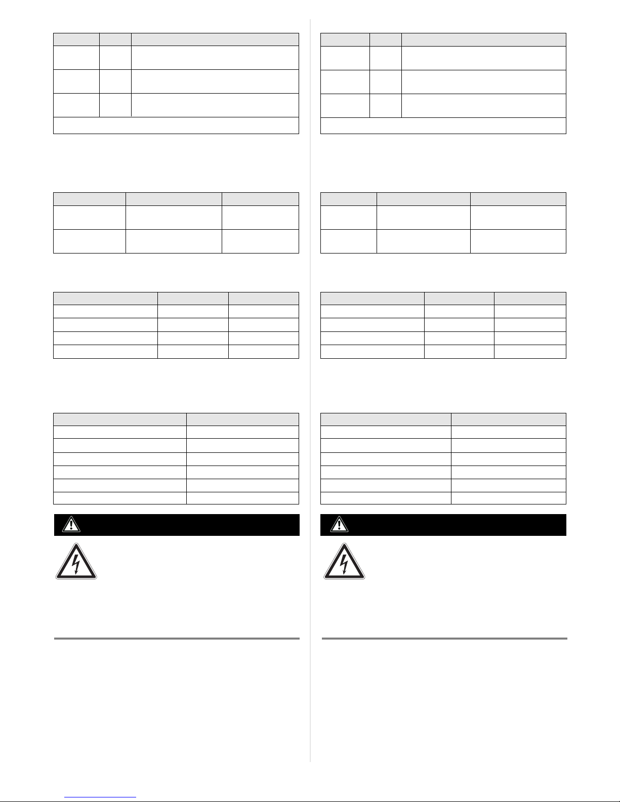
Artikel-Nr. Beschreibung Ansicht
Part No. Description Design
Betriebsumgebungstemperaturbereich 0 ... +40 °C/Operating ambient temperature range 0 to +40 °C (+32 to +104 °F)
2043413 Verlängerungsleitung für CLV42x ... 65x, 3 m, geschirmt, mit 15-pol. D-Sub-HD-Stecker und -Buchse
Extension cable for CLV42x to 65x, 3 m (9.84 ft), shielded, with 15-pin D-Sub HD plug and socket
4038847 IP-65-Dichtung zur Anwendung zwischen Sensor-Anschlussleitung und Verlängerungsleitung
IP 65 gasket for use between sensor connection cable and extension cable
2027046 Anschlussleitung für CLV480, CLV/X490 ohne Heizung, 3 m, geschirmt, mit Steckerhaube (IP 65)
und 15-pol. D-Sub-HD-Stecker für CDB620
Connection cable for CLV480, CLV/X490 without heater, 3 m (9.84 ft), shielded, with connector
cover and 15-pin D-Sub HD plug for CDB620
2030023 Wie Nr. 2027046, jedoch zusätzl. mit Parameterspeicher für CLV480, CLV/X490 in der Steckerhaube Wie oben/see above
As no. 2027046, but additionally with param. memory for CLV480, CLV/X490 in the connector cover
2014054 RS-232-Datenleitung (SICK Nullmodemleitung), 3 m, geschirmt, mit 2 x 9-pol. D-Sub-Buchse
RS 232 data cable (SICK null modem cable), 3 m (9.84 ft), shielded, with 2 x 9-pin D-Sub socket
6027048 UNITRON-CAN-Leitung, 2 x 2 x 0,5 mm2, geschirmt, Meterware –
UNITRON CAN cable, 2 x 2 x 0.5 mm2 (AWG 20), shielded, bought to size
Betriebsumgebungstemperaturbereich –35 ... +40 °C/Operating ambient temperature range –35 to +40 °C (–31 to +104 °F)
1042259 CMC600-101 zur Speicherung der Sensor-Parameter außerhalb des ID-Sensors, erweiterter Temperatur-
bereich
CMC600-101S02 saving the sensor parameters outside of the ID sensor, extended temperature range
2033126 Kälteresistente Anschlussleitung (max. –35 °C) für CLV480, CLV/X490 mit integrierter Heizung, 10 m,
Steckerhaube (IP 65) mit Parameterspeicher, mit 15-pol. D-Sub-HD-Stecker für CDB620 sowie Leitung
mit offenem Ende (Stromversorgung), schleppkettentauglich.
Cold-resistent cable (max. –35 °C (–31 °F)) for connecting the CLV480, CLV/X490 with integrated
heater, 10 m (32.8 ft), connector cover (IP 65) with parameter memory, with 15-pin D-Sub HD
connector for CDB620 as well as a cable with open end (power supply), suitable for track chain use
SICK AG · Waldkirch · Germany
For local sales offices see www.sick.com
8. Fehlersuche
Störung
Nach Anlegen der Versorgungsspannung U
IN
leuchtet die LED
„Power“ (UIN*) nicht
Signale des angeschlossenen
Lesetakt-Sensors bleiben
wirkungslos
Nach Anschluss des PCs an
den Stecker „AUX“ kein
Zugriff auf den Sensor mit
Software CLV-Setup/SOPAS-ET
Abhilfe
Schalter S 1 (Power) in Position
„ON“ bringen
Lesetakt-Sensor gemäß CLV-
Connect anschließen
Stellung des Schalters S 3 prüfen
(SGND–GND)
Mit Software CLV-Setup/SOPAS-ET
die Quelle des Lesetakts im Sensor
auf „Sensor 1“ einstellen. Download
zum Sensor!
Wenn kein CMC600 gesteckt,
Schalter S 4 in Pos. „NO“ bringen
Mit Hilfe der Funktion
„AutoBaudDetect“ in CLV-Setup die
Kommunikationsparameter des PC
automatisch wählen
8. Troubleshoooting
Remedy
Set switch S 1 (Power) to “ON”
Connect reading pulse sensor in
accordance with CLV-Connect
Check switch S 3 (SGND–GND)
Using CLV-Setup/SOPAS-ET
software, set the reading pulse
source on the sensor to “Sensor 1”
Perform a download to the sensor.
If no CMC600 is connected, set
switch S 4 to “NO”
Using the “AutoBaudDetect”
function in “CLV-Setup”, configure
the PC communication parameters
automatically
Malfunction
“Power” LED (UIN*) does not
light up when power supply U
IN
is connected
Signals from connected reading
pulse sensor have no effect
Cannot access sensor with
CLV-Setup/SOPAS-ET software
after connecting the PC to the
"AUX" plug
 Loading...