

Page 1
C4000 Select
Safety Light Curtain
OPERATING INSTRUCTIONS
GB
Page 2

Operating Instructions
C4000 Select
This document is protected by the law of copyright, whereby all rights established therein remain with the company SICK AG. Reproduction of this document or parts of this document is only permissible within the limits of the
legal determination of Copyright Law. Alteration or abridgement of the document is not permitted without the
explicit written approval of the company SICK AG.
2 © SICK AG • Industrial Safety Systems • Germany • All rights reserved 8012247/RI61/2007-11-30
Page 3

Operating Instructions
C4000 Select
List of contents
List of contents
1 About this document......................................................................................................... 6
1.1 Function of this document....................................................................................6
.2 Target group ..........................................................................................................6
1
1.3 Scope ..................................................................................................................... 6
1.4 Depth of information............................................................................................. 6
1.5 Abbreviations.........................................................................................................7
1.6 Symbols used ........................................................................................................7
2 On safety.............................................................................................................................9
2.1 Qualified safety personnel....................................................................................9
2.2 Applications of the device.....................................................................................9
2.3 Correct use ..........................................................................................................10
2.4 General safety notes and protective measures ................................................10
2.5 Protection of the environment............................................................................11
3 Product description.........................................................................................................12
3.1 Special features ..................................................................................................12
3.2 Operating principle of the device .......................................................................12
3.2.1 C4000 Select components...............................................................12
3.2.2 The light curtain principle .................................................................13
3.2.3 Device variants..................................................................................13
3.2.4 Standalone and cascaded systems.................................................13
3.3 Examples of range of use ...................................................................................17
3.4 Status indicators and C4000 Select message center......................................18
3.4.1 Message center of the C4000 Select sender unit ..........................18
3.4.2 Message center of the C4000 Select receiver unit ........................19
3.4.3 Optional integrated LED....................................................................20
4 Configuration ...................................................................................................................21
4.1 Extended I/O........................................................................................................22
4.2 Beam coding........................................................................................................23
4.3 Scanning range ...................................................................................................25
4.4 Floating blanking.................................................................................................27
5 Installation and mounting ..............................................................................................29
5.1 Determining the minimum safety distance .......................................................29
5.1.1 Minimum safety distance to the hazardous area............................29
5.1.2 Hazard approach...............................................................................30
5.1.3 Minimum safety distance according to ANSI/CSA standards
and OSHA regulations.......................................................................31
5.1.4 Minimum safety distance according to EN 999 and EN 294.........32
5.1.5 Minimum distance to reflective surfaces ........................................33
5.2 Steps for mounting the device ...........................................................................34
5.2.1 Mounting with swivel mount bracket...............................................36
5.2.2 Mounting with side bracket..............................................................38
5.2.3 Mounting with rigid mounting bracket.............................................40
5.3 Laser alignment ..................................................................................................41
8012247/RI61/2007-11-30 © SICK AG • Industrial Safety Systems • Germany • All rights reserved 3
Page 4

List of contents
6 Electrical installation .....................................................................................................43
6.1 Bottom end cap with system connection M12×5 male .................................. 44
6.2 Bottom end cap with system connection M12×5 male and extended
I/O connection M12×5 female ......................................................................... 44
6.3 Top end cap with extended I/O M12×5 female connection ........................... 46
7 Commissioning................................................................................................................ 47
7.1 Display sequence during power-up....................................................................47
7.2 Aligning sender and receiver..............................................................................47
7.3 Test notes............................................................................................................48
7.3.1 Tests before the first commissioning .............................................. 48
7.3.2 Regular inspection of the protective device by qualified
safety personnel ...............................................................................48
7.3.3 Daily functional checks of the protective device ............................ 49
8 Configuration ................................................................................................................... 50
9 Care and maintenance ................................................................................................... 51
10 Fault diagnosis ................................................................................................................ 52
10.1 What to do in case of faults ............................................................................... 52
10.2 SICK Support....................................................................................................... 52
10.3 Error displays of the diagnostics LEDs.............................................................. 52
10.4 Error displays of the 7@segment display ............................................................ 54
Operating Instructions
C4000 Select
11 Technical specifications ................................................................................................ 55
11.1 Data sheet........................................................................................................... 55
11.2 Response time.................................................................................................... 58
11.2.1 Calculating the host/standalone response time ............................ 58
11.2.2 Calculating the guest 1 response time............................................59
11.2.3 Calculating the guest 2 response time............................................60
11.2.4 Response time calculation examples.............................................. 60
11.3 Table of weights.................................................................................................. 63
11.3.1 C4000 Select.................................................................................... 63
11.3.2 Deflector mirrors PNS75 and PNS125............................................63
11.4 Dimensional drawings........................................................................................ 64
11.4.1 C4000 Select receiver (all variants)................................................ 64
11.4.2 C4000 Select sender (all variants).................................................. 65
11.4.3 Swivel mount bracket....................................................................... 66
11.4.4 Side mount bracket .......................................................................... 66
11.4.5 Standard L-type mounting brackets ................................................ 67
11.4.6 Deflector mirror PNS75.................................................................... 68
11.4.7 Deflector mirror PNS125..................................................................69
4 © SICK AG • Industrial Safety Systems • Germany • All rights reserved 8012247/RI61/2007-11-30
Page 5

Operating Instructions
C4000 Select
List of contents
12 Ordering information.......................................................................................................70
12.1 Delivery ................................................................................................................70
12.2 C4000 Select without extension connection.....................................................70
12.3 C4000 Select with integrated LED status indicator..........................................71
12.4 C4000 Select with top end cap extension connection .....................................71
12.5 C4000 Select with bottom end cap system and extension connections.........72
12.6 C4000 Select with bottom end cap system/extension connections and
integrated LED status indicator..........................................................................72
12.7 C4000 Select with bottom extension connection (receiver only).....................73
2.8 C4000 Select with bottom extension connection and integrated LED
1
status indicator (receiver only)...........................................................................73
12.9 Additional front screen (weld spark guard) .......................................................74
12.10 Deflector mirror...................................................................................................74
12.10.1 Deflector mirror PNS75 for protective field width 0 … 12 m
(total)..................................................................................................74
12.10.2 Deflector mirror PNS125 for protective field width
4 … 18.5 m (total) .............................................................................74
12.11 Accessories..........................................................................................................75
13 Annex ................................................................................................................................77
13.1 EC declaration of conformity ..............................................................................77
13.2 Checklist for the manufacturer ..........................................................................78
13.3 List of tables........................................................................................................79
13.4 List of illustrations...............................................................................................80
8012247/RI61/2007-11-30 © SICK AG • Industrial Safety Systems • Germany • All rights reserved 5
Page 6

Chapter 1 Operating Instructions
About this document
C4000 Select
1 About this document
Please read this chapter carefully before working with this documentation and the C4000
Select.
1.1 Function of this document
These operating instructions are designed to address the technical personnel of the
machine manufacturer or the machine operator in regards to safe mounting, installation,
configuration, electrical installation, commissioning, operation and maintenance of the
C4000 Select safety light curtain.
These operating instructions do not provide instructions for operating machines on which
the safety light curtain is, or will be, integrated. Information on this is to be found in the
appropriate operating instructions of the machine.
1.2 Target group
These operating instructions are addressed to planning engineers, developers and the
operators of plants and systems which are to be protected by one or several C4000 Select
safety light curtains. It also addresses persons who integrate the C4000 Select into a ma-
chine, initialize its use, or who are in charge of servicing and maintaining the device.
Note
1.3 Scope
These operating instructions apply to the C4000 Select safety light curtain with one of the
following entries on the type label in the field Operating Instructions:
8012198
8012198 / RI61
This document is part of SICK part number 8012198 (operating instructions “C4000
Select” in all available languages).
1.4 Depth of information
These operating instructions contain information on:
installation and mounting
electrical installation
commissioning and configuration
care and maintenance
of the C4000 Select safety light curtain.
Planning and using protective devices such as the C4000 Select also require specific tech-
nical skills which are not detailed in this documentation.
When operating the C4000 Select, the national, local and statutory rules and regulations
must be observed.
General information on health and safety at work and accident prevention using opto-elec-
tronic protective devices can be found in the brochure “Safe Machines with opto-electronic
protective devices” from SICK.
fault, error diagnosis and
troubleshooting
part numbers
conformity and approval
6 © SICK AG • Industrial Safety Systems • Germany • All rights reserved 8012247/RI61/2007-11-30
Page 7

Operating Instructions Chapter 1
C4000 Select
About this document
Note
ESPE
OSSD
PF
PL
SIL
We also refer you to the SICK homepage on the Internet at
www.sick.com
Here you will find information on:
sample applications
a list of frequently asked questions about the C4000 Select
these operating instructions in different languages for viewing and printing
certificates on the prototype test, the EC declaration of conformity and other documents
1.5 Abbreviations
Electro-sensitive protective equipment (e.g. C4000 Select)
Output signal switching device
The probability of failure per hour in accordance with the functional safety testing
H
requirements outlined in IEC 61508
Performance level in accordance with EN ISO 13849@1:2006
Safety integrity level in accordance with IEC 61508/IEC 62061
1.6 Symbols used
Recommendation
Note
Red, Red, Off
Take action …
WARNING
Recommendations are designed to give you some assistance in your decision-making
process with respect to a certain function or a technical measure.
Refer to notes for special features of the device.
Display indicators show the status of the 7@segment display of sender or receiver:
Constant indication of characters, e.g. 2
When using an inverted mounting of the C4000 Select, you must take into account that
the information presented by the 7-segment display will also be inverted.
LED symbols describe the state of a diagnostics LED. Examples:
Red The red LED is illuminated constantly.
Red The red LED is flashing.
Off The LED is off.
Instructions for taking action are shown by an arrow. Read carefully and follow the instruc-
tions for action.
Warning!
A warning indicates an actual or potential risk or health hazard. They are designed to help
you to prevent accidents.
Read carefully and follow the warnings!
Sender and receiver
In drawings and diagrams, the symbol denotes the sender and the symbol denotes
the receiver.
8012247/RI61/2007-11-30 © SICK AG • Industrial Safety Systems • Germany • All rights reserved 7
Page 8

Chapter 1 Operating Instructions
About this document
C4000 Select
The term “dangerous state”
The dangerous state (standard term) of the machine is always shown in the drawings and
iagrams of this document as the movement of a machine part. In practical operation,
d
there may be a number of different dangerous states:
machine movements
electrical conductors
visible or invisible radiation
a combination of several risks and hazards
8 © SICK AG • Industrial Safety Systems • Germany • All rights reserved 8012247/RI61/2007-11-30
Page 9

Operating Instructions Chapter 2
C4000 Select
On safety
2 On safety
This chapter deals with your own safety and the safety of the equipment operators.
Please read this chapter carefully before working with the C4000 Select or with the
machine protected by the C4000 Select.
2.1 Qualified safety personnel
The C4000 Select safety light curtain must be installed, connected, commissioned and
serviced only by qualified safety personnel. Qualified safety personnel are defined as
persons who …
due to their specialist training and experience have adequate knowledge of the power-
driven equipment to be checked
and
who have been instructed by the responsible machine operator in the operation of the
machine and the current valid safety guidelines
and
are sufficiently familiar with the applicable official health and safety regulations,
directives and generally recognized engineering practice (e.g. DIN standards, VDE
stipulations, engineering regulations from other EC member states) that they can
assess the work safety aspects of the power-driven equipment
and
who have access to these operating instructions and who have read and understood
them.
As a rule these are qualified safety personnel from the ESPE manufacturer or also those
persons who have been appropriately trained at the ESPE manufacturer, are primarily
involved in checking ESPE and are allocated the task by the organization operating the
ESPE.
2.2 Applications of the device
The C4000 Select safety light curtain is an electro-sensitive protective equipment (ESPE)
rated to:
type 4 in accordance with IEC 61496@1 and @2
SIL 3 in accordance with IEC 61508 and IEC 62061
category 4 in accordance with EN 954@1:1997
performance level “e” in accordance with EN ISO 13849@1:2006
The physical resolution of the C4000 Select is 30 mm with a maximum protective field
width of up to 21 m and available protective field heights from 300 up to 1800 mm. Configurable parameters are set using DIP switches.
The device is suitable for:
hazardous point protection (hand protection)
hazardous area protection
access protection
8012247/RI61/2007-11-30 © SICK AG • Industrial Safety Systems • Germany • All rights reserved 9
Page 10

Chapter 2 Operating Instructions
WARNING
On safety
C4000 Select
Access to the hazardous point must be allowed only through the protective field. The
lant/system is not allowed to start as long as personnel are within the hazardous area.
p
Refer to chapter 3.3 “Examples of range of use” on page 17 for an illustration of the
protection modes.
Only use the safety light curtain as an indirect protective measure!
An opto-electronic protective device provides indirect protection, e.g., by switching off the
power at the source of the hazard. It cannot provide protection from parts thrown out, nor
from emitted radiation. Transparent objects are not detected.
Depending on the application, mechanical protection devices may be required in addition
to the safety light curtain.
Note
WARNING
The C4000 Select safety light curtain operates as a standalone system, comprising a sender and receiver, or in combination with other extended C4000 Select systems, SICK S300
or S3000 safety laser scanners. This means that the protective field can be adapted to
suit individual safety requirements.
2.3 Correct use
The C4000 Select safety light curtain must be used only as defined in section 2.2 “Applica-
tions of the device”. It must be used only by qualified safety personnel and only on the
machine where it has been installed and initialized by qualified safety personnel in
accordance with these operating instructions.
If the device is used for any other purposes or modified in any way—also during mounting
and installation—any warranty claim against SICK AG and its subsidiary companies shall
become void.
2.4 General safety notes and protective measures
Safety notes
Please observe the following procedures in order to ensure the correct and safe use of the
safety light curtain C4000 Select.
The national/international rules and regulations apply to the installation, use and
periodic technical inspections of the safety light curtain, in particular:
– Machinery Directive 98/37/EEC
– Equipment Usage Directive 89/655/EEC
– the work safety regulations/safety rules
– other relevant health and safety regulations
Manufacturers and operators of the machine with which the safety light curtain is used
are responsible for obtaining and observing all applicable safety regulations and rules.
The notices, in particular the test regulations (see “Test notes” on page 48) of these
operating instructions (e.g. on use, mounting, installation or integration into the existing
machine controller) must be observed.
Changes to the configuration of the devices can degrade the protective function. After
every change to the configuration you must therefore reverify and validate the effective-
ness of the protective device (e.g. C4000 Select).
The person who makes the change is also responsible for the correct protective function
of the device.
10 © SICK AG • Industrial Safety Systems • Germany • All rights reserved 8012247/RI61/2007-11-30
Page 11

Operating Instructions Chapter 2
C4000 Select
On safety
The tests must be carried out by authorized qualified safety personnel and must be re-
orded and documented to ensure that the tests can be reconstructed and retraced at
c
any time.
The operating instructions must be made available to the operator of the machine
where the C4000 Select safety light curtain is installed. The machine operator is to be
instructed in the use of the device by qualified safety personnel and must be instructed
to read the operating instructions.
The external voltage supply of the device must be capable of buffering brief mains vol-
tage failures of 20 ms as specified in EN 60204@1. Suitable power supplies are available as accessories from SICK (i.e. model PS50W@24V, SICK part number 7028789 or
PS95W@24V, SICK part number 7028790).
2.5 Protection of the environment
The C4000 Select safety light curtain has been designed to minimize environmental
impact. It uses only a minimum of power and natural resources.
At work, always act in an environmentally responsible manner. For this reason please note
the following information on disposal.
Notes
Disposal
Always dispose of unserviceable or irreparable devices in compliance with
local/national rules and regulations with respect to waste disposal.
We would be pleased to be of assistance on the disposal of this device. Contact your
local SICK representative.
The disposal of Instapak® foam inserts included in the C4000 Select packaging is com-
pletely compatible with waste-to-energy facilities. Instapak® foam has high energy content similar to that of coal. Instapak® foam can actually be used to aid in the process-
ing of other less combustible materials. The process leaves less than one-percent ash
and is completely free of any heavy metals. Instapak® foam also has a recycling pro-
gram available to help companies meet their recycling needs. Instapak® foam may be
returned to any one of more than twenty-five worldwide locations. Refer on the internet
to http://www.instapak.com/ for additional information.
8012247/RI61/2007-11-30 © SICK AG • Industrial Safety Systems • Germany • All rights reserved 11
Page 12
Chapter 3 Operating Instructions
Fig.1:
Components of the
Host without extension
guest
guest
Product description
C4000 Select
3 Product description
This chapter provides information on the special features and properties of the C4000
Select safety light curtain. It describes the construction and the operating principle of the
device, in particular the different operating modes.
Please read this chapter before mounting, installing and commissioning the device.
3.1 Special features
The C4000 Select supports the following special features:
integrated laser and alignment bar graph
configuration via DIP switches
simple diagnostic codes
an optional LED status indicator
cascading additional C4000 Select system(s) or a single S300/S3000 safety laser
scanner
2 beam codes possible in addition to non-coded operation
status display with 7@segment display
one or two beam floating blanking
C4000 Select
3.2 Operating principle of the device
3.2.1 C4000 Select components
connection or — in case
1 connected — with
extension connection
Optional: 1. Guest system
without extension
connection or — in case
2 connected — with
extension connection
Optional: 2. Guest system
with or without extension
connection
12 © SICK AG • Industrial Safety Systems • Germany • All rights reserved 8012247/RI61/2007-11-30
Please refer to chapter 11 “Technical specifications” on page 55 for the data sheet.
Please refer to pages 64ff. for the dimensional drawings.
Page 13

Operating Instructions Chapter 3
C4000 Select
Product description
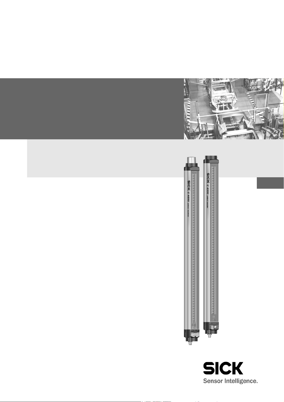
3.2.2 The light curtain principle
The C4000 Select safety light curtain consists of a sender and a receiver (Fig. 1). Between
these two units is the protective field, defined by a protective field height and a protective
field width.
The construction height determines the height of the protective field of the appropriate
system. For the exact protective field height, please see Tab. 40ff. in chapter 11.4
“Dimensional drawings” on page 64.
The width of the protective field is derived from the dimension of the light path between
sender and receiver and must satisfy the specification requirements for the protective field
(see “Technical specifications” on page 55).
Sender and receiver automatically synchronize themselves optically. An electrical connection between both components is not required.
The C4000 Select is modular in construction. All optical and electronic components and
assemblies are housed in a slim and torsionally rigid housing.
3.2.3 Device variants
The C4000 Select sender and receiver devices support several end cap configurations.
You must decide which end cap is best suited for your application at time of order placement. The bottom end cap supports the system connection and optional extended I/O
functionality. Three top end cap options are available: cover only, with an optional
integrated LED or with an optional extended I/O connection.
There are several variants of the C4000 Select:
without any extension connection (no extended I/O capability)
without any extension connection (no extended I/O capability) with integrated LED on
the top end cap of the receiver unit
with extension connection (supports cascading) located on the bottom end cap with the
system connection
with extension connection (supports cascading) located on the top end cap with a sepa-
rate bottom end cap having the system connection
with extension connection (supports cascading) located on the bottom end cap with the
system connection with integrated LED on the top end cap of the receiver unit
3.2.4 Standalone and cascaded systems
The C4000 Select allows you to coordinate multiple protective devices (e.g. additional
C4000 Select devices or SICK S300/S3000 safety laser scanner) in a single safety
system.
A maximum of three C4000 Select devices can be connected in series as a “cascade”. The
following configurations are possible:
standalone operation of a single C4000 Select system
cascade of a host C4000 Select with a guest C4000 Select
cascade of a host C4000 Select with two guest C4000 Select devices
cascade of a host C4000 Select with a SICK S300/S3000 safety laser scanner
Cascaded devices are connected using the extended I/O connection. The extended I/O
connection may be located either beside the system connection (extended I/O connection
on the bottom end cap) or separate from the system connection (extended I/O connection
on the top end cap).
8012247/RI61/2007-11-30 © SICK AG • Industrial Safety Systems • Germany • All rights reserved 13
Page 14
Chapter 3 Operating Instructions
Fig.2:
C4000 Select
recei-
WARNING
Product description
C4000 Select
The benefits of cascading include:
no additional external circuitry required making connection of additional protective
evices easy to implement
d
the protective field height may differ among the individual C4000 Select devices
a combination of hazardous point (i.e. C4000 Select) and area protection devices (e.g.
ICK S300/S3000 safety laser scanners) can be realized in a single safety system.
S
The following sections describe the different configurations supported by the C4000
Select. For ease of understanding, only the receiver units have been shown in subsequent
figures.
Ensure that you set the Extended I/O DIP switch correctly for your application!
When cascading additional protective devices to the C4000 Select, you must ensure that
the Extended I/O DIP switch has been set to Enabled. Failure to enable the Extended I/O
function in cascaded applications will expose personnel to risk of the associated hazard!
Please refer to chapter 4 “Configuration” on page 21 for additional details regarding
extended I/O DIP switch settings and functionality.
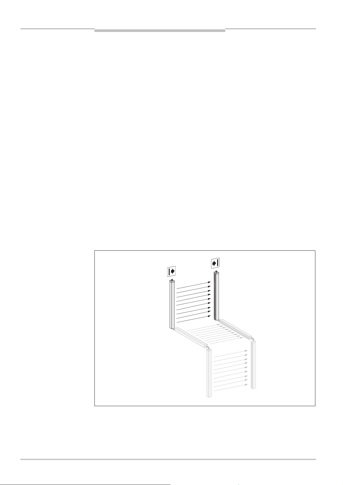
Standalone operation
Standalone operation can be realized with all C4000 Select variants. Regardless of variant, DIP switch configuration can be set for standalone operation (refer to chapter 4 “Con-
figuration” on page 21 for additional information).
vers used in standalone
operation (shown without
extended I/O capability)
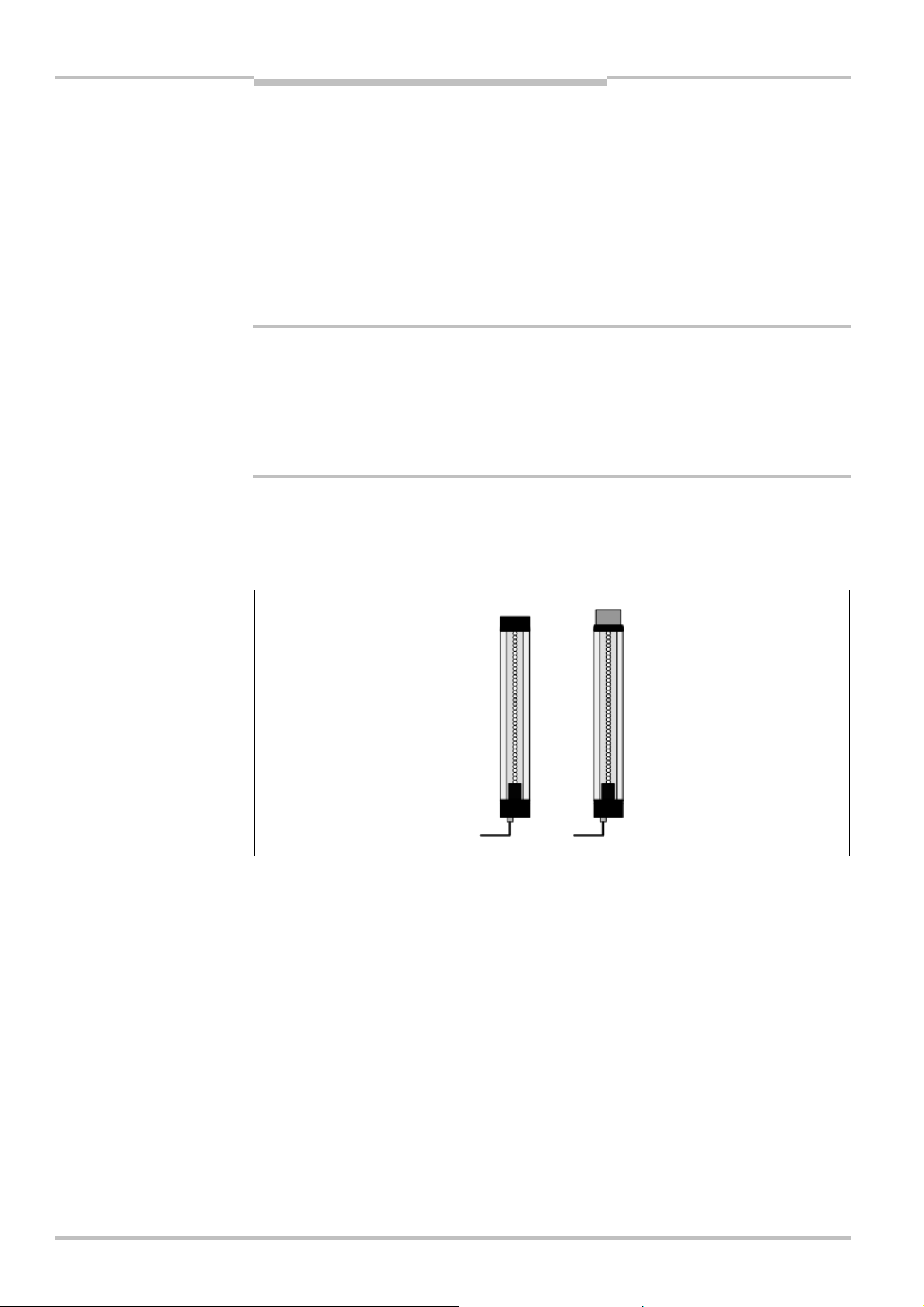
Cascade of multiple C4000 Select systems
The C4000 Select supports the cascade of up to three 1800 mm protective height C4000
Select sender and receiver pairs. This may be realized only when the extended I/O connection is available. When three light curtains are cascaded together, a physical barrier may
be necessary to prevent optical interference between the two light curtains configured with
the same beam code if they are positioned too closely together. Refer to section 4.2
“Beam coding” on page 23 for additional information regarding this requirement.
14 © SICK AG • Industrial Safety Systems • Germany • All rights reserved 8012247/RI61/2007-11-30
Page 15
Operating Instructions Chapter 3
Fig.3:
C4000 Select
recei-
Fig.4:
C4000 Select
recei-
Guest 1
Host
Guest 2
Guest 1
Host
Guest 2
C4000 Select
Product description
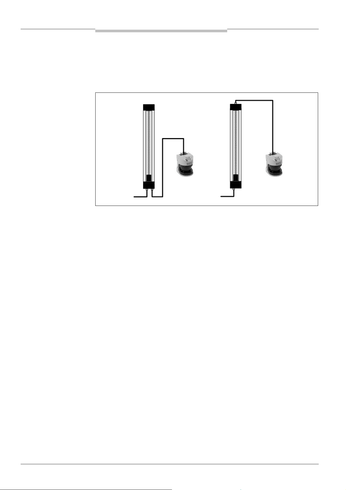
There are two methods of implementing C4000 Select cascades. The first method utilizes
n extended I/O connection located on the top end cap for the first C4000 Select (host)
a
and the second C4000 Select (guest 1). The third C4000 Select (guest 2) utilizes a system
connection only.
vers used in cascade with
extension connection (on top
end cap)
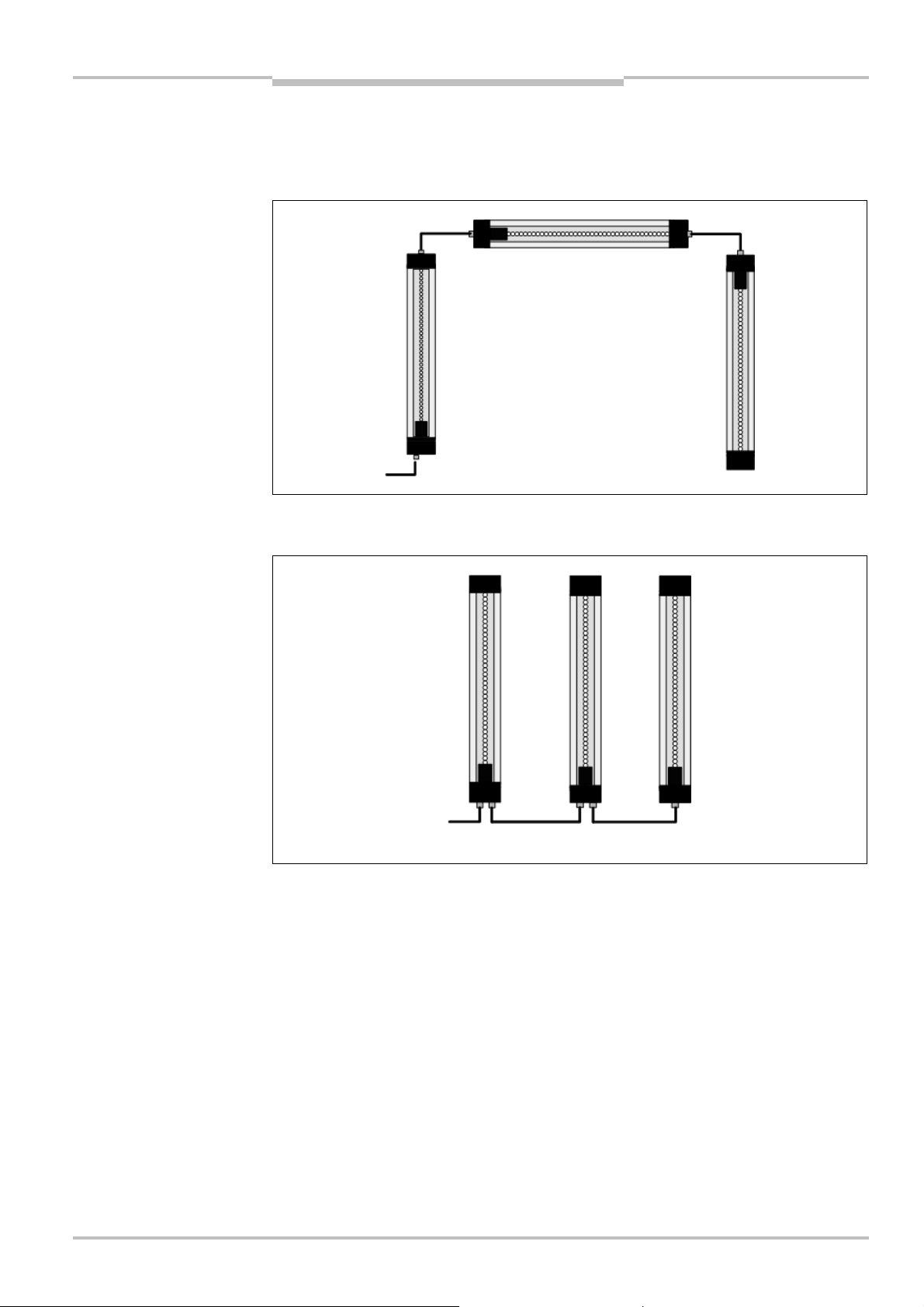
vers used in cascade with
extension connection (on
same end cap as system
connection)
Note
Alternatively, the second method of implementing cascaded C4000 Select devices uses an
extended I/O connection that is located on the same end cap as the system connection.
Sender units cannot be physically connected to receiver units when cascading C4000
Select devices. Always physically connect sender units together when cascading. Always
physcially connect receiver units together when cascading C4000 Select devices.
8012247/RI61/2007-11-30 © SICK AG • Industrial Safety Systems • Germany • All rights reserved 15
Page 16
Chapter 3 Operating Instructions
Fig.5:
C4000 Select
receiver
Product description
C4000 Select
Cascade of C4000 Select and SICK S300/S3000 safety laser scanner
The C4000 Select supports the cascade of a single SICK S300 or S3000 safety laser scan-
er. Connection of the S300 or S3000 occurs on the extended I/O connection to provide
n
both power and connection of safety relevant signals (i.e. safety outputs from the safety
scanner). The extended I/O connection may be located on either the top end cap or with
the system connection on the bottom end cap of the C4000 Select.
with extended I/O connection
(shown on top end cap and
with system connection) used
to cascade a SICK S3000
safety laser scanner
16 © SICK AG • Industrial Safety Systems • Germany • All rights reserved 8012247/RI61/2007-11-30
Page 17
Operating Instructions Chapter 3
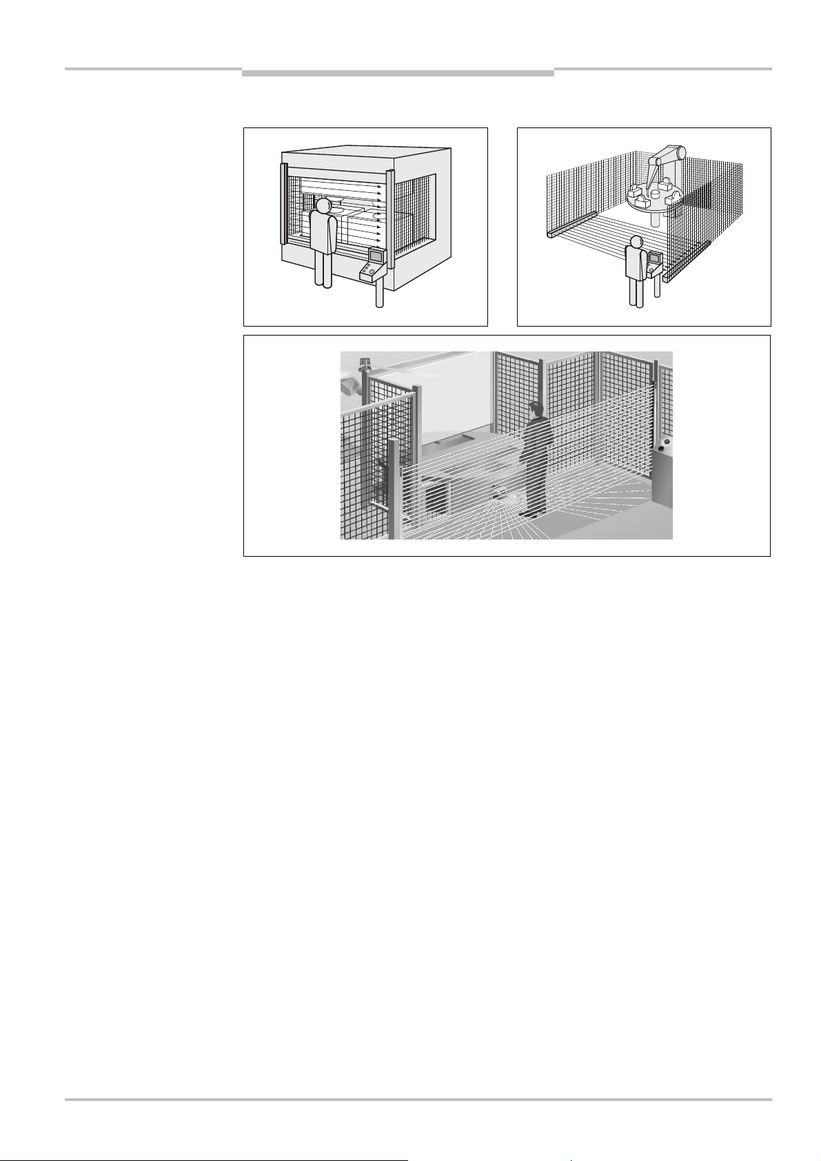
Fig.6:
Hazardous point pro-
Fig.8:
Access protection
C4000 Select
Product description
3.3 Examples of range of use
tection using a C4000 Select
safety light curtain
(left)
Fig. 7: Hazardous area protection using a C4000 Select
safety light curtain
(right)
using a C4000 Select safety
light curtain cascaded with
an S3000 safety laser
scanner
The C4000 Select safety light curtain operates correctly as a protective device only if the
following conditions are met:
The control of the machine must be electrical.
The dangerous state of the machine must be transferable at any time into a safe state.
Sender and receiver unit must be mounted so that objects penetrating the hazardous
area are safely identified by the C4000 Select.
An external reset/restart function (e.g. button) must be fitted outside the hazardous
area such that it cannot be operated by a person working inside the hazardous area.
When operating the reset button, the operator must have full visual command of the
hazardous area.
The statutory and local rules and regulations must be observed when installing and
using the device.
8012247/RI61/2007-11-30 © SICK AG • Industrial Safety Systems • Germany • All rights reserved 17
Page 18

Chapter 3 Operating Instructions
Fig.9:
Message center for
Tab.1:
C4000 Select
LED
Laser alignment
Product description
C4000 Select
3.4 Status indicators and C4000 Select message center
he C4000 Select provides simple operational status information using LED indicators and
T
a 7@segment display.
3.4.1 Message center of the C4000 Select sender unit
The message center for the C4000 Select sender unit has two LEDs that provide operatio-
nal status as shown in the figure below:
C4000 Select sender unit
indication on sender
LED Name Display Meaning
Yellow Supply voltage OK
POWER
Off Check the power to the sender unit
Red The sender unit has detected an internal error. Replace sender
REPLACE
unit.
Off Internal self-test completed successfully or power is off.
18 © SICK AG • Industrial Safety Systems • Germany • All rights reserved 8012247/RI61/2007-11-30
Page 19
Operating Instructions Chapter 3
Fig.10:
Message center for
Tab.2:
C4000 Select
recei-
C4000 Select
Product description
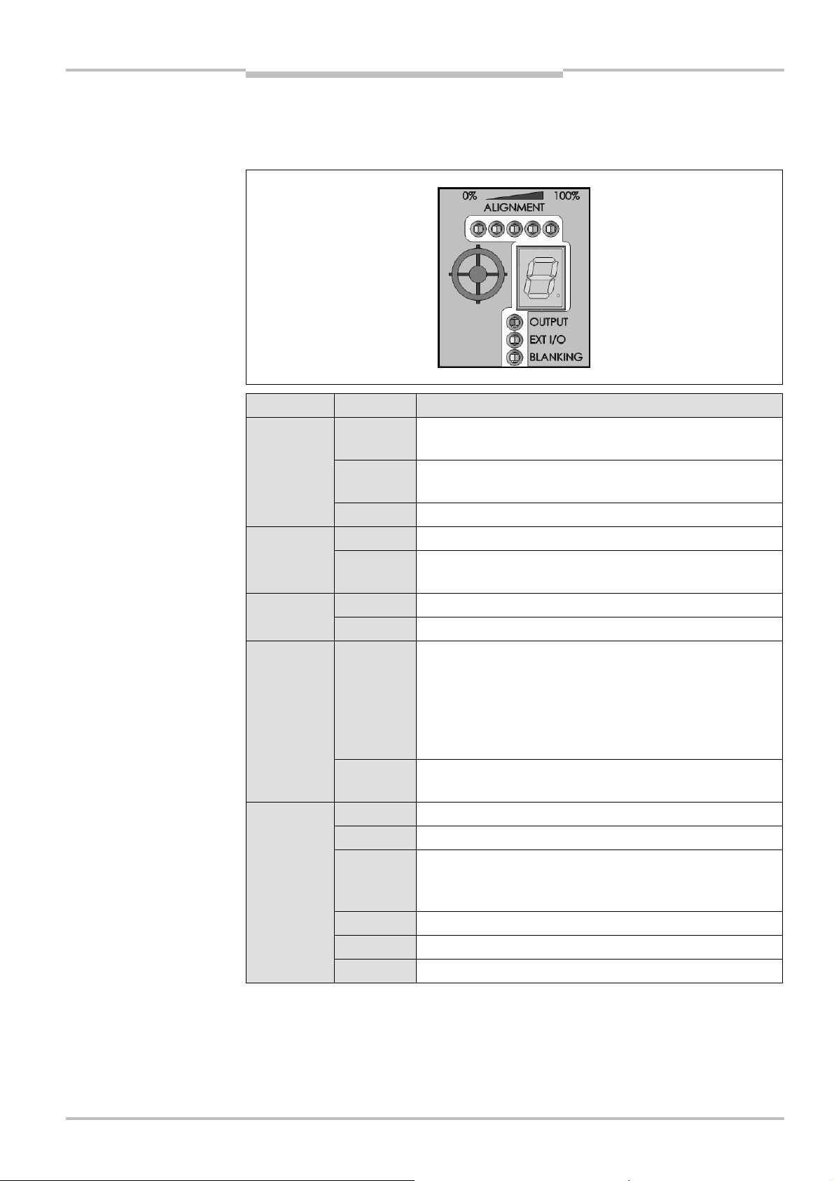
3.4.2 Message center of the C4000 Select receiver unit
The message center for the C4000 Select receiver unit consists of several LED groups and
a 7@segment LED display that provides operational status as shown in the figure below:
C4000 Select receiver unit
ver LED display indication
LED Name Display Meaning
OUTPUT
Green Output signal switching devices (OSSD)/safety outputs
are ON
Red Output signal switching devices (OSSD)/safety outputs
are OFF
Off No power is currently supplied to the receiver unit
Red Extended I/O safety inputs are Inactive (Low) i.e. OFFEXT I/O
Off Extended I/O safety inputs are Active (High) i.e. ON or
Extended I/O has been disabled
Yellow Blanking is activeBLANKING
Off Blanking is inactive
ALIGNMENT
LEDs
Yellow Indicates that one or more beams are aligned between sen-
der and receiver units. The first LED will be Yellow when
one of the synchronization beams has been aligned. When
all five (5) LEDs are Yellow, this indicates all beams are
aligned between sender and receiver units, but there is a
weak signal.
Green When all five (5) LEDs are Green, this indicates that all
beams are aligned between sender and receiver units.
8012247/RI61/2007-11-30 © SICK AG • Industrial Safety Systems • Germany • All rights reserved 19
7?segment
display
An internal error has been detected. Replace receiver unit.
Check DIP switch settings
Optical signals have been detected from multiple sender
units. Change beam code of this C4000 Select
sender/receiver pair.
Check power supply voltage
Check system wiring for errors
Check extended I/O wiring for errors
Page 20

Chapter 3 Operating Instructions
Tab.3:
C4000 Select
inte
gra-
Product description
C4000 Select
3.4.3 Optional integrated LED
When the receiver unit includes the optional integrated LED, the following LED states are
defined:
ted LED display indication
Integrated LED Meaning
Red Output signal switching devices (OSSD)/safety outputs are OFF
Green Output signal switching devices (OSSD)/safety outputs are ON
Off No power is currently supplied to the receiver unit
20 © SICK AG • Industrial Safety Systems • Germany • All rights reserved 8012247/RI61/2007-11-30
Page 21
Operating Instructions Chapter 4
Fig.11:
C4000 Select
sender
Tab.4:
C4000 Select
sender
Fig.12:
C4000 Select
recei-
Tab.5:
C4000 Select
recei-
1 = Beam code 1 select
1=High range select
1=Beam code 1 select
5=Two b
eam floating blanking select
ON position
OFF position
C4000 Select
Configuration
4 Configuration
The C4000 Select supports several advanced functions which are configured using DIP
switches. Included in these advanced functions are beam coding, extended I/O capability
and floating blanking. The DIP switches used for configuration are located under the
lastic cover in the system connection end cap.
p
You must ensure electrostatic discharge does not occur when handling the C4000
WARNING
unit DIP switch
Select!
Before handling the C4000 Select, you must ensure that any electrostatic charge is dis-
charged. An electrostatic discharge that occurs on the C4000 Select may cause damage
to the electronic boards.
The following figure and table describe the C4000 Select sender unit DIP switch settings:
2 = Beam code 2 select
unit DIP switch settings
ver unit DIP switches
ver unit DIP switch settings
for high range
Beam code 1 Beam code 2 Description
OFF OFF No beam coding (uncoded)
ON OFF Beam code 1 enabled
OFF ON Beam code 2 enabled
ON ON No beam coding (uncoded)
Additional information regarding the scanning range can be found in section 4.2 “Beam
coding” on page 23.
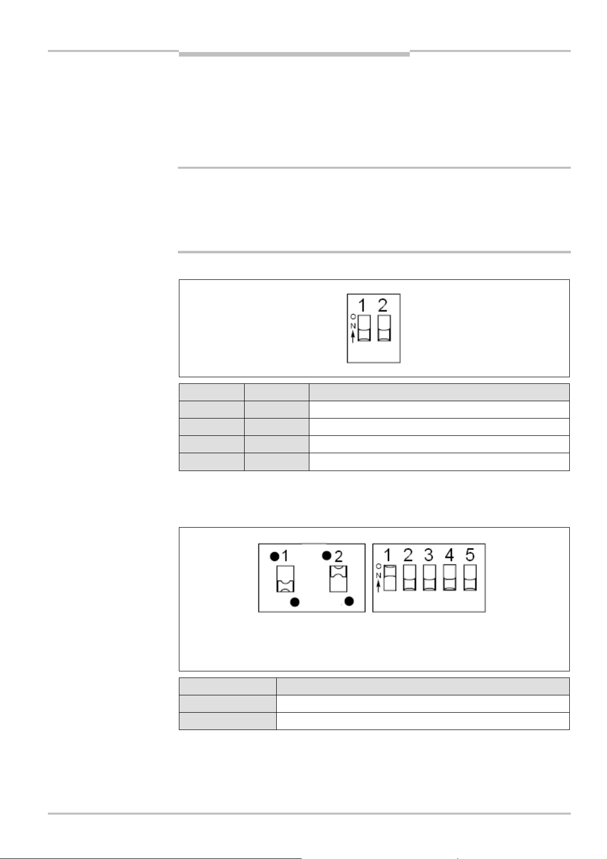
The following figure and table describe the C4000 Select receiver unit DIP switch settings:
2 = Extended I/O enable
High range select Description
OFF Scanning range set to low range (0…7.5 m)
2 = Beam code 2 select
3 = Floating blanking enable
4 = One beam floating blanking select
8012247/RI61/2007-11-30 © SICK AG • Industrial Safety Systems • Germany • All rights reserved 21
ON Scanning range set to high range (5…21 m)
Additional information regarding the scanning range can be found in section 4.3 “Scanning
range” on page 25.
Page 22
Chapter 4 Operating Instructions
Tab.6:
C4000 Select
recei-
Tab.7:
C4000 Select
recei-
Tab.8:
C4000 Select
recei-
Tab.9:
C4000 Select
exten-
Configuration
C4000 Select
ver unit DIP switch settings
for extended I/O enable
ver unit DIP switch settings
for beam coding
ver unit DIP switch settings
for floating blanking
Extended I/O enable Description
OFF Extended I/O functions are disabled
ON Extended I/O functions are enabled
Additional information regarding the scanning range can be found in section 4.1
“Extended I/O” on page 22.
Beam code 1 Beam code 2 Description
OFF OFF No beam coding (uncoded)
ON OFF Beam code 1 enabled
OFF ON Beam code 2 enabled
ON ON No beam coding (uncoded)
Additional information regarding the scanning range can be found in section 4.2 “Beam
coding” on page 23.
Floating
blanking
enable
One beam
FB select
Two beam
FB select
Description
OFF OFF OFF Floating blanking is disabled
ON ON OFF Floating blanking is enabled for 1 beam blanking
ded I/O system output evaluation of the C4000 Select
host device
ON OFF ON Floating blanking is enabled for 2 beam blanking
All other configurations Invalid configuration will result in a fault condition
Additional information regarding the scanning range can be found in section 4.4 “Floating
blanking” on page 27.
4.1 Extended I/O
Enabling the C4000 Select extended I/O functionality allows the connection (i.e. cascade)
of additional C4000 Select or SICK S300/S3000 safety laser scanners with the C4000
Select. Refer to section 3.2.4 “Standalone and cascaded systems” on page 13 for
additional details regarding C4000 Select cascading options.
When additional devices are cascaded with the C4000 Select, the safety outputs (OSSDs)
of the host C4000 Select represent the logical value of all devices in the cascade.
Extended I/O
DIP switch
setting
Enabled
Extended I/O
safe input 1
1)
0
01
10 0
Extended I/O
safe input 2
00
2)
C4000 Select
protective field
C4000 Select
safety outputs
(OSSDs)
0
22 © SICK AG • Industrial Safety Systems • Germany • All rights reserved 8012247/RI61/2007-11-30
Disabled
1)
E.g. inactive (low); red.
2)
E.g. active (high); green.
11 1
00 1
Aligned and
unblocked
01 0
10 0
11
0
Page 23

Operating Instructions Chapter 4
C4000 Select
WARNING
Configuration
When the extended I/O safety inputs are not at their expected state (e.g. both inputs
should be Active (High) or Inactive (Low)), they are considered “discrepant”. The inputs
ust reach an equivalent value before the internal discrepancy timer expires. Failure to
m
reach an equivalent value before the discrepancy time expires will cause a lock-out
condition to occur.
Electrical-mechanical devices (e.g. emergency stop buttons or safety interlock switches)
must not be connected to the extended I/O.
You must ensure that the Extended I/O DIP switch setting satisfies your safety
application requirements!
When cascading one or more devices with the C4000 Select, you must ensure that the extended I/O DIP switch setting(s) for extended I/O is enabled as required for your applica-
tion. You must also validate that the C4000 Select and all cascaded protective devices
perform in accordance with your risk assessment, risk reduction strategy as well as appli-
cable local, regional and national regulatory requirements.
You must ensure that protective device inputs attached to the inputs of the extended
I/O connection can be read safely!
The inputs (IN1, IN2) of an extended I/O connnection enable the 24 V DC PNP-semicon-
ductor safety outputs from a self-monitoring sensor (e.g. another C4000 Select or an
S300/S3000 safety laser scanner) to be read safely. The sensor connected to the inputs
of the extended I/O connection (e.g. guest C4000 Select or S3000 safety laser scanner)
must …
be self-monitoring and detect any error conditions that may occur with its output signal
switching devices (OSSDs) using test signals. The host C4000 Select filters these test
signals out.
execute a safe shutdown of the switching outputs when any error is detected.
Integrated safety mechanisms ensure detection of possible errors on safety capable inputs
for:
Internal errors on safety capable inputs which prevent the inputs from returning to the
safe state. An internal error on a safety capable input is a failure of the C4000 Select
electrical input circuitry.
Discrepancy of the dual-channel input evaluation
Additional measures must be made to address any external errors that cannot be monitored internally by the C4000 Select. In addition, you must exclude any external errors that
could occur due to selected user configuration parameters.
4.2 Beam coding
If several safety light curtains operate in close proximity to each other, the sender beams
of one system may optically interfere or even align itself with the receiver of another sys-
tem. With code 1 or 2 activated, the receiver can distinguish the beams designated for it
from other beams. The following settings are available: non-coded, code 1 and code 2.
Use different beam codings if the systems are mounted in close proximity!
WARNING
8012247/RI61/2007-11-30 © SICK AG • Industrial Safety Systems • Germany • All rights reserved 23
Systems mounted in close proximity to each other must be operated with different beam
codings (code 1 or code 2). If this precaution is neglected, the system may be impaired in
its protective function by the beams from the neighboring system and so change to the
unsafe state. This would mean that the operator is at risk.
Page 24
Chapter 4 Operating Instructions
Fig.13:
Schematic layout of
Tab.10:
C4000 Select
7>seg-
Fig.14:
Minimum distance
Code 1
Code 2
DaSystem 1
System 2
the beam coding
Configuration
C4000 Select
Notes
ment display on power-up for
beam coding
Beam coding increases the availability of the protected machine. Beam coding also en-
hances the resistance to optical interference such as weld sparks.
Using different beam coding settings will allow one C4000 series sender/receiver pair
to be mounted in close proximity to another C4000 series sender/receiver pair without
optical interference.
Beam coding will increase the response time of the system. This will also change the
required safety distance. Instructions can be found in chapter 5.1 “Determining the
minimum safety distance” on page 29.
In order for the C4000 Select system to operate, both the sender and corresponding
receiver of each C4000 Select system must have the same beam code configuration.
After activating the system, the C4000 Select receiver will briefly display the coding.
7-segment display Description
No beam coding
Beam code 1 active
Beam code 2 active
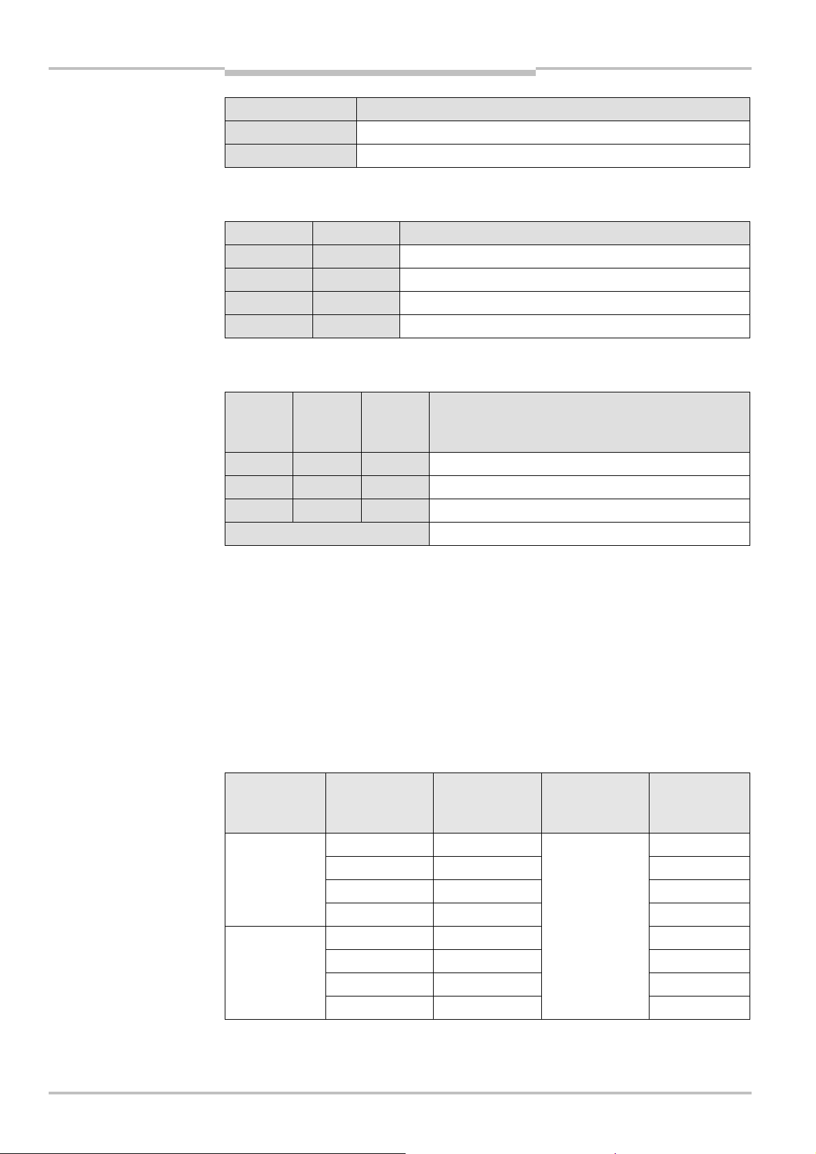
To prevent the possibility of optical interference from C4000 Select devices that have
been configured with the same beam codes (e.g. no coding, beam code 1 or beam code
2), a minimum distance between the two systems must be implemented. The following
figure provides information regarding the minimum distance “a” that must separate the
two C4000 Select systems based on the distance D between the sender of system 1 and
the receiver of system 2.
between C4000 Select systems for systems with the
same beam code configuration
24 © SICK AG • Industrial Safety Systems • Germany • All rights reserved 8012247/RI61/2007-11-30
Page 25
Operating Instructions Chapter 4
Fig.15:
Minimum distance
Tab.11:
Typical scanning
Tab.12:
C4000 Select
7>seg-
C4000 Select
between C4000 Select systems based on same beam
coding configuration
Configuration
Refer to chapter 4 “Configuration” on page 21 for additional details on DIP switch setting
requirements for beam coding.
4.3 Scanning range
WARNING
ranges
ment display on power-up for
scanning range
Notes
Scanning range defines the strength of the C4000 Select protective field beams in order to
allow for longer distances between the C4000 Select sender and receiver devices.
Match the scanning range with the protective field width!
The scanning range of the system (host, guest 1 and guest 2) must be adapted to the protective field width. If the scanning range is set to high range and the light curtains are
mounted below the minimum scanning range value, the safety light curtain may not reliably detect objects within the protective field. This would mean that the operator is at risk.
Two scanning ranges are selectable:
Physical resolution Selectable scanning ranges
0…7.5 m30 mm
5…21 m
7?segment display Description
No symbol Low range (0…7.5 m) selected
High range (5…21 m) selected
If the scanning range is set too low, the safety light curtain may not switch to green.
Tab. 11 shows the guaranteed scanning ranges for the system.
Deflector mirrors are available as accessories (see page 74f.). When used, deflector
mirrors will reduce the effective scanning range based on the number used (see
Tab. 13). When using deflector mirrors, you must configure the safety light curtain for
high scanning range.
8012247/RI61/2007-11-30 © SICK AG • Industrial Safety Systems • Germany • All rights reserved 25
WARNING
Do not use deflector mirrors if the formation of droplets or heavy contamination of the
deflector mirrors is to be expected!
The formation of droplets of heavy contamination can be detrimental to the reflection
behavior. The protective function of the system will be affected and the system will thus
become unsafe. This would mean that the operator is at risk.
Page 26

Chapter 4 Operating Instructions
Tab.13:
Scanning ra
nge
Configuration
C4000 Select
when using 1 or 2 deflector
mirrors
C4000 SelectDeflector mirror
Minimum Typical
1 × PNS75 8 m13 m
2 × PNS75 8 m12 m
1 × PNS125 17 m 18.5 m
2 × PNS125 15.2 m 16.8 m
The information in the table relates to 90° beam deflection per mirror and a protective
field height of 900 mm. If you need more advice on mirror applications, please get in touch
with your local SICK representative.
Refer to chapter 4 “Configuration” on page 21 for additional details on DIP switch setting
requirements for scanning range.
26 © SICK AG • Industrial Safety Systems • Germany • All rights reserved 8012247/RI61/2007-11-30
Page 27

Operating Instructions Chapter 4
Fig.16:
Example of mecha-
C4000 Select
Configuration
4.4 Floating blanking
loating blanking functionality permits the C4000 Select safety outputs (OSSDs) to remain
F
in an active (high) state (e.g. green state) when an object of limited, fixed size is moving in
the protective field of the C4000 Select. The C4000 Select supports one- or two-beam
loating blanking. It is not required that an object be present for the outputs to be active
f
(high) and only one floating blanking field may exist in a single C4000 Select.
When one-beam floating blanking has been enabled, one beam may be blocked in the pro-
tective field of the C4000 Select without causing a stop condition to occur. When twobeam floating blanking is enabled, two contiguous beams may be blocked in the protective
field of the C4000 Select without causing a stop condition to occur. When an object that is
larger than the floating blanking configuration of the C4000 Select, or when more than
one object has been detected in the protective field of the C4000 Select, an immediate
stop condition will occur.
The first beam, normally used for synchronization, may be blanked. An algorithm is integrated into the floating blanking function to allow sparks or other small objects to transit
through the protective field without causing a stop condition to occur.
Configuration of floating blanking is accomplished by using three of the DIP switch positi-
ons. A single switch enables or disables floating blanking, while the other two switches
enable either one- or two-beam floating blanking. All three DIP switches must be in the off
position in order for floating blanking to be turned off. Refer to chapter 4 “Configuration”
on page 21 for additional details on DIP switch setting requirements for floating blanking.
When the C4000 Select is used with one or two additional C4000 Select devices via
connection to the extended I/O connection, floating blanking may be independently
configured on any or all of the devices.
A Yellow LED in each C4000 Select receiver message center indicates when floating
blanking is active.
WARNING
nical protection of floating
blanking
Blanked areas require a separate risk analysis!
A blanked area is in principle a hole in the protective field. Check in detail whether and
where blanking is actually required. You must protect the blanked area in another way, e.g.
mechanically. Otherwise, you must take the blanked area into consideration in the calculation of the safety distance and mount the safety light curtain appropriately.
Blanked area, sides
protected by
mechanical barriers
After modifying the blanking, check the protective field with the test rod. Instructions
can be found in chapter 7.3.3 on page 49.
Floating blanking is not suitable for all applications. Please consult the relevant safety
standards and regulations that apply to your application.
8012247/RI61/2007-11-30 © SICK AG • Industrial Safety Systems • Germany • All rights reserved 27
Page 28

Chapter 4 Operating Instructions
Tab.14:
Effective resolution
Fig.17:
Marking the effective
Configuration
C4000 Select
When floating blanking has been implemented with a C4000 Select device, a hole is pro-
uced in the protective field. With the aid of Tab. 14 you can determine the effective
d
resolution of the safety light curtain at this point and the corresponding minimum object
size that ensures that the C4000 Select safety outputs switch to inactive (low) (i.e. red
state).
for C4000 Select with
floating blanking
resolution on the device label
Physical resolution Size of the blanked
area
Blanked beams
(= reduction)
Effective resolution/
size of the hole
20 mm 1 beam 50 mm30 mm
0 mm 2 beams 70 mm
4
Mark the effective resolution on the information label “Warning: During operation with
Floating blanking …” on the related sender and receiver.
Warning: During operation with “Floating blanking” the safety distance that
corresponds to the modified effective resolution is to be observed.
Reduction Effective resolution/minimum object size
No blanking 30 mm
Floating blanking – 1 beam 50 mm
Floating blanking – 2 beams 70 mm
Mark the effective resolution here
28 © SICK AG • Industrial Safety Systems • Germany • All rights reserved 8012247/RI61/2007-11-30
Page 29

Operating Instructions Chapter 5
C4000 Select
Installation and mounting
5 Installation and mounting
This chapter describes the preparation and completion of the installation of the C4000
Select. The mounting requires two steps:
determining the necessary safety distance
mounting with swivel mount or side bracket, rigid or pivoting mounting bracket
The following steps are necessary after mounting and installation:
completing the electrical connections (chapter 6 “Electrical installation” on page 43)
aligning sender and receiver (chapter 7.2 “Aligning sender and receiver” on page 47)
testing the installation (chapter 7.3.1 “Tests before the first commissioning” on
page 48)
5.1 Determining the minimum safety distance
The C4000 Select must be mounted with an adequate safety distance:
to the hazard or hazardous area
from reflective surfaces
WARNING
Note
WARNING
No protective function without sufficient safety distance!
You must mount the C4000 Select with the correct safety distance to the hazardous
area. Otherwise the safe protection of the C4000 Select system is not provided.
Risk of failure to detect!
Persons who are in the hazardous area but not in the light path between sender and
receiver are not detected by the C4000 Select system. It is therefore to be ensured that
the hazardous area is fully visible and any dangerous state can only be initiated if there
are no personnel in the hazardous area.
The applicable legal and official regulations apply to the use and mounting of the C4000
Select safety light curtain and any associated protective devices. These regulations vary
depending on the application.
5.1.1 Minimum safety distance to the hazardous area
A minimum safety distance must be maintained between the safety light curtain and the
hazardous area. This ensures that the hazardous area can only be reached when the
dangerous state of the machine is completely at an end.
You must ensure that the minimum safety distance requirements are implemented
correctly!
The minimum safety distance is calculated to ensure that personnel cannot reach a hazar-
dous condition before the hazard ceases to exist. You must ensure that the implementation of the safety system(s) (e.g. the protective device, safety interface and associated
actuator(s)) adheres to the requirements of applicable local, regional and national
standards and regulations. Consult applicable standards and regulations for additional
requirements that may pertain to your application.
You must also take preventive measures to ensure that personnel cannot reach over, un-
der, around or through the protective device undetected. Personnel must be detected by
the safety light curtain when approaching the hazard.
8012247/RI61/2007-11-30 © SICK AG • Industrial Safety Systems • Germany • All rights reserved 29
Page 30

Chapter 5 Operating Instructions
Fig.18:
Installation approach
Limit of
Hazardous
Direction of
Floor
DSH
AOPD
Limit of
Hazardous
Direction of
Floor
DSH
AOPD
Limit of
Hazardous
Direction of
Floor
DSH
AOPD
?
Installation and mounting
C4000 Select
The minimum safety distance is defined by several parameters, including:
stopping/run-down time of the machine or system
the stopping/run-down time is shown in the machine documentation or must be
(
measured under worst case conditions.)
response time of the protective device (see chapter 11.2 “Response time” on page 58)
reach or approach speed
resolution of the safety light curtain
other parameters that are stipulated by applicable standards and regulations
5.1.2 Hazard approach
The minimum safety distance changes based on the implementation of the protective
device. Most applications use a perpendicular (e.g. vertical as shown below) mounting of a
safety light curtain. However, it may be necessary to install the safety light curtain in a
horizontal or angular orientation. The following figure provides examples of perpendicular
(vertical), horizontal and angular implementations of a safety light curtain.
considerations for minimum
safety distance calculation
protective
field
penetration
Perpendicular Horizontal
area
protective field
penetration
Angular
protective field
area
area
30 © SICK AG • Industrial Safety Systems • Germany • All rights reserved 8012247/RI61/2007-11-30
penetration
Page 31

Operating Instructions Chapter 5
Tab.15:
Minimum safety
C4000 Select
Installation and mounting
5.1.3 Minimum safety distance according to ANSI/CSA standards and OSHA regulations
The following table summarizes typical calculations of the minimum safety distance.
distance formula summary
per ANSI/CSA standards
Note
Approach Minimum safety distance calculation based on 30 mm object
detection (resolution)
Perpendicular
P = 90º (± 5º)
Horizontal
P = 0º (± 5º)
Angular
5º P 85º
= Hs× (Ts+ Tc+ Tr+ Tbm) + D
D
s
Where D
= Hs× (Ts+ Tc+ Tr+ T
D
s
is 3.08 inches (78.2 mm)
f
p
m
b
) + D
pf
f
p
Where Dpf is 48 inches (1.21 m)
For P 30º, use the perpendicular approach.
P 30º, use the horizontal approach.
For
The minimum safety distance requirement is based on the beam
that is located the closest to the hazard.
This table presents summary information only and additional requirements may apply for
your application. Consult the relevant standards and regulations for additional requirements related to the minimum safety distance calculation.
The following example shows the calculation of the minimum safety distance based on
ANSI B11.19, CAN/CSA Z434 and OSHA 29 CFR 1910.217 for a perpendicular (e.g. verti-
cal) installation of a safety light curtain. Depending on the application and the ambient
conditions, a different calculation may be necessary.
First, calculate D
D
=Hs× (Ts+ Tc+ Tr+ Tbm) + D
s
using the following formula:
s
pf
Where …
D
= The minimum safety distance in inches (or mm) from the hazardous point to the
s
protective device
= A parameter in inches/second or mm/second, derived from data on approach
H
s
speeds of the body or parts of the body.
Often 63 inches/second is used for H
T
= Stopping/run down time of the machine tool measured at the final control
s
.
S
element
= Stopping/run-down time of the control system
T
c
T
= Response time of the entire protective device after light path interruption
r
T
= Additional response time allowed for brake monitor to compensate for wear
bm
D
= Depth of penetration factor. An additional distance added to the overall safety
pf
distance required. The value is based on the intrusion toward the hazardous
point prior to detection by the safety light curtain. The D
for a perpendicular
pf
(vertical) safety light curtain with 30 mm (1.18 in) object sensitivitiy (resolution)
can be approximated based on the following formula from ANSI/RIA R15.06:
(inches) = 3.4 × (object sensitivity – 0.276), but not less than 0.
D
pf
= 3.4 × (1.18 – 0.276) = 3.08 in
Any additional response times that apply to your application must be accounted for in this
calculation.
8012247/RI61/2007-11-30 © SICK AG • Industrial Safety Systems • Germany • All rights reserved 31
Page 32

Chapter 5 Operating Instructions
Tab.16:
Minimum safety
Installation and mounting
C4000 Select
Example
Stopping/run-down time of the machine = 290 ms
esponse time after light path interruption = 30 ms
R
Resolution of the light curtain = 30 mm
T
= 290 ms + 30 ms = 320 ms = 0.32 s
total
D
s
=(Hs× T
total
) + D
pf
= (63 in/s × 0.32 s) + 3.08 in
= 23.25 in (591 mm)
5.1.4 Minimum safety distance according to EN 999 and EN 294
The following table summarizes typical calculations of the minimum safety distance.
distance formula summary
per EN 999 and EN 294
when no floating blanking is
implemented
Approach Minimum safety distance calculation based on 30 mm object
detection (resolution) (mm)
Perpendicular
P = 90º (± 5º)
Ds= 2000 × T + 128
If D
> 500 mm, using the formula above, then recalculate using:
s
D
= 1600 × T + 128
s
The result of this second calculation cannot be less than 500 mm
Horizontal
P = 0º (± 5º)
Ds= 1600 × T + (1200 – 0.4 × H)
Where H is the mounting height and (1200 – 0.4 × H) must be
greater than 850 mm
Angular
5º P 85º
For P 30º, use the perpendicular approach.
For
P 30º, use the horizontal approach.
D
applies to the furthest beam whose height is 1000 mm
s
This table presents summary information only and additional requirements may apply for
your application. Consult the relevant standards and regulations for additional require-
ments related to the minimum safety distance calculation.
The following calculation shows an example calculation of the safety distance for a perpen-
dicular (e.g. vertical) installation of a safety light curtain based on EN 999 and EN 294.
First, calculate D
D
= 2000 × T + 8 × (d – 14) [mm]
s
using the following formula:
s
Where …
D
= Safety distance [mm]
s
3)
T = Stopping/run-down time of the machine
+ response time of the protective device after light path interruption [s]
d = Resolution of the light curtain [mm] i.e. 30 mm
The reach/approach speed is already included in the formula
If the result D
If the result D
D
= 1600 × T + 8 × (d – 14) [mm]
s
If the new value D
is 500 mm, then use the determined value as the safety distance
s
is > 500 mm, then recalculate Dsas follows:
s
is > 500 mm, then use the newly determined value as the minimum
s
safety distance
If the new value D
is 500 mm, then use 500 mm as the safety distance
s
32 © SICK AG • Industrial Safety Systems • Germany • All rights reserved 8012247/RI61/2007-11-30
3)
DSis referenced as “S” in EN 999 and EN 294.
Page 33

Operating Instructions Chapter 5
Fig.19:
Minimum distance to
Reflective surface
Field of view
Minimum distance a
Distance D sender–receiver
C4000 Select
WARNING
Installation and mounting
Example
Stopping/run-down time of the machine = 290 ms
esponse time after light path interruption = 30 ms
R
Resolution of the light curtain = 30 mm
T = 290 ms + 30 ms = 320 ms = 0.32 s
D
= 2000 × 0.32 + 8 × (30 – 14) = 768 mm
s
> 500 mm, therefore:
D
s
= 1600 × 0.32 + 8 × (30 – 14) = 640 mm (25.2 inches)
D
s
5.1.5 Minimum distance to reflective surfaces
Maintain the minimum distance from reflective surfaces!
The light beams from the sender may be deflected by reflective surfaces. This can result in
failure to identify personnel infringing on the protective device causing an operator to be at
risk. Ensure that your application adheres to the required minimum distance to reflective
surfaces.
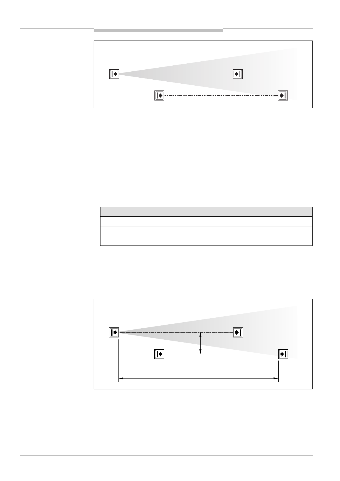
All reflective surfaces and objects (e.g. material bins) must be a minimum distance a from
the light path between sender and receiver. The minimum distance a depends on the
distance D between sender and receiver.
reflective surfaces
Note
The field of view of the sender and receiver optics is identical.
8012247/RI61/2007-11-30 © SICK AG • Industrial Safety Systems • Germany • All rights reserved 33
Page 34

Chapter 5 Operating Instructions
Fig.20:
Graph, minimum
Tab.17:
Formula for the
Fig.21:
Sender and receiver
distance from reflective
surfaces
Installation and mounting
C4000 Select
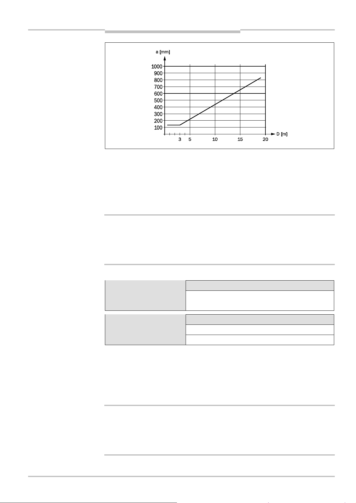
How to determine the minimum distance from reflective surfaces:
Determine the distance D [m] sender–receiver.
The minimum distance to the reflective surface a [mm] is shown in the diagram below
or may be calculated using the formula shown in Tab. 17.
calculation of the minimum
distance to reflective
surfaces
WARNING
must not be rotated 180°
with respect to each other
Distance D [m]
sender–receiver
D 3 m a [mm] = 131
D > 3 m a [mm] = tan(2.5°) × 1000 × D [m] = 43.66 × D [m]
Calculation of the minimum distance a from reflective
surfaces
)
4
5.2 Steps for mounting the device
Special features to note during mounting:
Always mount the sender and receiver parallel to one another.
During mounting, ensure that sender and receiver are aligned correctly. The optical lens
systems of sender and receiver must be located in exact opposition to each other; the
status indicators must be mounted at the same height. The system connections of both
devices must point in the same direction.
34 © SICK AG • Industrial Safety Systems • Germany • All rights reserved 8012247/RI61/2007-11-30
4)
The maximum value used for D is 6 m for low scanning range and 19 m for high scanning range.
Page 35

Operating Instructions Chapter 5
Fig.22:
The correct
C4000 Select
Installation and mounting
Observe the safety distance of the system during mounting. On this subject read
hapter 5.1 “Determining the minimum safety distance” on page 29.
c
Mount the safety light curtain such that the risk of failure to detect is excluded. Ensure
that the protective device cannot be bypassed by crawling underneath, reaching over,
climbing between 2 beams, jumping over or moving the safety light curtain.
installation (above) must
eliminate the errors (below)
of reaching through and
crawling beneath
Once the system is mounted, one or several of the enclosed self-adhesive information
labels must be affixed:
– Use only information labels in the language which the users and operators of the
machine understand.
– Affix the information labels such that they are easily visible by the users and
operators during operation. After attaching additional objects and equipment, the
information labels must not be concealed from view.
– Operation with floating blanking: Affix the information label for floating blanking to
each receiver so configured. Mark the effective resolution on the information label.
– Affix the information label “Important Notices” to the system in close proximity to
sender and receiver.
When mounting a C4000 Select with integrated laser alignment aid, ensure that the
laser warning labels on the device remain visible. If the laser warning labels are
covered, e.g. on installation of the C4000 Select in a device column (accessory), you
must apply a laser warning label in an appropriate location in close proximity to the
sender unit.
8012247/RI61/2007-11-30 © SICK AG • Industrial Safety Systems • Germany • All rights reserved 35
Page 36

Chapter 5 Operating Instructions
Fig.23:
Composition of the
Part No.
2030510
Note
swivel mount bracket
Installation and mounting
C4000 Select
Sender and receiver can be mounted in four different ways:
mounting with swivel mount bracket
mounting with side bracket
mounting with rigid mounting bracket
mounting with pivoting mounting bracket
5.2.1 Mounting with swivel mount bracket
The swivel mount bracket is made of high-strength black plastic. The bracket is designed
such that sender and receiver can still be accurately aligned even after the bracket has
been mounted.
Attach the screws of the swivel mount bracket with a torque of between 2.5 and 3 Nm.
Higher torques can damage the bracket; lower torques provide inadequate protection
against vibration.
36 © SICK AG • Industrial Safety Systems • Germany • All rights reserved 8012247/RI61/2007-11-30
Page 37

Operating Instructions Chapter 5
Fig.24:
Mounting the
C4000
C4000 Select
Select with swivel mount
bracket
Installation and mounting
Notes
Mount the bolts marked with to on the operator side of the system to ensure that
they remain accessible after mounting. The safety light curtain can then also be adjusted later.
The mounting nuts and bolts are not included in the delivery.
8012247/RI61/2007-11-30 © SICK AG • Industrial Safety Systems • Germany • All rights reserved 37
Page 38

Chapter 5 Operating Instructions
Fig.25:
Composition of the
Part No. 2019506
side bracket
Installation and mounting
C4000 Select
5.2.2 Mounting with side bracket
The side bracket is made of die cast zinc ZP 0400. It is enamelled in black. The side
bracket will be covered by the device after mounting. It provides adjustment so that the
vertical alignment of sender and receiver can be corrected by ±2.5° after mounting.
Notes
Attach the bolts of the side bracket with a torque of between 5 and 6 Nm. Higher
torques can damage the bracket; lower torques provide inadequate protection against
vibration.
38 © SICK AG • Industrial Safety Systems • Germany • All rights reserved 8012247/RI61/2007-11-30
Page 39

Operating Instructions Chapter 5
Fig.26:
Mounting the
C4000
Sliding nut
Sliding nut
C4000 Select
Select with side bracket
Installation and mounting
Notes
When mounting the side bracket ensure that the bolts marked and remain
accessible, allowing you later to adjust and lock the safety light curtain in position.
The mounting nuts and bolts are not included in the delivery.
8012247/RI61/2007-11-30 © SICK AG • Industrial Safety Systems • Germany • All rights reserved 39
Page 40

Chapter 5 Operating Instructions
Fig.27:
Rigid mounting
Fig.28:
Mounting the
C4000
Part No.
7021352
Sliding nuts
Sliding nuts
Installation and mounting
C4000 Select
5.2.3 Mounting with rigid mounting bracket
The rigid mounting bracket is a black, powder-coated bracket without adjustment. It is only
suitable for mounting surfaces on which it is not necessary to compensate for large
mechanical tolerances. The alignment of the sender and receiver can be corrected after
mounting using only the slots.
bracket
Select with rigid mounting
bracket
Notes
When mounting the rigid mounting bracket ensure that the four bolts marked and
remain accessible, allowing you later to adjust and lock the safety light curtain in
position.
The mounting nuts and bolts are not included in the delivery.
40 © SICK AG • Industrial Safety Systems • Germany • All rights reserved 8012247/RI61/2007-11-30
Page 41

Operating Instructions Chapter 5
C4000 Select
Installation and mounting
5.3 Laser alignment
he C4000 Select provides an internal, collimated, visible class 1 laser to assist you with
T
the alignment of C4000 Select sender and receiver units. The laser used for aligning the
sender to receiver is located in the C4000 Select sender unit. Further adjustments should
e performed at the C4000 Select receiver unit until the system is properly aligned.
b
To activate the laser, locate the button near the DIP switches in the C4000 Select sender
unit. Press the button for more than 0.25 seconds. Once pressed and released, the laser
will be illuminated for four (4) minutes. If the button is pressed again, it will shut the laser
off.
The signal indicator on the C4000 Select receiver unit indicates the current state of alignment between it and the corresponding sender unit. There are five (5) LEDs that are rela-
ted to this function. When the first LED is yellow, the synchronization beam of the sender
and receiver has been detected. As the percentage of beams increases, the number of
yellow LEDs that are illuminated also increase. When all five LEDs are illuminated yellow,
the sender and receiver units are aligned, but there is a weak signal. When all five LEDs
are illuminated green, the sender and receiver units are aligned with adequate signal
detected.
Note
The laser alignment tool of the C4000 Select is rated to
laser safety class 1. Additional measures for screening the
laser radiation are not necessary.
This device meets the standard CDRH 21 CFR 1040.10 as well as EN 60825@1:2007.
There the following note is required: “Caution — use of controls or adjustments or perfor-
mance of procedures other than those specified herein may result in hazardous radiation
exposure!”
The laser is used to align the optics between a single sender and receiver pair. However,
when a cascaded system is implemented, the laser from one C4000 Select sender could
cause a lockout condition in a receiver in another C4000 Select sender/receiver pair in
the cascade. If this lockout condition occurs, cycle power and perform the alignment pro-
cedure again.
8012247/RI61/2007-11-30 © SICK AG • Industrial Safety Systems • Germany • All rights reserved 41
Page 42

Chapter 5 Operating Instructions
Fig.29:
C4000 Select laser
alignment location and label
details
Installation and mounting
C4000 Select
Aperture of integrated laser,
located on C4000 Select
sender unit
The laser warning label has been incorporated into the device
type label information located on the back of the C4000 Select
sender unit just above the system end cap.
Laser target area,
located on C4000 Select
receiver unit
WARNING
Do not look into the laser aperture!
The laser alignment aid of the C4000 Select sender unit is rated Class 1 (eye safe) to
applicable standards. However, as with any source of radiated energy (e.g. light), prolonged, direct exposure to laser light may cause damage to vision.
42 © SICK AG • Industrial Safety Systems • Germany • All rights reserved 8012247/RI61/2007-11-30
Page 43

Operating Instructions Chapter 6
C4000 Select
Electrical installation
6 Electrical installation
Switch the entire machine/system off line!
WARNING
The machine/system could inadvertently start up while you are connecting the devices.
Ensure that the entire machine/system is disconnected during the electrical
nstallation.
i
Connect OSSD1 and OSSD2 separately!
You are not allowed to connect OSSD1 and OSSD2 together, otherwise signal safety will
not be ensured.
Ensure that the machine controller processes the two signals separately.
Contactors connected in series must be positively guided and monitored.
Notes
The two outputs are protected against short-circuits to 24 V DC and 0 V. When the light
path is clear, the signal level on the outputs is HIGH DC (at potential), when the light
beams are interrupted or there is a device fault the outputs are LOW DC.
The safety light curtain C4000 Select meets the interference suppression requirements
(EMC) for industrial use (interference suppression class A). When used in residential
areas it can cause interference.
To ensure full electromagnetic compatibility (EMC), functional earth (FE) must be
connected.
The external voltage supply of the devices must be capable of buffering brief mains
voltage failures of 20 ms as specified in EN 60204@1. The power supply unit must
provide safe isolation (SELV/PELV). Suitable power supplies are available as
accessories from SICK (see section 12.11 “Accessories” on page 75).
System connections and extension connections in a cascaded system must be connect-
ed only if the system is off line.
8012247/RI61/2007-11-30 © SICK AG • Industrial Safety Systems • Germany • All rights reserved 43
Page 44

Chapter 6 Operating Instructions
Fig.30:
Pin assignment for
Tab.18:
Pin assignment for
Electrical installation
C4000 Select
6.1 Bottom end cap with system connection M12× 5 male
system connection M12× 5
male
system connection M12× 5
male
Pin No. Wire Color5)Sender Receiver Description
1 Brown +24 V DC +24 V DC Supply voltage (+)
2 White – OSSD1 Output Signal Switching Device 1
3 Blue 0 V DC 0 V DC Supply voltage (–)
4 Black – OSSD2 Output Signal Switching Device 2
5 Gray FE FE Functional Earth
6.2 Bottom end cap with system connection M12× 5 male
and extended I/O connection M12× 5 female
In addition to the system connection, the C4000 Select may have an extended I/O connection included in the same end cap. This extended I/O connection is used for cascading ad-
ditional protective devices (e.g. another C4000 Select or SICK S300/S3000 safety laser
scanner). Connection of the safety-rated outputs associated with these additional casca-
ded devices occurs at the extended I/O connection of the C4000 Select receiver.
Only PNP-type semiconductor-based safety outputs may be connected via the extended
I/O connection. Electro-mechanical devices (i.e. contact-based devices) are strictly prohibited from being connected to the extended I/O connection.
When cascading C4000 Select devices via the extended I/O connection, the sender unit
may also utilize an extended I/O connection for ease of wiring.
Electro-mechical devices are not to be connected to the safety inputs on the extended
WARNING
I/O connection!
Extended I/O connections allow you to cascade additional devices to the C4000 Select.
When implementing such a system, you are only allowed to connect PNP-type semiconduc-
tor safety-rated devices to the safety inputs on the extended I/O connection. Electromechanical devices (e.g. emergency stops, safety interlock switches, etc.) shall not be
connected to the safety inputs on the extended I/O connection!
5)
Wire colors shown in this table are in accordance with SICK C4000 Select M12× 5 cable accessories. When
utilizing other M12× 5 cable manufacturers’ cables, you may need to verify that the conductor colors shown in
this table correspond with the cable that you are using.
44 © SICK AG • Industrial Safety Systems • Germany • All rights reserved 8012247/RI61/2007-11-30
Page 45

Operating Instructions Chapter 6
Fig.31:
Pin assignment for
Tab.19:
Pin assignment for
Tab.20:Pin assignment for
C4000 Select
system connection M12× 5
male and M12× 5 female
Electrical installation
Male Female
system connection M12× 5
male
extended I/O connection
M12× 5 female
Pin No. Wire Color6)Sender Receiver Description
1 Brown +24 V DC +24 V DC Supply voltage (+)
2 White – OSSD1 Output Signal Switching Device 1
3 Blue 0 V DC 0 V DC Supply voltage (–)
4 Black – OSSD2 Output Signal Switching Device 2
5 Gray FE FE Functional Earth
Pin No. Wire Color6)Sender Receiver Description
1 Brown +24 V DC +24 V DC Supply voltage (+)
2 White – IN1 Safe input 1
3 Blue 0 V DC 0 V DC Supply voltage (–)
4 Black – IN2 Safe input 2
5 Gray FE FE Functional Earth
8012247/RI61/2007-11-30 © SICK AG • Industrial Safety Systems • Germany • All rights reserved 45
6)
Wire colors shown in this table are in accordance with SICK C4000 Select M12× 5 cable accessories. When
utilizing other M12× 5 cable manufacturers’ cables, you may need to verify that the conductor colors shown in
this table correspond with the cable that you are using.
Page 46

Chapter 6 Operating Instructions
Fig.32:
Pin assignment for
Tab.21:
Pin assignment for
Electrical installation
C4000 Select
6.3 Top end cap with extended I/O M12× 5 female
connection
In addition to the end cap with the system connection, the C4000 Select may also utilize a
op end cap that has an extended I/O connection that is used for cascading additional
t
protective devices (e.g. another C4000 Select or SICK S300/S3000 safety laser scanner).
Connection of the safety-rated outputs associated with these additional cascaded devices
occurs at the C4000 Select receiver extended I/O connection. When an extended I/O end
cap is used on the top of the C4000 Select receiver unit, the integrated LED cannot be
used. If an integrated LED is required, specify a combined system and extended I/O
bottom end cap when ordering. Refer to section 6.2 “Bottom end cap with system
connection M12×5 male and extended I/O connection M12× 5 female” on page 44 for
additional information.
Only PNP-type semiconductor-based safety outputs may be connected via the extended
I/O connection. Electro-mechanical devices (i.e. contact-based devices) are strictly prohibited from being connected to the extended I/O connection.
When cascading C4000 Select devices via the extended I/O connection, the sender unit
may also utilize an extended I/O connection for ease of wiring.
WARNING
extended I/O connection
M12× 5 female
end cap with extended I/O
connection M12× 5 female
Electro-mechical devices are not to be connected to the safety inputs on the extended
I/O connection!
Extended I/O connections allow you to cascade additional devices to the C4000 Select.
When implementing such a system, you are only allowed to connect PNP-type semiconduc-
tor safety-rated devices to the safety inputs on the extended I/O connection. Electromechanical devices (e.g. emergency stops, safety interlock switches, etc.) shall not be
connected to the safety inputs on the extended I/O connection!
Pin No. Wire Color7)Sender Receiver Description
1 Brown +24 V DC +24 V DC Supply voltage (+)
2 White – IN1 Safe input 1
3 Blue 0 V DC 0 V DC Supply voltage (–)
4 Black – IN2 Safe input 2
46 © SICK AG • Industrial Safety Systems • Germany • All rights reserved 8012247/RI61/2007-11-30
5 Gray FE FE Functional Earth
7)
Wire colors shown in this table are in accordance with SICK C4000 Select M12× 5 cable accessories. When
utilizing other M12× 5 cable manufacturers’ cables, you may need to verify that the conductor colors shown in
this table correspond with the cable that you are using.
Page 47

Operating Instructions Chapter 7
Tab.22:
Displays shown
C4000 Select
Commissioning
7 Commissioning
Commissioning requires a thorough check by qualified safety personnel!
WARNING
Before you operate a system protected by the C4000 Select safety light curtain for the first
ime, make sure that the system is first checked and released by qualified safety person-
t
nel. Please read the notes in chapter “On safety” on page 9.
7.1 Display sequence during power-up
After the system is activated, sender and receiver go through a power-up cycle. The 7@segment display indicates the device status during the power-up cycle.
The display values have the following meaning:
during the power-up cycle
WARNING
Display Meaning
, , , ,
, , ,
0.5 s (typical). Is displayed only at the receiver and only in operation
, or 0.5 s (typical). Non-coded operation or operation with code 1 or 2.
Other display Device error. See “Fault diagnosis” on page 52.
Testing the 7@segment display. All segments are activated
sequentially.
with high scanning range.
7.2 Aligning sender and receiver
After the light curtain has been mounted and connected, the sender and receiver must be
aligned in relation to each other. The light beams emitted by the sender must hit the receiver with pin-point accuracy. For additional information regarding the laser alignment
capability of the C4000 Select, see section 5.3 “Laser alignment” on page 41.
How to align sender and receiver in relation to each other:
Secure the plant/system. No dangerous movement possible!
Make sure that the dangerous state of the machine is (and remains) switched off! During
the alignment process, the outputs of the safety light curtain are not allowed to have any
effect on the machine.
8012247/RI61/2007-11-30 © SICK AG • Industrial Safety Systems • Germany • All rights reserved 47
Loosen the clamping bolts which hold the light curtain in place.
Switch on the power supply to the light curtain.
Watch the five (5) alignment LEDs on the receiver unit. As the number of illuminated
LEDs increases, an increased percentage of beams are aligned between sender and
receiver unit. When all beams are aligned, all five (5) LEDs will be illuminated. If all five
(5) LEDs are yellow, then there is a weak signal between sender and receiver. If all five
(5) LEDs are green, then the alignment is correct with adequate signal strength.
Using the clamping bolts, fix the light curtain in place.
Switch the power supply off and then back on again and check the five (5) alignment
LEDs to ensure alignment is still adequate.
Page 48

Chapter 7 Operating Instructions
Commissioning
C4000 Select
Notes
The laser alignment mode will be active for four (4) minutes after activation. To reacti-
ate the laser alignment mode, press the laser activation button on the sender device.
v
If you wish to readjust the alignment later, press the laser activation button on the
C4000 Select sender unit.
The safety outputs of a host C4000 Select system that is cascaded will remain inactive
(low) i.e. red until all guests have been correctly aligned and their corresponding outputs
are active (high) i.e. green.
7.3 Test notes
The purpose of the tests described in the following is to confirm the safety requirements
specified in the national/international rules and regulations, especially the safety require-
ments in the Machine and Work Equipment Directive (EU Conformity).
These tests are also used to identify if the protection is affected by external light sources
or other unusual ambient effects.
These tests must therefore always be performed.
7.3.1 Tests before the first commissioning
Check the effectiveness of the protective device mounted to the machine, using all
selectable operating modes as specified in the checklist in the annex (see 13.2 on
page 78).
Ensure that the operating personnel of the machine in which the C4000 Select is in-
stalled are correctly instructed by qualified safety personnel before being allowed to
operate the machine. Instructing the operating personnel is the responsibility of the
machine owner.
Annex 13.2 of this document shows a checklist for review by the manufacturer and
OEM. Use this checklist as a reference before commissioning the system for the first
time.
7.3.2 Regular inspection of the protective device by qualified safety personnel
Check the system, following the inspection intervals specified in the national rules and
regulations. This procedure ensures that any changes on the machine or manipulations
of the protective device are detected before use/re-use.
If any modifications have been made to the machine or the protective device, or if the
safety light curtain has been changed or repaired, the system must be checked again as
specified in the checklist in the annex.
48 © SICK AG • Industrial Safety Systems • Germany • All rights reserved 8012247/RI61/2007-11-30
Page 49

Operating Instructions Chapter 7
Fig.33:
Daily checks of the
C4000 Select
Note
WARNING
Commissioning
7.3.3 Daily functional checks of the protective device
The effectiveness of the protective device must be checked daily by a specialist or by
authorized personnel, using the correct test rod.
Always test along the complete hazardous area to be protected, never solely at the
mounting position of the light curtain.
How to check the effectiveness and correct function of the safety light curtain:
Select the correct test rod depending on device resolution. By means of the configura-
tion, the entire system or individual areas can have a physical resolution that is different to the effective resolution, e.g. in case of floating blanking. In this case you must
select the test rod to suit the effective resolution. The effective resolution is described
with the related function in chapter 4.
Example: – physical resolution 30 mm
– operation with single beam floating blanking
– effective resolution 50 mm
Use a test rod for a resolution of 50 mm.
Do not operate the machine if the output LED turns green during the test!
If the output LED turns green during the test, even for a short period, work must stop at
the machine. In this case the mounting and the configuration of the safety light curtain
must be checked by qualified safety personnel (see chapter 5).
Before inserting the test rod, ensure that the output LED is green and the protective
field is clear of obstruction. Once the test rod is inserted, the output LED should remain
red during the entire time the test rod is present in the protective field. This test is
meaningless if it is completed when the output LED is already red before the test rod
has been inserted into the protective field.
protective device
Note
Move the test rod slowly through the protective field to be tested, as shown in in
Fig. 33.
Then move the test rod along the edges of the protective field, as shown in in Fig. 33.
This procedure allows you to test if the point-of-operation/reaching around protection is
functioning correctly (see 5.2 “Steps for mounting the device” on page 34).
If you use one or more deflector mirrors (e.g. PNS), then also guide the test rod slowly
through the protective field directly in front of the mirrors.
During all tests, the output LED should remain red.
8012247/RI61/2007-11-30 © SICK AG • Industrial Safety Systems • Germany • All rights reserved 49
Page 50

Chapter 8 Operating Instructions
Tab.23:
Default DIP switch
Tab.24:
Default DIP switch
Tab.25:
Default DIP switch
Configuration
C4000 Select
8 Configuration
Default delivery status
As delivered the C4000 Select is configured ready for protective operation. The following
tables indicate the default switch settings for C4000 Select sender and receiver units:
settings for C4000 Select
sender unit
settings for C4000 Select
receiver unit when extended
I/O connection is not present
settings for C4000 Select
receiver unit when extended
I/O connection is available
Switch Description Default setting (out of box)
Beam code 1 select OFF i.e. no beam coding
Beam code 2 select OFF i.e. no beam coding
Switch Description Default setting (out of box)
High range select OFF i.e. low range
Extended I/O enable OFF i.e. no extended I/O
Beam code 1 select OFF
i.e. no beam coding
Beam code 2 select OFF
Floating blanking enable OFF i.e. disabled
One beam floating blanking OFF i.e. disabled
Two beam floating blanking OFF i.e. disabled
Switch Description Default setting (out of box)
High range select OFF i.e. low range
Extended I/O enable ON i.e. extended I/O enabled
Beam code 1 select OFF
i.e. no beam coding
Beam code 2 select OFF
Floating blanking enable OFF i.e. disabled
One beam floating blanking OFF i.e. disabled
Two beam floating blanking OFF i.e. disabled
50 © SICK AG • Industrial Safety Systems • Germany • All rights reserved 8012247/RI61/2007-11-30
Page 51

Operating Instructions Chapter 9
C4000 Select
Care and maintenance
9 Care and maintenance
The C4000 Select safety light curtain is maintenance-free. The front screen of the C4000
Select safety light curtain and any additional front screen(s) (see “Additional front screen
(weld spark guard)” on page 74) should be cleaned at regular intervals and when dirty.
Do not use aggressive cleaning agents.
Do not use abrasive cleaning agents.
Note
Note
Static charges cause dust particles to be attracted to the front screen. You can prevent
this effect by using the antistatic plastic cleaner (SICK part number 5600006) and the
SICK lens cloth (part number 4003353).
How to clean the front screen and/or the additional front screen (optional extra):
Use a clean and soft brush to remove dust from the front screen.
Then wipe the front screen with a clean and damp cloth.
After cleaning, check the position of sender and receiver to make sure that the
protective device cannot be bypassed (reaching over, under or around).
Verify the effectiveness of the protective device as described in chapter 7.3 “Test
notes” on page 48.
WARNING
Only factory authorized personnel may repair C4000 Select devices!
The C4000 Select is designed for maintenance-free operation. When a device requires
repair, contact your local SICK representative to coordinate the repair or exchange of the
device. Do not attempt to repair the device yourself! Any attempt to repair your C4000
Select device (e.g. removal of end cap, etc.) will void product warranty and may lead to the
loss of the safety function!
Use of controls or adjustments or performance of procedures other than those specified in
this document may result in hazardous radiation exposure per EN 60825. Do not attempt
to disassemble this sensor for repair! A defective device must be returned to the manufacturer or a regional repair center authorized by the manufacturer for the repair of this
device.
8012247/RI61/2007-11-30 © SICK AG • Industrial Safety Systems • Germany • All rights reserved 51
Page 52

Chapter 10 Operating Instructions
Tab.26:
C4000 Select
LED
Fault diagnosis
C4000 Select
10 Fault diagnosis
This chapter describes how to identify and rectify errors and malfunctions during the
operation of the safety light curtain.
10.1 What to do in case of faults
Cease operation if the cause of the malfunction has not been clearly identified!
WARNING
Stop the machine if you cannot clearly identify or allocate the error and if you cannot safely
remedy the malfunction.
The system state lock-out
In case of certain faults or an erroneous configuration, the system can go into the lock@out
status. The 7@segment display on the safety light curtain then indicates a number ranging
from 1 through 6. To place the device back in operation:
Rectify the cause of the fault as per Tab. 28.
Switch the power supply for the C4000 Select off and on again (e.g. by unplugging the
system connection and reinserting it).
troubleshooting on sender
unit
10.2 SICK Support
If you cannot remedy an error with the help of the information provided in this chapter,
please contact your local SICK representative.
10.3 Error displays of the diagnostics LEDs
This chapter explains the meaning of the error displays of the LEDs and how to respond.
Please refer to the description in chapter 3.4 “Status indicators and C4000 Select
message center” on page 18.
LED Name Display Possible cause Rectification
POWER Off
REPLACE Red
No operating voltage, or
voltage too low
The sender unit has detected
an internal error.
Check the voltage supply
and activate, if necessary.
Cycle power. If the error
persists, replace sender unit
52 © SICK AG • Industrial Safety Systems • Germany • All rights reserved 8012247/RI61/2007-11-30
Page 53

Operating Instructions Chapter 10
Tab.27:
C4000 Select
LED
C4000 Select
Fault diagnosis
troubleshooting on receiver
unit
LED Name Display Possible cause Rectification
OUTPUT Off No operating voltage, or
voltage too low
EXT I/O Red Extended I/O safety inputs
are inactive (low) i.e. OFF
Check the voltage supply
and activate, if necessary.
Check guest device(s) to
ensure that their outputs
are active (high).
Check wiring for errors.
Check DIP switches to
ensure that the settings
are correct
ALIGNMENT
LEDs
Not all
LEDs are
Green
Not all beams are aligned
between sender and
receiver units
Check alignment and
make any necessary
adjustments in order to
have all five alignment
LEDs Green
Clean C4000 Select front
windows
8012247/RI61/2007-11-30 © SICK AG • Industrial Safety Systems • Germany • All rights reserved 53
Page 54

Chapter 10 Operating Instructions
Tab.28:
Error displays of the
Fault diagnosis
C4000 Select
10.4 Error displays of the 7?segment display
his chapter explains the meaning of the error displays of the 7@segment display and how
T
to respond to the messages. Please refer to chapter 3.4 “Status indicators and C4000
Select message center” on page 18 for a description of the 7@segment display.
7>segment display
7?segment
display
Display Possible cause Rectification
An internal error has been
detected
A configuration error has
been detected
Receiver unit has detected
beams from multiple sender
units
Power supply voltage too low Check the supply voltage
A fault or unexpected state
has been detected at the
OSSDs on the system
connection (e.g. overcurrent,
stuck-at-high, or stuck-atlow)
An unexpected signal has
been detected at the
extended I/O connection
(e.g. discrepancy error or
active signal at extended I/O
safety inputs when extended
I/O is disabled)
Cycle power. If the error
condition persists,
replace receiver unit
Check DIP switch settings
Add beam coding for
guest segment(s)
and the power supply. If
necessary, replace
defective components
Check system wiring for
errors
Verify guest device safety
outputs are either both
active (high) or inactive
(Low) (e.g. equivalent)
Check guest device(s)
wiring to the C4000
Select host device.
Verify guest device is
operating correctly
If extended I/O function is
disabled, verify no guest
device is connected at
extended I/O connection
If no extended I/O
connection is present and
this error code exists,
replace device
54 © SICK AG • Industrial Safety Systems • Germany • All rights reserved 8012247/RI61/2007-11-30
Page 55

Operating Instructions Chapter 11
Tab.29:
Data sheet
C4000
C4000 Select
Technical specifications
11 Technical specifications
11.1 Data sheet
Select
Minimum Typical Maximum
General system data
Protective field height, depending
300 mm 1800 mm
on type
Resolution
30 mm
Scanning range, DIP switch
configurable
Low range
0…6 m 0…7.5 m
High range 5…19 m 5…21 m
Protection class
(EN 50178:1997@10)
9)
Enclosure rating (IEC 60529)
Supply voltage UVat device
Residual ripple
11)
10)
Synchronization
III
IP 65
19.2 V DC 24 V DC 28.8 V DC
Optical, without separate synchronization
Type according to IEC 61496 Type 4
SIL CL according to IEC 62061
Category/performance level according to EN ISO 13849@1:2006
SIL according to IEC 61508
PFHdstand-alone 1800 mm
PFHdhost-guest-guest 1800 mm 3.2 × 10
Mission time/proof test interval
Category according to EN 954@1
12)
SIL CL 3
Category 4/PL e
12)
SIL 3
1.5 × 10
20 years
13)
Category 4
-8
-8
Power-up delay of sender and
receiver before ready
8)
8)
± 10%
8 s
Sender unit
Wavelength of sender 950 nm
Power consumption
See Tab. 30
Permissible line resistance
Supply lead 1
8)
On the utilization of this protective field width, it must be expected the yellow alignment LEDs will be yellow
(cleaning or realignment required). The system then only has a reserve of 30%.
9)
Safety extra-low voltage SELV/PELV.
10)
The external voltage supply must be capable of buffering brief mains voltage failures of 20 ms as specified in
EN 60204@1. Suitable power supplies are available as accessories from SICK.
11)
Within the limits of UV.
12)
For detailed information regarding the accurate interpretation of this data, please contact your local SICK
representative.
13)
EN 954@1 is valid until 29.11.2009. After this date, only its successor EN ISO 13849@1:2006 may be used.
8012247/RI61/2007-11-30 © SICK AG • Industrial Safety Systems • Germany • All rights reserved 55
Page 56

Chapter 11 Operating Instructions
Technical specifications
C4000 Select
Minimum Typical Maximum
Alignment laser Class 1 in accordance with IEC 60825@1:2007 and
1 CFR 1040.10 and 1040.11 except for
2
deviations pursuant to Laser Notice No. 50, June
24, 2007, optical output power 390 µW CW
= 650 nm
typical
Weight, type dependent
Depending on protective field height (see page 63)
Receiver unit
Switching outputs (OSSDs) Dual-channel, PNP semiconductor, short-circuit
14)
protected
, cross-circuit monitored
Response time See chapter 11.2 on page 58
Switch off time
Switching voltage
(active, U
Switching voltage
15)
16) 17)
HIGH
)
eff
16)
LOW
100 ms
UV– 2.25 V DC 24 V DC U
V
0 V 0 V 2.0 V DC
(inactive)
Switching current 0 mA 500 mA
Leakage current
18)
0.25 mA
Load capacity 2.2 µF
Switching sequence Depending on load inductance
20)
19)
2.2 H
Load inductance
Test pulse data
Test pulse width 120 µs 150 µs 300 µs
Test pulse rate 3 1/s 5 1/s 10 1/s
Permissible line resistance
between device and load
21)
2.5
Supply lead 1
Power consumption See Tab. 30
14)
Applies to the voltage range between –30 V DC and +30 V DC.
15)
Switch off time represents the minimum amount of time that the OSSDs will be switched off when the C4000
Select transitions to an inactive (low) (i.e. red) state.
16)
As per IEC 61131@2.
17)
On the device plug.
18)
In the case of a fault (0 V cable open circuit) the max. leakage current flows in the OSSD cable. The downstream controller must detect this status as LOW. A FPLC (Fail-safe Programmable Logic Controller) must be
able to identify this status.
19)
The maximum rated load inductance is higher with lower switching sequence.
20)
When active, the outputs are tested cyclically (brief LOW). When selecting the downstream controllers, make
sure that the test pulses do not result in deactivation when using the above parameters.
21)
Make sure to limit the individual line core resistance to the downstream controller to this value to ensure that
a short-circuit between the outputs is safely detected. (Also note EN 60204 Electrical Machine Equipment,
Part 1: General Requirements.)
56 © SICK AG • Industrial Safety Systems • Germany • All rights reserved 8012247/RI61/2007-11-30
Page 57

Operating Instructions Chapter 11
Technical specifications
C4000 Select
Minimum Typical Maximum
2)
Extended I/O input type
according to EN 61131@2)
(
2
Type 3
xternally short-circuit protected, externally cross-
e
. Dual-channel, PNP semiconductor,
circuit monitored e.g. from an S3000 safety laser
scanner or another C4000 Select receiver
3)
nput voltage
I
nput current HIGH 3 mA 5 mA 7 mA
I
2
HIGH
1 V DC 24 V DC 30 V DC
1
Input voltage LOW –30 V DC 0 V DC 5 V DC
Input current LOW –1.2 mA 0 mA 2.5 mA
24)
Input capacitance 5 nF
Input test pulse filtering
25)
Test pulse rate 160/s
Test pulse gap 700 µs
Safe input discrepancy time 20 ms
Operating data
System connection
Maximum cable length
26)
M12× 5, male
30 m
Extension connection M12× 5, female
Maximum cable length
10 m
Ambient operating temperature 0°C +55°C
Air humidity (non-concensing) 15%95%
Storage temperature –25°C +70°C (24 h)
Enclosure rating
27)
IP 65
Housing cross-section 52 mm × 55.5 mm
Vibration resistance 5 g, 10-55 Hz acc. to IEC 60068@2@6
Shock resistance 10 g, 16 ms acc. to IEC 60068@2@29
Environmental data, materials
Housing Aluminium alloy ALMGSI 0.5 (powder coated)
Front screen Polycarbonate, scratch-resistant coating
End caps Polyamide 6.6 CF30
Packaging Corrugated cardboard with Instapak® inlays
Circuit boards Glass-fibre reinforced epoxy resin with flame
retarding agent TBBPA
22)
The “Type” designation listed here describes the kind of inputs that may be connected to the extended I/O
safety input connection. This particular designation is not related to the “Type” designation defined by
IEC 61496@1, @2.
23)
As per IEC 61131@2, type 3.
24)
Maximum leakage current allowed, even in the event of an error or fault condition.
25)
These values indicate the filtering capability of the C4000 Select in evaluating OSSD signals at the extended
I/O safety capable inputs without generating a stop condition based on the test pulse occurrence.
26)
Depending on load, power supply and wire cross-section. The technical specifications must be observed; e.g.
supply voltage and permissible line resistance.
27)
In order to satisfy enclosure rating, the cover plate over the DIP switches must be secured correctly. Further,
system and extended I/O cables must be rated IP 65 or better and must also be attached to the C4000 Select
correctly. You must use protective caps that are suitable for IP 65 enclosure rating for any unused connectors.
8012247/RI61/2007-11-30 © SICK AG • Industrial Safety Systems • Germany • All rights reserved 57
Page 58

Chapter 11 Operating Instructions
Tab.30:
C4000 Select power
Tab.31:
Response time of
Technical specifications
C4000 Select
consumption information
Power consumption
Protective height Sender unit Receiver unit Sender/receiver pair
300 mm 4.9 W 7.6 W 12.5 W
600 mm 5.3 W 7.9 W 13.2 W
900 mm 5.7 W 8.1 W 13.8 W
1200 mm 6.1 W 8.4 W 14.5 W
1500 mm 6.5 W 8.6 W 15.1 W
1800 mm 6.9 W 8.8 W 15.7 W
11.2 Response time
The response time depends on the following parameters:
number of beams
beam coding
configuration of floating blanking
number of cascaded systems
the output signal switching device used
How to determine the response time of the system:
Determine the response time of the individual components of the system.
– The response time of a C4000 Select standalone or host system is described in sec-
tion 11.2.1 “Calculating the host/standalone response time” on page 58.
– The response time for guest 1 using a C4000 Select system or S300/S3000 safety
laser scanner as guest 1 is described in section 11.2.2 “Calculating the guest 1
response time” on page 59.
– The response time for guest 2 using a C4000 Select system as guest 2 is described
in section 11.2.3 “Calculating the guest 2 response time” on page 60.
You must also consider other components of the response time when performing minimum safety distance calculations. Other components include, but are not limited to, safety
interfaces, safety communication networks, machine stopping time, etc. See section 5.1.1
“Minimum safety distance to the hazardous area” on page 29 for additional information.
the C4000 Select for applications with and without beam
coding
58 © SICK AG • Industrial Safety Systems • Germany • All rights reserved 8012247/RI61/2007-11-30
11.2.1 Calculating the host/standalone response time
The following table provides details for C4000 Select response times based on configura-
tion with (beam code 1 or beam code 2) or without beam coding (uncoded operation). The
information presented in this table is then used to calculate the host/standalone C4000
Select response time.
Protective height
Beam Coding 300 mm 600 mm 900 mm 1200 mm 1500 mm 1800 mm
Uncoded 9 ms 11 ms 12 ms 13 ms 14 ms 15 ms
Beam code 1/2 12 ms 15 ms 18 ms 21 ms 24 ms 27 ms
Page 59

Operating Instructions Chapter 11
Tab.32:
Response time cal-
Tab.33:
Response time cal-
C4000 Select
Technical specifications
Identify the response time value that corresponds to your C4000 Select based on the
eam code DIP switch setting (i.e. Uncoded, Beam code 1 or Beam code 2 operation) and
b
the protective height that is used and then complete the following table:
culation of host/standalone
C4000 Select safety light
curtain
culation of guest 1 devices in
a host-guest 1 system with
C4000 Select as host
Line Description Value
1 C4000 Select response time from Tab. 31 above
2 When floating blanking is enabled, multiply the value from line 1 by
0.50 and enter the result as the value for line 2.
Add lines 1 and 2 together and enter the value for line 3.
3
Line 3 value is the response time for the C4000 Select host.
11.2.2 Calculating the guest 1 response time
The information presented in Tab. 31 “Response time of the C4000 Select for applications
with and without beam coding” also applies for C4000 Select sender/receiver pairs that
are in the guest 1 position. For applications where the guest 1 device is an S300/S3000
safety laser scanner, consult the operating instructions of the S300 or S3000 for the
response time value that will be used in line 4 of the table below.
Identify the response time value that corresponds to your C4000 Select guest 1 based on
the beam code DIP switch setting (i.e. Uncoded, Beam code 1 or Beam code 2 operation)
and the protective height that is used.
Line Description Value
4 Enter the value for the guest 1 response time based on Tab. 31 for
the C4000 Select, or the value determined for the S300/S3000
safety laser scanner
5 If the device in line 4 is a C4000 Select and floating blanking is
enabled, multiply the value on line 4 by 0.50 and enter the result as
the line 5 value.
6 Add lines 4 and 5 together. Enter the result as the line 6 value.
7 Multiply line 1 from the host response time calculation by 0.50 and
then add 2 ms. Enter the result as the line 7 value.
8 Add lines 6 and 7 together. Enter the result in line 8 value.
Line 8 value is the response time of the guest 1 device.
8012247/RI61/2007-11-30 © SICK AG • Industrial Safety Systems • Germany • All rights reserved 59
Page 60

Chapter 11 Operating Instructions
Tab.34:
Response time cal-
Tab.35:
Response time
Technical specifications
C4000 Select
11.2.3 Calculating the guest 2 response time
The information presented in Tab. 31 “Response time of the C4000 Select for applications
with and without beam coding” also applies for C4000 Select sender/receiver pairs that
are in the guest 2 position. Identify the response time value that corresponds to your
guest 2 C4000 Select based on the beam code DIP switch setting (i.e. Uncoded, Beam
code 1 or Beam code 2 operation) and the protective height that is used.
culation of guest 2 devices in
a host-guest 1-guest 2
system with C4000 Select
calculation for standalone
C4000 Select system
Line Description Value
9 Enter the value for the guest 2 response time based on Tab. 31 for
the C4000 Select
10 If floating blanking is enabled, multiply the value on line 9 by 0.50
and enter the result as the line 10 value
11 Add lines 9 and 10 together. Enter the result in line 11 value
12 Multiply line 1 from the host response time calculation by 0.50 and
then add 2 ms. Enter the result as the line 12 value
13 Multiply line 4 from the guest 1 response time calculation by 0.50
and then add 2 ms. Enter the result as the line 13 value
14 Add lines 11, 12 and 13 together. Enter the result in line 14 value.
Line 14 value is the response time of the guest 2 device.
11.2.4 Response time calculation examples
Standalone C4000 Select system
The calculation example shown below is based on the following:
C4000 Select, 300 mm protective height, no beam coding, no floating blanking
Line Description Value
1 C4000 Select response time from Tab. 31 9 ms
2 When floating blanking is enabled, multiply the value from line 1 by
0.50 and enter the result as the value located for line 2
3 Add lines 1 and 2 together and enter the value for line 3.
Line 3 value is the response time for the C4000 Select host.
0 ms
9 ms
60 © SICK AG • Industrial Safety Systems • Germany • All rights reserved 8012247/RI61/2007-11-30
Page 61

Operating Instructions Chapter 11
Tab.36:
Response time cal-
C4000 Select
Technical specifications
C4000 Select host and S3000 safety laser scanner as guest 1
The calculation example shown below is based on the following:
C4000 Select, 900 mm protective height, beam code 1, with 1 beam floating blanking
S3000 safety laser scanner as guest 1 with 60 ms response time based on scanner
configuration
culation for C4000 Select
host and S3000 safety laser
scanner as guest 1
Line Description Value
1 C4000 Select response time from Tab. 31 18 ms
2 When floating blanking is enabled, multiply the value from line 1 by
0.50 and enter the result as the value for line 2
9 ms
3 Add lines 1 and 2 together and enter the value for line 3.
27 ms
Line 3 value is the response time for the C4000 Select host.
4 Enter the value for the guest 1 response time based on Tab. 31 for
the C4000 Select, or the value determined for the S300/S3000
60 ms
safety laser scanner
5 If the device in line 4 is a C4000 Select and floating blanking is
enabled, multiply the value on line 4 by 0.50 and enter the result as
0 ms
the line 5 value.
6 Add lines 4 and 5 together. Enter the result as the line 6 value. 60 ms
7 Multiply line 1 from the host response time calculation by 0.50 and
then add 2 ms. Enter the result as the line 7 value.
11 ms
8 Add lines 6 and 7 together. Enter the result in line 8 value.
Line 8 value is the response time of the guest 1 S3000 safety
71 ms
laser scanner.
8012247/RI61/2007-11-30 © SICK AG • Industrial Safety Systems • Germany • All rights reserved 61
Page 62

Chapter 11 Operating Instructions
Tab.37:
Response time cal-
Technical specifications
C4000 Select
Host-guest 1-guest 2 C4000 Select system
The calculation example shown below is based on the following:
Host C4000 Select, 900 mm protective height, beam code 1, with 1 beam floating
blanking
Guest 1 C4000 Select, 1200 mm protective height, beam code 2, floating blanking is
isabled
d
Guest 2 C4000 Select, 600 mm protective height, uncoded, with 2 beam floating
blanking
culation for host-guest 1guest 2 C4000 Select system
Line Description Value
1 C4000 Select response time from Tab. 31 18 ms
When floating blanking is enabled, multiply the value from line 1 by
2
0.50 and enter the result as the value for line 2
Add lines 1 and 2 together and enter the value for line 3.
3
Line 3 value is the response time for the host C4000 Select.
Enter the value for the guest 1 response time based on Tab. 31 for
4
C4000 Select, or the value determined for the S300/S3000 safety
laser scanner
If the device in line 4 is a C4000 Select and floating blanking is
5
enabled, multiply the value on line 4 by 0.50 and enter the result as
the line 5 value.
6 Add lines 4 and 5 together. Enter the result as the line 6 value. 21 ms
Multiply line 1 from the host response time calculation by 0.50 and
7
then add 2 ms. Enter the result as the line 7 value.
Add lines 6 and 7 together. Enter result in line 8 value.
8
Line 8 value is the response time of the guest 1 C4000 Select.
Enter the value for the guest 2 response time based on Tab. 31 for
9
the C4000 Select
9 ms
27 ms
21 ms
0 ms
11 ms
32 ms
11 ms
If floating blanking is enabled, multiply the value on line 9 by 0.50
10
and enter the result as the line 10 value.
11 Add lines 9 and 10 together. Enter the result in line 11 value. 16.5 ms
Multiply line 1 from the host response time calculation by 0.50 and
12
then add 2 ms. Enter the result as the line 12 value.
Multiply line 4 from the guest 1 response time calculation by 0.50
13
and then add 2 ms. Enter the result as the line 13 value.
Add lines 11, 12 and 13 together. Enter the result in line 14 value.
14
Line 14 value is the response time of the guest 2 C4000 Select.
5.5 ms
11 ms
12.5 ms
40 ms
62 © SICK AG • Industrial Safety Systems • Germany • All rights reserved 8012247/RI61/2007-11-30
Page 63

Operating Instructions Chapter 11
Tab.38:
Weight of sender
Tab.39:
Weight of the
C4000 Select
Technical specifications
11.3 Table of weights
11.3.1 C4000 Select
and receiver C4000 Select
deflector mirrors PNS75
and PNS125
Weight without LED or extension connection [g] (typical)Protective field height
[mm]
300 1.216 kg 1.242 kg
600 2.146 kg 2.149 kg
900 3.076 kg 3.056 kg
1200 4.006 kg 3.963 kg
1500 4.936 kg 4.870 kg
1800 5.866 kg 5.778 kg
Add the following additional weight(s) for options that apply to your C4000 Select system:
Top extension connection 0.011 kg 0.011 kg
Bottom system/extension
connection combination
Status LED N/A 0.017 kg
Sender Receiver
Additional weight considerations [g] (typical)
0.014 kg 0.040 kg
11.3.2 Deflector mirrors PNS75 and PNS125
Weight [g]Mirror height
[mm]
340 1035 1580
PNS75 PNS125
640 1850 2820
940 2680 4080
1240 3510 5345
1540 4340 6610
1840 5170 7870
8012247/RI61/2007-11-30 © SICK AG • Industrial Safety Systems • Germany • All rights reserved 63
Page 64

Chapter 11 Operating Instructions
Fig.34:
Dimensional drawing
Tab.40:
Dimensions depen-
L3L2L1
55.55227.51625
2.21615
10.5
3.6
1
3.5
14
15
80.4
Technical specifications
C4000 Select
11.4 Dimensional drawings
11.4.1 C4000 Select receiver (all variants)
C4000 Select receiver dimensions for front and side views, with system connection, with
system connection and top extension connection, with system and extension connection
on bottom and with top end cap LED; units in mm. Values are typical; consult SICK for
engineering.
C4000 Select receiver (mm)
dent on the protective field
height, C4000 Select receiver
(typical)
64 © SICK AG • Industrial Safety Systems • Germany • All rights reserved 8012247/RI61/2007-11-30
Protective field height L1 L2 L3
300 302 425 440
600 602 725 740
900 902 1025 1040
1200 1202 1325 1340
1500 1502 1625 1640
1800 1802 1925 1940
Page 65

Operating Instructions Chapter 11
Fig.35:
Dimensional drawing
Tab.41:
Dimensions depen-
2.2
10.5
3.6
1
3.5
14
L3L2L1
55.55227.51616
15
15
80.4
C4000 Select
Technical specifications
11.4.2 C4000 Select sender (all variants)
C4000 Select sender dimensions for front and side views, with system connection, with
system connection and top extension connection and with system and extension connection on bottom; units in mm. Values are typical; consult SICK for engineering.
C4000 Select sender (mm)
dent on the protective field
height, C4000 Select sender
(typical)
8012247/RI61/2007-11-30 © SICK AG • Industrial Safety Systems • Germany • All rights reserved 65
Protective field height L1 L2 L3
300 302 425 440
600 602 725 740
900 902 1025 1040
1200 1202 1325 1340
1500 1502 1625 1640
1800 1802 1925 1940
Page 66

Chapter 11 Operating Instructions
Fig.36:
Dime
nsional drawing,
Fig.37:
Dimensional d
rawing,
Part No. 2019506
19509
5.5
34.5151863.6
12.55881359
100496414Part No.
2030510
Technical specifications
C4000 Select
11.4.3 Swivel mount bracket
swivel mount bracket (mm)
side bracket (mm)
11.4.4 Side mount bracket
66 © SICK AG • Industrial Safety Systems • Germany • All rights reserved 8012247/RI61/2007-11-30
Page 67

Operating Instructions Chapter 11
Fig.38:
Standard L>type
Part No. 7021352
C4000 Select
Technical specifications
11.4.5 Standard L-type mounting brackets
mounting bracket (mm)
8012247/RI61/2007-11-30 © SICK AG • Industrial Safety Systems • Germany • All rights reserved 67
Page 68

Chapter 11 Operating Instructions
Fig.39:
Dimensional drawing
Tab.42:
Dimensions for the
10.5
50
S
35
13.3
±60°
114
6.5
L1
L2AL3
4.5
Sliding nut groove for
73
Technical specifications
C4000 Select
11.4.6 Deflector mirror PNS75
deflector mirror PNS75 (mm)
Mounting with
swivel mount bracket
side mounting
deflector mirror PNS75
dependent on the mirror
height
WARNING
Note
Mirror height
S [mm]
340 372 396 460 440
640 672 696 760 740
940 972 996 1060 1040
1240 1272 1296 1360 1340
1540 1572 1596 1660 1640
1840 1872 1896 1960 1940
Dimension
L1 [mm]
Dimension
L2 [mm]
Dimension
L3 [mm]
Dimension
A [mm]
When using deflector mirrors, the effective scanning range is reduced (see Tab. 13 on
page 26).
Do not use deflector mirrors if the formation of droplets or heavy contamination of the
deflector mirrors is to be expected!
The formation of droplets of heavy contamination can be detrimental to the reflection
behavior. The protective function of the system will be affected and the system will thus
become unsafe. This would mean that the operator is at risk.
68 © SICK AG • Industrial Safety Systems • Germany • All rights reserved 8012247/RI61/2007-11-30
Page 69

Operating Instructions Chapter 11
Fig.40:
Dimensional drawing
Tab.43:
Dimensions for the
10.5
50
S
35
13.3
±60°
2.5
164
6.5
L1
L2AL3
4.5
Sliding nut groove for
5050123
C4000 Select
Technical specifications
11.4.7 Deflector mirror PNS125
deflector mirror PNS125
(mm)
Mounting with
swivel mount bracket
side mounting
deflector mirror PNS125
dependent on the mirror
height
WARNING
Note
Mirror height
S [mm]
340 372 396 460 440
640 672 696 760 740
940 972 996 1060 1040
1240 1272 1296 1360 1340
1540 1572 1596 1660 1640
1840 1872 1896 1960 1940
Dimension
L1 [mm]
Dimension
L2 [mm]
Dimension
L3 [mm]
Dimension
A [mm]
When using deflector mirrors, the effective scanning range is reduced (see Tab. 13 on
page 26).
Do not use deflector mirrors if the formation of droplets or heavy contamination of the
deflector mirrors is to be expected.
The formation of droplets of heavy contamination can be detrimental to the reflection
behavior. The protective function of the system will be affected and the system will thus
become unsafe. This would mean that the operator is at risk.
8012247/RI61/2007-11-30 © SICK AG • Industrial Safety Systems • Germany • All rights reserved 69
Page 70

Chapter 12 Operating Instructions
Tab.44:
C4000 Select
Ordering information
C4000 Select
12 Ordering information
12.1 Delivery
C4000 Select sender unit
sender unit
4 sliding nuts for side bracket
C4000 Select receiver unit
receiver unit
4 sliding nuts for side bracket
test rod with diameter corresponding to the physical resolution of the safety light curtain
label “Important Information”
two labels “Effective resolution”
quick start guide
operating instructions on CD-ROM
information label “Operator’s notes”
without extension connection
Deflector mirror
deflector mirror
2 swivel mount brackets
12.2 C4000 Select without extension connection
The following table provides part number and model designation information for C4000
Select sender and receiver units that may be used in standalone operation (as single
system) or as the last segment (guest) of a cascaded system.
Part numbers and model designationsProtective field
height [mm]
300
600
900
1200
1500
1800
Sender only Receiver only
1204061
(XC40S-0303A0A00AA0)
1204068
(XC40S-0603A0A00AA0)
1204071
(XC40S-0903A0A00AA0)
1204118
(XC40S-1203A0A00AA0)
1204119
(XC40S-1503A0A00AA0)
1204112
(XC40S-1803A0A00AA0)
1204063
(XC40E-0303A0A0AAA0)
1204116
(XC40E-0603A0A0AAA0)
1204191
(XC40E-0903A0A0AAA0)
1204102
(XC40E-1203A0A0AAA0)
1204137
(XC40E-1503A0A0AAA0)
1204138
(XC40E-1803A0A0AAA0)
Sender and
receiver
1043111
(XC40P-0303A0A0AAA0)
1043112
(XC40P-0603A0A0AAA0)
1043113
(XC40P-0903A0A0AAA0)
1043114
(XC40P-1203A0A0AAA0)
1043115
(XC40P-1503A0A0AAA0)
1043116
(XC40P-1803A0A0AAA0)
70 © SICK AG • Industrial Safety Systems • Germany • All rights reserved 8012247/RI61/2007-11-30
Page 71

Operating Instructions Chapter 12
Tab.45:
C4000 Select
Tab.46:
C4000 Select
with
Ordering information
C4000 Select
12.3 C4000 Select with integrated LED status indicator
he following table provides part number and model designation information for C4000
T
Select sender and receiver units that may be used in standalone operation (as single sys-
tem) or as the last segment (guest) of a cascaded system. An LED indicator (360° view)
hat provides safety output status information is integrated into the top end cap of the
t
C4000 Select receiver unit.
without extension connection
and integrated LED status
indicator on the receiver unit
Part numbers and model designationsProtective field
height [mm]
300
600
900
1200
1500
1800
Sender only Receiver only
1204061
(XC40S-0303A0A00AA0)
1204068
(XC40S-0603A0A00AA0)
1204071
(XC40S-0903A0A00AA0)
1204118
(XC40S-1203A0A00AA0)
1204119
(XC40S-1503A0A00AA0)
1204112
(XC40S-1803A0A00AA0)
1204139
(XC40E-0303A0A0AAC0)
1204140
(XC40E-0603A0A0AAC0)
1204141
(XC40E-0903A0A0AAC0)
1204142
(XC40E-1203A0A0AAC0)
1204143
(XC40E-1503A0A0AAC0)
1204144
(XC40E-1803A0A0AAC0)
Sender and
receiver
1043117
(XC40P-0303A0A0AAC0)
1043118
(XC40P-0603A0A0AAC0)
1043119
(XC40P-0903A0A0AAC0)
1043120
(XC40P-1203A0A0AAC0)
1043121
(XC40P-1503A0A0AAC0)
1043122
(XC40P-1803A0A0AAC0)
12.4 C4000 Select with top end cap extension connection
The following table provides part number and model designation information for C4000
Select sender and receiver units that may be used in standalone operation (as single sys-
tem) or as a host segment, first guest segment or the last guest segment of a cascaded
system. An extension connection is incorporated into the top end cap of the devices for
connection of extended I/O devices. The system connection is located in the bottom end
cap of the devices.
top end cap extension connection
height [mm]
300
600
900
1200
1500
1800
Part numbers and model designationsProtective field
Sender only Receiver only
1204069
(XC40S-0303A0A00AB0)
1204132
(XC40S-0603A0A00AB0)
1204145
(XC40S-0903A0A00AB0)
1204148
(XC40S-1203A0A00AB0)
1204150
(XC40S-1503A0A00AB0)
1204152
(XC40S-1803A0A00AB0)
1204134
(XC40E-0303A0A0CAB0)
1204146
(XC40E-0603A0A0CAB0)
1204147
(XC40E-0903A0A0CAB0)
1204149
(XC40E-1203A0A0CAB0)
1204151
(XC40E-1503A0A0CAB0)
1204153
(XC40E-1803A0A0CAB0)
Sender and
receiver
1043123
(XC40P-0303A0A0CAB0)
1043124
(XC40P-0603A0A0CAB0)
1043125
(XC40P-0903A0A0CAB0)
1043126
(XC40P-1203A0A0CAB0)
1043127
(XC40P-1503A0A0CAB0)
1043128
(XC40P-1803A0A0CAB0)
8012247/RI61/2007-11-30 © SICK AG • Industrial Safety Systems • Germany • All rights reserved 71
Page 72

Chapter 12 Operating Instructions
Tab.47:
C4000 Select
with
Tab.48:
C4000 Select
with
Ordering information
C4000 Select
12.5 C4000 Select with bottom end cap system and extension connections
The following table provides part number and model designation information for C4000
elect sender and receiver units that may be used in standalone operation (as single sys-
S
tem) or as a host segment, first guest segment or the last guest segment of a cascaded
system. The extension and system connections are both incorporated into the bottom end
cap of the devices. There are no connections on the top end cap of the devices.
bottom end cap extension
connection
Part numbers and model designationsProtective field
height [mm]
300
600
900
1200
1500
1800
Sender only Receiver only
1204154
(XC40S-0303A0A00BA0)
1204156
(XC40S-0603A0A00BA0)
1204158
(XC40S-0903A0A00BA0)
1204160
(XC40S-1203A0A00BA0)
1204162
(XC40S-1503A0A00BA0)
1204164
(XC40S-1803A0A00BA0)
1204155
(XC40E-0303A0A0CBA0)
1204157
(XC40E-0603A0A0CBA0)
1204159
(XC40E-0903A0A0CBA0)
1204161
(XC40E-1203A0A0CBA0)
1204163
(XC40E-1503A0A0CBA0)
1204165
(XC40E-1803A0A0CBA0)
Sender and
receiver
1043129
(XC40P-0303A0A0CBA0)
1043130
(XC40P-0603A0A0CBA0)
1043131
(XC40P-0903A0A0CBA0)
1043132
(XC40P-1203A0A0CBA0)
1043133
(XC40P-1503A0A0CBA0)
1043134
(XC40P-1803A0A0CBA0)
12.6 C4000 Select with bottom end cap system/extension connections and integrated LED status indicator
The following table provides part number and model designation information for C4000
Select sender and receiver units that may be used in standalone operation (as single system) or as a host segment, first guest segment or the last guest segment of a cascaded
system. The extension and system connections are both incorporated into the bottom end
cap of the devices. An LED indicator (360° view) that provides safety output status infor-
mation is integrated into the top end cap of the C4000 Select receiver unit.
bottom end cap extension
connection and integrated
LED status indicator on the
receiver unit
height [mm]
300
600
900
1200
1500
1800
Part numbers and model designationsProtective field
Sender only Receiver only
1204154
(XC40S-0303A0A00BA0)
1204156
(XC40S-0603A0A00BA0)
1204158
(XC40S-0903A0A00BA0)
1204160
(XC40S-1203A0A00BA0)
1204162
(XC40S-1503A0A00BA0)
1204164
(XC40S-1803A0A00BA0)
1204166
(XC40E-0303A0A0CBC0)
1204167
(XC40E-0603A0A0CBC0)
1204168
(XC40E-0903A0A0CBC0)
1204169
(XC40E-1203A0A0CBC0)
1204170
(XC40E-1503A0A0CBC0)
1204171
(XC40E-1803A0A0CBC0)
Sender and
receiver
1043135
(XC40P-0303A0A0CBC0)
1043136
(XC40P-0603A0A0CBC0)
1043137
(XC40P-0903A0A0CBC0)
1043138
(XC40P-1203A0A0CBC0)
1043139
(XC40P-1503A0A0CBAC)
1043140
(XC40P-1803A0A0CBC0)
72 © SICK AG • Industrial Safety Systems • Germany • All rights reserved 8012247/RI61/2007-11-30
Page 73

Operating Instructions Chapter 12
Tab.49:
C4000 Select
with
Tab.50:
C4000 Select
with
Ordering information
C4000 Select
12.7 C4000 Select with bottom extension connection (receiver only)
The following table provides part number and model designation information for C4000
elect sender and receiver units that may be used in a system extending a S300 or S3000
S
safety laser scanner. The extension and system connections are both incorporated into the
bottom end cap of the devices.
bottom end cap extension
connection (receiver only)
Part numbers and model designationsProtective field
height [mm]
300
600
900
1200
1500
1800
Sender only Receiver only
1204061
(XC40S-0303A0A00AA0)
1204068
(XC40S-0603A0A00AA0)
1204071
(XC40S-0903A0A00AA0)
1204118
(XC40S-1203A0A00AA0)
1204119
(XC40S-1503A0A00AA0)
1204112
(XC40S-1803A0A00AA0)
1204155
(XC40E-0303A0A0CBA0)
1204157
(XC40E-0603A0A0CBA0)
1204159
(XC40E-0903A0A0CBA0)
1204161
(XC40E-1203A0A0CBA0)
1204163
(XC40E-1503A0A0CBA0)
1204165
(XC40E-1803A0A0CBA0)
Sender and
receiver
1043141
(XC40P-0303A0A0CCA0)
1043142
(XC40P-0603A0A0CCA0)
1043143
(XC40P-0903A0A0CCA0)
1043144
(XC40P-1203A0A0CCA0)
1043145
(XC40P-1503A0A0CCA0)
1043146
(XC40P-1803A0A0CCA0)
12.8 C4000 Select with bottom extension connection and integrated LED status indicator (receiver only)
The following table provides part number and model designation information for C4000
Select sender and receiver units that may be used in a system extending a S300 or S3000
safety laser scanner. The extension and system connections are both incorporated into the
bottom end cap of the devices. An LED indicator (360° view) that provides safety output
status information is integrated into the top end cap of the C4000 Select receiver unit.
bottom end cap extension
connection and integrated
LED status indicator (receiver
only)
height [mm]
300
600
900
1200
1500
1800
Part numbers and model designationsProtective field
Sender only Receiver only
1204061
(XC40S-0303A0A00AA0)
1204068
(XC40S-0603A0A00AA0)
1204071
(XC40S-0903A0A00AA0)
1204118
(XC40S-1203A0A00AA0)
1204119
(XC40S-1503A0A00AA0)
1204112
(XC40S-1803A0A00AA0)
1204166
(XC40E-0303A0A0CBC0)
1204167
(XC40E-0603A0A0CBC0)
1204168
(XC40E-0903A0A0CBC0)
1204169
(XC40E-1203A0A0CBC0)
1204170
(XC40E-1503A0A0CBC0)
1204171
(XC40E-1803A0A0CBC0)
Sender and
receiver
1043147
(XC40P-0303A0A0CCC0)
1043148
(XC40P-0603A0A0CCC0)
1043149
(XC40P-0903A0A0CCC0)
1043150
(XC40P-1203A0A0CCC0)
1043151
(XC40P-1503A0A0CCC0)
1043152
(XC40P-1803A0A0CCC0)
8012247/RI61/2007-11-30 © SICK AG • Industrial Safety Systems • Germany • All rights reserved 73
Page 74

Chapter 12 Operating Instructions
Tab.51:
Part numbers addi-
Tab.52:
Part numbers
Tab.53:
Part numbers
Ordering information
C4000 Select
12.9 Additional front screen (weld spark guard)
Two additional front screens (weld spark guards) supplied for each part number.
Notes
The additional front screen fits both on the sender and on the receiver.
The additional front screen may be used only if the curved enclosure side is accessible.
An additional front screen reduces the scanning range of the system by 8%. If sender
nd receiver each use an additional front screen, the scanning range will be reduced by
a
16%.
tional front screen (weld
spark guard)
deflector mirror PNS75
Protective field height
[mm]
300 2033235
600 2033237
900 2033239
1200 2033241
1500 2033243
1800 2033245
Part number
12.10 Deflector mirror
12.10.1 Deflector mirror PNS75 for protective field width 0…12 m (total)
Protective field height [mm] Type number Part number
300 PNS75-034 1019414
600 PNS75-064 1019416
900 PNS75-094 1019418
1200 PNS75-124 1019420
1500 PNS75-154 1019422
deflector mirror PNS125
1800 PNS75-184 1019424
Dimensional drawing see Fig. 39 on page 68. Effect on the scanning range see Tab. 13 on
page 26.
12.10.2 Deflector mirror PNS125 for protective field width 4…18.5 m (total)
Protective field height [mm] Type number Part number
300 PNS125-034 1019425
600 PNS125-064 1019427
900 PNS125-094 1019429
1200 PNS125-124 1019431
1500 PNS125-154 1019433
1800 PNS125-184 1019435
Dimensional drawing see Fig. 40 on page 69. Effect on the scanning range see Tab. 13 on
page 26.
74 © SICK AG • Industrial Safety Systems • Germany • All rights reserved 8012247/RI61/2007-11-30
Page 75

Operating Instructions Chapter 12
Tab.54:
Part numbers
C4000 Select
Ordering information
12.11 Accessories
accessories
Part Part number
ystem connection cables
S
M12× 5 connection cable, single-ended female connection with flying
leads
Plug straight/stripped, 2 m 6008899
Plug straight/stripped, 5 m 6009868
Plug straight/stripped, 10 m 6010544
Plug straight/stripped, 15 m 6029215
Plug straight/stripped, 30 m 6032956
M12× 5 connection cable, double-ended connection, male straight
and female straight with FE tied to M12 housing e.g. for use with
UE4400 IP67-rated remote I/O bus nodes.
Plug straight/plug straight, 2 m 2044610
Plug straight/plug straight, 5 m 2044611
Plug straight/plug straight, 10 m 2044612
Plug straight/plug straight, 15 m 2044613
Plug straight/plug straight, 30 m 2044614
Extension connection cables for extended I/O
Used for cascade connection between a host/guest 1 C4000 Select
extension connection and subsequent C4000 Select guest 1/guest 2
system connection.
M12× 5 connection cable, double-ended connections, male and
female for extended I/O connection of a C4000 Select
Plug straight/plug straight, 1 m 6029280
Plug straight/plug straight, 2 m 6025931
Plug straight/plug straight, 5 m 6029282
M12× 5 connection cable, single-ended male connection with flying
leads for extended I/O connection of S300 or S3000
28)
Plug straight/plug straight, 2 m 6026133
Plug straight/plug straight, 5 m 6026134
Plug straight/plug straight, 10 m 6026135
M12 × 5 field attachable connectors. Use with 10 m system cable for
extension cable requirements 5…10 m (e.g. for cascading systems)
Male connector, M12 × 5, straight, unshielded 6022083
Male connector, M12 × 5, right angle, unshielded 6022082
Mounting brackets
Swivel mounting bracket kit (mounting kit 12, see page 66) 2030510
Side mounting bracket kit (mounting kit 6, see page 66) 2019506
Standard “L” type mounting bracket kit (see page 67) 7021352
28)
S300 and S3000 system plugs are sold separately. Please refer to the device operating instructions for
system plug details and ordering information.
8012247/RI61/2007-11-30 © SICK AG • Industrial Safety Systems • Germany • All rights reserved 75
Page 76

Chapter 12 Operating Instructions
Ordering information
C4000 Select
Part Part number
Power supplies
24 V DC 50 W (2.1 A) output, NEC class 2 power supply, SELV,
PELV, 120-240 V AC input, (PS50W-24V)
24 V DC 95 W (3.9 A) output, NEC class 2 power supply, SELV,
PELV, 100-120/220-240 V AC input, (PS95W-24V)
Test wand
Test wand, 30 mm diameter 2022602
Protective caps (e.g. for IP65 integrity)
M12 protective cap for extended I/O connector (female), 10 pieces 2019706
M12 protective cap for system connector (male), 1 piece 5311099
T-splitter
M12 T-splitter used for single connection of sender and receiver
unit(s) in standalone or cascade applications. Maximum load
current not to exceed 4 A.
7028789
7028790
6030664
76 © SICK AG • Industrial Safety Systems • Germany • All rights reserved 8012247/RI61/2007-11-30
Page 77

Operating Instructions Chapter 13
C4000 Select
Annex
13 Annex
13.1 EC declaration of conformity
Note
8012247/RI61/2007-11-30 © SICK AG • Industrial Safety Systems • Germany • All rights reserved 77
You can obtain the complete EC declaration of conformity via the SICK homepage on the
Internet at: www.sick.com
Page 78

Chapter 13 Operating Instructions
Annex
C4000 Select
13.2 Checklist for the manufacturer
Checklist for the manufacturer/OEM for the installation of electro-sensitive
protective equipment (ESPE)
The details on the items listed below must be available at the latest when the system is commissioned for the first
time, depending, however, on the various applications the requirements of which must be reviewed by the manufacturer/OEM.
This checklist should be retained and kept with the machine documentation to serve as reference during recurring
tests.
1. Have the safety rules and regulations been observed in compliance with the
directives/standards applicable to the machine?
2. Are the applied directives and standards listed in the declaration of conformity? Yes No
3. Does the protective device comply with the required category according to EN 954@ 1? Yes No
4. Is the access to the hazardous area/hazardous point only possible through the protective field of
the ESPE?
5. Have appropriate measures been taken to prevent (mechanical point-of-operation guarding)
or monitor unprotected presence in the hazardous area when protecting a hazardous area/
hazardous point and have these been secured against removal?
6. Are additional mechanical protective measures fitted and secured against manipulation which
prevent reaching under, over or around the ESPE?
7. Has the maximum shutdown and/or stopping time of the machine been measured, specified
and documented (at the machine and/or in the machine documentation)?
8. Has the ESPE been mounted such that the required safety distance from the nearest hazardous
point has been achieved?
9. Are the ESPE devices correctly mounted and secured against manipulation after adjustment? Yes No
10. Are the required protective measures against electric shock in effect (protection class)? Yes No
11. Is the command device for resetting the protective devices (ESPE) or restarting the machine
present and correctly installed?
12. Are the outputs of the ESPE (OSSDs) integrated in compliance with the required category
according to EN 954@1 and does the integration comply with the circuit diagrams?
13. Has the protective function been checked in compliance with the test notes of this
documentation?
14. Are the given protective functions effective at every setting of the operating mode selector
switch?
15. Are the switching elements activated by the ESPE, e.g. contactors, valves, monitored? Yes No
16. Is the ESPE effective over the entire period of the dangerous state? Yes No
17. Once initiated, will a dangerous state be stopped when switching the ESPE on or off and when
changing the operating mode, or when switching to another protective device?
18. Has the information label “Important Information” for the daily check been attached so that it is
well visible for the operator?
This checklist does not replace the initial commissioning, nor the regular inspection by qualified safety personnel.
Yes No
Yes No
Yes No
Yes No
Yes No
Yes No
Yes No
Yes No
Yes No
Yes No
Yes No
Yes No
78 © SICK AG • Industrial Safety Systems • Germany • All rights reserved 8012247/RI61/2007-11-30
Page 79

Operating Instructions Chapter 13
C4000 Select
Annex
13.3 List of tables
ab. 1: C4000 Select LED indication on sender ................................................................18
T
Tab. 2: C4000 Select receiver LED display indication.......................................................19
Tab. 3: C4000 Select integrated LED display indication...................................................20
Tab. 4: C4000 Select sender unit DIP switch settings ......................................................21
Tab. 5: C4000 Select receiver unit DIP switch settings for high range ............................21
Tab. 6: C4000 Select receiver unit DIP switch settings for extended I/O enable ............22
Tab. 7: C4000 Select receiver unit DIP switch settings for beam coding ........................22
Tab. 8: C4000 Select receiver unit DIP switch settings for floating blanking ..................22
Tab. 9: C4000 Select exten-ded I/O system output evalu-ation of the C4000
Select host device ...................................................................................................22
Tab. 10: C4000 Select 7@segment display on power-up for beam coding..........................24
Tab. 11: Typical scanning ranges..........................................................................................25
Tab. 12: C4000 Select 7@segment display on power-up for scanning range......................25
Tab. 13: Scanning range when using 1 or 2 deflector mirrors ............................................26
Tab. 14: Effective resolution for C4000 Select with floating blanking................................28
Tab. 15: Minimum safety distance formula summary per ANSI/CSA standards ...............31
Tab. 16: Minimum safety distance formula summary per EN 999 and EN 294
when no floating blanking is implemented............................................................32
Tab. 17: Formula for the calculation of the minimum distance to reflective surfaces ......34
Tab. 18: Pin assignment for system connection M12× 5 male...........................................44
Tab. 19: Pin assignment for system connection M12× 5 male...........................................45
Tab. 20: Pin assignment for extended I/O connection M12× 5 female .............................45
Tab. 21: Pin assignment for end cap with extended I/O connection M12× 5 female .......46
Tab. 22: Displays shown during the power-up cycle ............................................................47
Tab. 23: Default DIP switch settings for C4000 Select sender unit....................................50
Tab. 24: Default DIP switch settings for C4000 Select receiver unit when extended
I/O connection is not present .................................................................................50
Tab. 25: Default DIP switch settings for C4000 Select receiver unit when extended
I/O connection is available .....................................................................................50
Tab. 26: C4000 Select LED troubleshooting on sender unit ...............................................52
Tab. 27: C4000 Select LED troubleshooting on receiver unit .............................................53
Tab. 28: Error displays of the 7@segment display .................................................................54
Tab. 29: Data sheet C4000 Select........................................................................................55
Tab. 30: C4000 Select power consumption information.....................................................58
Tab. 31: Response time of the C4000 Select for applications with and without
beam coding ............................................................................................................58
Tab. 32: Response time calculation of host/standalone C4000 Select safety light
curtain ......................................................................................................................59
Tab. 33: Response time calculation of guest 1 devices in a host-guest 1 system
with C4000 Select as host......................................................................................59
Tab. 34: Response time calculation of guest 2 devices in a host-guest 1-guest 2
system with C4000 Select ......................................................................................60
Tab. 35: Response time calculation for standalone C4000 Select system........................60
8012247/RI61/2007-11-30 © SICK AG • Industrial Safety Systems • Germany • All rights reserved 79
Page 80

Chapter 13 Operating Instructions
Annex
C4000 Select
Tab. 36: Response time calculation for C4000 Select host and S3000 safety laser
canner as guest 1 .................................................................................................61
s
ab. 37: Response time cal-culation for host-guest 1-guest 2 C4000 Select system ...... 62
T
Tab. 38: Weight of sender and receiver C4000 Select ....................................................... 63
Tab. 39: Weight of the deflector mirrors PNS75 and PNS125 ...........................................63
Tab. 40: Dimensions dependent on the protective field height, C4000 Select
receiver (typical)...................................................................................................... 64
Tab. 41: Dimensions dependent on the protective field height, C4000 Select
sender (typical)........................................................................................................ 65
Tab. 42: Dimensions for the deflector mirror PNS75 dependent on the mirror
height....................................................................................................................... 68
Tab. 43: Dimensions for the deflector mirror PNS125 dependent on the mirror
height....................................................................................................................... 69
Tab. 44: C4000 Select without extension connection......................................................... 70
Tab. 45: C4000 Select without extension connection and integrated LED status
indicator on the receiver unit ................................................................................. 71
Tab. 46: C4000 Select with top end cap extension connection ......................................... 71
Tab. 47: C4000 Select with bottom end cap extension connection................................... 72
Tab. 48: C4000 Select with bottom end cap extension connection and integrated
LED status indicator on the receiver unit .............................................................. 72
Tab. 49: C4000 Select with bottom end cap extension connection (receiver only) .......... 73
Tab. 50: C4000 Select with bottom end cap extension connection and integrated
LED status indicator (receiver only) ....................................................................... 73
Tab. 51: Part numbers additional front screen (weld spark guard).................................... 74
Tab. 52: Part numbers deflector mirror PNS75 ................................................................... 74
Tab. 53: Part numbers deflector mirror PNS125................................................................. 74
Tab. 54: Part numbers accessories ...................................................................................... 75
13.4 List of illustrations
Fig. 1: Components of the C4000 Select.......................................................................... 12
Fig. 2: C4000 Select receivers used in standalone operation (shown without
extended I/O capability)..........................................................................................14
Fig. 3: C4000 Select receivers used in cascade with extension connection (on
top end cap) ............................................................................................................15
Fig. 4: C4000 Select receivers used in cascade with extension connection (on
same end cap as system connection) ................................................................... 15
Fig. 5: C4000 Select receiver with extended I/O connection (shown on top end
cap and with system connection) used to cascade a SICK S3000 safety
laser scanner........................................................................................................... 16
Fig. 6: Hazardous point protection using a C4000 Select safety light curtain............... 17
Fig. 7: Hazardous area protection using a C4000 Select safety light curtain................ 17
Fig. 8: Access protection using a C4000 Select safety light curtain cascaded with
an S3000 safety laser scanner.............................................................................. 17
Fig. 9: Message center for C4000 Select sender unit .....................................................18
Fig. 10: Message center for C4000 Select receiver unit ................................................... 19
80 © SICK AG • Industrial Safety Systems • Germany • All rights reserved 8012247/RI61/2007-11-30
Page 81

Operating Instructions Chapter 13
C4000 Select
Annex
Fig. 11: C4000 Select sender unit DIP switch.....................................................................21
Fig. 12: C4000 Select receiver unit DIP switches...............................................................21
Fig. 13: Schematic layout of the beam coding....................................................................24
Fig. 14: Minimum distance between C4000 Select systems for systems with the
same beam code configuration..............................................................................24
Fig. 15: Minimum distance between C4000 Select systems based on same beam
coding configuration................................................................................................25
Fig. 16: Example of mechanical protection of floating blanking........................................27
Fig. 17: Marking the effective resolution on the device label ............................................28
Fig. 18: Installation approach considerations for minimum safety distance
calculation................................................................................................................30
Fig. 19: Minimum distance to reflective surfaces...............................................................33
Fig. 20: Graph, minimum distance from reflective surfaces..............................................34
Fig. 21: Sender and receiver must not be rotated 180° with respect to each other .......34
Fig. 22: The correct installation (above) must eliminate the errors (below) of
reaching through and crawling beneath ................................................................35
Fig. 23: Composition of the swivel mount bracket..............................................................36
Fig. 24: Mounting the C4000 Select with swivel mount bracket .......................................37
Fig. 25: Composition of the side bracket.............................................................................38
Fig. 26: Mounting the C4000 Select with side bracket ......................................................39
Fig. 27: Rigid mounting bracket ...........................................................................................40
Fig. 28: Mounting the C4000 Select with rigid mounting bracket.....................................40
Fig. 29: C4000 Select laser alignment location and label details.....................................42
Fig. 30: Pin assignment for system connection M12× 5 male...........................................44
Fig. 31: Pin assignment for system connection M12× 5 male and M12× 5 female ........45
Fig. 32: Pin assignment for extended I/O connection M12× 5 female .............................46
Fig. 33: Daily checks of the protective device.....................................................................49
Fig. 34: Dimensional drawing C4000 Select receiver (mm)...............................................64
Fig. 35: Dimensional drawing C4000 Select sender (mm).................................................65
Fig. 36: Dimensional drawing, swivel mount bracket (mm) ...............................................66
Fig. 37: Dimensional drawing, side bracket (mm) ..............................................................66
Fig. 38: Standard L@type mounting bracket (mm) ...............................................................67
Fig. 39: Dimensional drawing deflector mirror PNS75 (mm) .............................................68
Fig. 40: Dimensional drawing deflector mirror PNS125 (mm)...........................................69
8012247/RI61/2007-11-30 © SICK AG • Industrial Safety Systems • Germany • All rights reserved 81
Page 82

Chapter 13 Operating Instructions
Annex
C4000 Select
82 © SICK AG • Industrial Safety Systems • Germany • All rights reserved 8012247/RI61/2007-11-30
Page 83

Operating Instructions Chapter 13
C4000 Select
Annex
8012247/RI61/2007-11-30 © SICK AG • Industrial Safety Systems • Germany • All rights reserved 83
Page 84

Australia
Phone +61 3 9497 4100
1800 33 48 02 – tollfree
E-Mail sales@sick.com.au
Belgium/Luxembourg
Phone +32 (0)2 466 55 66
E-Mail info@sick.be
Brasil
Phone +55 11 3215-4900
E-Mail sac@sick.com.br
Ceská Republika
Phone +420 2 57 91 18 50
E-Mail sick@sick.cz
China
Phone +852-2763 6966
E-Mail ghk@sick.com.hk
Danmark
Phone +45 45 82 64 00
E-Mail sick@sick.dk
Deutschland
Phone +49 211 5301-260
E-Mail info@sick.de
España
Phone +34 93 480 31 00
E-Mail info@sick.es
France
Phone +33 1 64 62 35 00
E-Mail info@sick.fr
Great Britain
Phone +44 (0)1727 831121
E-Mail info@sick.co.uk
India
Phone +91–22–2822 7084
E-Mail info@sick-india.com
Italia
Phone +39 02 27 43 41
E-Mail info@sick.it
Japan
Phone +81 (0)3 3358 1341
E-Mail support@sick.jp
Nederlands
Phone +31 (0)30 229 25 44
E-Mail info@sick.nl
Norge
Phone +47 67 81 50 00
E-Mail austefjord@sick.no
Österreich
Phone +43 (0)22 36 62 28 8-0
E-Mail office@sick.at
Polska
Phone +48 22 837 40 50
E-Mail info@sick.pl
Republic of Korea
Phone +82-2 786 6321/4
E-Mail kang@sickkorea.net
Republika Slowenija
Phone +386 (0)1-47 69 990
E-Mail office@sick.si
România
Phone +40 356 171 120
E-Mail office@sick.ro
Russia
Phone +7 495 775 05 34
E-Mail denis.kesaev@sick-
automation.ru
Schweiz
Phone +41 41 619 29 39
E-Mail contact@sick.ch
Singapore
Phone +65 6744 3732
E-Mail admin@sicksgp.com.sg
Suomi
Phone +358-9-25 15 800
E-Mail sick@sick.fi
Sverige
Phone +46 10 110 10 00
E-Mail info@sick.se
Taiwan
Phone +886 2 2365-6292
E-Mail sickgrc@ms6.hinet.net
Türkiye
Phone +90 216 587 74 00
E-Mail info@sick.com.tr
USA/Canada/México
Phone +1(952) 941-6780
1 800-325-7425 – tollfree
E-Mail info@sickusa.com
More representatives and agencies
in all major industrial nations at
www.sick.com
8012247/RI61/2007-11-30 ∙ RV/XX ∙ Printed in Germany (2008-01) ∙ Subject to change without notice ∙ The specified product features and technical data do not represent any guarantee ∙ 02 A4 sw int30
SICK AG | Waldkirch | Germany | www.sick.com
 Loading...