

Page 1
C4000 Fusion Ex
Safety light curtain
O P E R A T I N G I N S T R U C T I O N S
Page 2

Described product
C4000 F
usion Ex
Manufacturer
SICK AG
Erwin-Sick-Str. 1
79183 Waldkirch
Germany
Legal information
his work is protected by copyright. Any rights derived from the copyright shall be
T
reserved for SICK AG. Reproduction of this document or parts of this document is only
permissible within the limits of the legal determination of Copyright Law. Any modifica‐
tion, abridgment or translation of this document is prohibited without the express writ‐
ten permission of SICK AG.
The trademarks stated in this document are the property of their respective owner.
© SICK AG. All rights reserved.
Original document
T
his document is an original document of SICK AG.
2
O PE R AT I NG IN S TR U CT I ON S | C4000 Fusion Ex 8022867/2019-03-04 | SICK
Subject to change without notice
Page 3

Contents
CONTENTS
1 About this document........................................................................ 4
2 Safety information............................................................................ 5
2.1 Correct use................................................................................................ 5
2.2 General safety notes................................................................................ 6
3 Mounting............................................................................................. 8
3.1 Safety......................................................................................................... 8
3.2 Unpacking.................................................................................................. 9
3.3 Installation................................................................................................ 9
3.3.1 Mount the safety light curtain in the explosion-proof enclo‐
e (only if the safety light curtain is used in North Amer‐
sur
ica)............................................................................................ 10
3.3.2 Mounting the optional cable gland......................................... 12
3.3.3 Mounting the handles onto the cover of the explosion-
proof enclosure........................................................................ 12
3.3.4 Mounting the safety light curtain............................................ 13
4 Electrical installation........................................................................ 20
4.1 Safety......................................................................................................... 20
5 Aligning the sender and receiver.................................................... 21
6 Maintenance...................................................................................... 23
6.1 Regular cleaning....................................................................................... 23
7 Technical data.................................................................................... 24
7.1 Data sheet................................................................................................. 24
7.2 Table of weights........................................................................................ 24
7.3 Dimensional drawings.............................................................................. 25
8 Ordering information........................................................................ 28
8.1 Scope of delivery....................................................................................... 28
8.2 Ordering information C4000 Fusion Ex................................................... 28
9 Accessories........................................................................................ 29
9.1 Brackets.................................................................................................... 29
9.2 Connectivity............................................................................................... 30
9.3 Alignment aid............................................................................................ 31
10 Annex.................................................................................................. 32
10.1 Compliance with EU directives................................................................. 32
11 List of figures..................................................................................... 33
12 List of tables....................................................................................... 34
8022867/2019-03-04 | SICK O P ER A TI N G I NS T RU C TI O NS | C4000 Fusion Ex
Subject to change without notice
3
Page 4

1 A
BOUT THIS DOCUMENT
1 About this document
These operating instructions are available to all those who work with the C4000
usion Ex safety light curtain.
F
Please read these operating instructions carefully and make sure that you understand
the content fully before working with the C4000 Fusion Ex safety light curtain.
Scope
T
hese operating instructions only apply to the C4000 Fusion Ex safety light curtain with
one of the following type label entries in the Operating Instructions field:
8022832
•
These operating instructions are only valid in conjunction with the underlying operating
instructions “C4000 Palletizer Standard/Advanced Safety Light Curtain, C4000 Fusion”
(SICK part number 8012249, change index YT69 or newer).
Unless otherwise specified in this document, the information in the underlying operat‐
ing instructions will apply with reference to the C4000 Fusion safety light curtain with‐
out an extension connection and with the respective protective field height and resolu‐
tion.
This document is included with the following SICK part numbers (this document in all
available language versions):
8022832
4
O PE R AT I NG IN S TR U CT I ON S | C4000 Fusion Ex 8022867/2019-03-04 | SICK
Subject to change without notice
Page 5

2 Safety information
In addition to the notes in the underlying operating instructions for the C4000 Fusion
afety light curtain, please observe the following points when using the C4000
s
Fusion Ex safety light curtain.
2.1 Correct use
The C4000 Fusion Ex safety light curtain is an electro-sensitive protective device (ESPE)
and is suit
•
•
•
The C4000 Fusion Ex safety light curtain is suitable for use in enclosed spaces only. It
s UL/cUL certification for the following hazardous areas defined in the National Elec‐
ha
trical Code® and Canadian Electrical Code®:
•
•
•
able for the following applications:
Hazardous point protection
Access protection
Hazardous area protection
Class I, Groups C, D
Class II, Groups E, F, G
Class III
SAFETY INFORMATION 2
The C4000 Fusion Ex safety light curtain also complies with these standards:
EN 60079-0:2012/A11:2013/
IEC 60079-1 Edition 7.0, EN 60079-31:2014/IEC 60079-31 Edition 2.0 and is certi‐
fied for the following hazardous areas:
X II 2 G Ex db IIB T6
•
X II 2 D Ex tb IIIC T56°C Db IP6X
•
Ex db IIB T6
•
Ex tb IIIC T56°C Db IP6X
•
DEMKO 14 ATEX 1315X
IECEx UL 14.0034X
The C4000 Fusion Ex safety light curtain does not emit any paint wetting impairment
stances or volatile silicones and does not expel any fixed parts or materials into the
sub
surrounding area.
Foreseeable misuse
The C4000 Fusion Ex safety light curtain is not suitable for the following applications:
Outdoors
•
Under water
•
In areas where there may be flying sparks
•
IEC 60079-0 Edition 6.0, EN 60079-1:2014/
8022867/2019-03-04 | SICK O P ER A TI N G I NS T RU C TI O NS | C4000 Fusion Ex
Subject to change without notice
5
Page 6
2 S
AFETY INFORMATION
DANGER
k of ignition
Ris
Failure to observe this information could result in a risk of ignition.
The sender, receiver, and cables delivered with the C4000 Fusion safety light cur‐
b
tain are not explosion-proof. The person purchasing, assembling, and using the
safety light curtain is responsible for fitting the cables in suitable explosion-proof
conduits and/or cable glands to ensure the integrity of the system.
The type label on each individual explosion-proof enclosure contains information
b
on the device's hazardous area class and group. Every device that penetrates the
explosion-proof enclosure must be suitable for the environment in which the explo‐
sion-proof enclosure is installed with regard to its hazardous area class and group
or zone.
DANGER
Risk of ignition
Failure to observe this information could result in a risk of ignition.
Only if the device is used outside North America:
A cable gland must be mounted.
b
The cable gland must be certified for d and tb environments.
b
DANGER
Ris
k of ignition
Failure to observe this information could result in a risk of ignition.
Only if the device is used in North America:
Any conduit openings that are not in use must be sealed. Sealing fittings must turn
b
at least five (5) full revolutions and be at least 3.175 mm thick (1/8 of an inch).
Conduit sealing fittings must be applied in each installed conduit run (located a
b
maximum of 457 mm (18 inches) away from the explosion-proof enclosure) in
order to comply with the provisions of the most recent version of the National Elec‐
trical Code, Article 501.15 and/or 502.15, and all other applicable regulations.
2.2 General safety notes
DANGER
H
azard due to lack of effectiveness of the protective device
In the case of non-compliance, it is possible that the dangerous state of the machine
may not be stopped or not stopped in a timely manner.
Please read this document carefully and make sure that you understand the con‐
b
tent fully before working with the device.
Follow all safety notes in this document.
b
6
O PE R AT I NG IN S TR U CT I ON S | C4000 Fusion Ex 8022867/2019-03-04 | SICK
Subject to change without notice
Page 7
SAFETY INFORMATION 2
WARNING
k of ineffectiveness of the protective device
Ris
Please observe the following information to ensure that you are using the C4000
Fusion Ex safety light curtain safely and correctly.
National and international regulations and guidelines must be observed when
b
mounting, using, and commissioning electrical devices as well as when carrying
out regular technical inspections in explosion-hazardous areas. Article 500 of the
National Electrical Code and ATEX Directive 2014/34/EU shall apply in particular.
Manufacturers and operators of machines using safety light curtains are responsi‐
ble for ensuring that all applicable safety regulations and guidelines are complied
with.
These operating instructions must be made available to the operator of the
b
machine on which the safety light curtain is used. Qualified safety personnel must
instruct the operator in how to use the device. The operator must also be directed
to read and follow the operating instructions.
DANGER
k of ignition
Ris
Failure to observe this instruction can result in a risk of ignition from potential sparking.
Ensure that only accessories that are approved for explosion-hazardous areas are
b
used.
NOTE
K provides more information about the following explosion-proof connections:
SIC
Joint between glass and cover
•
Joint between cover and explosion-proof enclosure
•
8022867/2019-03-04 | SICK O P ER A TI N G I NS T RU C TI O NS | C4000 Fusion Ex
Subject to change without notice
7
Page 8
3 MOUNTING
3 Mounting
3.1 Safety
This chapter contains instructions on how to mount the safety light curtain.
ional alignment bracket is also available with extended adjustment possibilities,
An opt
see "Accessories", page 29.
NOTE
Mount t
In addition to the information in the underlying operating instructions, please observe
t
DANGER
Ris
b
b
he safety light curtain in the following order.
he following points when mounting the safety light curtain.
k of ignition or explosion
Disconnect the voltage supply before starting to mount the explosion-proof enclo‐
sure to avoid igniting hazardous atmospheres.
Only reconnect the voltage supply once you have completed the mounting process.
DANGER
Ris
k of ignition or explosion
If you have to remove the cover when working on the safety light curtain, make
b
sure that the joints and o-ring are clean and undamaged before refitting the cover.
DANGER
Risk of ignition or explosion
The safety light curtain must be mounted so that there is a gap of more than
b
30 mm between all other objects and the flange joints between the housing and
the cover.
DANGER
angerous state of the machine
D
Make sure that the dangerous state of the machine is (and remains) switched off
b
during mounting, electrical installation, and commissioning.
Make sure that the outputs of the safety light curtain do not affect the machine
b
during mounting, electrical installation, and commissioning.
DANGER
k of ineffectiveness of the protective device
Ris
Persons or parts of the body to be protected are not recognized in case of non-obser‐
vance.
Only use brackets recommended by SICK for mounting.
b
Take appropriate measures for vibration dampening if the vibration and shock
b
requirements are above the values and test conditions specified in the data sheet,
see "Data sheet", page 24.
8
O PE R AT I NG IN S TR U CT I ON S | C4000 Fusion Ex 8022867/2019-03-04 | SICK
Subject to change without notice
Page 9
3.2 Unpacking
MOUNTING 3
DANGER
azard due to lack of effectiveness of the protective device
H
Persons and parts of the body to be protected may not be recognized in case of nonobservance.
Do not do repair work on device components.
b
Do not make changes to or manipulate device components.
b
Apart from the procedures described in this document, the device components
b
must not be opened.
CAUTION
k of injury due to heavy weight
Ris
Lifting and moving heavy loads may cause injury.
Unsecured heavy loads may, for example, fall over and cause bruising.
Only lift the device using equipment or two persons.
b
Wear suitable protective clothing and safety shoes.
b
3.3 Installation
k the components for completeness and the integrity of all parts, see "Scope
Chec
b
of delivery", page 28.
Please contact your respective SICK subsidiary should you have any complaints.
b
DANGER
Ris
k of ignition or explosion
Disconnect the voltage supply before starting to mount the explosion-proof enclo‐
b
sure to avoid igniting hazardous atmospheres.
Only reconnect the voltage supply once you have completed the mounting process.
b
DANGER
Ris
k of ignition or explosion
If you have to remove the cover when working on the safety light curtain, make
b
sure that the joints and o-ring are clean and undamaged before refitting the cover.
The mounting process is comprised of either three or four stages:
If you have purchased the safety light curtain in pre-mounted condition, please
1.
skip this step.
First mount the C4000 Fusion safety light curtain in the explosion-proof enclosure
using the two swivel mount brackets supplied and the mounting bracket supplied.
Recommended tool: curved box wrench.
2. Install the cable glands if necessary.
3. Secure the handles supplied onto the enclosure cover.
4. Mount the safety light curtain in the explosion-proof enclosure onto the machine.
The explosion-proof enclosure can either be attached directly or using the align‐
ment bracket (available as an accessory, see "Accessories", page 29).
8022867/2019-03-04 | SICK O P ER A TI N G I NS T RU C TI O NS | C4000 Fusion Ex
Subject to change without notice
9
Page 10

3 MOUN
TING
NOTE
ead this section completely before mounting the safety light curtain.
R
b
Read the section "Aligning the sender and receiver", page 21.
b
3.3.1 Mount the safety light curtain in the explosion-proof enclosure (only if the safety light curtain is
used in Nor
th America)
NOTE
If t
he device in pre-mounted condition has been purchased, please skip this section.
DANGER
Risk of ignition or explosion
Use fixing screws with a yield point of at least 640 MPa to attach the cover to the
b
explosion-proof enclosure.
NOTE
y devices with a resolution of 30 mm are suitable for mounting in the explosion-
Onl
proof enclosure. Follow the instructions in the underlying operating instructions for the
C4000 Fusion safety light curtain to configure the receiver light curtain to 30 mm opti‐
cal resolution prior to installing in the explosion-proof enclosure.
1. Unscrew the fixing screws on the cover and remove the cover from the explosionpr
oof enclosure.
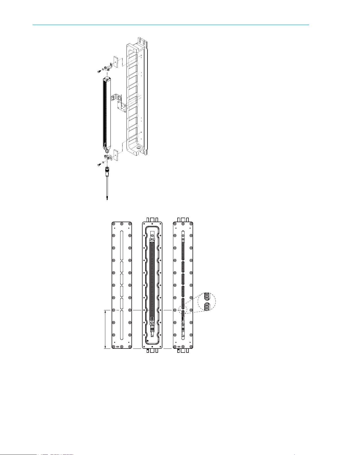
2. Attach the swivel mount brackets to the upper and lower end caps on the safety
light curtain.
3. Mount the mounting bracket onto the riser using the fixing screws supplied. Align
the mounting bracket with the two locating pins. Tighten the fixing screws with a
torque of 5 to 5.5 Nm.
4. Secure the mounting bracket about halfway along the safety light curtain using the
two sliding nuts so that the riser is behind the safety light curtain. Insert and handtighten the screws on the sliding nuts.
5. Position the safety light curtain in the explosion-proof enclosure so that the con‐
necting cable is at the same end of the explosion-proof enclosure as the 3/4" NPT
opening.
6. Using the fixing screws supplied, attach the swivel mount brackets and riser to the
mounting holes provided in the explosion-proof enclosure.
7. Tighten the fixing screws on the swivel mount brackets with a torque of 2.5 to 3
Nm. Too high a torque could damage the swivel mount brackets while too low a
torque does not provide sufficient protection against vibration.
10
O PE R AT I NG IN S TR U CT I ON S | C4000 Fusion Ex 8022867/2019-03-04 | SICK
Subject to change without notice
Page 11
1
2
MOUNTING 3
Figure 1: Mount the safety light curtain in the explosion-proof enclosure
Figure 2: Align the safety light curtain in the explosion-proof enclosure
Measure the distance from the end of the cover to the first rib.
1
Detailed view
2
8022867/2019-03-04 | SICK O P ER A TI N G I NS T RU C TI O NS | C4000 Fusion Ex
Subject to change without notice
11
Page 12

3 MOUN
TING
8. Align the safety light curtain in the explosion-proof enclosure so that it meets the
f
ollowing criteria:
Each rib in the window on the cover must cover no more than one optical
°
lens.
Depending on the protective field height, the first rib on the side of the con‐
°
nection must cover the following optical lenses:
Protective field height Optical lenses covered
600 mm Sixth optical lens
900 mm Second optical lens
1,200 mm Second optical lens
9. Tighten the screws used to secure the mounting bracket to the explosion-proof
enc
losure with a torque of 12 to 13 Nm.
10. Tighten the screws used to secure the mounting bracket to the safety light curtain
with a torque of 5 to 5.5 Nm.
11. Tighten the screws used to secure the safety light curtain in the swivel mount
brackets with a torque of 2.5 to 3 Nm.
12. Guide the connecting cable through the 3/4" NPT opening. Make sure that the
thread for the 3/4" NPT opening is not damaged.
13. If a cable gland is required, follow the instructions to mount the gland, see "Mount‐
ing the optional cable gland", page 12.
14. Fit the cover to the explosion-proof enclosure using the supplied fixing screws and
washers. Tighten the fixing screws with a torque of 11.5 to 14.5 Nm.
NOTE
he washers must be used to obtain enclosure rating IP 66.
T
3.3.2 Mounting the optional cable gland
Depending on national regulations and requirements, a cable gland may have to be
ins
talled. The cable gland is available as an accessory.
1. Guide the cable through the cable gland.
2. Screw the cable gland into the 3/4" NPT opening on the explosion-proof enclosure.
3. Pull the collar on the cable gland so that the cable is securely attached.
DANGER
k of ignition or explosion
Ris
Check the 3/4" NPT opening on the thread for damage.
b
Do not use the device if the thread for the 3/4" NPT opening is damaged.
b
3.3.3 Mounting the handles onto the cover of the explosion-proof enclosure
1. Use the supplied M6 screws to secure the two handles onto the cover of the explo‐
sion-pr
oof enclosure.
2. Tighten the screws with a torque of 4.5 to 5 Nm.
12
O PE R AT I NG IN S TR U CT I ON S | C4000 Fusion Ex 8022867/2019-03-04 | SICK
Subject to change without notice
Page 13

Figure 3: Mounting the two handles
MOUNTING 3
3.3.4 Mounting the safety light curtain
General notes
F
ind a place to mount the safety light curtain that is stable enough to hold its
b
weight.
Mount the sender and receiver on a level surface.
b
Mount the sender and receiver at the same height.
b
The end with the connecting cable must point in the same direction for both
b
devices.
Figure 4: The sender and receiver are mounted incorrectly
S
ender and receiver must not be installed at 180° rotated relative to each other.
b
Make sure that the sender and receiver are aligned correctly. The optical lens sys‐
b
tems of the sender and the receiver must be located opposite one another.
8022867/2019-03-04 | SICK O P ER A TI N G I NS T RU C TI O NS | C4000 Fusion Ex
Subject to change without notice
13
Page 14
4 x
4 x
WS
13
mm
Scope of delivery
Required tools
3 MOUN
TING
ssary, use a water level to check that the components are parallel.
If nece
b
The alignment bracket makes it possible to rotate the sender and receiver around
b
the axis of the device and to align them accurately, see "Aligning the sender and
receiver", page 21.
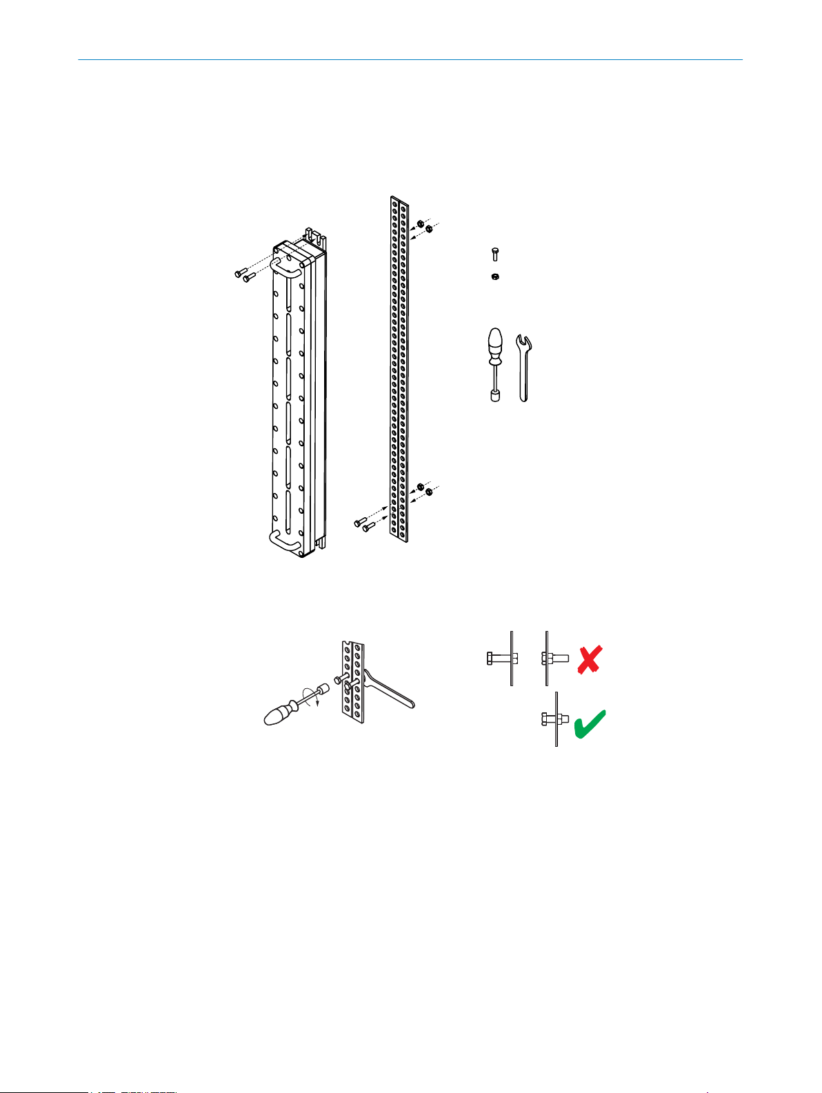
Mounting the safety light curtain without the alignment bracket
Figure 5: Mounting the safety light curtain without the alignment bracket
Use w
b
1. Using 6 to 8 revolutions, screw in the two M8 screws for mounting the lower end of
rench size 13 mm.
Figure 6: Mounting the safety light curtain without the alignment bracket: Step 1
he explosion-proof enclosure. Make sure you leave enough space between the
t
screws and the mounting surface for the lower end of the explosion-proof enclo‐
sure.
14
O PE R AT I NG IN S TR U CT I ON S | C4000 Fusion Ex 8022867/2019-03-04 | SICK
Subject to change without notice
Page 15

MOUNTING 3
Figure 7: Mounting the safety light curtain without the alignment bracket: Step 2
2. Position the explosion-proof enclosure on the two screws so that the mounting
hole
s are directly over the partly-tightened screws.
Figure 8: Mounting the safety light curtain without the alignment bracket: Steps 3 and 4
3. Fix the upper end of the explosion-proof enclosure to the mounting surface using
t
wo M8 screws.
4. Tighten the two lower M8 screws.
8022867/2019-03-04 | SICK O P ER A TI N G I NS T RU C TI O NS | C4000 Fusion Ex
Subject to change without notice
15
Page 16

2 x
Part no. 2072525
4 x
4 x
4 x
WS
13
mm
Scope of delivery
Required tools
3 MOUN
TING
Mounting the safety light curtain using the alignment brackets
Figure 9: Mounting the safety light curtain using the alignment brackets
16
Figure 10: Assembling the alignment brackets
O PE R AT I NG IN S TR U CT I ON S | C4000 Fusion Ex 8022867/2019-03-04 | SICK
Subject to change without notice
Page 17

MOUNTING 3
1. Mount the lower alignment bracket so that the threaded hole faces up and the
he
ad of the lock screw faces down.
2. Rotate the alignment bracket as far to one side as possible. Secure the alignment
bracket on the open side by screwing the first M8 screw into the through hole.
3. Rotate the lower alignment bracket to the other side. Secure the alignment
bracket using the second M8 screw.
4. Mount the upper alignment bracket so that the threaded hole faces down and the
head of the lock screw faces up.
5. Rotate the upper alignment bracket as far to one side as possible. Secure the
alignment bracket on the open side by screwing the first M8 screw into the
through hole.
6. Rotate the upper alignment bracket to the other side. Secure the alignment
bracket using the second M8 screw.
Figure 11: Mounting the safety light curtain using the alignment brackets: Steps 1 to 6
7. Using 6 to 8 revolutions, screw the two M8 screws for mounting the lower end of
t
he explosion-proof enclosure into the lower alignment bracket. Make sure you
leave enough space between the screws and the alignment bracket for the lower
end of the explosion-proof enclosure.
Figure 12: Mounting the safety light curtain using the alignment brackets: Step 7
8. Position the explosion-proof enclosure on the two screws so that the mounting
hole
s are directly over the partly-tightened screws.
8022867/2019-03-04 | SICK O P ER A TI N G I NS T RU C TI O NS | C4000 Fusion Ex
Subject to change without notice
17
Page 18

3 MOUN
TING
Figure 13: Mounting the safety light curtain using the alignment brackets: Step 8
9. Fix the upper end of the explosion-proof enclosure to the upper alignment bracket
usin
g two M8 screws.
10. Tighten the two lower screws.
18
Figure 14: Mounting the safety light curtain using the alignment brackets: Steps 9 and 10
11. Turn the safety light curtains so that they face one another and so that the
r
eceiver receives the strongest signal possible.
O PE R AT I NG IN S TR U CT I ON S | C4000 Fusion Ex 8022867/2019-03-04 | SICK
Subject to change without notice
Page 19

28 Nm to 28.5 Nm
28 Nm to 28.5 Nm
MOUNTING 3
Figure 15: Mounting the safety light curtain using the alignment brackets: Steps 11 and 12
12. Tighten the locking screws on all alignment brackets with a torque of 28 to 28.5
Nm in or
der to secure the safety light curtain in this position.
8022867/2019-03-04 | SICK O P ER A TI N G I NS T RU C TI O NS | C4000 Fusion Ex
Subject to change without notice
19
Page 20

4 ELECTRICAL INSTALLATION
4 Electrical installation
4.1 Safety
In addition to the information in the underlying operating instructions, please observe
he following points when installing the electrics for the safety light curtain.
t
DANGER
Ignit
ion Hazard
Failure to observe this information could result in a risk of ignition
Always switch the voltage supply off before disconnecting a connecting cable from
b
the device.
Ensure that all electrical connections to the device or to the connections are pro‐
b
tected.
The IP enclosure rating for the connections and therefore for the device is only
b
guaranteed if the connections are protected. Otherwise foreign objects can get
into the terminal compartment. This can cause an explosion the next time the
device is switched on.
Put in place measures for ensuring supply reliability and delivery dependability.
b
DANGER
Ris
k of ignition or explosion
If you have to remove the cover when working on the safety light curtain, make
b
sure that the joints and o-ring are clean and undamaged before refitting the cover.
DANGER
k of ignition or explosion
Ris
Disconnect the power supply before opening the explosion-proof enclosure to
b
avoid igniting hazardous atmospheres.
Do not reconnect the power supply until you have completed the electrical installa‐
b
tion.
DANGER
k of ignition or explosion
Ris
Each connection to the protection earth (PE) on the explosion-proof enclosure
b
must use at least one wire with a cross-section meeting the requirements of the
table below.
Table 1: Minimum wire cross-section for protection earth (PE)
Wire cross-section of outer cable S Minimum wire cross-section of the corre‐
g protection earth wire S
2
P
S ≤ 16 mm
16 mm2 < S
S > 35 mm
2
≤ 35 mm
2
spondin
S
2
16 mm
0.5 S
20
O PE R AT I NG IN S TR U CT I ON S | C4000 Fusion Ex 8022867/2019-03-04 | SICK
Subject to change without notice
Page 21

5 Aligning the sender and receiver
After mounting and electrical installation, the sender and receiver must be aligned with
ach other.
e
DANGER
D
angerous state of the machine
Make sure that the outputs of the safety light curtain have no effect on the
b
machine during the alignment process.
NOTE
Use t
he optional alignment bracket if the alignment cannot be adjusted when mounting
the safety light curtain directly.
Aligning using the alignment bracket
he alignment bracket can be used to adjust the safety light curtain as follows:
T
– Rotate (± 45°)
ALIGNING THE SENDER AND RECEIVER 5
Figure 16: Rotating with the alignment bracket
Aligning the sender and receiver with one another
Ho
w to align the sender and receiver using the alignment bracket:
Pay attention to the mounting heights of the sender and receiver. Both devices
b
must be mounted at the same height.
Provide a rectangular protective field. The sender and receiver must be mounted
b
parallel to one another.
Switch on the power supply to the safety light curtain.
b
Rotate the sender to align the sender to the receiver.
b
Rotate the receiver to align the receiver to the sender.
b
8022867/2019-03-04 | SICK O P ER A TI N G I NS T RU C TI O NS | C4000 Fusion Ex
Subject to change without notice
21
Page 22

5 ALIGNIN
G THE SENDER AND RECEIVER
ollow the alignment instructions in the underlying operating instructions.
F
b
Once the sender and receiver are aligned correctly, secure the components in the
b
alignment brackets with a torque of 28 to 28.5 Nm.
Switch the power supply off and then on again.
b
Check the alignment quality display as described in the underlying operating
b
instructions to make sure that components are still correctly aligned with one
another.
22
O PE R AT I NG IN S TR U CT I ON S | C4000 Fusion Ex 8022867/2019-03-04 | SICK
Subject to change without notice
Page 23

6 Maintenance
DANGER
Ris
k of ignition or explosion
b
b
DANGER
Risk of ignition or explosion
b
DANGER
k of ignition or explosion
Ris
b
MAINTENANCE 6
Disconnect the voltage supply before any maintenance work is carried out to avoid
igniting hazardous atmospheres.
Only reconnect the voltage supply once you have completed the maintenance
work.
If you have to remove the cover when working on the safety light curtain, make
sure that the joints and o-ring are clean and undamaged before refitting the cover.
Use fixing screws with a yield point of at least 640 MPa to attach the cover to the
explosion-proof enclosure.
The safety light curtain is maintenance-free. Depending on the ambient conditions, reg‐
ular c
6.1 Regular cleaning
DANGER
k of ignition or explosion
Ris
Static discharge could cause explosions in hazardous atmospheres.
Always use anti-static cleaning agents to prevent static charge.
b
Do not clean the device using a dry cloth.
b
NOTICE
D
b
Do not use any abrasive cleaning agents.
b
Do not use any oil-based cleaning agents.
b
We recommend anti-static cleaning agents.
b
Clean the front screen.
Use a clean, soft brush to remove dust from the front screen.
1.
2. Then wipe the front screen with a clean, damp cloth.
3. Check the position of the sender and receiver after cleaning.
4. Check the effectiveness of the protective device. You will find information on how
to check the effectiveness in the underlying operating instructions.
leaning is required.
o not use any aggressive cleaning agents.
8022867/2019-03-04 | SICK O P ER A TI N G I NS T RU C TI O NS | C4000 Fusion Ex
Subject to change without notice
23
Page 24

7 TECHNICAL DATA
7 Technical data
7.1 Data sheet
NOTE
T
he following table only contains details on the safety light curtain that are not included
in the underlying operating instructions.
Table 2: General system data
Protective field height, depending on
ype
t
Resolution (detection capability) 20 mm
Protective field width 0 m … 15.9 m 0 m … 17.6 m
Enclosure rating (EN 60529) IP 66
Equipment group/category II
Weight Depending on the protective field height, see "T
1)
If you are using the full protective field width, check to see if the orange LED lights up (cleaning or align‐
ment nece
2)
In order to achieve enclosure rating IP 66, washers must be used for the fixing screws on the enclosure
cover.
Minimum Typical Maximum
600, 900, and 1,200 mm
1)
2)
X II 2 G Ex db IIB T6 Gb
X II 2 D Ex tb IIIC T56°C Db
Ex db IIB T6
Ex tb IIIC T56°C Db IP6X
able of
weights", page 24
ssary). The system still has a reserve of 30 %.
7.2 Table of weights
Table 3: Weight of sender and receiver
Protective field height [mm] Weight [kg]
600 29.92 29.95
900 38.57 38.6
1200 47.22 47.25
1)
Tolerance: ± 50 g.
1)
s S
ender r Receiver
24
O PE R AT I NG IN S TR U CT I ON S | C4000 Fusion Ex 8022867/2019-03-04 | SICK
Subject to change without notice
Page 25

7.3 Dimensional drawings
177,6267,4
6,4
9,5
67,5
58,7
161,8
89,6
44,5
1.100,2
1.068,2
1.035
142,1
50,8
TECHNICAL DATA 7
Figure 17: Dimensional drawing, sender and receiver, protective field height 600 mm
8022867/2019-03-04 | SICK O P ER A TI N G I NS T RU C TI O NS | C4000 Fusion Ex
Subject to change without notice
25
Page 26

252,4
192,6
1.400,2
1.368,2
1.335
6,4
9,5
67,5
58,7
161,8
89,6
44,5
142,1
50,8
7 T
ECHNICAL DATA
Figure 18: Dimensional drawing, sender and receiver, protective field height 900 mm
26
O PE R AT I NG IN S TR U CT I ON S | C4000 Fusion Ex 8022867/2019-03-04 | SICK
Subject to change without notice
Page 27

6,4
9,5
67,5
58,7
161,8
89,6
44,5
1.700,2
1.668,2
1.635
237,7 206,9
50,8
142,1
TECHNICAL DATA 7
Figure 19: Dimensional drawing, sender and receiver, protective field height 1,200 mm
8022867/2019-03-04 | SICK O P ER A TI N G I NS T RU C TI O NS | C4000 Fusion Ex
Subject to change without notice
27
Page 28

8 ORDERING INFORMATION
8 Ordering information
8.1 Scope of delivery
Scope of delivery, sender
C4000 F
•
Explosion-proof enclosure
•
2 swivel mount brackets
•
2 handles
•
30 m system connection cables, flying leads
•
Scope of delivery, receiver
C4000 Fusion receiver without extension connection
•
Explosion-proof enclosure
•
2 swivel mount brackets
•
2 handles
•
30 m system connection cables, flying leads
•
Test rod with diameter corresponding to the physical resolution of the safety light
•
curtain
Operating instructions on CD-ROM
•
CDS (Configuration & Diagnostic Software) on CD-ROM
•
usion sender without extension connection
8.2 Ordering information C4000 Fusion Ex
Table 4: Ordering information C4000 Fusion Ex
Protective field
height [mm]
600 1097726 EXS-06C6202A020 1097725 EXE-06C6202A020 1097724 EXP-06C6202A020
900 1097729 EXS-09C6402A020 1097728 EXE-09C6402A020 1097727 EXP-09C6402A020
1200 1097732 EXS-12C6602A020 1097731 EXE-12C6602A020 1097730 EXP-12C6602A020
Part number Type code Part number Type code Part number Type code
s S
ender r Receiver s r Sender and receiver
28
O PE R AT I NG IN S TR U CT I ON S | C4000 Fusion Ex 8022867/2019-03-04 | SICK
Subject to change without notice
Page 29

9 Accessories
3,6
41
14,5
8,5
43,5
59
62
Ø 30,6
75
37,5
15
7
Ø 8,4
30
8
2225
69
22,5
24
7,5
90,5
15,1
36,1
5
50
±1
44
±1
25
12
14
24
5,3
±0,1
Ø 8,3
±0,1
4,8
9.1 Brackets
Part Part number
2 swivel mount brackets, 2 risers, 1 mounting bracket with riser
included with delivery)
(
2 alignment brackets for the explosion-proof enclosure 2072525
Swivel mount bracket with mounting bracket and risers
ACCESSORIES 9
2074626
Figure 20: Dimensional drawing, swivel mount bracket with riser (2074626)
Figure 21: Dimensional drawing, mounting bracket with riser (2074626)
8022867/2019-03-04 | SICK O P ER A TI N G I NS T RU C TI O NS | C4000 Fusion Ex
Subject to change without notice
29
Page 30

95,3
56,2 80
9 ACCESSORIES
9.2 Connectivity
Alignment bracket
Figure 22: Dimensional drawing, alignment bracket (2072525)
Table 5: Ordering information for connecting cable 1) M26, 12-pin (0.75 mm 2)
Part Part number
DOL-0612G2M5075KM0, female connector, straight with 2.5 m cable,
f
lying leads
DOL-0612G05M075KM0, female connector, straight with 5 m cable,
flying leads
DOL-0612G7M5075KM0 female connector, straight with 7.5 m cable,
lying leads
f
DOL-0612G10M075KM0, female connector, straight with 10 m cable,
flying leads
DOL-0612G15M075KM0, female connector, straight, with 15 m cable,
flying leads
DOL-0612G20M075KM0 female connector, straight with 20 m cable,
lying leads
f
DOL-0612G30M075KM0 female connector, straight with 30 m cable,
flying leads
DOL-0612G50MD75KM0, female connector, straight, with 50 m cable,
lying leads
f
1)
Ambient operating temperature: Down to −30° C with fixed installation.
Table 6: Order information for cable (ready to assemble)
Part Part number
Per meter, max. 100 m, 12-wire (0.75 mm2) 6021437
2022544
2022545
2022546
2022547
2022548
2022549
2022550
2033548
30
O PE R AT I NG IN S TR U CT I ON S | C4000 Fusion Ex 8022867/2019-03-04 | SICK
Table 7: Ordering information for cable gland
Part Part number
Cable gland for the European market 5329002
The following accessories can only be used outside the explosion-hazardous area
Subject to change without notice
Page 31

Table 8: Ordering information for power supply
Part Type code Part number
Output 24 V DC, 50 W (2.1 A), voltage supply
NE
120 V … 240 V AC
Output 24 V DC, 95 W (3.9 A), voltage supply
NEC Class 2, SELV, PELV, input
100 V … 120 V/220 V … 240 V AC
9.3 Alignment aid
The following accessories can only be used outside the explosion-hazardous area
Part Part number
Laser alignment aid AR60 1015741
Adapter 2074849
ACCESSORIES 9
PS50WE24V 7028789
C Class 2, SELV, PELV, input
PS95WE24V 7028790
8022867/2019-03-04 | SICK O P ER A TI N G I NS T RU C TI O NS | C4000 Fusion Ex
Subject to change without notice
31
Page 32

10 ANNE
X
10 Annex
10.1 Compliance with EU directives
EU declaration of conformity (extract)
he undersigned, representing the manufacturer, herewith declares that the product is
T
in conformity with the provisions of the following EU directive(s) (including all applicable
amendments), and that the standards and/or technical specifications stated in the EU
declaration of conformity have been used as a basis for this.
Complete EU declaration of conformity for download
You can call up the EU declaration of conformity and the current operating instructions
for the protective device by entering the part number in the search field at
www.sick.com (part number: see the type label entry in the “Ident. no.” field).
32
O PE R AT I NG IN S TR U CT I ON S | C4000 Fusion Ex 8022867/2019-03-04 | SICK
Subject to change without notice
Page 33

11 List of figures
1. Mount the safety light curtain in the explosion-proof enclosure.............................11
2. Align the safety light curtain in the explosion-proof enclosure................................11
3. Mounting the two handles......................................................................................... 13
4. The sender and receiver are mounted incorrectly....................................................13
5. Mounting the safety light curtain without the alignment bracket........................... 14
6. Mounting the safety light curtain without the alignment bracket: Step 1.............. 14
7. Mounting the safety light curtain without the alignment bracket: Step 2.............. 15
8. Mounting the safety light curtain without the alignment bracket: Steps 3 and 4..15
9. Mounting the safety light curtain using the alignment brackets.............................16
10. Assembling the alignment brackets..........................................................................16
11. Mounting the safety light curtain using the alignment brackets: Steps 1 to 6...... 17
12. Mounting the safety light curtain using the alignment brackets: Step 7................17
13. Mounting the safety light curtain using the alignment brackets: Step 8................18
14. Mounting the safety light curtain using the alignment brackets: Steps 9 and 10.18
15. Mounting the safety light curtain using the alignment brackets: Steps 11 and 12
16. Rotating with the alignment bracket......................................................................... 21
17. Dimensional drawing, sender and receiver, protective field height 600 mm.........25
18. Dimensional drawing, sender and receiver, protective field height 900 mm.........26
19. Dimensional drawing, sender and receiver, protective field height 1,200 mm......27
20. Dimensional drawing, swivel mount bracket with riser (2074626)........................ 29
21. Dimensional drawing, mounting bracket with riser (2074626).............................. 29
22. Dimensional drawing, alignment bracket (2072525)..............................................30
LIST OF FIGURES 11
.....................................................................................................................................
19
8022867/2019-03-04 | SICK O P ER A TI N G I NS T RU C TI O NS | C4000 Fusion Ex
Subject to change without notice
33
Page 34

12 LIS
T OF TABLES
12 List of tables
1. Minimum wire cross-section for protection earth (PE).............................................20
2. General system data.................................................................................................. 24
3. Weight of sender and receiver...................................................................................24
4. Ordering information C4000 Fusion Ex.....................................................................28
5. Ordering information for connecting cable M26, 12-pin (0.75 mm 2)....................
6. Order information for cable (ready to assemble)......................................................30
7. Ordering information for cable gland........................................................................ 30
8. Ordering information for power supply...................................................................... 31
30
34
O PE R AT I NG IN S TR U CT I ON S | C4000 Fusion Ex 8022867/2019-03-04 | SICK
Subject to change without notice
Page 35

LIST OF TABLES 12
8022867/2019-03-04 | SICK O P ER A TI N G I NS T RU C TI O NS | C4000 Fusion Ex
Subject to change without notice
35
Page 36

Further locations at www.sick.com
Australia
Phone +61 (3) 9457 0600
1800 33 48 02 – tollfree
E-Mail sales@sick.com.au
Austria
Phone +43 (0) 2236 62288-0
E-Mail office@sick.at
Belgium/Luxembourg
Phone +32 (0) 2 466 55 66
E-Mail info@sick.be
Brazil
Phone +55 11 3215-4900
E-Mail comercial@sick.com.br
Canada
Phone +1 905.771.1444
E-Mail cs.canada@sick.com
Czech Republic
Phone +420 2 57 91 18 50
E-Mail sick@sick.cz
Chile
Phone +56 (2) 2274 7430
E-Mail chile@sick.com
China
Phone +86 20 2882 3600
E-Mail info.china@sick.net.cn
Denmark
Phone +45 45 82 64 00
E-Mail sick@sick.dk
Finland
Phone +358-9-25 15 800
E-Mail sick@sick.fi
France
Phone +33 1 64 62 35 00
E-Mail info@sick.fr
Germany
Phone +49 (0) 2 11 53 01
E-Mail info@sick.de
Hong Kong
Phone +852 2153 6300
E-Mail ghk@sick.com.hk
Hungary
Phone +36 1 371 2680
E-Mail ertekesites@sick.hu
India
Phone +91-22-6119 8900
E-Mail info@sick-india.com
Israel
Phone +972-4-6881000
E-Mail info@sick-sensors.com
Italy
Phone +39 02 27 43 41
E-Mail info@sick.it
Japan
Phone +81 3 5309 2112
E-Mail support@sick.jp
Malaysia
Phone +603-8080 7425
E-Mail enquiry.my@sick.com
Mexico
Phone +52 (472) 748 9451
E-Mail mario.garcia@sick.com
Netherlands
Phone +31 (0) 30 229 25 44
E-Mail info@sick.nl
New Zealand
Phone +64 9 415 0459
0800 222 278 – tollfree
E-Mail sales@sick.co.nz
Norway
Phone +47 67 81 50 00
E-Mail sick@sick.no
Poland
Phone +48 22 539 41 00
E-Mail info@sick.pl
Romania
Phone +40 356-17 11 20
E-Mail office@sick.ro
Russia
Phone +7 495 283 09 90
E-Mail info@sick.ru
Singapore
Phone +65 6744 3732
E-Mail sales.gsg@sick.com
Slovakia
Phone +421 482 901 201
E-Mail mail@sick-sk.sk
Slovenia
Phone +386 591 78849
E-Mail office@sick.si
South Africa
Phone +27 (0)11 472 3733
E-Mail info@sickautomation.co.za
South Korea
Phone +82 2 786 6321
E-Mail info@sickkorea.net
Spain
Phone +34 93 480 31 00
E-Mail info@sick.es
Sweden
Phone +46 10 110 10 00
E-Mail info@sick.se
Switzerland
Phone +41 41 619 29 39
E-Mail contact@sick.ch
Taiwan
Phone +886-2-2375-6288
E-Mail sales@sick.com.tw
Thailand
Phone +66 2 645 0009
E-Mail marcom.th@sick.com
Turkey
Phone +90 (216) 528 50 00
E-Mail info@sick.com.tr
United Arab Emirates
Phone +971 (0) 4 88 65 878
E-Mail info@sick.ae
United Kingdom
Phone +44 (0)17278 31121
E-Mail info@sick.co.uk
USA
Phone +1 800.325.7425
E-Mail info@sick.com
Vietnam
Phone +65 6744 3732
E-Mail sales.gsg@sick.com
8022867/2019-03-04/en
SICK AG | Waldkirch | Germany | www.sick.com
 Loading...