

Page 1
WLA16 Bluetooth®
O P E R A T I N G I N S T R U C T I O N S
Page 2
WLA16 Bluetooth®
O P E R A T I N G I N S T R U C T I O N S
de
en
es
fr
it
ja
pt
ru
zh
Page 3
Described product
WLA16 - Bluetooth®
Manufacturer
SICK AG
Erwin-Sick-Str. 1
79183 Waldkirch
Germany
Legal information
This work is protected by copyright. Any rights derived from the copyright shall be
reserved for SICK AG. Reproduction of this document or parts of this document is only
permissible within the limits of the legal determination of Copyright Law. Any modifica‐
tion, abridgment or translation of this document is prohibited without the express writ‐
ten permission of SICK AG.
The trademarks stated in this document are the property of their respective owner.
© SICK AG. All rights reserved.
Original document
This document is an original document of SICK AG.
2
8022690.10DR | SICK
Subject to change without notice
Page 4

Contents
CONTENTS
1 Safety information............................................................................ 4
1.1 General safety notes................................................................................ 4
1.2 Notes on UL approval............................................................................... 4
2 Intended use...................................................................................... 4
3 Operating and status indicators...................................................... 4
4 Mounting............................................................................................. 5
5 Electrical installation........................................................................ 5
6 Commissioning.................................................................................. 7
7 Troubleshooting................................................................................. 10
7.1 ................................................................................................................... 10
8 Disassembly and disposal............................................................... 11
9 Maintenance...................................................................................... 11
10 Approvals............................................................................................ 12
10.1 Bluetooth® approvals............................................................................... 12
11 Technical data.................................................................................... 12
11.1 Technical data........................................................................................... 12
11.2 Bluetooth technical data®....................................................................... 13
8022690.10DR | SICK
Subject to change without notice
3
Page 5
2006/42/EC
NO
SAFETY
20
Ø 12,9
Ø 4,1
39,9
55,4
45,5
5
42
29,9
6
3
6,5
15
27,8
7,7
7,8
7,2
35,5
4,1
8,3
55,7
3
2
34,5
1
4
65
20
M12
18
Ø 4,1
39,9
55,4
55,7
45,5 5
7
42
29,9
52,9
6
17,5
3
6,5
15
28
7,5
35,5
4,1
3
2
34,5
1
4
65
1 SAFETY INFORMATION
1 Safety information
1.1 General safety notes
■
Read the operating instructions before commissioning.
■
specialists.
■
■
■
These operating instructions contain information required during the life cycle of
the sensor.
1.2 Notes on UL approval
Connection, mounting, and configuration may only be performed by trained
Not a safety component in accordance with the EU Machinery Directive.
When commissioning, protect the device from moisture and contamination.
The device must be supplied by a Class 2 source of supply.
UL Environmental Rating: Enclosure type 1
2 Intended use
The WLA16 Bluetooth is an opto-electronic photoelectric retro-reflective sensor
(referred to as “sensor” in the following) for the optical, non-contact detection of
objects, animals, and persons. A reflector is required for this product to function. If the
product is used for any other purpose or modified in any way, any warranty claim
against SICK AG shall become void.
3 Operating and status indicators
4
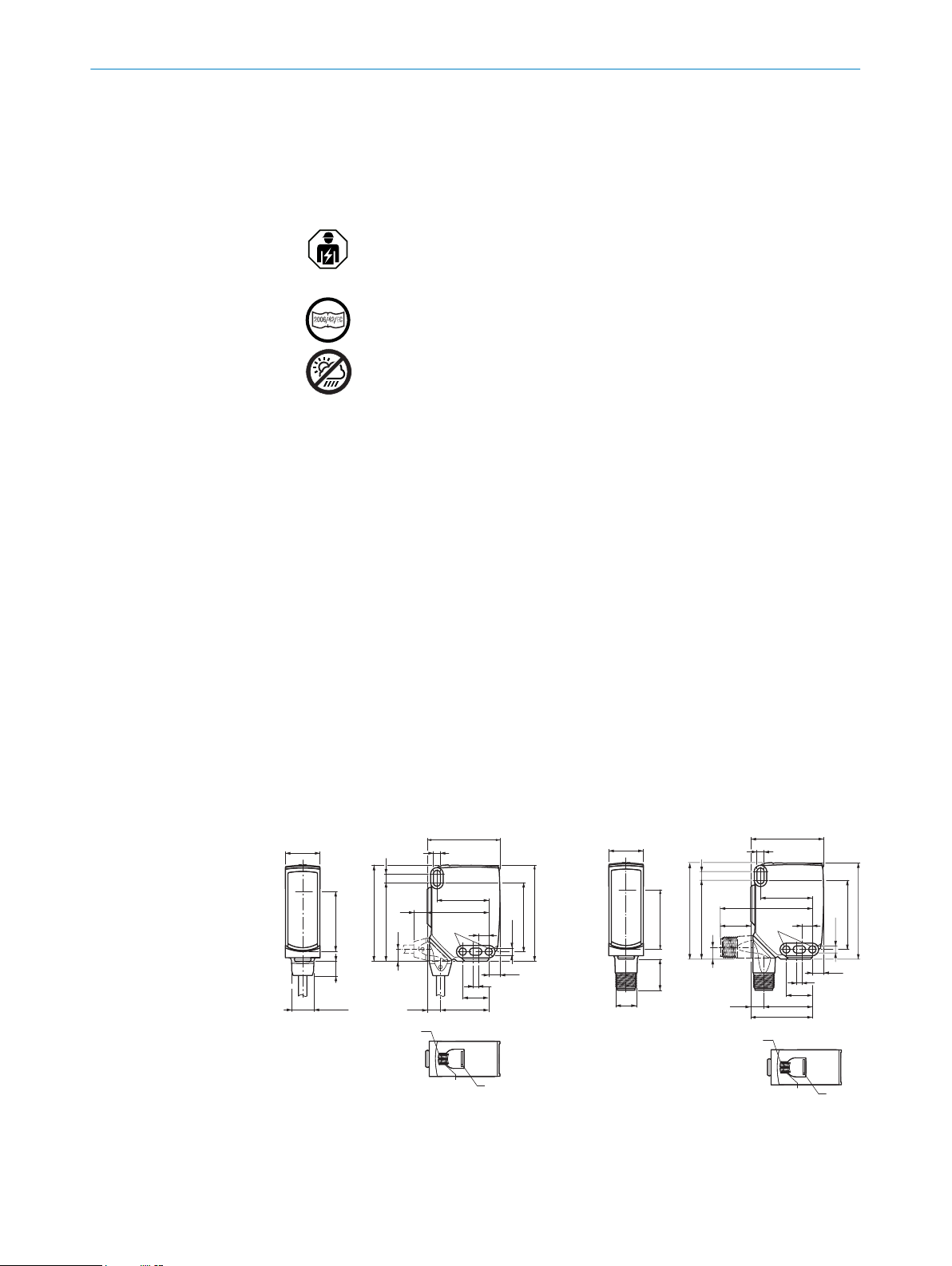
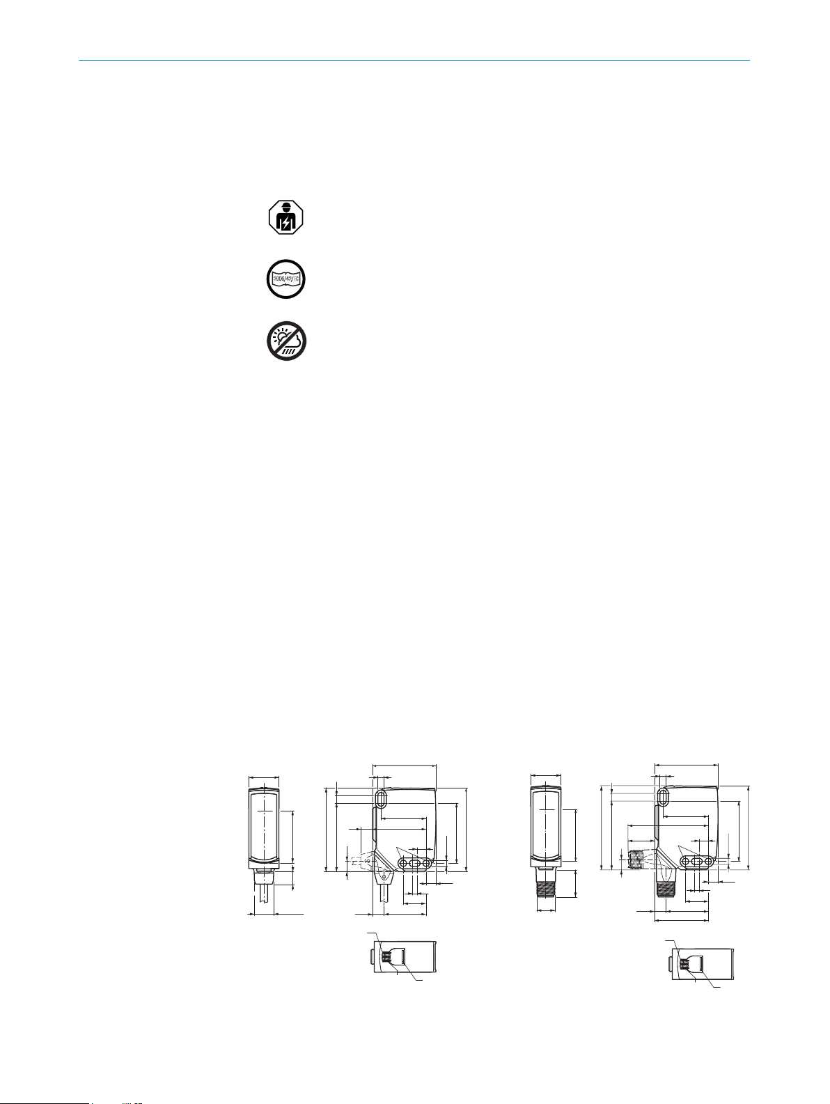
Figure 1: Dimensional drawing 1, cable
Center of optical axis
1
Fixing hole, Ø 4.1 mm
2
Connection
3
Figure 2: Dimensional drawing 2, male con‐
nector
8022690.10DR | SICK
Subject to change without notice
Page 6
LED indicator green: Supply voltage
1
2
4 3
1
2
4 3
1
2
4 3
4
active
LED indicator yellow: Status of
5
received light beam
BluePilot blue: Alignment aid
6
4 Mounting
Mount the sensor and the reflector using suitable mounting brackets (see the SICK
range of accessories). Align the sensor and reflector with each other.
Note the sensor's maximum permissible tightening torque of < 1,3 Nm.
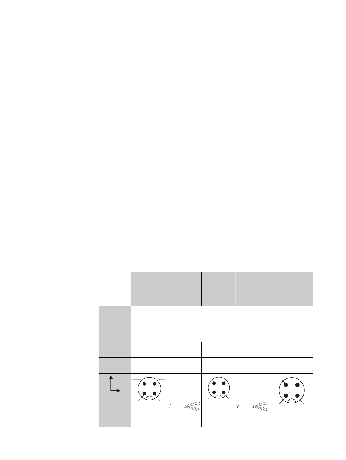
5 Electrical installation
The sensors must be connected in a voltage-free state (UV = 0 V). The following informa‐
tion must be observed, depending on the connection type:
– Male connector connection: Note pin assignment
– Cable: wire color
Only apply voltage/switch on the voltage supply (UV > 0 V) once all electrical connec‐
tions have been established.
MOUNTING 4
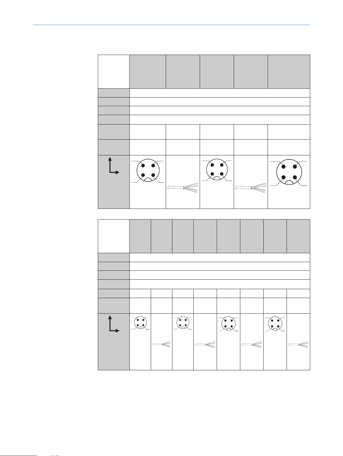
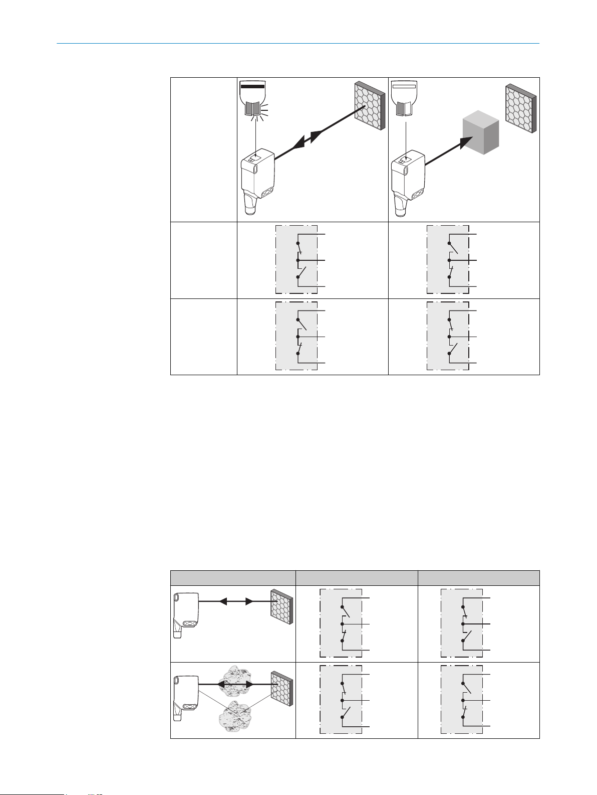
Explanations of the connection diagram (table 1- table 2)
Alarm = alarm output (table 4)
Health = alarm output (table 4)
MF (pin 2 configuration) = external input, teach-in, switching signal
QL1/C = switching output, IO-Link communication
DC: 10 ... 30 V DC
Table 1: DC
WLA16 -24162xxxA00
-34162xxxA00
1 + (L+)
2 MF
3 - (M)
4 QL1/C
Default: MF
Default:
QL1/C
Q Q
Q Q
-1x162xxxA00-24161xxxA0
0
-34161xxxA0
0
Q Q www.sick.com
Q Q
1 = brn
2 = wht
3 = blu
4 = blk
-1x161xxxA00-2416xxxxA01-
1 = brn
2 = wht
3 = blu
4 = blk
A99
-3416xxxxA01A99
8022709
www.sick.com
8022709
8022690.10DR | SICK
Subject to change without notice
0.14 mm
AWG26
2
0.14 mm
2
AWG26
5
Page 7
1
2
4 3
1
2
4 3
1
2
4 3
1
2
4 3
+ (L+)
Q
‒ (M)
+ (L+)
Q
‒ (M)
+ (L+)
Q
‒ (M)
+ (L+)
Q
‒ (M)
ELECTRICAL INSTALLATION
5
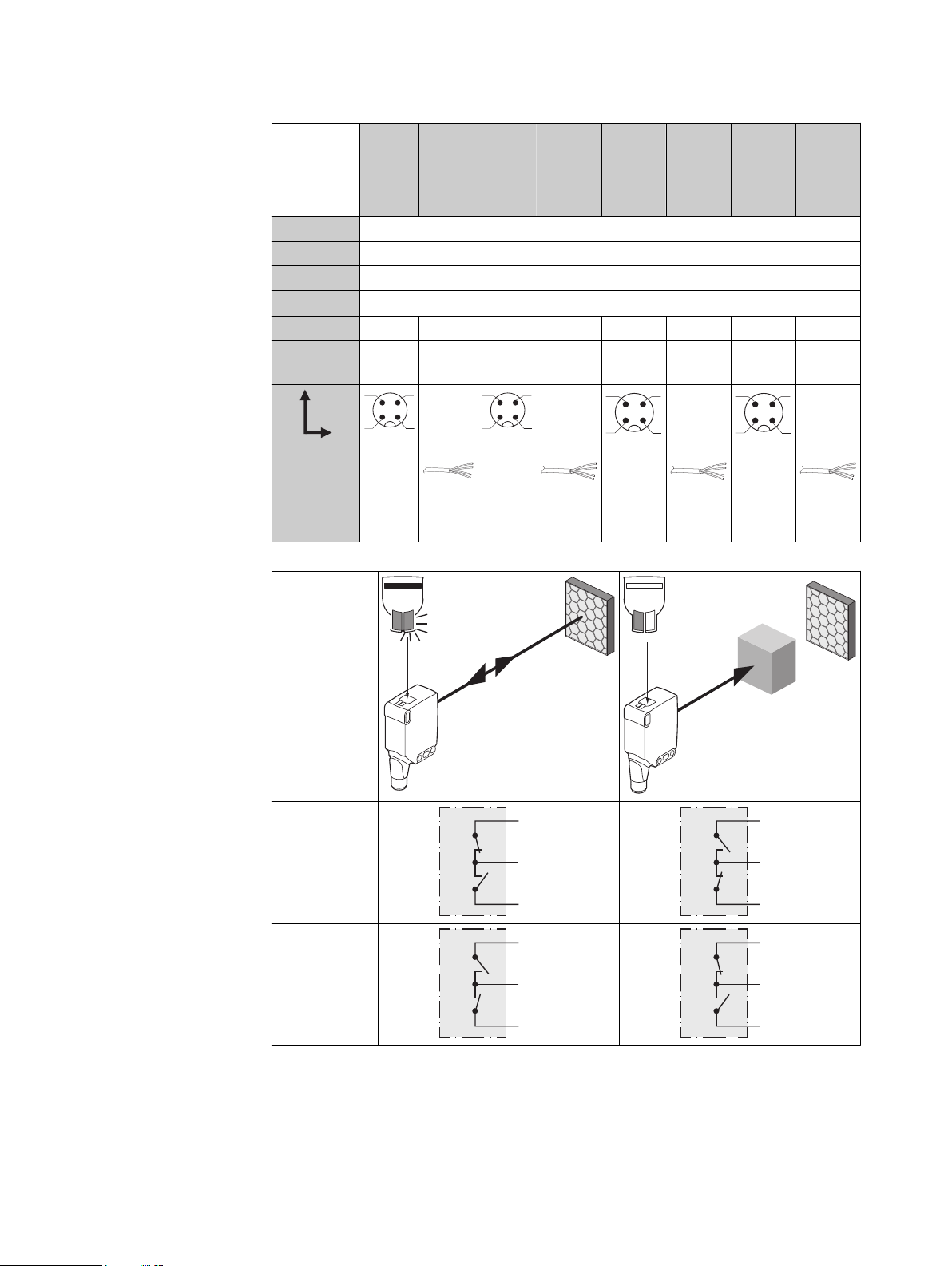
Table 2: DC
WLA16 -24165
xxxA00
-1x165
xxxA00
-24163
xxxA00
-1x163x
xxA00
-24166x
xxA00
-1x166x
xxA00
-24164x
xxA00
-1x164x
xxA00
-34165
xxxA00
-34163
xxxA00
-34166x
xxA00
-34164x
xxA00
1 + (L+)
2 MF
3 - (M)
4 QL1/C
Default: MF Alarm Alarm Alarm Alarm Health Health Health Health
Default:
Q Q
Q Q
Q Q
Q Q
QL1/C
1 = brn
2 = wht
3 = blu
4 = blk
0.14 m
2
m
AWG26
1 = brn
2 = wht
3 = blu
4 = blk
0.14 m
2
m
AWG26
1 = brn
2 = wht
3 = blu
4 = blk
0.14 m
2
m
AWG26
1 = brn
2 = wht
3 = blu
4 = blk
0.14 m
AWG26
Table 3: Push/pull
2
m
Q
Push-pull
(≤ 100 mA)
Q
Push-pull
(≤ 100 mA)
Alarm
Alarm output: The sensor (WLA16 Bluetooth) features a pre-failure notification output
(“Alarm” in connection diagram table 4), which issues a notification if the sensor is only
ready for operation to a limited extent. The LED indicator flashes in this case. Possible
causes: Sensor or reflector is contaminated, sensor is out of alignment. In the good
6
state: LOW (0), if excessively contaminated HIGH (1).
8022690.10DR | SICK
Subject to change without notice
Page 8

+ (L+)
Alarm
‒ (M)
+ (L+)
Health
‒ (M)
+ (L+)
Alarm
‒ (M)
+ (L+)
Health
‒ (M)
COMMISSIONING 6
Health
Health output: The sensor (WLA16 Bluetooth) features a pre-failure notification output
(“Health” in connection diagram table 4), which issues a notification if the sensor is
only ready for operation to a limited extent or the cable has been interrupted. Possible
causes: Sensor or reflector is contaminated, sensor is out of alignment, cable is dam‐
aged. In the good state: HIGH (1), if excessively contaminated or in the event of cable
interruption LOW (0). The yellow LED indicator flashes in this case.
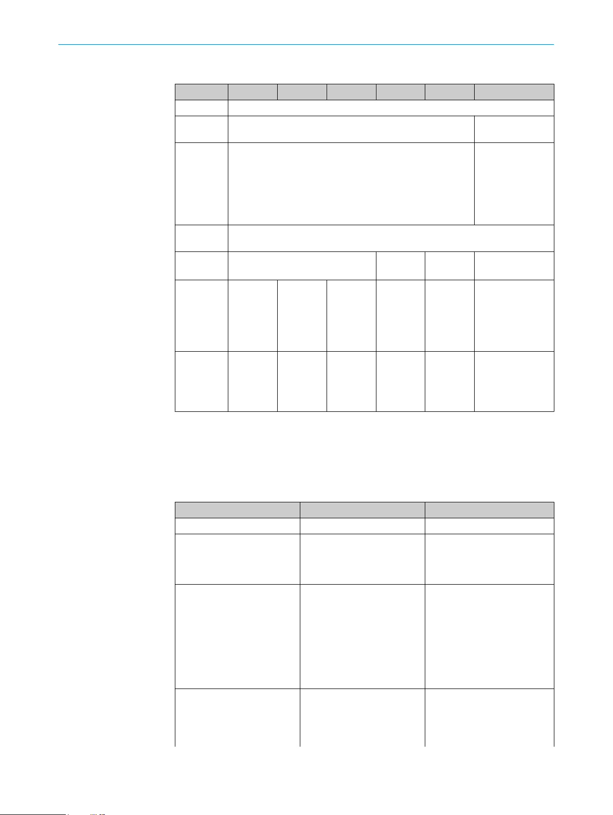
Table 4: Alarm / Health
Alarm (≤ 100 mA) Health (≤100 mA)
6 Commissioning
Bluetooth® is switched on for initial commissioning. You can get SOPASair in the Google
PlayStore (Android) and in the App Store (iOS).
Operating system requirements: Android version 6.0, most current version of iOS.
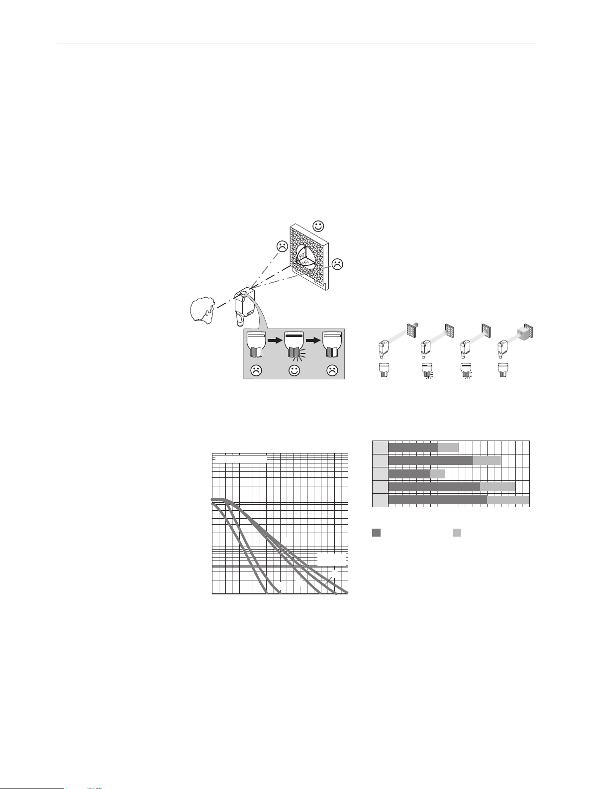
1 Alignment
Align the sensor with a suitable reflector. Select the position so that the red emitted light
beam hits the center of the reflector. The sensor must have a clear view of the reflector,
with no object in the path of the beam [see figure 3]. You must ensure that the optical
openings of the sensor and reflector are completely clear.
8022690.10DR | SICK
Subject to change without notice
Figure 3: Alignment 1 Figure 4: Alignment 2
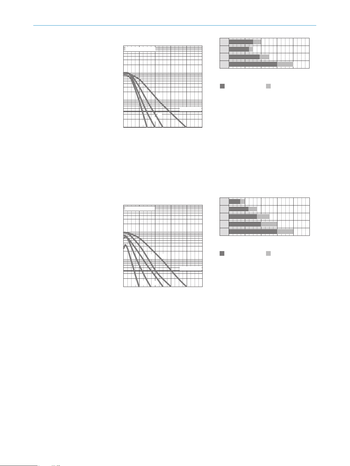
2 Sensing range
Adjust the distance between the sensor and the reflector according to the corresponding
diagram [see figure 5] (x = sensing range, y = operating reserve).
7
Page 9

0
1,000
100
10
1
2
(6.56)4(13.12)
10
(32.81)
8
(26.25)
6
(19.69)
Function reserve
Distance in m (feet)
4
2
1
3
5
Sensing range
WLA16P-xxxxx1xx
Sensing range Sensing range typ. max.
1
2
3
4
5
0
3.5 50
6 80
3 4
0
6.5 9
0
7 10
0
8
(26.25)
Distance in m (feet)
2
(6.56)
6
(19.69)
10
(32.81)
4
(13.12)
0
100
10
1
3
2
1
1,000
2
(6.56)4(13.12)
10
(32.81)
8
(26.25)
6
(19.69)
Function reserve
Distance in m (feet)
Sensing range
WLA16P-xxxxx1xx
1
2
3
0
0
1 2
0
1.8 3
0
4.5 6
0
Sensing range Sensing range typ. max.
8
(26.25)
Distance in m (feet)
2
(6.56)
6
(19.69)
10
(32.81)
4
(13.12)
6 COMMISSIONING
Figure 5: Characteristic line 1: Standard
reflector
Reflector PL22
1
Reflector P250, PL30A
2
Reflector PL20A
3
Reflector PL40A
4
Reflector PL80A, C110A
5
Figure 6: Bar graph 1: Standard reflector
Reflector PL22
1
Reflector P250, PL30A
2
Reflector PL20A
3
Reflector PL40A
4
Reflector PL80A, C110A
5
8
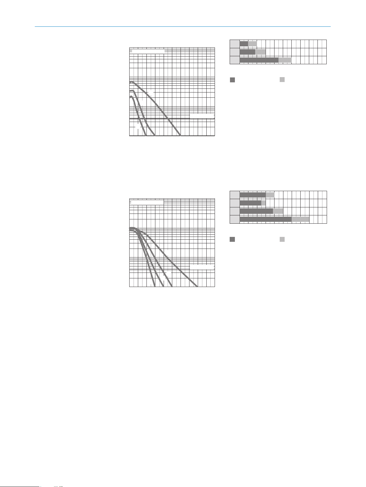
Figure 8: Bar graph 2: Reflective tape
Reflective tape REF-DG (50 x
1
50 mm)
Reflective tape REF-IRF-56 (50 x
2
50 mm)
Reflective tape REF-AC1000 (50 x
3
50 mm)
Figure 7: Characteristic line 2: Reflective
tape
Reflective tape REF-DG
1
Reflective tape REF-IRF-56
2
Reflective tape REF-AC1000
3
8022690.10DR | SICK
Subject to change without notice
Page 10
1,000
100
10
1
4
3
1
2
0
2
(6.56)4(13.12)
10
(32.81)
8
(26.25)
6
(19.69)
Function reserve
Distance in m (feet)
Sensing range
WLA16P-xxxxx1xx
Figure 9: Characteristic line 3: Fine triple
1
2
3
4
0
0
3 4
0
2.5 3
0
3.8 5
0
6 8
0
Sensing range Sensing range typ. max.
8
(26.25)
Distance in m (feet)
2
(6.56)
6
(19.69)
10
(32.81)
4
(13.12)
0
1,000
100
10
1
2
(6.56)4(13.12)
10
(32.81)
8
(26.25)
6
(19.69)
Function reserve
Distance in m (feet)
5
4
3
21
Sensing range
WLA16P-xxxxx1xx
Sensing range Sensing range typ. max.
1
2
3
4
5
0
0 8
(26.25)
1.4 2
0
2.4 3.5
0
3.5 5
0
4 6
0
6 8
0
Distance in m (feet)
2
(6.56)
6
(19.69)
10
(32.81)
4
(13.12)
reflectors
Reflector PL10FH-1
1
Reflector PL10F
2
Reflector PL20F
3
Reflector P250F
4
COMMISSIONING 6
Figure 10: Bar graph 3: Fine triple reflec‐
tors
Reflector PL10FH-1
1
Reflector PL10F
2
Reflector PL20F
3
Reflector P250F
4
8022690.10DR | SICK
Subject to change without notice
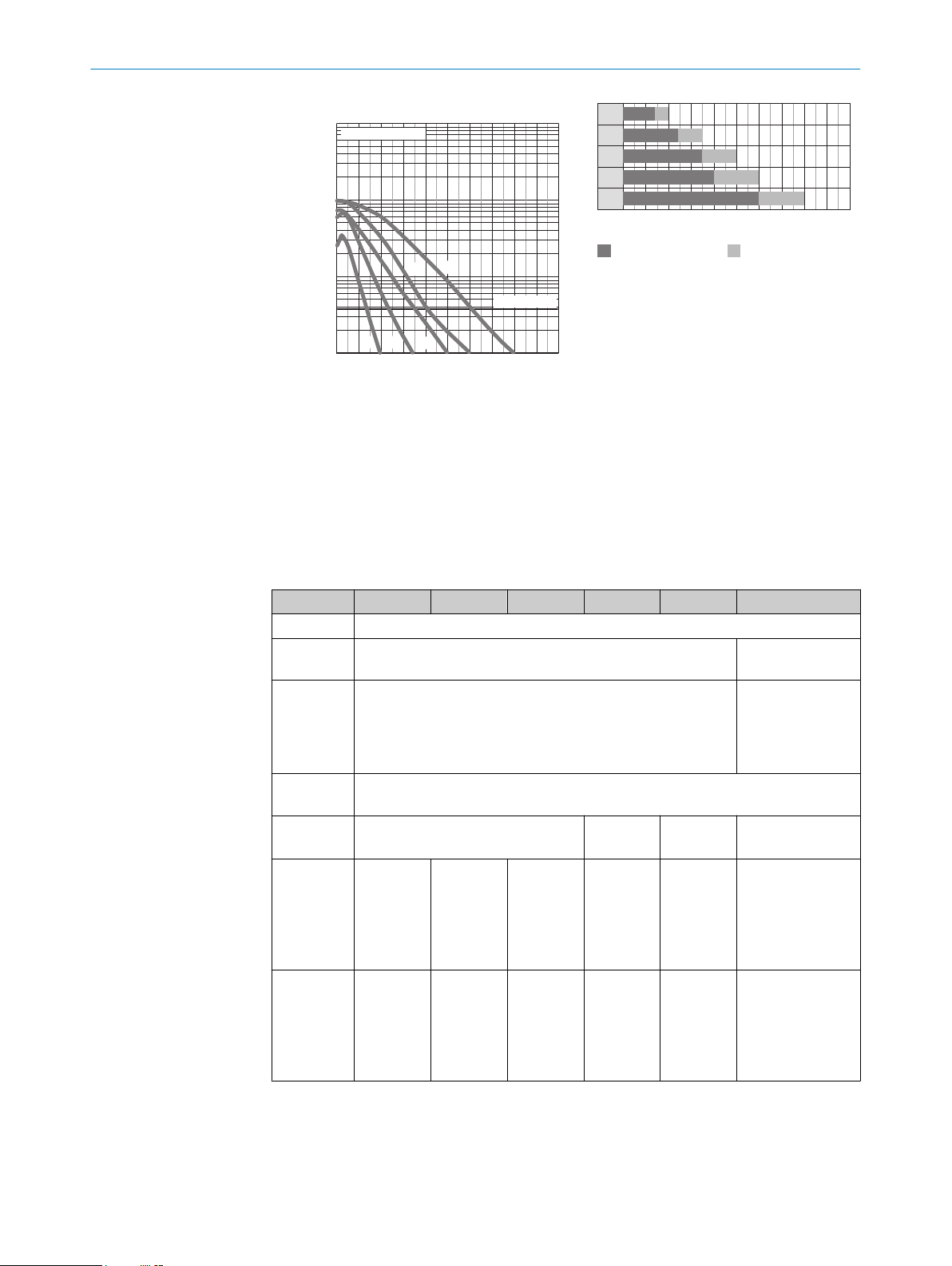
Figure 12: Bar graph 4: Chemical-resistant
reflector
Reflector PL10F CHEM
1
Reflector PL20 CHEM
2
Reflector P250 CHEM
3
Reflector P250H
Figure 11: Characteristic line 4: Chemical-
resistant reflector
Reflector PL10F CHEM
1
Reflector PL20 CHEM
2
Reflector P250 CHEM
3
Reflector P250H
4
Reflector PL40A Antifog
5
4
Reflector PL40A Antifog
5
9
Page 11
6 COMMISSIONING
Process data structure (Version 1.1)
A00 A70 A71 A72 A73 A75
IO-Link V1.1
Process
data
Bit 0 / Data
type
Bit 1 / Data
type
Bit... /
Descrip‐
tion / Data
type
Bit... /
Descrip‐
tion / Data
type
2 ...15 /
[empty]
QL2 / Boolean Qint.1 /
2 ...15 /
[time mea‐
surement
value] /
UInt 14
2 bytes 4 bytes
Byte 0: bits 15... 8
Byte 1: bits 7... 0
QL1 / Boolean
Boolean
2 … 15 /
[counter
value] /
UInt 14
2 … 15 /
[length /
measure‐
ment] /
speed
SInt14
QL2 /
Boolean
2 / Qint.
1 /
Boolean
3 … 15 /
[time mea‐
surement
value] /
UInt13
Byte 0: bits 31...
24
Byte 1: bits 13...
16
Byte 2: bits 15...
8
Byte 3: bits 7... 0
Qint.1 / Boolean
2 … 7 / [empty]
8 … 31 / [carrier
load] / UInt 24
7 Troubleshooting
The Troubleshooting table indicates measures to be taken if the sensor stops working.
en
LED indicator/fault pattern Cause Measures
Green LED flashes IO-Link communication None
Switching outputs do not
behave in accordance with
table 3 - table 4
Not all blue LEDs light up. a) Insufficient alignment
Yellow LED flashes Distance between sensor and
1. IO-Link communication
2. Change of the configuration
3. Short-circuit
b) Contamination of the
optical surfaces
c) Particles in the light
beam
d) Distance between sen‐
sor and reflector is too
large
e) Reflector is not suitable
reflector is too large / light
beam is not completely
aligned to the reflector /
1. None
2. Adjustment of the configura‐
tion
3. Check electrical connections
a) Check alignment
b) Cleaning of the optical
surfaces (sensor and
reflector).
c) Avoid contamination in
the air as far as possible
d) Check sensing range
e) SICK reflector is recom‐
mended
Check sensing range / check
alignment / SICK reflector is
recommended / Cleaning of
the optical surfaces (sensor
and reflector).
10
8022690.10DR | SICK
Subject to change without notice
Page 12
DISASSEMBLY AND DISPOSAL 8
LED indicator/fault pattern Cause Measures
reflector is not suitable / Front
screen and/or reflector is con‐
taminated.
The sensor is not displayed in
SOPASair
No connection can be made
to the sensor
1. Connection to another
hand-held exists.
2.The hand-held is outside of
the transmission range of the
sensor.
3. Bluetooth LE in the sensor
is deactivated.
4. Bluetooth LE in the handheld is deactivated.
5. MAC address filter acti‐
vated, hand-held not autho‐
rized.
1. The Android or iOS version
does not comply with require‐
ments.
2. SOPASair version does not
contain the required driver.
1. No connection or deactiva‐
tion of the existing connection.
2. Thorough check of installa‐
tion situation (e.g. shielding by
metal).
3. Activation of Bluetooth LE
via SiLink2 master or IO-Link
4. Activation of Bluetooth LE
5. No or change to MAC
address filter.
1. Check the operating system.
2. Uninstall SOPASair, install
the most current app version.
8 Disassembly and disposal
The sensor must be disposed of according to the applicable country-specific regula‐
tions. Efforts should be made during the disposal process to recycle the constituent
materials (particularly precious metals).
NOTE
Disposal of batteries, electric and electronic devices
According to international directives, batteries, accumulators and electrical or
•
electronic devices must not be disposed of in general waste.
The owner is obliged by law to return this devices at the end of their life to the
•
respective public collection points.
•
This symbol on the product, its package or in this document, indicates
that a product is subject to these regulations.
9 Maintenance
SICK sensors are maintenance-free.
We recommend doing the following regularly:
8022690.10DR | SICK
Subject to change without notice
Clean the external lens surfaces
•
Check the screw connections and plug-in connections
•
No modifications may be made to devices.
Subject to change without notice. Specified product properties and technical data are
not written guarantees.
11
Page 13
10 APPROVALS
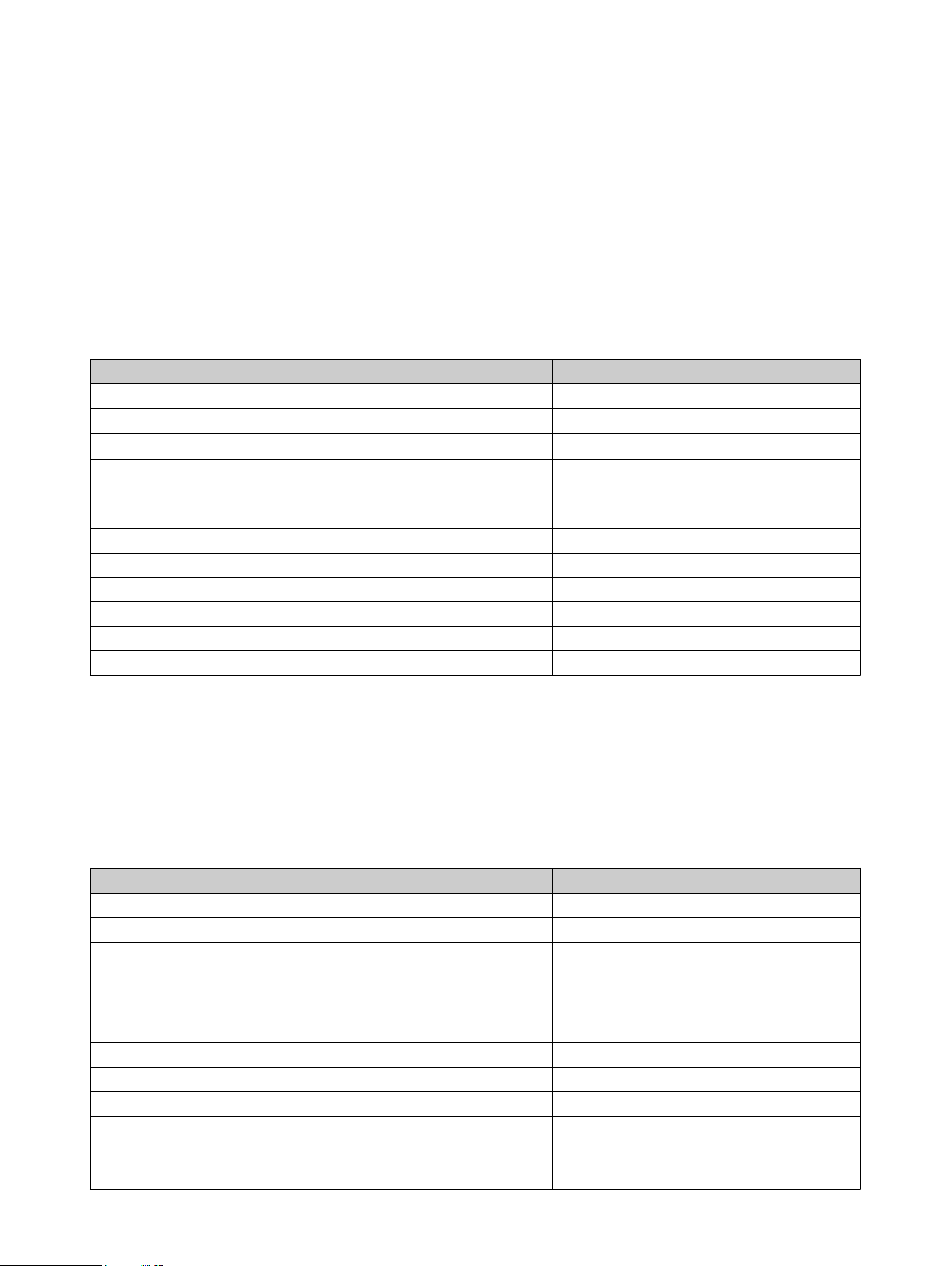
10 Approvals
10.1 Bluetooth® approvals
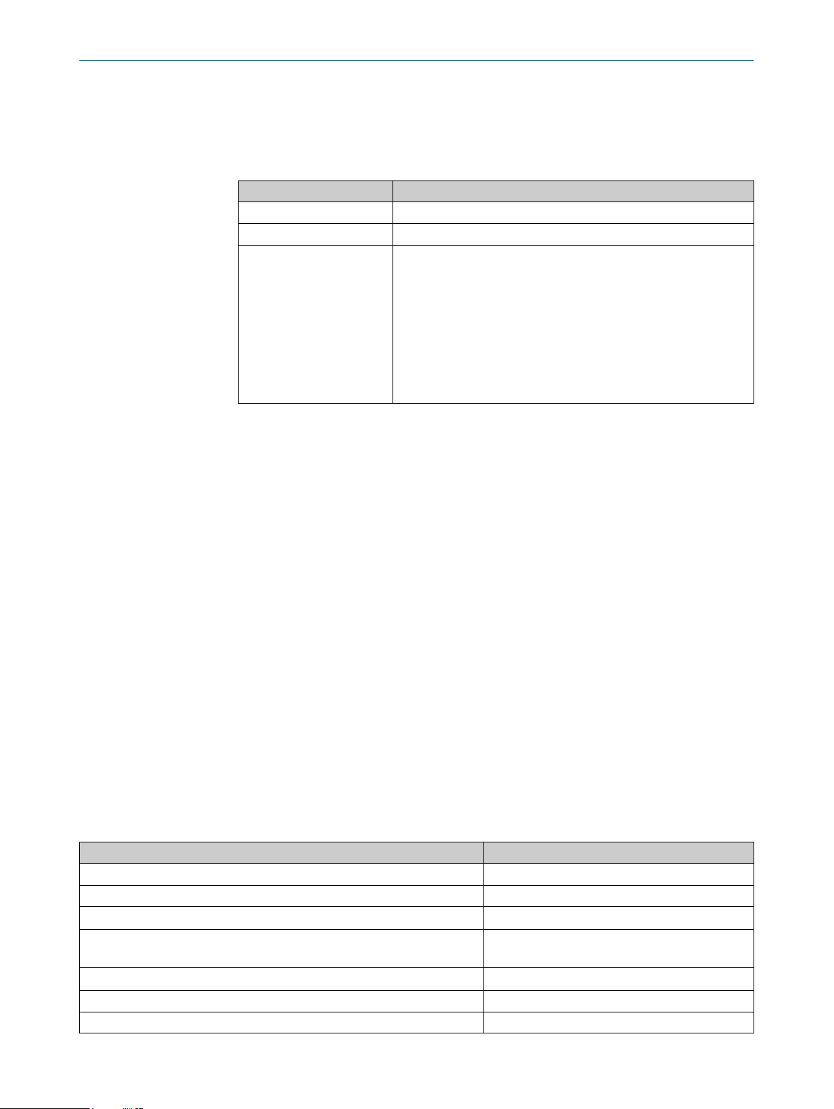
Country Comments
Canada IC: 21147-W16
USA FCC ID: 2AHDR-W16
Europe + EFTA EU countries
This device complies with Part 15 of the FCC Rules and with Industry Canada licenceexempt RSS standard(s). Operation is subject to the following two conditions: (1) this
device may not cause harmful interference, and (2) this device must accept any inter‐
ference received, including interference that may cause undesired operation.
Belgium (BE), Bulgaria (BG), Denmark (DK), Germany (DE), Estonia
(EE), Finland (FI), France (FR), Greece (GR), Ireland (IE), Italy (IT),
Latvia (LV), Lithuania (LT), Luxembourg (LU), Malta (MT), Nether‐
lands (NL), Austria (AT), Poland (PL), Portugal (PT), Romania (RO),
Sweden (SE), Slovakia (SK), Slovenia (SI), Spain (ES), Czech
Republic (CZ), Hungary (HU), United Kingdom (GB), Republic of
Cyprus (CY).
EFTA countries
Iceland, Liechtenstein, Norway, Switzerland
Le présent appareil est conforme aux CNR d'Industrie Canada applicables aux
appareils radio exempts de licence. L'exploitation est autorisée aux deux conditions
suivantes: (1) l'appareil ne doit pas produire de brouillage, et (2) l'utilisateur de
l'appareil doit accepter tout brouillage radioélectrique subi, même si le brouillage est
susceptible d'en compromettre le fonctionnement.
Changes or modifications made to this equipment not expressly approved by SICK AG
may void the FCC authorization to operate this equipment.
This equipment has been tested and found to comply with the limits for a Class A digital
device, pursuant to Part 15 of the FCC Rules. These limits are designed to provide rea‐
sonable protection against harmful interference when the equipment is operated in a
commercial environment. This equipment generates, uses, and can radiate radio fre‐
quency energy and, if not installed and used in accordance with the instruction manual,
may cause harmful interference to radio communications. Operation of this equipment
in a residential area is likely to cause harmful interference in which case the user will
be required to correct the interference at his own expense.
11 Technical data
11.1 Technical data
WLA16 Bluetooth
Sensing range (with reflector PL80A) 0 m ... 7 m
Light spot diameter/distance Ø 80 mm (5 m)
Supply voltage V
Current consumption ≤ 30 mA
Output current I
Max. response time ≤ 500 μs
Switching frequency 1,000 Hz
S
max.
DC 10 ... 30 V
1
< 50 mA
≤ 100 mA
2
3
4
12
8022690.10DR | SICK
Subject to change without notice
Page 14

WLA16 Bluetooth
Enclosure rating IP66, IP67, IP69K
Protection class III
Circuit protection A, B, C, D
5
Ambient operating temperature –40 °C ... +60 °C
1
16 VDC to 30 VDC, without load
2
10 VDC to 16 VDC, without load
3
Signal transit time with resistive load in switching mode. Deviating values possible in COM2 mode.
4
With a light/dark ratio of 1:1 in switching mode. Deviating values possible in IO-Link mode.
5
A = UV-connections reverse polarity protected
B = inputs and output reverse-polarity protected
C = Interference suppression
D = outputs overcurrent and short-circuit protected
11.2 Bluetooth technical data®
Features Values
Bluetooth® sensing range 100 m on sight
Radio type BLE
Radio class 2
Bluetooth® module manufacturer BROADCOM
Cypress Semiconductor Corporation
198 Champion Court San Jose
CA 95134-1709
RF band 2,402 - 2,480 MHz
Output power 2 dBM
Declaration ID D033906
Qualified design ID 89630
Specification name 4.1
Member company SICK AG
TECHNICAL DATA 11
8022690.10DR | SICK
Subject to change without notice
13
Page 15

WLA16 Bluetooth®
B E T R I E B S A N L E I T U N G
de
en
es
fr
it
ja
pt
ru
zh
Page 16

Beschriebenes Produkt
WLA16 - Bluetooth®
Hersteller
SICK AG
Erwin-Sick-Str. 1
79183 Waldkirch
Deutschland
Rechtliche Hinweise
Dieses Werk ist urheberrechtlich geschützt. Die dadurch begründeten Rechte bleiben
bei der Firma SICK AG. Die Vervielfältigung des Werks oder von Teilen dieses Werks ist
nur in den Grenzen der gesetzlichen Bestimmungen des Urheberrechtsgesetzes zuläs‐
sig. Jede Änderung, Kürzung oder Übersetzung des Werks ohne ausdrückliche schriftli‐
che Zustimmung der Firma SICK AG ist untersagt.
Die in diesem Dokument genannten Marken sind Eigentum ihrer jeweiligen Inhaber.
© SICK AG. Alle Rechte vorbehalten.
Originaldokument
Dieses Dokument ist ein Originaldokument der SICK AG.
8022690.10DR | SICK
Subject to change without notice
15
Page 17

INHALT
Inhalt
12 Zu Ihrer Sicherheit............................................................................. 17
12.1 Allgemeine Sicherheitshinweise.............................................................. 17
12.2 Hinweise zur UL Zulassung...................................................................... 17
13 Bestimmungsgemäße Verwendung............................................... 17
14 Bedien- und Anzeigeelemente........................................................ 17
15 Montage.............................................................................................. 18
16 Elektrische Installation..................................................................... 18
17 Inbetriebnahme................................................................................. 21
18 Störungsbehebung............................................................................ 23
18.1 ................................................................................................................... 24
19 Demontage und Entsorgung............................................................ 24
20 Wartung.............................................................................................. 25
21 Zulassungen....................................................................................... 25
21.1 Bluetooth® Zulassungen......................................................................... 25
22 Technische Daten.............................................................................. 26
22.1 Technische Daten..................................................................................... 26
22.2 Technische Daten Bluetooth®................................................................. 26
16
8022690.10DR | SICK
Subject to change without notice
Page 18
12 Zu Ihrer Sicherheit
2006/42/EC
NO
SAFETY
20
Ø 12,9
Ø 4,1
39,9
55,4
45,5
5
42
29,9
6
3
6,5
15
27,8
7,7
7,8
7,2
35,5
4,1
8,3
55,7
3
2
34,5
1
4
65
20
M12
18
Ø 4,1
39,9
55,4
55,7
45,5 5
7
42
29,9
52,9
6
17,5
3
6,5
15
28
7,5
35,5
4,1
3
2
34,5
1
4
65
12.1 Allgemeine Sicherheitshinweise
■
Lesen Sie vor der Inbetriebnahme des Geräts die Betriebsanleitung.
■
Der Anschluss, die Montage und die Konfiguration des Geräts dürfen nur
von geschultem Fachpersonal vorgenommen werden.
■
Bei diesem Gerät handelt es sich um kein sicherheitsgerichtetes Bauteil im
Sinne der EU-Maschinenrichtlinie.
■
Bei der Inbetriebnahme ist das Gerät ausreichend vor Feuchtigkeit und Ver‐
schmutzung zu schützen.
■
Die vorliegende Betriebsanleitung enthält Informationen, die während des Lebens‐
zyklus der Lichtschranke benötigt werden.
ZU IHRER SICHERHEIT 12
12.2 Hinweise zur UL Zulassung
The device must be supplied by a Class 2 source of supply.
UL Environmental Rating: Enclosure type 1
13 Bestimmungsgemäße Verwendung
Die WLA16 Bluetooth ist eine optoelektronische Reflexions-Lichtschranke (im Folgen‐
den Sensor genannt) und wird zum optischen, berührungslosen Erfassen von Sachen,
Tieren und Personen eingesetzt. Zur Funktion wird ein Reflektor benötigt. Bei jeder
anderen Verwendung und bei Veränderungen am Produkt verfällt jeglicher Gewährleis‐
tungsanspruch gegenüber der SICK AG.
14 Bedien- und Anzeigeelemente
8022690.10DR | SICK
Subject to change without notice
Abbildung 13: Maßzeichnung 1, Leitung
Mitte Optikachse
1
Abbildung 14: Maßzeichnung 2, Stecker
17
Page 19

15 MONTAGE
Befestigungsbohrung, Ø 4,1 mm
2
Anschluss
3
Anzeige-LED grün: Betriebsspan‐
4
nung aktiv
Anzeige-LED gelb: Status Lichtemp‐
5
fang
BluePilot blau: Ausrichthilfe
6
15 Montage
Sensor und Reflektor an geeignete Befestigungswinkel montieren (siehe SICK-ZubehörProgramm). Sensor und Reflektor zueinander ausrichten.
Maximal zulässiges Anzugsdrehmoment des Sensors von < 1,3 Nm beachten.
16 Elektrische Installation
Anschluss der Sensoren muss spannungsfrei (UV = 0 V) erfolgen. Je nach Anschlussart
sind die folgenden Informationen zu beachten:
– Steckeranschluss: Pinbelegung beachten
– Leitung: Adernfarbe
Erst nach Anschluss aller elektrischen Verbindungen die Spannungsversorgung (UV > 0
V) anlegen bzw. einschalten.
Erläuterungen zum Anschlussschema (Tabelle 5 - Tabelle 6)
Alarm = Alarmausgang (Tabelle 8)
Health = Alarmausgang (Tabelle 8)
MF (Pin-2-Konfiguration) = Externer Eingang, Teach-in, Schaltsignal
QL1/C = Schaltausgang, IO-Link Kommunikation
18
8022690.10DR | SICK
Subject to change without notice
Page 20
DC: 10 ... 30 V DC
1
2
4 3
1
2
4 3
1
2
4 3
1
2
4 3
1
2
4 3
1
2
4 3
1
2
4 3
Tabelle 5: DC
WLA16 -24162xxxA00
-34162xxxA00
1 + (L+)
2 MF
3 - (M)
4 QL1/C
Default: MF
Default:
Q Q
Q Q
QL1/C
-1x162xxxA00-24161xxxA0
1 = brn
2 = wht
3 = blu
4 = blk
ELEKTRISCHE INSTALLATION 16
-1x161xxxA00-2416xxxxA01-
0
-34161xxxA0
0
Q Q www.sick.com
Q Q
1 = brn
2 = wht
3 = blu
4 = blk
A99
-3416xxxxA01A99
8022709
www.sick.com
8022709
0.14 mm
AWG26
2
0.14 mm
2
AWG26
Tabelle 6: DC
WLA16 -24165
xxxA00
-34165
xxxA00
-1x165
xxxA00
-24163
xxxA00
-34163
xxxA00
-1x163x
xxA00
-24166x
xxA00
-34166x
xxA00
-1x166x
xxA00
-24164x
xxA00
-34164x
xxA00
-1x164x
xxA00
1 + (L+)
2 MF
3 - (M)
4 QL1/C
Default: MF Alarm Alarm Alarm Alarm Health Health Health Health
Default:
Q Q
Q Q
Q Q
Q Q
QL1/C
1 = brn
2 = wht
3 = blu
4 = blk
0.14
2
mm
AWG26
1 = brn
2 = wht
3 = blu
4 = blk
0.14
2
mm
AWG26
1 = brn
2 = wht
3 = blu
4 = blk
0.14
2
mm
AWG26
1 = brn
2 = wht
3 = blu
4 = blk
0.14
mm
AWG26
2
8022690.10DR | SICK
Subject to change without notice
19
Page 21
+ (L+)
Q
‒ (M)
+ (L+)
Q
‒ (M)
+ (L+)
Q
‒ (M)
+ (L+)
Q
‒ (M)
+ (L+)
Alarm
‒ (M)
+ (L+)
Health
‒ (M)
+ (L+)
Alarm
‒ (M)
+ (L+)
Health
‒ (M)
16 ELEKTRISCHE INSTALLATION
Tabelle 7: Push/Pull
Q
push-pull
(≤ 100 mA)
Q
push-pull
(≤ 100 mA)
Alarm
Alarmausgang: Der Sensor (WLA16 Bluetooth) verfügt über einen Vorausfallmeldeaus‐
gang ("Alarm" im Anschlussschema [siehe Tabelle 8]), der meldet, wenn der Sensor nur
noch eingeschränkt betriebsbereit ist. Dabei blinkt die Anzeige-LED. Mögliche Ursa‐
chen: Verschmutzung von Sensor oder Reflektor, Sensor ist dejustiert. Im Gutzustand:
LOW (0), bei zu starker Verschmutzung HIGH (1).
Health
Health-Ausgang: Der Sensor (WLA16 Bluetooth) verfügt über einen Vorausfallmeldeaus‐
gang ("Health" im Anschlussschema [siehe Tabelle 8), der meldet, wenn der Sensor nur
noch eingeschränkt betriebsbereit ist oder die Leitung unterbrochen ist. Mögliche Ursa‐
chen: Verschmutzung von Sensor oder Reflektor, Sensor ist dejustiert, Leitung ist
beschädigt. Im Gutzustand: HIGH (1), bei zu starker Verschmutzung oder Leitungsunter‐
brechung LOW (0). Dabei blinkt die gelbe Anzeige-LED.
Tabelle 8: Alarm / Health
Alarm (≤ 100 mA) Health (≤100 mA)
20
8022690.10DR | SICK
Subject to change without notice
Page 22
17 Inbetriebnahme
0
1.000
100
10
1
1 2 3 4 5 108 96 7
Funktionsreserve
Abstand in m
4
2
1
3
5
Schaltabstand
WLA16P-xxxxx1xx
Abstand in m
Schaltabstand
typ. max. Schaltabstand
1
2
3
4
5
0 1 4 5 6 72 8 9 103
3,5 50
6 80
3 4
0
6,5 9
0
7 10
0
7
10
0
7
Bluetooth® ist bei der Ersteinbetriebnahme eingeschaltet. SOPASair erhalten Sie im
Google PlayStore (Android) und im App Store (iOS).
Anforderungen an das Betriebssystem: Android-Version 6.0, iOS aktuellste Version.
1 Ausrichtung
Sensor auf geeigneten Reflektor ausrichten. Positionierung so wählen, dass der rote Sen‐
delichtstrahl in der Mitte des Reflektors auftrifft. Der Sensor muss freie Sicht auf den
Reflektor haben, es darf sich kein Objekt im Strahlengang befinden [siehe Abbildung 15].
Es ist darauf zu achten, dass die optischen Öffnungen von Sensor und Reflektor vollstän‐
dig frei sind.
INBETRIEBNAHME 17
8022690.10DR | SICK
Subject to change without notice
Abbildung 15: Ausrichtung 1 Abbildung 16: Ausrichtung 2
2 Schaltabstand
Distanz zwischen Sensor und Reflektor mit dem zugehörigen Diagramm [siehe
Abbildung 17] abgleichen (x = Schaltabstand, y = Funktionsreserve).
Abbildung 18: Balkendiagramm 1: Stan‐
dard Reflektor
Reflektor PL22
1
Reflektor P250, PL30A
2
Reflektor PL20A
3
Reflektor PL40A
Abbildung 17: Kennlinie 1: Standard
Reflektor
Reflektor PL22
1
Reflektor P250, PL30A
2
Reflektor PL20A
3
Reflektor PL40A
4
Reflektor PL80A, C110A
5
4
Reflektor PL80A, C110A
5
21
Page 23
0
1.000
100
10
1
1 2 3 4 5 108 96 7
Funktionsreserve
Abstand in m
3
2
1
Schaltabstand
WLA16P-xxxxx1xx
1
2
3
0
0
1 2
0
1,8 3
0
4,5 6
0
Schaltabstand typ. max. Schaltabstand
8
Abstand in m
2 6
10
4
7
1 5
9
3
0
1.000
100
10
1
1 2 3 4 5 108 96 7
Funktionsreserve
Abstand in m
4
3
1
2
Schaltabstand
WLA16P-xxxxx1xx
Schaltabstand typ. max. Schaltabstand
1
2
3
4
0
0 8
3 4
0
2,5 3
0
3,8 5
0
6 8
0
Abstand in m
2 6 104
7
1 5 93
17 INBETRIEBNAHME
Abbildung 19: Kennlinie 2: Reflexionsfolie
Reflexionsfolie REF-DG
1
Reflexionsfolie REF-IRF-56
2
Reflexionsfolie REF-AC1000
3
Abbildung 20: Balkendiagramm 2: Reflexi‐
onsfolie
Reflexionsfolie REF-DG (50 x
1
50 mm)
Reflexionsfolie REF-IRF-56 (50 x
2
50 mm)
Reflexionsfolie REF-AC1000 (50 x
3
50 mm)
Abbildung 21: Kennlinie 3: Feintrippel
Reflektoren
Reflektor PL10FH-1
1
Reflektor PL10F
2
Reflektor PL20F
3
Reflektor P250F
4
Abbildung 22: Balkendiagramm 3: Fein‐
trippel Reflektoren
Reflektor PL10FH-1
1
Reflektor PL10F
2
Reflektor PL20F
3
Reflektor P250F
4
22
8022690.10DR | SICK
Subject to change without notice
Page 24
0
1.000
100
10
1
1 2 3 4 5 108 96 7
Funktionsreserve
Abstand in m
5
4
3
21
Schaltabstand
WLA16P-xxxxx1xx
Abbildung 23: Kennlinie 4: chemikalienbe‐
Schaltabstand typ. max. Schaltabstand
1
2
3
4
5
0
0 8
1,4 2
0
2,4 3,5
0
3,5 5
0
4 6
0
6 8
0
Abstand in m
2 6 104
7
1 5 93
ständiger Reflektor
Reflektor PL10F CHEM
1
Reflektor PL20 CHEM
2
Reflektor P250 CHEM
3
Reflektor P250H
4
Reflektor PL40A Antifog
5
INBETRIEBNAHME 17
Abbildung 24: Balkendiagramm 4: chemi‐
kalienbeständiger Reflektor
Reflektor PL10F CHEM
1
Reflektor PL20 CHEM
2
Reflektor P250 CHEM
3
Reflektor P250H
4
Reflektor PL40A Antifog
5
Process data structure (Version 1.1)
A00 A70 A71 A72 A73 A75
IO-Link V1.1
Process
data
Bit 0/ Data
type
Bit 1/ Data
type
Bit... /
Descrip‐
tion / Data
type
Bit... /
Descrip‐
tion / Data
type
2...15 /
[empty]
QL2 / Boolean Qint.1 /
2...15 /
[Time
measure‐
ment
value] /
UInt 14
2 Byte 4 Byte
Byte 0 : Bit 15... 8
Byte 1: Bit 7... 0
QL1 / Boolean
Boolean
2 … 15 /
[Counter
2 … 15 /
[Length /
value] /
UInt 14
measure‐
ment] /
speed
SInt14
QL2 / Boo‐
lean
2 / Qint.
1 / Boo‐
lean
3 … 15 /
[Time
measure‐
ment
value] /
UInt13
Byte 0 : Bit 31...
24
Byte 1: Bit 13... 16
Byte 2: Bit 15... 8
Byte 3: Bit 7... 0
Qint.1 / Boolean
2…7 / [empty]
8 … 31 / [Carrier
load] / UInt 24
18 Störungsbehebung
8022690.10DR | SICK
Subject to change without notice
Tabelle Störungsbehebung zeigt, welche Maßnahmen durchzuführen sind, wenn die
Funktion des Sensors nicht mehr gegeben ist.
23
Page 25

18 STÖRUNGSBEHEBUNG
de
Anzeige-LED / Fehlerbild Ursache Maßnahme
grüne LED blinkt IO-Link Kommunikation keine
Schaltausgänge verhalten sich
nicht gemäß
Tabelle 7 - Tabelle 8
Nicht alle blauen LEDs leuch‐
ten.
gelbe LED blinkt Abstand zwischen Sensor und
In SOPASair wird der Sensor
nicht angezeigt
Es kann keine Verbindung
zum Sensor aufgebaut werden
1. IO-Link Kommunikation
2. Änderung der Konfiguration
3. Kurzschluss
a) ungenügende Ausrich‐
tung
b) Verschmutzung der opti‐
schen Flächen
c) Partikel im Lichtstrahl
d) Abstand zwischen Sen‐
sor und Reflektor ist zu
groß
e) Reflektor ist nicht geeig‐
net
Reflektor ist zu groß / Licht‐
strahl ist nicht vollständig auf
Reflektor ausgerichtet /
Reflektor ist nicht geeignet /
Frontscheibe und/oder Reflek‐
tor ist verschmutzt.
1. Verbindung zu einem ande‐
ren Handheld besteht.
2.Das Handheld befindet sich
außerhalb des Sendebereichs
des Sensors.
3. Bluetooth LE im Sensor ist
deaktiviert.
4. Bluetooth LE im Handheld
ist deaktiviert.
5. MAC-Adressfilter aktiviert,
Handheld nicht autorisiert.
1. Die Android bzw. iOS-Ver‐
sion entspricht nicht den
Anforderungen.
2. SOPASair Version enthält
nicht den erforderlichen Trei‐
ber.
1. keine
2. Anpassung der Konfigura‐
tion
3. Elektrische Anschlüsse prü‐
fen
a) Ausrichtung prüfen
b) Reinigung der optischen
Flächen (Sensor und
Reflektor).
c) sofern möglich, Ver‐
schmutzung in der Luft
vermeiden
d) Schaltabstand prüfen
e) Reflektor von SICK wird
empfohlen
Schaltabstand prüfen / Aus‐
richtung prüfen / Reflektor von
SICK wird empfohlen. / Reini‐
gung der optischen Flächen
(Sensor und Reflektor).
1. keine bzw. Deaktivierung der
bestehenden Verbindung.
2. Prüfung der Einbausituation
(z.B. Abschirmung durch
Metall).
3. Aktivierung von Bluetooth LE
per SiLink2 Master oder IOLink
4. Aktivierung von Bluetooth LE
5. keine bzw. Änderung des
MAC-Adress-Filters.
1. Prüfen Sie das Betriebssys‐
tem.
2. Deinstallieren Sie SOPASair,
Installieren Sie die aktuellste
App-Version.
19 Demontage und Entsorgung
Die Lichtschranke muss entsprechend den geltenden länderspezifischen Vorschriften
entsorgt werden. Bei der Entsorgung sollte eine werkstoffliche Verwertung (insbeson‐
dere der Edelmetalle) angestrebt werden.
24
8022690.10DR | SICK
Subject to change without notice
Page 26
20 Wartung
WARTUNG
HINWEIS
Entsorgung von Batterien, Elektro- und Elektronikgeräten
Gemäß den internationalen Vorschriften dürfen Batterien, Akkus sowie Elektro-
•
und Elektronikgeräte nicht mit dem Hausmüll entsorgt werden.
Der Besitzer ist gesetzlich verpflichtet, diese Geräte am Ende ihrer Lebensdauer
•
bei den entsprechenden öffentlichen Sammelstellen abzugeben.
•
Dieses Symbol auf dem Produkt, dessen Verpackung oder im vorliegen‐
den Dokument gibt an, dass ein Produkt den genannten Vorschriften unterliegt.
SICK-Sensoren sind wartungsfrei.
Wir empfehlen, in regelmäßigen Abständen
die optischen Grenzflächen zu reinigen
•
Verschraubungen und Steckverbindungen zu überprüfen
•
Veränderungen an Geräten dürfen nicht vorgenommen werden.
20
Irrtümer und Änderungen vorbehalten. Angegebene Produkteigenschaften und techni‐
sche Daten stellen keine Garantieerklärung dar.
21 Zulassungen
21.1 Bluetooth® Zulassungen
Land Kommentare
Canada IC: 21147-W16
USA FCC ID: 2AHDR-W16
Europa + EFTA EU Länder
This device complies with Part 15 of the FCC Rules and with Industry Canada licenceexempt RSS standard(s). Operation is subject to the following two conditions: (1) this
device may not cause harmful interference, and (2) this device must accept any interfe‐
rence received, including interference that may cause undesired operation.
Belgium (BE), Bulgaria (BG), Denm ark (DK), Germany (DE), Esto‐
nia (EE), Finland (FI), France (FR), Greece (GR), Ireland (IE), Italy
(IT), Latvia (LV), Lithuania (LT), Luxembourg (LU), Malta (MT),
Netherlands (NL), Austria (AT), Poland (PL), Portugal (PT), Romania
(RO), Sweden (SE), Slovakia (SK), Slovenia (SI), Spain (ES), Czech
Republic (CZ), Hungary (HU), Unit ed Kingdom (GB), Republic of
Cyprus (CY).
EFTA Länder
Iceland, Liechtenstein, Norway, Switzerland
8022690.10DR | SICK
Subject to change without notice
Le présent appareil est conforme aux CNR d'Industrie Canada applicables aux appa‐
reils radio exempts de licence. L'exploitation est autorisée aux deux conditions suivan‐
tes: (1) l'appareil ne doit pas produire de brouillage, et (2) l'utilisateur de l'appareil doit
accepter tout brouillage radioélectrique subi, même si le brouillage est susceptible d'en
compromettre le fonctionnement.
Changes or modifications made to this equipment not expressly approved by SICK AG
may void the FCC authorization to operate this equipment.
25
Page 27
22 TECHNISCHE DATEN
This equipment has been tested and found to comply with the limits for a Class A digital
device, pursuant to Part 15 of the FCC Rules. These limits are designed to provide rea‐
sonable protection against harmful interference when the equipment is operated in a
commercial environment. This equipment generates, uses, and can radiate radio fre‐
quency energy and, if not installed and used in accordance with the instruction manual,
may cause harmful interference to radio communications. Operation of this equipment
in a residential area is likely to cause harmful interference in which case the user will
be required to correct the interference at his own expense.
22 Technische Daten
22.1 Technische Daten
WLA16 Bluetooth
Schaltabstand (mit Reflektor PL80A) 0 m ... 7 m
Lichtfleckdurchmesser/Entfernung Ø 80 mm (5 m)
Versorgungsspannung U
V
Stromaufnahme ≤ 30 mA
Ausgangsstrom I
max.
Ansprechzeit max. ≤ 500 μs
Schaltfrequenz 1000 Hz
Schutzart IP66, IP67, IP69K
Schutzklasse III
Schutzschaltungen A, B, C, D
Betriebsumgebungstemperatur –40 °C ... +60 °C
1
16VDC...30VDC, ohne Last
2
10VDC...16VDC, ohne Last
3
Signallaufzeit bei ohmscher Last im Schaltmodus. Abweichende Werte im COM2-Modus möglich.
4
Bei Hell-Dunkel-Verhältnis 1:1 im Schaltmodus. Abweichende Werte im IO-Link-Modus möglich.
5
A = UV-Anschlüsse verpolsicher
B = Ein- und Ausgänge verpolsicher
C = Störimpulsunterdrückung
D = Ausgänge überstrom- und kurzschlussfest
DC 10 ... 30 V
1
< 50 mA
2
≤ 100 mA
3
4
5
22.2 Technische Daten Bluetooth®
Merkmale Werte
Bluetooth® Reichweite 100 m auf Sicht
Funkart BLE
Funkklasse 2
Hersteller Bluetooth® Modul BROADCOM
Cypress Semiconductor Corporation
198 Champion Court San Jose
CA 95134-1709
RF Band 2402 - 2480 MHz
Ausgangs-Leistung 2 dBM
Declaration ID D033906
Qualified Design ID 89630
Specification Name 4.1
Mitglieds Unternehmen SICK AG
26
8022690.10DR | SICK
Subject to change without notice
Page 28

WLA16 Bluetooth®
N O T I C E D ’ I N S T R U C T I O N
de
en
es
fr
it
ja
pt
ru
zh
Page 29

Produit décrit
WLA16 - Bluetooth®
Fabricant
SICK AG
Erwin-Sick-Straße 1
79183 Waldkirch
Allemagne
Remarques juridiques
Cet ouvrage est protégé par les droits d'auteur. Les droits établis restent dévolus à la
société SICK AG. La reproduction de l'ouvrage, même partielle, n'est autorisée que
dans le cadre légal prévu par la loi sur les droits d'auteur. Toute modification, tout
abrègement ou toute traduction de l'ouvrage est interdit sans l'accord écrit exprès de la
société SICK AG.
Les marques citées dans ce document sont la propriété de leurs détenteurs respectifs.
© SICK AG. Tous droits réservés.
Document original
Ce document est un document original de SICK AG.
28
8022690.10DR | SICK
Subject to change without notice
Page 30

Contenu
CONTENU
23 Pour votre sécurité............................................................................ 30
23.1 Consignes générales de sécurité............................................................. 30
23.2 Remarques sur l’homologation UL.......................................................... 30
24 Utilisation conforme.......................................................................... 30
25 Éléments de commande et d’affichage........................................ 30
26 Montage.............................................................................................. 31
27 Installation électrique....................................................................... 31
28 Mise en service.................................................................................. 34
29 Élimination des défauts................................................................... 37
29.1 ................................................................................................................... 37
30 Démontage et mise au rebut.......................................................... 37
31 Maintenance...................................................................................... 38
32 Homologations................................................................................... 38
32.1 Bluetooth® approvals............................................................................... 38
33 Caractéristiques techniques............................................................ 39
33.1 Caractéristiques techniques.................................................................... 39
33.2 Caractéristiques techniques Bluetooth®................................................ 39
8022690.10DR | SICK
Subject to change without notice
29
Page 31

2006/42/EC
NO
SAFETY
20
Ø 12,9
Ø 4,1
39,9
55,4
45,5
5
42
29,9
6
3
6,5
15
27,8
7,7
7,8
7,2
35,5
4,1
8,3
55,7
3
2
34,5
1
4
65
20
M12
18
Ø 4,1
39,9
55,4
55,7
45,5 5
7
42
29,9
52,9
6
17,5
3
6,5
15
28
7,5
35,5
4,1
3
2
34,5
1
4
65
23 POUR VOTRE SÉCURITÉ
23 Pour votre sécurité
23.1 Consignes générales de sécurité
■
Lire la notice d’instruction avant la mise en service.
■
Le raccordement, le montage et la configuration ne doivent être réalisés
que par un personnel qualifié.
■
N’est pas un composant de sécurité selon la Directive machines de l’UE.
■
Lors de la mise en service, protéger l’appareil contre l’humidité et la conta‐
mination.
■
Cette notice d’instruction contient des informations nécessaires durant le cycle de
vie du capteur.
23.2 Remarques sur l’homologation UL
The device must be supplied by a Class 2 source of supply.
UL Environmental Rating: Enclosure type 1
24 Utilisation conforme
WLA16 Bluetooth est une barrière réflexe optoélectronique (appelée capteur dans ce
document) qui permet la détection optique sans contact d’objets, d’animaux et de per‐
sonnes. Un réflecteur est nécessaire à son fonctionnement. Toute autre utilisation ou
modification du produit annule la garantie de SICK AG.
25 Éléments de commande et d’affichage
30
Illustration 25: Plan coté 1, câble
Centre de l’axe optique
1
Trou de fixation, Ø 4,1 mm
2
Raccordement
3
Illustration 26: Plan coté 2, connecteur
mâle
8022690.10DR | SICK
Subject to change without notice
Page 32

LED d’état verte : tension d’alimen‐
4
tation active
LED d’état jaune : état réception de
5
lumière
BluePilot bleu : outil d’alignement
6
26 Montage
Monter le capteur et le réflecteur sur un étrier adapté (voir la gamme d’accessoires
SICK). Aligner le capteur sur le réflecteur.
Respecter le couple de serrage maximum autorisé du capteur de < 1,3 Nm
27 Installation électrique
Le raccordement des capteurs doit s’effectuer hors tension (Uv = 0 V). Selon le mode
de raccordement, respecter les informations suivantes :
– Raccordement du connecteur : respecter l’affectation des broches
– Câble : couleur des fils
Après avoir terminé tous les raccordements électriques, appliquer ou activer l’alimenta‐
tion électrique (Uv > 0 V).
MONTAGE 26
Explications du schéma de raccordement (tableau 9- tableau 10 )
Alarme = sortie d’alarme (tableau 12)
Health = sortie d’alarme (tableau 12)
MF (configuration broche 2) = entrée externe, apprentissage, signal de commutation
QL1/C = sortie de commutation, communication IO-Link
8022690.10DR | SICK
Subject to change without notice
31
Page 33

1
2
4 3
1
2
4 3
1
2
4 3
1
2
4 3
1
2
4 3
1
2
4 3
1
2
4 3
27 INSTALLATION ÉLECTRIQUE
CC 10 ... 30 V CC
Tableau 9: CC
WLA16 -24162xxxA00
1 + (L+)
2 MF
3 - (M)
4 QL1/C
Par défaut :
MF
Par défaut :
QL1/C
-1x162xxxA00-24161xxxA0
-34162xxxA00
Q Q
Sortie Q Sortie Q
1 = brn (mar‐
3 = blu (bleu)
4 = blk (noir)
ron)
2 = wht
(blanc)
-1x161xxxA00-2416xxxxA01-
0
A99
-3416xxxxA01-
-34161xxxA0
A99
0
Sortie Q Sortie Q www.sick.com
8022709
Q Q
www.sick.com
8022709
1 = brn (mar‐
ron)
2 = wht
(blanc)
3 = blu (bleu)
4 = blk (noir)
0,14 mm
AWG26
2
0,14 mm
2
AWG26
Tableau 10: CC
WLA16 -24165
xxxA00
-34165
xxxA00
-1x165
xxxA00
-24163
xxxA00
-34163
xxxA00
-1x163x
xxA00
-24166x
xxA00
-34166x
xxA00
-1x166x
xxA00
-24164x
xxA00
-34164x
xxA00
-1x164x
xxA00
1 + (L+)
2 MF
3 - (M)
4 QL1/C
Par défaut :MFAlarme Alarme Alarme Alarme Health Health Health Health
Par défaut :
Sortie Q Sortie Q
Q Q
Sortie Q Sortie Q
Q Q
QL1/C
1 = brn
(mar‐
ron)
2 = wht
(blanc)
3 = blu
(bleu)
4 = blk
1 = brn
(marron)
2 = wht
(blanc)
3 = blu
(bleu)
4 = blk
(noir)
1 = brn
(marron)
2 = wht
(blanc)
3 = blu
(bleu)
4 = blk
(noir)
1 = brn
(marron)
2 = wht
(blanc)
3 = blu
(bleu)
4 = blk
(noir)
(noir)
0,14 m
2
m
0,14 m
2
m
AWG26
0,14 m
2
m
AWG26
0,14 m
AWG26
AWG26
2
m
32
8022690.10DR | SICK
Subject to change without notice
Page 34

Tableau 11: Push/Pull
+ (L+)
Q
‒ (M)
+ (L+)
Q
‒ (M)
+ (L+)
Q
‒ (M)
+ (L+)
Q
‒ (M)
+ (L+)
Alarm
‒ (M)
+ (L+)
Health
‒ (M)
+ (L+)
Alarm
‒ (M)
+ (L+)
Health
‒ (M)
Sortie Q
Push-pull
(≤ 100 mA)
Q
Push-pull
(≤ 100 mA)
INSTALLATION ÉLECTRIQUE 27
Alarme
Sortie alarme : le capteur (WLA16 Bluetooth) est équipé d’une sortie de signalisation
avant panne (« Alarme » dans le schéma de raccordement tableau 12) qui indique si le
fonctionnement du capteur est limité. La LED clignote. Causes possibles : encrasse‐
ment du capteur ou du réflecteur, capteur déréglé. Si l’état est correct : LOW (0), en cas
d’encrassement important HIGH (1).
Health
Sortie Health : le capteur (WLA16 Bluetooth) est équipé d’une sortie de signalisation
avant panne (« Health » dans le schéma de raccordement tableau 12) qui indique si le
fonctionnement du capteur est limité ou si le câble est coupé. Causes possibles :
encrassement du capteur ou du réflecteur, le capteur est déréglé, le câble est endom‐
magé. Si l’état est correct : HIGH (1), en cas d’encrassement important ou de coupure
de câble LOW (0). La LED jaune clignote.
Tableau 12: Alarme / Health
Alarme (≤ 100 mA) Health (≤100 mA)
8022690.10DR | SICK
Subject to change without notice
33
Page 35

0
1,000
100
10
1
2
(6.56)4(13.12)
10
(32.81)
8
(26.25)
6
(19.69)
Function reserve
Distance in m (feet)
4
2
1
3
5
Sensing range
WLA16P-xxxxx1xx
Sensing range Sensing range typ. max.
1
2
3
4
5
0
3.5 50
6 80
3 4
0
6.5 9
0
7 10
0
8
(26.25)
Distance in m (feet)
2
(6.56)
6
(19.69)
10
(32.81)
4
(13.12)
28 MISE EN SERVICE
28 Mise en service
Bluetooth® est activé lors de la première mise en service. SOPASair est disponible sur
Google PlayStore (Android) et l’App Store (iOS).
Système d’exploitation requis : version Android 6.0, dernière version iOS.
1 Alignement
Aligner le capteur sur un réflecteur adapté. Choisir la position de sorte que le faisceau
lumineux émis rouge touche le réflecteur en plein centre. Le capteur doit disposer d’un
champ de vision dégagé sur le réflecteur, il ne doit donc y avoir aucun objet dans la trajec‐
toire du faisceau [voir illustration 27]. S’assurer que les ouvertures optiques du capteur et
du réflecteur sont parfaitement dégagées.
34
Illustration 27: Alignement 1 Illustration 28: Alignement 2
2 Distance de commutation
Comparer la distance entre le capteur et le réflecteur avec le diagramme correspondant
[voir illustration 29] (x = distance de commutation, y = réserve de fonctionnement).
Illustration 30: Diagramme à barres 1 :
réflecteur standard
Réflecteur PL22
1
Réflecteurs P250, PL30A
2
Réflecteur PL20A
3
Réflecteur PL40A
Illustration 29: Caractéristique 1 : réflec‐
teur standard
Réflecteur PL22
1
Réflecteurs P250, PL30A
2
Réflecteur PL20A
3
Réflecteur PL40A
4
Réflecteurs PL80A, C110A
5
4
Réflecteurs PL80A, C110A
5
8022690.10DR | SICK
Subject to change without notice
Page 36

0
100
10
1
3
2
1
1,000
2
(6.56)4(13.12)
10
(32.81)
8
(26.25)
6
(19.69)
Function reserve
Distance in m (feet)
Sensing range
WLA16P-xxxxx1xx
Illustration 31: Caractéristique 2 : bande
1
2
3
0
0
1 2
0
1.8 3
0
4.5 6
0
Sensing range Sensing range typ. max.
8
(26.25)
Distance in m (feet)
2
(6.56)
6
(19.69)
10
(32.81)
4
(13.12)
1,000
100
10
1
4
3
1
2
0
2
(6.56)4(13.12)
10
(32.81)
8
(26.25)
6
(19.69)
Function reserve
Distance in m (feet)
Sensing range
WLA16P-xxxxx1xx
1
2
3
4
0
0
3 4
0
2.5 3
0
3.8 5
0
6 8
0
Sensing range Sensing range typ. max.
8
(26.25)
Distance in m (feet)
2
(6.56)
6
(19.69)
10
(32.81)
4
(13.12)
réflecteur
Bande réflecteur REF-DG
1
Bande réflecteur REF-IRF-56
2
Bande réflecteur REF-AC1000
3
MISE EN SERVICE 28
Illustration 32: Diagramme à barres 2 :
bande réflecteur
Bande réflecteur REF-DG (50 x
1
50 mm)
Bande réflecteur REF-IRF-56 (50 x
2
50 mm)
Bande réflecteur REF-AC1000 (50
3
x 50 mm)
8022690.10DR | SICK
Subject to change without notice
Illustration 34: Diagramme à barres 3 :
réflecteurs triple fin
Réflecteur PL10FH-1
1
Réflecteur PL10F
2
Réflecteur PL20F
3
Réflecteur P250F
4
Illustration 33: Caractéristique 3 : réflec‐
teurs triple fin
Réflecteur PL10FH-1
1
Réflecteur PL10F
2
Réflecteur PL20F
3
Réflecteur P250F
4
35
Page 37

0
1,000
100
10
1
2
(6.56)4(13.12)
10
(32.81)
8
(26.25)
6
(19.69)
Function reserve
Distance in m (feet)
5
4
3
21
Sensing range
WLA16P-xxxxx1xx
Sensing range Sensing range typ. max.
1
2
3
4
5
0
0 8
(26.25)
1.4 2
0
2.4 3.5
0
3.5 5
0
4 6
0
6 8
0
Distance in m (feet)
2
(6.56)
6
(19.69)
10
(32.81)
4
(13.12)
28 MISE EN SERVICE
Illustration 35: Caractéristique 4 : réflec‐
teur résistant aux produits chimiques
Réflecteur PL10F, CHEM
1
Réflecteur PL20, CHEM
2
Réflecteur P250, CHEM
3
Réflecteur P250H
4
Réflecteur PL40A antibuée
5
Illustration 36: Diagramme à barres 4 :
réflecteur résistant aux produits chi‐
miques
Réflecteur PL10F, CHEM
1
Réflecteur PL20, CHEM
2
Réflecteur P250, CHEM
3
Réflecteur P250H
4
Réflecteur PL40A antibuée
5
36
Structure des données de processus (version 1.1)
A00 A70 A71 A72 A73 A75
IO-Link V1.1
Données de
processus
Octet 0 : bit 15 ... 8
Octet 1 : bit 7 ... 0
Bit 0 / type
de données
Bit 1 / type
de données
Bit... / des‐
crip‐
tion / type
de données
Bit... / des‐
crip‐
tion / type
de données
15 / [vide]
QL2 / booléen Qint.1 /
2 ...
2 ...
15 / [vale
15 / [contr
ur de
mesure du
valeur] / U
temps] / U
lnt 14
2 octets 4 octets
Octet 0 : bit 31 ...
24
Octet 1 : bit 13 ...
16
Octet 2 : bit 15 ...
8
Octet 3 : bit 7 ... 0
QL1 / booléen
2 ...
e-
booléen
2 ...
15 / [lon‐
gueur / m
QL2 /
booléen
2 / Qint.
1 /
booléen
Qint.1 / booléen
2 ... 7 / [vide]
esure de
lnt 14
la
vitesse] /
Slnt14
3 ...
15 / [vale
8 ... 31 / [charge
support] / Ulnt 24
ur de
mesure du
temps] / U
lnt13
8022690.10DR | SICK
Subject to change without notice
Page 38

29 Élimination des défauts
Le tableau Élimination des défauts présente les mesures à appliquer si le capteur ne
fonctionne plus.
fr
LED d'état / image du défaut Cause Mesure
La LED verte clignote Communication IO-Link Aucune
Les sorties de commutation
ne se comportent pas selon
tableau 11 - tableau 12
Toutes les LED bleues ne cli‐
gnotent pas.
La LED jaune clignote La distance entre le capteur
Le capteur n’apparaît pas
dans SOPASair.
Impossible d’établir une
connexion avec le capteur
ÉLIMINATION DES DÉFAUTS 29
1. Communication IO-Link
2. Modification de la configu‐
ration
3. Court-circuit
a) alignement insuffisant
b) Encrassement des sur‐
faces optiques
c) Particules dans le fais‐
ceau lumineux
d) La distance entre le cap‐
teur et le réflecteur est
trop grande
e) Le réflecteur ne convient
pas
et le réflecteur est trop
grande / Le faisceau lumineux
n’est pas entièrement aligné
sur le réflecteur / Le réflec‐
teur ne convient pas / La vitre
frontale et/ou le réflecteur
sont encrassés.
1. Connexion existante avec
un autre appareil portatif.
2.L’appareil portatif se trouve
en dehors de la zone d’émis‐
sion du capteur.
3. Bluetooth LE désactivé
dans le capteur.
4. Bluetooth LE désactivé
dans l’appareil portatif.
5. Filtre d’adresse MAC activé,
appareil portatif non autorisé.
1. La version Android / iOS ne
satisfait pas aux exigences.
2. La version de SOPASair ne
renferme pas le pilote néces‐
saire.
1. Aucune
2. Adaptation de la configura‐
tion
3. Vérifier les raccordements
électriques
a) Vérifier l’alignement
b) Nettoyage des surfaces
optiques (capteur et
réflecteur).
c) Si possible, éviter
l’encrassement dans l’air
d) Vérifier la distance de
commutation
e) Réflecteur de SICK
recommandé
Vérifier la distance de commu‐
tation / Vérifier l’aligne‐
ment / Le réflecteur de SICK
est recommandé. / Nettoyage
des surfaces optiques (capteur
et réflecteur).
1. Aucune connexion ou
connexion existante désac‐
tivée.
2. Contrôle de la figure de
montage (p. ex. blindage par
du métal).
3. Activation de Bluetooth LE
par SiLink2 Master ou IO-Link
4. Activation de Bluetooth LE
5. aucun filtre d’adresse MAC
ou filtre d’adresse MAC
modifié.
1. Contrôlez le système
d’exploitation.
2. Désinstallez SOPASair et ins‐
tallez la dernière version de
l’appli.
30 Démontage et mise au rebut
Le capteur doit être mis au rebut selon les régulations spécifiques au pays respectif.
Dans la limite du possible, les matériaux du capteur doivent être recyclés (notamment
les métaux précieux).
8022690.10DR | SICK
Subject to change without notice
37
Page 39

MAINTENANCE
31
REMARQUE
Mise au rebut des batteries, des appareils électriques et électroniques
•
•
•
31 Maintenance
Les capteurs SICK ne nécessitent aucune maintenance.
Nous vous recommandons de procéder régulièrement
•
•
Ne procéder à aucune modification sur les appareils.
Selon les directives internationales, les batteries, accumulateurs et appareils élec‐
triques et électroniques ne doivent pas être mis au rebut avec les ordures
ménagères.
Le propriétaire est obligé par la loi de retourner ces appareils à la fin de leur cycle
de vie au point de collecte respectif.
Ce symbole sur le produit, son emballage ou dans ce document indique
qu’un produit est soumis à ces régulations.
au nettoyage des surfaces optiques
au contrôle des vissages et des connexions enfichables
Sujet à modification sans préavis. Les caractéristiques du produit et techniques four‐
nies ne sont pas une déclaration de garantie.
32 Homologations
32.1 Bluetooth® approvals
Country Comments
Canada IC: 21147-W16
USA FCC ID: 2AHDR-W16
Europe + EFTA EU countries
This device complies with Part 15 of the FCC Rules and with Industry Canada licenceexempt RSS standard(s). Operation is subject to the following two conditions: (1) this
device may not cause harmful interference, and (2) this device must accept any interfe‐
rence received, including interference that may cause undesired operation.
Belgium (BE), Bulgaria (BG), Denmark (DK), Germany (DE), Estonia
(EE), Finland (FI), France (FR), Greece (GR), Ireland (IE), Italy (IT),
Latvia (LV), Lithuania (LT), Luxembourg (LU), Malta (MT), Nether‐
lands (NL), Austria (AT), Poland (PL), Portugal (PT), Romania (RO),
Sweden (SE), Slovakia (SK), Slovenia (SI), Spain (ES), Czech Repu‐
blic (CZ), Hungary (HU), United Kingdom (GB), Republic of Cyprus
(CY).
EFTA countries
Iceland, Liechtenstein, Norway, Switzerland
38
Le présent appareil est conforme aux CNR d'Industrie Canada applicables aux appa‐
reils radio exempts de licence. L'exploitation est autorisée aux deux conditions sui‐
vantes: (1) l'appareil ne doit pas produire de brouillage, et (2) l'utilisateur de l'appareil
doit accepter tout brouillage radioélectrique subi, même si le brouillage est susceptible
d'en compromettre le fonctionnement.
Changes or modifications made to this equipment not expressly approved by SICK AG
may void the FCC authorization to operate this equipment.
8022690.10DR | SICK
Subject to change without notice
Page 40

CARACTÉRISTIQUES TECHNIQUES 33
This equipment has been tested and found to comply with the limits for a Class A digital
device, pursuant to Part 15 of the FCC Rules. These limits are designed to provide rea‐
sonable protection against harmful interference when the equipment is operated in a
commercial environment. This equipment generates, uses, and can radiate radio fre‐
quency energy and, if not installed and used in accordance with the instruction manual,
may cause harmful interference to radio communications. Operation of this equipment
in a residential area is likely to cause harmful interference in which case the user will
be required to correct the interference at his own expense.
33 Caractéristiques techniques
33.1 Caractéristiques techniques
WLA16 Bluetooth
Portée (avec réflecteur PL80A) 0 m ... 7 m
Diamètre spot / distance Ø 80 mm (5 m)
Tension d'alimentation U
V
Consommation électrique ≤ 30 mA
Courant de sortie I
max.
Temps de réponse max. ≤ 500 μs
Fréquence de commutation 1000 Hz
Indice de protection IP66, IP67, IP69K
Classe de protection III
Protections électriques A, B, C, D
Température de service –40 °C ... +60 °C
1
16 V CC ... 30 V CC, sans charge
2
10 V CC ... 16 V CC, sans charge
3
Durée du signal sur charge ohmique en mode commutation. Valeurs différentes possibles en mode COM2.
4
Pour un rapport clair/sombre de 1:1 en mode de commutation. Valeurs différentes possibles en mode IO-Link.
5
A = raccordements UV protégés contre les inversions de polarité
B = entrées et sorties protégées contre les inversions de polarité
C = Suppression des impulsions parasites
D = sorties protégées contre les courts-circuits et les surcharges
DC 10 ... 30 V
1
< 50 mA
2
≤ 100 mA
3
4
5
33.2 Caractéristiques techniques Bluetooth®
Caractéristiques Valeurs
Portée Bluetooth® 100 m à vue
Type de radio BLE
Classe de radio 2
Fabricant module Bluetooth® BROADCOM
Cypress Semiconductor Corporation
198 Champion Court San Jose
CA 95134-1709
Bande RF 2402 à 2480 MHz
Puissance de sortie 2 dBM
Declaration ID D033906
Qualified Design ID 89630
Nom spécification 4.1
Entreprise membre SICK AG
8022690.10DR | SICK
Subject to change without notice
39
Page 41

WLA16 Bluetooth®
M A N U A L D E I N S T R U Ç Õ E S
de
en
es
fr
it
ja
pt
ru
zh
Page 42

Produto descrito
WLA16 - Bluetooth®
Fabricante
SICK AG
Erwin-Sick-Str. 1
79183 Waldkirch
Alemanha
Notas legais
Reservados os direitos autorais do presente documento. Todos os direitos permane‐
cem em propriedade da empresa SICK AG. A reprodução total ou parcial desta obra só
é permitida dentro dos limites regulamentados pela Lei de Direitos Autorais. É proibido
alterar, resumir ou traduzir esta obra sem a autorização expressa e por escrito da SICK
AG.
As marcas citadas neste documento são de propriedade de seus respectivos pro‐
prietários.
© SICK AG. Todos os direitos reservados
Documento original
Este é um documento original da SICK AG.
8022690.10DR | SICK
Subject to change without notice
41
Page 43

ÍNDICE
Índice
34 Para a sua segurança....................................................................... 43
34.1 Instruções gerais de segurança.............................................................. 43
34.2 Indicações sobre a homologação UL...................................................... 43
35 Especificações de uso...................................................................... 43
36 Elementos de comando e indicação.............................................. 43
37 Montagem.......................................................................................... 44
38 Instalação elétrica............................................................................. 44
39 Colocação em operação.................................................................. 47
40 Eliminação de falhas........................................................................ 49
40.1 ................................................................................................................... 50
41 Desmontagem e descarte............................................................... 50
42 Manutenção....................................................................................... 51
43 Homologações................................................................................... 51
43.1 Bluetooth® approvals............................................................................... 51
44 Dados técnicos.................................................................................. 52
44.1 Dados técnicos......................................................................................... 52
44.2 Dados técnicos do Bluetooth®................................................................ 52
42
8022690.10DR | SICK
Subject to change without notice
Page 44

34 Para a sua segurança
2006/42/EC
NO
SAFETY
20
Ø 12,9
Ø 4,1
39,9
55,4
45,5
5
42
29,9
6
3
6,5
15
27,8
7,7
7,8
7,2
35,5
4,1
8,3
55,7
3
2
34,5
1
4
65
20
M12
18
Ø 4,1
39,9
55,4
55,7
45,5 5
7
42
29,9
52,9
6
17,5
3
6,5
15
28
7,5
35,5
4,1
3
2
34,5
1
4
65
34.1 Instruções gerais de segurança
■
Leia o manual de instruções antes de colocar em operação.
■
Conexão, montagem e configuração só podem ser realizadas por especia‐
listas treinados.
■
Não é um componente de segurança em conformidade com a Diretriz de
Máquinas da UE.
■
Ao colocar em operação, proteja o dispositivo de umidade e contaminação.
■
Esse manual de instruções contém informações necessárias durante o ciclo de
vida do sensor.
PARA A SUA SEGURANÇA 34
34.2 Indicações sobre a homologação UL
The device must be supplied by a Class 2 source of supply.
UL Environmental Rating: Enclosure type 1
35 Especificações de uso
O WLA16 Bluetooth é uma barreira de luz de reflexão optoeletrônica (doravante deno‐
minada “sensor”) utilizada para a detecção óptica, sem contato, de objetos, animais e
pessoas. É necessário um refletor para o funcionamento. Qualquer utilização diferente
ou alterações do produto ocasionam a perda da garantia da SICK AG.
36 Elementos de comando e indicação
8022690.10DR | SICK
Subject to change without notice
Figura 37: Desenho dimensional 1, cabo
Centro do eixo do sistema óptico
1
Furo de fixação, Ø 4,1 mm
2
Conexão
3
Figura 38: Desenho dimensional 2, conec‐
tor macho
43
Page 45

37 MONTAGEM
LED indicador verde: tensão de ali‐
4
mentação ativa
Indicador LED amarelo: status
5
recepção luminosa
BluePilot azul: auxílio de alinha‐
6
mento
37 Montagem
Montar o sensor e o refletor em cantoneiras de fixação adequadas (ver linha de
acessórios da SICK). Alinhar o sensor e o refletor entre si.
Observar o torque de aperto máximo permitido de < 1,3 Nm para o sensor.
38 Instalação elétrica
A conexão dos sensores deve ser realizada em estado desenergizado (UV = 0 V). Con‐
forme o tipo de conexão, devem ser observadas as seguintes informações:
– Conector: observar a disposição dos pinos
– Cabo: Cor dos fios
Instalar ou ligar a alimentação de tensão (UV > 0 V) somente após a conexão de todas
as conexões elétricas.
Explicações relativas ao esquema de conexões (tabela 13 -tabela 14 )
Alarme = saída de alarme (tabela 16)
Health = saída de alarme (tabela 16)
MF (configuração do pino 2) = entrada externa, Teach-in, sinal de comutação
QL1/C = saída de comutação, comunicação IO-Link
44
8022690.10DR | SICK
Subject to change without notice
Page 46

CC: 10 ... 30 V CC
1
2
4 3
1
2
4 3
1
2
4 3
1
2
4 3
1
2
4 3
1
2
4 3
1
2
4 3
Tabela 13: CC
WLA16 -24162xxxA00
-34162xxxA00
1 + (L+)
2 MF
3 - (M)
4 QL1/C
Default: MF
Default:
Q Q
Q Q
QL1/C
-1x162xxxA00-24161xxxA0
1 = brn (mar‐
rom)
2 = wht
(branco)
3 = blu (azul)
4 = blk
(preto)
INSTALAÇÃO ELÉTRICA 38
-1x161xxxA00-2416xxxxA01-
0
-3416xxxxA01-
-34161xxxA0
0
Q Q www.sick.com
Q Q
1 = brn (mar‐
rom)
2 = wht
(branco)
3 = blu (azul)
4 = blk
(preto)
-A99
-A99
8022709
www.sick.com
8022709
8022690.10DR | SICK
Subject to change without notice
0,14 mm
AWG26
2
0,14 mm
2
AWG26
Tabela 14: CC
WLA16 -24165
xxxA00
-34165
xxxA00
-1x165
xxxA00
-24163
xxxA00
-34163
xxxA00
-1x163x
xxA00
-24166x
xxA00
-34166x
xxA00
-1x166x
xxA00
-24164x
xxA00
-34164x
xxA00
-1x164x
xxA00
1 + (L+)
2 MF
3 - (M)
4 QL1/C
Default: MF Alarme Alarme Alarme Alarme Health Health Health Health
Default:
Q Q
Q Q
Q Q
Q Q
QL1/C
1 = brn
(mar‐
rom)
2 = wht
(branco
)
3 = blu
(azul)
4 = blk
1 = brn
(mar‐
rom)
2 = wht
(branco)
3 = blu
(azul)
4 = blk
(preto)
1 = brn
(mar‐
rom)
2 = wht
(branco)
3 = blu
(azul)
4 = blk
(preto)
1 = brn
(mar‐
rom)
2 = wht
(branco)
3 = blu
(azul)
4 = blk
(preto)
(preto)
0,14 m
2
m
0,14 m
2
m
AWG26
0,14 m
2
m
AWG26
0,14 m
AWG26
AWG26
2
m
45
Page 47

+ (L+)
Q
‒ (M)
+ (L+)
Q
‒ (M)
+ (L+)
Q
‒ (M)
+ (L+)
Q
‒ (M)
+ (L+)
Alarm
‒ (M)
+ (L+)
Health
‒ (M)
+ (L+)
Alarm
‒ (M)
+ (L+)
Health
‒ (M)
38 INSTALAÇÃO ELÉTRICA
Tabela 15: Push/Pull
push-pull
(≤ 100 mA)
push-pull
(≤ 100 mA)
Q
Q
Alarme
Saída de alarme: o sensor (WLA16 Bluetooth) dispõe de uma saída de pré-aviso de
falha (“Alarme” no esquema de conexões tabela 16), que avisa quando o sensor está
com operacionalidade restrita. O indicador LED está intermitente, neste caso. Causas
possíveis: contaminação do sensor ou do refletor, sensor desajustado. No estado OK:
LOW (0), em caso de forte contaminação HIGH (1).
Health
Saída Health: O sensor (WLA16 Bluetooth) dispõe de uma saída de aviso de pré-falha
(“Health” no esquema de conexões tabela 16), que avisa quando o sensor estiver com
operacionalidade restrita ou quando o cabo estiver interrompido. Causas possíveis:
sujeira do sensor ou do refletor, sensor está desajustado, cabo está danificado. No
estado OK: HIGH (1), em caso de forte ensujamento ou interrupção do cabo LOW (0). O
indicador LED amarelo está intermitente.
Tabela 16: Alarm / Health
Alarme (≤ 100 mA) Health (≤100 mA)
46
8022690.10DR | SICK
Subject to change without notice
Page 48

39 Colocação em operação
0
1,000
100
10
1
2
(6.56)4(13.12)
10
(32.81)
8
(26.25)
6
(19.69)
Function reserve
Distance in m (feet)
4
2
1
3
5
Sensing range
WLA16P-xxxxx1xx
Sensing range Sensing range typ. max.
1
2
3
4
5
0
3.5 50
6 80
3 4
0
6.5 9
0
7 10
0
8
(26.25)
Distance in m (feet)
2
(6.56)
6
(19.69)
10
(32.81)
4
(13.12)
O Bluetooth® é ligado na primeira colocação em operação. Você pode obter SOPASair
na Google PlayStore (Android) e na App Store (iOS).
Requisitos para o sistema operativo: Android-Version 6.0, iOS versão mais atual.
1 Alinhamento
Alinhar o sensor ao refletor adequado. Selecionar o posicionamento de forma que o feixe
da luz de emissão vermelho incida sobre o centro do refletor. O espaço entre o refletor e o
sensor deve estar livre; não pode haver nenhum objeto posicionado na trajetória do raio
luminoso [ver figura 39]. Certificar-se de que as aberturas ópticas do sensor e do refletor
estejam completamente livres.
COLOCAÇÃO EM OPERAÇÃO 39
8022690.10DR | SICK
Subject to change without notice
Figura 39: Alinhamento 1 Figura 40: Alinhamento 2
2 Distância de comutação
Equiparar a distância entre o sensor e o refletor com o respectivo diagrama [ver figura 41]
(x = distância de comutação, y = reserva de função).
Figura 42: Diagrama de barras 1: refletor
padrão
Refletor PL22
1
Refletor P250, PL30A
2
Refletor PL20A
3
Refletor PL40A
Figura 41: Curva característica 1: refletor
padrão
Refletor PL22
1
Refletor P250, PL30A
2
Refletor PL20A
3
Refletor PL40A
4
Refletor PL80A, C110A
5
4
Refletor PL80A, C110A
5
47
Page 49

0
100
10
1
3
2
1
1,000
2
(6.56)4(13.12)
10
(32.81)
8
(26.25)
6
(19.69)
Function reserve
Distance in m (feet)
Sensing range
WLA16P-xxxxx1xx
1
2
3
0
0
1 2
0
1.8 3
0
4.5 6
0
Sensing range Sensing range typ. max.
8
(26.25)
Distance in m (feet)
2
(6.56)
6
(19.69)
10
(32.81)
4
(13.12)
1,000
100
10
1
4
3
1
2
0
2
(6.56)4(13.12)
10
(32.81)
8
(26.25)
6
(19.69)
Function reserve
Distance in m (feet)
Sensing range
WLA16P-xxxxx1xx
1
2
3
4
0
0
3 4
0
2.5 3
0
3.8 5
0
6 8
0
Sensing range Sensing range typ. max.
8
(26.25)
Distance in m (feet)
2
(6.56)
6
(19.69)
10
(32.81)
4
(13.12)
39 COLOCAÇÃO EM OPERAÇÃO
Figura 43: Curva característica 2: fita
1
2
3
refletiva
Fita reflexiva REF-DG
Fita refletiva REF-IRF-56
Fita refletiva REF-AC1000
Figura 44: Diagrama de barras 2: fita
refletiva
Fita refletiva REF-DG (50 x 50 mm)
1
Fita refletiva REF-IRF-56 (50 x
2
50 mm)
Fita refletiva REF-AC1000 (50 x
3
50 mm)
48
Figura 46: Diagrama de barras 3: refleto‐
res com espelhos prismáticos finos
Refletor PL10FH-1
1
Refletor PL10F
2
Refletor PL20F
3
Refletor P250F
4
Figura 45: Curva característica 3: refleto‐
res com espelhos prismáticos finos
Refletor PL10FH-1
1
Refletor PL10F
2
Refletor PL20F
3
Refletor P250F
4
8022690.10DR | SICK
Subject to change without notice
Page 50

0
1,000
100
10
1
2
(6.56)4(13.12)
10
(32.81)
8
(26.25)
6
(19.69)
Function reserve
Distance in m (feet)
5
4
3
21
Sensing range
WLA16P-xxxxx1xx
Figura 47: Curva característica 4: refletor
Sensing range Sensing range typ. max.
1
2
3
4
5
0
0 8
(26.25)
1.4 2
0
2.4 3.5
0
3.5 5
0
4 6
0
6 8
0
Distance in m (feet)
2
(6.56)
6
(19.69)
10
(32.81)
4
(13.12)
resistente a químicos
Refletor PL10F CHEM
1
Refletor PL20 CHEM
2
Refletor P250 CHEM
3
Refletor P250H
4
Refletor PL40A Antifog
5
COLOCAÇÃO EM OPERAÇÃO 39
Figura 48: Diagrama de barras 4: refletor
resistente a químicos
Refletor PL10F CHEM
1
Refletor PL20 CHEM
2
Refletor P250 CHEM
3
Refletor P250H
4
Refletor PL40A Antifog
5
Process data structure (Version 1.1)
A00 A70 A71 A72 A73 A75
IO-Link V1.1
Process
data
Bit 0/ Data
type
Bit 1/ Data
type
Bit... / Des‐
cription /
Data type
Bit... / Des‐
cription /
Data type
2...15 /
[empty]
QL2 / Boolean Qint.1 /
2...15 /
[Time
measure‐
ment
value] /
UInt 14
2 Byte 4 Byte
Byte 0 : Bit 15... 8
Byte 1: Bit 7... 0
QL1 / Boolean
Boolean
2 … 15 /
[Counter
2 … 15 /
[Length /
value] /
UInt 14
measure‐
ment] /
speed
SInt14
QL2 / Boo‐
lean
2 / Qint.
1 / Boo‐
lean
3 … 15 /
[Time
measure‐
ment
value] /
UInt13
Byte 0 : Bit 31...
24
Byte 1: Bit 13... 16
Byte 2: Bit 15... 8
Byte 3: Bit 7... 0
Qint.1 / Boolean
2…7 / [empty]
8 … 31 / [Carrier
load] / UInt 24
40 Eliminação de falhas
8022690.10DR | SICK
Subject to change without notice
A tabela Eliminação de falhas mostra as medidas a serem executadas, quando o sen‐
sor não estiver funcionando.
49
Page 51

40 ELIMINAÇÃO DE FALHAS
pt
Indicador LED / padrão de
erro
LED verde intermitente Comunicação IO-Link Nenhuma
As saídas de comutação não
se comportam de acordo com
a
tabela 15 - tabela 16
Nem todos os LEDs azuis
acendem.
LED amarelo intermitente A distância entre sensor e
No SOPASair, o sensor não é
mostrado
Não é possível estabelecer
uma conexão com o sensor
Causa Medida
1. Comunicação IO-Link
2. Alteração da configuração
3. Curto-circuito
a) Alinhamento insuficiente
b) Sujeira nas áreas ópti‐
cas
c) Partícula no feixe de luz
d) Distância entre sensor e
refletor é grande demais
e) O refletor não é ade‐
quado
refletor é grande demais / O
feixe de luz não está total‐
mente alinhado para o refle‐
tor / O refletor não é ade‐
quado / O vidro frontal e/ou o
refletor está sujo.
1. Há uma conexão com um
outro dispositivo portátil.
2.O dispositivo portátil se
encontra fora da área de
transmissão do sensor.
3. Bluetooth LE no sensor
está desativado.
4. Bluetooth LE no dispositivo
portátil está desativado.
5. Filtro de endereço MAC ati‐
vado, dispositivo portátil não
autorizado.
1. A versão Android ou iOS
não corresponde aos requisi‐
tos.
2. A versão SOPASair não
contém o driver necessário.
1. Nenhuma
2. Adaptação da configuração
3. Verificar as conexões elétri‐
cas
a) Verificar o alinhamento
b) Limpeza das superfícies
c) se possível, evitar a
d) Verificar a distância de
e) É recomendado o refletor
Verificar a distância de
comutação / Verificar o alinha‐
mento / É recomendado o
refletor da SICK. / Limpeza das
superfícies ópticas (sensor e
refletor).
1. ausência ou desativação da
conexão existente.
2. Verificação da situação de
montagem (p.ex. blindagem
por metal).
3. Ativação do Bluetooth LE por
SiLink2 Master ou IO-Link
4. Ativação do Bluetooth LE
5. ausência ou modificação do
filtro MAC-Adress.
1. Verifique o sistema opera‐
tivo.
2. Desinstale Sie SOPASair, ins‐
tale a atual versão App.
ópticas (sensor e refle‐
tor).
sujeira no ar
comutação
da SICK
41 Desmontagem e descarte
O sensor deve ser descartado de acordo com os regulamentos específicos por país
aplicáveis. Deve-se realizar um esforço durante o processo de descarte para reciclar os
materiais constituintes (particularmente metais preciosos).
50
8022690.10DR | SICK
Subject to change without notice
Page 52

NOTA
Descarte de pilhas e dispositivos elétricos e eletrônicos
•
•
•
42 Manutenção
Os sensores SICK não requerem manutenção.
Recomendamos que se efetue em intervalos regulares
•
•
Não são permitidas modificações no aparelho.
MANUTENÇÃO
De acordo com diretrizes internacionais, pilhas, acumuladores e dispositivos
elétricos ou eletrônicos não devem ser descartados junto do lixo comum.
O proprietário é obrigado por lei a retornar esses dispositivos ao fim de sua vida
útil para os pontos de coleta públicos respectivos.
Este símbolo sobre o produto, seu pacote o neste documento, indica que
um produto está sujeito a esses regulamentos.
uma limpeza das superfícies ópticas
uma verificação das conexões roscadas e dos conectores
42
Sujeito a alterações sem aviso prévio. As propriedades do produto e os dados técnicos
especificados não constituem nenhum certificado de garantia.
43 Homologações
43.1 Bluetooth® approvals
Country Comments
Canada IC: 21147-W16
USA FCC ID: 2AHDR-W16
Europe + EFTA EU countries
This device complies with Part 15 of the FCC Rules and with Industry Canada licence-
-exempt RSS standard(s). Operation is subject to the following two conditions: (1) this
device may not cause harmful interference, and (2) this device must accept any interfe‐
rence received, including interference that may cause undesired operation.
Belgium (BE), Bulgaria (BG), Denmark (DK), Germany (DE), Estonia
(EE), Finland (FI), France (FR), Greece (GR), Ireland (IE), Italy (IT),
Latvia (LV), Lithuania (LT), Luxembourg (LU), Malta (MT), Nether‐
lands (NL), Austria (AT), Poland (PL), Portugal (PT), Romania (RO),
Sweden (SE), Slovakia (SK), Slovenia (SI), Spain (ES), Czech Repu‐
blic (CZ), Hungary (HU), United Kingdom (GB), Republic of Cyprus
(CY).
EFTA countries
Iceland, Liechtenstein, Norway, Switzerland
8022690.10DR | SICK
Subject to change without notice
Le présent appareil est conforme aux CNR d'Industrie Canada applicables aux appa‐
reils radio exempts de licence. L'exploitation est autorisée aux deux conditions suivan‐
tes: (1) l'appareil ne doit pas produire de brouillage, et (2) l'utilisateur de l'appareil doit
accepter tout brouillage radioélectrique subi, même si le brouillage est susceptible d'en
compromettre le fonctionnement.
Changes or modifications made to this equipment not expressly approved by SICK AG
may void the FCC authorization to operate this equipment.
51
Page 53

44 DADOS TÉCNICOS
This equipment has been tested and found to comply with the limits for a Class A digital
device, pursuant to Part 15 of the FCC Rules. These limits are designed to provide rea‐
sonable protection against harmful interference when the equipment is operated in a
commercial environment. This equipment generates, uses, and can radiate radio fre‐
quency energy and, if not installed and used in accordance with the instruction manual,
may cause harmful interference to radio communications. Operation of this equipment
in a residential area is likely to cause harmful interference in which case the user will
be required to correct the interference at his own expense.
44 Dados técnicos
44.1 Dados técnicos
WLA16 Bluetooth
Distância de comutação (com refletor PL80A) 0 m ... 7 m
Diâmetro do ponto de luz/distância Ø 80 mm (5 m)
Tensão de alimentação U
V
Consumo de corrente ≤ 30 mA
Corrente de saída I
max.
Tempo máx. de resposta ≤ 500 μs
Frequência de comutação 1000 Hz
Tipo de proteção IP66, IP67, IP69K
Classe de proteção III
Circuitos de proteção A, B, C, D
Temperatura ambiente de funcionamento –40 °C ... +60 °C
1
16VCC...30VCC, sem carga
2
10VCC...16VCC, sem carga
3
Tempo de duração do sinal em carga ôhmica no modo de comutação. Valores diferentes possíveis no modo COM2.
4
Na proporção claro-escuro 1:1 no modo de comutação. Valores diferentes possíveis no modo IO-Link.
5
A = UV-Anschlüsse verpolsicher
B = Ein- und Ausgänge verpolsicher
C = Störimpulsunterdrückung
D = Ausgänge überstrom- und kurzschlussfest
DC 10 ... 30 V
1
< 50 mA
2
≤ 100 mA
3
4
5
44.2 Dados técnicos do Bluetooth®
Características Valores
Bluetooth® alcance 100 m na vista
Tipo de transmissão BLE
Classe de transmissão 2
Fabricante módulo Bluetooth® BROADCOM
Cypress Semiconductor Corporation
198 Champion Court San Jose
CA 95134-1709
Banda RF 2402 - 2480 MHz
Potência de saída 2 dBM
Declaration ID D033906
Qualified Design ID 89630
Specification Name 4.1
Empresa associada SICK AG
52
8022690.10DR | SICK
Subject to change without notice
Page 54

WLA16 Bluetooth®
I S T R U Z I O N I P E R L ’ U S O
de
en
es
fr
it
ja
pt
ru
zh
Page 55

Descrizione prodotto
WLA16 - Bluetooth®
Produttore
SICK AG
Erwin-Sick-Str. 1
79183 Waldkirch
Germania
Note legali
Questo manuale è protetto dai diritti d'autore. I diritti che ne conseguono rimangono
alla ditta SICK. Il manuale o parti di esso possono essere fotocopiati esclusivamente
entro i limiti previsti dalle disposizioni di legge in materia di diritti d’autore. Non è con‐
sentito modificare, abbreviare o tradurre il presente manuale senza previa autorizza‐
zione scritta della ditta SICK AG.
I marchi riportati nel presente manuale sono di proprietà del rispettivo proprietario.
© SICK AG. Tutti i diritti riservati.
Documento originale
Questo documento è un originale della ditta SICK AG.
54
8022690.10DR | SICK
Subject to change without notice
Page 56

Indice
INDICE
45 Norme di sicurezza............................................................................ 56
45.1 Avvertenze di sicurezza generali.............................................................. 56
45.2 Indicazioni sull’omologazione UL............................................................. 56
46 Uso conforme alle disposizioni........................................................ 56
47 Elementi di comando e di visualizzazione..................................... 56
48 Montaggio.......................................................................................... 57
49 Installazione elettrica....................................................................... 57
50 Messa in servizio............................................................................... 59
51 Eliminazione difetti........................................................................... 62
51.1 ................................................................................................................... 62
52 Smontaggio e smaltimento............................................................. 63
53 Manutenzione.................................................................................... 63
54 Autorizzazioni..................................................................................... 64
54.1 Bluetooth® approvals............................................................................... 64
55 Dati tecnici.......................................................................................... 64
55.1 Dati tecnici................................................................................................ 64
55.2 Dati tecnici Bluetooth®............................................................................ 65
8022690.10DR | SICK
Subject to change without notice
55
Page 57

2006/42/EC
NO
SAFETY
20
Ø 12,9
Ø 4,1
39,9
55,4
45,5
5
42
29,9
6
3
6,5
15
27,8
7,7
7,8
7,2
35,5
4,1
8,3
55,7
3
2
34,5
1
4
65
20
M12
18
Ø 4,1
39,9
55,4
55,7
45,5 5
7
42
29,9
52,9
6
17,5
3
6,5
15
28
7,5
35,5
4,1
3
2
34,5
1
4
65
45 NORME DI SICUREZZA
45 Norme di sicurezza
45.1 Avvertenze di sicurezza generali
■
Prima di eseguire la messa in servizio, leggere le istruzioni per l’uso.
■
Il collegamento, il montaggio e la configurazione devono essere eseguiti
esclusivamente da personale tecnico qualificato.
■
Non è un componente di sicurezza ai sensi della Direttiva Macchine UE.
■
Durante la messa in servizio, proteggere il dispositivo dall’umidità e da pos‐
sibili contaminazioni.
■
Le presenti Istruzioni per l’uso contengono informazioni necessarie durante il ciclo
di vita del sensore.
45.2 Indicazioni sull’omologazione UL
The device must be supplied by a Class 2 source of supply.
UL Environmental Rating: Enclosure type 1
46 Uso conforme alle disposizioni
WLA16 Bluetooth è un sensore fotoelettrico a riflettore (di seguito detto sensore) utiliz‐
zato per il rilevamento ottico senza contatto di oggetti, animali e persone. Per il funzio‐
namento è necessario un riflettore. Se viene utilizzato diversamente e in caso di modifi‐
che del prodotto, decade qualsiasi diritto alla garanzia nei confronti di SICK.
47 Elementi di comando e di visualizzazione
56
Figura 49: Disegno quotato 1, cavo
Centro asse ottico
1
Foro di fissaggio, Ø 4,1 mm
2
Collegamento
3
Figura 50: Disegno quotato 2, connettore
maschio
8022690.10DR | SICK
Subject to change without notice
Page 58

Indicatore LED verde: tensione di
1
2
4 3
1
2
4 3
1
2
4 3
4
alimentazione attiva
Indicatore LED giallo: stato ricezione
5
luce
BluePilot blu: allineamento guidato
6
48 Montaggio
Montare il sensore e il riflettore su dei punti di fissaggio adatti (vedi il programma per
accessori SICK). Orientare reciprocamente il sensore e il rispettivo riflettore.
Rispettare il momento torcente massimo consentito del sensore di < 1,3Nm.
49 Installazione elettrica
Il collegamento dei sensori deve avvenire in assenza di tensione (UV = 0 V). In base al
tipo di collegamento si devono rispettare le seguenti informazioni:
– Collegamento a spina: osservare la configurazione dei pin
– Cavo: colore filo
Solamente in seguito alla conclusione di tutti i collegamenti elettrici, ripristinare o
accendere l’alimentazione elettrica (UV > 0 V).
MONTAGGIO 48
Spiegazioni dello schema di collegamento (tabella 17 - tabella 18)
Allarme = uscita allarme (tabella 20)
Health = uscita allarme (tabella 20
MF (configurazione pin 2) = ingresso esterno, teach-in, segnale di commutazione
QL1/C = uscita di commutazione, comunicazione IO-Link
DC: 10 ... 30 V DC
Tabella 17: DC
WLA16 -24162xxxA00
-34162xxxA00
1 + (L+)
2 MF
3 - (M)
4 QL1/C
Default: MF
Default:
QL1/C
Q Q
Q Q
-1x162x‐
xxA00
1 = brn
2 = wht
3 = blu
4 = blk
-24161x‐
xxA00
-34161x‐
xxA00
Q Q www.sick.com
Q Q
-1x161x‐
xxA00
1 = brn
2 = wht
3 = blu
4 = blk
-2416xxxxA01-
-3416xxxxA01-
8022709
www.sick.com
8022709
A99
A99
8022690.10DR | SICK
Subject to change without notice
0,14 mm
AWG26
2
0,14 mm
2
AWG26
57
Page 59

1
2
4 3
1
2
4 3
1
2
4 3
1
2
4 3
+ (L+)
Q
‒ (M)
+ (L+)
Q
‒ (M)
+ (L+)
Q
‒ (M)
+ (L+)
Q
‒ (M)
INSTALLAZIONE ELETTRICA
49
Tabella 18: DC
WLA16 -24165‐
xxxA00
-34165‐
xxxA00
-1x165‐
xxxA00
-24163‐
xxxA00
-34163‐
xxxA00
-1x163x‐
xxA00
-24166‐
xxxA00
-34166‐
xxxA00
-1x166x‐
xxA00
-24164‐
xxxA00
-34164‐
xxxA00
-1x164x‐
xxA00
1 + (L+)
2 MF
3 - (M)
4 QL1/C
Default: MF Allarme Allarme Allarme Allarme Health Health Health Health
Default:
Q Q
Q Q
Q Q
Q Q
QL1/C
1 = brn
2 = wht
3 = blu
4 = blk
1 = brn
2 = wht
3 = blu
4 = blk
1 = brn
2 = wht
3 = blu
4 = blk
1 = brn
2 = wht
3 = blu
4 = blk
Tabella 19: Push/Pull
Q
push-pull
(≤ 100 mA)
Q
push-pull
(≤ 100 mA)
0,14 m
2
m
AWG26
0,14 m
2
m
AWG26
0,14 m
2
m
AWG26
0,14 m
2
m
AWG26
Allarme
Uscita allarme: il sensore (WLA16 Bluetooth) dispone di un’uscita di comunicazione di
prevista avaria (“allarme” nello schema di collegamento tabella 20) che indica quando
il sensore è pronto per il funzionamento, ma ancora solo in modo limitato. In questo
caso l’indicatore LED lampeggia. Possibili cause: sensore o riflettore sporchi, il sensore
è disallineato. In buono stato: LOW (0), in caso di molto sporco HIGH (1).
58
Health
8022690.10DR | SICK
Subject to change without notice
Page 60

+ (L+)
Alarm
‒ (M)
+ (L+)
Health
‒ (M)
+ (L+)
Alarm
‒ (M)
+ (L+)
Health
‒ (M)
MESSA IN SERVIZIO 50
Uscita Health: il sensore (WLA16 Bluetooth) dispone di un’uscita di comunicazione di
prevista avaria (“Health” nello schema di collegamento tabella 20), che indica quando il
sensore è pronto per il funzionamento, ma ancora solo in modo limitato, o se la linea è
interrotta. Possibili cause: sensore o riflettore sporchi, sensore disallineato, linea dan‐
neggiata. In buono stato: HIGH (1), in caso di sporco elevato o interruzione della linea
LOW (0). In questo caso l’indicatore a LED giallo lampeggia.
Tabella 20: Allarme/Health
Allarme (≤ 100 mA) Health (≤ 100 mA)
50 Messa in servizio
Bluetooth® è acceso alla prima messa in servizio. SOPASair è disponibile in Google
PlayStore (Android) e in App Store (iOS).
Requisiti del sistema operativo: versione Android 6.0, versione iOS più recente.
1 Orientamento
Orientare il sensore sul relativo riflettore. Scegliere la posizione in modo tale che il raggio di
luce rosso emesso colpisca il centro del riflettore. Il sensore deve avere una visuale libera
sul riflettore, non ci deve essere nessun oggetto nella traiettoria del raggio [vedi figura 51].
Si deve fare attenzione affinché le aperture ottiche del sensore e del riflettore siano com‐
pletamente libere.
8022690.10DR | SICK
Subject to change without notice
Figura 51: Orientamento 1 Figura 52: Orientamento 2
2 Distanza di lavoro
Predisporre la distanza tra sensore e riflettore in base al diagramma corrispondente [vedi
figura 53] (x = distanza di lavoro, y = riserva operativa).
59
Page 61

0
1,000
100
10
1
2
(6.56)4(13.12)
10
(32.81)
8
(26.25)
6
(19.69)
Function reserve
Distance in m (feet)
4
2
1
3
5
Sensing range
WLA16P-xxxxx1xx
Sensing range Sensing range typ. max.
1
2
3
4
5
0
3.5 50
6 80
3 4
0
6.5 9
0
7 10
0
8
(26.25)
Distance in m (feet)
2
(6.56)
6
(19.69)
10
(32.81)
4
(13.12)
0
100
10
1
3
2
1
1,000
2
(6.56)4(13.12)
10
(32.81)
8
(26.25)
6
(19.69)
Function reserve
Distance in m (feet)
Sensing range
WLA16P-xxxxx1xx
1
2
3
0
0
1 2
0
1.8 3
0
4.5 6
0
Sensing range Sensing range typ. max.
8
(26.25)
Distance in m (feet)
2
(6.56)
6
(19.69)
10
(32.81)
4
(13.12)
50 MESSA IN SERVIZIO
Figura 53: Linea caratteristica 1: riflettore
standard
Riflettore PL22
1
Riflettore P250, PL30A
2
Riflettore PL20A
3
Riflettore PL40A
4
Riflettore PL80A, C110A
5
Figura 54: Diagramma a barre 1: riflettore
standard
Riflettore PL22
1
Riflettore P250, PL30A
2
Riflettore PL20A
3
Riflettore PL40A
4
Riflettore PL80A, C110A
5
60
Figura 56: Diagramma a barre 2: riflettore
adesivo
Riflettore adesivo REF-DG (50 x
1
50 mm)
Riflettore adesivo REF-IRF-56 (50 x
2
50 mm)
Riflettore adesivo REF-AC1000 (50
3
x 50 mm)
Figura 55: Linea caratteristica 2: riflettore
adesivo
Riflettore adesivo REF-DG
1
Riflettore adesivo REF-IRF-56
2
Riflettore adesivo REF-AC1000
3
8022690.10DR | SICK
Subject to change without notice
Page 62

1,000
100
10
1
4
3
1
2
0
2
(6.56)4(13.12)
10
(32.81)
8
(26.25)
6
(19.69)
Function reserve
Distance in m (feet)
Sensing range
WLA16P-xxxxx1xx
Figura 57: Linea caratteristica 3: riflettori
1
2
3
4
0
0
3 4
0
2.5 3
0
3.8 5
0
6 8
0
Sensing range Sensing range typ. max.
8
(26.25)
Distance in m (feet)
2
(6.56)
6
(19.69)
10
(32.81)
4
(13.12)
0
1,000
100
10
1
2
(6.56)4(13.12)
10
(32.81)
8
(26.25)
6
(19.69)
Function reserve
Distance in m (feet)
5
4
3
21
Sensing range
WLA16P-xxxxx1xx
Sensing range Sensing range typ. max.
1
2
3
4
5
0
0 8
(26.25)
1.4 2
0
2.4 3.5
0
3.5 5
0
4 6
0
6 8
0
Distance in m (feet)
2
(6.56)
6
(19.69)
10
(32.81)
4
(13.12)
a microprismi
Riflettore PL10FH-1
1
Riflettore PL10F
2
Riflettore PL20F
3
Riflettore P250F
4
MESSA IN SERVIZIO 50
Figura 58: Diagramma a barre 3: riflettori
a microprismi
Riflettore PL10FH-1
1
Riflettore PL10F
2
Riflettore PL20F
3
Riflettore P250F
4
8022690.10DR | SICK
Subject to change without notice
Figura 60: Diagramma a barre 4: riflettore
resistente alle sostanze chimiche
Riflettore PL10F CHEM
1
Riflettore PL20 CHEM
2
Riflettore P250 CHEM
3
Riflettore P250H
Figura 59: Linea caratteristica 4: riflettore
resistente alle sostanze chimiche
Riflettore PL10F CHEM
1
Riflettore PL20 CHEM
2
Riflettore P250 CHEM
3
Riflettore P250H
4
Riflettore PL40A Antifog
5
4
Riflettore PL40A Antifog
5
61
Page 63

50 MESSA IN SERVIZIO
Struttura dati di processo (versione 1.1)
IO-Link V1.1
Process
data
Bit 0/ Data
type
Bit 1/ Data
type
Bit... /
Descrip‐
tion / Data
type
Bit... /
Descrip‐
tion / Data
type
A00 A70 A71 A72 A73 A75
2 byte 4 byte
2...15 /
[empty]
Byte 0 : bit 15... 8
Byte 1: bit 7... 0
QL1 / Boolean
QL2 / Boolean Qint.1 /
Boolean
2...15 /
[Time
measure‐
ment
value] /
UInt 14
2 … 15 /
[Counter
value] /
UInt 14
2 … 15 /
[Length /
speed
measure‐
ment] /
SInt14
QL2 / Boo‐
lean
2 / Qint.
1 / Boo‐
lean
3 … 15 /
[Time
measure‐
ment
value] /
UInt13
Byte 0: bit 31... 24
Byte 1: bit 13... 16
Byte 2: bit 15... 8
Byte 3: bit 7... 0
Qint.1 / Boolean
8 … 31 / [Carrier
load] / UInt 24
2…7 / [empty]
51 Eliminazione difetti
La tabella di rimozione dei disturbi mostra quali provvedimenti si devono adottare
quando il sensore non funziona più.
it
Indicatore LED / figura di
errore
Il LED verde lampeggia Comunicazione IO-Link Nessuno
Le uscite di commutazione
non si comportano conforme‐
mente alle
tabella 19 - tabella 20
Non tutti i LED blu si accen‐
dono.
il LED giallo lampeggia La distanza tra sensore e
Causa Provvedimento
1. Comunicazione IO-Link
2. Modifica della configura‐
zione
3. Corto circuito
a) Allineamento insuffi‐
ciente
b) Impurità sulle superfici
ottiche
c) Particelle nel fascio
luminoso
d) La distanza tra sensore
e riflettore è troppo
grande
e) Riflettore non adatto
riflettore è troppo grande / il
raggio luminoso non è com‐
pletamente allineato al riflet‐
1. Nessuno
2. Adattamento della configu‐
razione
3. Controllare i collegamenti
elettrici
a) Controllare l’allineamento
b) Pulizia delle superfici otti‐
che (sensore e riflettore).
c) Evitare il più possibile
eventuali impurità
nell’aria
d) Controllare la distanza di
lavoro
e) Si raccomanda l’uso di
un riflettore SICK
Controllare la distanza di
lavoro / controllare l’allinea‐
mento / è consigliabile un
62
8022690.10DR | SICK
Subject to change without notice
Page 64

SMONTAGGIO E SMALTIMENTO 52
Indicatore LED / figura di
errore
In SOPASair il sensore non
viene visualizzato
Non può essere effettuato
alcun collegamento con il sen‐
sore
52 Smontaggio e smaltimento
Causa Provvedimento
tore / il riflettore non è ade‐
guato / Frontalino e/o riflet‐
tore sporchi.
1. Esiste un collegamento con
un altro handheld.
2.Handheld esterno al campo
di emissione del sensore.
3. Bluetooth LE disattivato nel
sensore.
4. Bluetooth LE disattivato
nell’handheld.
5. Filtro di indirizzo MAC atti‐
vato, handheld non autoriz‐
zato.
1. La versione Android o iOS
non corrisponde ai requisiti.
2. La versione SOPASair non
contiene il driver necessario.
riflettore di SICK. / Pulizia delle
superfici ottiche (sensore e
riflettore).
1. Nessun collegamento o
disattivazione del collegamento
esistente.
2. Verifica della condizione di
montaggio (ad es. schermo
mediante metallo).
3. Attivazione di Bluetooth LE
tramite master SiLink2 o IOLink
4. Attivazione di Bluetooth LE
5. Nessuna modifica del filtro
di indirizzo MAC.
1. Controllare il sistema opera‐
tivo.
2. Disinstallare SOPASair,
installare la versione App più
recente.
Il sensore deve essere smaltito in conformità con le leggi nazionali vigenti in materia.
Durante il processo di smaltimento, riciclare se possibile i materiali che compongono il
sensore (in particolare i metalli nobili).
INDICAZIONE
Smaltimento di batterie, dispositivi elettrici ed elettronici
•
•
•
53 Manutenzione
I sensori SICK sono esenti da manutenzione.
A intervalli regolari si consiglia di
•
•
Non è consentito effettuare modifiche agli apparecchi.
In base a direttive internazionali, le batterie, gli accumulatori e i dispositivi elettrici
ed elettronici non devono essere smaltiti tra i rifiuti generici.
Il titolare è tenuto per legge a riconsegnare questi dispositivi alla fine del loro ciclo
di vita presso i rispettivi punti di raccolta pubblici.
Questo simbolo presente sul prodotto, nella sua confezione o nel presente
documento, indica che un prodotto è soggetto a tali regolamentazioni.
pulire le superfici limite ottiche
Verificare i collegamenti a vite e gli innesti a spina
8022690.10DR | SICK
Subject to change without notice
Contenuti soggetti a modifiche senza preavviso. Le proprietà del prodotto e le schede
tecniche indicate non costituiscono una dichiarazione di garanzia.
63
Page 65

54 AUTORIZZAZIONI
54 Autorizzazioni
54.1 Bluetooth® approvals
Country Comments
Canada IC: 21147-W16
USA FCC ID: 2AHDR-W16
Europe + EFTA EU countries
This device complies with Part 15 of the FCC Rules and with Industry Canada licenceexempt RSS standard(s). Operation is subject to the following two conditions: (1) this
device may not cause harmful interference, and (2) this device must accept any interfe‐
rence received, including interference that may cause undesired operation.
Belgium (BE), Bulgaria (BG), Denmark (DK), Germany (DE), Estonia
(EE), Finland (FI), France (FR), Greece (GR), Ireland (IE), Italy (IT),
Latvia (LV), Lithuania (LT), Luxembourg (LU), Malta (MT), Nether‐
lands (NL), Austria (AT), Poland (PL), Portugal (PT), Romania (RO),
Sweden (SE), Slovakia (SK), Slovenia (SI), Spain (ES), Czech Repu‐
blic (CZ), Hungary (HU), United Kingdom (GB), Republic of Cyprus
(CY).
EFTA countries
Iceland, Liechtenstein, Norway, Switzerland
Le présent appareil est conforme aux CNR d'Industrie Canada applicables aux appa‐
reils radio exempts de licence. L'exploitation est autorisée aux deux conditions suivan‐
tes: (1) l'appareil ne doit pas produire de brouillage, et (2) l'utilisateur de l'appareil doit
accepter tout brouillage radioélectrique subi, même si le brouillage est susceptible d'en
compromettre le fonctionnement.
Changes or modifications made to this equipment not expressly approved by SICK AG
may void the FCC authorization to operate this equipment.
This equipment has been tested and found to comply with the limits for a Class A digital
device, pursuant to Part 15 of the FCC Rules. These limits are designed to provide rea‐
sonable protection against harmful interference when the equipment is operated in a
commercial environment. This equipment generates, uses, and can radiate radio fre‐
quency energy and, if not installed and used in accordance with the instruction manual,
may cause harmful interference to radio communications. Operation of this equipment
in a residential area is likely to cause harmful interference in which case the user will
be required to correct the interference at his own expense.
55 Dati tecnici
55.1 Dati tecnici
WLA16 Bluetooth
Distanza di commutazione (con riflettore PL80A) 0 m ... 7 m
Diametro punto luminoso/distanza Ø 80 mm (5 m)
Tensione di alimentazione U
Consumo di corrente ≤ 30 mA
Corrente di uscita I
Tempo di reazione max. ≤ 500 μs
Frequenza di commutazione 1000 Hz
max.
V
DC 10 ... 30 V
1
< 50 mA
≤ 100 mA
2
3
4
64
8022690.10DR | SICK
Subject to change without notice
Page 66

WLA16 Bluetooth
Tipo di protezione IP66, IP67, IP69K
Classe di protezione III
Commutazioni di protezione A, B, C, D
5
Temperatura ambientale di funzionamento –40 °C ... +60 °C
1
16 V DC ... 30 V DC, senza carico
2
10 V DC ... 16 V DC, senza carico
3
Durata segnale con carico ohmico in modalità di commutazione. Possibilità di valori diversi in modalità COM2.
4
Con rapporto chiaro/scuro 1:1 in modalità di commutazione. Possibilità di valori diversi in modalità IO-Link
5
A = UV-Allacciamenti protetti dall'inversione di polarità
B = entrate e uscite protette da polarità inversa
C = Soppressione impulsi di disturbo
D = uscite protette da sovracorrente e da cortocircuito.
55.2 Dati tecnici Bluetooth®
Caratteristiche Valori
Portata Bluetooth® 100 m a vista
Tipo di tecnologia radio BLE
Classe di potenza 2
Produttore modulo Bluetooth® BROADCOM
Cypress Semiconductor Corporation
198 Champion Court San Jose
CA 95134-1709
RF Band 2402-2480 MHz
Potenza in uscita 2 dBM
Declaration ID D033906
Qualified Design ID 89630
Specification Name 4.1
Membro associato SICK AG
DATI TECNICI 55
8022690.10DR | SICK
Subject to change without notice
65
Page 67

WLA16 Bluetooth®
I N S T R U C C I O N E S D E U S O
de
en
es
fr
it
ja
pt
ru
zh
Page 68

Producto descrito
WLA16 - Bluetooth®
Fabricante
SICK AG
Erwin-Sick-Str. 1
79183 Waldkirch
Alemania
Información legal
Este documento está protegido por la legislación sobre la propiedad intelectual. Los
derechos derivados de ello son propiedad de SICK AG. Únicamente se permite la repro‐
ducción total o parcial de este documento dentro de los límites establecidos por las
disposiciones legales sobre propiedad intelectual. Está prohibida la modificación, abre‐
viación o traducción del documento sin la autorización expresa y por escrito de SICK
AG.
Las marcas mencionadas en este documento pertenecen a sus respectivos propieta‐
rios.
© SICK AG. Reservados todos los derechos.
Documento original
Este es un documento original de SICK AG.
8022690.10DR | SICK
Subject to change without notice
67
Page 69

ÍNDICE
Índice
56 Para su seguridad............................................................................. 69
56.1 Indicaciones generales de seguridad..................................................... 69
56.2 Indicaciones sobre la homologación UL................................................. 69
57 Uso conforme a lo previsto.............................................................. 69
58 Elementos de mando y visualización............................................. 69
59 Montaje............................................................................................... 70
60 Instalación eléctrica.......................................................................... 70
61 Puesta en servicio............................................................................. 73
62 Resolución de problemas................................................................ 76
62.1 ................................................................................................................... 76
63 Desmontaje y eliminación............................................................... 77
64 Mantenimiento.................................................................................. 77
65 Homologaciones................................................................................ 77
65.1 Bluetooth® approvals............................................................................... 77
66 Datos técnicos................................................................................... 78
66.1 Datos técnicos.......................................................................................... 78
66.2 Datos técnicos de Bluetooth®................................................................. 78
68
8022690.10DR | SICK
Subject to change without notice
Page 70

56 Para su seguridad
2006/42/EC
NO
SAFETY
20
Ø 12,9
Ø 4,1
39,9
55,4
45,5
5
42
29,9
6
3
6,5
15
27,8
7,7
7,8
7,2
35,5
4,1
8,3
55,7
3
2
34,5
1
4
65
20
M12
18
Ø 4,1
39,9
55,4
55,7
45,5 5
7
42
29,9
52,9
6
17,5
3
6,5
15
28
7,5
35,5
4,1
3
2
34,5
1
4
65
56.1 Indicaciones generales de seguridad
■
Lea las instrucciones de uso antes de realizar la puesta en servicio.
■
Únicamente personal especializado y debidamente cualificado debe llevar
a cabo las tareas de conexión, montaje y configuración.
■
No se trata de un componente de seguridad según las definiciones de la
directiva de máquinas de la UE.
■
Al realizar la puesta en servicio, el dispositivo se debe proteger ante la
humedad y la contaminación.
■
Las presentes instrucciones de uso contienen la información necesaria para toda
la vida útil del sensor.
PARA SU SEGURIDAD 56
56.2 Indicaciones sobre la homologación UL
The device must be supplied by a Class 2 source of supply.
UL Environmental Rating: Enclosure type 1
57 Uso conforme a lo previsto
La WLA16 Bluetooth es una fotocélula optoelectrónica de reflexión sobre espejo (en lo
sucesivo llamada sensor) empleada para la detección óptica y sin contacto de objetos,
animales y personas. Para que funcione es necesario un reflector. Cualquier uso dife‐
rente al previsto o modificación en el producto invalidará la garantía por parte de SICK
AG.
58 Elementos de mando y visualización
8022690.10DR | SICK
Subject to change without notice
Figura 61: Dibujo acotado 1, cable
Centro del eje óptico
1
Figura 62: Dibujo acotado 2, conector
69
Page 71

59 MONTAJE
Orificio de fijación, Ø 4,1 mm
2
Conexión
3
LED indicador verde: tensión de ali‐
4
mentación activa
LED indicador amarillo: estado de
5
recepción de luz
BluePilot azul: ayuda de alineación
6
59 Montaje
Montar el sensor y el reflector en escuadras de fijación adecuadas (véase el programa
de accesorios SICK). Alinear el sensor y el reflector entre sí.
Respetar el par de apriete máximo admisible del sensor de < 1,3 Nm.
60 Instalación eléctrica
Los sensores deben conectarse sin tensión (Uv = 0 V). Debe tenerse en cuenta la
siguiente información en función del tipo de conexión:
– Conexión de enchufes: observar la asignación de terminales
– Cable: color del hilo
No aplicar ni conectar la alimentación de tensión (UV > 0 V) hasta que no se hayan fina‐
lizado todas las conexiones eléctricas.
Explicaciones relativas al diagrama de conexiones (tabla 21 - véase tabla 22)
Alarm = salida de alarma (tabla 24)
Health = salida de alarma (tabla 24)
MF (configuración 2 de terminales) = entrada externa, teach-in, señal de conmutación
QL1/C = salida conmutada, comunicación con sistema IO-Link
70
8022690.10DR | SICK
Subject to change without notice
Page 72

CC: 10 ... 30 V CC
1
2
4 3
1
2
4 3
1
2
4 3
1
2
4 3
1
2
4 3
1
2
4 3
1
2
4 3
Tabla 21: CC
WLA16 -24162xxxA00
-34162xxxA00
1 + (L+)
2 MF
3 - (M)
4 QL1/C
Por defecto:
Q Q
MF
Por defecto:
Q Q
QL1/C
-1x162xxxA00-24161xxxA0
1 = brn
(marrón)
2 = wht
(blanco)
3 = blu (azul)
4 = blk
(negro)
INSTALACIÓN ELÉCTRICA 60
-1x161xxxA00-2416xxxxA01-
0
-3416xxxxA01-
-34161xxxA0
0
Q Q www.sick.com
Q Q
1 = brn
(marrón)
2 = wht
(blanco)
3 = blu (azul)
4 = blk
(negro)
A99
A99
8022709
www.sick.com
8022709
8022690.10DR | SICK
Subject to change without notice
0,14 mm
AWG26
2
0,14 mm
2
AWG26
Tabla 22: CC
WLA16 -24165
xxxA00
-34165
xxxA00
-1x165
xxxA00
-24163
xxxA00
-34163
xxxA00
-1x163x
xxA00
-24166x
xxA00
-34166x
xxA00
-1x166x
xxA00
-24164x
xxA00
-34164x
xxA00
-1x164x
xxA00
1 + (L+)
2 MF
3 - (M)
4 QL1/C
Por defecto:MFAlarm Alarm Alarm Alarm Health Health Health Health
Por defecto:
Q Q
Q Q
Q Q
Q Q
QL1/C
1 = brn
(marrón
)
2 = wht
(blanco)
3 = blu
(azul)
4 = blk
1 = brn
(marrón)
2 = wht
(blanco)
3 = blu
(azul)
4 = blk
(negro)
1 = brn
(marrón)
2 = wht
(blanco)
3 = blu
(azul)
4 = blk
(negro)
1 = brn
(marrón)
2 = wht
(blanco)
3 = blu
(azul)
4 = blk
(negro)
(negro)
0,14 m
2
m
0,14 m
2
m
AWG26
0,14 m
2
m
AWG26
0,14 m
m
AWG26
AWG26
2
71
Page 73

+ (L+)
Q
‒ (M)
+ (L+)
Q
‒ (M)
+ (L+)
Q
‒ (M)
+ (L+)
Q
‒ (M)
+ (L+)
Alarm
‒ (M)
+ (L+)
Health
‒ (M)
+ (L+)
Alarm
‒ (M)
+ (L+)
Health
‒ (M)
60 INSTALACIÓN ELÉCTRICA
Tabla 23: Push/Pull
push-pull
(≤ 100 mA)
push-pull
(≤ 100 mA)
Q
Q
Alarm
Salida Alarm: el sensor (WLA16 Bluetooth) dispone de una salida para preavisos de
fallo (“Alarm” en el diagrama de conexiones tabla 24), que indica cuándo puede usarse
el sensor ya solo con limitaciones. En este caso el LED indicador parpadeará. Causas
posibles: el sensor o el reflector están sucios, o el sensor está desajustado. Si está en
buen estado: LOW (0), si está muy sucio: HIGH (1).
Health
Salida Health: el sensor (WLA16 Bluetooth) dispone de una salida para preavisos de
fallo (“Health” en el diagrama de conexiones tabla 24), que indica cuándo puede
usarse el sensor ya solo con limitaciones o cuándo se ha interrumpido el cable. Causas
posibles: el sensor o el reflector están sucios, el sensor está desajustado, o el cable
está dañado. En buen estado: HIGH (1), si está muy sucio, o si la línea está interrum‐
pida: LOW (0). En este caso el LED indicador amarillo parpadeará.
Tabla 24: Alarm / Health
Alarm (≤ 100 mA) Health (≤100 mA)
72
8022690.10DR | SICK
Subject to change without notice
Page 74

61 Puesta en servicio
0
1,000
100
10
1
2
(6.56)4(13.12)
10
(32.81)
8
(26.25)
6
(19.69)
Function reserve
Distance in m (feet)
4
2
1
3
5
Sensing range
WLA16P-xxxxx1xx
Sensing range Sensing range typ. max.
1
2
3
4
5
0
3.5 50
6 80
3 4
0
6.5 9
0
7 10
0
8
(26.25)
Distance in m (feet)
2
(6.56)
6
(19.69)
10
(32.81)
4
(13.12)
Bluetooth® se conecta durante la puesta en servicio inicial. SOPASair está disponible
en Google PlayStore (Android) y en App Store (iOS).
Requisitos del sistema operativo: versión 6.0 de Android; última versión de iOS.
1 Alineación
Oriente el sensor hacia un reflector adecuado. Seleccione una posición que permita que el
haz de luz roja del emisor incida en el centro del reflector. El sensor debe tener una visión
despejada del reflector, no puede haber ningún objeto en la trayectoria del haz [véase
figura 63]. Hay que procurar que las aperturas ópticas del sensor y del reflector estén com‐
pletamente libres.
PUESTA EN SERVICIO 61
8022690.10DR | SICK
Subject to change without notice
Figura 63: Alineación 1 Figura 64: Alineación 2
2 Distancia de conmutación
Comparar la distancia entre el sensor y el reflector con el diagrama correspondiente
[véase figura 65] (x = distancia de conmutación, y = reserva de funcionamiento).
Figura 66: Gráfico de barras 1: reflector
estándar
Reflector PL22
1
Reflector P250, PL30A
2
Reflector PL20A
3
Reflector PL40A
Figura 65: Curva característica 1: reflector
estándar
Reflector PL22
1
Reflector P250, PL30A
2
Reflector PL20A
3
Reflector PL40A
4
Reflector PL80A, C110A
5
4
Reflector PL80A, C110A
5
73
Page 75

0
100
10
1
3
2
1
1,000
2
(6.56)4(13.12)
10
(32.81)
8
(26.25)
6
(19.69)
Function reserve
Distance in m (feet)
Sensing range
WLA16P-xxxxx1xx
1
2
3
0
0
1 2
0
1.8 3
0
4.5 6
0
Sensing range Sensing range typ. max.
8
(26.25)
Distance in m (feet)
2
(6.56)
6
(19.69)
10
(32.81)
4
(13.12)
1,000
100
10
1
4
3
1
2
0
2
(6.56)4(13.12)
10
(32.81)
8
(26.25)
6
(19.69)
Function reserve
Distance in m (feet)
Sensing range
WLA16P-xxxxx1xx
1
2
3
4
0
0
3 4
0
2.5 3
0
3.8 5
0
6 8
0
Sensing range Sensing range typ. max.
8
(26.25)
Distance in m (feet)
2
(6.56)
6
(19.69)
10
(32.81)
4
(13.12)
61 PUESTA EN SERVICIO
Figura 67: Curva característica 2: lámina
de reflexión
Lámina de reflexión REF-DG
1
Lámina de reflexión REF-IRF-56
2
Lámina de reflexión REF-AC1000
3
Figura 68: Gráfico de barras 2: lámina de
reflexión
Lámina de reflexión REF-DG (50 x
1
50 mm)
Lámina de reflexión REF-IRF-56
2
(50 x 50 mm)
Lámina de reflexión REF-AC1000
3
(50 x 50 mm)
74
Figura 70: Gráfico de barras 3: reflectores
microcelda
Reflector PL10FH-1
1
Reflector PL10F
2
Reflector PL20F
3
Reflector P250F
4
Figura 69: Curva característica 3: reflecto‐
res microcelda
Reflector PL10FH-1
1
Reflector PL10F
2
Reflector PL20F
3
Reflector P250F
4
8022690.10DR | SICK
Subject to change without notice
Page 76

0
1,000
100
10
1
2
(6.56)4(13.12)
10
(32.81)
8
(26.25)
6
(19.69)
Function reserve
Distance in m (feet)
5
4
3
21
Sensing range
WLA16P-xxxxx1xx
Figura 71: Curva característica 4: reflector
Sensing range Sensing range typ. max.
1
2
3
4
5
0
0 8
(26.25)
1.4 2
0
2.4 3.5
0
3.5 5
0
4 6
0
6 8
0
Distance in m (feet)
2
(6.56)
6
(19.69)
10
(32.81)
4
(13.12)
resistente a los productos químicos
Reflector PL10F CHEM
1
Reflector PL20 CHEM
2
Reflector P250 CHEM
3
Reflector P250H
4
Reflector PL40A Antifog
5
PUESTA EN SERVICIO 61
Figura 72: Gráfico de barras 4: reflector
resistente a los productos químicos
Reflector PL10F CHEM
1
Reflector PL20 CHEM
2
Reflector P250 CHEM
3
Reflector P250H
4
Reflector PL40A Antifog
5
Estructura de datos de proceso (versión 1.1)
A00 A70 A71 A72 A73 A75
IO-Link V1.1
Datos de
proceso
Bit 0 / tipo
de datos
Bit 1 / tipo
de datos
Bit... / des‐
cripción /
tipo de
datos
Bit... / des‐
cripción /
tipo de
datos
2 ... 15 /
[vacío]
QL2 / booleano Qint.1 /
2 ... 15 /
[valor de
medición
de
tiempo] /
UInt 14
2 bytes 4 bytes
Byte 0: bit 15 ... 8
Byte 1: bit 7 ... 0
QL1 / booleano
booleano
2 … 15 /
[valor de
conta‐
dor] / UInt
2 … 15 /
[longitud /
medición
de veloci‐
14
dad] /
SInt14
QL2 / boo‐
leano
2 / Qint.
1 / boo‐
leano
3 … 15 /
[valor de
medición
de
tiempo] /
UInt13
Byte 0: bit 31 ...
24
Byte 1: bit 13 ...
16
Byte 2: bit 15 ... 8
Byte 3: bit 7 ... 0
Qint.1 / booleano
2 … 7 / [vacío]
8 … 31 / [carga de
portador] / UInt
24
8022690.10DR | SICK
Subject to change without notice
75
Page 77

62 RESOLUCIÓN DE PROBLEMAS
62 Resolución de problemas
La tabla “Resolución de problemas” muestra las medidas que hay que tomar cuando
ya no está indicado el funcionamiento del sensor.
es
LED indicador / imagen de
error
El LED verde parpadea Comunicación con sistema IO-
Las salidas conmutadas no se
comportan según la
tabla 23 - tabla 24
No se iluminan todos los LED
azules.
El LED amarillo parpadea La distancia entre el sensor y
En SOPASair no se muestra el
sensor
No se puede establecer
conexión con el sensor
Causa Acción
Link
1. Comunicación con sistema
IO-Link
2. Cambio de la configuración
3. Cortocircuito
a) Alineación insuficiente
b) Suciedad en las superfi‐
cies ópticas
c) Partículas en el haz de
luz
d) La distancia entre el
sensor y el reflector es
excesiva
e) El reflector no es ade‐
cuado
el reflector es demasiado
grande / El haz luminoso no
está completamente alineado
con el reflector / El reflector
no es adecuado / La pantalla
frontal y/o el reflector están
sucios.
1. Existe conexión con otro
dispositivo portátil.
2.El dispositivo portátil está
fuera de la zona de emisión
del sensor.
3. Bluetooth LE está desacti‐
vado en el sensor.
4. Bluetooth LE está desacti‐
vado en el dispositivo portátil.
5. El filtro de dirección MAC
está activado; el dispositivo
portátil no está autorizado.
1. La versión de Android o iOS
no cumple con los requisitos.
2. La versión de SOPASair no
contiene el controlador reque‐
rido.
ninguna
1. ninguna
2. Adaptación de la configu‐
ración
3. Comprobar las conexiones
eléctricas
a) Comprobar la alineación
b) Limpieza de las superfi‐
cies ópticas (sensor y
reflector).
c) Siempre que sea posible,
evitar la suciedad en el
aire
d) Comprobar la distancia
de conmutación
e) Se recomienda usar un
reflector SICK
Comprobar la distancia de con‐
mutación / Comprobar la ali‐
neación / Se recomienda usar
un reflector SICK. / Limpieza
de las superficies ópticas (sen‐
sor y reflector).
1. Ninguna o desactivar la
conexión existente.
2. Comprobar la situación de
montaje (p. ej., apantalla‐
miento metálico).
3. Activar Bluetooth LE
mediante el maestro SiLink2 o
IO-Link
4. Activar Bluetooth LE
5. Ninguna o cambiar el filtro
de dirección MAC.
1. Compruebe el sistema ope‐
rativo.
2. Desinstale SOPASair; instale
la última versión de la apli‐
cación.
76
8022690.10DR | SICK
Subject to change without notice
Page 78

63 Desmontaje y eliminación
El sensor debe eliminarse de conformidad con las reglamentaciones nacionales aplica‐
bles. Como parte del proceso de eliminación, se debe intentar reciclar los materiales al
máximo posible (especialmente los metales preciosos).
INDICACIÓN
Eliminación de las baterías y los dispositivos eléctricos y electrónicos
De acuerdo con las directivas internacionales, las pilas, las baterías y los dispositi‐
•
vos eléctricos y electrónicos no se deben eliminar junto con la basura doméstica.
La legislación obliga a que estos dispositivos se entreguen en los puntos de reco‐
•
gida públicos al final de su vida útil.
•
La presencia de este símbolo en el producto, el material de embalaje o
este documento indica que el producto está sujeto a esta reglamentación.
DESMONTAJE Y ELIMINACIÓN 63
64 Mantenimiento
Los sensores SICK no precisan mantenimiento.
A intervalos regulares, recomendamos:
Limpiar las superficies ópticas externas
•
Comprobar las uniones roscadas y las conexiones.
•
No se permite realizar modificaciones en los aparatos.
Sujeto a cambio sin previo aviso. Las propiedades y los datos técnicos del producto no
suponen ninguna declaración de garantía.
65 Homologaciones
65.1 Bluetooth® approvals
Country Comments
Canada IC: 21147-W16
USA FCC ID: 2AHDR-W16
Europe + EFTA EU countries
Belgium (BE), Bulgaria (BG), Denmark (DK), Germany (DE), Estonia
(EE), Finland (FI), France (FR), Greece (GR), Ireland (IE), Italy (IT),
Latvia (LV), Lithuania (LT), Luxembourg (LU), Malta (MT), Nether‐
lands (NL), Austria (AT), Poland (PL), Portugal (PT), Romania (RO),
Sweden (SE), Slovakia (SK), Slovenia (SI), Spain (ES), Czech Repu‐
blic (CZ), Hungary (HU), United Kingdom (GB), Republic of Cyprus
(CY).
EFTA countries
Iceland, Liechtenstein, Norway, Switzerland
8022690.10DR | SICK
Subject to change without notice
This device complies with Part 15 of the FCC Rules and with Industry Canada licenceexempt RSS standard(s). Operation is subject to the following two conditions: (1) this
device may not cause harmful interference, and (2) this device must accept any interfe‐
rence received, including interference that may cause undesired operation.
77
Page 79

66 DATOS TÉCNICOS
Le présent appareil est conforme aux CNR d'Industrie Canada applicables aux appa‐
reils radio exempts de licence. L'exploitation est autorisée aux deux conditions suivan‐
tes: (1) l'appareil ne doit pas produire de brouillage, et (2) l'utilisateur de l'appareil doit
accepter tout brouillage radioélectrique subi, même si le brouillage est susceptible d'en
compromettre le fonctionnement.
Changes or modifications made to this equipment not expressly approved by SICK AG
may void the FCC authorization to operate this equipment.
This equipment has been tested and found to comply with the limits for a Class A digital
device, pursuant to Part 15 of the FCC Rules. These limits are designed to provide
reasonable protection against harmful interference when the equipment is operated in
a commercial environment. This equipment generates, uses, and can radiate radio fre‐
quency energy and, if not installed and used in accordance with the instruction manual,
may cause harmful interference to radio communications. Operation of this equipment
in a residential area is likely to cause harmful interference in which case the user will
be required to correct the interference at his own expense.
66 Datos técnicos
66.1 Datos técnicos
WLA16 Bluetooth
Distancia de conmutación (con reflector PL80A) 0 m ... 7 m
Diámetro del punto luminoso/distancia Ø 80 mm (5 m)
Tensión de alimentación U
V
Consumo de corriente ≤ 30 mA
Intensidad de salida I
max.
Tiempo de respuesta máx. ≤ 500 μs
Frecuencia de conmutación 1.000 Hz
DC 10 ... 30 V
1
< 50 mA
2
≤ 100 mA
3
4
Tipo de protección IP66, IP67, IP69K
Clase de protección III
Circuitos de protección A, B, C, D
5
Temperatura ambiente de servicio –40 °C ... +60 °C
1
16 VCC...30 VCC, sin carga
2
10 VCC...16 VCC, sin carga
3
Duración de la señal con carga óhmica en modo de conmutación. Posibilidad de valores diferentes en el modo COM2.
4
Con una relación claro/oscuro de 1:1 en modo de conmutación. Posibilidad de valores diferentes en el modo IO-Link.
5
A = UV protegidas contra polarización inversa
B = Entradas y salidas protegidas contra polarización incorrecta
C = Supresión de impulsos parásitosD=Salidas a prueba de sobrecorriente y cortocircuitos.
66.2 Datos técnicos de Bluetooth®
Características Valores
Alcance de Bluetooth® 100 m con vista
Tipo de radio BLE
Clase de radio 2
Fabricante del módulo de Bluetooth® BROADCOM
Cypress Semiconductor Corporation
198 Champion Court San Jose
CA 95134-1709 EE. UU.
78
8022690.10DR | SICK
Subject to change without notice
Page 80

Características Valores
Banda de RF 2402 - 2480 MHz
Potencia de salida 2 dBM
ID de declaración D033906
ID de diseño cualificado 89630
Nombre de especificación 4.1
Empresa miembro SICK AG
DATOS TÉCNICOS 66
8022690.10DR | SICK
Subject to change without notice
79
Page 81

WLA16 Bluetooth®
操 作 指 南
de
en
es
fr
it
ja
pt
ru
zh
Page 82

所说明的产品
WLA16 - Bluetooth®
制造商
SICK AG
Erwin-Sick-Str.1
79183 Waldkirch, Germany
德国
法律信息
本文档受版权保护。其中涉及到的一切权利归西克公司所有。只允许在版权法的范
围内复制本文档的全部或部分内容。未经西克公司的明确书面许可,不允许对文档
进行修改、删减或翻译。
本文档所提及的商标为其各自所有者的资产。
© 西克公司版权所有。版权所有
原始文档
本文档为西克股份公司的原始文档。
8022690.10DR | SICK
Subject to change without notice
81
Page 83

内容
内容
67 安全信息................................................................................ 83
67.1 一般安全提示.......................................................................................... 83
67.2 关于 UL 认证的提示.............................................................................. 83
68 规定用途................................................................................ 83
69 操作及显示元件...................................................................... 83
70 安装........................................................................................ 84
71 电气安装................................................................................ 84
72 调试........................................................................................ 86
73 故障排除................................................................................ 89
73.1 .................................................................................................................. 89
74 拆卸和废弃处置...................................................................... 90
75 保养........................................................................................ 90
76 许可........................................................................................ 90
76.1
Bluetooth® approvals........................................................................... 90
77 技术数据................................................................................ 91
77.1 技术参数.................................................................................................. 91
77.2
Bluetooth 技术参数®............................................................................ 91
82
8022690.10DR | SICK
Subject to change without notice
Page 84

67 安全信息
2006/42/EC
NO
SAFETY
20
Ø 12,9
Ø 4,1
39,9
55,4
45,5
5
42
29,9
6
3
6,5
15
27,8
7,7
7,8
7,2
35,5
4,1
8,3
55,7
3
2
34,5
1
4
65
20
M12
18
Ø 4,1
39,9
55,4
55,7
45,5 5
7
42
29,9
52,9
6
17,5
3
6,5
15
28
7,5
35,5
4,1
3
2
34,5
1
4
65
67.1 一般安全提示
■
调试之前阅读本操作指南。
■
■
■
■
这些操作指南包含传感器寿命周期内所必需的信息。
67.2 关于 UL 认证的提示
The device must be supplied by a Class 2 source of supply.
安全信息 67
只有经过培训的专业人员才能执行连接、安装和配置工作。
非符合欧盟机械指令的安全组件。
调试时防止设备受到潮湿和污染影响。
68 规定用途
69
操作及显示元件
UL Environmental Rating: Enclosure type 1
WLA16 Bluetooth 是一种反射式光电传感器(下文简称为“传感器”),用于物体、
动物和人体的非接触式光学检测。执行功能需要反射器。如滥用本产品或擅自对其
改装,则 SICK 公司的所有质保承诺均将失效。
8022690.10DR | SICK
Subject to change without notice
插图 73: 尺寸图 1,电缆
光轴中心
1
安装孔,Ø 4.1 mm
2
接口
3
绿色 LED 指示灯:工作电压激活
4
黄色 LED 指示灯:光接收状态
5
BluePilot 蓝色:校准辅助
6
插图 74: 尺寸图 2,插头
83
Page 85

1
2
4 3
1
2
4 3
1
2
4 3
70 安装
70 安装
将传感器和反射器安装在合适的安装支架上(参见 SICK 附件说明书)。相互对准
传感器和反射器。
注意传感器的最大允许拧紧扭矩为 < 1,3 Nm。
71
电气安装
必须在无电压状态(UV = 0 V)连接传感器。依据不同连接类型,注意下列信息:
– 插头连接:注意引脚分配
– 电缆:芯线颜色
完成所有电气连接后,才可施加或接通电压供给(UV > 0 V)。
接线图(表格 25 - 表格 26)说明
Alarm = 警告输出端(表格 28)
Health = 警告输出端(表格 28)
MF(针脚 2 配置) = 外部输入端,示教功能,开关信号
QL1/C = 开关量输出,IO-Link 通信
DC:10 ... 30 V DC
表格 25: DC
WLA16 -24162xxxA0
0
-34162xxxA0
0
1
2
3
4
默认:MF
默认:
QL1/C
Q Q
Q Q
-1x162xxxA00-24161xxxA
00
-34161xxxA
00
+ (L+)
MF
- (M)
QL1/C
Q Q www.sick.com
Q Q
1 = brn
(棕)
2 = wht
(白)
3 = blu
(蓝)
4 = blk
(黑)
-1x161xxxA00-2416xxxxA01A99
-3416xxxxA01A99
8022709
www.sick.com
8022709
1 = brn
(棕)
2 = wht
(白)
3 = blu
(蓝)
4 = blk
(黑)
84
0.14 mm
AWG26
2
0.14 mm
AWG26
2
8022690.10DR | SICK
Subject to change without notice
Page 86

表格 26: DC
1
2
4 3
1
2
4 3
1
2
4 3
1
2
4 3
+ (L+)
Q
‒ (M)
+ (L+)
Q
‒ (M)
+ (L+)
Q
‒ (M)
+ (L+)
Q
‒ (M)
WLA16 -24165
xxxA00
-1x165
xxxA00
-24163
xxxA00
-1x163x
xxA00
-24166x
xxA00
-1x166x
xxA00
气安装 71
电
-24164x
xxA00
-1x164x
xxA00
1
2
3
4
默认:MF
默认:
QL1/C
表格 27: 推/挽
-34165
xxxA00
-34163
xxxA00
-34166x
xxA00
-34164x
xxA00
+ (L+)
MF
- (M)
QL1/C
Alarm Alarm Alarm Alarm Health Health Health Health
Q Q
1 = brn
(棕)
2 = wht
(白)
3 = blu
(蓝)
4 = blk
(黑)
0.14 m
m
AWG2
Q Q
1 = brn
(棕)
2 = wht
(白)
3 = blu
(蓝)
4 = blk
(黑)
2
0.14 m
2
m
AWG26
Q Q
1 = brn
(棕)
2 = wht
(白)
3 = blu
(蓝)
4 = blk
(黑)
0.14 m
m
AWG26
Q Q
1 = brn
(棕)
2 = wht
(白)
3 = blu
(蓝)
4 = blk
(黑)
0.14 m
2
m
AWG26
6
2
8022690.10DR | SICK
Subject to change without notice
Q
推挽
(≤ 100 mA)
Q
推挽
(≤ 100 mA)
Alarm
85
Page 87

+ (L+)
Alarm
‒ (M)
+ (L+)
Health
‒ (M)
+ (L+)
Alarm
‒ (M)
+ (L+)
Health
‒ (M)
72 调试
警告输出端:传感器 (WLA16 Bluetooth) 具有一个预先停机输出端(接线图
表格 28 中的“Alarm”),该输出端仅在传感器准备就绪受限时发送消息。此时,
LED 指示灯闪烁。潜在原因:传感器或反射器脏污,未调节传感器。状态良好:
LOW (0),脏污严重时则为 HIGH (1)。
Health
Health 输出端:传感器 (WLA16 Bluetooth) 具有一个预先停机输出端(接线图
表格 28 中的“Health”),该输出端仅在传感器准备就绪受限或电缆断裂时发送消
息。潜在原因:传感器或反射器脏污,未调节传感器,电缆受损。状态良好:HIGH
(1),脏污严重或电缆断裂时则为 LOW (0)。此时,黄色 LED 指示灯闪烁。
表格 28: Alarm / Health
Alarm (≤ 100 mA) Health (≤100 mA)
72 调试
Bluetooth® 在首次调试启用时开启。SOPASair 可在 Google PlayStore
(Android)和 App Store(iOS)中下载。
对于操作系统的要求:Android 版本 6.0,iOS 最新版本。
校准
1
将传感器对准合适的反射器。选择定位,确保红色发射光束射中反射器的中间。传感器
应无遮挡地观察到反射器,光路中不得有任何物体 [参见 插图 75]。此时应注意传感器
和反射器的光学开口处应无任何遮挡。
插图 75: 校准 1 插图 76: 校准 2
86
触发感应距离
2
根据相关图表 [参见 插图 77] 调整传感器和反射器之间的距离(x = 触发感应距离,y
= 运行备用)。
8022690.10DR | SICK
Subject to change without notice
Page 88

0
1,000
100
10
1
2
(6.56)4(13.12)
10
(32.81)
8
(26.25)
6
(19.69)
Function reserve
Distance in m (feet)
4
2
1
3
5
Sensing range
WLA16P-xxxxx1xx
插图 77: 特征曲线 1:标准反射器
Sensing range Sensing range typ. max.
1
2
3
4
5
0
3.5 50
6 80
3 4
0
6.5 9
0
7 10
0
8
(26.25)
Distance in m (feet)
2
(6.56)
6
(19.69)
10
(32.81)
4
(13.12)
0
100
10
1
3
2
1
1,000
2
(6.56)4(13.12)
10
(32.81)
8
(26.25)
6
(19.69)
Function reserve
Distance in m (feet)
Sensing range
WLA16P-xxxxx1xx
1
2
3
0
0
1 2
0
1.8 3
0
4.5 6
0
Sensing range Sensing range typ. max.
8
(26.25)
Distance in m (feet)
2
(6.56)
6
(19.69)
10
(32.81)
4
(13.12)
反射器 PL22
1
反射器 P250,PL30A
2
反射器 PL20A
3
反射器 PL40A
4
反射器 PL80A,C110A
5
插图 78: 条形图 1:标准反射器
反射器 PL22
1
反射器 P250,PL30A
2
反射器 PL20A
3
反射器 PL40A
4
反射器 PL80A,C110A
5
调试 72
8022690.10DR | SICK
Subject to change without notice
插图 80: 条形图 2:反光膜
反光膜 REF-DG (50 x 50 mm)
1
反光膜 REF-IRF-56 (50 x
2
50 mm)
反光膜 REF-AC1000 (50 x
3
50 mm)
插图 79: 特征曲线 2:反光膜
反光膜 REF-DG
1
反光膜 REF-IRF-56
2
反光膜 REF-AC1000
3
87
Page 89

1,000
100
10
1
4
3
1
2
0
2
(6.56)4(13.12)
10
(32.81)
8
(26.25)
6
(19.69)
Function reserve
Distance in m (feet)
Sensing range
WLA16P-xxxxx1xx
1
2
3
4
0
0
3 4
0
2.5 3
0
3.8 5
0
6 8
0
Sensing range Sensing range typ. max.
8
(26.25)
Distance in m (feet)
2
(6.56)
6
(19.69)
10
(32.81)
4
(13.12)
0
1,000
100
10
1
2
(6.56)4(13.12)
10
(32.81)
8
(26.25)
6
(19.69)
Function reserve
Distance in m (feet)
5
4
3
21
Sensing range
WLA16P-xxxxx1xx
Sensing range Sensing range typ. max.
1
2
3
4
5
0
0 8
(26.25)
1.4 2
0
2.4 3.5
0
3.5 5
0
4 6
0
6 8
0
Distance in m (feet)
2
(6.56)
6
(19.69)
10
(32.81)
4
(13.12)
72 调试
插图 81: 特征曲线 3:高精三重反光镜
反射器 PL10FH-1
1
反射器 PL10F
2
反射器 PL20F
3
反射器 P250F
4
插图 82: 条形图 3:高精三重反光镜
反射器 PL10FH-1
1
反射器 PL10F
2
反射器 PL20F
3
反射器 P250F
4
88
插图 84: 条形图 4:耐化学性反射器
反射器 PL10F CHEM
1
反射器 PL20 CHEM
2
反射器 P250 CHEM
3
反射器 P250H
4
反射器 PL40A 防雾
插图 83: 特征曲线 4:耐化学性反射器
反射器 PL10F CHEM
1
反射器 PL20 CHEM
2
反射器 P250 CHEM
3
反射器 P250H
4
反射器 PL40A 防雾
5
5
8022690.10DR | SICK
Subject to change without notice
Page 90

调试 72
流程数据结构(版本 1.1)
A00 A70 A71 A72 A73 A75
IO-Link V1.1
流程数据 2 Byte 4 Byte
Bit 0/ 数据
类型
Bit 1/ 数据
类型
Bit... / 描
述/ 数据类
型
Bit... / 描
述/ 数据类
型
2...15 /
[empty]
Byte 0:Bit 15... 8
Byte 1:Bit 7... 0
QL1 / Boolean
QL2 / Boolean Qint.1 /
Boolean
2...15 /
[Time
measure
ment
value] /
UInt 14
2 … 15 /
[Counter
value] /
UInt 14
2 … 15 /
[Length /
speed
measure
ment] /
SInt14
QL2 /
Boolean
2 / Qint.
1 /
Boolean
3 … 15 /
[Time
measure
ment
value] /
UInt13
Byte 0:Bit 31...
24
Byte 1:Bit 13...
16
Byte 2:Bit 15...
8
Byte 3:Bit 7... 0
Qint.1 / Boolean
2…7 / [empty]
8 … 31 / [Carrier
load] / UInt 24
73 故障排除
故障排除表格中罗列了传感器无法执行某项功能时应采取的各项措施。
zh
LED 指示灯 / 故障界面 原因 措施
绿色 LED 闪烁 IO-Link 通信 无
开关量输出的表现不符合表
表格 27 - 表格 28
并非所有蓝色 LED 灯都亮起。a) 校准不足
黄色 LED 闪烁 传感器和反射器之间的距离
在 SOPASair 中不显示传感器1. 与另一个手持式编程工具
1. IO-Link 通信
2. 配置变化
3. 短路
b) 光学表面脏污
c) 光束中有颗粒物
d) 传感器与反射器之间的
间距过大
e) 反射器不适用
过大 / 光束未完全对准反射
器 / 反射器不适用 / 前屏幕
和/或反射片髒污
存在连接。
2.该手持式编程工具位于传
感器的发射范围之外。
3. 传感器中的蓝牙 LE 已禁
用。
1. 无
2. 配置调整
3. 检查电气连接
a) 检查对准状态
b) 光學表面的清潔(感測
器和反射片)
c) 如可能,防止空气污染
d) 检查触发感应距离
e) 建议使用 SICK 反射器
检查触发感应距离 / 检查校
准 / 建议使用 SICK 反射
器。 / 光學表面的清潔(感測
器和反射片)
1. 无连接或现有连接已禁用。
2. 检测安装情况(例如由于金
属而受到屏蔽)。
3. 通过 SiLink2 Master 或 IOLink 启用蓝牙 LE
4. 蓝牙 LE 的启用
8022690.10DR | SICK
Subject to change without notice
89
Page 91

74 拆卸和废弃处置
LED 指示灯 / 故障界面 原因 措施
4. 手持式编程工具中的蓝牙
LE 已禁用。
5. MAC 地址筛选已启用,手
持式编程工具未授权。
无法建立与传感器的连接 1. Android 或 iOS 版本不符
合要求。
2. SOPASair 版本中没有所
需的驱动程序。
5. MAC 地址筛选缺失或已更
改。
1. 请检查操作系统。
2. 请卸载 SOPASair,安装最
新的应用程序版本。
74
75
拆卸和废弃处置
必须根据适用的国家/地区特定法规处理传感器。在废弃处置过程中应努力回收构成
材料(特别是贵金属)。
提示
电池、电气和电子设备的废弃处置
根据国际指令,电池、蓄电池和电气或电子设备不得作为一般废物处理。
•
根据法律,所有者有义务在使用寿命结束时将这些设备返还给相应的公共收集
•
点。
•
保养
SICK 传感器无需保养。
我们建议,定期:
清洁镜头检测面
•
检查螺栓连接和插头连接
•
不得对设备进行任何改装。
产品、其包装或本文档中的此符号表示产品受这些法规约束。
76
76.1
90
如有更改,不另行通知。所给出的产品特性和技术参数并非质保声明。
许可
Bluetooth® approvals
Country Comments
Canada IC: 21147-W16
USA FCC ID: 2AHDR-W16
Europe + EFTA
EU countries
Belgium (BE), Bulgaria (BG), Denmark (DK), Germany (DE),
Estonia (EE), Finland (FI), France (FR), Greece (GR), Ireland
(IE), Italy (IT), Latvia (LV), Lithuania (LT), Luxembourg (LU),
Malta (MT), Netherlands (NL), Austria (AT), Poland (PL),
Portugal (PT), Romania (RO), Sweden (SE), Slovakia (SK),
Slovenia (SI), Spain (ES), Czech Republic (CZ), Hungary
(HU), United Kingdom (GB), Republic of Cyprus (CY).
EFTA countries
Iceland, Liechtenstein, Norway, Switzerland
8022690.10DR | SICK
Subject to change without notice
Page 92

技术数据 77
This device complies with Part 15 of the FCC Rules and with Industry Canada
licence-exempt RSS standard(s). Operation is subject to the following two
conditions: (1) this device may not cause harmful interference, and (2) this
device must accept any interference received, including interference that may
cause undesired operation.
Le présent appareil est conforme aux CNR d'Industrie Canada applicables aux
appareils radio exempts de licence. L'exploitation est autorisée aux deux
conditions suivantes: (1) l'appareil ne doit pas produire de brouillage, et (2)
l'utilisateur de l'appareil doit accepter tout brouillage radioélectrique subi, même
si le brouillage est susceptible d'en compromettre le fonctionnement.
Changes or modifications made to this equipment not expressly approved by
SICK AG may void the FCC authorization to operate this equipment.
This equipment has been tested and found to comply with the limits for a Class
A digital device, pursuant to Part 15 of the FCC Rules. These limits are
designed to provide reasonable protection against harmful interference when
the equipment is operated in a commercial environment. This equipment
generates, uses, and can radiate radio frequency energy and, if not installed
and used in accordance with the instruction manual, may cause harmful
interference to radio communications. Operation of this equipment in a
residential area is likely to cause harmful interference in which case the user will
be required to correct the interference at his own expense.
77 技术数据
77.1 技术参数
WLA16 Bluetooth
开关距离(带反射器 PL80A) 0 m ... 7 m
光斑直径/距离 Ø 80 mm (5 m)
供电电压 U
V
消耗电流 ≤ 30 mA
输出电流 I
max.
最长响应时间 ≤ 500 μs
开关频率 1000 Hz
防护类型 IP66, IP67, IP69K
防护等级 III
保护电路 A, B, C, D
工作环境温度 –40 °C ... +60 °C
1
16VDC...30VDC,无负荷
2
10VDC...16VDC,无负荷
3
信号传输时间(开启模式中的电阻性负荷时)。在 COM2-模式下允许偏差值。
4
明暗比 1:1,在开启模式时。在 IO-Link 模式下允许偏差值。
5
A = UV-Anschlüsse verpolsicher
B = Ein- und Ausgänge verpolsicher
C = Störimpulsunterdrückung
D = Ausgänge überstrom- und kurzschlussfest
DC 10 ... 30 V
1
< 50 mA
2
≤ 100 mA
3
4
5
77.2
Bluetooth 技术参数®
特点 数值
Bluetooth® 有效距离
8022690.10DR | SICK
Subject to change without notice
视野范围 100 m
91
Page 93

77 技术数据
特点 数值
无线电类型 BLE
无线电级别 2
Bluetooth® 模块制造商
RF 频段 2402 - 2480 MHz
输出功率 2 dBM
声明 ID D033906
合格设计 ID 89630
规格名称 4.1
成员公司 SICK AG
BROADCOM
Cypress Semiconductor Corporation
198 Champion Court San Jose
CA 95134-1709
92
8022690.10DR | SICK
Subject to change without notice
Page 94

WLA16 Bluetooth®
取 扱 説 明 書
de
en
es
fr
it
ja
pt
ru
zh
Page 95

説明されている製品
WLA16 - Bluetooth®
メーカー
SICK AG
Erwin-Sick-Str.1
79183 Waldkirch
Germany
法律情報
本書は著作権によって保護されています。著作権に由来するいかなる権利も SICK
AG が保有しています。本書および本書の一部の複製は、著作権法の法的規定の範
囲内でのみ許可されます。本書の内容を変更、削除または翻訳することは、SICK
AG の書面による明確な同意がない限り禁じられています。
本書に記載されている商標は、それぞれの所有者の所有です。
© SICK AG. 無断複写・複製・転載を禁ず。
オリジナルドキュメント
このドキュメントは SICK AG のオリジナルドキュメントです。
94
8022690.10DR | SICK
Subject to change without notice
Page 96

コンテンツ
コンテンツ
78 安全情報................................................................................ 96
78.1 一般的な安全上の注意事項.................................................................. 96
78.2 UL 認証に関する注意事項.................................................................... 96
79 正しいご使用方法.................................................................. 96
80 操作/表示要素........................................................................ 96
81 取付........................................................................................ 97
82 電気的設置............................................................................. 97
83 コミッショニング.................................................................. 99
84 トラブルシューティング....................................................... 102
84.1 .................................................................................................................. 102
85 分解および廃棄...................................................................... 103
86 メンテナンス......................................................................... 103
87 認可........................................................................................ 103
87.1
Bluetooth® approvals........................................................................... 103
88 技術仕様(抜粋).................................................................. 104
88.1 技術仕様.................................................................................................. 104
88.2
Bluetooth の技術仕様®......................................................................... 105
8022690.10DR | SICK
Subject to change without notice
95
Page 97

2006/42/EC
NO
SAFETY
20
Ø 12,9
Ø 4,1
39,9
55,4
45,5
5
42
29,9
6
3
6,5
15
27,8
7,7
7,8
7,2
35,5
4,1
8,3
55,7
3
2
34,5
1
4
65
20
M12
18
Ø 4,1
39,9
55,4
55,7
45,5 5
7
42
29,9
52,9
6
17,5
3
6,5
15
28
7,5
35,5
4,1
3
2
34,5
1
4
65
78 安全情報
78 安全情報
78.1 一般的な安全上の注意事項
■
コミッショニング前に取扱説明書をよくお読みください。
■
本製品の接続・取付・コンフィグレーションは、訓練を受けた技術者が
行ってください。
■
本製品は、EU の機械指令を満たす人体保護用の安全コンポーネントで
はありません。
■
コミッショニング前に、湿気や汚れから機器を保護してください。
■
本取扱説明書には、センサのライフサイクル中に必要となる情報が記載されて
います。
78.2 UL 認証に関する注意事項
The device must be supplied by a Class 2 source of supply.
UL Environmental Rating: Enclosure type 1
79 正しいご使用方法
WLA16 Bluetooth とはリフレクタ形光電センサ (以下センサと呼ぶ) で、物体、動
物または人物などを光学技術により非接触で検知するための装置です。機能させ
るにはリフレクタが必要です。製品を用途以外の目的で使用したり改造したりし
た場合は、SICK AG に対する一切の保証請求権が無効になります。
80
操作/表示要素
96
図 85: 寸法図 1、ケーブル
光軸中心
1
取付穴、Ø 4.1 mm
2
接続
3
図 86: 寸法図 2、オスコネクタ
8022690.10DR | SICK
Subject to change without notice
Page 98

81 取付
1
2
4 3
1
2
4 3
1
2
4 3
取付 81
緑色の LED 表示: 動作電圧有効
4
黄色 LED 表示: 受光ステータス
5
BluePilot 青色: 光軸調整補助装置
6
センサとリフレクタを適切な取付ブラケットに取付けます (SICK 付属品カタログ
を参照)。センサとリフレクタの位置を互いに合わせます。
センサの締付トルクの最大許容値< 1,3 Nm を遵守してください。
82
電気的設置
センサの接続は無電圧 (Vs = 0 V) で行わなければなりません。接続タイプに応じ
て以下の情報を遵守してください:
– コネクタ接続: ピン割り当てに注意
– ケーブル: 芯線色
すべての電気機器を接続してから供給電圧 (Vs > 0 V) を印加、あるいは電源を入れ
てください。
配線図の説明 (表 29 -表 30 )
アラーム = アラーム出力 (表 32)
ヘルス = アラーム出力 (表 32)
MF (ピン 2 設定) = 外部入力、ティーチイン、スイッチング信号
QL1/C = スイッチング出力、IO-Link 通信
DC: 10 ... 30 V DC
表 29: DC
デフォルト:
デフォルト:
WLA16 -24162xxxA0
0
-34162xxxA0
0
1
2
3
4
Q Q
MF
Q Q
QL1/C
-1x162xxxA00-24161xxxA
00
-34161xxxA
00
+ (L+)
MF
- (M)
QL1/C
Q Q www.sick.com
Q Q
1 = 茶
2 = 白
3 = 青
4 = 黒
-1x161xxxA00-2416xxxxA01A99
-3416xxxxA01A99
8022709
www.sick.com
8022709
1 = 茶
2 = 白
3 = 青
4 = 黒
8022690.10DR | SICK
Subject to change without notice
0.14 mm
AWG26
2
0.14 mm
AWG26
2
97
Page 99

1
2
4 3
1
2
4 3
1
2
4 3
1
2
4 3
+ (L+)
Q
‒ (M)
+ (L+)
Q
‒ (M)
+ (L+)
Q
‒ (M)
+ (L+)
Q
‒ (M)
電気的設置
82
表 30: DC
WLA16 -24165
xxxA00
-1x165
xxxA00
-24163
xxxA00
-1x163x
xxA00
-24166x
xxA00
-1x166x
xxA00
-24164x
xxA00
-1x164x
xxA00
-34165
xxxA00
1
2
3
4
デフォルト:
アラームアラームアラームアラームヘルス ヘルス ヘルス ヘルス
MF
デフォルト:
Q Q
QL1/C
表 31: プッシュ/プル
1 = 茶
2 = 白
3 = 青
4 = 黒
0.14 m
2
m
AWG2
6
-34163
xxxA00
Q Q
1 = 茶
2 = 白
3 = 青
4 = 黒
0.14 m
2
m
AWG26
-34166x
xxA00
+ (L+)
MF
- (M)
QL1/C
Q Q
1 = 茶
2 = 白
3 = 青
4 = 黒
0.14 m
m
AWG26
2
-34164x
xxA00
Q Q
1 = 茶
2 = 白
3 = 青
4 = 黒
0.14 m
2
m
AWG26
Q
プッシュプル
(≤ 100 mA)
Q
プッシュプル
(≤ 100 mA)
アラーム
アラーム出力: このセンサ (WLA16 Bluetooth) には、センサ能力が低下している場
合に通報する、故障前通報出力 (配線図 表 32 の「アラーム」) が備わっています。
98
その際 LED 表示灯が点滅します。考えられる原因: センサまたはリフレクタの汚
れ、センサ位置のずれ。良好状態: LOW (0)、汚れがひどい場合: HIGH (1)。
8022690.10DR | SICK
Subject to change without notice
Page 100

+ (L+)
Alarm
‒ (M)
+ (L+)
Health
‒ (M)
+ (L+)
Alarm
‒ (M)
+ (L+)
Health
‒ (M)
コミッショニング 83
ヘルス
ヘルス出力: このセンサ (WLA16 Bluetooth) には、センサ能力が低下している場
合、またはケーブルが中断された場合に通報を行なう事前故障通知出力 (配線図
表 32 の「ヘルス」) 機能が備わっています。考えられる原因: センサまたはリフレ
クタの汚れ、センサの調整不良、ケーブルの損傷。良好状態: HIGH (1)、汚れがひ
どい場合、またはケーブル断線時: LOW (0)。その際黄色の LED 表示灯が点滅しま
す。
表 32: アラーム / ヘルス
アラーム (≤ 100 mA) ヘルス (≤ 100 mA)
83 コミッショニング
Bluetooth®は、初回起動時に有効になります。SOPASair は Google PlayStore (ア
ンドロイド) および App Store (iOS) から入手可能です。
オペレーティングシステム要件: アンドロイドのバージョン 6.0、iOS の最新バージ
ョン。
光軸調整
1
センサを適切なリフレクタに合わせて光軸調整します。赤色の投光軸がリフレクタの
中央に照射されるように位置決めします。センサからリフレクタへの視界が遮られた
り、光路に対象物があってはなりません [図 87 参照]。センサおよびリフレクタの光
学的開口の視界を遮るものが一切ないことを確認してください。
8022690.10DR | SICK
Subject to change without notice
図 87: 光軸調整 1 図 88: 光軸調整 2
検出距離
2
センサとリフレクタの間隔を対応する図 [図 89 を参照] と照合します (x = 検出距離、
y = 予備能)。
99
 Loading...