

Page 1
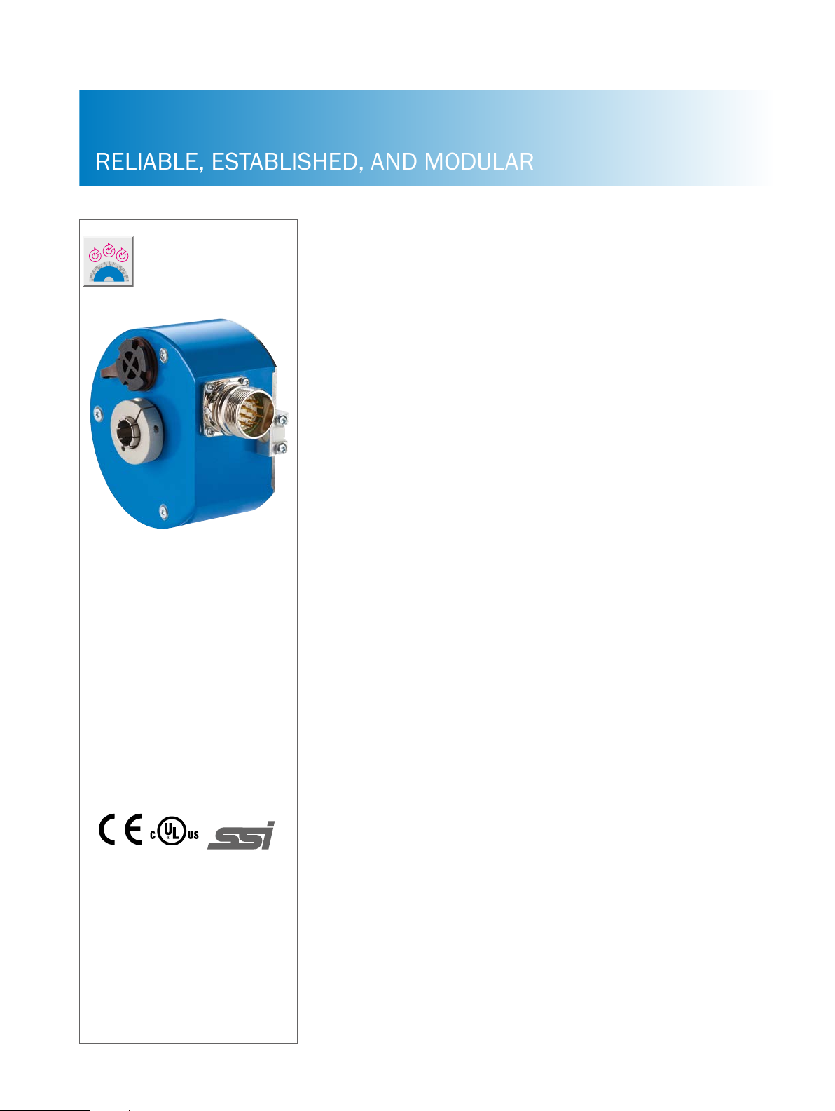
ATM90 SSI ABSOLUTE ENCODERS
RELIABLE, ESTABLISHED, AND MODULAR
Product description
The ATM90 with SSI data interface
complements the through hollow shaft
variants in the ATM60 product family.
The ATM90 operates reliably even under
harsh ambient conditions. Its rugged
mechanical design ensures maximum reliability and a long service life. Magnetic
singleturn scanning allows a maximum
resolution of up to 13 bits within one
revolution. The number of revolutions,
maximum of 13 bit, is output and
At a glance
• Extremely rugged, tried-and-tested
• Mechanical interface: through hollow
• Zero-set and preset functions via
absolute multiturn encoder with a
resolution of up to 26 bits
shaft with shallow installation depth
hardware or software
recorded using a mechanical and almost
completely wear-free transmission. This
means that the ATM90 can be operated
without a battery. A shallow installation
depth of 60 mm combined with high
shock and vibration resistance enable
the ATM90 to be used in applications
with high mechanical stress and distinct
climate uctuations
• Electrical interface: SSI with gray or
binary code type
• Electronically adjustable, congurable
resolution
• Magnetic scanning
G
More information
Fields of application . . . . . . . . . . .G-437
Detailed technical data. . . . . . . . .G-437
Type code. . . . . . . . . . . . . . . . . . . .G-438
Ordering information. . . . . . . . . . .G-439
Dimensional drawings . . . . . . . . .G-440
PIN assignment. . . . . . . . . . . . . . .G-441
Recommended accessories. . . . .G-442
Your benets
• Fewer variants are required since one
freely programmable encoder offers
all singleturn and multiturn resolutions
• Easy setup due to various electrical
connection adapters (cable, M23)
• Maintenance-free encoder, long
service life
• Quick commissioning using the zero
set/preset function either at the press
of the button on the device or via
software
• Increased productivity due to highly
reliable shock and vibration resistance
• Worldwide availability and service
ensure quick and reliable customer
service
G-436
ENCODERS | SICK 8015560/2015-09-01
Subject to change without notice
Page 2

Fields of application
• Measurement of absolute position in various machines
and system such as wind power and solar plants, material
Detailed technical data
Performance
ABSOLUTE ENCODERS ATM90 SSI
transport equipment, textile machines, packaging systems,
rollers, harbor facilities, printing machines
Max. number of steps per revolution
Max. number of revolutions
Resolution
Error limits
Repeatability
Measurement step
Initialization time
1)
Valid positional data can be read once this time has elapsed.
Interfaces
Electrical interface
Signal wire
Interface signals
Clock frequency
Set (electronic adjustment)
CW/CCW (counting sequence when turn-
ing)
Conguration data
1)
For higher clock frequencies, choose synchronous SSI.
2)
Min. LOW level (Clock +): 500 ns.
≤ 8,192
≤ 8,192
13 x 12 or 12 x 13 bit
± 0.25°
0.1°
0.043°
1,050 ms
SSI
Potential-free with a 12-pin M23 male connector for the housing or a 12-wire cable
Clock +, Clock -, Data +, Data- 1)
Programming interface: RS-422
1 MHz
H active (L = 0 - 4.7 V, H = 10 - Us V)
L active (L = 0 - 1.5 V, H = 2.0 - Us V)
Number of steps per revolution
Number of revolutions
Code type
Electronic adjustment
1)
2)
G
Electrical data
Operating voltage range
Max. power consumption without load
Code type
Code sequence
Reverse polarity protection
MTTFd: mean time to dangerous failure
1)
This product is a standard product and does not constitute a safety component as dened in the Machinery Directive. Calculation based on nominal load of devices,
average ambient temperature 40 °C, frequency of use 8,760 h/a. All electronic failures are considered hazardous. For more information, see document no.
8015532.
Subject to change without notice
10 V ... 32 V
≤ 0.8 W
Gray, binary
CW/CCW
m
150 years (EN ISO 13849-1)
1)
ENCODERS | SICK8015560/2015-09-01
G-437
Page 3
ATM90 SSI ABSOLUTE ENCODERS
Mechanical data
Shaft diameter
Through hollow shaft 12, 16 mm and 1/2"
Shaft material
Flange material
Housing material
1)
Mass
Start up torque at 20 °C
Operating torque at 20 °C
Max. angular acceleration
Max. operating speed
2)
Rotor moment of inertia
Bearing lifetime
1)
Relates to devices with cable outlet.
2)
Take into account self-warming of 3.3 K per 1,000 rpm when designing operating temperature range
Ambient data
Stainless steel
Aluminum
Aluminum
0.8 kg
0.5 Ncm
0.4 Ncm
≤ 600,000 rad/s²
2,000 rpm
152.77 gcm²
3.6 x 10⁹ revolutions
G
EMC
Enclosure rating
Permissible relative humidity
Operating temperature range
Storage temperature range
Resistance to shocks
Resistance to vibrations
1)
When mating connector is inserted.
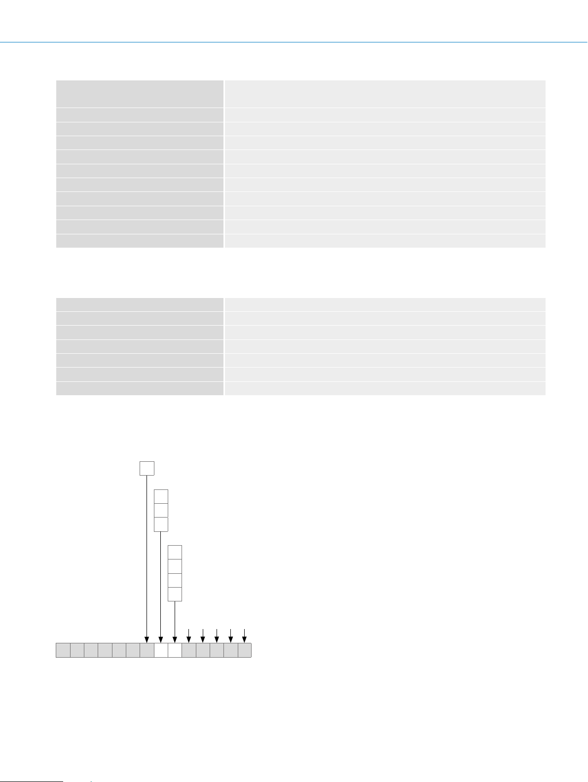
Type code
Electrical interface
A
According to EN 61000-6-2 and EN 61000-6-3
IP 65 with shaft seal (acc. to IEC 60529)
98%
–20 °C ... +70 °C
–40 °C ... +100 °C, without packaging
100 g /6 ms (according to EN 60068-2-27)
20 g / 10 Hz - 2,000 Hz (according to EN 60068-2-6)
10 V...32 V, SSI/RS422
1)
Mechanical design
Through hollow shaft, Ø 12 mm
T
Through hollow shaft Ø 1/2"
U
Through hollow shaft, Ø 16 mm
X
Connection type
Male connector M23, 12-pin, radial outlet
A
Cable, 12-wire, radial outlet, 1.5 m
K
Cable, 12-wire, radial outlet, 3.0 m
L
Cable, 12-wire, radial outlet, 5.0 m
M
Resolution can be programmed by the customer using the programming tool PGT 01
Factory setting:12 bit singleturn x 12 bit multiturn
1),2)
A T M 9 0 – A 1 2 x 1 2
1)
Ex-works conguration: 4,096 steps x 4,096 revolutions, Gray-Code, Set = 0. Other congurations on request.
2)
Maximum permissible resolution: 25 bit (12 bit singleturn x 13 bit multiturn or 13 bit singleturn x 12 bit multiturn).
G-438
ENCODERS | SICK 8015560/2015-09-01
Subject to change without notice
Page 4

Ordering information
Through hollow shaft
• Electrical interface: 10 V ... 32 V, SSI
• Number of steps: ≤ 4,096
• Resolution: 4,096 x 4,096
• Programmable: l
Shaft diameter Connection type Type Part no.
1/2"
12 mm
16 mm
ABSOLUTE ENCODERS ATM90 SSI
Cable, 12-wire, radial, 1.5 m ATM90-AUK12X12 1030035
Cable, 12-wire, radial, 3 m ATM90-AUL12X12 1030036
Cable, 12-wire, radial, 5 m ATM90-AUM12X12 1030037
M23 male connector, 12-pin, radial ATM90-AUA12X12 1030034
Cable, 12-wire, radial, 1.5 m ATM90-ATK12X12 1030031
Cable, 12-wire, radial, 3 m ATM90-ATL12X12 1030032
Cable, 12-wire, radial, 5 m ATM90-ATM12X12 1030033
M23 male connector, 12-pin, radial ATM90-ATA12X12 1030030
Cable, 12-wire, radial, 1.5 m ATM90-AXK12X12 1030039
Cable, 12-wire, radial, 3 m ATM90-AXL12X12 1030040
Cable, 12-wire, radial, 5 m ATM90-AXM12X12 1030041
M23 male connector, 12-pin, radial ATM90-AXA12X12 1030038
G
Subject to change without notice
ENCODERS | SICK8015560/2015-09-01
G-439
Page 5

ATM90 SSI ABSOLUTE ENCODERS
15
9
15.5
2
Dimensional drawings (dimensions in mm)
(0.35)
82.5 (3.25)
19
(0.75)
(0.59)
1
15
(0.59)
R
Ø 8
(0.31)
24 (0.94)
(1.26)
max. Ø 32
Ø Xh7
(0.61)
15.5
(0.61)
max. 18
(0.71)
min. 5
(0.20)
(1.59)
±0.1
40.5
A
G
Ø 93 (3.66)
Ø Xh7
General tolerances according to DIN ISO 2768-mk
1 Min. bend radius 40 mm
2 Encoder stator coupling through customer’s Ø 6 mm cylindrical pin, DIN EN 28734
47.5 (1.87)
60 (2.36)
min. 60 (2.36)
G-440
ENCODERS | SICK 8015560/2015-09-01
Subject to change without notice
Page 6

ABSOLUTE ENCODERS ATM90 SSI
PIN assignment
PIN Signal Wire colors (cable outlet) Explanation
1 GND Blue Ground connection
2 Data + White Interface signals
3 Clock + Yellow Interface signals
4 R x D + Gray RS-422 programming cable
5 R x D – Green RS-422 programming cable
6 T x D + Pink RS-422 programming cable
7 T x D – Black RS-422 programming cable
8 U
9 SET Orange Electronic adjustment
10 Data – Brown Interface signals
11 Clock – Violet Interface signals
12 V/¯R Orange/black Sequence in direction of rotation
S
Screen Housing potential
Red Operating voltage
View of M23 male device connector on encoder
V/¯R This input programs the counting direction for the encoder. When it is not connected, this input is set to HIGH. If the encoder
shaft is rotated clockwise (to the right) as viewed when facing the shaft, it counts in ascending order. If it should count in ascending order when the shaft is rotated counterclockwise (to the left), then this connection must be permanently set to LOW
level (GND).
SET This input is for electronic zeroing. If the SET cable is set to U
for more than 100 ms, the mechanical position corresponds to
S
the O value, i.e., the predetermined SET value.
G
Subject to change without notice
ENCODERS | SICK8015560/2015-09-01
G-441
Page 7

ATM90 SSI ABSOLUTE ENCODERS
Recommended accessories
Connectivity
Plug connectors and cables
Connecting cables with female connector
G
Figure Brief description Length
Type Part no.
of
cable
1.5 m DOL-2312-G1M5MA1 2029200
Head A: female connector, M23, 12-pin, straight
Head B: cable
Cable: suitable for drag chain, PUR, shielded, 4 x 2 x 0.25 mm² + 2 x 0.5 mm²
+ 2 x 0.14 mm², Ø 7.8 mm
Dimensional drawings g page K-725
3 m DOL-2312-G03MMA1 2029201
5 m DOL-2312-G05MMA1 2029202
10 m DOL-2312-G10MMA1 2029203
20 m DOL-2312-G20MMA1 2029204
30 m DOL-2312-G30MMA1 2029205
Female connectors (ready to assemble)
Figure Brief description Type Part no.
Head A: female connector, M23, 12-pin, straight, shielded, for cable diameter 5.5 mm ...
10.5 mm
Head B: -
Operating temperature: –20 °C ... +130 °C
Head A: female connector, M23, 12-pin, straight, shielded, for cable diameter 5.5 mm ...
10.5 mm
Head B: Operating temperature:
–40 °C ... +125 °C
Head A: female connector, M23, 12-pin, angled, shielded, for cable diameter 4.2 mm ...
6.6 mm
Head B: -
Operating temperature: –20 °C ... +130 °C
Head A: female connector, M23, 21-pin, straight, shielded, for cable diameter 5.5 mm ...
12 mm
Head B: -
DOS-2312-G 6027538
DOS-2312-G02
DOS-2312-W01 2072580
DOS-2321-G 6027539
2077057
Dimensional drawings g page K-725
Cables (ready to assemble)
Figure Brief description Length
Head A: cable
Head B: cable
Cable: suitable for drag chain, PUR, halogen-free, shielded, 4 x 2 x 0.15 mm²,
Ø 5.6 mm
Head A: cable
Head B: cable
Cable: PUR, shielded, 4 x 2 x 0.25 mm² + 2 x 0.5 mm² + 1 x 0.14 mm²,
Ø 7.5 mm
Head A: cable
Head B: cable
Cable: suitable for drag chain, PUR, halogen-free, shielded, 4 x 2 x 0.25 mm² +
2 x 0.5 mm² + 2 x 0.14 mm², Ø 7.8 mm
Head A: cable
Head B: cable
Cable: suitable for drag chain, PUR, halogen-free, shielded, UV and saltwater-resistant, 4 x 2 x 0.25 mm² + 2 x 0.5 mm² + 2 x 0.14 mm², Ø 7.8 mm
G-442
ENCODERS | SICK 8015560/2015-09-01
of
cable
By the
meter
By the
meter
By the
meter
By the
meter
Type Part no.
LTG-2308-MWENC 6027529
LTG-2411-MW 6027530
LTG-2512-MW 6027531
LTG-2612-MW 6028516
Subject to change without notice
Page 8

ABSOLUTE ENCODERS ATM90 SSI
Male connectors (ready to assemble)
Figure Brief description Type Part no.
Head A: male connector, M23, 12-pin, straight, shielded, for cable diameter 5.5 mm ...
10.5 mm
Head B: -
Operating temperature: –20 °C ... +130 °C
Head A: male connector, M23, 12-pin, straight, for cable diameter 5.5 mm ... 10.5 mm
Head B: Operating temperature:
–40 °C ... +125 °C
Dimensional drawings g page K-725
Other accessories
Programming and conguration tools
Figure Brief description Type Part no.
Programming tool for ATM60, ATM90 and KH53 SSI PGT-01-S 1030111
- For additional accessories, please see page K-668 onwards
STE-2312-G 6027537
STE-2312-G01 2077273
G
Subject to change without notice
ENCODERS | SICK8015560/2015-09-01
G-443
 Loading...