

Page 1
ATM90 PROFIBUS ABSOLUTE ENCODERS
RELIABLE, ESTABLISHED, AND MODULAR
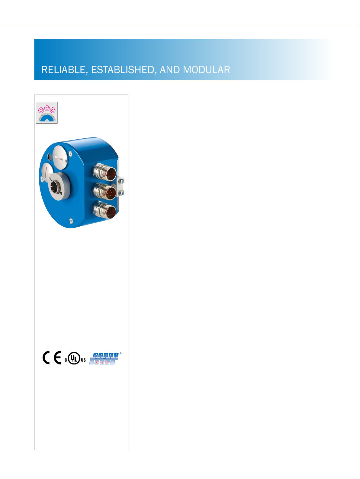
Product description
The ATM90 PROFIBUS complements
the through hollow shaft variants in
the ATM60 product family. The ATM90
operates reliably even under harsh ambient conditions. Its rugged mechanical
design ensures maximum reliability and
a long service life. Magnetic singleturn
scanning allows a maximum resolution
of up to 13 bits within one revolution.
The number of revolutions, maximum
of 13 bit, is output and recorded using
At a glance
• Extremely rugged, tried-and-tested
absolute multiturn encoder with a
resolution of up to 26 bits
• Mechanical interface: through hollow
shaft with shallow installation depth
• Zero-set and preset functions via
hardware or software
a mechanical and almost completely
wear-free transmission. This means that
the ATM90 can be operated without a
battery. A shallow installation depth of
60 mm combined with high shock and
vibration resistance enable the ATM90
to be used in applications with high
mechanical stress and distinct climate
uctuations
• Electrical interface: PROFIBUS DP as
per IEC61158 / RS-485 , electrically
isolated
• Electronically adjustable, congurable
resolution
• Magnetic scanning
G
More information
Fields of application . . . . . . . . . . .G-445
Detailed technical data. . . . . . . . .G-445
Type code. . . . . . . . . . . . . . . . . . . .G-446
Ordering information. . . . . . . . . . .G-447
Dimensional drawings . . . . . . . . .G-447
PIN assignment. . . . . . . . . . . . . . .G-449
Recommended accessories. . . . .G-451
Your benets
• Fewer variants are required since one
freely programmable encoder offers
all singleturn and multiturn resolutions
• Easy setup due to various electrical
connection adapters (cable, M23)
• Maintenance-free encoder, long
service life
• Quick commissioning using the zero
set/preset function either at the press
of the button on the device or via
software
• Increased productivity due to highly
reliable shock and vibration resistance
• Worldwide availability and service
ensure quick and reliable customer
service
G-444
ENCODERS | SICK 8015560/2015-09-01
Subject to change without notice
Page 2

Fields of application
• Measurement of absolute position in various machines
and system such as wind power and solar plants, material
Detailed technical data
Performance
ABSOLUTE ENCODERS ATM90 PROFIBUS
transport equipment, textile machines, packaging systems,
rollers, harbor facilities, printing machines
Max. number of steps per revolution
Max. number of revolutions
Resolution
Error limits
Repeatability
Measurement step
Initialization time
1)
Valid positional data can be read once this time has elapsed.
Interfaces
Electrical interface
Bus interface
Set (electronic adjustment)
Data protocol
Address setting
Data transmission rate (baud rate)
Status information
Bus termination
1)
EN 50 170-2.
2)
DIN 19245 Part 1-3.
3)
Electrically isolated through optocoupler.
4)
Should only be connected in the nal device.
Electrical data
≤ 8,192
8,192
13 bit x 13 bit
± 0.25°
0.1°
0.043°
1,250 ms
PROFIBUS
PROFIBUS DP, RS–485 1) 2)
Via PRESET pushbutton or protocol
Prole for encoder (07hex) – Class 2
0 ... 127, DIP switch or protocol
9.6 kBaud to 12 Mbaud, autodetect
LED green (running), LED red (bus activity)
DIP switch
1)
3)
4)
G
Connection type
Operating voltage range
Max. power consumption without load
Reverse polarity protection
MTTFd: mean time to dangerous failure
1)
This product is a standard product and does not constitute a safety component as dened in the Machinery Directive. Calculation based on nominal load of devices,
average ambient temperature 40 °C, frequency of use 8,760 h/a. All electronic failures are considered hazardous. For more information, see document no.
8015532.
Subject to change without notice
Bus adapter with 3 x M14 screw xings
Bus adapter with 3 cable screw xings
10 V ... 32 V
≤ 2 W
m
150 years (EN ISO 13849-1)
1)
ENCODERS | SICK8015560/2015-09-01
G-445
Page 3

ATM90 PROFIBUS ABSOLUTE ENCODERS
Mechanical data
Shaft diameter
Through hollow shaft 12, 16 mm and 1/2"
Shaft material
Flange material
Housing material
1)
Mass
Connector outlet 0.6 kg
Cable outlet 0.8 kg
Start up torque at 20 °C
Operating torque at 20 °C
Max. angular acceleration
Max. operating speed
2)
Rotor moment of inertia
Bearing lifetime
1)
Relates to devices with cable outlet.
2)
Take into account self-warming of 3.3 K per 1,000 rpm when designing operating temperature range
Ambient data
Stainless steel
Aluminum
Aluminum
0.5 Ncm
0.4 Ncm
≤ 600,000 rad/s²
3,000 rpm
153 gcm²
3,6 x 10⁹ revolutions
G
EMC
Enclosure rating
Permissible relative humidity
Operating temperature range
Storage temperature range
Resistance to shocks
Resistance to vibrations
Type code
Electrical interface
P
According to EN 61000-6-2 and EN 61000-6-3
IP 65 with shaft seal (acc. to IEC 60529)
98%
–20 °C ... +80 °C
–40 °C ... +100 °C, without packaging
6 g/20 ms (according to EN 60068-2-27)
20 g/ 10 Hz ... 2,000 Hz
PROFIBUS DP
Mechanical design
Through hollow shaft, Ø 12 mm
T
Through hollow shaft Ø 1/2"
U
Through hollow shaft, Ø 16 mm
X
Connection type
3 x M14 male connectors, 7-pin, radial outlet
F
3x screw xings for cable connection, metric M16 x 1.5, SW17
G
Resolution can be programmed by the customer
Factory setting:12 bit singleturn x 12 bit multiturn
A T M 9 0 – P x
G-446
ENCODERS | SICK 8015560/2015-09-01
Subject to change without notice
Page 4

Ordering information
82.5 (3.25)
A
Through hollow shaft
• Electrical interface: 10 V ... 32 V, PROFIBUS
• Number of steps: ≤ 8,192
• Resolution: 8,192 x 8,192
Shaft diameter Connection type Type Part no.
1/2"
12 mm
16 mm
Dimensional drawings (dimensions in mm)
Cable outlet
ABSOLUTE ENCODERS ATM90 PROFIBUS
Bus adapter with 3 cable screw xings ATM90-PUG13X13 1030046
Bus adapter with 3 x M14 screw xings ATM90-PUF13X13 1030043
Bus adapter with 3 cable screw xings ATM90-PTG13X13 1030045
Bus adapter with 3 x M14 screw xings ATM90-PTF13X13 1030042
Bus adapter with 3 cable screw xings ATM90-PXG13X13 1030047
Bus adapter with 3 x M14 screw xings ATM90-PXF13X13 1030044
58 (2.28)
(0.94)
max. 24
37 (1.46)
(1.59)
±0.1
40.5
D3
D2
Ø 93
(3.66)
D1
(1.42)
(1.02)
36
26
36 (1.42)
General tolerances according to DIN ISO 2768-mk
47.5 (1.87)
60 (2.36)
min. 60 (2.36)
max. 18
(0.71)
min. 5
(0.20)
X – 1
C – 1
G
C – 2
Subject to change without notice
ENCODERS | SICK8015560/2015-09-01
G-447
Page 5

ATM90 PROFIBUS ABSOLUTE ENCODERS
9
Connector outlet
1
D3
D2
(0.35)
X – 1
19
(0.75)
82.5 (3.25)
Ø 93 (3.66)
D1
General tolerances according to DIN ISO 2768-mk
1 Minimum bend radius 40 mm
16.6
max. 18
(0.65)
47.5
(1.87)
60 (2.36)
min. 80 (3.15)
(0.71)
A
min. 5
(0.20)
(1.59)
±0.1
40.5
C – 1
C – 2
20
(0.79)20(0.79)
+0.5
22
(0.87)
G
Hollow shaft D1 D2 D3
12 mm 12.0
1/2" 12.7
16 mm 16.0
C - 1
h7
h7
h7
F7
12.0
12.7
16.0
F7
F7
29.5
29.5
32.0
Stator coupling via cylindrical pin, (customer), Ø 6m6 as per
DIN EN ISO 8734
C - 2 Drive shaft (customer)
X - 1 3x screw xings for cable connection, metric M16 x 1.5, SW 17
A
When looking at the base plate (is used to dene the direction of
rotation)
G-448
ENCODERS | SICK 8015560/2015-09-01
Subject to change without notice
Page 6

ABSOLUTE ENCODERS ATM90 PROFIBUS
6
2
1
7
3
6
2
1
7
3
4
PIN assignment
PROFIBUS DP (in/out)
PIN Signal Explanation
1 RTS Request To Send 1)
2 A A cable PROFIBUS DP
3 N. C. Not connected
4 B B cable PROFIBUS DP
5 2M 0 V (potential free)
6 2P5 + 5 V (potential free)
7 N. C. Not connected
1)
Use for external bus terminations or to supply the sender/receiver with a optical ber transmission.
2)
Signal is optional, serves to detect the direction of an optical ber connection.
N. C. = Not connected.
5
4
2)
2)
U
S
PIN Signal Explanation
1 Us (24 V) Operating voltage
2 N. C. Not connected
3 GND (0 V) 0 V (Gnd)
4 N. C. Not connected
5 RTS Request To Send
6 N. C. Not connected
7 N. C. Not connected
1)
Signal is optional, serves to detect the direction of an optical ber connection.
N. C. = Not connected.
5
1)
G
Subject to change without notice
ENCODERS | SICK8015560/2015-09-01
G-449
Page 7

ATM90 PROFIBUS ABSOLUTE ENCODERS
Connection adapter
PIN Signal Explanation
1 Us (24 V) Operating voltage
2 GND (0 V) 0 V (Gnd)
3 B B cable PROFIBUS DP (out)
4 A A cable PROFIBUS DP (out)
5 B B cable PROFIBUS DP (in)
6 A A cable PROFIBUS DP (in)
7 2P5 + 5 V (potential free)
8 2M 0 V (potential free)
9 RTS Request To Send
1)
Use for external bus terminations or to supply the sender/receiver with a optical ber transmission.
2)
Signal is optional, serves to detect the direction of an optical ber connection.
RA1
RA2
TP8
TP6 TP4 TP2
TP11
R3
R4
R6
L5L4L3
L6
TP9
TP16TP15TP14 TP13
R1
TP10
R7
987654321
RTS
2M
R5
2P5
TP7 TP5
C3
IC1
ABA
TP3 TP1
TP17
B
L2
L1
TP18
S
U
0V
TP12
R2
C2
C1
U1
1)
1)
2)
G
G-450
ENCODERS | SICK 8015560/2015-09-01
Subject to change without notice
Page 8

Recommended accessories
Connectivity
Plug connectors and cables
Connecting cables with female connector
ABSOLUTE ENCODERS ATM90 PROFIBUS
Figure Brief description Length
Head A: female connector, M12, 5-pin, straight
Head B: cable
Cable: suitable for drag chain, PUR, halogen-free, shielded, 2 x 0.34 mm², Ø
8.0 mm
Dimensional drawings g page K-725
Connecting cables with male connector
Figure Brief description Length
Head A: male connector, M12, 5-pin, straight, B-coded
Head B: cable
Cable: suitable for drag chain, PUR, halogen-free, shielded, 2 x 0.34 mm², Ø
8.0 mm
Wire shielding: AL-PT foil, total shield, tin-plated C shield
Dimensional drawings g page K-725
Type Part no.
of
cable
5 m DOL-1205-G05MQ 6026006
10 m DOL-1205-G10MQ 6026008
12 m DOL-1205-G12MQ 6032636
15 m DOL-1205-G15MQ 6032637
20 m DOL-1205-G20MQ 6032638
30 m DOL-1205-G30MQ 6032639
50 m DOL-1205-G50MQ 6032861
Type Part no.
of
cable
5 m STL-1205-G05MQ 6026005
10 m STL-1205-G10MQ 6026007
12 m STL-1205-G12MQ 6032635
Female connectors (ready to assemble)
Figure Brief description Type Part no.
Head A: female connector, M12, 4-pin, straight, unshielded, for power supply, for cable
diameter 4 mm ... 6 mm
Head B: -
Head A: female connector, M12, 5-pin, straight, B-coded, shielded, for cable diameter
4 mm ... 9 mm
Head B: -
Head A: female connector, M14, 7-pin, straight, shielded, for cable diameter 4 mm ...
8 mm
Head B: -
Dimensional drawings g page K-725
DOS-1204-G 6007302
DOS-1205-GQ 6021353
DOS-1507-G 6027536
Cables (ready to assemble)
Figure Brief description Length
Type Part no.
of
cable
Head A: cable
Head B: cable
Cable: suitable for drag chain, PUR, shielded, 2 x 0.25 mm², Ø 8.0 mm
By the
meter
LTG-2102-MW 6021355
G
Subject to change without notice
ENCODERS | SICK8015560/2015-09-01
G-451
Page 9

ATM90 PROFIBUS ABSOLUTE ENCODERS
Other plug connectors and cables
Figure Brief description Type Part no.
Sales kit consisting of:
2 M14 male cable connectors, 7-pin (6027535)
1 M14 female cable connector, 7-pin (6027535)
Male connectors (ready to assemble)
Figure Brief description Type Part no.
Head A: male connector, M12, 5-pin, straight, B-coded, shielded, for cable diameter
4 mm ... 9 mm
Head B: -
Head A: male connector, M14, 7-pin, straight, shielded, for cable diameter 4 mm ...
8 mm
Head B: -
Dimensional drawings g page K-725
- For additional accessories, please see page K-668 onwards
DSC-1507-G 2029199
STE-1205-GQ 6021354
STE-1507-G 6027535
G
G-452
ENCODERS | SICK 8015560/2015-09-01
Subject to change without notice
Page 10

ABSOLUTE ENCODERS ATM90 PROFIBUS
G
Subject to change without notice
ENCODERS | SICK8015560/2015-09-01
G-453
 Loading...