

Page 1
ATM60 SSI ABSOLUTE ENCODERS
RELIABLE, ESTABLISHED, AND MODULAR
Product description
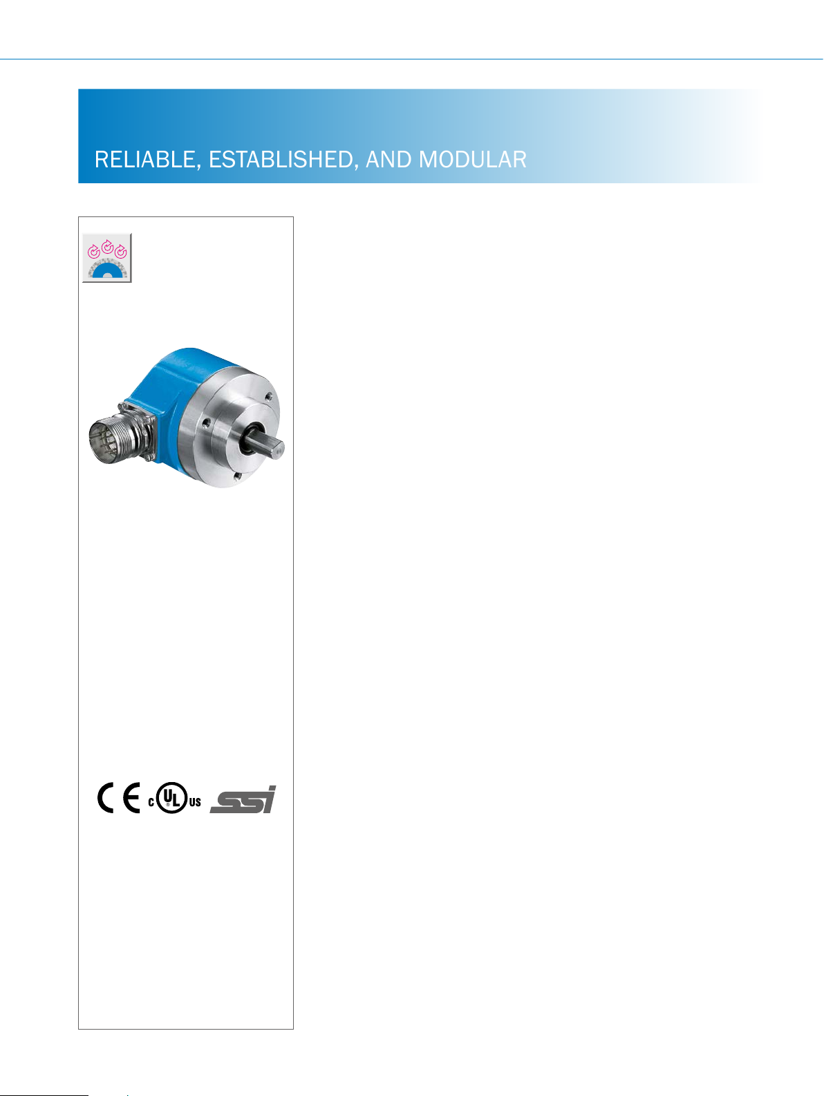
The ATM60 absolute multiturn encoder
from SICK has an SSI data interface and
provides reliable positional information
even in harsh ambient conditions, with a
resolution of up to 26 bits. This product
family, which is proven in its eld, is
based on the principle of magnetic measurement. The 13 bit singleturn range is
scanned by a sensor using permanent
magnetic elements. The 13 bit multiturn
At a glance
• Extremely rugged, tried-and-tested
• Mechanical interface: face mount
• Zero-set and preset functions via
absolute multiturn encoder with a
resolution of up to 26 bits
ange, servo ange, blind hollow
shaft, and extensive adapter accessories
hardware or software
range consists of a magnetic reduction
gear. Equipped with a zero set pushbutton, the encoder can be easily set to zero
or to any other user-programmed value
on site. Conguration of the SSI encoder
is easy using the RS422 interface. With
its magnetic scanning, rugged IP 67-rated housing and high level of resistance
to shock and vibration, the ATM60 is optimally suited for use in harsh conditions.
• Electrical interface: SSI with gray or
binary code type
• Electronically adjustable, congurable
resolution
• Round axis function (optional) also for
non-binary resolutions (per revolution)
and decimal numbers (number of
revolutions)
• Magnetic scanning
G
More information
Fields of application . . . . . . . . . . .G-399
Detailed technical data. . . . . . . . .G-399
Type code. . . . . . . . . . . . . . . . . . . .G-401
Ordering information. . . . . . . . . . .G-401
Dimensional drawings . . . . . . . . .G-402
PIN assignment. . . . . . . . . . . . . . .G-405
Mandatory accessories.........G-406
Recommended accessories. . . . .G-406
Your benets
• Fewer variants are required since one
freely programmable encoder offers
all singleturn and multiturn resolutions
• Easy setup due to various electrical
connection adapters (cable, M23)
• Maintenance-free encoder, long
service life
• Application exibility due to easily
interchangeable collets for the blind
‚
hollow shaft
• Quick commissioning using the zero
set/preset function either at the press
of the button on the device or via
software
• Increased productivity due to highly
reliable shock and vibration resistance
• Worldwide availability and service
ensure quick and reliable customer
service
G-398
ENCODERS | SICK 8015560/2015-09-01
Subject to change without notice
Page 2

Fields of application
• Measurement of absolute position in various machines
and system such as wind power and solar plants, material
Detailed technical data
Performance
ABSOLUTE ENCODERS ATM60 SSI
transport equipment, textile machines, packaging systems,
rollers, harbor facilities, printing machines
Max. number of steps per revolution
Max. number of revolutions
Resolution
Error limits
Repeatability
Measurement step
Initialization time
1)
Valid positional data can be read once this time has elapsed.
Interfaces
Electrical interface
Signal wire
Interface signals
Clock frequency
Set (electronic adjustment)
CW/CCW (counting sequence when turn-
ing)
Conguration data
1)
For higher clock frequencies, choose synchronous SSI.
2)
Min. LOW level (Clock +): 500 ns.
≤ 8,192
≤ 8,192
13 x 12 bit or 12 x 13 bit
± 0.25°
0.1°
0.043°
1,050 ms
SSI
Potential-free with a 12-pin M23 male connector for the housing or a 12-wire cable
Clock +, Clock -, Data +, Data- 1)
Programming interface: RS-422
1 MHz
H active (L = 0 - 4.7 V, H = 10 - Us V)
L active (L = 0 - 1.5 V, H = 2.0 - Us V)
Number of steps per revolution
Number of revolutions
Code type
Electronic adjustment
1)
2)
G
Electrical data
Operating voltage range
Max. power consumption without load
Code type
Code sequence
Supply voltage
Reverse polarity protection
MTTFd: mean time to dangerous failure
1)
This product is a standard product and does not constitute a safety component as dened in the Machinery Directive. Calculation based on nominal load of devices,
average ambient temperature 40 °C, frequency of use 8,760 h/a. All electronic failures are considered hazardous. For more information, see document no.
8015532.
Subject to change without notice
10 V ... 32 V
≤ 0.8 W
Gray, binary
CW/CCW
10 … 32 V
m
150 years (EN ISO 13849-1)
1)
ENCODERS | SICK8015560/2015-09-01
G-399
Page 3

G
ATM60 SSI ABSOLUTE ENCODERS
Mechanical data
Shaft diameter
Face mount ange 10 x 19 mm
Servo ange 6 x 10 mm
1)
Blind hollow shaft
Shaft material
Flange material
Housing material
2)
Mass
Face mount ange, servo ange 0.5 kg
Blind hollow shaft 0.4 kg
Start up torque at 20 °C
Face mount ange, servo ange 2.5 Ncm with shaft seal
Face mount ange, servo ange 0.5 Ncm without shaft seal
Blind hollow shaft 1.2 Ncm with shaft seal
Operating torque at 20 °C
Face mount ange, servo ange 1.8 Ncm with shaft seal
Face mount ange, servo ange 0.3 Ncm without shaft seal
Blind hollow shaft 0.8 Ncm with shaft seal
Permissible shaft loading
Face mount ange, servo ange 300 N radial
Permissible shaft movement of the drive
element, static/dynamic
Blind hollow shaft ± 0.3/ ± 0.1 mm radial
Max. angular acceleration
Operating speed
3)
Face mount ange, servo ange 6,000 rpm
Blind hollow shaft 3,000 rpm
Rotor moment of inertia
Face mount ange, servo ange 35 gcm²
Blind hollow shaft 55 gcm²
Bearing lifetime
1)
Order collets for 6, 8, 10, 12 and 14 mm or 1/4", 3/8" and 1/2" as separate extra accessories. No collets are necessary for 15 mm shaft diameter.
2)
Relates to devices with cable outlet.
3)
Take into account self-warming of 3.3 K per 1,000 rpm when designing operating temperature range
6, 8, 10, 12, 14, 15 mm and 1/4", 3/8", 1/2"
Stainless steel
Aluminum
Aluminum
50 N axial
± 0.5/ ± 0.2 mm axial
≤ 500,000 rad/s²
3.6 x 10⁹ revolutions
Ambient data
EMC
Enclosure rating (as per IEC 60529)
Permissible relative humidity
Operating temperature range
Storage temperature range
Resistance to shocks
Resistance to vibrations
1)
When mating connector is inserted.
G-400
ENCODERS | SICK 8015560/2015-09-01
According to EN 61000-6-2 and EN 61000-6-3
1)
IP 67, with shaft seal
IP 43, without shaft seal, not sealed on encoder ange
IP 65, without shaft seal, not sealed on encoder ange
98%
–20 °C ... +85 °C
–40 °C ... +100 °C, without packaging
100 g /6 ms (according to EN 60068-2-27)
20 g / 10 Hz - 2,000 Hz (according to EN 60068-2-6)
Subject to change without notice
Page 4
ABSOLUTE ENCODERS ATM60 SSI
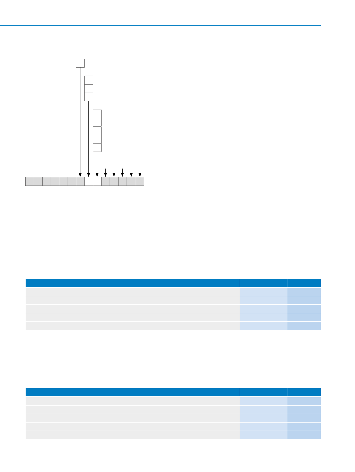
Type code
Electrical interface
10 V...32 V, SSI/RS422
A
Mechanical design
Solid shaft, servo ange, Ø 6 mm, length 10 mm
1
Solid shaft, face mount ange, Ø 10 mm, length 19 mm
4
Blind hollow shaft
A
Connection type
Male connector M23, 12-pin, radial outlet
A
Cable, 12-wire, radial outlet, 1.5 m
K
Cable, 12-wire, radial outlet, 3.0 m
L
Cable, 12-wire, radial outlet, 5.0 m
M
Cable, 12-wire, radial outlet, 10.0 m
N
Resolution can be programmed by the customer using the programming tool PGT 01
Factory setting:12 bit singleturn x 12 bit multiturn
A T M 6 0 – A 1 2 x 1 2
1)
Order collet for 6, 8, 10, 12 and 14 mm or 1/4", 3/8" and 1/2" as separate extra accessories (see recommended accessories). No collets are necessary for 15 mm
shaft diameter.
2)
Ex-works conguration: 4,096 steps x 4,096 revolutions, Gray-Code, Set = 0. Other congurations on request.
3)
Maximum permissible resolution: 25 bit (12 bit singleturn x 13 bit multiturn or 13 bit singleturn x 12 bit multiturn).
1)
2),3)
2)
Ordering information
Solid shaft, servo ange
• Shaft diameter: 6 mm, length 10 mm
• Electrical interface: 10 V ... 32 V, SSI
• Number of steps: ≤ 4,096
• Resolution: 4,096 x 4,096
• Programmable: l
Connection type Type Part no.
M23 male connector, 12-pin, radial ATM60-A1A12X12 1030005
Cable, 12-wire, radial, 1.5 m ATM60-A1K12X12 1030006
Cable, 12-wire, radial, 3 m ATM60-A1L12X12 1030007
Cable, 12-wire, radial, 5 m ATM60-A1M12X12 1030008
Cable, 12-wire, radial, 10 m ATM60-A1N12X12 1032925
Solid shaft, face mount ange
• Shaft diameter: 10 mm, length 19 mm
• Electrical interface: 10 V ... 32 V, SSI
• Number of steps: ≤ 4,096
• Resolution: 4,096 x 4,096
• Programmable: l
Connection type Type Part no.
M23 male connector, 12-pin, radial ATM60-A4A12X12 1030001
Cable, 12-wire, radial, 1.5 m ATM60-A4K12X12 1030002
Cable, 12-wire, radial, 3 m ATM60-A4L12X12 1030003
Cable, 12-wire, radial, 5 m ATM60-A4M12X12 1030004
Cable, 12-wire, radial, 10 m ATM60-A4N12X12 1032915
G
Subject to change without notice
ENCODERS | SICK8015560/2015-09-01
G-401
Page 5
ATM60 SSI ABSOLUTE ENCODERS
Ø 59.5 (2.34)
2B
20°
Blind hollow shaft
• Shaft diameter: 6 mm, 8 mm, 10 mm, 12 mm, 14 mm, 15 mm 1/4", 3/8", 1/2" (order collets for 6, 8, 10, 12 and 14 mm or
1/4", 3/8" and 1/2" as separate accessories. No collets are necessary for 15 mm shaft diameter).
• Electrical interface: 10 V ... 32 V, SSI
• Number of steps: ≤ 4,096
• Resolution: 4,096 x 4,096
• Programmable: l
Connection type Type Part no.
M23 male connector, 12-pin, radial ATM60-AAA12X12 1030009
Cable, 12-wire, radial, 1.5 m ATM60-AAK12X12 1030010
Cable, 12-wire, radial, 3 m ATM60-AAL12X12 1030011
Cable, 12-wire, radial, 5 m ATM60-AAM12X12 1030012
Cable, 12-wire, radial, 10 m ATM60-AAN12X12 1033169
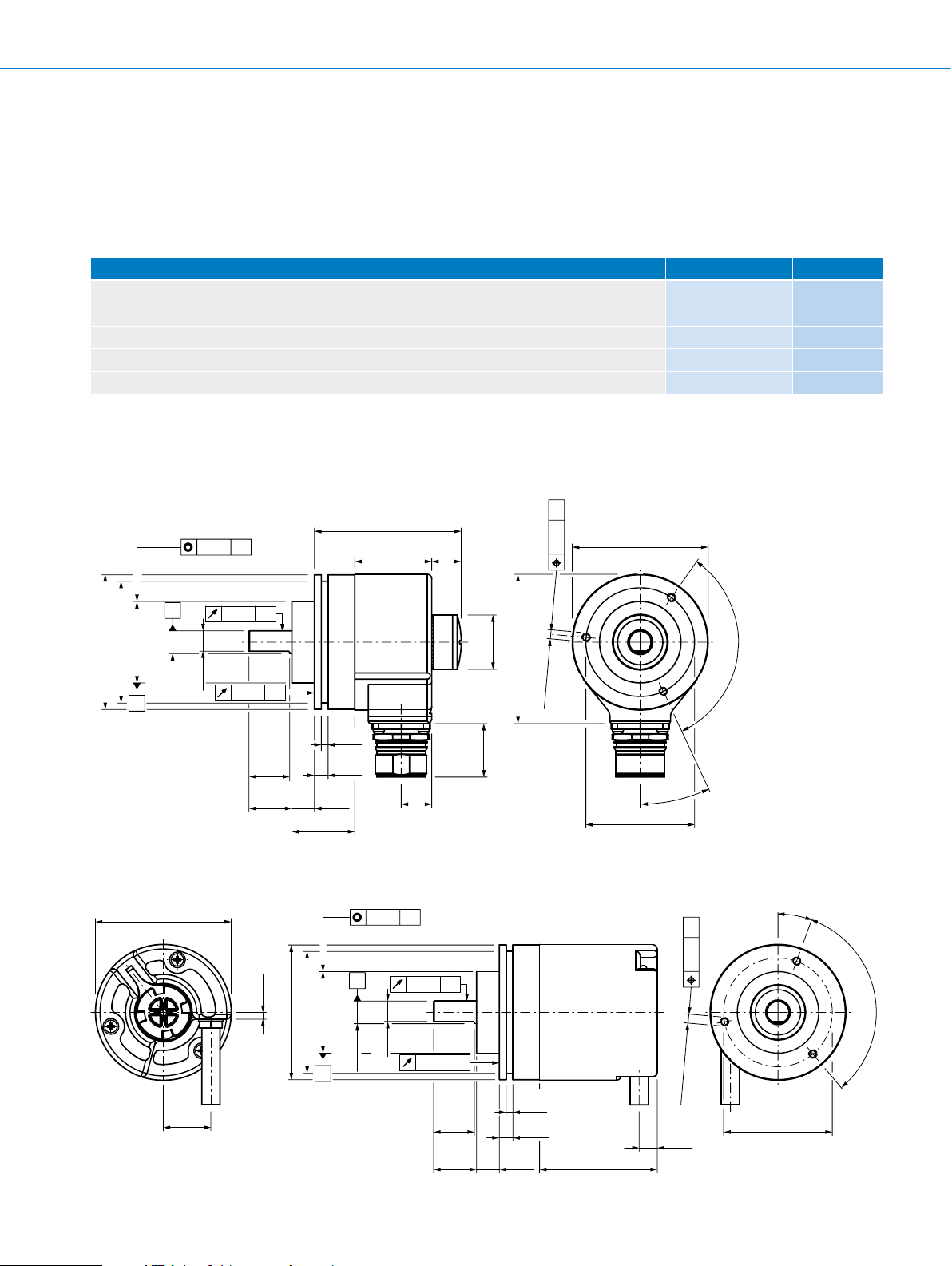
Dimensional drawings (dimensions in mm)
Face mount ange, male connector
G
64.8 (2.55)
Ø 53.8 (2.12)
Ø 36 f8 (1.42)
B
A
(0.39)
Ø 10 f6
Ø 0.2 A
9
(0.35)
0.1 A
0.2 A
(0.71)
19
(0.75)
18
±1
(0.39)
27.8 (1.09)
(0.12)
(0.24)
10
34 (1.34)
3
6
General tolerances according to DIN ISO 2768-mk
Face mount ange, cable
Ø 60 (2.36)
3
(0.12)
(2.12)
Ø 0.2 A
A
13.5
(0.53)
0.1 A
13
(0.51)
Ø 24
(0.94)
24 (0.94)
66 (2.60)
3 x M4
Ø 0.
deep
(0.28)
7
Ø 60 (2.36)
±0.1
Ø 48
2 x 120°
25°
(1.89)
Ø 0.2B
G-402
3 x 120°
(0.39)
Ø 10 f6
9
(0.35)
0.2 A
18
(0.71)
19
(0.75)
deep
3 x M4
3
(0.12)
6
(0.24)
±1
10
(0.39)
52 (2.05)
(0.28)
7
8
(0.31)
±0.1
Ø 48
(1.89)
Subject to change without notice
Ø 59.5 (2.34)
Ø 53.8
Ø 36 f8 (1.42)
B
21
(0.83)
ENCODERS | SICK 8015560/2015-09-01
Page 6

General tolerances according to DIN ISO 2768-mk
64.8
3
3 x 120°
Servo ange, male connector
ABSOLUTE ENCODERS ATM60 SSI
(2.55)
34 (1.34)
Ø 0.2 A
0.2 A
(0.12)
(0.12)
4
(0.16)
3
0.1 A
A
Ø 58 (2.28)
Ø 59.5 (2.34)
Ø 51.5 (2.03)
Ø 50 f8 (1.97)
(0.24)
Ø 6 f6
B
10
(0.39)
±1
27.8 (1.09)
13.5
(0.53)
General tolerances according to DIN ISO 2768-mk
Servo ange, cable
Ø 60 (2.36)
Ø 0.2 A
13
(0.51)
Ø 24
(0.94)
(0.94)
24
27.8 (1.09) 52 (2.05)
3 x 120°
Ø 60 (2.36)
Ø 42
25°
±0.1
(1.65)
deep
3 x M4
(0.28)
7
Ø 0.2A
(2.60)
66
70°
3
(0.12)
Ø 58 (2.28)
Ø 51.5 (2.03)
Ø 59.5 (2.34)
Ø 50 f8 (1.97)
B
21
(0.83)
0.2 A
General tolerances according to DIN ISO 2768-mk
0.1 A
A
(0.24)
Ø 6 f6
±1
10
(0.39)
(0.16)
(1.65)
±0.1
Ø 42
8
(0.31)
7
(0.28)
3 x M4
deep
Ø 0.2 B
4
3
(0.12)
3
(0.12)
69.8 (2.75)
G
Subject to change without notice
ENCODERS | SICK8015560/2015-09-01
G-403
Page 7

ATM60 SSI ABSOLUTE ENCODERS
73.3 (2.89) 13.8
Ø 60 (2.36)
(0.13)
91.3 (3.59)
20°
Blind hollow shaft, male connector
13.5
(0.53)
(0.54)
3.8
(0.15)
2
Ø XF7
Ø 59.5 (2.34)
max. 30 (1.18)
min. 15 (0.59)
Installation edge
on stator coupling
34 (1.34)
General tolerances according to DIN ISO 2768-mk
Blind hollow shaft, cable
3.8
(0.15)
2
(0.08)
Ø 24 (0.94)
Ø 66 (2.66)
24 (0.94)
20 (0.79)
72 (2.83)
Ø 63 (2.48)
52 (2.05)
Ø 3.2
20°
+0,1
72 (2.83)
Ø 63 (2.48)
G
Ø XF7
Ø 60 (2.36)
Ø 59.5 (2.34)
45°
21
(0.83)
max. 30 (1.18)
min. 15 (0.59)
Installation edge
on stator coupling
General tolerances according to DIN ISO 2768-mk
8
(0.31)
20 (0.79)
Ø 3.2
+0,1
(0.13)
G-404
ENCODERS | SICK 8015560/2015-09-01
Subject to change without notice
Page 8

ABSOLUTE ENCODERS ATM60 SSI
PIN assignment
PIN Signal Wire colors (cable outlet) Explanation
1 GND Blue Ground connection
2 Data + White Interface signals
3 Clock + Yellow Interface signals
4 R x D + Gray RS-422 programming cable
5 R x D – Green RS-422 programming cable
6 T x D + Pink RS-422 programming cable
7 T x D – Black RS-422 programming cable
8 U
9 SET
S
1)
10 Data – Brown Interface signals
11 Clock – Violet Interface signals
12 V/¯R
2)
Screen Housing potential
1)
SET = This input activates the electronic zero set. If the SET cable is set to US for more than 100 ms, the mechanical position corresponds to the O value, i.e., the
predetermined SET value.
2)
V/¯R = Forwards/Reverse: This input programs the counting direction for the encoder. When it is not connected, this input is set to HIGH. If the encoder shaft is rotat-
ed clockwise (to the right) as viewed when facing the shaft, it counts in ascending order. If it should count in ascending order when the shaft is rotated counterclockwise (to the left), then this connection must be permanently set to LOW level (GND).
Red Operating voltage
Orange Electronic adjustment
Orange/black Sequence in direction of rotation
View of M23 male device connector on encoder
G
Subject to change without notice
ENCODERS | SICK8015560/2015-09-01
G-405
Page 9
ATM60 SSI ABSOLUTE ENCODERS
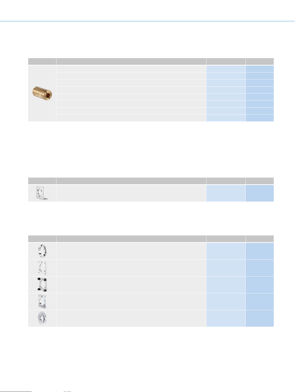
Mandatory accessories
Shaft adaptation
Collets and clamping rings
Figure Brief description Type Part no.
Collet for blind hollow shaft, shaft diameter 6 mm, external diameter 15 mm SPZ-006-AD-A 2029174
Collet for blind hollow shaft, shaft diameter 8 mm, external diameter 15 mm SPZ-008-AD-A 2029176
Collet for blind hollow shaft, shaft diameter 10 mm, external diameter 15 mm SPZ-010-AD-A 2029178
Collet for blind hollow shaft, shaft diameter 12 mm, external diameter 15 mm SPZ-012-AD-A 2029179
Collet for blind hollow shaft, shaft diameter 14 mm, external diameter 15 mm SPZ-014-AD-A 2048863
Collet for blind hollow shaft, shaft diameter 1/2" (12.7 mm), external diameter 15 mm SPZ-1E2-AD-A 2029180
Collet for blind hollow shaft, shaft diameter 1/4" (6.35 mm), external diameter 15 mm SPZ-1E4-AD-A 2029175
Collet for blind hollow shaft, shaft diameter 3/8" (9.525 mm), external diameter 15 mm SPZ-3E8-AD-A 2029177
Dimensional drawings g page K-725
Recommended accessories
Mounting systems
G
Mounting brackets and plates
Mounting bracket
Figure Brief description Type Part no.
Mounting bracket for encoder with centering hub 36 mm, including mounting kit for face
mount ange
Dimensional drawings g page K-725
BEF-WF-36 2029164
Flanges
Flange plate
Figure Brief description Type Part no.
Flange adapter, adaptation of face mount ange with 36 mm centering hub to 50 mm
servo ange, aluminum, including 3 at head screws M4 x 10
Flange adapter, adaptation of face mount ange with 36 mm centering hub to 60 mm
square mounting plate, aluminum, including 3 at head screws M4 x 10
Flange adapter, adaptation of face mount ange with 36 mm centering hub to 58 mm
square mounting plate with shock absorbers, aluminum
Flange adapter, adaptation of face mount ange with 36 mm centering hub to 63 mm
square mounting plate, aluminum, including 3 at head screws M4 x 10
BEF-FA-036-050 2029160
BEF-FA-036-060REC 2029162
BEF-FA-036-060RSA 2029163
BEF-FA-036-063REC 2034225
Flange adapter, adaptation of face mount ange with 36 mm centering hub to 100 mm
servo ange with 60 mm centering hub, aluminum
Dimensional drawings g page K-725
G-406
ENCODERS | SICK 8015560/2015-09-01
BEF-FA-036-100 2029161
Subject to change without notice
Page 10

ABSOLUTE ENCODERS ATM60 SSI
Other mounting accessories
Measuring wheels and measuring wheel systems
Figure Brief description Type Part no.
Measuring wheel with smooth plastic surface (Hytrel) for 10 mm solid shaft, circumference 200 mm
Measuring wheel with ridged plastic surface (Hytrel) for 10 mm solid shaft, circumference 200 mm
Measuring wheel with smooth plastic surface (Hytrel) for 10 mm solid shaft, circumference 500 mm
Measuring wheel with O-ring (NBR70) for 6 mm solid shaft, circumference 200 mm BEF-MR006020R 2055222
Measuring wheel with O-ring (NBR70) for 6 mm solid shaft, circumference 300 mm BEF-MR006030R 2055634
Measuring wheel with O-ring (NBR70) for 10 mm solid shaft, circumference 300 mm BEF-MR010030R 2049278
Dimensional drawings g page K-725
BEF-MR-010020 5312988
BEF-MR-010020G 5318678
BEF-MR-010050 5312989
Mounting bell
Figure Brief description Type Part no.
Mounting bell for encoders with a servo ange, centering hub 50 mm, including mounting kit
Dimensional drawings g page K-725
BEF-MG-50 5312987
Servo clamps
Figure Brief description Type Part no.
Half-shell servo clamps (2 pcs.) for servo anges with a 50 mm centering hub BEF-WG-SF050 2029165
Servo clamps, large, for servo anges (clamps, eccentric fastener), 3 pcs., without
mounting material
Dimensional drawings g page K-725
BEF-WK-SF 2029166
Miscellaneous
Figure Brief description Type Part no.
Mounting kit for servo ange encoder on the bearing block, 1 bar coupling SKPS
1520 06/06 1 hexagon socket wrench SW1.5 DIN 911, 3 mounting eccentric BEMN
1242 49 3 screws M4 x 10 DIN 912, 1 hexagon socket wrench SW3 DIN 911
Bearing block for hollow shaft encoder, including xing screws BEF-FA-B12-010 2042728
Bearing block for servo and face mount ange encoder BEF-FA-LB1210 2044591
Dimensional drawings g page K-725
BEF-MK-LB 5320872
G
Subject to change without notice
ENCODERS | SICK8015560/2015-09-01
G-407
Page 11

G
ATM60 SSI ABSOLUTE ENCODERS
Shaft couplings
Figure Brief description Type Part no.
Bellows coupling, shaft diameter 6 mm / 6 mm, maximum shaft offset: radial
± 0.25 mm, axial ± 0.4 mm, angular ± 4°; max. speed 10,000 rpm, –30 °C ... +120 °C,
max. torque 80 Ncm; material: stainless steel bellows, aluminum hub
Bellows coupling, shaft diameter 6 mm / 10 mm, maximum shaft offset: radial
± 0.25 mm, axial ± 0.4 mm, angular ± 4°; max. speed 10,000 rpm, –30 °C ... +120 °C,
max. torque 80 Ncm; material: stainless steel bellows, aluminum hub
Bellows coupling, shaft diameter 10 mm/10 mm; maximum shaft offset: radial
± 0.25 mm, axial ± 0.4 mm, angular ± 4°; max. revolutions 10,000 rpm, -30° to
+120 °C, max. torque 80 Ncm; material: stainless steel bellows, aluminum clamping
hubs
Bellows coupling, shaft diameter 10 mm/12 mm; maximum shaft offset: radial
± 0.25 mm, axial ± 0.4 mm, angular ± 4°; max. revolutions 10,000 rpm, -30° to
+120 °C, max. torque 80 Ncm; material: stainless steel bellows, aluminum clamping
hubs
Bar coupling, shaft diameter 6 mm / 6 mm, maximum shaft offset: radial ± 0.3 mm,
axial ± 0.2 mm, angle ± 3°; max. speed 10,000 rpm, -10° to +80 °C, max. torque
80 Ncm; material: ber-glass reinforced polyamide, aluminum hub
Bar coupling, shaft diameter 6 mm / 8 mm, maximum shaft offset radial ± 0.3 mm, ax-
ial ± 0.2 mm, angle ± 3°, max. speed 10,000 rpm, torsion spring rigidity 38 Nm/wheel;
material: ber-glass reinforced polyamide, aluminum hub
Bar coupling, shaft diameter 6 mm/10 mm, maximum shaft offset: radial ± 0.3 mm,
axial ± 0.2 mm, angular ± 3°; max. speed 10,000 rpm, -10° to +80 °C, max. torque
80 Ncm; material: ber-glass reinforced polyamide, aluminum hub
Bar coupling, shaft diameter 8 mm / 10 mm, maximum shaft offset: radial ± 0.3 mm,
axial ± 0.2 mm, angular ± 3°; torsion spring rigidity 38 Nm/wheel; material: ber-glass
reinforced polyamide, aluminum hub
Bar coupling, shaft diameter 10 mm / 10 mm, maximum shaft offset radial ± 0.3 mm,
axial ± 0.2 mm, angle ± 3°; max. speed 10,000 rpm, torsion spring rigidity 38 Nm/
wheel; material: ber-glass reinforced polyamide, aluminum hub
Double-loop coupling, shaft diameter 6 mm/10 mm, maximum shaft offset: radial
± 2.5 mm, axial ± 3 mm, angular ± 10°; max. speed 3,000 rpm, -30° to +80 °C, max.
torque 1.5 Nm; material: polyurethane, galvanized steel ange
Double-loop coupling, shaft diameter 8 mm/10 mm, maximum shaft offset: radial
± 2.5 mm, axial ± 3 mm, angular ± 10°; max. speed 3,000 rpm, -30° to +80 °C, max.
torque 1.5 Nm; material: polyurethane, galvanized steel ange
Double-loop coupling, shaft diameter 10 mm/10 mm, maximum shaft offset: radial
± 2.5 mm, axial ± 3 mm, angular ± 10°; max. speed 3,000 rpm, -30° to +80 °C, max.
torque 1.5 Nm; material: polyurethane, galvanized steel ange
Double-loop coupling, shaft diameter 10 mm/12 mm, maximum shaft offset: radial
± 2.5 mm, axial ± 3 mm, angular ± 10°; max. speed 3,000 rpm, -30° to +80 °C, max.
torque 1.5 Nm; material: polyurethane, galvanized steel ange
Spring washer coupling, shaft diameter 6 mm/10 mm, maximum shaft offset: radial
± 0.3 mm, axial ± 0.4 mm, angular ± 2.5°; max. speed 12,000 rpm, -10° to +80 °C,
max. torque 60 Ncm; material: aluminum ange, ber-glass reinforced polyamide mem-
brane and tempered steel coupling pin
Spring washer coupling, shaft diameter 10 mm / 10 mm, maximum shaft offset: radial
± 0.3 mm, axial ± 0.4 mm, angular ± 2.5°; max. speed 12,000 rpm, –10° to +80 °C,
max. torque 60 Ncm; material: aluminum ange, glass ber-reinforced polyamide mem-
brane and hardened steel coupling pin
KUP-0606-B 5312981
KUP-0610-B 5312982
KUP-1010-B 5312983
KUP-1012-B 5312984
KUP-0606-S 2056406
KUP-0608-S 5314179
KUP-0610-S 2056407
KUP-0810-S 5314178
KUP-1010-S 2056408
KUP-0610-D 5326697
KUP-0810-D 5326704
KUP-1010-D 5326703
KUP-1012-D 5326702
KUP-0610-F 5312985
KUP-1010-F 5312986
Dimensional drawings g page K-725
G-408
ENCODERS | SICK 8015560/2015-09-01
Subject to change without notice
Page 12
Connectivity
Plug connectors and cables
Connecting cables with female connector
ABSOLUTE ENCODERS ATM60 SSI
Figure Brief description Length
Type Part no.
of
cable
1.5 m DOL-2312-G1M5MA1 2029200
Head A: female connector, M23, 12-pin, straight
Head B: cable
Cable: suitable for drag chain, PUR, shielded, 4 x 2 x 0.25 mm² + 2 x 0.5 mm²
+ 2 x 0.14 mm², Ø 7.8 mm
Dimensional drawings g page K-725
3 m DOL-2312-G03MMA1 2029201
5 m DOL-2312-G05MMA1 2029202
10 m DOL-2312-G10MMA1 2029203
20 m DOL-2312-G20MMA1 2029204
30 m DOL-2312-G30MMA1 2029205
Female connectors (ready to assemble)
Figure Brief description Type Part no.
Head A: female connector, M23, 12-pin, straight, shielded, for cable diameter 5.5 mm ...
10.5 mm
Head B: -
Operating temperature: –20 °C ... +130 °C
Head A: female connector, M23, 12-pin, straight, shielded, for cable diameter 5.5 mm ...
10.5 mm
Head B: Operating temperature:
–40 °C ... +125 °C
Head A: female connector, M23, 12-pin, angled, shielded, for cable diameter 4.2 mm ...
6.6 mm
Head B: -
Operating temperature: –20 °C ... +130 °C
Head A: female connector, M23, 21-pin, straight, shielded, for cable diameter 5.5 mm ...
12 mm
Head B: -
DOS-2312-G 6027538
DOS-2312-G02
DOS-2312-W01 2072580
DOS-2321-G 6027539
2077057
G
Dimensional drawings g page K-725
Cables (ready to assemble)
Figure Brief description Length
Head A: cable
Head B: cable
Cable: suitable for drag chain, PUR, halogen-free, shielded, 4 x 2 x 0.15 mm²,
Ø 5.6 mm
Head A: cable
Head B: cable
Cable: PUR, shielded, 4 x 2 x 0.25 mm² + 2 x 0.5 mm² + 1 x 0.14 mm²,
Ø 7.5 mm
Head A: cable
Head B: cable
Cable: suitable for drag chain, PUR, halogen-free, shielded, 4 x 2 x 0.25 mm² +
2 x 0.5 mm² + 2 x 0.14 mm², Ø 7.8 mm
Head A: cable
Head B: cable
Cable: suitable for drag chain, PUR, halogen-free, shielded, UV and saltwater-resistant, 4 x 2 x 0.25 mm² + 2 x 0.5 mm² + 2 x 0.14 mm², Ø 7.8 mm
Subject to change without notice
of
cable
By the
meter
By the
meter
By the
meter
By the
meter
Type Part no.
LTG-2308-MWENC 6027529
LTG-2411-MW 6027530
LTG-2512-MW 6027531
LTG-2612-MW 6028516
ENCODERS | SICK8015560/2015-09-01
G-409
Page 13

ATM60 SSI ABSOLUTE ENCODERS
Male connectors (ready to assemble)
Figure Brief description Type Part no.
Head A: male connector, M23, 12-pin, straight, shielded, for cable diameter 5.5 mm ...
10.5 mm
Head B: -
Operating temperature: –20 °C ... +130 °C
Head A: male connector, M23, 12-pin, straight, for cable diameter 5.5 mm ... 10.5 mm
Head B: Operating temperature:
–40 °C ... +125 °C
Dimensional drawings g page K-725
Other accessories
Programming and conguration tools
Figure Brief description Type Part no.
Programming tool for ATM60, ATM90 and KH53 SSI PGT-01-S 1030111
- For additional accessories, please see page K-668 onwards
STE-2312-G 6027537
STE-2312-G01 2077273
G
G-410
ENCODERS | SICK 8015560/2015-09-01
Subject to change without notice
Page 14

ABSOLUTE ENCODERS ATM60 SSI
G
Subject to change without notice
ENCODERS | SICK8015560/2015-09-01
G-411
 Loading...