

Page 1

AS30 Prime - Edge
Array Sensor
O P E R A T I N G I N S T R U C T I O N S
Page 2

2006/42/EC
NO
SAFETY
1
Product described
AS30 Prime Edge
Manufacturer
SICK AG
Erwin-Sick-Str. 1
79183 Waldkirch
Germany
Legal information
This work is protected by copyright. Any rights derived from the copyright shall be
reserved for SICK AG. Reproduction of this document or parts of this document is only
permissible within the limits of the legal determination of Copyright Law. Any modifica‐
tion, abridgment or translation of this document is prohibited without the express writ‐
ten permission of SICK AG.
The trademarks stated in this document are the property of their respective owner.
© SICK AG. All rights reserved.
Original document
This document is an original document of SICK AG.
2
O PE R AT I NG IN S TR U CT I ON S | AS30 Prime - Edge 8023520/2019-07-15 | SICK
Subject to change without notice
Page 3

Contents
CONTENTS
1 About this document........................................................................ 5
1.1 Information on the operating instructions.............................................. 5
1.2 Scope......................................................................................................... 5
1.3 Explanation of symbols............................................................................ 5
1.4 Further information................................................................................... 6
1.5 Customer service...................................................................................... 6
2 Safety information............................................................................ 7
2.1 Intended use............................................................................................. 7
2.2 Improper use............................................................................................. 7
2.3 Limitation of liability................................................................................. 7
2.4 Requirements for skilled persons and operating personnel.................. 8
2.5 Hazard warnings and operational safety................................................. 8
2.6 Repair........................................................................................................ 8
3 Product description........................................................................... 9
3.1 Product ID.................................................................................................. 9
3.2 Product features and functions............................................................... 10
4 Mounting............................................................................................. 12
4.1 Scope of delivery....................................................................................... 12
4.2 Installation requirements......................................................................... 12
4.3 Mounting the device................................................................................. 13
5 Electrical installation........................................................................ 14
5.1 Notes on electrical installation................................................................ 14
5.2 Note on the swivel connector................................................................... 15
5.3 Pin assignment of the connections......................................................... 15
5.4 Connecting the supply voltage................................................................. 15
5.5 Wiring the interfaces................................................................................ 16
6 Commissioning.................................................................................. 18
7 Operation............................................................................................ 19
7.1 Operating elements.................................................................................. 19
7.2 Standard TFT displays.............................................................................. 19
7.3 Navigation tree, general........................................................................... 20
7.4 Activating or deactivating the pushbutton lock...................................... 25
7.5 Resetting the device (factory setting)...................................................... 26
7.6 Teach-in..................................................................................................... 26
7.7 Area Teach................................................................................................. 27
7.8 Additional settings.................................................................................... 29
7.9 Additional settings via SOPAS.................................................................. 33
8 Troubleshooting................................................................................. 37
8023520/2019-07-15 | SICK O P ER A TI N G I NS T RU C TI O NS | AS30 Prime - Edge
Subject to change without notice
3
Page 4

CONTENTS
8.1 Possible errors during commissioning.................................................... 37
8.2 Possible errors during operation............................................................. 37
9 Maintenance...................................................................................... 38
9.1 Maintenance............................................................................................. 38
9.2 Cleaning the device.................................................................................. 38
10 Decommissioning............................................................................. 40
10.1 Disassembly and disposal....................................................................... 40
10.2 Returning devices..................................................................................... 40
11 Technical data.................................................................................... 41
11.1 General data............................................................................................. 41
11.2 Dimensional drawing................................................................................ 42
12 Accessories........................................................................................ 44
13 Annex.................................................................................................. 45
13.1 EU declaration of conformity.................................................................... 45
13.2 Certification according to UL60947-5-2................................................. 45
13.3 Licences.................................................................................................... 45
4
O PE R AT I NG IN S TR U CT I ON S | AS30 Prime - Edge 8023520/2019-07-15 | SICK
Subject to change without notice
Page 5

1 About this document
1.1 Information on the operating instructions
These operating instructions provide important information on how to use devices from
SICK AG.
Prerequisites for safe work are:
Compliance with all safety notes and handling instructions supplied
•
Compliance with local work safety regulations and general safety regulations for
•
device applications
The operating instructions are intended to be used by qualified personnel and electrical
specialists.
NOTE
Read these operating instructions carefully before starting any work on the device, in
order to familiarize yourself with the device and its functions.
The instructions constitute an integral part of the product and are to be stored in the
immediate vicinity of the device so they remain accessible to staff at all times. Should
the device be passed on to a third party, these operating instructions should be handed
over with it.
ABOUT THIS DOCUMENT 1
These operating instructions do not provide information on operating the machine in
which the device is integrated. For information about this, refer to the operating instruc‐
tions of the specific machine.
1.2 Scope
These operating instructions serve to incorporate the device into a customer system.
Step-by-step instructions are given for all required actions.
These instructions apply to all listed device variants of the product.
Available device variants are listed on the online product page.
www.sick.com/AS30
Commissioning is described using one particular device variant as an example.
Simplified device designation in the document
In the following, the sensor is referred to in simplified form as “AS30 Prime Edge” or
“device”.
1.3 Explanation of symbols
Warnings and important information in this document are labeled with symbols. The
warnings are introduced by signal words that indicate the extent of the danger. These
warnings must be observed at all times and care must be taken to avoid accidents, per‐
sonal injury, and material damage.
DANGER
… indicates a situation of imminent danger, which will lead to a fatality or serious
injuries if not prevented.
8023520/2019-07-15 | SICK O P ER A TI N G I NS T RU C TI O NS | AS30 Prime - Edge
Subject to change without notice
5
Page 6

1 ABOUT THIS DOCUMENT
WARNING
… indicates a potentially dangerous situation, which may lead to a fatality or serious
injuries if not prevented.
CAUTION
… indicates a potentially dangerous situation, which may lead to minor/slight injuries if
not prevented.
NOTICE
… indicates a potentially harmful situation, which may lead to material damage if not
prevented.
NOTE
… highlights useful tips and recommendations as well as information for efficient and
trouble-free operation.
1.4 Further information
NOTE
All the documentation available for the device can be found on the online product page
at:
www.sick.com/AS30
b
The following information is available for download from this page:
Type-specific online data sheets for device variants, containing technical data and
•
dimensional drawings
EU declaration of conformity for the product family
•
Dimensional drawings and 3D CAD dimension models in various electronic for‐
•
mats
These operating instructions, available in English and German, and in other lan‐
•
guages if necessary
Other publications related to the devices described here
•
Publications dealing with accessories
•
IO-Link device description IODD, driver file SDD for the configuration software
•
SOPAS ET and technical information IO-Link v1.1.
1.5 Customer service
If you require any technical information, our customer service department will be happy
to help. To find your agency, see the final page of this document.
NOTE
Before calling, make a note of all type label data such as type code, serial number, etc.,
to ensure faster processing.
6
O PE R AT I NG IN S TR U CT I ON S | AS30 Prime - Edge 8023520/2019-07-15 | SICK
Subject to change without notice
Page 7

2 Safety information
2.1 Intended use
The AS30 Prime Edge array sensor is an opto-electronic sensor for the optical, non-con‐
tact detection of contrast edges.
The array sensor is designed for mounting and may only be operated according to its
intended function. For this reason, the array sensor is not equipped with direct safety
devices.
The system designer must provide measures to ensure the safety of persons and sys‐
tems in accordance with the legal guidelines.
SICK AG assumes no liability for losses or damage arising from the use of the product,
either directly or indirectly. This applies in particular to use of the product that does not
conform to its intended purpose and is not described in this documentation.
2.2 Improper use
The device does not constitute a safety-relevant device according to the EC
•
Machinery Directive (2006/42/EC).
The device must not be used in explosion-hazardous areas.
•
Any other use that is not described as intended use is prohibited.
•
Any use of accessories not specifically approved by SICK AG is at your own risk.
•
The device is not suitable for the following applications (this list is not exhaustive):
SAFETY INFORMATION 2
As a safety device to protect persons, their hands, or other body parts
•
Underwater
•
In explosion-hazardous areas
•
Outdoors, without additional protection
•
NOTICE
Danger due to improper use!
Any improper use can result in dangerous situations.
Therefore, observe the following information:
The device should be used only in line with intended use specifications.
b
All information in these operating instructions must be strictly complied with.
b
2.3 Limitation of liability
Applicable standards and regulations, the latest state of technological development,
and our many years of knowledge and experience have all been taken into account
when assembling the data and information contained in these operating instructions.
The manufacturer accepts no liability for damage caused by:
■
Failure to observe the operating instructions
■
Improper use
■
Use by untrained personnel
■
Unauthorized conversions
■
Technical modifications
■
Use of unauthorized spare parts, wear and tear parts, and accessories
With special variants, where optional extras have been ordered, or owing to the latest
technical changes, the actual scope of delivery may vary from the features and illustra‐
tions shown here.
8023520/2019-07-15 | SICK O P ER A TI N G I NS T RU C TI O NS | AS30 Prime - Edge
Subject to change without notice
7
Page 8

2 SAFETY INFORMATION
2.4 Requirements for skilled persons and operating personnel
WARNING
Risk of injury due to insufficient training!
Improper handling of the device may result in considerable personal injury and material
damage.
■
All work must only ever be carried out by the stipulated persons.
The operating instructions state the following qualification requirements for the various
areas of work:
■
Instructed personnel have been briefed by the operating entity about the tasks
assigned to them and about potential dangers arising from improper action.
■
Skilled personnel have the specialist training, skills, and experience, as well as
knowledge of the relevant regulations, to be able to perform tasks assigned to
them and to detect and avoid any potential dangers independently.
■
Electricians have the specialist training, skills, and experience, as well as knowl‐
edge of the relevant standards and provisions to be able to carry out work on elec‐
trical systems and to detect and avoid any potential dangers independently. In Ger‐
many, electricians must meet the specifications of the BGV A3 Work Safety Regu‐
lations (e.g., Master Electrician). Other relevant regulations applicable in other
countries must be observed.
The following qualifications are required for various activities:
Activities Qualification
Mounting, maintenance
Electrical installation,
device replacement
Commissioning,
configuration
Operation of the devices in
their particular application
Basic practical technical training
■
Knowledge of the current safety regulations in the workplace
■
Practical electrical training
■
Knowledge of current electrical safety regulations
■
Knowledge of the operation and control of the devices in their
■
particular application
Basic knowledge of the design and setup of the described con‐
■
nections and interfaces
Basic knowledge of data transmission
■
Knowledge of the operation and control of the devices in their
■
particular application
Knowledge of the operation and control of the devices in their
■
particular application
Knowledge of the software and hardware environment in the
■
application
2.5 Hazard warnings and operational safety
Please observe the safety notes and the warnings listed here and in other chapters of
these operating instructions to reduce the possibility of risks to health and avoid dan‐
gerous situations.
2.6 Repair
8
O PE R AT I NG IN S TR U CT I ON S | AS30 Prime - Edge 8023520/2019-07-15 | SICK
The product is a replacement device. The device is not intended to be repaired. Interfer‐
ence with or modifications to the device on the part of the customer will invalidate any
warranty claims against SICK AG.
Subject to change without notice
Page 9
3 Product description
3.1 Product ID
3.1.1 Type label
device designation
1
Date of manufacture and serial number
2
Pin assignment
3
Electrical data and environmental data
4
2D-Code
5
Article number
6
PRODUCT DESCRIPTION 3
3.1.2 Type code
Table 1: Type code
1 2 - 3 4 5 6 7 8 9 10 11 12 13 14
AS 30 - E B M 4 3 4 I 2 1 0 A 00
Position Meaning
1 Basic type AS = array sensor
2 Type number 30 = current generation
3 Application E = edge
W = width
P = position
C = center
4 Switching output B = push/pull
5 Type of light M = white
6 Field of view 3 = 30 mm
4 = 45 mm
5 = 50 mm
7 Distance 1 = 25 mm
3 = 100 mm
8 Connection 4 = M12, 5-pin, Qa, Q, MF
9 Communication I = IO-Link
10 HMI 1 = LED +3 buttons
2 = TFT +3 buttons
8023520/2019-07-15 | SICK O P ER A TI N G I NS T RU C TI O NS | AS30 Prime - Edge
Subject to change without notice
9
Page 10
2
1
54
3
3 PRODUCT DESCRIPTION
Position Meaning
11 Core/Prime/Pro 1 = Core
12 Filter 0 = no filter
13 Type of device M = sample device
14 Sequential no. for SMART
3.2 Product features and functions
3.2.1 Device view
Task/special/sample
2 = Prime
3 = Pro
S = special device
A = SMART Task
B = special device with SMART
Task
Z = standard
01 = 0
... (= Increment = 1)
99 = 0
ZZ = standard
3.2.2 Product characteristics
Figure 1: AS30 Prime Edge
Fixing hole
1
Display and control panel
2
Connection
3
Fixing hole
4
Light emission
5
The array sensors can be used in any application that requires the detection of one
(AS30 Prime Edge Mode) or two edges (AS30 Prime Width Mode) based on a clear con‐
trast difference. With two edge devices, the edge distance (width) or center point (cen‐
ter line) is also output as an option.
Edges with a low contrast difference on transparent or reflective materials can be
detected in the Reflector setting, see "Selection of reflector / sensing mode",
page 30 .
This variant of the AS30 Prime Edge Mode provides 2 operating modes:
10
O PE R AT I NG IN S TR U CT I ON S | AS30 Prime - Edge 8023520/2019-07-15 | SICK
Subject to change without notice
Page 11

PRODUCT DESCRIPTION 3
Detection and positioning of an edge, for example for edge guiding (smoothed
•
position value)
Detection and positioning of an edge for highly accurate positioning (accurate posi‐
•
tion value)
8023520/2019-07-15 | SICK O P ER A TI N G I NS T RU C TI O NS | AS30 Prime - Edge
Subject to change without notice
11
Page 12

4 MOUNTING
4 Mounting
4.1 Scope of delivery
Array sensor in the version ordered
•
Quickstart
•
Reflector film
•
Alignment aid
•
4.2 Installation requirements
For the typical space requirements for the device, see the type-specific dimen‐
•
sional drawing, see "Technical data", page 41.
Comply with technical data, such as the permitted ambient conditions for opera‐
•
tion of the device (e.g., temperature range, EMC interference emissions, ground
potential).
To prevent condensation, avoid exposing the device to rapid changes in tempera‐
•
ture.
Protect the device from direct sunlight.
•
The device must only be mounted using the pairs of fixing holes provided for this
•
purpose.
Shock and vibration resistant mounting.
•
12
O PE R AT I NG IN S TR U CT I ON S | AS30 Prime - Edge 8023520/2019-07-15 | SICK
Subject to change without notice
Page 13
4.3 Mounting the device
-8°/ 0°
-8°/ 0°
-8°/ 0°
l
X
X
1. Install the sensor via the fixing hole so that the light spot is positioned (longitudi‐
nally or transversely depending on the operating mode) on the object to be
detected. Observe the sensing range variation and tolerances.
2. In the case of high-gloss materials, angle the AS30 Prime Edge at > 8° at the side
for better detection reliability.
MOUNTING
4
Table 2: Sensing distances
25 mm 100 mm
1095579 1095580
3. When detecting transparent materials, the reflector foil included with delivery must
be positioned behind the object to be detected and the sensor must be used in
reflector mode (see "Selection of reflector / sensing mode", page 30.)
4. The AS30 Prime Edge has a supporting alignment mode that can be called up via
the display (see "Commissioning", page 18) or via SOPAS. To do so, position the
supplied alignment aid in the field of view.
8023520/2019-07-15 | SICK O P ER A TI N G I NS T RU C TI O NS | AS30 Prime - Edge
Subject to change without notice
13
Page 14

ELECTRICAL INSTALLATION
5
5 Electrical installation
5.1 Notes on electrical installation
NOTICE
Equipment damage due to incorrect supply voltage!
An incorrect supply voltage may result in damage to the equipment.
■
Only operate the device with safety/protective extra-low voltage (SELV/PELV).
■
The sensor is a device of protection class III.
NOTICE
Equipment damage due to incorrect supply voltage!
An incorrect supply voltage may result in damage to the equipment.
Only operate the device with an LPS (limited power source) in accordance with IEC
•
60950-1 or an NEC Class 2 power supply unit.
NOTICE
Equipment damage or unpredictable operation due to working with live parts!
Working with live parts may result in unpredictable operation.
■
Only carry out wiring work when the power is off.
■
Only connect and disconnect electrical connections when the power is off.
■
The electrical installation must only be performed by electrically qualified person‐
nel.
■
Standard safety requirements must be observed when working on electrical sys‐
tems!
■
Only switch on the supply voltage for the device when the connection tasks have
been completed and the wiring has been thoroughly checked.
■
When using extension cables with open ends, ensure that bare wire ends do not
come into contact with each other (risk of short-circuit when supply voltage is
switched on!). Wires must be appropriately insulated from each other.
■
Wire cross-sections in the supply cable from the user’s power system must be
selected in accordance with the applicable standards.
■
Only operate the device with an LPS (limited power source) in accordance with IEC
60950-1 or an NEC Class 2 power supply unit.
■
All circuits connected to the device must be designed as SELV/PELV circuits.
NOTE
Layout of data cables
■
Implement the shielding design correctly and completely.
■
To avoid interference, e.g., from switching power supplies, motors, clocked drives,
and contactors, always use cables and layouts that are suitable for EMC.
■
Do not lay cables over long distances in parallel with voltage supply cables and
motor cables in cable channels.
The IP enclosure rating for the device is only achieved under the following conditions:
■
The cables plugged into the connections are screwed tight.
14
If these instructions are not complied with, the IP enclosure rating for the device is not
guaranteed!
O PE R AT I NG IN S TR U CT I ON S | AS30 Prime - Edge 8023520/2019-07-15 | SICK
Subject to change without notice
Page 15
5.2 Note on the swivel connector
1
2
5
4 3
NOTICE
Damage to the connector unit from over-tightening!
The connector unit on the device has two opposite end positions.
■
Do not rotate the connector unit from either of the two end positions by more than
180°.
5.3 Pin assignment of the connections
AS30
1 - BN L+
2 - WH Qa
3 - BU M
4 - BK C/Q
5 - GY MF
ELECTRICAL INSTALLATION 5
Legend
L+ = Supply voltage
Qa = Analog output (edge information)
M = Ground
C/Q = Communication and switching output
MF = External input, external teach-in, Ql1 output, Ql2 output, background teach-in,
input for changing the reading and searching direction
NOTICE
Crosstalk can occur on the analog output in IO-Link operation. Simultaneous operation
is not recommended.
5.4 Connecting the supply voltage
NOTICE
Risk of damage to the device!
The device can become damaged if it is connected to a voltage supply that is already
switched on.
Only connect the device when the supply cable is de-energized.
•
The device must be connected to a power supply unit with the following properties:
Supply voltage DC 18 V –30 V (SELV/PELV as per currently valid standards)
•
Electricity source with at least 3.1 W power
•
To ensure protection against short-circuits/overload in the customer’s supply cables,
the wire cross-sections used must be appropriately selected and protected.
8023520/2019-07-15 | SICK O P ER A TI N G I NS T RU C TI O NS | AS30 Prime - Edge
Subject to change without notice
15
Page 16

PWR
EDGE
PWR
EDGE
PWR
EDGE
PWR
EDGE
PWR
EDGE
PWR
EDGE
+ (L+)
Q
‒ (M)
+ (L+)
Q
‒ (M)
+ (L+)
Q
‒ (M)
5 ELECTRICAL INSTALLATION
5.5 Wiring the interfaces
5.5.1 Wiring the digital inputs
Voltage level at the input starts the corresponding function of the device.
Electrical values
High: 12 V ≤ U ≤ U
Low: 0 V ≤ U ≤ 9 V
5.5.2 Wiring the digital outputs
In each case, the digital outputs are short-circuit protected and overcurrent protected.
Push/pull switching behavior
Electrical values
The sum current (100 mA) must be switched on for all digital outputs.
Push/pull
High: VS − 3 V
Low: ≤ 3 V
In the case of a push/pull sensor with PNP switching behavior, the signal must be
inverted in the control system in order to obtain the same result as a sensor with NPN
switching behavior.
Edge
V
16
Position
Q
Pushpull
(≤
100 mA
)
O PE R AT I NG IN S TR U CT I ON S | AS30 Prime - Edge 8023520/2019-07-15 | SICK
Subject to change without notice
Page 17

ELECTRICAL INSTALLATION 5
8023520/2019-07-15 | SICK O P ER A TI N G I NS T RU C TI O NS | AS30 Prime - Edge
Subject to change without notice
17
Page 18

COMMISSIONING
6
6 Commissioning
To commission the device, it is necessary to accurately align the device as described in
see "Mounting the device", page 13.
Fine adjustment is done in the Diagnosis > Alignment menu.
Figure 2: Alignment menu
Preparation
1. Position the supplied alignment aid in the field of view of the sensor.
In the Diagnosis menu
1. Select the Alignment menu with the +/- pushbutton
2. Open the Alignment menu with the SET pushbutton
3. Press the SET pushbutton to start the process
– Target missing: Alignment aid not in field of view.
– The number and color of the filling bar graph signals the spacing of the sens‐
ing distance from the nominal sensing distance. The specification of the
angle indicates the tilt of the sensor in the longitudinal direction.
18
O PE R AT I NG IN S TR U CT I ON S | AS30 Prime - Edge 8023520/2019-07-15 | SICK
Subject to change without notice
Page 19

7 Operation
NOTICE
In this chapter, the operation of the sensor from the control panel or via the SOPAS con‐
figuration software is described.
The SOPAS ET software can be downloaded from the following link:https://
www.sick.com/de/en/sopas-engineering-tool-2018/p/p367244
The driver for this product can be found at www.sick.com/AS30.
This chapter will first describe how to operate the sensor from the control panel.
Some additional settings that are not available from the control panel are described in
see "Additional settings via SOPAS".
7.1 Operating elements
OPERATION 7
Figure 3: Operating elements
Table 3: Operating elements and functions
Num‐
ber
1 TFT display Shows menu item, values, or qualities.
2 PWR LED display Illuminates when the voltage supply is connected.
2 EDGE LED display Lights up when an edge is detected in the field of view.
3 Plus (+) pushbutton Navigates through menu items or increases values.
3 SET pushbutton
3 Minus (-)/ESC pushbutton
Name Function
7.2 Standard TFT displays
Table 4: Standard TFT displays
TFT Handling Result
Opens the menu, confirms entries, or switches to lowerlevel menus.
Switches to the previous menu item, decreases values or
changes to Run mode (press for > 3 s).
Confirm with SET pushbutton Back to the higher menu level
-- Setting saved
8023520/2019-07-15 | SICK O P ER A TI N G I NS T RU C TI O NS | AS30 Prime - Edge
Subject to change without notice
19
Page 20

7 OPERATION
TFT Handling Result
-- Setting saved
Back to the higher menu level
7.3 Navigation tree, general
Navigating
Selecting menu
1. Press the SET pushbutton to start navigation
– The last active main menu (1st level) is displayed
2. Open the menu selection with the SET pushbutton
3. Select the desired menu with the +/- pushbutton
4. Open the desired menu with the SET pushbutton
Exiting the menu with Back
1. Select Back with the +/- pushbutton
2. Confirm with SET pushbutton
– The higher-level menu is active
Cancel and go back to the start screen in RUN mode
1. Press ESC/- pushbutton for > 3 s
– The sensor shows the start screen in RUN mode
To lock the pushbutton, press + for
> 10 s
To unlock the pushbutton, press +
for > 10 s
Locked, the setting cannot be
changed
Unlocked, this setting can be
changed
20
O PE R AT I NG IN S TR U CT I ON S | AS30 Prime - Edge 8023520/2019-07-15 | SICK
Subject to change without notice
Page 21

7.3.1 AS30 Prime menu tree
OPERATION
7
Figure 4: Menu tree with Teach-In and Settings / Operating Mode / Sensitivity menus
8023520/2019-07-15 | SICK O P ER A TI N G I NS T RU C TI O NS | AS30 Prime - Edge
Subject to change without notice
21
Page 22

OPERATION
7
Figure 5: Menu tree with Settings / Teach Tolerance / Reading Direction / Background menus
22
O PE R AT I NG IN S TR U CT I ON S | AS30 Prime - Edge 8023520/2019-07-15 | SICK
Subject to change without notice
Page 23

OPERATION
7
Figure 6: Menu tree with Settings / Pin 5 / Display Direction menu
8023520/2019-07-15 | SICK O P ER A TI N G I NS T RU C TI O NS | AS30 Prime - Edge
Subject to change without notice
23
Page 24

OPERATION
7
Figure 7: Menu tree with Settings / Teach Tolerance / Job Assurance menus
24
O PE R AT I NG IN S TR U CT I ON S | AS30 Prime - Edge 8023520/2019-07-15 | SICK
Subject to change without notice
Page 25

OPERATION 7
Figure 8: Menu tree with Settings / Factory Reset and Diagnosis menus
7.4
Activating or deactivating the pushbutton lock
Activating pushbutton lock
1. Press and hold the + pushbutton > 10 s
– Pushbutton lock activated
Deactivating pushbutton lock
1. Press and hold the + pushbutton > 10 s
– Pushbutton lock deactivated
8023520/2019-07-15 | SICK O P ER A TI N G I NS T RU C TI O NS | AS30 Prime - Edge
Subject to change without notice
25
Page 26

7 OPERATION
7.5 Resetting the device (factory setting)
Resetting to factory settings deletes all saved settings (jobs).
Figure 9: Factory Reset menu
In the Settings menu
1. Select the Factory Reset menu with the +/- pushbutton
2. Open the Factory Reset menu with the SET pushbutton
3. Select Factory Reset YES with the +/- pushbutton
4. Confirm the selection with the SET pushbutton
– The display shows OK
5. Confirm the OK request with the SET pushbutton
– The display shows RESET. The factory settings are active.
7.6 Teach-in
7.6.1 Teach-in - factory setting
By default, the detection of an edge also works without teach-in.
The sensor detects the first edge in the field of view starting from the male connector
side. The sensor switches as soon as an edge appears in the field of view.
With the default settings, the analog output on pin 2 outputs the current in mA
(4...20 mA) equivalent to the edge position. The associated position value in mm is
shown in the display.
Only the taught-in edge is detected after a teach-in. This can increase the process relia‐
bility in some applications.
7.6.2 Teach-in on the display
7.6.2.1 Teaching in edge
The device can be taught in on a specific edge with the Teach-In menu.
The specific edge must be in the field of view to ensure teach-in is successful. The sen‐
sor switches as soon as the taught-in edge appears in the field of view. The edge is
defined using the contrast difference between its two areas as well as the steepness of
the contrast gradient (hard or soft edge). With the default settings, the analog output
on pin 2 outputs the edge position value. This appears in the display.
26
Figure 10: Teach-In Edges menu
In the Teach-In menu
1. Select Teach-In Edges menu with +/- pushbutton
2. Open Teach-In Edges menu with SET pushbutton
3. Select the desired edge with the +/- pushbutton
4. Confirm the selection with the SET pushbutton
– The display shows SAVED
O PE R AT I NG IN S TR U CT I ON S | AS30 Prime - Edge 8023520/2019-07-15 | SICK
Subject to change without notice
Page 27
7.6.2.2 Setting edge teach tolerance
Principle of operation: Edges deviating from the taught-in edge are detected, but no
switching signal is output.
The deviation (contrast difference and edge sharpness) with which the taught-in edge is
differentiated from the other edges is set in the Teach Tolerance menu.
The available options are
Sensitive
•
Middle
•
Rugged
•
Auto Scaled: The Teach Tolerance is selected depending on the general sensor
•
sensitivity, see "Setting sensor sensitivity", page 29.
NOTICE
If a taught-in edge is not detected, set the teach tolerance to be more rugged.
If unwanted edges are detected, set the teach tolerance to be more sensitive.
OPERATION 7
Figure 11: Teach Tolerance menu
In the Settings menu
1. Select Teach Tolerance menu with +/- pushbutton
2. Open Teach Tolerance menu with SET pushbutton
3. Select the desired sensitivity with the +/- pushbutton
4. Confirm the selection with the SET pushbutton
– The display shows SAVED
7.6.3 Teach-in - external teach
Pin 5 must be configured accordingly to execute Teach-In Edges via an external input,
see "Pin 5 configuration", page 31.
The first edge in the reading direction is taught in at the HIGH input.
7.7 Area Teach
After the edges have been taught in with Teach-In Edges, the switching points of the Ql1
and Ql2 switching outputs can be defined in the Area menu. The edges must be located
in the field of view.
8023520/2019-07-15 | SICK O P ER A TI N G I NS T RU C TI O NS | AS30 Prime - Edge
Subject to change without notice
27
Page 28

7 OPERATION
Switching areas for Q1 and for Q2 are available for selection.
In the Width operating mode, the lower switching point corresponds to the small‐
est acceptable width (distance of the taught-in edge 1 to 2), the upper switching
point to the maximum width. The value entered expands the allowed width starting
at the width at the time of teach-in.
In the Center operating mode, the switching points are each before or after the
position of the center line at the time of teach-in.
Switching point 1 for the area before the taught-in edge, the mm value can be
•
changed with the +/- pushbutton.
Example, switching point 1 for Area Q1:
Switching point 2 for the area after the taught-in edge, the mm value can be
•
changed with the +/- pushbutton.
Example, switching point 2 for Area Q1:
Q1 or Q2 HIGH are in the area between the configured limits.
28
Figure 12: Area Teach menu
In the Teach-In menu
1. Select Teach-In Area menu with +/- pushbutton
2. Open Teach-In Area menu with SET pushbutton
3. Using the +/- pushbutton, select the Teach-In Area Q1 or Teach-In Area Q2 menu
and open with the SET pushbutton
4. Set switching point 1 and switching point 2 with the +/- pushbutton
5. Confirm the settings with the SET pushbutton
– The display shows the values of switching point (SP) 1 and switching point
(SP) 2
Example, Area Q1:
Example Area Q2:
6. Save the setting with the SET pushbutton
– The display shows SAVED
O PE R AT I NG IN S TR U CT I ON S | AS30 Prime - Edge 8023520/2019-07-15 | SICK
Subject to change without notice
Page 29
7.8 Additional settings
7.8.1 Setting operating mode
The operating mode determines how the edge is detected by the sensor.
The available options are
Edge Detection
•
The edge selected in the Teach-In Edges menu is detected within tolerances val‐
ues. The smoothing function of the sensor, which smooths position values over a
33 ms period, is automatically active. This ensures steady and stable edge guid‐
ing. The time interval for smoothing is configured via IO-Link and SOPAS.
Position
•
The edge selected in the Teach-In Edges menu is positioned precisely. The smooth‐
ing function of the sensor is deactivated.
OPERATION 7
Figure 13: Operating Mode menu
In the Settings menu
1. Select the Operating Mode menu with the +/- pushbutton
2. Open the Operating mode menu with the SET pushbutton
3. Select the desired mode with the +/- pushbutton
4. Confirm the selection with the SET pushbutton
– The display shows SAVED
7.8.2 Setting sensor sensitivity
The sensitivity determines with which sensitivity the sensor generally reacts to detected
edges.
The sensitivity set here is relevant for the Teach Tolerance > Auto Scaled setting, see
"Setting edge teach tolerance", page 27. In this case, the sensitivity set here is adopted
for the edge teach tolerance.
The available options are
Fine (highly sensitive, for the detection of fine edges)
•
Middle (standard sensitivity setting)
•
Coarse (not very sensitive, for the detection of obvious edges)
•
Figure 14: Sensitivity menu
In the Settings menu
1. Select the Sensitivity menu with the +/- pushbutton
8023520/2019-07-15 | SICK O P ER A TI N G I NS T RU C TI O NS | AS30 Prime - Edge
Subject to change without notice
29
Page 30
7 OPERATION
2. Open the Sensitivity menu with the SET pushbutton
3. Select the desired sensitivity with the +/- pushbutton
4. Confirm the selection with the SET pushbutton
– The display shows SAVED
7.8.3 Setting reading direction
The AS30 Prime Edge offers 2 reading directions for the sensor.
The millimeter values of the edge position are output in the configured direction. The
analog output on pin 2 switches accordingly.
The available options are
From male connector to head side (default)
•
From head side to male connector
•
Figure 15: Reading Direction menu
In the Settings menu
1. Select the Reading Direction menu with the +/- pushbutton
2. Open the Reading Direction menu with the SET pushbutton
3. Select the desired direction with the +/- pushbutton
4. Confirm the selection with the SET pushbutton
– The display shows SAVED
7.8.4 Selection of reflector / sensing mode
You can choose between reflector or sensing mode.
The reflector option is recommended for very glossy or (semi-)transparent objects.
With the auto option, the sensor automatically detects a mounted reflector in the back‐
ground.
If this setting is selected during operation, the sensor must be restarted. If an edge is
taught in, the background set in the auto option is retained.
NOTICE
Mounting the reflector 10-20 mm behind the object is recommended in the reflector
option.
The reflector can be taught in using different methods in order to ignore any edges on
the reflector:
■
IO-Link see "Pin assignment of the connections", page 15
■
SOPAS configuration software see "Additional settings via SOPAS", page 33
■
External trigger on pin 5 see "Pin 5 configuration", page 31
30
O PE R AT I NG IN S TR U CT I ON S | AS30 Prime - Edge 8023520/2019-07-15 | SICK
Subject to change without notice
Page 31
Figure 16: Background menu
In the Settings menu
1. Select the Background menu with the +/- pushbutton
2. Open the Background menu with the SET pushbutton
3. Select the operating mode with the +/- pushbutton
4. Confirm the selection with the SET pushbutton
7.8.5 Pin 5 configuration
OPERATION 7
– The display shows SAVED
In the Settings menu
1. Select the Pin 5 menu with the +/- pushbutton
2. Open the Pin 5 menu with the SET pushbutton
3. Select the desired option with the +/- pushbutton
4. Confirm the selection with the SET pushbutton
– The display shows SAVED
7.8.6 Aligning display
If the sensor is mounted at a 180° rotated position, the display can be rotated accord‐
ingly.
8023520/2019-07-15 | SICK O P ER A TI N G I NS T RU C TI O NS | AS30 Prime - Edge
Subject to change without notice
31
Page 32
7 OPERATION
The available options are
Turn Display YES
•
Turn Display NO
•
Figure 17: Display Direction menu
In the Settings menu
1. Select the Display Direction menu with the +/- pushbutton
2. Open the Display Direction menu with the SET pushbutton
3. Select the desired direction with the +/- pushbutton
4. Confirm the selection with the SET pushbutton
– The display shows SAVED in the respective direction
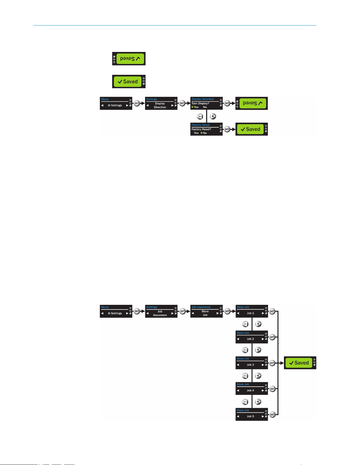
7.8.7 Saving and loading jobs
Stored parameter sets (jobs) make it possible to permanently save and call up specific
application parameters (e.g., taught-in edges, area, sensitivity, etc.) in the device for
certain applications.
The device has 5 memory locations (Job 1 to Job 5).
The available options are
Store Job
•
Saves the active settings on the selected Job 1 to Job 5 memory locations.
Any parameters in this memory location are overwritten.
Load Job
•
Loads the parameter available at the selected memory location.
The active parameters are overwritten.
32
Figure 18: Store Job menu
O PE R AT I NG IN S TR U CT I ON S | AS30 Prime - Edge 8023520/2019-07-15 | SICK
Subject to change without notice
Page 33

Figure 19: Load Job menu
In the Settings menu
1. Select the Job Assurance menu with the +/- pushbutton
2. Open the Job Assurance menu with the SET pushbutton
3. Select the Store Job or Load Job option with the +/- pushbutton
4. Confirm the selection with the SET pushbutton
5. Select the desired job with the +/- pushbutton
6. Confirm the selection with the SET pushbutton
– The display shows SAVED
OPERATION 7
7.9
Additional settings via SOPAS
NOTICE
In this chapter, the operation of the sensor via the SOPAS configuration software is
described.
The SOPAS ET software can be downloaded from the following link:https://
www.sick.com/de/en/sopas-engineering-tool-2018/p/p367244
The driver for this product can be found at www.sick.com/AS30.
7.9.1 Setting up the sensor
The sensor can be set up with the wizard.
The alignment of the sensor (sensing distance, mounting angle) is optimized using the
supplied alignment aid.
8023520/2019-07-15 | SICK O P ER A TI N G I NS T RU C TI O NS | AS30 Prime - Edge
Subject to change without notice
33
Page 34

7 OPERATION
Figure 20: Sensor setup wizard
In SOPAS program
1. Start the wizard with the Sensor setup pushbutton
2. Follow the instructions from the wizard
– Optimize the sensor alignment (sensing distance and mounting bracket).
7.9.2 Selecting the operating mode
The operating mode can be selected in the next step.
The AS30 Prime Edge sensor has 2 possible operating modes:
Edge Detection
•
The edge selected in the Teach-In Edges menu is detected within tolerances val‐
ues. The smoothing function of the sensor, which smooths position values over a
33 ms period, is automatically active. This ensures steady and stable edge guid‐
ing. The time interval for smoothing is configured via IO-Link and SOPAS.
Object Position
•
The edge selected in the Teach-In Edges menu is positioned precisely. The
smoothing function of the sensor is deactivated. Exact reproduction of object posi‐
tioning is now possible.
34
O PE R AT I NG IN S TR U CT I ON S | AS30 Prime - Edge 8023520/2019-07-15 | SICK
Subject to change without notice
Page 35

OPERATION
Figure 21: Operating mode setting
The wizard also asks for the reading direction, the background, the sensitivity, and the
pin assignment configuration.
7
7.9.3 Other sensor settings and diagnostics
The sensor settings can be edited on the “General Device Settings + Diagnostics” tab.
These are:
BackgroundSetting the sensor background between sensing, reflector and auto
•
setting operation see "Selection of reflector / sensing mode", page 30
Reading direction
•
The AS30 Prime Edge offers 2 reading directions for the sensor. The edge position
values are outputted in the configured direction. The analog output on pin 2
switches accordingly. The options are
- From the male connector to the head side (default)
- From the head side to the male connector
- Defined by input pin: Select this option to configure the reading direction via the
input on pin 5.
Pin 2 configuration
•
Pin 2 is the analog output of the detected edge and can be deactivated.
Pin 5 configuration
•
Pin 5 can be configured either as an external input for smart task functions, an
output for edge teach-in, a second digital switching output, an input for running a
reflector teach or an input for changing the reading direction.
Other settings
•
- Activate/Deactivate emitted light
- Set find-me function
- Set IO-Link events
- Set pushbutton lock
8023520/2019-07-15 | SICK O P ER A TI N G I NS T RU C TI O NS | AS30 Prime - Edge
Subject to change without notice
35
Page 36

7 OPERATION
Figure 22: General Device Settings + Diagnostics tab
7.9.4 Enhanced Sensing
The Enhanced Sensing menu enables these functions:
•
•
•
•
Executing edge teach-in
Defining switching points or areas (similar to Area Teach-In)
Configuring field of view
Configuring the analog output
36
O PE R AT I NG IN S TR U CT I ON S | AS30 Prime - Edge 8023520/2019-07-15 | SICK
Subject to change without notice
Page 37

8 Troubleshooting
8.1 Possible errors during commissioning
LED indicator/fault pattern Cause Measures
Yellow Edge display LED
flashing, “Short circuit”
appears in display
“Target missing” appears in
the display while the align‐
ment aid is used
“No edges found” appears
in display
Regular, unwanted teach-in
processes
- Short-circuit / Overcurrent
- Sensor is not connected prop‐
erly
- Distance between the sensor
and the object is too large or too
small
- Light emission (optics) is dirty.
- Adjustment target missing
Programmed contrast or con‐
trast difference is not sufficient
for stable contrast detection.
- Pin 5 configured as input for
Edge Teach, but not activated
TROUBLESHOOTING 8
- Disconnect sensor from the
power network
- Check pin assignment
- Reconnect sensor
- Check the current at the
switching output
- Clean sensor
- Check the application condi‐
tions
- Check adjustment target posi‐
tion.
- Restart adjustment process.
- Clean sensor
- Readjust the sensor
- Check the application condi‐
tions
- Restart teach process
- Increase contrast difference
(sensitivity)
Deactivate pin 5 or connect to
GND
8.2 Possible errors during operation
Table 5: Troubleshooting during operation
Display, error situation Cause Measure
No switching event any more
Field of view does not corre‐
spond to the actual value
An edge is detected even
though there is no object in
the field of view
Distance or angle to mater‐
•
ial not consistent
Sensor dirty
•
Target has changed
•
Sensing distance incorrect
•
Reading direction incorrect
•
Sensor dirty
•
In reflector mode: Reflec‐
•
tor not taught-in
Clean sensor
•
Readjust sensor
•
Check parameter settings
•
Perform teach process
•
again
Realign sensor
Clean sensor
•
Teach in reflector
•
8023520/2019-07-15 | SICK O P ER A TI N G I NS T RU C TI O NS | AS30 Prime - Edge
Subject to change without notice
37
Page 38

9 MAINTENANCE
9 Maintenance
9.1 Maintenance
During operation, the device works maintenance-free.
Depending on the assignment location, the following preventive maintenance tasks
may be required for the device at regular intervals:
Table 6: Maintenance schedule
Maintenance work Interval Implementation
Clean housing and front screen
Check screw connections and plug
connectors
9.2 Cleaning the device
At regular intervals (e.g., weekly), check the light emission window and the housing of
the device for dirt. This is especially relevant in harsh operating environments (dust,
abrasion, damp, fingerprints, etc.). The lens of the light emission window must be kept
clean and dry during operation.
Cleaning interval depends on ambi‐
ent conditions and climate
Every 6 months Specialist
Specialist
NOTICE
Device damage due to improper cleaning!
Improper cleaning may result in device damage.
■
Only use suitable cleaning agents.
■
Never use sharp objects for cleaning.
Cleaning the light emission window
NOTICE
Damage to the light emission window!
Reduced reading performance due to scratches or streaks on the light emission win‐
dow!
Clean the light emission window only when wet.
b
Use a mild cleaning agent that does not contain powder additives. Do not use
b
aggressive cleaning agents, such as acetone, etc.
Avoid any movements that could cause scratches or abrasions on the light emis‐
b
sion window.
Only use cleaning agents suitable for the lens material.
b
NOTE
Static charge may cause dust particles to stick to the light emission window. This effect
can be avoided by using an anti-static glass cleaner in combination with the SICK lens
cloth (can be obtained from www.sick.com).
38
NOTE
If the light emission window is scratched or damaged (cracked or broken), the device
must be replaced. Contact SICK Service to arrange this.
O PE R AT I NG IN S TR U CT I ON S | AS30 Prime - Edge 8023520/2019-07-15 | SICK
Subject to change without notice
Page 39

MAINTENANCE 9
Cleaning the housing
In order to ensure that the heat produced by the internal power loss is adequately dissi‐
pated, the housing surface must be kept clean.
8023520/2019-07-15 | SICK O P ER A TI N G I NS T RU C TI O NS | AS30 Prime - Edge
Subject to change without notice
39
Page 40

10 DECOMMISSIONING
10 Decommissioning
10.1 Disassembly and disposal
Disassembling the device
1. Switch off the supply voltage to the device.
2. Detach all connecting cables from the device.
3. If the device is being replaced, mark its position and alignment on the bracket or
surroundings.
4. Detach the device from the bracket.
Disposing of the device
Any device which can no longer be used must be disposed of in an environmentally
friendly manner in accordance with the applicable country-specific waste disposal regu‐
lations. As it is categorized as electronic waste, the device must never be disposed of
with household waste!
10.2 Returning devices
Do not dispatch devices to the SICK Service department without consultation.
b
NOTE
To enable efficient processing and allow us to determine the cause quickly, please
include the following when making a return:
■
Details of the contact person
■
Description of the application
■
Description of the fault that occurred
40
O PE R AT I NG IN S TR U CT I ON S | AS30 Prime - Edge 8023520/2019-07-15 | SICK
Subject to change without notice
Page 41

11 Technical data
11.1 General data
Table 7: Technical data
Attribute Value
Type designation AS30-
Part number 1095577 1095578
Operating modes Edge guidance (default)
Principle of operation Sensing and reflector Sensing and reflector
Sensing distance 25 mm 100 mm
Working range 20 mm ... 30 mm 90 mm ... 110 mm
Field of view 30 mm 50 mm
Smallest detectable object (MDO) 0.2 mm 0.5 mm
Light source LED, white LED, white
Wavelength 400 nm ... 700 nm 400 nm ... 700 nm
Light spot size 38.9 mm x 11.1 mm 62.5 mm x 13.2 mm
Linearity of position value ±2% ±2%
Repeatability ±0.03 mm ±0.05 mm
Resolution of the display or output
value
Alignment aid Display / IO-Link Display / IO-Link
Teach-in function Edge, Area Edge, Area
Supply voltage 18-30V DC
Ripple ≤5 V
Power consumption < 3.1 W
Switching output Push / pull
Switching output (voltage) Push / Pull: HIGH = VS - 3 V / LOW ≤3 V
Analog output 4 mA ... 20 mA
Analog output resolution 12 bit
Output rate of analog output 1 ms
Output current I
Initialization time 0.48 s
Connection type Male connector, M12, 5-pin
Protection class III
Circuit protection UV connections, reverse polarity protected
Enclosure rating IP67
Weight 250 g
Housing material Zinc die cast, powder-coated
Ambient temperature, operation –10 °C … +55 °C
max.
TECHNICAL DATA 11
AS30EBM314I220A00000C000
ZZ
Object position
1µm 1µm
1
2
< 100 mA
3
Output Q, short-circuit protected and overcurrent pro‐
tected
Electronic interference pulse suppression
EBM534I220A00000C000
ZZZ
Edge guidance (default)
Object position
4
8023520/2019-07-15 | SICK O P ER A TI N G I NS T RU C TI O NS | AS30 Prime - Edge
Subject to change without notice
41
Page 42
31
12,9
1
30
25
16,3
2
3
4
11 TECHNICAL DATA
Attribute Value
Ambient temperature, storage -25 °C … +75 °C
Impact load Acc. to IEC 60068
UL file no. NRKH.E181493 (US)
Communication interface IO-Link V1.1
Communication interface detailed COM3
Cycle time min. 1 ms
Process data length 8 bytes
1
Must not fall below or exceed UB tolerances.
2
Without load
3
Sum current of all outputs
4
Male connector In = 2A
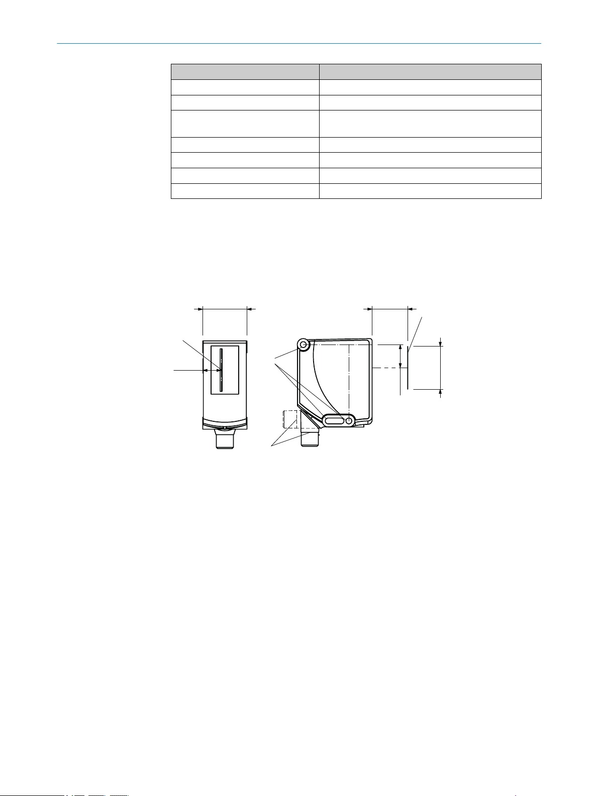
11.2 Dimensional drawing
AS30 Prime Edge TW 25
NRKH7.E181493 (Canada)
Optical axis
1
Field of view, 30 mm
2
Fixing hole, 4.1 mm
3
M12 device connection, can be rotated by 180°
4
42
O PE R AT I NG IN S TR U CT I ON S | AS30 Prime - Edge 8023520/2019-07-15 | SICK
Subject to change without notice
Page 43
AS30 Prime Edge TW 100
31 (1.22)
11.2 (0.44)
1
99.9 (3.93)
45 (1.77)
48.3 (1.9)
52.5 (2.07)
5.5 (0.22)
9 (0.35)
62 (2.44)
32 (1.26)
53.6 (2.11)
4.2 (0.17)
16.3 (0.64)
3
4
2
Optical axis
1
Field of view 50 mm
2
Fixing hole, 4.1 mm
3
M12 device connection, can be rotated by 180°
4
TECHNICAL DATA 11
8023520/2019-07-15 | SICK O P ER A TI N G I NS T RU C TI O NS | AS30 Prime - Edge
Subject to change without notice
43
Page 44

12 ACCESSORIES
12 Accessories
NOTE
Accessories can be found on the online product page at:
b
www.sick.com/AS30
44
O PE R AT I NG IN S TR U CT I ON S | AS30 Prime - Edge 8023520/2019-07-15 | SICK
Subject to change without notice
Page 45

13 Annex
13.1 EU declaration of conformity
The EU declaration of conformity and other certificates can be downloaded from the
Internet at:
www.sick.com/AS30
b
13.2 Certification according to UL60947-5-2
The AS30 Prime series array sensors are certified in accordance with UL60947-5-2 if
they are supplied with power by LPS or Class 2 power supply units.
The certification is only valid with corresponding device identification on the type label
of the respective device.
ANNEX 13
13.3 Licences
SICK uses open-source software. This software is licensed by the rights holders using
the following licenses among others: the free licenses GNU General Public License (GPL
Version2, GPL Version3) and GNU Lesser General Public License (LGPL), the MIT
license, zLib license, and the licenses derived from the BSD license.
This program is provided for general use, but WITHOUT ANY WARRANTY OF ANY KIND.
This warranty disclaimer also extends to the implicit assurance of marketability or suit‐
ability of the program for a particular purpose.
More details can be found in the GNU General Public License. View the complete
license texts here: www.sick.com/licensetexts. Printed copies of the license texts are
also available on request.
SICK uses open-source software. This software is licensed by the rights holders using
the following licenses among others: the free licenses GNU General Public License (GPL
Version2, GPL Version3) and GNU Lesser General Public License (LGPL), the MIT
license, zLib license, and the licenses derived from the BSD license.
This program is provided for general use, but WITHOUT ANY WARRANTY OF ANY KIND.
This warranty disclaimer also extends to the implicit assurance of marketability or suit‐
ability of the program for a particular purpose.
More details can be found in the GNU General Public License. For complete license
texts, see www.sick.com/licensetexts. Printed copies of the license texts are also avail‐
able on request.
8023520/2019-07-15 | SICK O P ER A TI N G I NS T RU C TI O NS | AS30 Prime - Edge
Subject to change without notice
45
Page 46

Detailed addresses and further locations at www.sick.com
Australia
Phone +61 (3) 9457 0600
1800 33 48 02 – tollfree
E-Mail sales@sick.com.au
Austria
Phone +43 (0) 2236 62288-0
E-Mail office@sick.at
Belgium/Luxembourg
Phone +32 (0) 2 466 55 66
E-Mail info@sick.be
Brazil
Phone +55 11 3215-4900
E-Mail comercial@sick.com.br
Canada
Phone +1 905.771.1444
E-Mail cs.canada@sick.com
Czech Republic
Phone +420 234 719 500
E-Mail sick@sick.cz
Chile
Phone +56 (2) 2274 7430
E-Mail chile@sick.com
China
Phone +86 20 2882 3600
E-Mail info.china@sick.net.cn
Denmark
Phone +45 45 82 64 00
E-Mail sick@sick.dk
Finland
Phone +358-9-25 15 800
E-Mail sick@sick.fi
France
Phone +33 1 64 62 35 00
E-Mail info@sick.fr
Germany
Phone +49 (0) 2 11 53 010
E-Mail info@sick.de
Greece
Phone +30 210 6825100
E-Mail office@sick.com.gr
Hong Kong
Phone +852 2153 6300
E-Mail ghk@sick.com.hk
Hungary
Phone +36 1 371 2680
E-Mail ertekesites@sick.hu
India
Phone +91-22-6119 8900
E-Mail info@sick-india.com
Israel
Phone +972 97110 11
E-Mail info@sick-sensors.com
Italy
Phone +39 02 27 43 41
E-Mail info@sick.it
Japan
Phone +81 3 5309 2112
E-Mail support@sick.jp
Malaysia
Phone +603-8080 7425
E-Mail enquiry.my@sick.com
Mexico
Phone +52 (472) 748 9451
E-Mail mexico@sick.com
Netherlands
Phone +31 (0) 30 229 25 44
E-Mail info@sick.nl
New Zealand
Phone +64 9 415 0459
0800 222 278 – tollfree
E-Mail sales@sick.co.nz
Norway
Phone +47 67 81 50 00
E-Mail sick@sick.no
Poland
Phone +48 22 539 41 00
E-Mail info@sick.pl
Romania
Phone +40 356-17 11 20
E-Mail office@sick.ro
Russia
Phone +7 495 283 09 90
E-Mail info@sick.ru
Singapore
Phone +65 6744 3732
E-Mail sales.gsg@sick.com
Slovakia
Phone +421 482 901 201
E-Mail mail@sick-sk.sk
Slovenia
Phone +386 591 78849
E-Mail office@sick.si
South Africa
Phone +27 10 060 0550
E-Mail info@sickautomation.co.za
South Korea
Phone +82 2 786 6321/4
E-Mail infokorea@sick.com
Spain
Phone +34 93 480 31 00
E-Mail info@sick.es
Sweden
Phone +46 10 110 10 00
E-Mail info@sick.se
Switzerland
Phone +41 41 619 29 39
E-Mail contact@sick.ch
Taiwan
Phone +886-2-2375-6288
E-Mail sales@sick.com.tw
Thailand
Phone +66 2 645 0009
E-Mail marcom.th@sick.com
Turkey
Phone +90 (216) 528 50 00
E-Mail info@sick.com.tr
United Arab Emirates
Phone +971 (0) 4 88 65 878
E-Mail contact@sick.ae
United Kingdom
Phone +44 (0)17278 31121
E-Mail info@sick.co.uk
USA
Phone +1 800.325.7425
E-Mail info@sick.com
Vietnam
Phone +65 6744 3732
E-Mail sales
.gsg@sick.com
8023520/2019-07-15/en
SICK AG | Waldkirch | Germany | www.sick.com
 Loading...