

Page 1
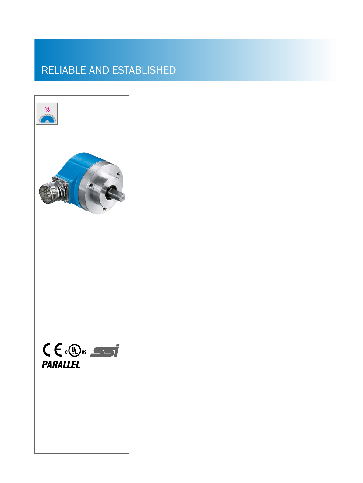
ARS60 SSI/Parallel ABSOLUTE ENCODERS
RELIABLE AND ESTABLISHED
Product description
The modular setup of its CoreTech
technology enables the compact ARS60
absolute singleturn encoder to provide
a customized solution for all applications. All common mechanical variants
At a glance
• Absolute singleturn encoder
• Resolution: up to 15 bit (32,768
steps)
• Electrical interface: SSI with gray or
gray capped code type
• Electrical interface: Parallel with gray,
gray capped, binary, BCD code type
• Zero-set function
are available with any number of steps
between 2 and 32,768 and are either
equipped with an SSI or parallel output,
making the ARS60 a universal solution
for nearly any application requirements
• Mechanical interfaces: face mount
ange, servo ange, blind and through
hollow shaft
• Enclosure rating: Up to IP66
G
More information
Fields of application . . . . . . . . . . .G-455
Detailed technical data. . . . . . . . .G-455
Ordering information. . . . . . . . . . .G-457
Dimensional drawings . . . . . . . . .G-461
PIN assignment. . . . . . . . . . . . . . .G-464
Signal outputs ................G-466
Recommended accessories. . . . .G-468
Your benets
• Programmable resolution (up to
15 bit)
• Simple zero point adjustment directly
on the encoder at the touch of a
button or on a connecting wire (cable
version)
• Suitable for all mounting methods
thanks individual mechanical interfaces
• Application exibility due to easily
interchangeable collets for the blind
hollow shaft and through hollow shaft
G-454
ENCODERS | SICK 8015560/2015-09-01
Subject to change without notice
Page 2

Fields of application
• Electronics and solar industry
• Textile machinery
• Packaging industry
• High-bay warehouses
Detailed technical data
Performance
ABSOLUTE ENCODERS ARS60 SSI/Parallel
• Woodworking machines
• Mechanical engineering
• Automotive industry
• Material handling
Number of steps per revolution
Max. number of revolutions
00002 ... 32,768 (see ordering information)
1
Error limits
Binary number of steps 0.035°
Non-binary number of steps 0.046°
Repeatability
0.005°
Measurement step deviation
Binary number of steps 0.005°
Non-binary number of steps 0.016°
Measurement step
Initialization time
1)
Valid positional data can be read once this time has elapsed.
360° / Number of lines per revolution
1)
80 ms
Electrical data
Electrical interface
Control input switching level
Operation of SET button
1)
Operating voltage range
Operating current
Parallel Typ. 90 mA
Code sequence
Reverse polarity protection
MTTFd: mean time to dangerous failure
1)
This product is a standard product and does not constitute a safety component as dened in the Machinery Directive. Calculation based on nominal load of devices,
average ambient temperature 40 °C, frequency of use 8,760 h/a. All electronic failures are considered hazardous. For more information, see document no.
8015532.
SSI or parallel
Logic H = 0.7 x U
Logic L = 0 V… 0.3 V x U
100 ms
10 V DC ... 32 V DC
SSI Typ. 60 mA
CW, increasing, when viewing the clockwise rotating shaft
l
300 years (EN ISO 13849-1)
S
S
1)
G
Subject to change without notice
ENCODERS | SICK8015560/2015-09-01
G-455
Page 3

G
ARS60 SSI/Parallel ABSOLUTE ENCODERS
Mechanical data
Shaft diameter
Face mount ange 10 x 19 mm
Servo ange 6 x 10 mm
1)
Blind hollow shaft
Through hollow shaft
Shaft material
Flange material
Housing material
2)
Mass
Start up torque at 20 °C
Face mount ange 0.4 Ncm
Servo ange 0.25 Ncm
Blind hollow shaft 0.6 Ncm
Through hollow shaft 2.2 Ncm
Operating torque at 20 °C
Face mount ange 0.3 Ncm
Servo ange 0.2 Ncm
Blind hollow shaft 0.4 Ncm
Through hollow shaft 1.6 Ncm
Permissible shaft loading
Face mount ange, servo ange 10 N radial
Permissible shaft movement of the drive
element, static/dynamic
Blind hollow shaft, through hollow shaft ± 0.3/ ± 0.1 mm radial
Max. angular acceleration
Operating speed
Blind hollow shaft, through hollow shaft 3,000 rpm
3)
Face mount ange, servo ange 6,000 rpm with shaft seal
Rotor moment of inertia
Face mount ange 54 gcm²
Servo ange 48 gcm²
Blind hollow shaft, through hollow shaft See Figure 1 below.
Bearing lifetime
1)
Order collets for 6, 8, 10, 12 and 14 mm or 1/4", 3/8" and 1/2" as separate extra accessories. No collets are necessary for 15 mm shaft diameter.
2)
Relates to devices with cable outlet.
3)
Take into account self-warming of 3.3 K per 1,000 rpm when designing operating temperature range
6, 8, 10, 12, 14, 15 mm and 1/4", 3/8", 1/2"
1)
6, 8, 10, 12 mm and 1/4", 3/8", 1/2"
Stainless steel
Aluminum
Aluminum
0.3 kg
50 N axial
± 0.5/ ± 0.2 mm axial
≤ 500,000 rad/s²
10,000 rpm without shaft seal, if the shaft seal has been removed by the customer
3,6 x 10⁹ revolutions
G-456
ENCODERS | SICK 8015560/2015-09-01
Subject to change without notice
Page 4
Ambient data
EMC
Enclosure rating (as per IEC 60529)
Face mount ange, servo ange, blind hollow
shaft: male connector outlet
Face mount ange, servo ange, blind hollow
shaft: cable outlet
Through hollow shaft: male connector outlet IP 64
Through hollow shaft: cable outlet IP 64
2)
Permissible relative humidity
Operating temperature range
Storage temperature range
Resistance to shocks
Resistance to vibrations
1)
The EMC according to the standards quoted is achieved if shielded cables are used.
2)
When mating connector is inserted.
(according to EN 61000-6–2 and EN 61000-6-3)
IP 65
IP 66
90% (condensation of optical surfaces not permitted)
–20 °C ... +85 °C
–40 °C ... +100 °C
50 g/ 11 ms (as per EN 60068-2-27)
20 g / 10 Hz - 2,000 Hz (according to EN 60068-2-6)
Ordering information
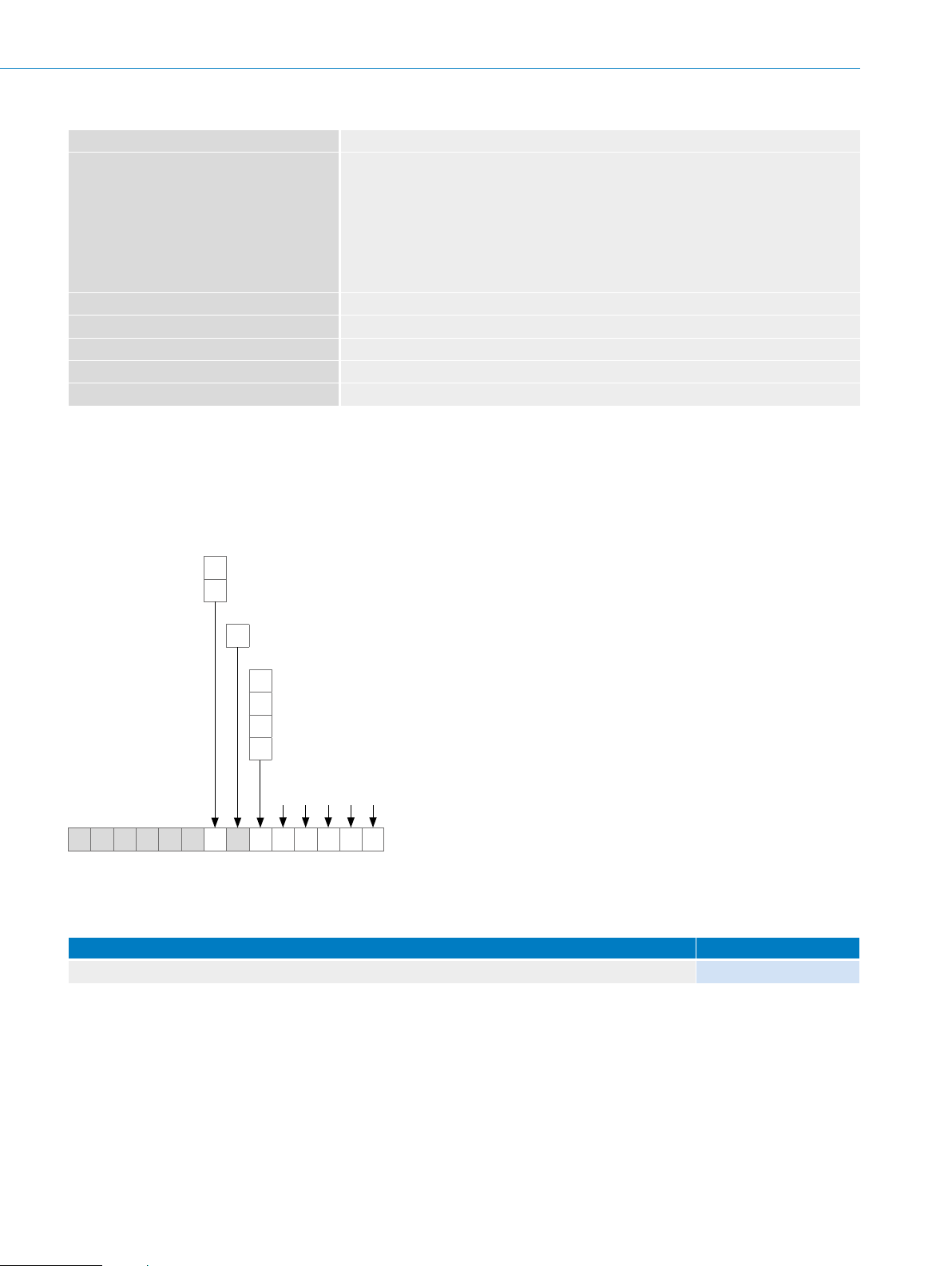
Type code: ARS60 SSI, through hollow shaft
ABSOLUTE ENCODERS ARS60 SSI/Parallel
1)
Electrical interface
10 … 32 V, SSI/Gray
A
10 … 32 V, SSI/Gray, capped
B
Mechanical design
Through hollow shaft
D
1)
Connection type
Male connector M23, 12-pin, radial outlet
A
Cable, 11-wire, radial outlet, 1.5 m
K
Cable, 11-wire, radial outlet, 3.0 m
L
Cable, 11-wire, radial outlet, 5.0 m
M
Resolution
Any number of steps from 00002 to 32768 possible. Always 5 characters in clear text.
A R S 6 0 – D
1)
Order collet for 6, 8, 10 and 12 mm or 1/4", 3/8" and 1/2" as separate extra accessories (see recommended accessories).
Example orders
• Through hollow shaft
Through hollow shaft design Type
10 ... 32 Volt, SSI, Gray, M23 male connector, 12-pin, radial, number of steps 8,192 ARS60-ADA08192
G
Subject to change without notice
ENCODERS | SICK8015560/2015-09-01
G-457
Page 5
ARS60 SSI/Parallel ABSOLUTE ENCODERS
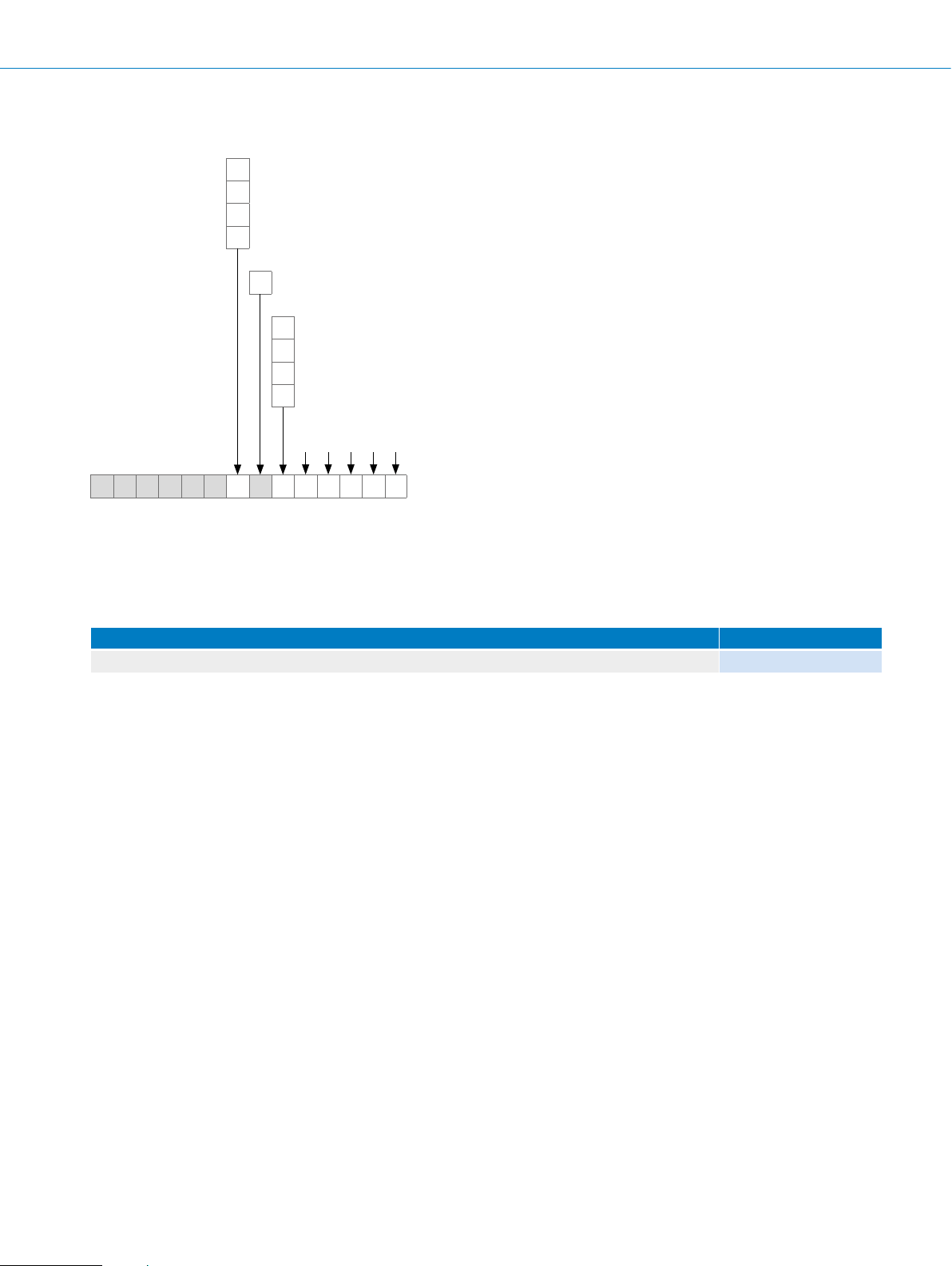
Type code: ARS60 parallel, through hollow shaft
Electrical interface
10 … 32 V, Parallel, Gray
F
10 … 32 V, Parallel, Gray, capped
G
10 … 32 V, Parallel, BIN
H
10 … 32 V, Parallel, BCD
J
Mechanical design
Through hollow shaft
D
Connection type
Male connector, M23, 21-pin, radial outlet
A
Cable, 22-wire, radial outlet, 1.5 m
K
Cable, 22-wire, radial outlet, 3.0 m
L
Cable, 22-wire, radial outlet, 5.0 m
M
Resolution
Any number of steps from 00002 to 32768 possible. Always 5 characters in clear text.
A R S 6 0 – D
1)
Order collet for 6, 8, 10 and 12 mm or 1/4", 3/8" and 1/2" as separate extra accessories (see recommended accessories).
2)
For the following interfaces: 10 … 32 V Parallel Gray; 10 … 32 V Parallel Gray capped; 10 … 32 V Parallel BIN.
00002 to 07999 steps possible for the electrical interface: 10 ... 32 V, Parallel BCD. Always 5 characters in clear text.
1)
2)
G
Example orders
• Through hollow shaft
Through hollow shaft design Type
10 ... 32 Volt, Parallel, Gray, M23 male connector, 21-pin, radial, number of steps 8,192 ARS60-FDA08192
G-458
ENCODERS | SICK 8015560/2015-09-01
Subject to change without notice
Page 6

Type code: ARS60 SSI
Electrical interface
A
B
ABSOLUTE ENCODERS ARS60 SSI/Parallel
10 … 32 V, SSI/Gray
10 … 32 V, SSI/Gray, capped
Mechanical design
Solid shaft, face mount ange, Ø 10 mm, length 19 mm
4
Solid shaft, servo ange, Ø 6 mm, length 10 mm
1
Blind hollow shaft
A
Connection type
Male connector M23, 12-pin, radial outlet
A
M23 male connector, 12-pin, axial outlet
B
Cable, 11-wire, radial outlet, 1.5 m
K
Cable, 11-wire, radial outlet, 3.0 m
L
Cable, 11-wire, radial outlet, 5.0 m
M
Cable, 11-wire, axial outlet, 1.5 m
R
Cable, 11-wire, axial outlet, 3.0 m
S
Cable, 11-wire, axial outlet, 5.0 m
T
Resolution
Any number of steps from 00002 to 32768 possible. Always 5 characters in clear text.
1)
A R S 6 0 –
1)
Order collet for 6, 8, 10, 12 and 14 mm or 1/4", 3/8" and 1/2" as separate extra accessories (see recommended accessories). No collets are neces-
sary for 15 mm shaft diameter.
Example orders
• Face mount ange
Face mount ange design Type
10 ... 32 Volt, SSI, Gray, M23 male connector, 12-pin, radial, number of steps 8,192 ARS60-A4A08192
• Servo ange
Servo ange design Type
10 ... 32 Volt, SSI, Gray, M23 male connector, 12-pin, radial, number of steps 8,192 ARS60-A1A08192
• Blind hollow shaft
Blind hollow shaft design Type
10 ... 32 Volt, SSI, Gray, M23 male connector, 12-pin, radial, number of steps 8,192 ARS60-AAA08192
G
Subject to change without notice
ENCODERS | SICK8015560/2015-09-01
G-459
Page 7

ARS60 SSI/Parallel ABSOLUTE ENCODERS
Type code: ARS60 parallel
Electrical interface
10 … 32 V, Parallel, Gray
F
10 … 32 V, Parallel, Gray, capped
G
10 … 32 V, Parallel, BIN
H
10 … 32 V, Parallel, BCD
J
Mechanical design
Solid shaft, face mount ange, Ø 10 mm, length 19 mm
4
Solid shaft, servo ange, Ø 6 mm, length 10 mm
1
Blind hollow shaft
A
Connection type
Male connector, M23, 21-pin, radial outlet
A
Male connector, M23, 21-pin, axial outlet
B
Cable, 22-wire, radial outlet, 1.5 m
K
Cable, 22-wire, radial outlet, 3.0 m
L
Cable, 22-wire, radial outlet, 5.0 m
M
Cable, 22-wire, axial outlet, 1.5 m
R
Cable, 22-wire, axial outlet, 3.0 m
S
Cable, 22-wire, axial outlet, 5.0 m
T
Resolution
Any number of steps from 00002 to 32768 possible. Always 5 characters in clear text.
1)
2)
G
A R S 6 0 –
1)
Order collet for 6, 8, 10, 12 and 14 mm or 1/4", 3/8" and 1/2" as separate extra accessories (see recommended accessories). No collets are neces-
sary for 15 mm shaft diameter.
2)
For the following interfaces: 10 … 32 V Parallel Gray; 10 … 32 V Parallel Gray capped; 10 … 32 V Parallel BIN.
00002 to 07999 steps possible for the electrical interface: 10 ... 32 V, Parallel BCD. Always 5 characters in clear text.
Example orders
• Servo ange
Servo ange design Type
10 ... 32 Volt, Parallel, Gray, M23 male connector, 21-pin, radial, number of steps 8,192 ARS60-F1A08192
• Face mount ange
Face mount ange design Type
10 ... 32 Volt, Parallel, Gray, M23 male connector, 21-pin, radial, number of steps 8,192 ARS60-F4A08192
• Blind hollow shaft
Blind hollow shaft design Type
10 ... 32 Volt, Parallel, Gray, M23 male connector, 21-pin, radial, number of steps 8,192 ARS60-FAA08192
G-460
ENCODERS | SICK 8015560/2015-09-01
Subject to change without notice
Page 8

Dimensional drawings (dimensions in mm)
Ø 42
M4 8 deep
0.1
A
Servo ange, radial
±0.1
M4 8 deep
(0.31)
Ø 0.2
B
(1.65)
ABSOLUTE ENCODERS ARS60 SSI/Parallel
0.1
Ø 0.2
A
+0.5
54
(2.13)
A
4.5
(0.18)
120°
25°
24
(2.60)
66
(0.94)
20
10
(0.39)
(0.79)
R
Ø 60 (2.36)
General tolerances according to ISO 2768-mk
1 R = min. bend radius 40 mm
Servo ange, axial
(0.31)
120°
Ø 0.2
B
4.5
(0.18)
1
±0.1
Ø 42
(1.65)
20
(0.79)
R
25°
Ø 60 (2.36)
1
Ø 8
(0.31)
(2.34)
±0.1
Ø 59.5
Ø 8
(0.31)
(2.34)
±0.1
Ø 59.5
+0.1
Ø 58 (2.28)
(2.28)
Ø 58
Ø 0.2
(2.03)
Ø 51.5
0.2
(2.03)
+0.1
Ø 51.5
Ø 50 f8 (1.97)
B
10
(0.39)
Ø 50 f8 (1.97)
B
0.2
A
A
(0.24)
Ø 6 f6
A
±1
(0.16)
(0.12)
Ø 6 f6
10
(0.39)
4
3
3
(0.12)
A
(0.24)
A
±1
(0.16)
(0.12)
4
3
3
(0.12)
61
±0.5
(2.40)
24
(0.94)
4.5
(0.18)
24
13.5
(0.53)
66 (2.60)
(0.94)
(3.54)
90
G
General tolerances according to ISO 2768-mk
1 R = min. bend radius 40 mm
Subject to change without notice
ENCODERS | SICK8015560/2015-09-01
G-461
Page 9

ARS60 SSI/Parallel ABSOLUTE ENCODERS
4.5
10
Ø 48
10
4.5
Face mount ange, radial
±0.1
M4 8
(0.31) deep
Ø 0.2
B
(1.89)
120°
0.1
Ø 0.2
A
±0.5
45
(0.39)
A
A
B
(1.77)
(0.18)
G
24
66 (2.60)
(0.94)
20
10
(0.39)
(0.79)
28°
Ø 60 (2.36)
General tolerances according to ISO 2768-mk
1 R = min. bend radius 40 mm
±0.1
Ø 48
M4 8
(0.31) deep
Ø 0.2
B
(1.89)
28°
Ø 60 (2.36)
120°
4.5
(0.18)
20
24
13.5
(0.53)
66 (2.60)
(0.94)
(3.54)
90
Ø 59.5 (2.34)
Ø 36 f8 (1.42)
R
1
Ø 8
(0.31)
0.1
Ø 0.2
(0.39)
Ø 10 f7
A
A
9
(0.35)
(0.39)
0.2
B
18
(0.71)
19
(0.75)
A
±1
±0.5
52
(2.05)
A
(2.36)
60
4.5
24
Ø 10 f7
(0.31)
(0.39)
9
(0.35)
0.2
18
(0.71)
19
(0.75)
A
(0.18)
±1
(0.94)
Ø 59.5 (2.34)
Ø 36 f8 (1.42)
1
R
Ø 8
Blind hollow shaft, axial
72 (2.83)
Ø 63 (2.48)
Ø 3.2
(0.13)
20
(0.79)
+0.1
20°
4.5
(0.18)
Ø 60 (2.36)
20
(0.79)
General tolerances according to ISO 2768-mk
1 R = min. bend radius 40 mm
G-462
ENCODERS | SICK 8015560/2015-09-01
R
1
Ø 32–0.5
(0.14)
(0.08)
(1.26)
Ø XF7
Ø 8
3.6
2
(0.31)
68.7 (2.70)
(0.18)
4.5
(0.18)
24
(0.94)
(2.36)
60
Subject to change without notice
Page 10

ABSOLUTE ENCODERS ARS60 SSI/Parallel
4.5
4.5
72 (2.83)
Ø 63 (2.48)
20
(0.79)
+0.1
Ø 3.2
(0.13)
Ø 60 (2.36)
Through hollow shaft, radial
72 (2.83)
Ø 63 (2.48)
20
(0.79)
+0.1
Ø 3.2
(0.13)
Ø 60 (2.36)
20°
20°
(0.18)
20
(0.79)
(2.60)
66
20
4.5
10
(0.39)
(0.79)
1
Ø 32–0.5
(0.14)
(0.08)
(1.26)
Ø XF7
3.6
68.7 (2.70)
2
(0.18)
4.5
(0.18)
24
(0.94)
60 (2.36)
R
Ø 8
(0.31)
+0.5
66.7
(2.63)
(0.18)
2
(1.16)
Ø XF7
Ø 29.5
2
(0.08)
3.6
(0.14)
R
1
Ø 8
(0.31)
13.5
(0.53)
24
(0.94)
General tolerances according to ISO 2768-mk
1 R = min. bend radius 40 mm
2 Min. shaft insertion depth 15 mm
G
Subject to change without notice
ENCODERS | SICK8015560/2015-09-01
G-463
Page 11

ARS60 SSI/Parallel ABSOLUTE ENCODERS
PIN assignment
Pin assignment for design with 12-pin male connector; SSI interface
Signal 12-pin male device connector 11-wire cable outlet
GND 1 Blue
Data (+) 2 White
Clock (+) 3 Yellow
N. C. 4 –
V/¯R 5 Pink
N. C. 6 –
N. C. 7 –
8 Red
U
S
SET 9 Orange
Data (–) 10 Brown
Clock (–) 11 Violet
N. C. 12 –
G
9
2
1
101112
3
8
7
6
45
View of 12-pin M23 device connector on SSI encoder
G-464
ENCODERS | SICK 8015560/2015-09-01
Subject to change without notice
Page 12

ABSOLUTE ENCODERS ARS60 SSI/Parallel
Pin assignment for design with 21-pin male connector, single; parallel interface
Wire colors at cable
PIN
1 Violet 2
2 White/brown 2
3 White/green 2
4 White/yellow 2
5 White/gray 2
6 White/pink 2
7 White/blue 2
8 White/red 2
9 White/black 2
10 Brown/green 2
11 Brown/yellow 2
12 Brown/gray 2
13 Brown/pink 2
14 Brown/blue 2
15 Brown/red 2
16 Green Parity Parity Parity
17 Pink Store_ Store_ Store_
18 Yellow Enable_ Enable_ Enable_
19 Brown V/R_ V/R_ V/R_
1) Gray SET SET SET
20 Blue GND GND GND
21 Red U
Housing Screen Screen Screen
1)
Set cable only possible at cable outlet.
U
Encoder’s supply voltage (always observe the encoder’s type label prior to commissioning).
S
GND Encoder ground connection; electrically isolated from the housing. The voltage relating to GND is U
V/R_ Forwards/Reverse: This input programs the counting direction for the encoder. When it is not connected, this input is set to HIGH. If the encoder shaft is
Enable_ This input activates the data output driver if a LOW level is connected. When it is not connected, this input is set to LOW. The outputs are in tri-state mode
Store_ This input stores the encoder data in gray code when connecting a LOW level. This helps to prevent read errors if the output data is requested in binary
Parity This output supplies a HIGH level when the checksum is even.
SET This input is for electronic zeroing. If the SET cable is set to U
rotated clockwise (to the right) as viewed when facing the drive shaft, it counts in ascending order. If it should count in ascending order when the shaft is
rotated counterclockwise (to the left), then this connection must be permanently set to LOW level (GND).
when the level is HIGH.
code. If this input is set to LOW, the data at the encoder output is stable, regardless of whether the input shaft is rotating. When it is not connected, this
input is set to HIGH.
outlet Binary Gray BCD Explanation
0
1
2
3
4
5
6
7
8
9
10
11
12
13
14
S
for more than 100 ms, the mechanical position corresponds to the value 0.
S
G
0
G
1
G
2
G
3
G
4
G
5
G
6
G
7
G
8
G
9
G
10
G
11
G
12
G
13
G
14
U
S
S
20 v.10
21 v.10
22 v.10
23 v.10
20 v.10
21 v.10
22 v.10
23 v.10
20 v.10
21 v.10
22 v.10
23 v.10
20 v.10
21 v.10
22 v.10
U
.
0
0
0
0
1
1
1
1
2
2
2
2
3
3
3
S
Data cables
Outputs
G
1
11
10
13
20
21
15
4
5
View of 21-pin M23 device connector on parallel encoder
Subject to change without notice
ENCODERS | SICK8015560/2015-09-01
G-465
Page 13

ARS60 SSI/Parallel ABSOLUTE ENCODERS
Signal outputs
SSI data format for resolutions ≤ 8,192 (1–13 bit)
In order to ensure compatibility with the data formats available on the market, the ARS60 distinguishes between two data formats:
The rst data format is for encoders with resolutions up to 13 bit.
This is the standard data format for the singleturn absolute encoder.
G
SSI data format for resolutions > 8,192 (14 and 15 bit)
All data is transmitted MSB-justied. Two errorbits follow the 15 data bits.
Error 1 (E1) = Position error
An error has occurred during the position detection process since the last SSI transmission. This errorbit is deleted during the next
SSI transmission.
Error 2 (E2) = Sender monitoring
Parallel interface (output driver 7272 push pull)
• Tri-state-compatible
• Short-circuit protected
• Reverse polarity protection
• Integrated transient protection diodes
G-466
ENCODERS | SICK 8015560/2015-09-01
Subject to change without notice
Page 14

Technical data for parallel interface
ABSOLUTE ENCODERS ARS60 SSI/Parallel
IdH max. at +85 C ,8 nF load 6,000 rpm
IdL max. at +85 C ,8 nF load 6,000 rpm
Output saturation level (H level)
At IdH10 mA
-UdH30 mA
U
S
Output saturation level (L level)
At IdL10 mA
Ud
Position repeatability (depending on encoder resolution and output code)
Parallel gray code 60 µs
Parallel BIN code 60 µs
Parallel BCD code 200 µs
L
30 mA
30 mA
2.8 V
3.0 V
0.4 V
30 mA
2.0 V
G
Subject to change without notice
ENCODERS | SICK8015560/2015-09-01
G-467
Page 15

ARS60 SSI/Parallel ABSOLUTE ENCODERS
Recommended accessories
Mounting systems
Mounting brackets and plates
Mounting bracket
Figure Brief description Type Part no.
G
Mounting bracket for encoder with centering hub 36 mm, including mounting kit for face
mount ange
Dimensional drawings g page K-725
BEF-WF-36 2029164
Flanges
Flange plate
Figure Brief description Type Part no.
Flange adapter, adaptation of face mount ange with 36 mm centering hub to 50 mm
servo ange, aluminum, including 3 at head screws M4 x 10
Flange adapter, adaptation of face mount ange with 36 mm centering hub to 60 mm
square mounting plate, aluminum, including 3 at head screws M4 x 10
Flange adapter, adaptation of face mount ange with 36 mm centering hub to 58 mm
square mounting plate with shock absorbers, aluminum
Flange adapter, adaptation of face mount ange with 36 mm centering hub to 63 mm
square mounting plate, aluminum, including 3 at head screws M4 x 10
Flange adapter, adaptation of face mount ange with 36 mm centering hub to 100 mm
servo ange with 60 mm centering hub, aluminum
Dimensional drawings g page K-725
BEF-FA-036-050 2029160
BEF-FA-036-060REC 2029162
BEF-FA-036-060RSA 2029163
BEF-FA-036-063REC 2034225
BEF-FA-036-100 2029161
Other mounting accessories
Measuring wheels and measuring wheel systems
Figure Brief description Type Part no.
Measuring wheel with smooth plastic surface (Hytrel) for 10 mm solid shaft, circumference 200 mm
Measuring wheel with ridged plastic surface (Hytrel) for 10 mm solid shaft, circumference 200 mm
Measuring wheel with smooth plastic surface (Hytrel) for 10 mm solid shaft, circumference 500 mm
Measuring wheel with O-ring (NBR70) for 6 mm solid shaft, circumference 200 mm BEF-MR006020R 2055222
Measuring wheel with O-ring (NBR70) for 6 mm solid shaft, circumference 300 mm BEF-MR006030R 2055634
Measuring wheel with O-ring (NBR70) for 10 mm solid shaft, circumference 300 mm BEF-MR010030R 2049278
Dimensional drawings g page K-725
G-468
ENCODERS | SICK 8015560/2015-09-01
BEF-MR-010020 5312988
BEF-MR-010020G 5318678
BEF-MR-010050 5312989
Subject to change without notice
Page 16

ABSOLUTE ENCODERS ARS60 SSI/Parallel
Mounting bell
Figure Brief description Type Part no.
Mounting bell for encoders with a servo ange, centering hub 50 mm, including mounting kit
Dimensional drawings g page K-725
BEF-MG-50 5312987
Servo clamps
Figure Brief description Type Part no.
Half-shell servo clamps (2 pcs.) for servo anges with a 50 mm centering hub BEF-WG-SF050 2029165
Servo clamps, large, for servo anges (clamps, eccentric fastener), 3 pcs., without
mounting material
Dimensional drawings g page K-725
BEF-WK-SF 2029166
Miscellaneous
Figure Brief description Type Part no.
Mounting kit for servo ange encoder on the bearing block, 1 bar coupling SKPS
1520 06/06 1 hexagon socket wrench SW1.5 DIN 911, 3 mounting eccentric BEMN
1242 49 3 screws M4 x 10 DIN 912, 1 hexagon socket wrench SW3 DIN 911
Bearing block for hollow shaft encoder, including xing screws BEF-FA-B12-010 2042728
BEF-MK-LB 5320872
Bearing block for servo and face mount ange encoder BEF-FA-LB1210 2044591
G
Subject to change without notice
ENCODERS | SICK8015560/2015-09-01
G-469
Page 17

G
ARS60 SSI/Parallel ABSOLUTE ENCODERS
Shaft couplings
Figure Brief description Type Part no.
Bellows coupling, shaft diameter 6 mm / 6 mm, maximum shaft offset: radial
± 0.25 mm, axial ± 0.4 mm, angular ± 4°; max. speed 10,000 rpm, -30° to +120 °C,
max. torque 80 Ncm; material: stainless steel bellows, aluminum hub
Bellows coupling, shaft diameter 6 mm / 10 mm, maximum shaft offset: radial
± 0.25 mm, axial ± 0.4 mm, angular ± 4°; max. speed 10,000 rpm, -30° to +120 °C,
max. torque 80 Ncm; material: stainless steel bellows, aluminum hub
Bellows coupling, shaft diameter 10 mm/10 mm; maximum shaft offset: radial
± 0.25 mm, axial ± 0.4 mm, angular ± 4°; max. revolutions 10,000 rpm, -30° to
+120 °C, max. torque 80 Ncm; material: stainless steel bellows, aluminum clamping
hubs
Bellows coupling, shaft diameter 10 mm/12 mm; maximum shaft offset: radial
± 0.25 mm, axial ± 0.4 mm, angular ± 4°; max. revolutions 10,000 rpm, -30° to
+120 °C, max. torque 80 Ncm; material: stainless steel bellows, aluminum clamping
hubs
Bar coupling, shaft diameter 6 mm / 6 mm, maximum shaft offset: radial ± 0.3 mm,
axial ± 0.2 mm, angle ± 3°; max. speed 10,000 rpm, -10° to +80 °C, max. torque
80 Ncm; material: ber-glass reinforced polyamide, aluminum hub
Bar coupling, shaft diameter 6 mm / 8 mm, maximum shaft offset radial ± 0.3 mm, ax-
ial ± 0.2 mm, angle ± 3°, max. speed 10,000 rpm, torsion spring rigidity 38 Nm/wheel;
material: ber-glass reinforced polyamide, aluminum hub
Bar coupling, shaft diameter 6 mm/10 mm, maximum shaft offset: radial ± 0.3 mm,
axial ± 0.2 mm, angular ± 3°; max. speed 10,000 rpm, -10° to +80 °C, max. torque
80 Ncm; material: ber-glass reinforced polyamide, aluminum hub
Bar coupling, shaft diameter 8 mm / 10 mm, maximum shaft offset: radial ± 0.3 mm,
axial ± 0.2 mm, angular ± 3°; torsion spring rigidity 38 Nm/wheel; material: ber-glass
reinforced polyamide, aluminum hub
Bar coupling, shaft diameter 10 mm / 10 mm, maximum shaft offset radial ± 0.3 mm,
axial ± 0.2 mm, angle ± 3°; max. speed 10,000 rpm, torsion spring rigidity 38 Nm/
wheel; material: ber-glass reinforced polyamide, aluminum hub
Double-loop coupling, shaft diameter 6 mm/10 mm, maximum shaft offset: radial
± 2.5 mm, axial ± 3 mm, angular ± 10°; max. speed 3,000 rpm, -30° to +80 °C, max.
torque 1.5 Nm; material: polyurethane, galvanized steel ange
Double-loop coupling, shaft diameter 8 mm/10 mm, maximum shaft offset: radial
± 2.5 mm, axial ± 3 mm, angular ± 10°; max. speed 3,000 rpm, -30° to +80 °C, max.
torque 1.5 Nm; material: polyurethane, galvanized steel ange
Double-loop coupling, shaft diameter 10 mm/10 mm, maximum shaft offset: radial
± 2.5 mm, axial ± 3 mm, angular ± 10°; max. speed 3,000 rpm, -30° to +80 °C, max.
torque 1.5 Nm; material: polyurethane, galvanized steel ange
Double-loop coupling, shaft diameter 10 mm/12 mm, maximum shaft offset: radial
± 2.5 mm, axial ± 3 mm, angular ± 10°; max. speed 3,000 rpm, -30° to +80 °C, max.
torque 1.5 Nm; material: polyurethane, galvanized steel ange
Spring washer coupling, shaft diameter 6 mm/10 mm, maximum shaft offset: radial
± 0.3 mm, axial ± 0.4 mm, angular ± 2.5°; max. speed 12,000 rpm, -10° to +80 °C,
max. torque 60 Ncm; material: aluminum ange, ber-glass reinforced polyamide mem-
brane and tempered steel coupling pin
Spring washer coupling, shaft diameter 10 mm / 10 mm, maximum shaft offset: radial
± 0.3 mm, axial ± 0.4 mm, angular ± 2.5°; max. speed 12,000 rpm, –10° to +80 °C,
max. torque 60 Ncm; material: aluminum ange, glass ber-reinforced polyamide mem-
brane and hardened steel coupling pin
KUP-0606-B 5312981
KUP-0610-B 5312982
KUP-1010-B 5312983
KUP-1012-B 5312984
KUP-0606-S 2056406
KUP-0608-S 5314179
KUP-0610-S 2056407
KUP-0810-S 5314178
KUP-1010-S 2056408
KUP-0610-D 5326697
KUP-0810-D 5326704
KUP-1010-D 5326703
KUP-1012-D 5326702
KUP-0610-F 5312985
KUP-1010-F 5312986
Dimensional drawings g page K-725
G-470
ENCODERS | SICK 8015560/2015-09-01
Subject to change without notice
Page 18

Connectivity
Plug connectors and cables
Connecting cables with female connector
ABSOLUTE ENCODERS ARS60 SSI/Parallel
Figure Brief description Length
Type Part no.
of
cable
1.5 m DOL-2312-G1M5MA2 2029206
Head A: female connector, M23, 12-pin, straight
Head B: cable
Cable: suitable for drag chain, PUR, shielded, 4 x 2 x 0.25 mm² + 2 x 0.5 mm²
+ 2 x 0.14 mm², Ø 7.8 mm
Head A: female connector, M23, 21-pin, straight
Head B: cable
Cable: PUR, halogen-free, shielded, 20 x 0.14 mm², 2 x 0.25 mm², Ø 7.8 mm
1)
For ARS60 SSI.
2)
For ARS60 Parallel.
Dimensional drawings g page K-725
1)
3 m DOL-2312-G03MMA2 2029207
5 m DOL-2312-G05MMA2 2029208
10 m DOL-2312-G10MMA2 2029209
20 m DOL-2312-G20MMA2 2029210
30 m DOL-2312-G30MMA2 2029211
1.5 m DOL-2321-G1M5PA4 2029218
3 m DOL-2321-G03MPA4 2029219
5 m DOL-2321-G05MPA4 2029220
2)
10 m DOL-2321-G10MPA4 2029221
20 m DOL-2321-G20MPA4 2029222
Female connectors (ready to assemble)
Figure Brief description Type Part no.
Head A: female connector, M23, 12-pin, straight, shielded, for cable diameter 5.5 mm ...
10.5 mm
Head B: -
Operating temperature: –20 °C ... +130 °C
Head A: female connector, M23, 12-pin, straight, shielded, for cable diameter 5.5 mm ...
10.5 mm
Head B: Operating temperature:
–40 °C ... +125 °C
Head A: female connector, M23, 12-pin, angled, shielded, for cable diameter 4.2 mm ...
6.6 mm
Head B: -
Operating temperature: –20 °C ... +130 °C
Head A: female connector, M23, 21-pin, straight, shielded, for cable diameter 5.5 mm ...
12 mm
Head B: -
Head A: female connector, D-Sub, 37-pin, straight, shielded
Head B: -
DOS-2312-G 6027538
DOS-2312-G02
DOS-2312-W01 2072580
DOS-2321-G 6027539
DOS-0D37-G 2029224
2077057
G
Dimensional drawings g page K-725
Subject to change without notice
ENCODERS | SICK8015560/2015-09-01
G-471
Page 19

ARS60 SSI/Parallel ABSOLUTE ENCODERS
Cables (ready to assemble)
Figure Brief description Length
Type Part no.
of
cable
Head A: cable
Head B: cable
Cable: suitable for drag chain, PUR, halogen-free, shielded, 4 x 2 x 0.15 mm²,
Ø 5.6 mm
Head A: cable
Head B: cable
Cable: PUR, shielded, 4 x 2 x 0.25 mm² + 2 x 0.5 mm² + 1 x 0.14 mm²,
Ø 7.5 mm
Head A: cable
Head B: cable
Cable: suitable for drag chain, PUR, halogen-free, shielded, 4 x 2 x 0.25 mm² +
2 x 0.5 mm² + 2 x 0.14 mm², Ø 7.8 mm
Head A: cable
Head B: cable
Cable: suitable for drag chain, PUR, halogen-free, shielded, UV and saltwater-resistant, 4 x 2 x 0.25 mm² + 2 x 0.5 mm² + 2 x 0.14 mm², Ø 7.8 mm
Head A: cable
Head B: cable
Cable: PUR, halogen-free, shielded, 20 x 0.14 mm², 2 x 0.25 mm², Ø 7.8 mm
By the
meter
By the
meter
By the
meter
By the
meter
By the
meter
LTG-2308-MWENC 6027529
LTG-2411-MW 6027530
LTG-2512-MW 6027531
LTG-2612-MW 6028516
LTG-2622-MW 6027532
Male connectors (ready to assemble)
Figure Brief description Type Part no.
Head A: male connector, D-Sub, 15-pin, straight, shielded
Head B: -
STE-0D15-G 2029223
G
Head A: male connector, M23, 12-pin, straight, shielded, for cable diameter 5.5 mm ...
10.5 mm
Head B: -
Operating temperature: –20 °C ... +130 °C
Head A: male connector, M23, 12-pin, straight, for cable diameter 5.5 mm ... 10.5 mm
Head B: Operating temperature:
–40 °C ... +125 °C
Dimensional drawings g page K-725
- For additional accessories, please see page K-668 onwards
STE-2312-G 6027537
STE-2312-G01 2077273
G-472
ENCODERS | SICK 8015560/2015-09-01
Subject to change without notice
Page 20

ABSOLUTE ENCODERS ARS60 SSI/Parallel
G
Subject to change without notice
ENCODERS | SICK8015560/2015-09-01
G-473
 Loading...