

Page 1
AR60
Laser Alignment Aid
OPERATING INSTRUCTIONS
de
en
fr
Page 2

en
Operating Instructions
AR60
This document is protected by the law of copyright, whereby all rights
established therein remain with the company SICK AG. Reproduction
of this document or parts of this document is only permissible within
the limits of the legal determination of Copyright Law. Alteration or
abridgement of the document is not permitted without the explicit
written approval of the company SICK AG.
This document is an original document.
2 © SICK AG • Industrial Safety Systems • Germany • All rights reserved 8007406/YW24/2016-05-13
Subject to change without notice
Page 3

de
Betriebsanleitung
AR60
Inhalt
Inhalt
1 Allgemeines ....................................................................................4
1.1 Die Laser-Ausrichthilfe AR60 auf einen Blick .......................4
1.2 Einsatzbereiche.....................................................................5
2 Justiervorgang ................................................................................6
3 Ausrichtung über Umlenkspiegel ............................................... 11
4 Technische Daten........................................................................ 12
5 Bestelldaten................................................................................. 13
5.1 Laser-Ausrichthilfe AR60.................................................... 13
5.2 Adapter ............................................................................... 13
6 Anhang ......................................................................................... 14
6.1 Tabellenverzeichnis ............................................................ 14
6.2 Abbildungsverzeichnis........................................................ 14
6.3 Konformität mit EU-Richtlinien........................................... 14
8007406/YW24/2016-05-13 © SICK AG • Industrial Safety Systems • Deutschland • Alle Rechte vorbehalten 3
Irrtümer und Änderungen vorbehalten
Page 4
de
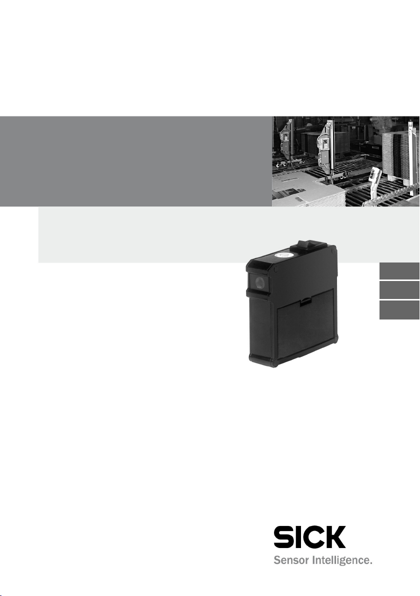
Abb.1:
Aufbau der Laser
-
Anschraubfläche
Micro
-
Ein-/Ausschalter
Lichtaustritt
ca. 6 mm
Zum Wechseln der Batterien
Deckel abnehmen
Nivellierlibelle
Kapitel 1 Betriebsanleitung
Allgemeines
AR60
1 Allgemeines
Die Laser-Ausrichthilfe AR60 ist ein Gerät, um verschiedene optische
Sensoren von SICK auszurichten, wie z. B. Lichtschranken und Lichtvorhänge.
1.1 Die Laser-Ausrichthilfe AR60 auf einen Blick
• Kleines Gehäuse.
• Netzunabhängig durch Batterie-Stromversorgung1).
• Anschraubfläche für verschiedene Adapter.
• Handlicher Laserpointer.
Ausrichthilfe AR60
batterien
2 x 1,5 V
LASERSTRAHLUNG
Nicht in den Strahl blicken!
LASERKLASSE 2
P ≤ 1 mW (cw), λ = 630-680 nm
Entsprich t IEC/EN 60825 -1:2007,
und21 CFR 1040.10 and1040.11mit
Ausnahme derAb weichungen gemäß
Laser Not ice No. 50, 24 . Juni 2007
Mit der Laser-Ausrichthilfe AR60 können die optischen Sensoren
(Sender/Empfänger) bei der Montage auf einfache Weise und zeitsparend ausgerichtet werden – schon bevor die Sensoren mit Spannung versorgt werden.
Sehr vorteilhaft ist die Laser-Ausrichthilfe AR60, wenn mittels
Umlenkspiegel das Lichtbündel umgelenkt wird. Die Ausrichtung
(Einjustierung) von Sender/Empfänger und Umlenkspiegel lässt sich
somit von einer Person in kürzester Zeit durchführen.
1)
Batterien sind n ach den gesetzli chen Vorschriften getrennt zu en tsorgen.
4 © SICK AG • Industrial Safety Systems • Deutschland • Alle Rechte vorbehalten 8007406/YW24/2016-05-13
Irrtümer und Änderungen vorbehalten
Page 5

de
Hinweis
Betriebsanleitung Kapitel 1
AR60
ACHTUNG
Allgemeines
Blicken Sie nie direkt in den Laserstrahl!
Die Laserstrahlung ist bei zufälliger, kurzzeitiger Einwirkung (< 0,25 s)
für das Auge ungefährlich. Eine Gefahr für das Auge besteht nur
dann, wenn die eigene Abwendreaktion gegenüber blendendem Licht
unterdrückt wird. Falls Laserstrahlung ins Auge trifft, schließen Sie
die Augen bewusst und wenden sich sofort ab.
Richten Sie niemals den Laserstrahl in die Augen von Personen.
Warnhinweis!
Vorsicht – wenn andere als die hier angegebenen Bedienungs- oder
Justiereinrichtungen benutzt oder andere Verfahrensweisen ausgeführt werden, kann dies zu gefährlicher Strahlungsexposition führen.
1.2 Einsatzbereiche
Die Laser-Ausrichthilfe AR60 ist auch für die effiziente Störungsbeseitigung sowie für Service- und Wartungsarbeiten von Vorteil.
Über verschiedene Adapter können die unterschiedlichen Geräte
ausgerichtet werden. Für folgende Gerätebaureihen sind Adapter
erhältlich:
Sicherheitstechnik
• miniTwin
• WSU/WEU26/3
• L21
• L40
• L41
• C2000, C4000, M2000, M4000
• L27
Automatisierungstechnik
• V18
• V18L
• V180-2
• W24-2
• W27-3
• W34
• W36
• W45
• W260
Bei Lichtschranken oder Lichtvorhängen mit Schutzfeldhöhen
″ 750 mm empfiehlt sich die Ausrichtung mit zwei Laser-
Ausrichthilfen AR60, angebracht an den Geräteenden.
8007406/YW24/2016-05-13 © SICK AG • Industrial Safety Systems • Deutschland • Alle Rechte vorbehalten 5
Irrtümer und Änderungen vorbehalten
Page 6

de
Kapitel 2 Betriebsanleitung
Justiervorgang
AR60
2 Justiervorgang
= Den dem Sensor entsprechenden Adapter an AR60 anschrauben.
= AR60 vor Sender montieren (fest aufklipsen oder anschrauben).
= AR60 einschalten.
= Auf dem Empfänger einen weißen Karton bzw. Karton mit
Scotchlite (Reflexionsband) anbringen (Lichtbündel ist so besser zu
erkennen).
= Sender so ausrichten, dass das Lichtbündel auf die Mitte der
Empfängeroptik trifft.
= Sender in dieser Position befestigen.
= AR60 vor Empfänger montieren und Empfänger so auf den Sender
ausrichten, dass das Lichtbündel auf die Mitte der Senderoptik
trifft.
= Empfänger in dieser Position befestigen.
= AR60 ausschalten.
= AR60 abmontieren.
= Sensoren einschalten.
Bei der Laser-Ausrichthilfe AR60 kann ein deutlich schwächerer zweiter Lichtfleck auftreten. Bei Abständen über 3 m ist dieser nicht mehr
sichtbar. In Abständen unter 3 m darf dieser nicht zur Ausrichtung
verwendet werden.
6 © SICK AG • Industrial Safety Systems • Deutschland • Alle Rechte vorbehalten 8007406/YW24/2016-05-13
Irrtümer und Änderungen vorbehalten
Page 7
de
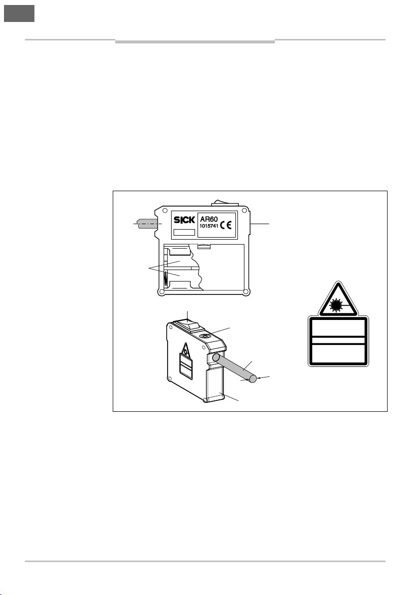
Abb.2:
Laser-Ausrichthilfe
Abb.3:
Laser-Ausrichthilfe
WSU/WEU26/3
Befestigungs
-
schraube M4 x 10
Adapter für
Laser-Ausricht
-
hilfe AR60
Sender
Empfänger
Adapter für L27
oder WS/WE27
-
3
Befestigungs
-
schraube M4 x 10
L27 oder
Laser-Ausricht
-
hilfe AR60
Sender
Empfänger
Betriebsanleitung Kapitel 2
Justiervorgang
AR60
AR60 und EinstrahlSicherheits-Lichtschranke
WSU/WEU26/3
WSU/WEU26/3
AR60 und EinstrahlSicherheits-Lichtschranke
L27 oder WS/WE27-3
8007406/YW24/2016-05-13 © SICK AG • Industrial Safety Systems • Deutschland • Alle Rechte vorbehalten 7
Irrtümer und Änderungen vorbehalten
WS/WE27-3
Page 8
de
Abb.4:
Laser-Ausrichthilfe
miniTwin
Befestigungs
-
schraube
Adapter für
Laser-Ausricht
-
hilfe AR60
Kapitel 2 Betriebsanleitung
Justiervorgang
AR60
AR60 und SicherheitsLichtvorhang miniTwin
miniTwin
8 © SICK AG • Industrial Safety Systems • Deutschland • Alle Rechte vorbehalten 8007406/YW24/2016-05-13
Irrtümer und Änderungen vorbehalten
Page 9
de
Abb.5:
Laser-Ausrichthilfe
C2000/C4000/M2000
Befestigungs
-
schraube M4 x 10
Laser-Ausricht
-
hilfe AR60
Adapter für Sender
C2000/C4000/M2000
Sender
Empfänger
Betriebsanleitung Kapitel 2
Justiervorgang
AR60
AR60 und SicherheitsLichtvorhänge
C2000/C40 00 bzw.
Mehrstrahl-SicherheitsLichtschranke M2000
8007406/YW24/2016-05-13 © SICK AG • Industrial Safety Systems • Deutschland • Alle Rechte vorbehalten 9
Irrtümer und Änderungen vorbehalten
Page 10
de
Abb.6:
Laser-Ausrichthilfe
M4000
Befestigungs
-
Adapter für
Laser-Ausricht
-
Sender
Empfänger
Kapitel 2 Betriebsanleitung
Justiervorgang
AR60
AR60 und MehrstrahlSicherheits-Lichtschranke
M4000
schraube
M4 x 10
M4000
10 © SICK AG • Industrial Safety Systems • Deutschland • Alle Rechte vorbehalten 8007406/YW24/2016-05-13
hilfe AR60
Irrtümer und Änderungen vorbehalten
Page 11
Ausrichtung über
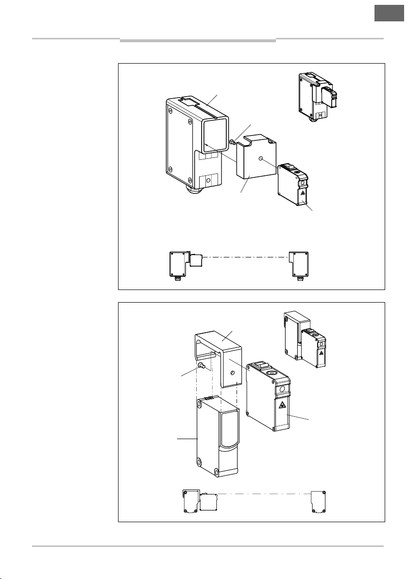
Abb.7:
Ausrichtung
einer
AR60
AR60
Sender
Empfänger
Umlenkspiegel
Umlenkspiegel
Betriebsanleitung Kapitel 3
AR60
Umlenkspiegel
3 Ausrichtung über Umlenkspiegel
= Adapter an AR60 montieren.
= AR60 vor Sender montieren.
= AR60 einschalten.
= Auf dem Umlenkspiegel einen weißen Karton bzw. Karton mit
Scotchlite (Reflexionsband) anbringen (Lichtbündel ist so besser zu
sehen).
= Sender so ausrichten, dass Lichtbündel in die Mitte des
Umlenkspiegels trifft.
= Sender in dieser Position befestigen.
WSU/WEU26/3 über
Umlenkspiegel
de
8007406/YW24/2016-05-13 © SICK AG • Industrial Safety Systems • Deutschland • Alle Rechte vorbehalten 11
Irrtümer und Änderungen vorbehalten
= Karton vor (erstem) Umlenkspiegel entfernen.
= Karton vor zweitem Umlenkspiegel anbringen.
= Ersten Umlenkspiegel so ausrichten, dass das Lichtbündel auf die
Mitte des zweiten Umlenkspiegels trifft.
= Ersten Umlenkspiegel in dieser Position befestigen.
= Karton vor zweitem Umlenkspiegel entfernen.
= Zweiten Umlenkspiegel so ausrichten, dass das Lichtbündel auf die
Mitte der Empfängeroptik trifft, evtl. einen weißen Karton bzw.
Karton mit Scotchlite (Reflexionsband) anbringen.
= Zweiten Umlenkspiegel in dieser Position festschrauben.
= Karton wieder vor zweitem Umlenkspiegel anbringen.
= AR60 vor den Empfänger montieren.
= Empfänger so ausrichten, dass das Lichtbündel auf die Mitte des
zweiten Umlenkspiegels trifft.
= Empfänger in dieser Position festschrauben.
= AR60 ausschalten.
= AR60 abmontieren.
= Sender und Empfänger einschalten.
Page 12
de
Tab.1:
Technische Daten
Kapitel 4 Betriebsanleitung
Technische Daten
AR60
4 Technische Daten
Laser-Ausrichthilfe AR60
Spannungsversorgung 3 V
Batterie 2 Stück
Betriebsdauer Batterien ca. 10 h
Schutzart IP 20
Gehäuse Aluminium
Reichweite (je nach
Reflexionsmaterial und
Umgebungshelligkeit)
Lichtquelle Halbleiter-
Optische Leistung ′ 1 mW
Wellenlänge (Rotlicht) 630 nm 680 nm
Lichtbündeldurchmesser ca. 6 mm
Lagertemperatur 0 °C 55 °C
Betriebsumgebungs-
temperatur
Laserklasse 2 nach
IEC/EN 60825-1:2007
Minimal Typisch Maximal
1,5 V
Micro/AAA
60 m
Laser
0 °C 40 °C
12 © SICK AG • Industrial Safety Systems • Deutschland • Alle Rechte vorbehalten 8007406/YW24/2016-05-13
Irrtümer und Änderungen vorbehalten
Page 13

de
Tab.2:
Artikelnummer
Tab.3:
Artikelnummern
Betriebsanleitung Kapitel 5
Bestelldaten
AR60
5 Bestelldaten
5.1 Laser-Ausrichthilfe AR60
Laser-Ausrichthilfe AR60
Adapter
Artikel Artikelnummer
Laser-Ausrichthilfe AR60 1015741
5.2 Adapter
Artikel Artikelnummer
Sicherheitstechnik
Für miniTwin 4064710
Für WSU/WEU26/3 4031156
Für L21/L40/L41, M30 5311529
Für L21/L40/L41, M18 5313533
Für M4000 4040006
Für C4000 Standard/Advanced/Basic/Basic Plus/
Eco/Host-Guest/Entry-Exit/Palletizer/Fusion und
C/M2000 mit Schutzfeldhöhe 1350 ... 1800 mm
(großes Gehäuse)
Für C4000 Standard/Advanced/Basic/Basic Plus/
Eco/Host-Guest/Entry-Exit/Palletizer/Fusion und
C/M2000 mit Schutzfeldhöhe 1350 ... 1800 mm
(großes Gehäuse) in PU3Hxx-xxxxxxxx Gerätesäule
Für C2000, C4000 Micro
(kleines Gehäuse)
Für C2000, C4000 Micro
(kleines Gehäuse) in PU3Hxx-xxxxxxxx Gerätesäule
Für L27 4056329
Automatisierungstechnik
Für V18/V18L/V180-2 5313533
Für W24-2 4032976
Für W27-3 4056329
Für W34 4032976
Für W36 2017376
Für W45 2017377
Für W260 2017726
4032461
4056731
4032462
4056730
8007406/YW24/2016-05-13 © SICK AG • Industrial Safety Systems • Deutschland • Alle Rechte vorbehalten 13
Irrtümer und Änderungen vorbehalten
Page 14

de
Kapitel 6 Betriebsanleitung
Anhang
AR60
6 Anhang
6.1 Tabellenverzeichnis
Tab. 1: Technische Daten Laser-Ausrichthilfe AR60.........................12
Tab. 2: Artikelnummer Laser-Ausrichthilfe AR60..............................13
Tab. 3: Artikelnummern Adapter....................................................... 13
6.2 Abbildungsverzeichnis
Abb. 1: Aufbau der Laser-Ausrichthilfe AR60...................................... 4
Abb. 2: Laser-Ausrichthilfe AR60 und Einstrahl-Sicherheits-
Lichtschranke WSU/WEU26/3................................................ 7
Abb. 3: Laser-Ausrichthilfe AR60 und Einstrahl-Sicherheits-
Lichtschranke L27 oder WS/WE27-3..................................... 7
Abb. 4: Laser-Ausrichthilfe AR60 und Sicherheits-Lichtvorhang
miniTwin...................................................................................8
Abb. 5: Laser-Ausrichthilfe AR60 und Sicherheits-Lichtvorhänge
C2000/C4000 bzw. Mehrstrahl-Sicherheits-
Lichtschranke M2000............................................................. 9
Abb. 6: Laser-Ausrichthilfe AR60 und Mehrstrahl-Sicherheits-
Lichtschranke M4000........................................................... 10
Abb. 7: Ausrichtung einer WSU/WEU26/3 über Umlenkspiegel.......11
6.3 Konformität mit EU-Richtlinien
EU-Konformitätserklärung (Auszug)
Der Unterzeichner, der den nachstehenden Hersteller vertritt, erklärt
hiermit, dass das Produkt in Übereinstimmung mit den Bestimmungen der nachstehenden EU-Richtlinie(n) (einschließlich aller zutreffenden Änderungen) ist, und dass die entsprechenden Normen und/oder
technischen Spezifikationen zugrunde gelegt sind.
Vollständige EU-Konformitätserklärung zum Download: www.sick.com
14 © SICK AG • Industrial Safety Systems • Deutschland • Alle Rechte vorbehalten 8007406/YW24/2016-05-13
Irrtümer und Änderungen vorbehalten
Page 15

Operating Instructions
AR60
en
List of Contents
1 General ......................................................................................... 16
1.1 The AR60 at a Glance......................................................... 16
1.2 Applications ........................................................................ 17
2 Alignment Procedure .................................................................. 18
3 Alignment via Deflector Mirrors ................................................. 23
4 Technical Specifications............................................................. 24
5 Ordering Information................................................................... 25
5.1 AR60 Laser Alignment Aid.................................................. 25
5.2 Adapter ............................................................................... 25
6 Appendix....................................................................................... 26
6.1 List of Tables....................................................................... 26
6.2 List of Illustrations .............................................................. 26
6.3 Compliance with EU directives ........................................... 26
8007406/YW24/2016-05-13 © SICK AG • Industrial Safety Systems • Germany • All rights reserved 15
Subject to change without notice
Page 16

en
Fig.1:
Construction of the
Connection screw
Micro
-
On/Off switch
Light emission
approx. 6 mm
Remove cover to
change batter
y
Spirit level
Chapter 1 Operating Instructions
General
AR60
1 General
The AR60 laser alignment aid is a device for aligning various SICK
optical sensors, such as for example photoelectric switches and light
curtains.
1.1 The AR60 at a Glance
• Compact housing.
• Battery power supply – no need for mains power1).
• Surface to which various adapters can be screwed.
• Easy-to-handle laser pointer.
AR60 laser alignment aid
battery
2 x 1.5 V
LASER RADIATION
DO NOT STARE INTO BEAM
CLASS 2 LASER PRODUCT
P ≤ 1 mW (cw), λ= 630-680nm
Compliesw ithIEC/EN 60825-1:2007,
21 CFR 1040.10and 1040.11 exceptfor
deviationspursuant to Laser Notice
No. 50,dated June 24, 2007
Using the AR60 laser alignment aid, optical sensors (sender/receiver)
may be quickly and easily aligned during installation, even before
power is supplied to the sensors.
The AR60 laser alignment aid is of great advantage when the beam
array is deflected by means of deflector mirrors. The alignment
(adjustment) of sender/receiver and deflector mirrors can thus be
carried out very rapidly by one person.
1)
Batteries are t o be disposed of separa tely in accordance with s tatutory regul ations.
16 © SICK AG • Industrial Safety Systems • Germany • All rights reserved 8007406/YW24/2016-05-13
Subject to change without notice
Page 17

en
Note
Operating Instructions Chapter 1
AR60
WARNING
General
Never look directly into the laser beam!
The laser beam is not dangerous for the eye in case of accidental,
brief exposure (< 0.25 s). There is only a hazard for the eye if the
normal blinking reaction to bright light is suppressed. If the laser
beam is incident on your eye, consciously close your eyes and turn
away immediately.
Never point the laser beam at people’s eyes.
Warning!
Caution – use of controls, adjustments or performance of procedures
other than those herein specified may result in hazardous radiation
exposure.
1.2 Applications
The AR60 laser alignment aid is also useful for efficient fault
elimination and in servicing and maintenance work.
Various adapters are used in aligning the different devices.
Adapters are available for the following device ranges:
Industrial Safety Systems
• miniTwin
• WSU/WEU26/3
• L21
• L40
• L41
• C2000, C4000, M2000, M4000
• L27
Industrial Sensors
• V18
• V18L
• V180-2
• W24-2
• W27-3
• W34
• W36
• W45
• W260
For photoelectric switches or light curtains with protective field
heights ″ 750 mm, it is recommended that two AR60 laser alignment
aids, fitted to the ends of the device, are used for alignment.
8007406/YW24/2016-05-13 © SICK AG • Industrial Safety Systems • Germany • All rights reserved 17
Subject to change without notice
Page 18

en
Chapter 2 Operating Instructions
Alignment Procedure
AR60
2 Alignment Procedure
= Screw the adapter matching the sensor onto the AR60.
= Mount the AR60 in front of the sender (clip it on firmly or screw it
on).
= Switch on the AR60.
= Fit a white card or a card covered with Scotchlite (reflective tape)
on the receivers (this makes the beam array easier to detect).
= Align the sender so that the beam array strikes the centre of the
receiver optic.
= Fix sender in this position.
= Mount AR60 in front of the receiver and align sender on receiver,
so that the beam array strikes the centre of the sender.
= Fix receiver in this position.
= Switch off AR60.
= Detach AR60.
= Switch on sensors.
When using the AR60 laser alignment aid an additional light spot of
lower intensity might appear. When using for distances above 3 m
this spot becomes invisible. When used for distances below 3 m this
spot should not be used for alignment purposes.
18 © SICK AG • Industrial Safety Systems • Germany • All rights reserved 8007406/YW24/2016-05-13
Subject to change without notice
Page 19

en
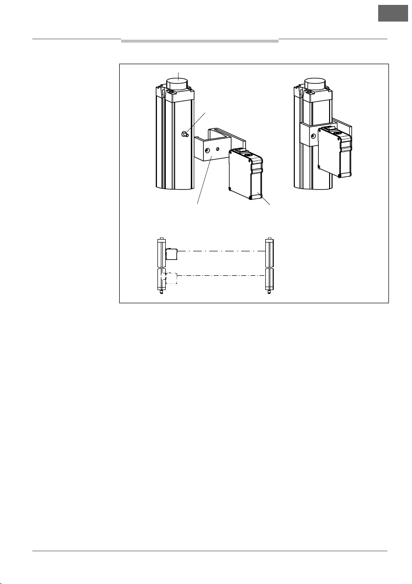
Fig.2:
AR60 l
aser
Fig.3:
AR60 laser
WSU/WEU26/
3
Fastening screw
M4 x 10
Adapter for
AR60 laser
Sender
Receiver
Adapter for L27 or
WS/WE27
-
3
Fastening scr ew
M4 x 10
L27 or
AR60 laser
Sender
Receiver
Operating Instructions Chapter 2
Alignment Procedure
AR60
alignment aid and
WSU/WEU26/3 singlebeam photoelectric safety
switch
WSU/WEU26/3
alignment aid
alignment aid and L27 or
WS/WE27-3 single-beam
photoelectric safety switch
8007406/YW24/2016-05-13 © SICK AG • Industrial Safety Systems • Germany • All rights reserved 19
Subject to change without notice
alignment aid
WS/WE27-3
Page 20

en
Fig.4:
AR60 laser
miniTwin
Fastening screw
Adapter for
AR60 laser
alignment aid
Chapter 2 Operating Instructions
Alignment Procedure
AR60
alignment aid and
miniTwin safety light
curtain
miniTwin
20 © SICK AG • Industrial Safety Systems • Germany • All rights reserved 8007406/YW24/2016-05-13
Subject to change without notice
Page 21

en
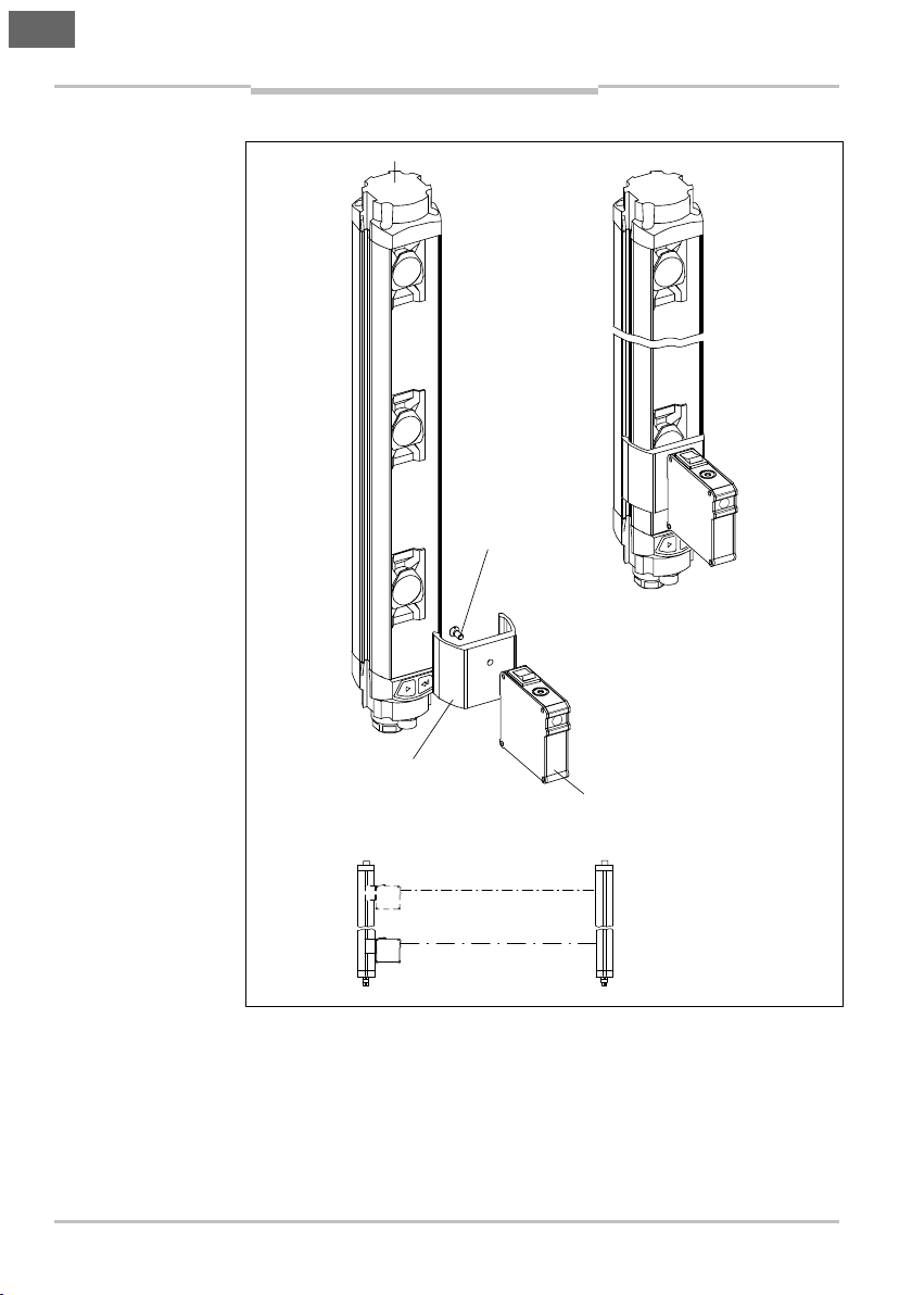
Fig.5:
AR60 laser
C2000/C4000/
M2000
Fastening scr ew
M4 x 10
AR60 laser
Adapter for sender
C2000/C4000/M2000
Sender
Receiver
Operating Instructions Chapter 2
Alignment Procedure
AR60
alignment aid and
C2000/C4000 safety light
curtains and M2000
multiple light beam safety
device
alignment aid
8007406/YW24/2016-05-13 © SICK AG • Industrial Safety Systems • Germany • All rights reserved 21
Subject to change without notice
Page 22

en
Fig.6:
AR60 laser
M4000
Fastening screw
Adapter for
AR60 laser
Sender
Receiver
Chapter 2 Operating Instructions
Alignment Procedure
AR60
alignment aid and M4000
multiple light beam safety
device
M4 x 10
M4000
22 © SICK AG • Industrial Safety Systems • Germany • All rights reserved 8007406/YW24/2016-05-13
alignment aid
Subject to change without notice
Page 23

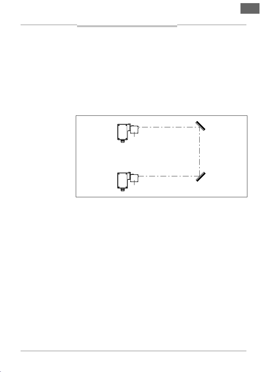
Alignment via Deflector
Fig.7:
Alignment of a
AR60
AR60
Sender
Receiver
Deflector mirr
or
Deflector mirror
Operating Instructions Chapter 3
AR60
Mirrors
3 Alignment via Deflector Mirrors
= Fit adapter to AR60.
= Mount AR60 in front of sender.
= Switch on AR60.
= Affix a piece of white card or a card covered with Scotchlite (reflec-
tive tape) to the deflector mirror (to make beam array more visible).
= Align sender so that beam array strikes the centre of the deflector
mirror.
= Fix sender in this position.
WSU/WEU26/3 via
deflector mirrors
= Remove card from (first) deflector mirror.
= Affix card in front of second deflector mirror.
= Align first deflector mirror so that the beam array strikes the centre
of the second deflector mirror.
= Fix first deflector mirror in this position.
= Remove card from second deflector mirror.
= Align second deflector mirror so that the beam array strikes the
centre of the receiver optics, if necessary affix white card or a card
covered with Scotchlite (reflective tape).
= Fix second deflector mirror in this position.
= Re-affix card to second deflector mirror.
= Mount AR60 in front of the receiver.
= Align receiver so that the beam array strikes the centre of the
second deflector mirror.
= Fix receiver in this position.
= Switch off AR60.
= Dismount AR60.
= Switch sender and receiver on.
en
8007406/YW24/2016-05-13 © SICK AG • Industrial Safety Systems • Germany • All rights reserved 23
Subject to change without notice
Page 24

en
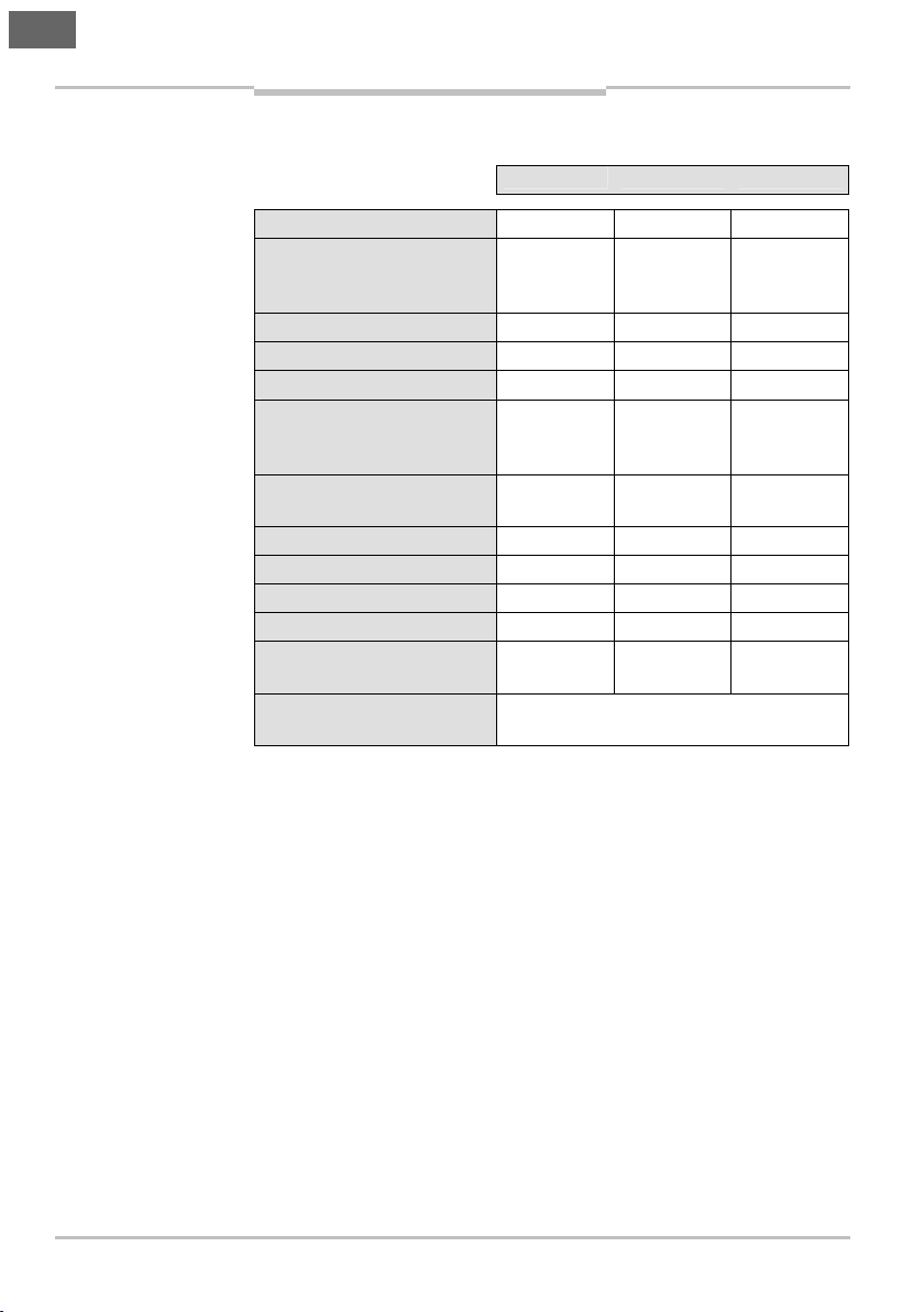
Tab.1:
Technical
Chapter 4 Operating Instructions
Technical Specifications
AR60
4 Technical Specifications
specifications AR60 laser
alignment aid
Voltage supply 3 V
Batteries 2 x 1.5 V
Battery life Approx.
Enclosure rating IP 20
Housing Aluminium
Scanning range
(depending on reflective
material and ambient
light)
Light source Semi-
Optical Power ′ 1 mW
Wavelength (red light) 630 nm 680 nm
Beam array diameter Approx.
Storage temperature 0 °C 55 °C
Ambient operating
temperature
Laser Class 2 to
IEC/EN 60825-1:2007
Minimum Typical Maximum
Micro/AAA
10 h
60 m
conductor
laser
6 mm
0 °C 40 °C
24 © SICK AG • Industrial Safety Systems • Germany • All rights reserved 8007406/YW24/2016-05-13
Subject to change without notice
Page 25

en
Tab.2:
Ordering
Tab.3:
Ordering
Operating Instructions Chapter 5
Ordering Information
AR60
5 Ordering Information
5.1 AR60 Laser Alignment Aid
information AR60 laser
alignment aid
information adapter
Article Part Number
AR60 laser alignment aid 1015741
5.2 Adapter
Article Part Number
Industrial Safety Systems
For miniTwin 4064710
For WSU/WEU26/3 4031156
For L21/L40/L41, M30 5311529
For L21/L40/L41, M18 5313533
For M4000 4040006
For C4000 Standard/Advanced/Basic/Basic Plus/Eco/
Host-Guest/Entry-Exit/Palletizer/Fusion and C/M2000
protective field heights from 1350 to 1800 mm
(large housing)
For C4000 Standard/Advanced/Basic/Basic Plus/Eco/
Host-Guest/Entry-Exit/Palletizer/Fusion and C/M2000
protective field heights from 1350 to 1800 mm
(large housing) in PU3Hxx-xxxxxxxx device column
For C2000, C4000 Micro
(small housing)
For C2000, C4000 Micro
(small housing) in PU3Hxx-xxxxxxxx device column
For L27 4056329
Industrial Sensors
For V18/V18L/V180-2 5313533
For W24-2 4032976
For W27-3 4056329
For W34 4032976
For W36 2017376
For W45 2017377
For W260 2017726
4032461
4056731
4032462
4056730
8007406/YW24/2016-05-13 © SICK AG • Industrial Safety Systems • Germany • All rights reserved 25
Subject to change without notice
Page 26

en
Chapter 6 Operating Instructions
Appendix
AR60
6 Appendix
6.1 List of Tables
Tab. 1: Technical specifications AR60 laser alignment aid...............24
Tab. 2: Ordering information AR60 laser alignment aid....................25
Tab. 3: Ordering information adapter.................................................25
6.2 List of Illustrations
Fig. 1: Construction of the AR60 laser alignment aid...................... 16
Fig. 2: AR60 laser alignment aid and WSU/WEU26/3 single-
beam photoelectric safety switch..........................................19
Fig. 3: AR60 laser alignment aid and L27 or WS/WE27-3 single-
beam photoelectric safety switch..........................................19
Fig. 4: AR60 laser alignment aid and miniTwin safety light
curtain....................................................................................20
Fig. 5: AR60 laser alignment aid and C2000/C4000 safety light
curtains and M2000 multiple light beam safety device.......21
Fig. 6: AR60 laser alignment aid and M4000 multiple light
beam safety device................................................................22
Fig. 7: Alignment of a WSU/WEU26/3 via deflector mirrors............23
6.3 Compliance with EU directives
EU declaration of conformity (excerpt)
The undersigned, representing the following manufacturer herewith
declares that the product is in conformity with the provisions of the
following EU directive(s) (including all applicable amendments), and
that the respective standards and/or technical specifications are
taken as the basis.
Complete EU declaration of conformity for download: www.sick.com
26 © SICK AG • Industrial Safety Systems • Germany • All rights reserved 8007406/YW24/2016-05-13
Subject to change without notice
Page 27

fr
Notice d’instructions
AR60
Sommaire
Sommaire
1 Généralités................................................................................... 28
1.1 Caractéristiques.................................................................. 28
1.2 Domaines d’utilisation........................................................ 29
2 Procédure de réglage .................................................................. 30
3 Alignement avec miroirs de renvoi............................................. 35
4 Caractéristiques techniques ...................................................... 36
5 Références................................................................................... 37
5.1 Outil d’alignement laser AR60 ........................................... 37
5.2 Adaptateur.......................................................................... 37
6 Annexe.......................................................................................... 38
6.1 Répertoire des tableaux ..................................................... 38
6.2 Répertoire des figures........................................................ 38
6.3 Conformité aux directives UE ............................................. 38
8007406/YW24/2016-05-13 © SICK AG • Industrial Safety Systems • Allemagne • Tous droits réservés 27
Sujet à modification san s préavis
Page 28

fr
Fig.1:
Plan de l’outil
Remarque
Vis de serrage
Piles
Interrupteur Marche/Arrêt
Sortie de lumière
env. 6 mm
Pour changer les piles,
démonter le couvercle
Niveau à bulle
Chapitre 1 Notice d’instructions
Généralités
AR60
1 Généralités
L’outil d’alignement laser AR60 est une cellule laser destinée à
faciliter l’alignement des barrières et barrages immatériels de SICK.
1.1 Caractéristiques
• Boîtier de petite taille.
• Alimentation par pile1).
• Possibilité de visser différents adaptateurs.
• Pointeur laser facile à manipuler.
d’alignement l aser AR60
2 x 1,5 V
RAYONS LASER
Ne pasregarder directement
dans lefaisceau !
LASER DE CLASSE 2
P ≤ 1 mW (cw),λ =630-680 nm
Conforme à CEI/E N 60825-1:200 7e t
21CFR 104 0.10an d1040.11à l‘exceptio n
des caractéristiq ues différentes selo nla
Notification La ser n° 50, 24 juin, 2007
L’outil d’alignement laser AR60 assure un alignement aisé et rapide
des cellules optiques (émetteur/récepteur) – avant même leur mise
sous tension.
Ce système s’avère très utile lorsque l’installation comporte des
miroirs de renvoi : une personne seule pourra effectuer l’alignement
(le réglage) de l’émetteur/récepteur et du miroir de renvoi, en un
temps réduit.
Ne jamais regarder directement dans le faisceau laser !
Pour une exposition accidentelle de courte durée (< 0,25 s), le
faisceau laser n’est pas dangereux pour l’œil. Il reste toutefois un
risque pour l’œil dans un cas : si le réflexe de détournement du
1)
Selon les pre scriptions légales, les b atteries doivent être éli minées dans des filières spécialisées.
28 © SICK AG • Industrial Safety Systems • Allemagne • Tous droits réservés 8007406/YW24/2016-05-13
Sujet à modification san s préavis
Page 29

fr
Notice d’instructions Chapitre 1
AR60
ATTENTION
Généralités
regard ne se produit pas en raison de l’effet de masque d’une forte
lumière ambiante. Si le faisceau laser atteint l’œil, immédiatement
fermer volontairement les paupières et détourner le regard.
Ne jamais diriger le faisceau laser dans l’œil d’autrui.
Attention !
Attention ! – l’utilisation d’instructions ou de réglages différents de
ceux préconisés ici ainsi que l’observation d’autres procédures
d’utilisation peuvent conduire au risque d’une exposition dangereuse
au rayon laser.
1.2 Domaines d’utilisation
L’outil d’alignement laser AR60 s’utilise également pour l’élimination
des défauts ainsi que pour les travaux d’entretien et de maintenance.
Des adaptateurs sont prévus pour l’alignement des appareils
suivants :
Sécurité industrielle
• miniTwin
• WSU/WEU26/3
• L21
• L40
• L41
• C2000, C4000, M2000, M4000
• L27
Automatisation
• V18
• V18L
• V180-2
• W24-2
• W27-3
• W34
• W36
• W45
• W260
Pour les barrières et barrages immatériels d’une hauteur de champ
de protection ″ 750 mm, il est conseillé d’utiliser deux outils
d’alignement laser AR60, un à chaque extrémité de l’appareil.
8007406/YW24/2016-05-13 © SICK AG • Industrial Safety Systems • Allemagne • Tous droits réservés 29
Sujet à modification san s préavis
Page 30

fr
Chapitre 2 Notice d’instructions
Procédure de réglage
AR60
2 Procédure de réglage
= Visser sur l’AR60 l’adaptateur correspondant au capteur.
= Monter l’AR60 devant l’émetteur (par encliquetage ou vissage).
= Allumer l’AR60.
= Devant le récepteur, placer une feuille blanche ou une feuille
réfléchissante de type scotchlite (pour une meilleure visibilité du
spot lumineux).
= Régler l’émetteur afin que le spot lumineux se trouve au milieu de
l’optique du récepteur.
= Fixer l’émetteur dans cette position.
= Monter l’AR60 devant le récepteur et aligner le récepteur sur
l’émetteur afin que le spot lumineux se trouve au milieu de
l’optique de l’émetteur.
= Fixer le récepteur dans cette position.
= Eteindre l’AR60.
= Démonter l’AR60.
= Mettre les capteurs sous tension.
L’outil d’alignement laser AR60 peut faire apparaître un deuxième
spot d‘intensité lumineuse beaucoup plus faible. Pour des distances
inférieures à 3 m, il ne faut pas aligner sur ce second spot, mais
uniquement tenir compte du spot d‘intensité lumineuse forte. Pour
des distances supérieures à 3 m, ce deuxième spot n‘est plus visible.
30 © SICK AG • Industrial Safety Systems • Allemagne • Tous droits réservés 8007406/YW24/2016-05-13
Sujet à modification san s préavis
Page 31

fr
Fig.2 :
Outil d’alignement
Fig.3:
Outil d’alignement
WSU/WEU26/3
Vis de fixation
M4 x 10
Adaptateur pour
Outil d’alignement
laser AR60
Emetteur
Récepteur
Adaptateur pour L27
ou WS/WE27
-
3
Vis de fixation
M4 x 10
L27 ou
Outil d’alignement
laser AR60
Emetteur
Récepteur
Notice d’instructions Chapitre 2
Procédure de réglage
AR60
laser AR60 et barrière
monofaisceau de sécurité
WSU/WEU26/3
WSU/WEU26/3
laser AR60 et barrière
monofaisceau de sécurité
L27 ou WS/WE27-3
8007406/YW24/2016-05-13 © SICK AG • Industrial Safety Systems • Allemagne • Tous droits réservés 31
Sujet à modification san s préavis
WS/WE27-3
Page 32

fr
Fig.4 :
Outil d’alignement
miniTwin
Vis de fixation
Adaptateur
Outil d’alignement
Chapitre 2 Notice d’instructions
Procédure de réglage
AR60
laser AR60 et barrage
immatériel de sécurité
miniTwin
pour
emetteur
miniTwin
laser AR60
32 © SICK AG • Industrial Safety Systems • Allemagne • Tous droits réservés 8007406/YW24/2016-05-13
Sujet à modification san s préavis
Page 33

fr
F
ig.5:
Outil d’alignement
C2000/C4000/M2000
Vis de fixation
M4 x 10
Outil d’alignement
laser AR60
Adaptateur pour emetteur
Emetteur
Récepteur
Notice d’instructions Chapitre 2
Procédure de réglage
AR60
laser AR60 et barrages
immatériels de sécurité
C2000/C4000 et barrière
de sécurité multi-faisceau
M2000
C2000/C4000/M2000
8007406/YW24/2016-05-13 © SICK AG • Industrial Safety Systems • Allemagne • Tous droits réservés 33
Sujet à modification san s préavis
Page 34

fr
Fig.6:
Outil d’alignement
M4000
Vis de fixation
Adaptateur pour
Outil d’alignement
Emetteur
Récepteur
Chapitre 2 Notice d’instructions
Procédure de réglage
AR60
laser AR60 et barrière de
sécurité multi-faisceau
M4000
M4 x 10
M4000
34 © SICK AG • Industrial Safety Systems • Allemagne • Tous droits réservés 8007406/YW24/2016-05-13
laser AR60
Sujet à modification san s préavis
Page 35

Alignement avec miroirs de
Fig.7:
Alignement d’un
AR60
AR60
Emetteur
Récepteur
Miroir de renvoi
Miroir de renvoi
Notice d’instructions Chapitre 3
AR60
renvoi
3 Alignement avec miroirs de renvoi
= Monter l’adaptateur sur l’AR60.
= Monter l’AR60 devant l’émetteur.
= Allumer l’AR60.
= Devant le miroir de renvoi, placer une feuille blanche ou une feuille
réfléchissante de type scotchlite (pour une meilleure visibilité du
spot lumineux).
= Régler l’émetteur afin que le spot lumineux se trouve au milieu du
miroir de renvoi.
= Fixer l’émetteur dans cette position.
WSU/WEU26/3 avec
miroirs de renvoi
fr
8007406/YW24/2016-05-13 © SICK AG • Industrial Safety Systems • Allemagne • Tous droits réservés 35
Sujet à modification san s préavis
= Eloigner la feuille du premier miroir de renvoi.
= Placer la feuille devant le deuxième miroir de renvoi.
= Régler le premier miroir de renvoi afin que le spot lumineux se
trouve au milieu du deuxième miroir de renvoi.
= Fixer le premier miroir de renvoi dans cette position.
= Eloigner la feuille du deuxième miroir de renvoi.
= Régler le deuxième miroir de renvoi afin que le spot lumineux se
trouve au milieu de l’optique du récepteur; le cas échéant, utiliser
une feuille blanche ou une feuille réfléchissante de type scotchlite.
= Visser le deuxième miroir de renvoi dans cette position.
= Repositionner la feuille devant le deuxième miroir de renvoi.
= Monter l’AR60 devant le récepteur.
= Régler le récepteur afin que le spot lumineux se trouve au milieu du
deuxième miroir de renvoi.
= Fixer le récepteur dans cette position.
= Eteindre l’AR60.
= Démonter l’AR60.
= Mettre l’émetteur et le récepteur sous tension.
Page 36

fr
Tab.1:
Caractéristiques
Chapitre 4 Notice d’instructions
Caractéristiques techniques
AR60
4 Caractéristiques techniques
techniques outil
d’alignement l aser AR60
Alimentation 3 V
Pile 2 unités
Durée de vie des piles env. 10 h
Indice de protection IP 20
Boîtier Aluminium
Portée (selon matériau de
réflection et lumière
ambiante)
Source de lumière Laser à
Puissance du faisceau ′ 1 mW
Longueur d’onde (lumière
rouge)
Diamètre du spot
lumineux
Température de stockage 0 °C 55 °C
Température de service 0 °C 40 °C
Classe laser 2 selon
CEI/EN 60825-1:2007
Minimum Valeur type Maximum
1,5 V
Micro/AAA
60 m
sémiconducteur
630 nm 680 nm
env. 6 mm
36 © SICK AG • Industrial Safety Systems • Allemagne • Tous droits réservés 8007406/YW24/2016-05-13
Sujet à modification san s préavis
Page 37

fr
Tab.2:Référence outil
Tab.3:
Références
Notice d’instructions Chapitre 5
Références
AR60
5 Références
5.1 Outil d’alignement laser AR60
d’alignement l aser AR60
adaptateurs
Article Référence
Outil d’alignement laser AR60 1015741
5.2 Adaptateur
Article Référence
Sécurité industrielle
Pour miniTwin 4064710
Pour WSU/WEU26/3 4031156
Pour L21/L40/L41, M30 5311529
Pour L21/L40/L41, M18 5313533
Pour M4000 4040006
Pour C4000 Standard/Advanced/Basic/Basic Plus/
Eco/Host-Guest/Entry-Exit/Palletizer/Fusion et
C/M2000 avec d’une hauteur de champ de
protection 1350 ... 1800 mm (grand boîtier)
Pour C4000 Standard/Advanced/Basic/Basic Plus/
Eco/Host-Guest/Entry-Exit/Palletizer/Fusion et
C/M2000 avec d’une hauteur de champ de
protection 1350 ... 1800 mm (grand boîtier) dans la
colonne de protection PU3Hxx-xxxxxxxx
Pour C2000, C4000 Micro
(petit boîtier)
Pour C2000, C4000 Micro (petit boîtier) dans la
colonne de protection PU3Hxx-xxxxxxxx
Pour L27 4056329
Automatisation
Pour V18/V18L/V180-2 5313533
Pour W24-2 4032976
Pour W27-3 4056329
Pour W34 4032976
Pour W36 2017376
Pour W45 2017377
Pour W260 2017726
4032461
4056731
4032462
4056730
8007406/YW24/2016-05-13 © SICK AG • Industrial Safety Systems • Allemagne • Tous droits réservés 37
Sujet à modification san s préavis
Page 38

fr
Chapitre 6 Notice d’instructions
Annexe
AR60
6 Annexe
6.1 Répertoire des tableaux
Tab. 1 : Caractéristiques techniques outil d’alignement laser
AR60......................................................................................36
Tab. 2 : Référence outil d’alignement laser AR60 ............................. 37
Tab. 3 : Références adaptateurs........................................................37
6.2 Répertoire des figures
Fig. 1 : Plan de l’outil d’alignement laser AR60................................28
Fig. 2 : Outil d’alignement laser AR60 et barrière monofaisceau
de sécurité WSU/WEU26/3 .................................................. 31
Fig. 3 : Outil d’alignement laser AR60 et barrière monofaisceau
de sécurité L27 ou WS/WE27-3 ...........................................31
Fig. 4 : Outil d’alignement laser AR60 et barrage immatériel de
sécurité miniTwin...................................................................32
Fig. 5 : Outil d’alignement laser AR60 et barrages immatériels
de sécurité C2000/C4000 et barrière de sécurité multi-
faisceau M2000 .................................................................... 33
Fig. 6 : Outil d’alignement laser AR60 et barrière de sécurité
multi-faisceau M4000........................................................... 34
Fig. 7 : Alignement d’un WSU/WEU26/3 avec miroirs de renvoi.....35
6.3 Conformité aux directives UE
Déclaration de conformité UE (extrait)
Le soussigné, représentant le constructeur ci-après, déclare par la
présente que le produit est conforme aux exigences de la (des)
directive(s) de l’UE suivantes (y compris tous les amendements
applicables) et que les normes et/ou spécifications techniques
correspondantes ont servi de base.
Pour télécharger la Déclaration de conformité UE dans son
intégralité : www.sick.com
38 © SICK AG • Industrial Safety Systems • Allemagne • Tous droits réservés 8007406/YW24/2016-05-13
Sujet à modification san s préavis
Page 39

fr
Notice d’instructions Chapitre 6
Annexe
AR60
8007406/YW24/2016-05-13 © SICK AG • Industrial Safety Systems • Allemagne • Tous droits réservés 39
Sujet à modification san s préavis
Page 40

8007406/YW24/2016-05-13 ∙ REIPA/XX (2016-05) ∙ A5 sw int45
Australia
+61 3 9457 0600
Phone
1800 334 802 – tollfree
Austria
Phone +43 22 36 62 28 8-0
Belgium/Luxembourg
Phone +32 2 466 55 66
Brazil
+55 11 3215-4900
Phone
Canada
Phone +1 905 771 14 44
Czech Republic
Phone
+420 2 57 91 18 50
Chile
Phone +56 2 2274 7430
China
Phone +86 20 2882 3600
Denmark
+45 45 82 64 00
Phone
Finland
Phone
+358-9-2515 800
France
Phone +33 1 64 62 35 00
Gemany
+49 211 5301-301
Phone
Hong Kong
Phone +852 2153 6300
Hungary
Phone
+36 1 371 2680
India
+91 22 4033 8333
Phone
Israel
Phone
+972 4 6881000
Italy
+39 02 274341
Phone
Japan
Phone +81 3 5309 2112
Malaysia
+6 03 8080 7425
Phone
Mexico
Phone +52 472 748 9451
Netherlands
Phone +31 30 2044 000
New Zealand
Phone +64 9 415 0459
0800 222 278 – tollfree
Norway
Phone +47 67 81 50 00
Poland
+48 22 539 41 00
Phone
Romania
Phone
+40 356 171 120
Russia
+7 495 775 05 30
Phone
Singapore
Phone +65 6744 3732
Slovakia
Phone
+421 482 901201
Slovenia
Phone +386 591 788 49
South Africa
Phone +27 11 472 3733
South Korea
+82 2 786 6321
Phone
Spain
Phone +34 93 480 31 00
Sweden
Phone
+46 10 110 10 00
Switzerland
Phone +41 41 619 29 39
Taiwan
+886 2 2375-6288
Phone
Thailand
Phone +66 2645 0009
Turkey
Phone
+90 216 528 50 00
United Arab Emirates
+971 4 88 65 878
Phone
United Kingdom
Phone +44 1727 831121
USA
+1 800 325 7425
Phone
Vietnam
Phone +84 945452999
Detailed addresses and additional
representatives and agencies at
www.sick.com
SICK AG | Waldkirch | Germany | www.sick.com
 Loading...