

Page 1

AOS502 STS
Object Detection Systems
SUPPLEMENTARY OPERATING INSTRUCTIONS
Page 2

2
8017621/ZPQ5/2017-08-15|SICK
SUPPLEMENTARY OPERATING INSTRUCTIONS | AOS502 STS
Subject to change without notice
Product described
Product name: AOS502 STS
Document identification
Title: AOS502 STS Supplementary Operating Instructions
Status: 2017-08-15
Manufacturer
SICK AG
Erwin-Sick-Str. 1 · 79183 Waldkirch · Germany
Trademarks
IBM is a trademark of the International Business Machine Corporation.
only used here for identification purposes.
Original documents
The German version 8017619/ZPQ5 of this document is an original SICK AG
In case of doubt, contact SICK AG or your local agency.
Legal notes
Subject to change without notice
© SICK AG. All rights reserved
Part number: 8017621/ZPQ5
MS-DOS is a trademark of the Microsoft Corporation.
Windows is a trademark of the Microsoft Corporation.
Other product names in this document may also be trademarks and are
document.
SICK AG does not assume liability for the correctness of a non-authorized
translation.
Page 3

3
8017621/ZPQ5/2017-08-15|SICK
Subject to change without notice
SUPPLEMENTARY OPERATING INSTRUCTIONS | AOS502 STS
Contents
CONTENTS
1 About these operating instructions ..............................................................................5
1.1 Purpose of this document .................................................................................... 5
1.2 Target group ......................................................................................................... 5
1.3 Information depth ................................................................................................ 6
1.4 Abbreviations used ............................................................................................... 6
1.5 Symbols used ....................................................................................................... 7
2 Safety ..............................................................................................................................8
2.1 Qualified personnel .............................................................................................. 8
2.2 Applications of the system ................................................................................... 8
2.3 Intended use ......................................................................................................... 9
2.4 General safety notes and protective measures ................................................. 9
3 Product description .................................................................................................... 10
3.1 Scope of delivery ............................................................................................... 10
3.2 System components ......................................................................................... 11
3.3 System functionality .......................................................................................... 12
4 Project planning .......................................................................................................... 14
4.1 Monitoring fields and evaluation cases ........................................................... 14
4.1.1 Prepared evaluation cases (EVCs) .................................................... 14
4.1.2 Input and output signals .................................................................... 15
4.2 Dimensioning the monitoring fields ................................................................. 16
4.2.1 Size and alignment of the fields for crane-to-ship collision
protection ........................................................................................... 16
4.2.2 Size and alignment of the fields for crane-to-crane collision
protection ........................................................................................... 17
4.2.3 Size and position of the test fields .................................................... 18
4.3 Scan plane ......................................................................................................... 20
4.3.1 Parallelism of the scan plane ............................................................ 20
4.3.2 Inclination angle of the scan plane ................................................... 21
5 Mounting ..................................................................................................................... 22
5.1 Mounting the laser scanners ............................................................................ 22
5.1.1 Position of the laser scanners ........................................................... 22
5.1.2 Inclination of the laser scanners ....................................................... 22
5.1.3 Mounting on booms with encompassing trolley ............................... 23
5.2 Position of the test target ................................................................................. 24
5.3 Mounting the Flexi Soft control ........................................................................ 24
6 Electrical installation ................................................................................................. 25
6.1 Electrical connection ......................................................................................... 25
6.1.1 Connection by means of individual installation cables .................... 25
6.1.2 Connection by means of distributor box ........................................... 27
6.1.3 General notes about the cables ........................................................ 29
6.2 Input and output signals of the AOS502 STS system ..................................... 30
7 Commissioning ............................................................................................................ 32
7.1 Configuration ..................................................................................................... 32
7.2 Checking the stopping and warning response of the system ......................... 32
Page 4

CONTENTS
4
8017621/ZPQ5/2017-08-15|SICK
SUPPLEMENTARY OPERATING INSTRUCTIONS | AOS502 STS
Subject to change without notice
8 Electrical wiring diagram ............................................................................................ 33
9 Appendix ....................................................................................................................... 37
9.1 List of tables .......................................................................................................37
9.2 List of figures ......................................................................................................38
Page 5

ABOUT THESE OPERATING INSTRUCTIONS 1
5
8017621/ZPQ5/2017-08-15|SICK
Subject to change without notice
SUPPLEMENTARY OPERATING INSTRUCTIONS | AOS502 STS
1 About these operating instructions
Please read this chapter carefully before you begin working with this documentation and
the AOS502 STS.
1.1 Purpose of this document
These supplementary operating instructions are intended to give technical personnel of
the machine manufacturer or operator instructions on the safe mounting, configuration,
electrical installation, commissioning, operation, and maintenance of the AOS502 STS
object detection system.
Note
The supplementary operating instructions for the AOS502 STS object detection system
are only valid in conjunction with the underlying operating instructions for the AOS
Prime (8016731).
Unless otherwise specified in this document, the information in the underlying operating
instructions for the AOS Prime will apply.
1.2 Target group
These supplementary operating instructions are intended for persons who integrate the
AOS502 STS object detection system into a crane system, and initially commission and
operate it there. They are also intended for the planners, developers, and operators of
crane systems for the handling of goods and containers.
Page 6

1 ABOUT THESE OPERATING INSTRUCTIONS
6
8017621/ZPQ5/2017-08-15|SICK
SUPPLEMENTARY OPERATING INSTRUCTIONS | AOS502 STS
Subject to change without notice
1.3 Information depth
These supplementary operating instructions contain information about the AOS502 STS
system on the following topics:
• Product description
• Project planning
• Mounting
• Electrical installation
• Commissioning
When planning and using the AOS502 STS system, technical skills are also required that
are not covered by this document.
The applicable official and legal regulations at the application site must always be
complied with when operating the system.
Note
Further information about the device components used in the AOS502 STS can be found
in the accompanying operating instructions.
For carrying out the configuration and diagnostics of the AOS502 STS, you will need the
SOPAS SICK Engineering Tool (configuration software for the laser scanners), version
V 3.0 or higher, and the FSD Flexi Soft Designer (configuration and diagnostic software
for the control), version 1.7 or higher. Both of these tools are included in the scope of
delivery.
1.4 Abbreviations used
AOS
FSD
LMS
SOPAS
PLC
STS
Advanced object detection system
Flexi Soft Designer = software for Flexi Soft control for configuration and diagnostics
Laser scanner from SICK AG
SICK Engineering Tool = software for laser scanner configuration and diagnostics
Programmable logic controller
Ship-to-shore
Page 7

7
8017621/ZPQ5/2017-08-15|SICK
Subject to change without notice
SUPPLEMENTARY OPERATING INSTRUCTIONS | AOS502 STS
1.5 Symbols used
ABOUT THESE OPERATING INSTRUCTIONS 1
Recommendation
Note
1. / 2. ...
Step by step
Action
Recommendations are designed to assist you in the decision-making process with respect
to the use of a certain function or technical measure.
Notes provide information about the features of a device, application tips, or other useful
information.
Instructions that must be carried out in the described order are referred to as step-by-step
instructions and are indicated by numbered lists. Carefully read and follow the
instructions for action.
Instructions for taking action are indicated by an arrow. Carefully read and follow the
instructions for action.
Page 8

2 SAFETY
8
8017621/ZPQ5/2017-08-15|SICK
SUPPLEMENTARY OPERATING INSTRUCTIONS | AOS502 STS
Subject to change without notice
2 Safety
This chapter concerns your own safety and the safety of the system operator.
Please read through this chapter carefully before using the AOS502 STS or the crane
▸
system monitored by the AOS502 STS.
Note
2.1 Qualified personnel
Please also observe all safety notes contained in the operating instructions for the
components used.
The AOS502 STS must only be mounted, commissioned, and maintained by adequately
qualified personnel.
A qualified person
• has sufficient skills in the field of the respective equipment based on their technical
training and experience and
• has been instructed by the manufacturer in system operation and all applicable safety
guidelines and
• is familiar with all relevant country-specific occupational safety regulations, work safety
regulations, guidelines, and generally accepted technical rules and standards (e.g.,
DIN standards, VDE regulations, country-specific rules) to such an extent that he/she is
able to evaluate the safe condition of the power-driven machinery and he/she
• has access to and has read the operating instructions.
2.2 Applications of the system
The AOS502 STS object detection system is a collision protection system on ship-to-shore
crane systems or crane systems with a corresponding boom.
The system solution offers collision protection for the boom against ship constructions
with an upstream warning zone.
It offers additional collision protection with separate monitoring zones with respect to
neighboring cranes with lateral movements.
The ambient conditions typical in ports such as rain, snow, or fog, are mastered by the
AOS502 STS system.
Page 9

9
8017621/ZPQ5/2017-08-15|SICK
Subject to change without notice
SUPPLEMENTARY OPERATING INSTRUCTIONS | AOS502 STS
2.3 Intended use
NOTE
The AOS502 STS may only be used as described in section 2.2 Applications of the
system. The system may only be used by qualified personnel and only in industrial
environments in which it was installed and initially commissioned by qualified safety
personnel in accordance with these supplementary operating instructions.
Note
The AOS502 STS object detection system is not a safety device for human protection
and it therefore does not comply with any safety standards. For safety applications,
please contact SICK AG.
2.4 General safety notes and protective measures
These supplementary operating instructions must be made available to the operator of
the crane system on which the AOS502 STS system is used, along with the basic AOS
Prime underlying operating instructions.
The operator must be instructed by qualified safety personnel and read the operating
instructions.
SAFETY 2
Page 10
3 PRODUCT DESCRIPTION
10
8017621/ZPQ5/2017-08-15|SICK
SUPPLEMENTARY OPERATING INSTRUCTIONS | AOS502 STS
Subject to change without notice
Part No.
Quantity
Description
1064545
1
AOS502 STS
Consisting of:
Laser scanner
1057618
2
LMS511-10100S02 laser scanner
2063034
2
Connection box for power, I/O, and RS-232/RS-422 data
(not Ethernet), with three pre-wired M12 cables
2063050
2
Weather hood (180°), vertical mounting
2018303
2
Mounting kit for wall mounting (adjustment bracket)
2059271
2
Mounting bracket for mounting the laser scanner and
terminal box
6030928
2
Ethernet connection cable SSL-2J04-G10ME
Control
1043783
1
Flexi Soft main module FX3-CPU000000
1043700
1
Flexi Soft system plug FX3-MPL000001
1044125
2
Flexi Soft I/O module FX3-XTIO84002
6034574
1
Configuration cable DSL-8U04G02M025KM1 for connecting the
interface of the configuration PC
2073337
1
USB stick with configuration file (prepared configuration for control
and laser scanner) as well as device and system documentation
3 Product description
This chapter provides information on the special features of the AOS502 STS system.
It describes the construction and operating principle of the system, in particular the
interaction of the different components.
Note
3.1 Scope of delivery
Always read this chapter before you mount, install, and commission the system.
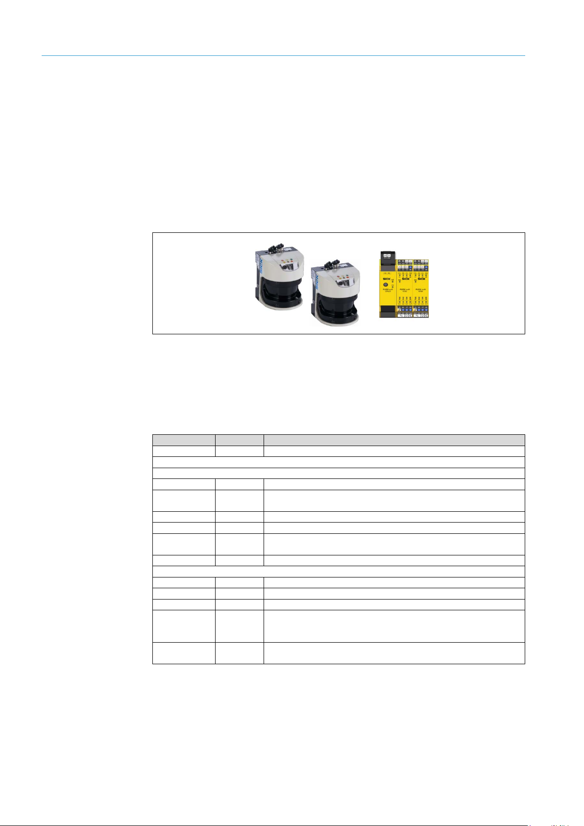
The AOS502 STS consists of two pre-configured LMS511 laser scanners and the
Flexi Soft control, which comprises the main module and two I/O expansion modules.
The system is supplied with the required accessories.
Important note
Fig. 1: Main components of the AOS502 STS
Thorough check for completeness
It is recommended that you carefully check for and report transport damage of any
▸
kind as soon as possible after receiving the system.
Also verify that the delivery includes all components listed on the delivery note.
▸
Tab. 1: Scope of delivery for the AOS502 STS
Note
The “SOPAS” and Flexi Soft Designer configuration tools can be downloaded at
www.sick.com.
configuration connection of the Flexi Soft control to the USB
Page 11
11
8017621/ZPQ5/2017-08-15|SICK
Subject to change without notice
SUPPLEMENTARY OPERATING INSTRUCTIONS | AOS502 STS
3.2 System components
All components of the AOS502 STS system are prepared for their use on crane systems
for the handling of goods and containers.
LMS511 laser scanner with weather hood
The LMS511 laser scanners are designed for outdoor use in harsh ambient conditions
and are fitted with a weather protection hood. All input and output signals from the laser
scanners are directly connected to the central Flexi Soft control.
Fig. 2: LMS511 laser scanner with weather hood
The LMS511 laser scanners have a monitoring radius of 80 m / 38 m for black objects
with 10% remission and a scan angle of 190°.
They feature automatic contamination measuring for the front screen. The contamination
signals can be merged using the central Flexi Soft control and can be output via a shared
application diagnostic output.
The laser scanners are also equipped with an internal heater.
The Flexi Soft control
The Flexi Soft control for the AOS502 STS system consists of the CPU0 central main
module with a configuration memory and two XTIO I/O expansion modules.
The two I/O expansion modules provide the input and output signals from the AOS502
STS. The communication with the connected laser scanners and with the higher-level
crane control occurs via the switching signals.
The test target
The self-diagnosis of the object detection system occurs via the continuous detection of
an external test target. During this process, the corresponding scanner monitoring field is
infringed by the test target. Only by using external test targets can the full functional range
of the AOS502 STS system be ensured.
At least one test target is required to continue the self-diagnosis of the system. It is also
possible to use a common test target for several laser scanners.
In crane applications, such as ship-to-shore crane systems, a part of the crane body is
defined as the test target.
PRODUCT DESCRIPTION 3
Page 12

3 PRODUCT DESCRIPTION
12
8017621/ZPQ5/2017-08-15|SICK
SUPPLEMENTARY OPERATING INSTRUCTIONS | AOS502 STS
Subject to change without notice
1
Crane-to-ship collision protection
2
Crane-to-crane collision protection
Configuration
The configuration file contains all the functions required to evaluate the system based on
the scenarios at the industrial cranes and to cyclically test the laser scanners.
It is located on the USB stick supplied and is loaded onto the Flexi Soft control via file
download.
The size and geometry of the monitoring fields must be adapted to the existing conditions
on-site.
3.3 System functionality
The AOS502 STS is a self-testing object detection system whose functionality as a whole
is monitored by the Flexi Soft control. During later movement by a boom (gantry travel),
the system prevents collisions with exposed ship superstructures, such as the radar
system, and between neighboring cranes.
The AOS502 STS provides protection against collisions by means of two laser scanners,
which are positioned on the right and left sides of the boom. These generate a horizontal
monitored area along the boom, which covers its entire length.
In addition, depending on the mounting process, the system offers protection from
collisions with neighboring cranes during lateral movements through the monitored areas
oriented to the rear.
Fig. 3: Typical layout of the monitored areas
Page 13

13
8017621/ZPQ5/2017-08-15|SICK
Subject to change without notice
SUPPLEMENTARY OPERATING INSTRUCTIONS | AOS502 STS
Note
PRODUCT DESCRIPTION 3
If an object is detected in the monitored area, the system sends a slow-down signal
(warning signal) to the crane, followed by a stop signal, in case the crane is to continue
traveling.
For this purpose, the output signals of the laser scanners are evaluated and processed by
the Flexi Soft control.
As an option, relays can be controlled for the purposes of electrical isolation, e.g., the
SICK UE10-3OS safety relay.
Page 14

4 PROJECT PLANNING
14
8017621/ZPQ5/2017-08-15|SICK
SUPPLEMENTARY OPERATING INSTRUCTIONS | AOS502 STS
Subject to change without notice
Evaluation case
Field
LMS output
1
Boom stop
1
2
Test 2 3
Boom stop
2
4
Test
1
5
Boom warning
3 6 Crane-to-crane stop
4
7
Field 5*
5
8
Field 6*
5 9 Not used
Not used
10
Not used
Not used
4 Project planning
4.1 Monitoring fields and evaluation cases
Monitoring fields
Evaluation cases
The scanned area of the laser scanners is divided into different fields, known as
monitoring fields. The size and geometry of the monitoring fields can vary and must be
configured on-site depending on the installation position and the alignment of the laser
scanners.
The monitoring fields are adapted using the SOPAS configuration software supplied.
Each monitoring field is linked to an evaluation case (EVC). An evaluation case determines
the way the monitoring field is evaluated and which switching output is addressed.
Evaluation cases can be activated via input signals depending on the required scenarios.
Ten different evaluation cases can be configured and permanently saved in each laser
scanner. Depending on the input signals that are present for the evaluation case, the
laser scanner switches between the cases.
Fig. 4: Activating an evaluation case
4.1.1 Prepared evaluation cases (EVCs)
Every laser scanner is prepared with eight evaluation cases for use in the AOS502 STS.
Tab. 2: Pre-configured evaluation cases and switching signals
Legend
* Field 5 and field 6 are for additional demand. They can be used as desired, e.g. for a second
warning on the boom.
Page 15

15
8017621/ZPQ5/2017-08-15|SICK
Subject to change without notice
SUPPLEMENTARY OPERATING INSTRUCTIONS | AOS502 STS
4.1.2 Input and output signals
All input and output signals from the laser scanners are directly connected to the
Flexi Soft control.
The Out 1 to Out 5 LMS outputs signal the status of the assigned monitoring field to the
respective inputs of the Flexi Soft control.
The Flexi Soft control analyzes the status signals from the laser scanners based on the
stored monitoring scenarios and transmits corresponding stop and warning signals to
the higher-level crane control.
PROJECT PLANNING 4
Note
Fig. 5: Interaction between the input and output signals
LMS output Out 6 is used to signal the contamination of the laser scanner to the Flexi Soft
control. If contamination is low, a warning is displayed; if contamination is high, an error is
displayed.
Page 16

4 PROJECT PLANNING
16
8017621/ZPQ5/2017-08-15|SICK
SUPPLEMENTARY OPERATING INSTRUCTIONS | AOS502 STS
Subject to change without notice
Monitoring field
Depth
Width
Boom stop
3.5 m
50 m (± 25 m symmetrical with the center
of the LMS)
Warning/Speed reduction boom
7.5 m
50 m (± 25 m symmetrical with the center
of the LMS)
4.2 Dimensioning the monitoring fields
With respect to their geometry, all monitoring fields must be adapted to the existing
conditions on-site.
The monitoring fields always start at the relevant laser scanner and span the stored
length and depth.
4.2.1 Size and alignment of the fields for crane-to-ship collision protection
The monitoring fields for the boom (crane-to-ship collision protection) are already predefined as rectangles in the SOPAS configuration software. Typically, you will simply have
to adapt the specific dimensions.
The pre-assignment assumes that the laser scanner is positioned roughly in the center
of the monitored area.
Warning field
Fig. 6: Size and alignment of the fields for crane-to-ship collision protection
By default, the monitoring fields for the booms are pre-defined with the following
dimensions:
Tab. 3: Field sizes for crane-to-ship collision protection
The depth of the fields is generally based on the response time of the crane and its
stopping distance.
Fig. 7: Size of the warning field
Increase or decrease the output field during the test drives systematically until the
▸
slowing-down and stop procedures start to converge.
Monitor the behavior of the crane during the test drives.
▸
Page 17

17
8017621/ZPQ5/2017-08-15|SICK
Subject to change without notice
SUPPLEMENTARY OPERATING INSTRUCTIONS | AOS502 STS
4.2.2 Size and alignment of the fields for crane-to-crane collision protection
The crane-to-crane collision protection can be used when the installation position and the
resulting inclination angle of the laser scanner allow this. Laser scanners with strong
inclination angles can only scan between the neighboring cranes to a certain degree. This
means a necessary stopping field cannot be completely covered.
A suitable layout for a stopping field can therefore not be determined. That is why the
evaluation cases and the stopping fields for the crane-to-crane collision protection are
predefined, but their geometries are not yet defined (empty).
The stopping fields should be wedge-shaped.
Due to the crane movements during operation, a suitable distance of the stopping field
to the crane body must be considered (distance d in the following figure). A minimum
distance of ≥ 0.5 m is recommended.
PROJECT PLANNING 4
Fig. 8: Size and alignment of the fields for crane-to-crane collision protection
If the distance is too small, the monitoring field will impinge on the crane body and trigger
a stop erroneously.
Fig. 9: Distance between stopping field and crane body too low
Page 18

4 PROJECT PLANNING
18
8017621/ZPQ5/2017-08-15|SICK
SUPPLEMENTARY OPERATING INSTRUCTIONS | AOS502 STS
Subject to change without notice
Monitoring field
Length
Width at maximum length
Scan angle
Test field right/left
35 m
4 m
7° symmetrical
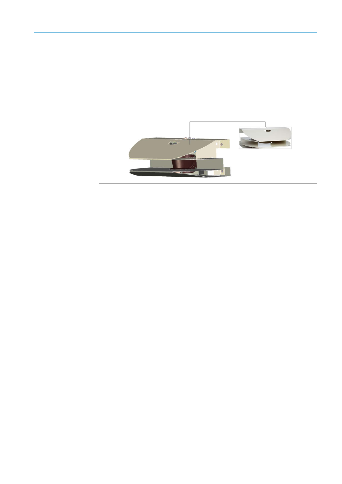
4.2.3 Size and position of the test fields
The system’s self-monitoring test fields are typically aligned with a suitable flat object
on the crane or directly with a flat area of the crane body. In the figure below, one of the
crane girders is used as the test target.
Fig. 10: Crane leg as test target
The test fields are pre-defined. They are formed as triangles and must be adapted to the
existing conditions on-site.
Fig. 11: Size and position of the test fields
By default, the test fields are pre-defined with the following dimensions in SOPAS:
Tab. 4: Field sizes for the test fields
Page 19

PROJECT PLANNING 4
19
8017621/ZPQ5/2017-08-15|SICK
Subject to change without notice
SUPPLEMENTARY OPERATING INSTRUCTIONS | AOS502 STS
The test fields on the right and left must clearly and reliably impinge on the crane girders.
Take into account tolerances resulting from mechanical movements.
In order to avoid reflections on the surface of the external test target, the area of the test
target must not be covered with a glossy coating.
Ideally, the test target should be outside the longest monitoring field (approx. 0.5 m from
the edge of the monitoring field). A standard value for the distance from the laser scanner
is > 0.5 m. The width of the test field on the test target must be at least 100 mm.
Fig. 12: Alignment of the test target on the crane body
Page 20

4 PROJECT PLANNING
20
8017621/ZPQ5/2017-08-15|SICK
SUPPLEMENTARY OPERATING INSTRUCTIONS | AOS502 STS
Subject to change without notice
Device
Accessories
Description
Part number
4.3 Scan plane
4.3.1 Parallelism of the scan plane
The scan plane of both laser scanners must be parallel to the boom (X = control
positions).
Fig. 13: Parallelism of the scan plane from the side
Larger deviations in terms of parallelism result in unintended shutdowns or detection
failures (X = control points).
Fig. 14: Incorrect scan plane from the side
Checking that the scan plane is correct
The scan plane can be correctly aligned using the scan finder, which you can order as
a SICK accessory.
LS80b scan finder
Infrared receiver for locating the
laser beam
6020756
Alternatively, you can place suitable objects at two control points and check the scan
plane in the live monitor of the SOPAS configuration software.
Deviations can be corrected by swiveling the laser scanner.
Page 21

21
8017621/ZPQ5/2017-08-15|SICK
Subject to change without notice
SUPPLEMENTARY OPERATING INSTRUCTIONS | AOS502 STS
4.3.2 Inclination angle of the scan plane
To enable the area below the boom to be fully monitored, the laser scanners are tilted
forward slightly to position the scan plane at an angle.
The extent of the inclination is subject to the selected mounting position. The further the
laser scanner is mounted from the lower edge, the greater the inclination must be.
The figure below illustrates the pre-set field sizes for the warning and stopping fields along
the boom from the side view.
PROJECT PLANNING 4
Fig. 15: Inclination of the monitoring fields from side view
The scan plane is to be determined taking the mounting position, set inclination, and
▸
the field dimensions of the warning and stopping fields into account.
Adapt the warning and stopping fields to the existing conditions on-site.
▸
Page 22

5 MOUNTING
22
8017621/ZPQ5/2017-08-15|SICK
SUPPLEMENTARY OPERATING INSTRUCTIONS | AOS502 STS
Subject to change without notice
5 Mounting
5.1 Mounting the laser scanners
The aim of the AOS502 STS is to avoid collisions with exposed ship superstructures and
with neighboring cranes.
The reliable and problem-free operation of the system depends primarily on the proper
planning and mounting of the laser scanners.
5.1.1 Position of the laser scanners
In principle, the laser scanners are positioned in the center of the working range. The
advantage of this is that the objects to be detected (such as ship superstructures or radar
systems) are relatively close to laser scanner. This ensures reliable detection.
Fig. 16: Mounting the laser scanners – central position on the boom
Note
Positioning the laser scanners centrally does not impair the lateral crane-to-crane collision
protection, as the crane bodies to be detected are relatively large objects for the laser
scanner and are always reliably detected.
5.1.2 Inclination of the laser scanners
To ensure that monitoring also takes place right up to the lower edge of the boom, it is
advisable to mount, for example, a bracket with extension so that the laser scanner can
be positioned lower down.
The expansion bracket should be able to be swiveled upward to provide better access.
Fig. 17: Mounting of the laser scanner with extended bracket and small inclination angle
Note
As the boom is raised up and down, you must ensure that the bracket demonstrates the
required stability, as the laser scanner will be swung along with it.
Page 23

23
8017621/ZPQ5/2017-08-15|SICK
Subject to change without notice
SUPPLEMENTARY OPERATING INSTRUCTIONS | AOS502 STS
5.1.3 Mounting on booms with encompassing trolley
On booms where the trolley travels all the way along, the laser scanners (1) must be
positioned above the rails for the trolley (2).
MOUNTING 5
Fig. 18: Mounting the laser scanners – boom with full-travel trolley
For this type of mounting, the laser scanner (1) must have a greater inclination to enable
the lower section of the boom to be monitored.
Take the distance of the monitoring field to the trolley (2) into account here.
▸
Fig. 19: Mounting the laser scanners – above the trolley with tilt angle
Page 24

5 MOUNTING
24
8017621/ZPQ5/2017-08-15|SICK
SUPPLEMENTARY OPERATING INSTRUCTIONS | AOS502 STS
Subject to change without notice
5.2 Position of the test target
Check whether there is a part of the crane (e.g., crane frame) that would be suitable for
use as a test target. If none can be found, mount a suitable test target.
5.3 Mounting the Flexi Soft control
The Flexi Soft control is situated in a suitable location in the control cabinet of the crane
control.
Note
Fig. 20: Mounting the control
In order to accommodate the leads and wiring of the signals, there must be enough free
terminals available in the control cabinet (see 6 Electrical installation).
Page 25

25
8017621/ZPQ5/2017-08-15|SICK
Subject to change without notice
SUPPLEMENTARY OPERATING INSTRUCTIONS | AOS502 STS
6 Electrical installation
HAZARD
HAZARD
Disconnect the power to the system
Make sure that all the components of the system are disconnected from the power
▸
supply during electrical installation work.
Risk of injury due to electrical current
Standard safety requirements must be met when working on electrical systems.
▸
The power supply must be disconnected when attaching and detaching electrical
▸
connections.
6.1 Electrical connection
The electrical connection between the Flexi Soft control and the individual laser scanners
is established by means of:
• Already-existing and suitable cables or
• Individual installation cables from the Flexi Soft control to the local connection box on
every laser scanner or
• Common installation cables with distributor boxes.
Note
6.1.1 Connection by means of individual installation cables
Shielded cables must always be used.
▸
ELECTRICAL INSTALLATION 6
If there are no free cables on the boom, separate and suitable cables are installed to the
voltage supply and transmit the I/O signals between the Flexi Soft control to the laser
scanners.
Cables with at least 9 wires are required. A cable cross-section of 1.5 mm
The wires can be connected directly in the local connection boxes of the laser scanners.
2
is sufficient.
Fig. 21: Electrical installation by means of separate stub cables
Page 26

6 ELECTRICAL INSTALLATION
26
8017621/ZPQ5/2017-08-15|SICK
SUPPLEMENTARY OPERATING INSTRUCTIONS | AOS502 STS
Subject to change without notice
Connecting wires in the connection box
The connection box contains a terminal strip with screw terminals.
Fig. 22: Local connection box on the LMS with screw terminals
Refer to the figure below for the pin assignment in the connection box terminal block.
▸
Fig. 23: Connection of the local terminal box (suggestion)
Notes
• The jumpers between terminals 10, 17, 20, and 22 and between terminals 18, 19, and
21 are to be placed on-site.
• If two separate power supply units are used for the sensor and the heater, terminals
19 to 21 and 20 to 22 are not bridged. The 0-V outputs of both power supply units
must be connected for potential equalization.
Page 27

ELECTRICAL INSTALLATION 6
27
8017621/ZPQ5/2017-08-15|SICK
Subject to change without notice
SUPPLEMENTARY OPERATING INSTRUCTIONS | AOS502 STS
Cable no. (in picture)
Laser scanner connection
1
I/O cable
2
Data/Input cable
3
Voltage supply
Connecting the laser scanner to the local connection box
The laser scanners are connected to the terminal box using pre-wired M12 plug
connectors. The connections cannot get mixed up.
Fig. 24: Connecting the laser scanner to the connection box
Tab. 5: Connecting the laser scanner to the connection box
6.1.2 Connection by means of distributor box
Alternatively, a shared cable for both laser scanners can be routed. This is then split in
a distributor (distributor box) close to the laser scanners and connected to the laser
scanners via the respective connection box.
The common cable to the distributor must have at least 17 wires. A cable cross-section
of 1.5 mm
2
is sufficient. A shielded cable must be used.
Fig. 25: Connection by means of distributor box
Page 28

6 ELECTRICAL INSTALLATION
28
8017621/ZPQ5/2017-08-15|SICK
SUPPLEMENTARY OPERATING INSTRUCTIONS | AOS502 STS
Subject to change without notice
Notes
• When using a common cable, signals of the same type are routed together in one wire
and are branched via the local distributor/distributor box to the laser scanner. The
voltage supply, ground, and control input of the laser scanner in question are routed
together as one signal.
• Shielded cables must always be used.
Connecting wires in the distributor box
Refer to the suggested pin assignment for the distributor box below.
▸
Fig. 26: Connection of a distributor box (suggestion)
Notes
• The jumpers between terminals 01 and 10, 02 and 11, and 3 and 12 are to be placed
on-site.
Page 29

29
8017621/ZPQ5/2017-08-15|SICK
Subject to change without notice
SUPPLEMENTARY OPERATING INSTRUCTIONS | AOS502 STS
6.1.3 General notes about the cables
Wire cross-sections of 1 mm
power requirement including the laser scanner heater may need to be taken into account.
Check the performance of the power supply unit.
▸
With long cables, also take the voltage drop that occurs when the heater is in operation
▸
into account.
Depending on the length of cable, wire cross-section of between 1 mm
sufficient here.
Note
The Flexi Soft control and the laser scanners must be connected to the same voltage
supply.
If using multiple power supplies, a 0 V potential equalization between the individual power
supplies must be established.
To do this, establish 0 V connections for all power supply units.
▸
ELECTRICAL INSTALLATION 6
2
are sufficient for the I/O signals. For the voltage supply, the
2
and 2.5 mm2 are
Page 30

6 ELECTRICAL INSTALLATION
30
8017621/ZPQ5/2017-08-15|SICK
SUPPLEMENTARY OPERATING INSTRUCTIONS | AOS502 STS
Subject to change without notice
Expansion module
Output (Flexi Soft)
Function
Q1
Stop LMS 1
boom and crane-to-crane collision protection
Q2
Stop LMS 2
boom and crane-to-crane collision protection
Q3
Warning/Speed reduction LMS 1
boom
Q4
Warning/Speed reduction LMS 2
boom
Q1
Not connected
Q2
Test error LMS 1 or LMS 2
(flashing)
Q3
Contamination LMS 1 or LMS 2
(flashing)
Q4
Test command on LMS 1 and LMS 2
Expansion module
Output (Flexi Soft)
Function
Q1
Stop LMS 1
boom
Q2
Stop LMS 2
boom
Q3
Stop LMS 1, crane-to-crane collision protection
Q4
Stop LMS 2, crane-to-crane collision protection
Q1
Warning/Speed reduction boom
(common output)
Q2
Test error LMS 1 or LMS 2
(flashing)
Q3
Contamination LMS 1 or LMS 2
(flashing)
Q4
Test command on LMS 1 and LMS 2
Expansion module
Output (Flexi Soft)
Function
Q1
Stop LMS 1,
boom/crane-to-crane collision protection
Q2
Stop LMS 2,
boom/crane-to-crane collision protection
Q3
Not connected
Q4
Not connected
Q1
Warning/Speed reduction boom
(common output)
Q2
Test error LMS 1 or LMS 2
(flashing)
Q3
Contamination LMS 1 or LMS 2
(flashing)
Q4
Test command on LMS 1 and LMS 2
6.2 Input and output signals of the AOS502 STS system
All output signals of the AOS502 STS are provided in the Flexi Soft control.
The arrangement of the output signal always depends on the actual configuration.
Depending on the requirement, three different configurations are provided for the system.
Output signals of configuration 1
XTIO 1
XTIO 2
Tab. 6: Output signals of configuration 1
Output signals of configuration 2
XTIO 1
XTIO 2
Tab. 7: Output signals of configuration 2
Output signals of configuration 3
XTIO 1
XTIO 2
Tab. 8: Output signals of configuration 3
Page 31

ELECTRICAL INSTALLATION 6
31
8017621/ZPQ5/2017-08-15|SICK
Subject to change without notice
SUPPLEMENTARY OPERATING INSTRUCTIONS | AOS502 STS
Configuration
File name
crane_separate WARNING outputs left-right.fsp
crane_common WARNING output.fsp
crane_common WARNING output.fsp
Expansion module
Input (Flexi Soft)
Source
I1
LMS 1 OUT 1
I2
LMS 1 OUT 2
I3
LMS 1 OUT 3
I4
LMS 1 OUT 4
I5
LMS 1 OUT 5
I6
LMS 1 OUT 6
I7
Not connected
I8
Not connected
I1
LMS 2 OUT 1
I2
LMS 2 OUT 2
I3
LMS 2 OUT 3
I4
LMS 2 OUT 4
I5
LMS 2 OUT 5
I6
LMS 2 OUT 6
I7
Not connected
I8
Not connected
All three configurations can be downloaded as files.
Configuration 1
Configuration 2
Configuration 3
Tab. 9: Configuration files for download
AOS502STS_2LMS_2XTIO_common STOP outputs for Boom and crane-to-
AOS502STS_2LMS_2XTIO_separated STOP outputs for Boom and crane-to-
AOS502STS_2LMS_2XTIO_common STOP outputs for Boom and crane-to-
Assignment of the input signals
The input assignment is the same for all configurations.
XTIO 1
XTIO 2
Note
Tab. 10: Pin assignment of the input signals
All stop and warning outputs operate active low. The output signal has the status High
(+24 V) when the monitoring fields are clear. If an object is detected in a monitoring field,
the associated output switches from High to Low (0 V).
Page 32

7 COMMISSIONING
32
8017621/ZPQ5/2017-08-15|SICK
SUPPLEMENTARY OPERATING INSTRUCTIONS | AOS502 STS
Subject to change without notice
7 Commissioning
7.1 Configuration
The AOS502 STS is configured using the SOPAS configuration software and the Flexi Soft
Designer.
LMS - SOPAS
The monitoring fields and evaluation cases required to prevent collisions are already
available in the laser scanners. The response times for normal system operation are predefined.
Adapt the geometry of the monitoring fields to the existing conditions on-site.
▸
You can find additional information on configuration of the laser scanners and using the
SOPAS configuration software in the AOS Prime operating instructions.
Flexi Soft
The configuration required to operate the AOS502 STS system is available in the project
file on the USB stick supplied.
With the aid of the Flexi Soft Designer, transfer the configuration via file download to
▸
the Flexi Soft control.
You can find additional information on downloading the configuration files with the
Flexi Soft Designer in the AOS Prime operating instructions or in the separate Flexi Soft
QuickStart instructions on the USB stick.
7.2 Checking the stopping and warning response of the system
During system construction, there will generally be no ship beneath the crane. The system
shutdown behavior can however be checked by placing corresponding objects in the
individual fields.
Checking crane-to-ship collision protection
Use simple equipment, such as lasher bars with an object attached, to actively infringe
▸
the individual monitoring fields.
Checking crane-to-crane collision protection
Use simple equipment, such as lasher bars with an object attached, to actively infringe
▸
the individual monitoring fields.
Recommendation
If possible, move the crane sideways toward the neighboring crane and check that the
▸
behavior is correct.
If the stop signal is too early or too late, adapt the geometry of the stopping field
▸
accordingly.
Checking stop and warning signals
Check whether the behavior of the output signals of the system to the inputs of the
▸
crane control (usually PLC) is correct
Page 33

33
8017621/ZPQ5/2017-08-15|SICK
Subject to change without notice
SUPPLEMENTARY OPERATING INSTRUCTIONS | AOS502 STS
8 Electrical wiring diagram
ELECTRICAL WIRING DIAGRAM 8
Page 34

8 ELECTRICAL WIRING DIAGRAM
34
8017621/ZPQ5/2017-08-15|SICK
SUPPLEMENTARY OPERATING INSTRUCTIONS | AOS502 STS
Subject to change without notice
Page 35

ELECTRICAL WIRING DIAGRAM 8
35
8017621/ZPQ5/2017-08-15|SICK
Subject to change without notice
SUPPLEMENTARY OPERATING INSTRUCTIONS | AOS502 STS
Page 36

8 ELECTRICAL WIRING DIAGRAM
36
8017621/ZPQ5/2017-08-15|SICK
SUPPLEMENTARY OPERATING INSTRUCTIONS | AOS502 STS
Subject to change without notice
Page 37

37
8017621/ZPQ5/2017-08-15|SICK
Subject to change without notice
SUPPLEMENTARY OPERATING INSTRUCTIONS | AOS502 STS
9 Appendix
9.1 List of tables
Tab. 1: Scope of delivery for the AOS502 STS .............................................................. 10
Tab. 2: Pre-configured evaluation cases and switching signals ................................... 14
Tab. 3: Field sizes for crane-to-ship collision protection ............................................... 16
Tab. 4: Field sizes for the test fields .............................................................................. 18
Tab. 5: Connecting the laser scanner to the connection box ....................................... 27
Tab. 6: Output signals of configuration 1 ....................................................................... 30
Tab. 7: Output signals of configuration 2 ....................................................................... 30
Tab. 8: Output signals of configuration 3 ....................................................................... 30
Tab. 9: Configuration files for download ........................................................................ 31
Tab. 10: Pin assignment of the input signals ................................................................... 31
APPENDIX 9
Page 38

9 APPENDIX
38
8017621/ZPQ5/2017-08-15|SICK
SUPPLEMENTARY OPERATING INSTRUCTIONS | AOS502 STS
Subject to change without notice
9.2 List of figures
Fig. 1: Main components of the AOS502 STS ...............................................................10
Fig. 2: LMS511 laser scanner with weather hood ........................................................11
Fig. 3: Typical layout of the monitored areas ................................................................12
Fig. 4: Activating an evaluation case .............................................................................14
Fig. 5: Interaction between the input and output signals .............................................15
Fig. 6: Size and alignment of the fields for crane-to-ship collision protection ............16
Fig. 7: Size of the warning field ......................................................................................16
Fig. 8: Size and alignment of the fields for crane-to-crane collision protection ..........17
Fig. 9: Distance between stopping field and crane body too low .................................17
Fig. 10: Crane leg as test target .......................................................................................18
Fig. 11: Size and position of the test fields .....................................................................18
Fig. 12: Alignment of the test target on the crane body .................................................19
Fig. 13: Parallelism of the scan plane from the side ......................................................20
Fig. 14: Incorrect scan plane from the side .....................................................................20
Fig. 15: Inclination of the monitoring fields from side view ............................................21
Fig. 16: Mounting the laser scanners – central position on the boom ..........................22
Fig. 17: Mounting of the laser scanner with extended bracket and small
Fig. 18: Mounting the laser scanners – boom with full-travel trolley .............................23
Fig. 19: Mounting the laser scanners – above the trolley with tilt angle .......................23
Fig. 20: Mounting the control ...........................................................................................24
Fig. 21: Electrical installation by means of separate stub cables ..................................25
Fig. 22: Local connection box on the LMS with screw terminals ...................................26
Fig. 23: Connection of the local terminal box (suggestion) ............................................26
Fig. 24: Connecting the laser scanner to the connection box ........................................27
Fig. 25: Connection by means of distributor box .............................................................27
Fig. 26: Connection of a distributor box (suggestion) .....................................................28
inclination angle ..................................................................................................22
Page 39

APPENDIX 9
39
8017621/ZPQ5/2017-08-15|SICK
Subject to change without notice
SUPPLEMENTARY OPERATING INSTRUCTIONS | AOS502 STS
Page 40

8017621/ZPQ5/2017-08-15 ∙ DOCOM/ITL (2017-11) ∙ A4 4c int46
Australia
Phone +61 3 9457 0600
1800 334 802 – tollfree
E-Mail sales@sick.com.au
Austria
Phone +43 22 36 62 28 8-0
E-Mail office@sick.at
Belgium/Luxembourg
Phone +32 2 466 55 66
E-Mail info@sick.be
Brazil
Phone +55 11 3215-4900
E-Mail marketing@sick.com.br
Canada
Phone +1 905 771 14 44
E-Mail information@sick.com
Czech Republic
Phone +420 2 57 91 18 50
E-Mail sick@sick.cz
Chile
Phone +56 2 2274 7430
E-Mail info@schadler.com
China
Phone +86 20 2882 3600
E-Mail info.china@sick.net.cn
Denmark
Phone +45 45 82 64 00
E-Mail sick@sick.dk
Finland
Phone +358-9-2515 800
E-Mail sick@sick.fi
France
Phone +33 1 64 62 35 00
E-Mail info@sick.fr
Germany
Phone +49 211 5301-301
E-Mail info@sick.de
Hong Kong
Phone +852 2153 6300
E-Mail ghk@sick.com.hk
Hungary
Phone +36 1 371 2680
E-Mail office@sick.hu
India
Phone +91 22 4033 8333
E-Mail info@sick-india.com
Israel
Phone +972 4 6881000
E-Mail info@sick-sensors.com
Italy
Phone +39 02 274341
E-Mail info@sick.it
Japan
Phone +81 3 5309 2112
E-Mail support@sick.jp
Malaysia
Phone +6 03 8080 7425
E-Mail enquiry.my@sick.com
Mexico
Phone +52 472 748 9451
E-Mail mario.garcia@sick.com
Netherlands
Phone +31 30 2044 000
E-Mail info@sick.nl
New Zealand
Phone +64 9 415 0459
0800 222 278 – tollfree
E-Mail sales@sick.co.nz
Norway
Phone +47 67 81 50 00
E-Mail sick@sick.no
Poland
Phone +48 22 539 41 00
E-Mail info@sick.pl
Romania
Phone +40 356 171 120
E-Mail office@sick.ro
Russia
Phone +7 495 775 05 30
E-Mail info@sick.ru
Singapore
Phone +65 6744 3732
E-Mail sales.gsg@sick.com
Slovakia
Phone +421 482 901201
E-Mail mail@sick-sk.sk
Slovenia
Phone +386 591 788 49
E-Mail office@sick.si
South Africa
Phone +27 11 472 3733
E-Mail info@sickautomation.co.za
South Korea
Phone +82 2 786 6321
E-Mail info@sickkorea.net
Spain
Phone +34 93 480 31 00
E-Mail info@sick.es
Sweden
Phone +46 10 110 10 00
E-Mail info@sick.se
Switzerland
Phone +41 41 619 29 39
E-Mail contact@sick.ch
Taiwan
Phone +886 2 2375-6288
E-Mail sales@sick.com.tw
Thailand
Phone +66 2645 0009
E-Mail Ronnie.Lim@sick.com
Turkey
Phone +90 216 528 50 00
E-Mail info@sick.com.tr
United Arab Emirates
Phone +971 4 88 65 878
E-Mail info@sick.ae
United Kingdom
Phone +44 1727 831121
E-Mail info@sick.co.uk
USA
Phone +1 800 325 7425
E-Mail info@sick.com
Vietnam
Phone +84 945452999
E-Mail Ngo.Duy.Linh@sick.com
Further locations at www.sick.com
SICK AG | Waldkirch | Germany | www.sick.com
 Loading...