

Page 1

AOS301-WWD
Object detection systems
OPERATING INSTRUCTIONS
Page 2

2
8023732/2018-09-10|SIC K
ORIGINAL OPERA TING INSTRUCT IONS | AOS301-WWD
Subject to change without notice
Product described
Product name: AOS301-WWD
Document identification
Title: AOS301-WWD operating instructions
Status: 2018-09-10
Manufacturer
SICK AG
Erwin-Sick-Str. 1 · 79183 Waldkirch · Germany
Legal notes
Original documents
This document is an original document of SICK AG.
Part number 8023732
This work is protected by copyright. The associated rights are reserved by SICK AG.
Reproduction of this document or parts of this document is only permissible within
the limits of the legal provisions of copyright law. Any modification, abridgment, or
translation of this document is prohibited without the express written permission of
SICK AG.
The trademarks mentioned in this document are the property of their respective
owners.
© SICK. All rights reserved
Page 3

3
8023732/2018-09-10|SIC K
Subject to change without notice
ORIGINAL OPERA TING INSTRUCT IONS | AOS301-WWD
Contents
CONTENTS
1 About this document ........................................................................................................ 6
1.1 Limitation of liability ............................................................................................. 6
1.2 Purpose of this document .................................................................................... 6
1.3 Target groups........................................................................................................ 6
1.4 Further information .............................................................................................. 7
1.5 Other relevant technical documentation/information ....................................... 7
1.6 Document conventions ........................................................................................ 7
2 Important safety notes ..................................................................................................... 8
2.1 Safety conventions ............................................................................................... 8
2.2 Supplementary safety note .................................................................................. 8
2.3 Requirements for the qualification of personnel................................................ 8
2.4 Intended use ......................................................................................................... 9
2.5 RoHS directive ...................................................................................................... 9
2.6 Safety notes ....................................................................................................... 10
3 System description ........................................................................................................ 11
3.1 Scope of delivery ............................................................................................... 11
3.2 System components.......................................................................................... 14
3.2.1 RMS3xx radar sensor......................................................................... 14
3.2.2 TDC-E200xx telematic data collector ................................................ 15
3.3 Operating principle ............................................................................................ 16
3.3.1 Vehicle detection and evaluation ...................................................... 16
3.3.2 Data output and interfaces ............................................................... 18
3.4 Project planning ................................................................................................ 19
3.5 System extension with tools and customer-specific applications .................. 22
4 Mounting ........................................................................................................................ 23
4.1 Mounting the RMS3xx ....................................................................................... 23
4.1.1 Mounting with holding bracket .......................................................... 24
4.1.2 Mounting via wall holder .................................................................... 25
4.1.3 Mounting with weather protection hood ........................................... 26
4.2 Mounting TDC-E ................................................................................................. 27
4.2.1 Mounting on a plate ........................................................................... 27
4.2.2 Mounting on DIN mounting rails ....................................................... 27
4.2.3 Inserting SIM card .............................................................................. 29
5 Electrical installation .................................................................................................... 31
5.1 Connection overview ......................................................................................... 31
5.2 Connecting the RMS3xx and TDC-E to the voltage supply .............................. 32
5.3 Connecting radar sensor to TDC-E ................................................................... 33
5.4 Connecting customer interface ........................................................................ 34
6 Commissioning .............................................................................................................. 35
6.1 Starting the system ........................................................................................... 35
6.2 Preparing the configuration PC ........................................................................ 36
6.3 Using TEMS Manager ........................................................................................ 37
6.3.1 Starting TEMS Manager ..................................................................... 37
6.3.2 Using a configuration file to load standard parameters .................. 37
6.3.3 The user interface .............................................................................. 38
Page 4

CONTENTS
4
8023732/2018-09-10|SIC K
ORIGINAL OPERA TING INSTRUCT IONS | AOS301-WWD
Subject to change without notice
6.3.4 Displaying the measurement site ......................................................40
6.3.5 Activating expert mode .......................................................................42
6.3.6 Displaying system parameters ...........................................................42
6.3.7 Visualizing radar measurement points and monitored area in
the live view .........................................................................................44
6.4 Adapting system parameters in TEMS Manager ..............................................45
6.4.1 Switching to editing mode ..................................................................45
6.4.2 Configuring the measurement site ....................................................46
6.4.3 Configuring radar sensor (system function RMS320) ......................48
6.4.4 Configuring monitored area (AOS RMS system function) .................50
6.4.5 Defining expected direction of travel (WWD system function) .........52
6.5 Configuring data output in TEMS Manager ......................................................53
6.5.1 Configuring I/O interface (TDC-E IO plug-in) ......................................53
6.5.2 Configuring call-up of MQTT messages .............................................57
6.6 Configuring in TEMS Manager ...........................................................................61
6.6.1 Checking proper measuring operation in TEMS Manager ................61
6.6.2 Save configuration ..............................................................................62
6.7 Checking measurement operation is working properly ...................................63
6.7.1 Displaying vehicles with measured values ........................................63
6.7.2 Accessing detailed information about a vehicle ...............................64
6.7.3 Saving vehicle data .............................................................................66
6.8 Using TDC Device Manager ...............................................................................67
6.8.1 Starting TDC-E Device Manager .........................................................67
6.8.2 The configuration interface ................................................................67
6.8.3 Adjusting Ethernet interface for data output ....................................68
6.8.4 Configuring wireless settings .............................................................69
7 Maintenance and repair ................................................................................................70
7.1 Visual inspection ................................................................................................70
7.2 Cleaning radar sensor........................................................................................71
7.3 Replacing the RMS3xx .......................................................................................72
7.4 Replacing TDC-E .................................................................................................73
8 Fault diagnosis ...............................................................................................................74
8.1 Fault diagnosis in TEMS Manager ....................................................................74
8.1.1 Warning and fault visualization ..........................................................74
8.1.2 Analyzing the error situation ..............................................................76
8.1.3 Detecting system errors using log files..............................................77
8.2 TDC-E Device Manager fault diagnosis .............................................................79
8.2.1 Displaying logs ....................................................................................79
8.2.2 Events ..................................................................................................80
8.2.3 Checking the network connection .....................................................80
9 Annex ...............................................................................................................................81
9.1 Technical data ....................................................................................................81
9.1.1 AOS301 data sheet ............................................................................81
9.1.2 RMS-343300 data sheet (excerpt) ....................................................82
9.1.3 TDC-E200 data sheet (excerpt) ..........................................................83
9.2 Dimensional drawings .......................................................................................84
9.2.1 RMS3xxx ..............................................................................................84
9.2.2 TDC-E ...................................................................................................86
Page 5

CONTENTS
5
8023732/2018-09-10|SIC K
Subject to change without notice
ORIGINAL OPERA TING INSTRUCT IONS | AOS301-WWD
9.3 Users and authorizations .................................................................................. 87
9.3.1 TDC-E Device Manager ...................................................................... 87
9.3.2 TEMS Manager ................................................................................... 88
9.4 TDC-E pin assignments ..................................................................................... 92
10 Disposal .......................................................................................................................... 93
Page 6

1 ABOUT THIS DOCUMENT
6
8023732/2018-09-10|SIC K
ORIGINAL OPERA TING INSTRUCT IONS | AOS301-WWD
Subject to change without notice
1 About this document
This document contains information that is required during the life cycle of the
AOS301-WWD (wrong way detection) object detection system.
The document must be made available to all those who work with the system.
▸
Read through the document carefully and ensure that you have full understood
▸
the content before working with the system.
1.1 Limitation of liability
Applicable standards and regulations, the latest technological developments, and
our many years of knowledge and experience have all been taken into account when
assembling the data and information contained in this document.
The manufacturer accepts no liability for damage caused by:
• Failure to observe this document.
• Non-compliance with notes and regulations.
• Unauthorized mounting and installation.
• Unauthorized technical and other changes.
• Use of unauthorized spare parts, wear and tear parts, and accessories.
• Unauthorized changes, adjustments and/or manipulations of software.
With special variants, where optional extras have been ordered, or owing to the latest
technical changes, the actual scope of delivery may differ from the features and
illustrations shown here.
1.2 Purpose of this document
The document is designed to give technical personnel instructions on the safe mounting,
parameterization, electrical installation, commissioning, operation, and maintenance of
the AOS301-WWD system.
1.3 Target groups
This document is intended for qualified persons who perform the following tasks with the
AOS301-WWD system
• Installation
• Commissioning
• Operating
• Repairing
Page 7

7
8023732/2018-09-10|SIC K
Subject to change without notice
ORIGINAL OPERA TING INSTRUCT IONS | AOS301-WWD
1.4 Further information
Special local conditions
The local laws, regulations, technical rules and internal company operating instructions
at the usage site must be observed.
Storage of documents
This document and other relevant technical documentation/information:
• Must be kept available for reference.
• Must be handed on to new operating entities/new specialist personnel.
1.5 Other relevant technical documentation/information
• Operating instructions for the following system components:
Component Manufacturer
ABOUT THIS DOCUMENT 1
RMS3xx radar measurement sensor operating
instructions
TDC-E (telematic data collector) operating
instructions
Technical information “Regulatory Compliance
Information”
Table 1: Other relevant technical documentation/information
1.6 Document conventions
Instructions.
▸
Instructions completed.
LED icons describe the status of a diagnostics LED.
SICK
SICK
SICK
Page 8

2 IMPORTANT SAFETY NOTES
8
8023732/2018-09-10|SIC K
ORIGINAL OPERA TING INSTRUCT IONS | AOS301-WWD
Subject to change without notice
2 Important safety notes
Read and observe all safety notes in this document.
▸
2.1 Safety conventions
Safety symbols on the system and on the system components, as well as safety notes
and safety labels, correspond to the current guidelines and standards.
The safety conventions for signal words used in this document correspond with
ANSI Z535.
DANGER! Refers to a hazard with a high level of risk that will result in serious injury
or death if not avoided.
WARNING! Refers to a hazard with a medium level of risk that may result in serious
injury or death if not avoided.
CAUTION! Refers to a hazard with a low level of risk that will result in a minor or
moderate injury if not avoided.
NOTE! indicates possible damage to property or material damage and useful information.
2.2 Supplementary safety note
WARNING!
Only qualified persons from the relevant departments are permitted to work on the
▸
system.
Follow operating processes.
▸
Follow local regulations.
▸
Only authorized persons are permitted to access the system.
▸
2.3 Requirements for the qualification of personnel
• Qualified persons have the specialist training, skills, and experience, as well as
knowledge of the relevant regulations and standards, to be able to perform work
assigned to them and to identify and avoid any potential dangers independently.
• Electricians have the professional training, skills and experience, and knowledge
of the relevant standards and provisions to work on electrical systems and to detect
and avoid any potential dangers independently.
Page 9

9
8023732/2018-09-10|SIC K
Subject to change without notice
ORIGINAL OPERA TING INSTRUCT IONS | AOS301-WWD
2.4 Intended use
The AOS301-WWD is an object detection system which uses a a radar sensor to identify
vehicles which move against the permitted direction of travel.
If an wrong-way driver is reliably detected in a defined monitoring area, a digital signal is
output to the customer system via the I/O interface.
In addition, the measurement data of the detected vehicles can be called up via a cloud
server in the form of MQTT messages. Data is transmitted via Ethernet or wireless
networks.
WARNING! The AOS301-WWD object detection system must only be used for the intended
purpose. Non-intended use of the system can pose a hazard to people and cause damage
to the system.
2.5 RoHS directive
This system has been designed for specific applications in industrial plants according to
article 2 (4) e, RoHS 2011/65 / EU, and must therefore only be used in such plants.
The product is neither suited nor certified for use outside of these plants. SICK therefore
cannot assume any type of warranty or liability for such use.
IMPORTANT SAFETY NOTES 2
Page 10

2 IMPORTANT SAFETY NOTES
10
8023732/2018-09-10|SIC K
ORIGINAL OPERA TING INSTRUCT IONS | AOS301-WWD
Subject to change without notice
▸
▸
2.6 Safety notes
DANGER!
HAZARDOUS ELECTRICAL VOLTAGE
The system is supplied with mains voltage. Risk of electric shocks. Contact causes
death, burns or shock.
Only qualified specialist personnel may conduct electrical work on the system.
▸
Interrupt the voltage supply.
▸
Check residual voltage on the system components.
▸
Pay extra attention.
▸
Always connect equipotential bonding (earthing).
▸
Do not disconnect or remove protective conductor.
DANGER!
DANGER AS A RESULT OF HIGH-FREQUENCY ELECTROMAGNETIC RADIATION
The RMS3xx radar sensor is designed for operation in accordance with ETSI EN 300 440.
During operation, the provisions of EN 62311 about human exposure must be
observed.
For short-term and long-term work in the radiation range of the antenna(s), suitable
▸
safety distances must be maintained in order to limit human exposure to electromagnetic fields.
Minimum distances between the antenna and the human body with continuous
▸
transmission: 20 cm.
Country-specific specifications are fulfilled and listed in the technical information
“Regulatory Compliance Information” contained in the scope of delivery.
DANGER!
RISK OF INJURY AND DAMAGE CAUSED BY ELECTRICAL CURRENT!
The RMS3xx radar sensor is designed for operation in a system with professional
grounding of all connected devices and mounting surfaces to the same ground
potential. Faulty earthing of the RMS3xx can lead to equipotential bonding currents
between the RMS3xx and other grounded devices in the system.
Proper grounding of the devices and metal surfaces in the system.
▸
Make sure that the ground potential is the same at all grounding points.
Page 11
11
8023732/2018-09-10|SIC K
Subject to change without notice
ORIGINAL OPERA TING INSTRUCT IONS | AOS301-WWD
3 System description
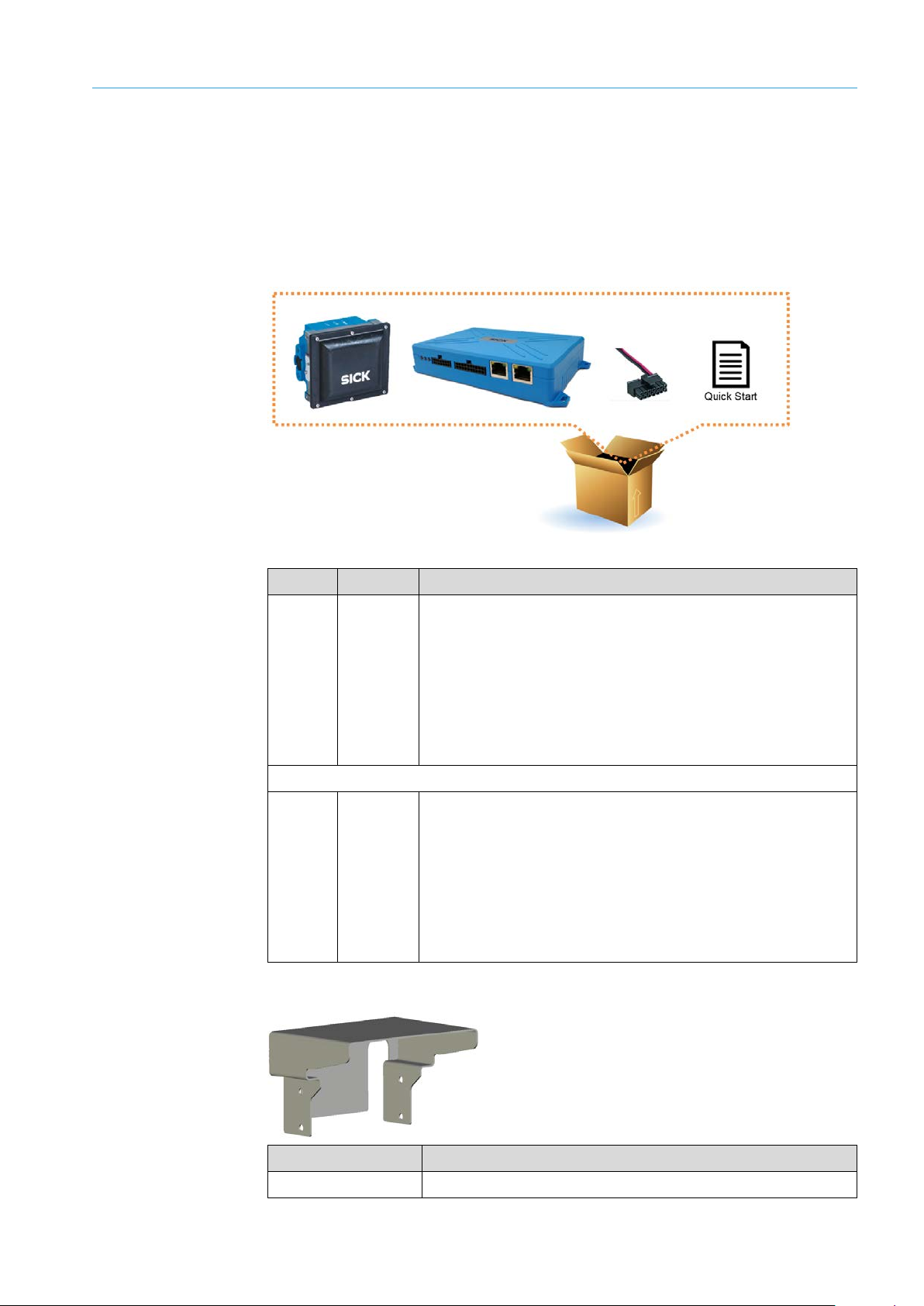
3.1 Scope of delivery
NOTE!
After delivery, inspect the system for transport damage and report any such damage
▸
immediately.
Check that the delivery includes all components listed on the delivery note.
▸
SYSTEM DESCRIPTION 3
Fig. 1: AOS301-WWD scope of delivery
Number Part no. Description
1 1093864 1 AOS301-WWD object detection system consisting of:
• TDC-E200R2
• RMS3xx radar sensor
• 2-pin cable for voltage supply of the TDC-E
• Quick Start guide including download link for the operating
instructions, system documentation, and interface
descriptions
OR
1 1093865 1 AOS301-WWD object detection system consisting of:
• TDC-E200R6
• RMS3xx radar sensor
• 2-pin cable for voltage supply of the TDC-E
• Quick Start guide including download link for the operating
instructions, system documentation, and interface
descriptions
Table 2: AOS301-WWD scope of delivery
Weather hood
Part no. Description
2095958 Weather hood for RMS3xx
Page 12

3 SYSTEM DESCRIPTION
12
8023732/2018-09-10|SIC K
ORIGINAL OPERA TING INSTRUCT IONS | AOS301-WWD
Subject to change without notice
Mounting accessories
Fig. 2: Mounting accessories
No. Part no. Description
1 2095955 Holding bracket for mounting the RMS3xx to poles, etc.
2 2095957 Wall holder for mounting the RMS3xx to walls.
3 6069266 DIN rail bracket for mounting the TDC-E on DIN rail brackets
Table 3: Mounting accessories
Cable accessories
Fig. 3: Cable accessories
No. Part no. Description
1 6068473 2-pin cable for voltage supply of the TDC-E
2 6068472 14-pin Microfit male connector with 14 color-coded open-ended
wires for connecting:
• Voltage supply (2 wires)
• Digital inputs and outputs
• Analog inputs
3
6036159
6042565
6042564
4
6034415
6030928
6036158
6045311
Table 4: Cable accessories
Cable for connecting the RMs3xx to the voltage supply
(M12 connection, open end)
5 m
10 m
20 m
Cable for connecting the RMS3xx to the TDC-E
(M12 connection, RJ45)
5 m
10 m
20 m
30 m
Page 13

SYSTEM DESCRIPTION 3
13
8023732/2018-09-10|SIC K
Subject to change without notice
ORIGINAL OPERA TING INSTRUCT IONS | AOS301-WWD
Replacement devices
Part no. Description
6067896 TDC-E200R2
6067536 TDC-E200R6
1083661 RMS3xx
6068463 GSM antenna
6068474 WLAN/WPAN antenna
Table 5: Replacement devices
Page 14
3 SYSTEM DESCRIPTION
14
8023732/2018-09-10|SIC K
ORIGINAL OPERA TING INSTRUCT IONS | AOS301-WWD
Subject to change without notice
3.2 System components
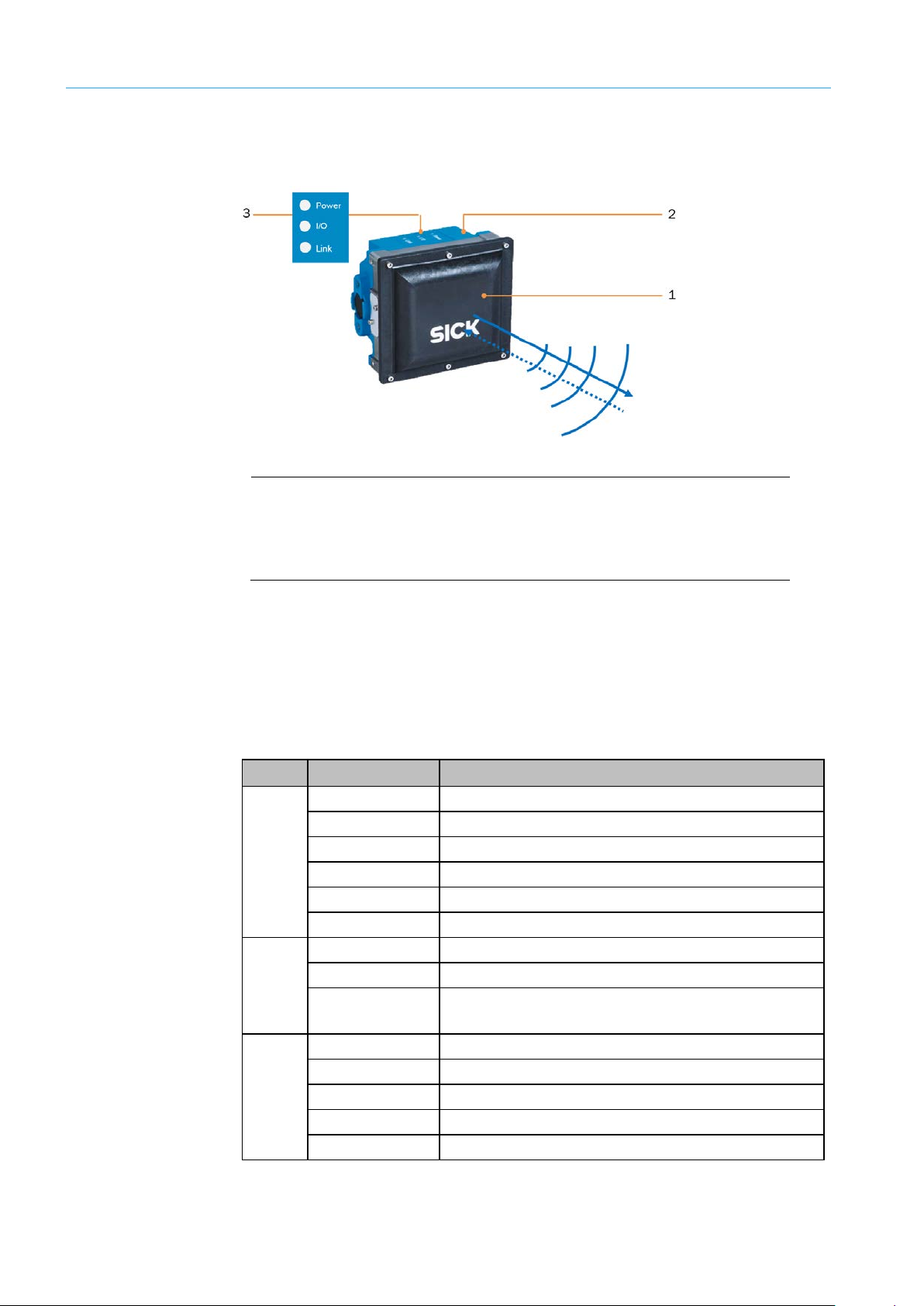
3.2.1 RMS3xx radar sensor
Fig. 4: RMS3xx radar sensor
Legend
1 Radar antenna (front end)
2 Control unit for sending signals to TDC-E
3 Status indicators
Properties
Status indicators
• The RMS3xx radar sensor consists of a radar antenna and a control unit.
• The radar sensor transmits electromagnetic waves.
• If these hit a moving object in the field of view of the radar sensor, the radar waves are
reflected back to the sensor.
• The control unit processes the received radar signals and passes all measured values
on to the TDC-E.
LED Color Meaning
Off Device is switched off.
Yellow Device is starting up.
Green Device is ready for use.
Power
Red (flashing) Device error.
Pink (flashing) Device update is running.
Green (flashing) Device update is complete.
Green No object detected in the field of view.
I/O
Yellow Object detected in the field of view
Red Warning field interrupted. The field interruption is not
used in the AOS301-WWD.
Off No Ethernet connection is present.
Green Ethernet connection is established.
Link
Green (flashing) Data transmission via Ethernet.
Yellow CAN connection is established.
Yellow (flashing) Data transmission via CAN bus.
Table 6: RMS3xx status indicators
Page 15
15
8023732/2018-09-10|SIC K
Subject to change without notice
ORIGINAL OPERA TING INSTRUCT IONS | AOS301-WWD
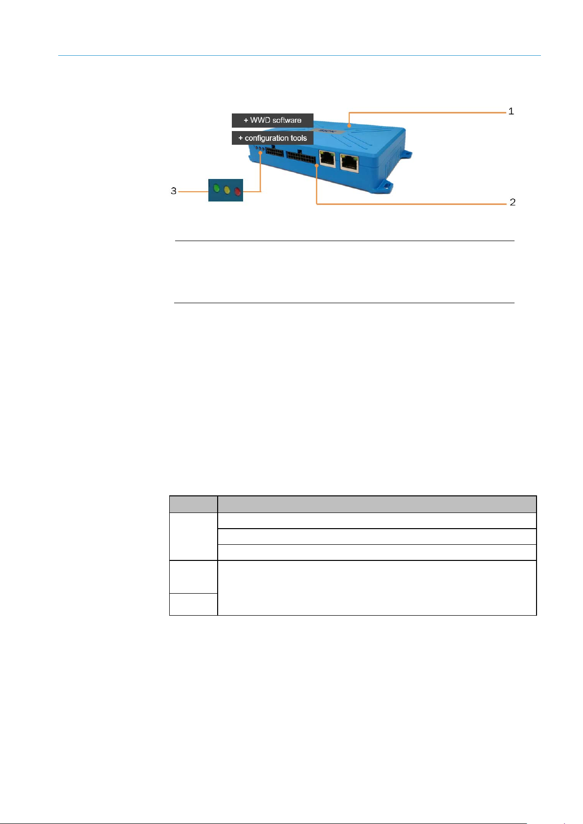
3.2.2 TDC-E200xx telematic data collector
Fig. 5: TDC-E200 telematic data collector
Legend
1 TDC-E with WWD software (TEMS recorder)
2 Interfaces
3 Status indicators
Properties
• The TDC-E with pre-installed WWD software (TEMS recorder) is the control unit of the
AOS301-WWD object detection system.
• The TDC-E receives all measured values received by the RMS3xx radar sensor,
evaluates them for a defined monitoring area (region of interest) and, using this data,
determines the speed and direction of movement of the detected object.
• Vehicles which move in the opposite direction are signaled to the connected customer
system via I/O interface.
• The TDC-E also supports transmission of measurement data as MQTT messages via
Ethernet or wireless networks.
• Tools pre-installed on the device at the factory enable commissioning based on a web-
based interface and system extensions.
SYSTEM DESCRIPTION 3
Status indicators
LED Meaning
Permanently OFF: The device is switched off.
Green
Permanently ON: The device is switched on but has not been booted up.
Intermittently flashing: The device has been successfully booted up.
Yellow
The yellow and red LEDs can be configured in the TDC-E Device Manager.
The modes available in the current version are ON, OFF, and HEARTBEAT
Red
Table 7: TDC-E200 status indicators
(= FLASHING).
Page 16

3 SYSTEM DESCRIPTION
16
8023732/2018-09-10|SIC K
ORIGINAL OPERA TING INSTRUCT IONS | AOS301-WWD
Subject to change without notice
3.3 Operating principle
3.3.1 Vehicle detection and evaluation
The radar sensor is mounted on a vibration-free pole, gallows or portal. Radar waves emit
in the direction of travel, therefore opposite the wrong-way driver (see also chapter 3.4
Project planning).
Fig. 6: Vehicle detection with radar waves
Field of view and
monitored area
Fig. 7: Field of view and monitored area
Legend
1 Field of view of the radar sensor
2 Defined monitoring area
• A monitored area (region of interest) is defined in the field of view of the radar sensor.
The monitored area must be completely inside the field of view of the sensor.
• The monitored area determines which radar measurement points must be taken into
account by the AOS301-WWD. Only those measurement points which are in the defined
monitoring area are evaluated.
Page 17
SYSTEM DESCRIPTION 3
17
8023732/2018-09-10|SIC K
Subject to change without notice
ORIGINAL OPERA TING INSTRUCT IONS | AOS301-WWD
Vehicle detection
Data processing
• As soon as the radar sensor detects an object in the field of view, the positions of the
returned radar signals are forwarded to the TDC-E.
• In the first step, all object positions are discarded which are outside the defined
monitoring area.
• Only measurement points within the monitored area are evaluated.
• The object positions within the monitored area are tracked.
• Vehicle tracking begins as soon as the first measurement point can be assigned to the
monitored area and ends with the first measurement point outside of the monitored
area.
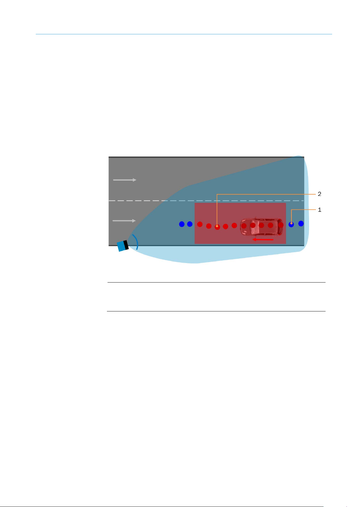
All object positions inside the monitored area are output as trajectories.
Fig. 8: Data processing – object points of the vehicle trajectory
Legend
1 Measurement points in the field of view of the radar sensor
2 Measurement points in the monitored area
• Every object point of the trajectory has a time stamp, the exact position of the
coordinate system and the speed.
• In the last step, the expected direction of travel is compared with the actual direction of
travel based on the object trajectory.
• The actual direction of movement of the vehicle is output as the result.
Page 18
3 SYSTEM DESCRIPTION
18
8023732/2018-09-10|SIC K
ORIGINAL OPERA TING INSTRUCT IONS | AOS301-WWD
Subject to change without notice
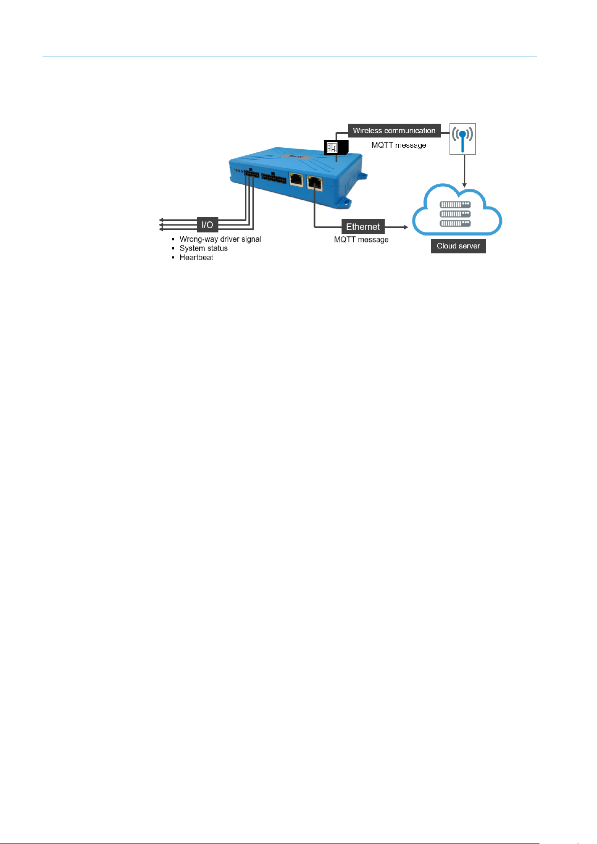
3.3.2 Data output and interfaces
The data is delivered via different optional interfaces.
Fig. 9: Data output and interfaces
I/O
MQTT message
Ethernet/
Wireless network
• If movement is recorded in the opposite direction of movement for a vehicle, a wrong-
way driver signal is output to the customer system via the digital interface of the TDC-E.
• Signaling via the I/O interface allows for quick response time.
• This requires corresponding infrastructure at the measurement site (cables, lights,
etc.).
• The system status and proper functioning of the system (heartbeat) can be signaled
using other digital contacts.
NOTE! Additional information can be found in chapter 6.5.1 Configuring I/O interface
(TDC-E IO plug-in).
• In addition, data of the AOS301-WWD can be called up using MQTT messages via an
MQTT message broker.
• The structure of the MQTT messages can be configured.
• MQTT messages can contain both information on the system status as well as the
measurement data of an object (such as the object positions of the created trajectory
with time stamp and speed and direction of movement).
NOTE! Additional information can be found in chapter 6.5.2 Configuring call-up of MQTT
messages.
• MQTT messages can be called up via the Ethernet interface of the TDC-E or a wireless
network. Calling up via a wireless network makes sense if no cables are laid at the
measurement site.
• The data can be used for analysis purposes and long-term observations, but also for
alarms (with a data connection of appropriate quality).
NOTE! Data transmission via wireless networks requires a SIM card of the country-specific
telecommunications provider (see chapter 4.2.3 Inserting SIM card). The connection
settings are saved in the TDC-E Device Manager (see chapter 6.8.4 Configuring wireless
settings).
Page 19

19
8023732/2018-09-10|SIC K
Subject to change without notice
ORIGINAL OPERA TING INSTRUCT IONS | AOS301-WWD
3.4 Project planning
SYSTEM DESCRIPTION 3
General system
requirements
Vehicles
Measurement location
Mounting position
Coordinate system
• Supply voltage 24 V DC (9 V DC ... 36 V DC) for the RMX3xx and TDC-E.
• I/O cable for processing the wrong-way driver signal by the customer system.
• An Ethernet cable for calling up MQTT messages (optional).
• Object detection at speeds of 10 km/h to 140 km/h.
• Straight and level passage.
• Monitoring of a maximum of two lanes.
Fig. 10: Radar sensor mounting position
• Radar sensor mounting on a vibration-free pole, gallows or a portal. Radar waves
emit in the direction of travel, therefore opposite the wrong-way driver.
• Mounting height 2.5 to 5 m.
The radar sensor is positioned in a three-dimensional coordinate system.
Fig. 11: Coordinate system
• The horizontal axis (X-axis) points orthogonally across the lane.
• The vertical axis (Y-axis) points upward perpendicular to the road surface.
• The movement axis (Z-axis) points in the direction of travel.
NOTE! The zero point in the road coordination system of the AOS301-WWD is always
located on the outer edge of the lane at the height of the ground.
Page 20
3 SYSTEM DESCRIPTION
20
8023732/2018-09-10|SIC K
ORIGINAL OPERA TING INSTRUCT IONS | AOS301-WWD
Subject to change without notice
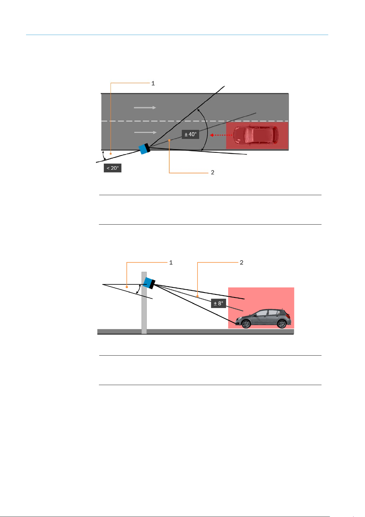
Alignment
The field of view of the RMS3xx is determined by the horizontal direction angle (± 40°),
the height aperture angle (± 8°) and the maximum scanning range of 40 m at 10 m
effective echo area (typical for cars).
Fig. 12: Alignment of RMS3xx – horizontal aperture angle and pivoting angle
Legend
1 Pivoting angle
2 Horizontal aperture angle
Align radar sensor toward the expected direction of travel
▸
The pivoting angle must not deviate from this direction by more than 20°.
▸
2
Fig. 13: Alignment of RMS3xx – height aperture angle and tilt angle
Legend
1 Tilt angle
2 Height aperture angle
Consider a height aperture angle of ± 8° when defining the monitored area.
▸
Select the optimal tilt angle depending on the mounting height of the RMS3xx. Low-
▸
hanging radar sensors have a flatter view than high-hanging ones. This means the
horizontal field of view is particularly large exactly where the vehicles to be detected
are moving.
Page 21

SYSTEM DESCRIPTION 3
21
8023732/2018-09-10|SIC K
Subject to change without notice
ORIGINAL OPERA TING INSTRUCT IONS | AOS301-WWD
Monitored area
The monitored area is placed in the field of view of the radar sensor and defined in the
TEMS Manager via a series of points (see 6.4.4 Configuring monitored area (AOS RMS
system function)). A point is determined by its coordinates on the road.
Fig. 14: Monitored area project planning
Consider the aperture angle, mounting position and maximum scanning range of the
▸
radar sensor.
Design the monitored area so that a vehicle with the maximum expected speed is in
▸
the monitored area for at least 500 ms.
A vehicle with a speed of 40 m/s for example needs a monitored area of 20 m to be
clearly detected.
Page 22

3 SYSTEM DESCRIPTION
22
8023732/2018-09-10|SIC K
ORIGINAL OPERA TING INSTRUCT IONS | AOS301-WWD
Subject to change without notice
3.5 System extension with tools and customer-specific applications
Fig. 15: TDC-E with container docker technology
Docker technology
• The Linux operating system that has been pre-installed on the TDC-E is based on a
powerful ARM processor and utilizes Docker container technology.
• Docker is a tool that makes it easier to create, deploy, and execute applications by
using containers. A container does not just hold the application itself but also all of the
resources required by the application during runtime.
• Thanks to the container technology, the AOS301-WWD can be rapidly extended by
adding customer-specific applications.
• To this end, the application is loaded into a container as a compiled image file and
executed immediately.
NOTE! For more information, please see the operating instructions for the TDC-E.
Page 23
23
8023732/2018-09-10|SIC K
Subject to change without notice
ORIGINAL OPERA TING INSTRUCT IONS | AOS301-WWD
4 Mounting
All transport, assembly, mounting, and electrical installation work must only be carried
out by qualified persons.
• Qualified persons have the specialist training, skills, and experience, as well as
knowledge of the relevant regulations and standards, to be able to perform work
assigned to them and to identify and avoid any potential dangers independently.
• Electricians have the professional training, skills and experience, and knowledge of
the relevant standards and provisions to work on electrical systems and to detect
and avoid any potential dangers independently.
4.1 Mounting the RMS3xx
According to the project planning, the radar sensor is mounted to a portal or to the side of
a gallows or a pole (see chapter 3.4 Project planning).
NOTE! Mount radar sensor so it is electrically insulated from conductive structures to
▸
protect against lightning damage.
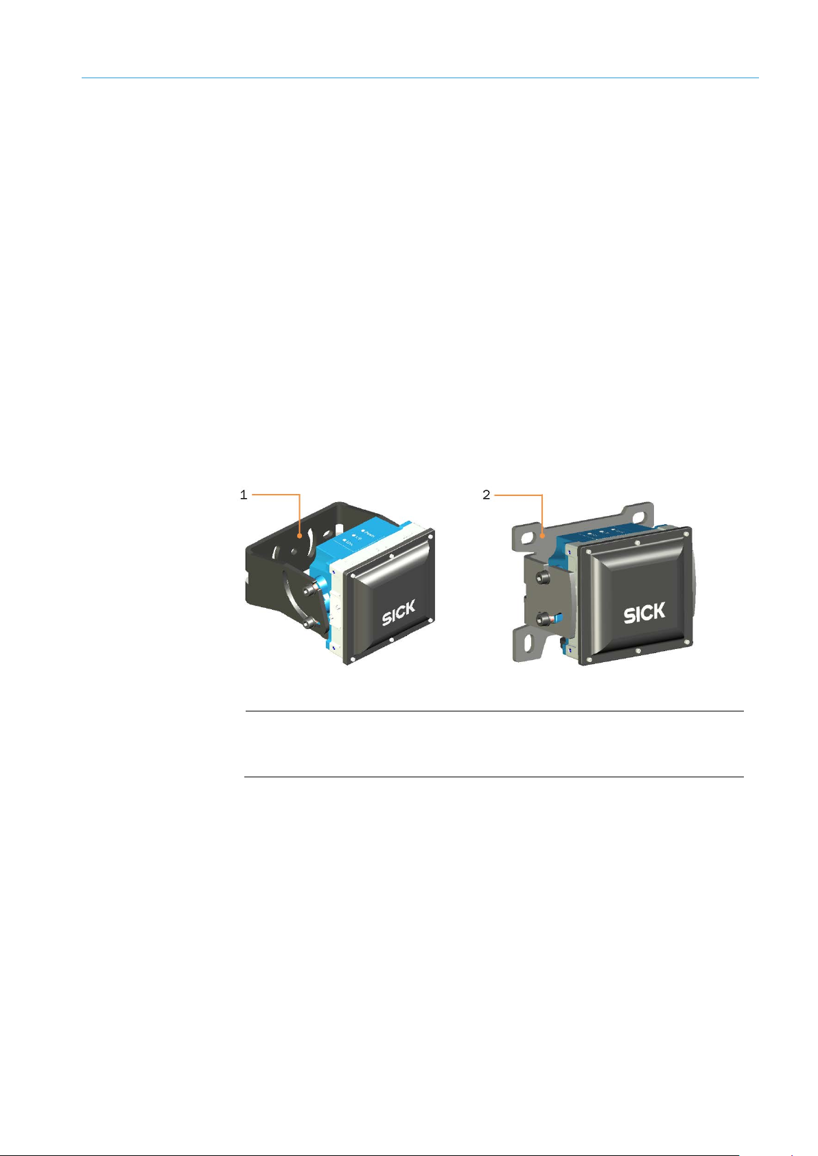
A holding bracket or wall holder is available as an accessory.
MOUNTING 4
Fig. 16: Brackets for mounting the RMS3xx
Legend
1 Holding bracket
2 Wall holder
Page 24
4 MOUNTING
24
8023732/2018-09-10|SIC K
ORIGINAL OPERA TING INSTRUCT IONS | AOS301-WWD
Subject to change without notice
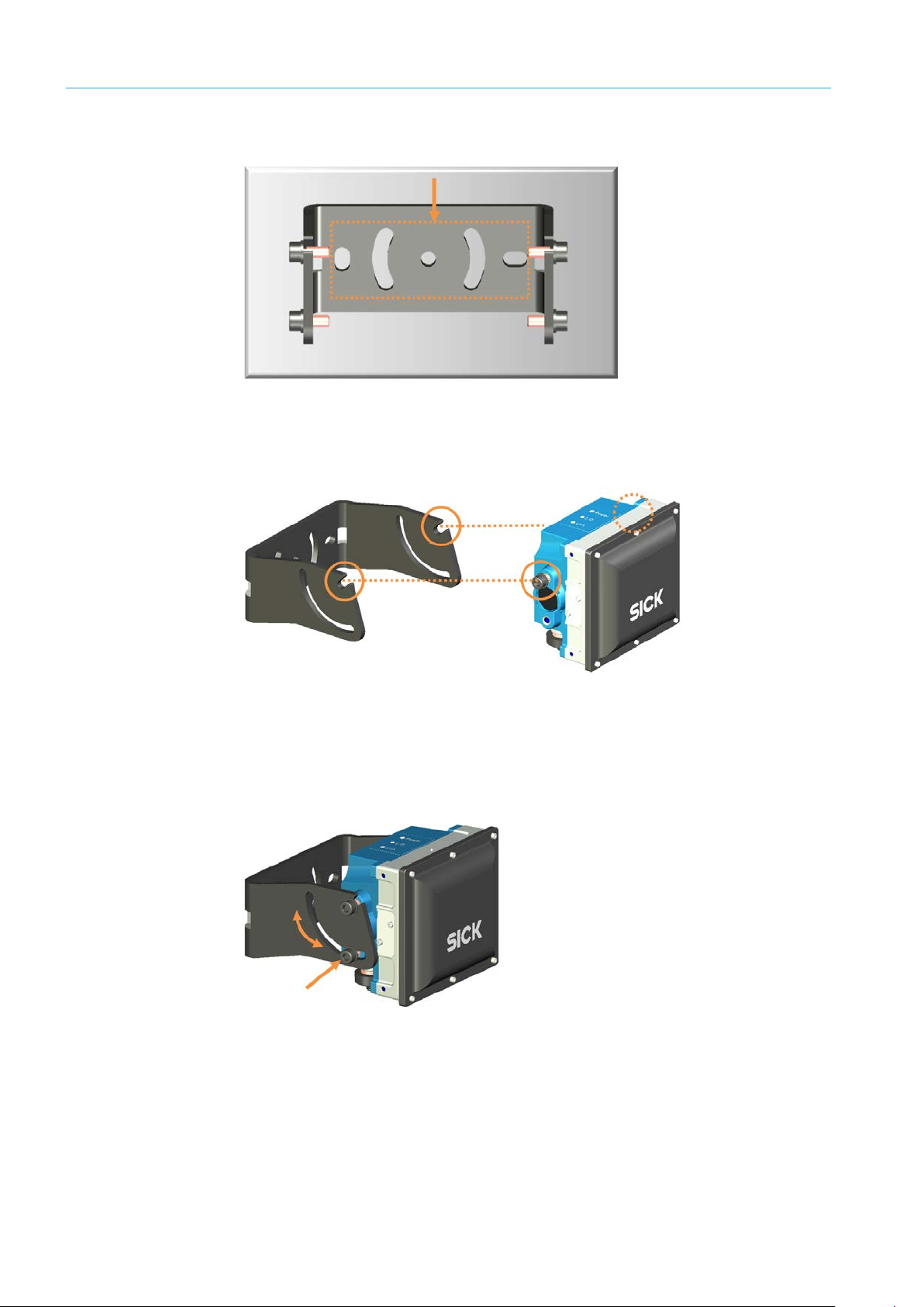
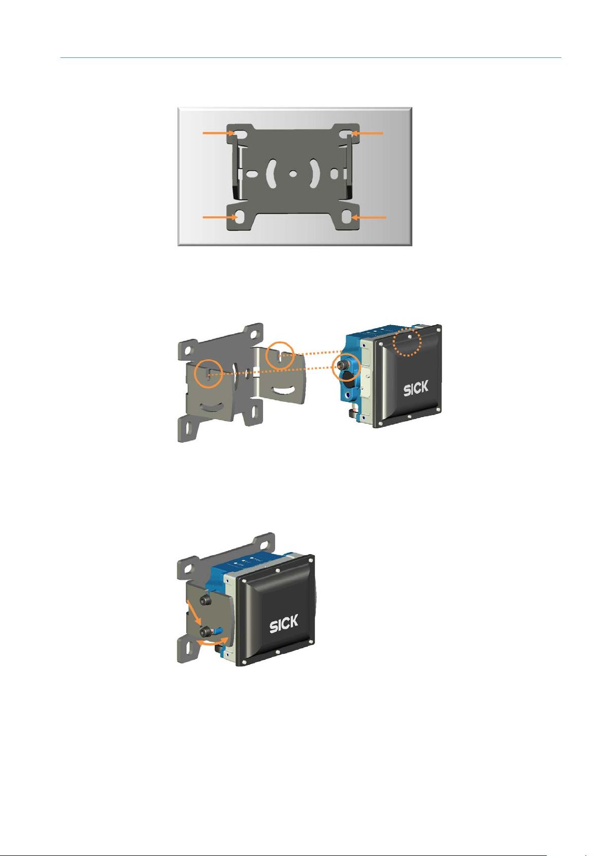
4.1.1 Mounting with holding bracket
Mounting holding
bracket
Fig. 17: Mounting holding bracket on a wall or panel
Mount holding bracket on a wall or a panel.
▸
Installing radar sensor
Fig. 18: Inserting radar sensor into mounting bracket
Screw cylinder screws into the upper thread on both sides as shown.
▸
Insert the radar sensor into the notches of the holding bracket with the screws.
▸
Slightly tighten screws.
▸
Fig. 19: Aligning and fastening radar sensor into the holding bracket
Align radar sensor and fasten it in the holding bracket with two more cylinder screws.
Page 25
25
8023732/2018-09-10|SIC K
Subject to change without notice
ORIGINAL OPERA TING INSTRUCT IONS | AOS301-WWD
4.1.2 Mounting via wall holder
Mounting wall holder
Fig. 20: Mounting wall holder to wall
Mount the wall holder to the wall with four screws.
▸
Installing radar sensor
MOUNTING 4
Fig. 21: Inserting radar sensor into wall holder
Screw cylinder screws into the upper thread on both sides as shown.
▸
Insert the radar sensor into the notches of the wall holder with the screws.
▸
Slightly tighten screws.
▸
Fig. 22: Aligning and fastening radar sensor in wall holder
Align radar sensor and fasten it in the wall holder with two more cylinder screws.
Page 26
4 MOUNTING
26
8023732/2018-09-10|SIC K
ORIGINAL OPERA TING INSTRUCT IONS | AOS301-WWD
Subject to change without notice
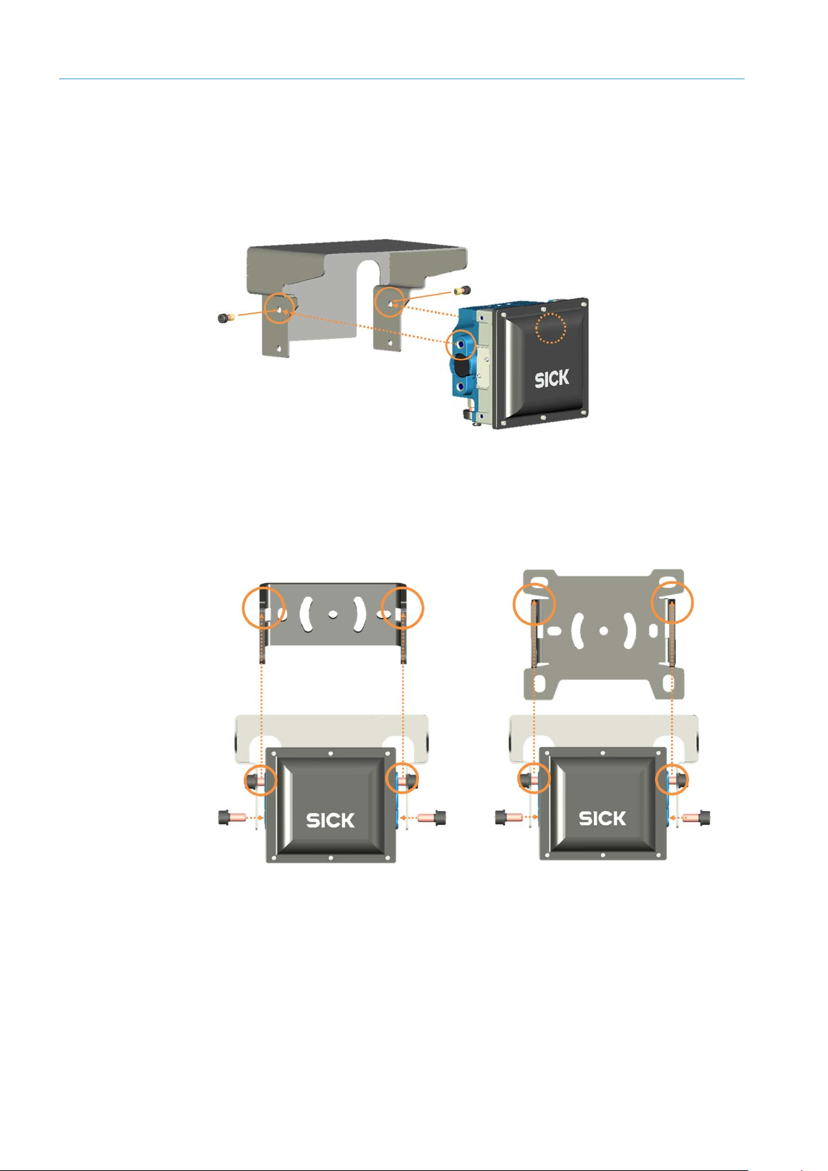
4.1.3 Mounting with weather protection hood
The weather hood fits on both fastening types.
Mounting bracket
Mounting radar sensor
to the weather hood
Mount the holding bracket or wall holder as described.
▸
Fig. 23: Mounting radar sensor to weather hood
Stick cylinder screws through the upper holes on both sides as shown and insert into
▸
the upper thread of the radar sensor.
Only slightly screw in the screws.
▸
Mounting radar sensor
Fig. 24: Mounting radar sensor with weather hood to bracket
Insert the radar sensor with mounted weather hood into the notches of the bracket
▸
with the screws.
Align radar sensor and fasten it in the bracket with two more cylinder screws.
Page 27
27
8023732/2018-09-10|SIC K
Subject to change without notice
ORIGINAL OPERA TING INSTRUCT IONS | AOS301-WWD
4.2 Mounting TDC-E
Ideally, the TDC-E should be mounted at a suitable place in the control cabinet of the
measurement site near the higher-level control but never in the vicinity of transformers or
other power units.
NOTE! Take lightning protection measures for all in- and outgoing connections of the
▸
control cabinet.
4.2.1 Mounting on a plate
MOUNTING 4
Fig. 25: Mounting TDC-E on a plate
Use the mounting holes on the bottom of the device to mount it.
▸
Securely attach the device using four M3 fillister head screws.
▸
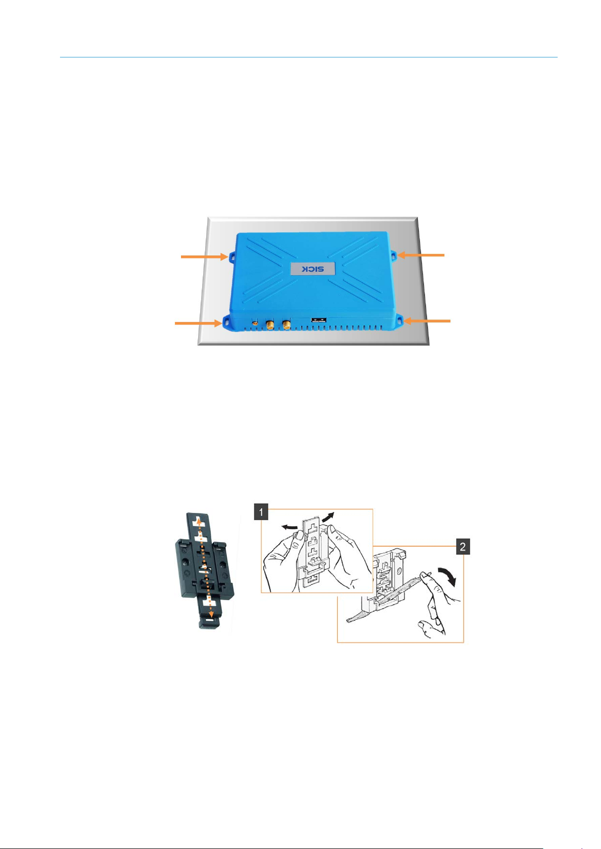
4.2.2 Mounting on DIN mounting rails
A mounting rail bracket is available as an accessory for mounting the TDC-E on DIN
mounting rails.
Adjusting the mounting
rail bracket to the
housing dimensions
Fig. 26: Adjusting the mounting rail bracket to the housing dimensions
Move the bar of the mounting rail bracket into the appropriate position and click it into
▸
place.
While clicking the bar out of one position and into another, gently bend the top section
▸
of the base with your hands.
At the same time, push the actuating bar forward. This will avoid damaging the lug in
the bar guide.
Page 28
4 MOUNTING
28
8023732/2018-09-10|SIC K
ORIGINAL OPERA TING INSTRUCT IONS | AOS301-WWD
Subject to change without notice
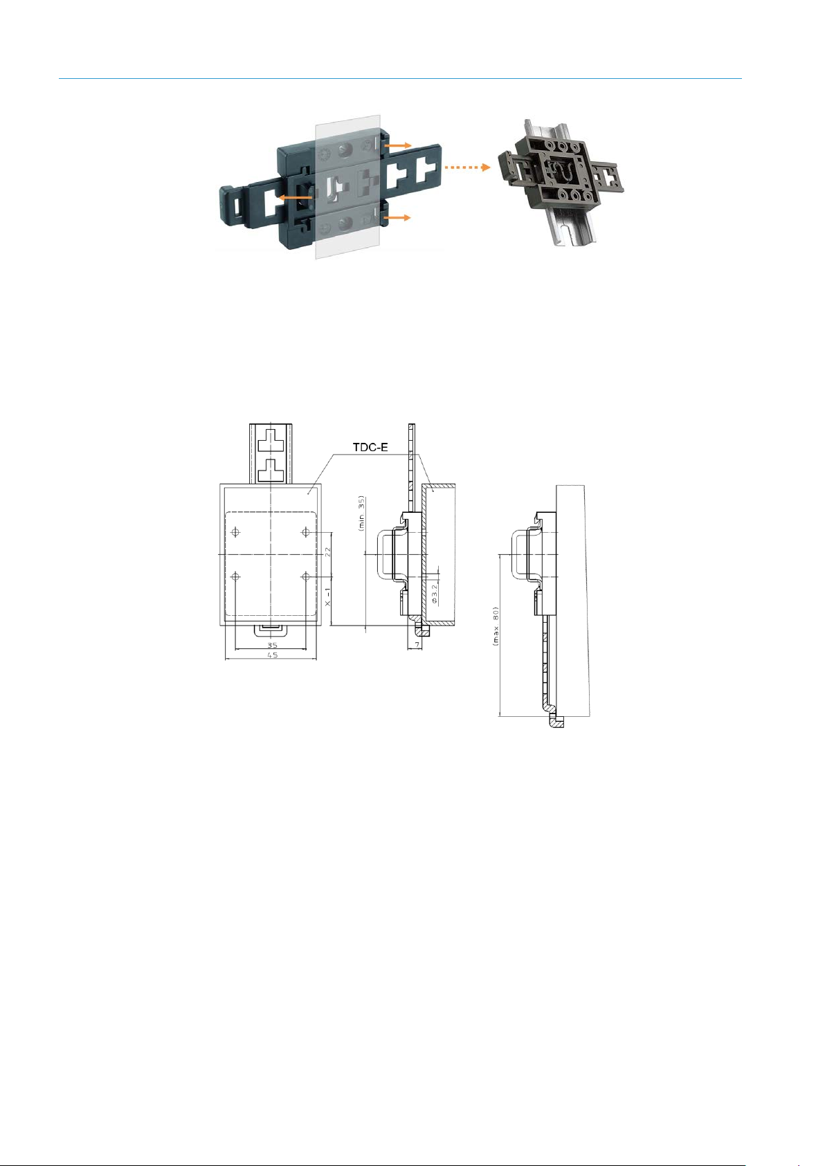
Attaching the mounting
rail bracket to the
mounting rail
Mounting the TDC-E on
the mounting rail
bracket
Fig. 27: Attaching the mounting rail bracket to the mounting rail
Attach the mounting rail bracket to the mounting rail via the lugs, making sure it
▸
audibly engages.
Place the TDC-E on the bar and use the mounting holes on the mounting rail bracket
to screw it on.
Fig. 28: Mounting the TDC-E on the mounting rail bracket
Page 29
29
8023732/2018-09-10|SIC K
Subject to change without notice
ORIGINAL OPERA TING INSTRUCT IONS | AOS301-WWD
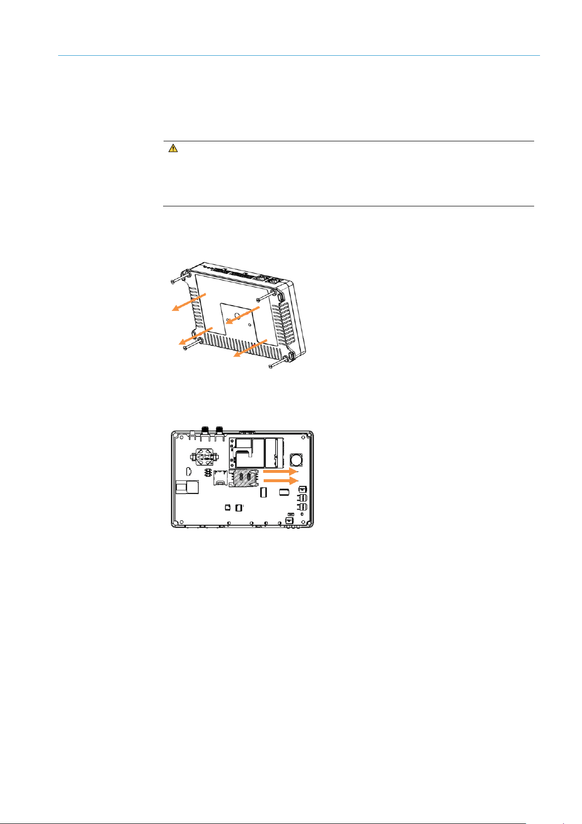
4.2.3 Inserting SIM card
▸
To allow for data transmission via a wireless network, the SIM card of a telecommunications provider must be inserted into the TDC-E.
WARNING!
RISK OF DAMAGE
Use only M2M SIM cards.
▸
Only insert the SIM card when the device is switched off.
Make sure that the device is switched off.
▸
Unscrew the plastic cover on the bottom of the device and remove it.
▸
MOUNTING 4
Slide the plastic cover of the SIM card holder to one side. There is an indicator arrow on
▸
the holder.
Remove the factory-installed SIM card for EU operation.
▸
Page 30

4 MOUNTING
30
8023732/2018-09-10|SIC K
ORIGINAL OPERA TING INSTRUCT IONS | AOS301-WWD
Subject to change without notice
Insert the SIM card from your telecommunications provider into the card holder with
▸
the contacts facing down.
Slide the plastic SIM cover back into place and lock it.
▸
Reattach the housing cover to the bottom of the device and screw it tight.
Note:
Set up APN in TDC-E Device Manager (for more, see chapter 6.8.4 Configuring wireless
▸
settings).
Page 31

31
8023732/2018-09-10|SIC K
Subject to change without notice
ORIGINAL OPERA TING INSTRUCT IONS | AOS301-WWD
5 Electrical installation
All electrical work may only be performed by qualified persons.
• Qualified persons have the specialist training, skills, and experience, as well as
knowledge of the relevant regulations and standards, to be able to perform work
assigned to them and to identify and avoid any potential dangers independently.
• Electricians have the professional training, skills and experience, and knowledge of
the relevant standards and provisions to work on electrical systems and to detect and
avoid any potential dangers independently.
DANGER!
HAZARDOUS ELECTRICAL VOLTAGE
The system is supplied with mains voltage. Risk of electric shocks. Contact causes
death, burns or shock.
Only qualified specialist personnel may conduct electrical work on the system.
▸
Interrupt the voltage supply.
▸
Check residual voltage on the system components.
▸
Pay extra attention.
▸
Always connect equipotential bonding (earthing).
▸
Do not disconnect or remove protective conductor.
▸
The power supply must be disconnected when attaching or detaching electrical
▸
connections.
ELECTRICAL INSTALLATION 5
5.1 Connection overview
Fig. 29: Connection overview
Page 32

5 ELECTRICAL INSTALLATION
32
8023732/2018-09-10|SIC K
ORIGINAL OPERA TING INSTRUCT IONS | AOS301-WWD
Subject to change without notice
PWR
5.2 Connecting the RMS3xx and TDC-E to the voltage supply
The RMS3xx and TDC-E are connected to a separate voltage supply.
Fig. 30: Connection to voltage supply – RMS3xx and TDC-E
Connecting the
RMS3xx
Plug the 5-pin M12 male connector to the Power connection using a suitable cable on
▸
the RMS3xx and tighten the plug connector.
Pin Wire color Connection
1 Brown Voltage supply 9.5 V ... 36 V
TDC-E connection
2 White IN1
3 Blue GND
4 Black OUT1
5 Gray GND IN1/2
Table 8: Connection to the voltage supply – pin assignment RMS3xx
Connect blue and brown wire to the voltage supply.
▸
Non-connected wires must be insulated with a heat-shrinkable sleeve and secured to
▸
prevent electrical connections.
NOTE!
If possible, lay cables inside poles.
▸
Never lay cables so they are hanging.
▸
Use the red and black wires of the connecting cable to connect the TDC-E to the voltage
▸
supply.
Pin Wire color Connection
14 Red VIN (9 V–36 V voltage supply)
7 Black GND for voltage supply
Table 9: Connection to voltage supply – TDC-E pin assignment
Page 33

33
8023732/2018-09-10|SIC K
Subject to change without notice
ORIGINAL OPERA TING INSTRUCT IONS | AOS301-WWD
5.3 Connecting radar sensor to TDC-E
The RMS3xx and TDC-E are connected via an Ethernet cable.
Fig. 31: Connecting RMS3xx and TDC-E
Plug the 4-pin M12 male connector to the Ethernet connection using a suitable cable
▸
on the RMS3xx and tighten the plug connector.
ELECTRICAL INSTALLATION 5
Pin Signal Function
1 TD+ Transmit_Data +
2 RD+ Receive_Data +
Table 10: Ethernet cable RMS3xx --> TDC-E – pin assignment
Connect cable to TDC-E with the Eth0 connection using the RJ45 male connector.
▸
NOTE! Take lightning protection measures at the entry to the control cabinet.
▸
NOTE!
If possible, lay cables inside poles.
▸
Never lay cables so they are hanging.
▸
3 TD- Transmit_Data –
4 RD- Receive_Data +
Page 34

5 ELECTRICAL INSTALLATION
34
8023732/2018-09-10|SIC K
ORIGINAL OPERA TING INSTRUCT IONS | AOS301-WWD
Subject to change without notice
5.4 Connecting customer interface
Connect the digital interface of the TDC-E for output of the wrong-way driver message via
I/O signal. Other I/O interfaces can be used to signal the system status and the
Heartbeat.
Connect the Ethernet interface of the TDC-E to call up the measurement data via MQTT
messages. Alternatively, connect the wireless network.
Fig. 32: Connecting customer interface
Ethernet
I/O
Connect the Ethernet cable to the customer system via the Eth1 Ethernet connection.
▸
NOTE! Take lightning protection measures at the outlet of the control cabinet.
▸
Define IP address of the interface in the TDC-E Device Manager (see chapter 6.8.3
▸
Adjusting Ethernet interface for data output).
Wrong-way driver signal, system status and Heartbeat are each output via a separate
digital output.
Plug the Microfit male connector at the end of the optional connecting cable into the
▸
14-pin female connector on the TDC-E.
Connect the TDC-E to the customer system using one of the following wires of the
▸
14-pin Micro-Fit male connector.
NOTE! Take lightning protection measures at the outlet of the control cabinet.
▸
Pin Wire color Connection
Table 11: Digital interfaces on TDC-E – pin assignment
▸
Wireless
communication
▸
▸
13 Yellow DIO_A
6 White DIO_B
12 Blue DIO_C
5 Pink DIO_D
11 Gray DIO_E
4 Violet DIO_F
Activate interfaces via the TEMS Manager and configure them as outputs (for more,
see chapter 6.5.1 Configuring I/O interface (TDC-E IO plug-in)).
Activate and configure connection settings of the SIM card in the TDC-E Device
Manager (for more, see chapter 6.8.4 Configuring wireless settings).
NOTE! Take into account lightning protection when taking an antenna from the control
cabinet.
Page 35

35
8023732/2018-09-10|SIC K
Subject to change without notice
ORIGINAL OPERA TING INSTRUCT IONS | AOS301-WWD
6 Commissioning
Commissioning may only be performed by qualified persons.
• Qualified persons have the specialist training, skills, and experience, as well as
knowledge of the relevant regulations and standards, to be able to perform work
assigned to them and to identify and avoid any potential dangers independently.
• Electricians have the professional training, skills and experience, and knowledge of
the relevant standards and provisions to work on electrical systems and to detect
and avoid any potential dangers independently.
6.1 Starting the system
Connect the voltage supply.
▸
All hardware and software components of the system are started up and checked for
operational readiness.
• The TDC-E is delivered with the pre-installed applications. When a cold start is
performed, a device that is still in this original state will be ready for operation after
approx. 120 s.
• When a warm start is performed via TDC-E Device Manager, all applications are shut
down first. The operating system and containers are then restarted.
A warm start takes approx. 180 s.
Check the operational status of the components by looking at the status indicators.
▸
COMMISSIONING 6
Page 36

6 COMMISSIONING
36
8023732/2018-09-10|SIC K
ORIGINAL OPERA TING INSTRUCT IONS | AOS301-WWD
Subject to change without notice
6.2 Preparing the configuration PC
The TDC-E is configured using a PC which is connected to the TDC-E via Ethernet. The
TEMS Manager Web and TDC-E Device Manager configuration tools installed on the TDC-E
are started via Ethernet connection.
The configuration tools contain both a browser-based interface and allow for a convenient
system set-up.
Fig. 33: Connecting the TDC-E device and the configuration PC
On delivery, the two Ethernet interfaces on the TDC-E have the following IP addresses:
Notes
Component Default IP address
Eth0 192.168.0.100
Internal interface for radar sensor.
Eth1 192.168.1.100
Customer interface for data output via Ethernet
configuration interface.
Make sure that the configuration PC is in the number range of the TDC-E.
▸
If necessary, change the IP address of the configuration PC.
▸
Connect the configuration PC to the TDC-E via the Eth1 Ethernet port.
▸
Page 37

37
8023732/2018-09-10|SIC K
Subject to change without notice
ORIGINAL OPERA TING INSTRUCT IONS | AOS301-WWD
6.3 Using TEMS Manager
6.3.1 Starting TEMS Manager
Start the web browser on the configuration PC. This browser must support HTML5 and
▸
WebGL.
Start TEMS Manager Web with the following URL:
▸
http://192.168.1.100:80
As soon as the connection to the TDC-E has been established, the TEMS Manager web
interface opens.
COMMISSIONING 6
6.3.2 Using a configuration file to load standard parameters
The AOS301-WWD standard parameters are delivered in an XML file. The parameters are
imported in TEMS Manager, where they are subsequently adjusted to the measurement
site.
In TEMS Manager, click the icon for Load site configuration and start/edit it.
▸
The authorization must be Authorized user or higher Service.
Click on the User name field, enter Service as user name and log in with the default
▸
password set up for this purpose (for more, see appendix at 9.3 Users and
authorizations).
Page 38

6 COMMISSIONING
38
8023732/2018-09-10|SIC K
ORIGINAL OPERA TING INSTRUCT IONS | AOS301-WWD
Subject to change without notice
Select configuration file and click on Start location configuration.
▸
The configuration is loaded in TEMS Manager.
6.3.3 The user interface
The menu bar contains the main registers of the TEMS Manager. This bar remains visible
in all working contexts.
Page 39

COMMISSIONING 6
39
8023732/2018-09-10|SIC K
Subject to change without notice
ORIGINAL OPERA TING INSTRUCT IONS | AOS301-WWD
Registers
• For users with the Operator and Authorized user authorizations, the Location,
Wrong-Way driver objects, Normal-way driver objects, Logs and Info registers are
available.
• The Settings register is restricted to users with the Service authorization.
Register Meaning
Location Shows the measurement site in a live view.
It also allows displaying and editing the system parameters
and delivers information on the system status.
Wrong-way driver
objects
Displays measurement results of vehicles for which a
movement in the opposite direction of movement has been
detected.
Display is done during operation of the AOS301-WWD.
Normal-way driver
objects
Displays measurement results of vehicles for which a
movement in the current direction of movement has been
detected.
Display is done during operation of the AOS301-WWD.
Settings Contains administrative functions. This allows changing user
passwords or updating the system, for example.
Logs Contains the system log files.
Info Provides information on the TEMS Recorder.
Login information
NOTE!
• Clicking on the program name reloads TEMS Manager with the Location register.
• The menu bar also contains notes on system faults.
Display of the logged-in user and the operating status on the right side of the menu bar.
▸
The user symbol opens a menu with the following functions:
▸
Function Meaning
Resetting page
settings
Sets all display settings (zoom, rotation in 3D displays,
table displays, etc.) back to standard values.
Change users Log out current user and log in another user.
Logout Log out current user.
Page 40

6 COMMISSIONING
40
8023732/2018-09-10|SIC K
ORIGINAL OPERA TING INSTRUCT IONS | AOS301-WWD
Subject to change without notice
Display format on small
screens
The TEMS Manager user interface automatically adjusts to the size of the screen. On a
smartphone or tablet, the content is arranged from top to bottom.
Call up registers of the TEMS Manager using the menu icon.
▸
6.3.4 Displaying the measurement site
The Site register is divided into two.
Navigation area
Live view
Legend
1 Live view
2 Navigation area
• Contains system components and system functions with the parameters of the
measurement site, e.g. the system component RMS320 with the radar sensor.
• Data output is configured via plug-ins in the bottom area.
• Visualizes the measurement site along with the system components, their installation
site, and their status display.
• Displays the detected vehicles as 3D models during operation.
• Visualizes all measurement points of the sensor (raw data) as well as the calculated
object points of the vehicle trajectories.
Page 41

COMMISSIONING 6
41
8023732/2018-09-10|SIC K
Subject to change without notice
ORIGINAL OPERA TING INSTRUCT IONS | AOS301-WWD
Rotate
Symbols
Adapting the graphic
display
Symbol Meaning
Load site configuration and start/edit it
• Allows you to load a configuration file.
• You can either start the configuration or open it in editing mode instead.
Stop current site configuration
• Stops the current configuration.
Edit site configuration
• Changes to edit mode.
Activate/deactivate expert mode
• Switches expert mode on or off.
• Expert mode displays all system functions in the navigation area and
functions for editing the parameter values, etc.
Save current site configuration on hard drive
• Saves the current site configuration onto a data card.
Adapting the view of the measurement site with the tools in your browser.
▸
Function Meaning
Rotates the site clockwise or counterclockwise on the GUI when you
press and hold the left mouse button.
Control with hand
movements
Moves the site up, down, right, and left when you press and hold the right
mouse button.
Enlarges or reduces the display of the site via the mouse wheel when the
mouse pointer is on the graphical display.
If you want to increase or decrease the zoom increments, press and hold
the Shift key at the same time.
Table 12: Functions for displaying the measurement site in TEMS Manager
Controlling with hand movements using a computer with touchscreen display.
▸
Function Meaning
Two-finger gestures (zoom in/zoom out)
• Moving the thumb and pointer finger apart zooms in on the graphical
display.
• Pushing the thumb and pointer finger together (pinching) zooms out on
the graphical display.
Rotate
• Press your finger on the graphical display and pull in the desired
direction to make the measurement site rotate accordingly.
Table 13: Controlling the display of the measurement site in TEMS Manager using hand
movements
Page 42

6 COMMISSIONING
42
8023732/2018-09-10|SIC K
ORIGINAL OPERA TING INSTRUCT IONS | AOS301-WWD
Subject to change without notice
6.3.5 Activating expert mode
In expert mode, functions appear which allow system and device parameters and plug-in
settings to be displayed and edited.
In the menu bar, click on the De-/Activate expert mode icon. The icon appears blue if
▸
expert mode is activated.
6.3.6 Displaying system parameters
The system parameters for the relevant system function/system component can be
visualized by opening the detail window.
NOTE! When location configuration is running, it is only possible to display parameters,
not edit them. Change to editing mode for editing (see chapter 6.4.1 Switching to editing
mode).
In the tree, click on the gear icon of a system function or system component
▸
At first, the detail window shows several key parameters (e.g mounting position of the
▸
radar sensor).
Page 43

COMMISSIONING 6
43
8023732/2018-09-10|SIC K
Subject to change without notice
ORIGINAL OPERA TING INSTRUCT IONS | AOS301-WWD
Displaying all
parameters
Displaying the device
status
Click on the Parameter link. The number of displayed parameters depends on the
▸
authorizations of the logged-in user.
Click on the Status link.
▸
Read off status information on the system component.
▸
Page 44

6 COMMISSIONING
44
8023732/2018-09-10|SIC K
ORIGINAL OPERA TING INSTRUCT IONS | AOS301-WWD
Subject to change without notice
6.3.7 Visualizing radar measurement points and monitored area in the live view
In the live view, the measurement values recorded in the field of view of the radar sensor
as well as the tracked object positions in the monitored area can be hidden during
configuration.
Go to the device level in the navigation area and click the Visualize live data for device
▸
RMS 320
icon. The functions for visualizing the measurement points in the live view appear.
Display the measurement points of the radar sensor in the field of view with (Raw)
▸
targets.
AOS Rms
Display the tracked object points in the monitored area with Objects.
▸
In the navigation area on the level of the AOS Rms system function, click on the
▸
Inspect live data of the component. The functions for visualizing the monitored area
appear.
With Region of interest, display the geometry of the monitored area (for more, see
▸
chapter 6.4.4 Configuring monitored area (AOS RMS system function).
Click on the folded-down function again to hide the measurement points and monitored
area.
Page 45

45
8023732/2018-09-10|SIC K
Subject to change without notice
ORIGINAL OPERA TING INSTRUCT IONS | AOS301-WWD
6.4 Adapting system parameters in TEMS Manager
6.4.1 Switching to editing mode
The standard parameters are adjusted to the measurement site in edit mode.
Click on the Edit location configuration icon in the menu bar.
▸
NOTE! A user with the Authorized user or Service authorizations must be logged in to
switch (for more, see appendix at 9.3 Users and authorizations).
Work through the hierarchical structure of the navigation tree from top to bottom when
▸
editing the system parameters.
NOTES ON LINKS
Do not change the links to other system functions that have been set up using the
chain-link icon
.
COMMISSIONING 6
Symbols
The toolbar above the navigation tree offers the following functions:
Symbol Meaning
Load site configuration and start/edit it
• Allows you to load a configuration file.
• You can either start the configuration or open it in editing mode instead.
Start current site configuration
• Starts the configuration that is currently open in editing mode.
• A red number in the icon indicates that the configuration is erroneous.
Erroneous configurations cannot be started.
Page 46

6 COMMISSIONING
46
8023732/2018-09-10|SIC K
ORIGINAL OPERA TING INSTRUCT IONS | AOS301-WWD
Subject to change without notice
Symbol Meaning
Edit site configuration
• To quit editing mode, click the blue icon. The configuration remains
loaded.
• To reopen the configuration file in editing mode, click the icon again.
• Click the
Activate/deactivate expert mode
Switches expert mode on or off.
Expert mode displays all system functions in the navigation area and
functions for editing the parameter values, etc.
Save current site configuration on hard drive.
Saves the current site configuration onto a data card.
• Reset site configuration.
• Resets all the changes that have been made to the system parameters
in editing mode, but only after you confirm the prompt.
• The navigation tree will then be completely blank.
• The icon only appears in expert mode.
icon to restart the loaded configuration file.
6.4.2 Configuring the measurement site
Notes on entering data
Designating the
measurement site
Designating the road
• All the designations underlined in blue can be changed by clicking the relevant
designation.
• An input field then appears so that you can enter the desired text.
In the header, click on the current designation.
▸
Enter name.
▸
Confirm with Enter.
Click the road name underlined in blue in the navigation tree.
▸
Change the designation and confirm with Enter.
▸
Page 47

COMMISSIONING 6
47
8023732/2018-09-10|SIC K
Subject to change without notice
ORIGINAL OPERA TING INSTRUCT IONS | AOS301-WWD
Configuring road
Signing the
configuration
Click the Edit road configuration icon on the road level.
▸
An input line appears underneath the road per lane.
Adjust values underlined in blue.
▸
Define the number of lanes and the lane width to be monitored.
▸
NOTE! The side strip is also counted as a lane in the default settings. It can also be
monitored like the regular lines if the monitored area is set accordingly.
Monitoring the hard shoulder is recommended since wrong-way drivers might very well
drive on these.
Define permitted direction of travel display. With the normal setting, the arrow in the
▸
live view points from the top left to the bottom right.
NOTE! If the road is configured with the existing lanes, the normal-way and wrong-way
drivers are assigned to a lane (see chapter 6.4.5 Defining expected direction of travel
(WWD system function)). The display of the direction of travel improves the view in the
live view since it gives the actual status. This particularly helps with configuration since
the real world and its representation in the live view can be better compared. For
example, a quick check can be done to determine whether the radar measurement
points are displayed between lane 1 and 2 as expected.
By applying a signature, you can – for example – document that a particular configuration
has been checked and approved. The signature is encrypted. It is generated when the
configuration is saved and written to the XML configuration file. Among other things, the
signature contains a reference to the configuration PC, the details of the logged-in user,
and the date of saving.
NOTE! A signed configuration cannot be changed without losing the signature. This offers
a reliable way of checking whether the configuration has been changed (e.g., following the
latest standardization procedure).
Page 48

6 COMMISSIONING
48
8023732/2018-09-10|SIC K
ORIGINAL OPERA TING INSTRUCT IONS | AOS301-WWD
Subject to change without notice
Click on the Sign road configuration icon on the road level.
▸
Two input fields appear underneath the road.
Enter person which has released the configuration.
▸
Document the release with a note.
▸
Click on Sign. The signature information is supplemented by a date field. Once the
▸
signature has been applied, the Name, Notes, and Date fields are deactivated and can
no longer be changed.
The Sign road configuration icon turns green.
To hide the signature area, click the Sign road configuration icon again.
▸
Quitting editing mode
6.4.3 Configuring radar sensor (system function RMS320)
Click the Edit road configuration icon.
▸
The enter line in the navigation tree is hidden.
RMS320 system
System function
parameters
function
The RMS320 system function receives and processes all measurement data which is in
the field of view of the radar sensor.
The exact mounting position of the radar sensor in the coordinate system is determined
via the parameters of the RMS320 system function.
NOTE! The network parameters of the radar sensor are specified by loading the
configuration file. Adjustment is not necessary.
Page 49

COMMISSIONING 6
49
8023732/2018-09-10|SIC K
Subject to change without notice
ORIGINAL OPERA TING INSTRUCT IONS | AOS301-WWD
Rough alignment in
live view
Exact mounting
position
Click on the radar sensor in the live view.
▸
Click on the component again and hold the mouse button down. A grid appears to
▸
serve as a guide.
NOTE! The orientation of the grid will automatically adapt to the current perspective
of the live view.
Rotate the measurement site in the live view to switch between displaying the grid
▸
along the X-axis and the Z-axis, respectively.
Then move the component within the desired level.
▸
On the radar sensor level in the navigation tree, click the Edit system component
▸
position icon.
The input lines appear. These already contain the position values defined during rough
alignment.
The position and angle can be defined using either the slide controls or by entering the
▸
values manually.
Adapt the view so that the effects of the entries are clearly visible in the graphic
▸
interface.
NOTE!
Position cursor on a controller and turn the mouse wheel.
▸
The values increase/decrease in “standard” increments.
▸
To increase/decrease the zoom increments, simultaneously press and hold the Shift
▸
key or the Ctrl key, respectively.
Page 50

6 COMMISSIONING
50
8023732/2018-09-10|SIC K
ORIGINAL OPERA TING INSTRUCT IONS | AOS301-WWD
Subject to change without notice
6.4.4 Configuring monitored area (AOS RMS system function)
AOS RMS
system function
System function
parameters
Entering dimensions
The AOS RMS system function processes the measurement points passed on by the
RMS320 system function. All object positions which are outside the defined monitoring
area are thereby discarded. The object positions within the monitored area are tracked.
Vehicle tracking begins as soon as the first measurement point can be assigned to the
monitored area and ends with the first measurement point outside of the monitored area.
All object positions inside the monitored area are output as trajectories by the AOS RMS
system function. Every object point of the trajectory has a time stamp, the exact position
of the coordinate system and the speed.
The geometry of the monitored area is defined by the parameters of the AOS RMS system
function. The monitored area must be completely in the field of view of the sensor.
The dimensions of the monitored area are defined as point sequences. The coordinates of
the individual points are entered separated by a semicolon.
Fig. 34: Entering dimensions of the monitored area
Page 51

COMMISSIONING 6
51
8023732/2018-09-10|SIC K
Subject to change without notice
ORIGINAL OPERA TING INSTRUCT IONS | AOS301-WWD
Click on the Show details icon on the level of the AOS RMS system function.
▸
Enter polygon points separated by a semicolon.
▸
NOTE! If the side strip is to be monitored, it must be taken into account by the polygon.
Object tracking is set by default.
▸
Click on Save.
▸
NOTE! The geometry of the monitored area can be displayed in the live view (for more, see
chapter 6.3.7 Visualizing radar measurement points and monitored area in the live view).
Page 52

6 COMMISSIONING
52
8023732/2018-09-10|SIC K
ORIGINAL OPERA TING INSTRUCT IONS | AOS301-WWD
Subject to change without notice
6.4.5 Defining expected direction of travel (WWD system function)
The WWD system function evaluates the object trajectories received by the AOS RMS
system function. The expected direction of travel is compared with the actual direction of
travel here. The actual direction of movement of the vehicle is output as the result.
System function
parameters
The direction of travel expected in the monitored area is stored via the WWD system
function parameters.
On the level of the WWD system function, click on the Show details icon.
▸
Set the Z-direction to +1 or –1 in the ExpectedDrivingDirectionZ parameter.
▸
The Z-direction corresponds to the Z-direction of the road coordinate system as shown
in the live view.
NOTE! The expected direction of travel is not related to a lane, but to the defined
monitoring area. The monitored area can be placed regardless of the lanes and can
therefore be outside lanes or cross several ones. Since the direction of travel may not
be clear by looking at the lane, it must be specified separately in relation to the road
coordinate system.
Specify minimum and maximum vehicle speed to get a valid wrong-way driver
▸
evaluation. Measurements of vehicles whose speeds are over or under this are
considered invalid.
NOTE! The AOS301-WWD system supports object detection at speeds of 10 km/h to
140 km/h.
Click on Save.
▸
Page 53

53
8023732/2018-09-10|SIC K
Subject to change without notice
ORIGINAL OPERA TING INSTRUCT IONS | AOS301-WWD
6.5 Configuring data output in TEMS Manager
6.5.1 Configuring I/O interface (TDC-E IO plug-in)
The data output is configured in TEMS Manager using plug-ins.
The TDC-E IO plug-in controls the output of the wrong-way driver signal to the customer
system via a digital I/O interface of the TDC-E. The system status and the Heartbeat can
also be output via this plug-in.
The TDC-E IO plug-in is created when the configuration file is loaded.
At the level of the TDC-E IOplug-in, click on theShow details icon.
▸
COMMISSIONING 6
Interfaces
• The TDC-E IO plug-in basically activates all digital interfaces of the TDC-E.
• They are configured in the DIO_A_Direction, DIO_B_Direction etc. parameters, each
as an output (Out). They can also be configured as an input (In).
• The DIO_A_Value, DIO_B_Value etc. parameters belonging to the interface define the
initial state set for the respective output.
If the value of an output is set to True, it is initialized with a high level when the
configuration is started, otherwise with a low level. This value is ignored for interfaces
configured as inputs.
Page 54

6 COMMISSIONING
54
8023732/2018-09-10|SIC K
ORIGINAL OPERA TING INSTRUCT IONS | AOS301-WWD
Subject to change without notice
•
•
•
Rule file
• A rule file determines which digital outputs are addressed by which events.
• The AOS301-WWD system is delivered with the Default Rules for TDC-E I/O Plugin rule
file. This already contains settings for the standard case.
Output Description
DIO_A
The plug-in has been loaded and connection to the TDC-E
hardware manager has been established.
• Static signal.
DIO_B
The configuration is running.
• Static signal.
DIO_C • Wrong-way driver message.
• Pulsating signal in fixed interval.
DIO_E
Normal-way driver message.
• Pulsating signal in fixed interval.
NOTE! If needed, remove, add or change rules in the rule file (see below).
Page 55

55
8023732/2018-09-10|SIC K
Subject to change without notice
ORIGINAL OPERA TING INSTRUCT IONS | AOS301-WWD
Watchdog
Editing rule file
COMMISSIONING 6
In the WatchDogOutput parameter, define the output through which the Heartbeat
▸
signal should be sent out.
In the WatchDogInterval parameter, define the length of time between the on/off
▸
states of the watchdog output.
NOTE! A time space of 0 (ms) deactivates the heartbeat signal.
The rule file can be opened and edited. Existing rules can be changed or additional rules
supplemented. New rule files can also be created and used in the AOS301-WWD.
An example for a useful additional rule is wrong-way driver detection in a tunnel which can
be completely blocked with a traffic light. If the signal of the red traffic light is laid on the
input of the TDC-E, normal-way drivers which cross over the red light can be output as
wrong-way drivers via a digital output.
NOTE! For convenient data editing, log in as a user with the Service authorization
▸
directly in the TEMS Manager.
With Info Files, you can open the list of previously downloaded files.
▸
Page 56

6 COMMISSIONING
56
8023732/2018-09-10|SIC K
ORIGINAL OPERA TING INSTRUCT IONS | AOS301-WWD
Subject to change without notice
▸
▸
▸
▸
Open TdceIoRules-Default rule file using the gear icon for editing
With the Service authorization, you can edit the contents of the XML file directly in
TEMS Manager (for more, see the appendix at 9.3 Users and authorizations).
Click on Save changes.
Change to the Location register and reload the last loaded location configuration.
Click the Edit location configuration icon. The site configuration is opened in edit
mode.
Page 57

57
8023732/2018-09-10|SIC K
Subject to change without notice
ORIGINAL OPERA TING INSTRUCT IONS | AOS301-WWD
6.5.2 Configuring call-up of MQTT messages
The MQTT plug-in can be used to call up information on the system status as well as
measurement data of the recorded vehicles (such as the object positions of the created
trajectory with time stamp and speed and direction of movement) via MQTT messages.
The MQTT messages must be configured accordingly.
Publish/
Subscribe principle
Fig. 35: MQTT messages – Publish/Subscribe principle
COMMISSIONING 6
• MQTT is a special client-server messaging log that relies on the publish/subscribe
principle.
• Communication basically takes place via a central distribution list called the MQTT
message broker.
• Each message sent by a client contains a topic with the data. It is the MQTT plug-in that
assumes the publisher role within the AOS301-WWD system.
• Each MQTT client that wishes to receive the messages for the topic must subscribe to
them on the message broker and log in to the MQTT broker.
Page 58

6 COMMISSIONING
58
8023732/2018-09-10|SIC K
ORIGINAL OPERA TING INSTRUCT IONS | AOS301-WWD
Subject to change without notice
Adding “MQTT” plug-in
Click on the Add Plugin link in the navigation area.
▸
NOTE! The link only appears in expert mode (for more, see chapter 6.3.5 Activating
expert mode).
A list of all available plug-ins opens.
▸
Select the MQTT plug-in. The list closes. The MQTT plug-in appears in the navigation
▸
area.
At the level of the MQTT plug-in, click on theShow details icon.
▸
Page 59

COMMISSIONING 6
59
8023732/2018-09-10|SIC K
Subject to change without notice
ORIGINAL OPERA TING INSTRUCT IONS | AOS301-WWD
Loading the
configuration file:
The configuration file determines which data and information are contained in the MQTT
message.
Click on the ConfigFile parameter.
▸
Select one of the supplied configuration files.
▸
Configuration file Description
MQTT Default Config • The RecorderState topic delivers information on the
system status. The information is provided at regular
intervals.
• The Recorded Data topic describes the preparation of
the incoming vehicle data in JSON format. Vehicle data
is provided when a vehicle is measured.
NOTE! The MQTT messages are published for the topics
as soon as a new RecorderState or a new RecordedData
event occurs.
MQTT WWD Base Config • The RecorderState topic delivers information on the
system status.
• The Recorded Data topic delivers the measurement
data of a vehicle with direction of travel, wrong-way
driver status and speed.
MQTT WWD Trajectory
Config
• The RecorderState topic delivers information on the
system status.
• In addition to the measurement data of the basic
configuration, the Recorded Data topic delivers the
object positions of the created trajectories with time
stamp and speed.
Logging into
MQTT server
Configuring topics
Save MQTT access data of the MQTT servers (MQTT message broker).
▸
To do so, enter the IP address and the port of the MQTT server in the Host and Port
▸
fields.
Enter the username and password for logging into the MQTT server.
▸
In the MainTopic parameter, define the topic name under which the MQTT publish
▸
message is sent to the broker. The topic name can be freely selected.
The XML configuration file selected contains other sub-topics per MQTT message with
▸
the system information and vehicle data to be sent.
The structure is as follows:
Page 60

6 COMMISSIONING
60
8023732/2018-09-10|SIC K
ORIGINAL OPERA TING INSTRUCT IONS | AOS301-WWD
Subject to change without notice
You can either subscribe to topics individually or collectively. For example,
MainTopic/# subscribes to everything published in MainTopic or in a topic under it.
Example
Editing the XML file
A realistic structure could look like this:
It is typically not necessary to edit XML configuration files since these are tailored to the
AOS301-WWD object detection system.
If a user-defined XML configuration file is needed, you can create it yourself as when
editing the interface files via data processing (for more, see 6.5.1 Configuring I/O
interface (TDC-E IO plug-in)) The existing files can be used as templates here.
MainTopic/subtopic2 would only receive data published under subtopic2.
Page 61

61
8023732/2018-09-10|SIC K
Subject to change without notice
ORIGINAL OPERA TING INSTRUCT IONS | AOS301-WWD
6.6 Configuring in TEMS Manager
6.6.1 Checking proper measuring operation in TEMS Manager
Click on the Start location configuration icon in the toolbar. The start progress bar
▸
visualizes the progress.
COMMISSIONING 6
Procedure if start fails
Operational readiness
Check proper voltage supply of the system components, network connectivity and
▸
IP address.
Make sure that the radar sensor has been mounted according to the specifications
▸
(see chapter 3.4 Project planning).
Check the position and alignment of the radar sensor in TEMS Manager. The position
▸
and alignment must match the actual conditions.
• After successful configuration start, all system components are shown in green in the
live view.
• In the navigation tree, the operational readiness of the system functions and system
components is indicated by a green square.
Page 62

6 COMMISSIONING
62
8023732/2018-09-10|SIC K
ORIGINAL OPERA TING INSTRUCT IONS | AOS301-WWD
Subject to change without notice
NOTE!
• When configuration starts, the radar sensor remains red until a connection has been
established. Depending on the network connectivity, this may take up to two minutes.
• If the radar sensor remains permanently red, it could be that an incorrect IP address
has been assigned to it. The problem could also be caused by a missing or inadequate
voltage supply or poor network connectivity.
Additional information on fault detection can be found in chapter 8.1 Fault diagnosis in
TEMS Manager.
6.6.2 Save configuration
To be able to resolve fault situations quickly, SICK Support often needs to have the
current configuration file for the measurement site. This file can be saved onto the hard
drive of a computer so that it can be sent to SICK Support.
The computer must be connected to the TDC-E.
Note
Fig. 36: Saving the configuration on the hard drive
NOTE! The site configuration can be stored while a configuration is running. The process
for saving a site configuration does not affect the current system status.
Click the Save current site configuration on hard drive icon in the toolbar.
▸
The download dialog box of the browser opens right away.
▸
Specify storage location for the configuration file. The site configuration is saved in
▸
XML file format.
Page 63

63
8023732/2018-09-10|SIC K
Subject to change without notice
ORIGINAL OPERA TING INSTRUCT IONS | AOS301-WWD
6.7 Checking measurement operation is working properly
A test run after commissioning must make sure that the system components are working
correctly and that they are delivering plausible measurement results.
The test run can only be performed if the site configuration process has been successfully
completed and all of the system functions and system components in the navigation tree
have a green circle next to them.
6.7.1 Displaying vehicles with measured values
Whenever TEMS Manager is connected to the TEMS Recorder, the Normal-way driver
objects and Wrong-way driver objects working ranges contain a table of the last 200
vehicles recorded. These are listed in chronological order.
Among other things, the display shows the time of recording, the direction of travel, the
monitored lane, the number of single measurements and the length and width of the
trajectory.
COMMISSIONING 6
Editing display
Defining the number of vehicles displayed per page
▸
Filter vehicle list via the search field.
▸
Display or hide columns using the tool icon.
▸
Page 64

6 COMMISSIONING
64
8023732/2018-09-10|SIC K
ORIGINAL OPERA TING INSTRUCT IONS | AOS301-WWD
Subject to change without notice
… …
Page numbers
Checking the
measurement results
6.7.2 Accessing detailed information about a vehicle
To switch between the individual pages of the vehicle overview, use the page numbers
▸
on the bottom right-hand side.
Symbol Meaning
Opens the first page.
Opens the last page.
The icon for the currently open page is highlighted in blue.
Click this icon to switch to the previous or next page from the current one.
Allows you to open a specific page directly.
Check that the status of the measurement site is correct using the table display.
▸
Ensure that the vehicles are detected continuously.
▸
Make sure that the AOS301-WWD is delivering plausible measured values.
▸
For each vehicle, you can open a details page.
Click on the vehicle line.
▸
Page 65

COMMISSIONING 6
65
8023732/2018-09-10|SIC K
Subject to change without notice
ORIGINAL OPERA TING INSTRUCT IONS | AOS301-WWD
Information
3D model
Time-Position-Speed
diagram
The measured values for the vehicle are displayed one after another in the Info area.
Display or hide the scope of the displayed data using the tool icon.
▸
The 3D-Model area contains a 3D view of the calculated trajectory.
Rotate, move, increase or decrease the size of the graphical display of the trajectory.
▸
Change the display of the 3D model using the icons.
▸
Measure 3-D model. A box is opened which can be placed around the model. The
▸
dimensions for the height, length and width of the box are displayed.
The time-position-speed diagram visualizes the recorded measurement points of the
object trajectory with a reference to time.
Page 66

6 COMMISSIONING
66
8023732/2018-09-10|SIC K
ORIGINAL OPERA TING INSTRUCT IONS | AOS301-WWD
Subject to change without notice
Calling up previous/
next vehicle
You can change to the detailed view of the next or previous vehicle from the detailed view
of a vehicle.
Click the two arrow buttons on the toolbar.
▸
Returning to the
vehicle list
Click on the Normal-way driver objects or Wrong-way driver objects register.
▸
6.7.3 Saving vehicle data
The “Vehicles” list view also allows you to save the measured values for the vehicles onto
a local hard drive. The vehicle data together with the log files and the location
configuration is helpful for fault diagnosis.
• To save the data for a specific vehicle, click the associated Save icon on the right-hand
side of the list.
• If you want all the vehicles currently listed in TEMS Manager to be written to a local
hard drive, go to the toolbar and click the Save all vehicles icon.
NOTE! Only the last 200 measured vehicles can be saved via the TEMS Manager.
Page 67

67
8023732/2018-09-10|SIC K
Subject to change without notice
ORIGINAL OPERA TING INSTRUCT IONS | AOS301-WWD
6.8 Using TDC Device Manager
6.8.1 Starting TDC-E Device Manager
Start the web browser on the connected computer.
▸
Start the configuration interface by entering the following URL:
▸
http://192.168.0.100:9000
The login window opens.
For configuration purposes, log in with the developer user level (for more, see appendix
▸
at 9.3 Users and authorizations).
6.8.2 The configuration interface
COMMISSIONING 6
The configuration interface in TDC-E Device Manager is divided into three areas.
• The top right-hand corner shows which user is logged in. This user can change their
password here and log out of TDC-E Device Manager.
• The area on the left contains the different TDC-E Device Manager functions in a tree
structure.
• The area on the right is for inputting data according to the function selected. Once the
program has started, this area becomes the dashboard.
Page 68

6 COMMISSIONING
68
8023732/2018-09-10|SIC K
ORIGINAL OPERA TING INSTRUCT IONS | AOS301-WWD
Subject to change without notice
6.8.3 Adjusting Ethernet interface for data output
Configure the Eth1 Ethernet interface to call up the MQTT messages via Ethernet on the
TDC-E. An IP address must be assigned from the customer network.
NOTE! The Eth0 Ethernet interface is reserved for the internal sensor network. It remains
unchanged.
In the tree, click on CONNECTIVITY LAN.
▸
Resetting the IP
address of the
configuration PC
In the Eth1 Adapter Info area, specify the static IP address and subnet mask.
▸
Add the gateway’s IP address if you wish to establish a connection outside of the target
▸
network.
Confirm your entries with Save settings.
▸
As soon as the IP address has been changed, TDC-E Device Manager is automatically
accessed via the new IP address. Consequently, communication between the
configuration PC and the TDC-E is no longer possible.
Now the configuration PC must be configured to an IP address within the address range of
the customer network.
Change the IP address of the configuration PC. Assign a free IP address from the
▸
address range of the customer network.
Start the web browser on the configuration PC.
▸
Connect with TEMS Manager via the new IP address of the TDC-E.
▸
Page 69

69
8023732/2018-09-10|SIC K
Subject to change without notice
ORIGINAL OPERA TING INSTRUCT IONS | AOS301-WWD
6.8.4 Configuring wireless settings
To transmit MQTT messages via a wireless network, the connection settings of the
country-specific telecommunications provider must be stored in the TDC-E.
NOTE! Before doing so, insert SIM card into the TDC-E (see chapter 4.2.3 Inserting SIM
▸
card).
In the tree, click on CONNECTIVITY Mobile.
▸
Click on Connect to activate the connection.
▸
COMMISSIONING 6
You must complete the fields in the Modem APN settings area accordingly.
▸
Enter the name of the APN access point with user name and password.
▸
Confirm the access data by clicking on Save APN data.
▸
Page 70

7 MAINTENANCE AND REPAIR
70
8023732/2018-09-10|SIC K
ORIGINAL OPERA TING INSTRUCT IONS | AOS301-WWD
Subject to change without notice
7 Maintenance and repair
Maintenance and repair work may only be carried out by qualified persons.
• Qualified persons have the specialist training, skills, and experience, as well as
knowledge of the relevant regulations and standards, to be able to perform work
assigned to them and to identify and avoid any potential dangers independently.
• Electricians have the professional training, skills and experience, and knowledge of
the relevant standards and provisions to work on electrical systems and to detect
and avoid any potential dangers independently.
7.1 Visual inspection
Check the electrical installation regularly.
▸
Unscrew the radar sensor plug connectors and check the male contacts for moisture
▸
and traces of corrosion.
Make sure that all cable connections are secure.
▸
Replace any damaged plug connectors and connecting cables immediately.
▸
Page 71

71
8023732/2018-09-10|SIC K
Subject to change without notice
ORIGINAL OPERA TING INSTRUCT IONS | AOS301-WWD
7.2 Cleaning radar sensor
▸
Contamination of the radar sensor can impair the measurement behavior.
Clean radar antenna regularly.
▸
Fig. 37: Cleaning radar antenna
DANGER!
DANGER AS A RESULT OF HIGH-FREQUENCY ELECTROMAGNETIC RADIATION
The RMS3xx radar sensor is designed for operation in accordance with ETSI EN 300
440. During operation, the provisions of EN 62311 about human exposure must be
observed.
For short-term and long-term work in the radiation range of the antenna(s), suitable
▸
safety distances must be maintained in order to limit human exposure to electromagnetic fields.
Minimum distances between the antenna and the human body with continuous
▸
transmission: 20 cm.
Country-specific specifications are fulfilled and listed in the technical information
“Regulatory Compliance Information” contained in the scope of delivery.
MAINTENANCE AND REPAIR 7
Switch off the radar sensor during cleaning.
▸
Then clean the radar antenna with a clean, damp cloth. Use a mild, anti-static lens
▸
cleaning fluid if necessary.
WARNING!
REDUCED READING PERFORMANCE DUE TO SCRATCHES OR STREAKS ON THE
RADAR SENSOR
The optical performance will be reduced by scratches and streaks on the antenna.
Do not use aggressive cleaning agents.
▸
Do not use any abrasive cleaning agents.
▸
Avoid any movements that could cause scratches or abrasions on the antenna.
Page 72

7 MAINTENANCE AND REPAIR
72
8023732/2018-09-10|SIC K
ORIGINAL OPERA TING INSTRUCT IONS | AOS301-WWD
Subject to change without notice
7.3 Replacing the RMS3xx
Defective devices must be replaced immediately.
Part no. Description
1083661 RMS3xx
Undo all plug or clamp connectors on the RSM3xx and remove the connecting cables
▸
from the device.
Dismantle the defective device.
▸
Updating the
measurement site
Fig. 38: Dismantling RMS3xx radar sensors
Legend
1 Alignment screws
2 Fixing screws
Loosen and remove alignment screws
▸
Loosen and remove fixing screws.
▸
Lift device out of the bracket notches.
▸
Install and align the replacement device as described in chapter 4.1 Mounting the
▸
RMS3xx.
Reconnect all cables and antennas as described in chapter 5 Electrical installation.
The replacement device has the same IP address as the defective radar sensor. The
configuration currently saved on the TDC-E can be loaded.
Connect configuration PC with the Eth1 Ethernet interface.
▸
Start TEMS Manager (see chapter 6.3.1 Starting TEMS Manager).
▸
Register with the Authorized user user role or higher.
▸
Click the Load location configuration icon.
Once the loading process is complete, all of the system functions and system components
should be green.
Page 73

73
8023732/2018-09-10|SIC K
Subject to change without notice
ORIGINAL OPERA TING INSTRUCT IONS | AOS301-WWD
7.4 Replacing TDC-E
Defective devices must be replaced immediately.
MAINTENANCE AND REPAIR 7
Replacement devices
Updating the
measurement site
Part no. Description
6067896 TDC-E200R2
6067536 TDC-E200R6
Table 14: Part numbers for the TDC-E replacement devices
Undo all plug or clamp connectors on the TDC-E and remove the connecting cables
▸
from the device.
Dismantle the defective device from the bracket.
▸
Install the replacement device as described in chapter 4.2 Mounting TDC-E.
▸
Reconnect all cables and antennas as described in chapter 5 Electrical installation.
Connect computer with the Eth1 Ethernet interface.
▸
Start TEMS Manager (see chapter 6.3.1 Starting TEMS Manager).
▸
Register with the Authorized user user role or higher.
▸
Download and start saved location configurations using the Load configuration and
▸
start/edit it icon.
Start TDC-E Device Manager (see chapter 6.8 Using TDC Device Manager).
▸
Configure customer interface and wireless settings if applicable.
Page 74

8 FAULT DIAGNOSIS
74
8023732/2018-09-10|SIC K
ORIGINAL OPERA TING INSTRUCT IONS | AOS301-WWD
Subject to change without notice
8 Fault diagnosis
8.1 Fault diagnosis in TEMS Manager
Faults that occur in the AOS301-WWD are divided into two basic categories: warnings
and errors:
• In the event of a warning, the system remains operational. However, the cause of the
fault must be eliminated as quickly as possible.
• In the event of an error, the system is still operational in principle. However, monitoring
can no longer be relied on to function correctly.
8.1.1 Warning and fault visualization
In TEMS Manager, warnings and errors are displayed at every level of the hierarchy – i.e.,
at system component level, system function level, road level, and measurement site level.
Warnings and errors at a lower level affect all the superordinate levels.
Color coding
In the live view, attention is drawn to errors and warnings by highlighting the system
components in different colors. The following color coding system applies:
• Green: System component is ready for operation.
• Yellow: Warning type fault.
• Red: Error type fault.
Colorful icons are also used in the navigation tree to indicate whether the system
components are ready for operation. A gray icon signals that the current status is
unknown. This is the case during initialization of the AOS301-WWD, for example.
Page 75

FAULT DIAGNOSIS 8
75
8023732/2018-09-10|SIC K
Subject to change without notice
ORIGINAL OPERA TING INSTRUCT IONS | AOS301-WWD
▸
▸
▸
•
▸
•
▸
Fault indicators at site
level
Fault display on other
levels
A site error is displayed in the menu bar if there is an error (red symbol) on at least one of
the subordinate levels.
• If the AOS301-WWD is only ready for operation to a limited extent, the Site workspace
is highlighted in red font with a red exclamation mark.
• On the right-hand side, the following information message is displayed in red:
Configuration is running with error(s).
• Warnings do not affect the site level.
Road
Display Possible cause Possible measures
Lane red
(navigation
tree)
Radar sensor
Display Possible cause Possible measures
Housing
red
•
An error has occurred at a
subordinate level
• Radar sensor supply voltage
missing or too low
• Ethernet connection to the
radar sensor interrupted.
• Radar sensor defective.
Check the live view or
navigation tree to see which
component is causing the
error.
Check the voltage supply.
Check the Ethernet
▸
connection.
Replacing the device
System functions without devices
* No status indicator; symbol is always green
Plug-ins
Display Possible cause Possible measures
TDC-E IO plug-in
red
MQTT
plug-in red
Rule could not be applied
to an object
• Connection to the TDC-E
HardwareManager not
possible.
Rule could not be applied
to an object
• Connection to the TDC-E
HardwareManager not
possible.
Check rule file.
Check connection settings
▸
Check rule file.
Check connection settings
▸
Page 76

8 FAULT DIAGNOSIS
76
8023732/2018-09-10|SIC K
ORIGINAL OPERA TING INSTRUCT IONS | AOS301-WWD
Subject to change without notice
Fault numbers
Limiting problem
8.1.2 Analyzing the error situation
Fault numbers appear in the navigation tree to indicate when configurations are affected
by faults.
• Red numbers signal the presence of an error. Erroneous configurations cannot be
started.
• Orange numbers signal a warning. Warnings do not prevent the configuration from starting.
• The number shows information on how many errors or warnings there are in each case.
Right-click on the number.
▸
This opens a window containing further detailed information (in the example, the
▸
expected direction of travel is not specified).
Displaying live data
Further limit system fault by visualizing the radar measurement points and monitored
▸
area (for more, also see 6.3.7 Visualizing radar measurement points and monitored
area in the live view).
In the navigation area on the level of the RMS 320 and AOS Rms system functions,
▸
click on the Inspect live data of the component.
Display the measurement points of the radar sensor in the field of view with (Raw)
▸
targets. No measurement points are displayed in the example, which provides a first
hint.
With Region of interest, display the geometry of the monitored area.
▸
▸
If applicable, also display the object measurement points of the trajectory.
Page 77

FAULT DIAGNOSIS 8
77
8023732/2018-09-10|SIC K
Subject to change without notice
ORIGINAL OPERA TING INSTRUCT IONS | AOS301-WWD
Status messages
8.1.3 Detecting system errors using log files
Go to the device level in the navigation area and click the Details icon.
▸
Click on the Status link.
▸
Read off status information on the system component. A connection error is displayed.
▸
All TEMS Recorder operations are logged on the TDC-E.
To help SICK Support with fault analysis, it is often necessary to forward the latest system
logs. You can download these logs via the Logs register and send them in TEMS Manager
as an e-mail attachment.
• All system actions are written to a log file of the Recorder type. A separate log file is
created for each day.
• The RecorderAudit log type delivers a list of all login processes and changes to user
rights.
Page 78

8 FAULT DIAGNOSIS
78
8023732/2018-09-10|SIC K
ORIGINAL OPERA TING INSTRUCT IONS | AOS301-WWD
Subject to change without notice
Displaying log files
Updating the list
Open the Logs workspace via the menu bar. Both log types are listed in a tree
▸
structure.
Display logs of the respective log type. The logs are sorted by month and date. The
▸
right-hand side of the window shows an excerpt of each logged entry.
Symbol Description
Activates automatic list updating.
New log entires are continuously added.
Filtering the list
according to log type
Sending log files
Manually updates the log entries.
Filter the list based on the following log types: Debug, Info, Warning, and Error.
▸
Switch filter on and off using one of the four buttons.
▸
NOTE! You can combine several filters.
Support will usually ask for the latest version of each log file or a log file containing the
reported fault.
Mark corresponding log file in the list.
▸
Go to the toolbar and click the Download log file icon.
▸
Save the log files in a directory of your choice.
Page 79

79
8023732/2018-09-10|SIC K
Subject to change without notice
ORIGINAL OPERA TING INSTRUCT IONS | AOS301-WWD
8.2 TDC-E Device Manager fault diagnosis
8.2.1 Displaying logs
All actions executed by the TDC-E are logged. The logs consist of audit logs (which are
stored permanently) and general logs (which only remain in the memory bank until the
next restart operation is performed).
In the event of errors, First Level Support can use the log as the basis for troubleshooting.
In the tree, click on DIAGNOSTICS Logs.
▸
Select the log type via the Log type field.
▸
Narrow the log down to the relevant TDC-E component via Source.
▸
FAULT DIAGNOSIS 8
Note
Note
Audit logs contain information about logins to TDC-E Device Manager and about
configuration changes.
To export a log, click on Export log as zip.
▸
To delete a log, click on Remove audit log.
▸
You can only perform the delete operation if you are logged in with the Developer user
role.
Page 80

8 FAULT DIAGNOSIS
80
8023732/2018-09-10|SIC K
ORIGINAL OPERA TING INSTRUCT IONS | AOS301-WWD
Subject to change without notice
8.2.2 Events
Events are used to log actions involving Docker containers.
In the tree, click on DIAGNOSTICS Events.
▸
8.2.3 Checking the network connection
TDC-E Device Manager has a ping function for testing the network connectivity of TDC-E
devices. You can use it to check the availability of all the devices that are connected to
the TDC-E via Ethernet.
In the tree, click on DIAGNOSTICS Ping.
▸
Enter the IP address of the device that is connected to the TDC-E.
▸
Click on Ping.
▸
Page 81

81
8023732/2018-09-10|SIC K
Subject to change without notice
ORIGINAL OPERA TING INSTRUCT IONS | AOS301-WWD
9 Annex
9.1 Technical data
9.1.1 AOS301 data sheet
AOS301-000R2 AOS301-000R6
Features
System part AOS301
Scanner version Rms320-343300
Evaluation unit TDC-E200R2 TDC-E200R6
Vehicle data • Lane assignment
Number of lanes covered Typ. 2
ANNEX 9
• Trajectory
• Direction of travel
• Speed
• Validity status
Vehicle speed Minimum: 10 Km/h
Maximum: 140 Km/h
Distance to opposite lanes Minimum: 2 m
Performance
Wrong-way driver detection rate 99.9% *
*
Only for vehicles which stay in the field of view of the sensor for
≥ 500 ms
Interfaces
Data log • TEMS Info interface (TCP/IP interface)
• TEMS Manager (http configuration software)
• MQTT (TCP/IP interface)
I/O 6 digital I/O interfaces on the TDC-E200
(can be configured as input or output)
Mechanics/electronics
Supply voltage 24 V (9.5 V … 36 V) Rms320
24 V (9 V … 36 V) TDC-E200
Maximum power consumption ≤ 129 W (at 36 V and load of all Rms320 and
TDC-E200 switching outputs)
Typical power consumption ≤ 8.4 W (at 24 V, without external load)
Weight 730 g (TDC and RMS320)
Mounting position Above or next to lane
Installation height 0.4 m … 5 m
Ambient data
Ambient operating temperature –20 °C … +65 °C
* Protect sensor from direct sunlight with a weather guard to
keep it from overheating.
Table 15: AOS301 data sheet
*
Page 82

9 ANNEX
82
8023732/2018-09-10|SIC K
ORIGINAL OPERA TING INSTRUCT IONS | AOS301-WWD
Subject to change without notice
9.1.2 RMS-343300 data sheet (excerpt)
RMS320-343300
Features
Measurement principle FMCW
Frequency band 24.05 GHz … 24.25 GHz
Transmitting power +12.7 EIRP(dBm)
Aperture angle ± 8° vertical
Register 1 m … 45 m (only presence detection under 1 m)
Performance
*
± 50° horizontal
*On reflectors (3 dB field is narrower)
20 m typical (1 m² RCS
40 m typical (10 m² RCS
1
Typical radar cross section for a pedestrian
2
Typical radar cross section for a car
1
)
2
)
Initialization time ≤ 15 s
Update rate ≤ 60 ms
Interfaces
Ethernet Function: parameterization, data output
Mechanics/electronics
Supply voltage 24 V (9.5 V … 36 V)
Power consumption ≤ 21 W (with a typical load of the 4 switching
outputs of 100 mA and 36 V DC supply voltage)
< 6 W (typical, without switching output load)
Enclosure rating IP67 (EN 60529: 1991-10/A2: 2000-02) *
* In connected state with suitable mating plug or protective cap
mounted on the connections
Dimensions (L x W x H) 85 mm x 97 mm x 60.75 mm
Weight 500 g
Ambient data
Ambient operating temperature –40 °C … +65 °C
Storage temperature –40 °C … +85 °C
Table 16: Data sheet RMS-343300 (excerpt)
Page 83

83
8023732/2018-09-10|SIC K
Subject to change without notice
ORIGINAL OPERA TING INSTRUCT IONS | AOS301-WWD
9.1.3 TDC-E200 data sheet (excerpt)
TDC-E200R2 TDC-E200R6
Features
Application Indoor
Optical indicators LED status indicators
Operator interface Ethernet female connector Eth1
Sensor interface Ethernet female connector Eth0
Interfaces
6 x digital input/output • Digital input (switches at > 2.5 V) or digital output (up to
2 x Ethernet 2 x RJ45, 10/100/1,000 Mbit/s
ANNEX 9
500 mA, output voltage from supply voltage)
• Can be configured via software
• Overcurrent protected
• Pulse/Frequency measurement
• Input resistance: typ. 22 kΩ
GSM External antenna
UMTS:
900/2,100 MHz
GSM/EDGE:
50/900/1,800/1,900 MHz
External antenna
UMTS:
850/1,900/2,100 MHz
GSM/EDGE:
50/900/1,800/1,900 MHz
WLAN External antenna
IEEE 802.11 b/g/n
Mechanics/electronics
Supply voltage 24 V (9 V … 36 V)
Maximum current
3 A (with external load)
consumption
Typical current
100 mA at 24 V (without external load)
consumption
GSM output power UMTS: +24 dBm (performance class 3)
GSM: Class 4 (2 W) @ 850/900 MHz
GSM: Class 1 (1 W) @ 1,800/1,900 MHz
Dimensions (L x W x H) 32 mm x 162 mm x 101 mm (only Rms320)
Weight 230 g
Ambient data
Ambient operating
–20 °C … +70 °C
temperature
Storage temperature –40 °C … + 85 °C
Flammability class UL 94 V-0
Protection class IP20 according to DIN EN 60529
Table 17: Data sheet TDC-E200 (excerpt)
Page 84

9 ANNEX
84
8023732/2018-09-10|SIC K
ORIGINAL OPERA TING INSTRUCT IONS | AOS301-WWD
Subject to change without notice
9.2 Dimensional drawings
9.2.1 RMS3xxx
Table 18: RMS3xx dimensional drawings
Page 85

85
8023732/2018-09-10|SIC K
Subject to change without notice
ORIGINAL OPERA TING INSTRUCT IONS | AOS301-WWD
Table 19: RMS3xx dimensional drawings with holding bracket
ANNEX 9
Table 20: RMS3xx dimensional drawings with wall holder
Table 21: Weather hood dimensional drawings
Page 86

9 ANNEX
86
8023732/2018-09-10|SIC K
ORIGINAL OPERA TING INSTRUCT IONS | AOS301-WWD
Subject to change without notice
9.2.2 TDC-E
Table 22: TDC-E dimensional drawings
Page 87

87
8023732/2018-09-10|SIC K
Subject to change without notice
ORIGINAL OPERA TING INSTRUCT IONS | AOS301-WWD
9.3 Users and authorizations
9.3.1 TDC-E Device Manager
Three different user levels are available for working in the web-based configuration
interface: Client, Service, and Developer.
The following authorizations are assigned to each user level:
User levels Logging in Rights
ANNEX 9
Note
Level 1
Username
Password
Level 2
Username
Password
client
client
service
servicelevel
Permitted to view TDC-E settings and states,
containers, and interfaces. Not permitted to
make any changes that affect the operational
status of the TDC-E.
• Change IP addresses
• Change DIOs
• Connect/disconnect modem
• Start/stop Node-RED, picoStratus, and
customer containers
• View Docker stats (RAM, CPU)
Not able to stop/start HWManager, SRT, and
Portainer
Level 3
Username
Password
developer
tdceDeveloper
• Change IP addresses
• Change DIOs
• Connect/disconnect modem
• Start/stop Node-RED, picoStratus, and
customer containers
• Add/remove own containers (start, stop,
deployment)
Not able to stop/start HWManager, SRT, and
Portainer
Table 23: User level and authorizations – TDC-E Device Manager
Change the passwords according to the user level straight after initial login to protect
▸
TDC-E Device Manager against unauthorized access.
To do so, use the DEVICE MANAGEMENT Users function.
▸
Page 88

9 ANNEX
88
8023732/2018-09-10|SIC K
ORIGINAL OPERA TING INSTRUCT IONS | AOS301-WWD
Subject to change without notice
•
9.3.2 TEMS Manager
Three standard users are differentiated for working in TEMS Manager: Operator,
Authorized Client, and Service.
The users are assigned the following authorizations:
User Authorization Password Rights
Operator Operator – • Change own password
• View basic parameters
AuthorizedClient Authorized
Client
client • Change own password
• View basic parameters
• View advanced parameters
• Edit configuration
• Load and start configuration
Service Service servicelevel • Change passwords of all users
• View basic parameters
• View advanced parameters
• View expert parameters
• Manage users
• Edit configuration
• Load and start configuration
Production Production
Program-internal user.
• Can neither be edited nor
deleted.
Developer Developer • Program-internal user.
• Can neither be edited nor
deleted.
Table 24: User and authorizations – TEMS Manager
NOTE! Change AuthorizedClient and Service default passwords straight after initial
▸
login to protect TEMS Manager against unauthorized access.
Page 89

ANNEX 9
89
8023732/2018-09-10|SIC K
Subject to change without notice
ORIGINAL OPERA TING INSTRUCT IONS | AOS301-WWD
Access regulation on
user management
Changing default
passwords
Users with the Service authorization have access to all users. They can create new users
and delete existing users (except the logged-in user) and change user passwords.
Users with the Authorized user or Operator authorization can only change their password
in user management. Other functions are not available.
NOTE! User management can only be called up if configuration is stopped.
Stop the current configuration.
▸
Register as a user with the Service authorization.
▸
In the Settings register, select the User management function.
▸
Click on the Edit icon in the user line.
▸
Define the new password in the Change password area. The new password must not
▸
be identical to the previous one.
Page 90

9 ANNEX
90
8023732/2018-09-10|SIC K
ORIGINAL OPERA TING INSTRUCT IONS | AOS301-WWD
Subject to change without notice
Creating users
Enter the new password again. This ensures that you wish to use the spelling entered
▸
in the previous field.
Confirm with Change password. Successful adaptation of the password is confirmed.
▸
Return to the list of users using the arrow icon.
NOTE! A password can be assigned for the Operator user, which is delivered without a
password by default, with this function.
Register as a user with the Service authorization.
▸
Open user management.
▸
Click on Create user.
▸
Enter user name.
▸
NOTE! The user name is case-sensitive. Note upper-/lowercase letters.
Assign the user one of the three authorizations.
▸
As an option, you can limit the log-in time of the user.
▸
Assign password.
▸
Complete with Save. The list of standard users is extended to include the newly created
user.
Page 91

ANNEX 9
91
8023732/2018-09-10|SIC K
Subject to change without notice
ORIGINAL OPERA TING INSTRUCT IONS | AOS301-WWD
Logging in
Change password
Logging in is done later with user name and password.
Users with the Authorized user or Operator authorizations can only change their
password in user management.
In the Settings register, select the User management function.
▸
Enter new password and confirm by entering it again.
▸
Click on Change password.
▸
Page 92

9 ANNEX
92
8023732/2018-09-10|SIC K
ORIGINAL OPERA TING INSTRUCT IONS | AOS301-WWD
Subject to change without notice
Group
Pin
Name
Description
14
VIN
TDC-E supply voltage: 9 V–36 V DC
7
GND
Ground
13
DIO_A
Digital input/output – Channel A
6
DIO_B
Digital input/output – Channel B
12
DIO_C
Digital input/output – Channel C
5
DIO_D
Digital input/output – Channel D
11
DIO_E
Digital input/output – Channel E
4
DIO_F
Digital input/output – Channel F
10
AIN_A
Analog input – Channel A
3
AIN_B
Analog input – Channel B
9
AIN_C
Analog input – Channel C
2
AIN_D
Analog input – Channel D
8
AIN_E
Analog input – Channel E
1
AIN_F
Analog input – Channel F
Group
Pin
Name
Description
ADDITIONAL
DIO
20
L+_A
Used as a digital output
10
CQ_A
Digital input
ADDITIONAL
DIO
19
L+_B
Used as a digital output
9
CQ_B
Digital input
18
GND
Ground
8
GND
Ground
+5 V DO
17
5V
5 V digital output
1-WIRE
7
1W
1-WIRE
16
TX
Cable for sending data
6
RX
Cable for receiving data
15
CTS
Clear to send
5
RTS
Request to send
14
Y/CLK+
RS-485/422/SSI data cable
4
Z/CLK-
RS-485/422/SSI data cable
13
A/DATA+
RS-485/422/SSI data cable
3
B/DATA-
RS-485/422/SSI data cable
12
CANH_A
CAN high – Channel A
2
CANL_A
CAN low – Channel A
11
CANH_B
CAN high – Channel B
1
CANL_B
CAN low – Channel B
* Configurable/RS-422 available in API
9.4 TDC-E pin assignments
PWR
DIO
AIN
RS-485/RS-422
pin assignment
GND
RS-232
RS-485/
RS-422/
SSI*
CAN A
CAN B
• Half-duplex mode: The transceiver relies on the Y and Z pins in both send and receive
mode.
• Full-duplex mode: In receive mode, the transceiver uses the A and B pins; in send
mode, it uses the Y and Z pins.
Page 93

93
8023732/2018-09-10|SIC K
Subject to change without notice
ORIGINAL OPERA TING INSTRUCT IONS | AOS301-WWD
10 Disposal
DISPOSAL 10
NOTE
The applicable local and statutory environmental regulations and guidelines for the
disposal of industrial and electrical waste must be observed.
WARNING!
Dangerous corrosive or toxic condensate liquid.
Serious injuries and damage to the environment and nature.
NOTE
Disposal of batteries, electrical and electronic devices.
In accordance with international directives and regulations, batteries, accumulators,
▸
and electrical or electronic devices must not be disposed of with household waste.
The owner is obliged to dispose of the devices at the end of their service life via the
▸
appropriate public disposal points.
This symbol on the product, packaging, or in this document indicates that a product is
▸
covered by these provisions.
Wear suitable safety gloves.
▸
▸ Wear suitable respiratory protection.
This waste needs to be disposed of in line with local statutory regulations, and
as special waste if necessary.
The following component groups may contain substances that need to be disposed of
separately:
• Electronics:
Capacitors, accumulators, batteries.
• Displays:
Liquid in the LC displays.
• Measuring gas lines:
Toxic substances in measuring gas may penetrate or adhere to soft materials along the
gas path (e.g., hoses, sealing rings). These effects need to be taken into account during
disposal.
• Analyzer modules:
Information on the disposal of analyzer modules can be found in the relevant
operating instructions.
• Air-conditioning systems:
Correct disposal of refrigerants in air-conditioning systems.
▸
Information on the disposal of refrigerant in air-conditioning systems can be
found in the relevant operating instructions.
Page 94

10 DISPOSAL
94
8023732/2018-09-10|SIC K
ORIGINAL OPERA TING INSTRUCT IONS | AOS301-WWD
Subject to change without notice
Page 95

DISPOSAL 10
95
8023732/2018-09-10|SIC K
Subject to change without notice
ORIGINAL OPERA TING INSTRUCT IONS | AOS301-WWD
Page 96

8023732/2018-09-10 ∙ DOCOM (2018-12) ∙ A4 4c int46
Australia
Phone +61 3 9457 0600
1800 334 802 – tollfree
E-Mail sales@sick.com.au
Austria
Phone +43 22 36 62 28 8-0
E-Mail office@sick.at
Belgium/Luxembourg
Phone +32 2 466 55 66
E-Mail info@sick.be
Brazil
Phone +55 11 3215-4900
E-Mail marketing@sick.com.br
Canada
Phone +1 905 771 14 44
E-Mail information@sick.com
Czech Republic
Phone +420 2 57 91 18 50
E-Mail sick@sick.cz
Chile
Phone +56 2 2274 7430
E-Mail info@schadler.com
China
Phone +86 20 2882 3600
E-Mail info.china@sick.net.cn
Denmark
Phone +45 45 82 64 00
E-Mail sick@sick.dk
Finland
Phone +358-9-2515 800
E-Mail sick@sick.fi
France
Phone +33 1 64 62 35 00
E-Mail info@sick.fr
Germany
Phone +49 211 5301-301
E-Mail info@sick.de
Hong Kong
Phone +852 2153 6300
E-Mail ghk@sick.com.hk
Hungary
Phone +36 1 371 2680
E-Mail office@sick.hu
India
Phone +91 22 4033 8333
E-Mail info@sick-india.com
Israel
Phone +972 4 6881000
E-Mail info@sick-sensors.com
Italy
Phone +39 02 274341
E-Mail info@sick.it
Japan
Phone +81 3 5309 2112
E-Mail support@sick.jp
Malaysia
Phone +6 03 8080 7425
E-Mail enquiry.my@sick.com
Mexico
Phone +52 472 748 9451
E-Mail mario.garcia@sick.com
Netherlands
Phone +31 30 2044 000
E-Mail info@sick.nl
New Zealand
Phone +64 9 415 0459
0800 222 278 – tollfree
E-Mail sales@sick.co.nz
Norway
Phone +47 67 81 50 00
E-Mail sick@sick.no
Poland
Phone +48 22 539 41 00
E-Mail info@sick.pl
Romania
Phone +40 356 171 120
E-Mail office@sick.ro
Russia
Phone +7 495 775 05 30
E-Mail info@sick.ru
Singapore
Phone +65 6744 3732
E-Mail sales.gsg@sick.com
Slovakia
Phone +421 482 901201
E-Mail mail@sick-sk.sk
Slovenia
Phone +386 591 788 49
E-Mail office@sick.si
South Africa
Phone +27 11 472 3733
E-Mail info@sickautomation.co.za
South Korea
Phone +82 2 786 6321
E-Mail info@sickkorea.net
Spain
Phone +34 93 480 31 00
E-Mail info@sick.es
Sweden
Phone +46 10 110 10 00
E-Mail info@sick.se
Switzerland
Phone +41 41 619 29 39
E-Mail contact@sick.ch
Taiwan
Phone +886 2 2375-6288
E-Mail sales@sick.com.tw
Thailand
Phone +66 2645 0009
E-Mail Ronnie.Lim@sick.com
Turkey
Phone +90 216 528 50 00
E-Mail info@sick.com.tr
United Arab Emirates
Phone +971 4 88 65 878
E-Mail info@sick.ae
United Kingdom
Phone +44 1727 831121
E-Mail info@sick.co.uk
USA
Phone +1 800 325 7425
E-Mail info@sick.com
Vietnam
Phone +84 945452999
E-Mail Ngo.Duy.Linh@sick.com
Further locations at www.sick.com
SICK AG | Waldkirch | Germany | www.sick.com
 Loading...