

Page 1

AOS PRIME
Object Detection Systems
OPERATING INSTRUCTIONS
Page 2

2
8016800/ZPQ5/2017-08-15|SICK
OPERATING INSTRUCTIONS | AOS Prime
Subject to change without notice
Product described
Product name: AOS Prime
Document identification
Title: AOS Prime Operating Instructions
Status: 2017-08-15
Manufacturer
SICK AG
Erwin-Sick-Str. 1 · 79183 Waldkirch · Germany
Trademarks
IBM is a trademark of the International Business Machine Corporation.
only used here for identification purposes.
Original documents
The German version 8016731/ZPQ5 of this document is an original SICK AG
In case of doubt, contact SICK AG or your local agency.
Legal notes
Subject to change without notice
© SICK AG. All rights reserved
Part number: 8016800/ZPQ5
MS-DOS is a trademark of the Microsoft Corporation.
Windows is a trademark of the Microsoft Corporation.
Other product names in this document may also be trademarks and are
document.
SICK AG does not assume liability for the correctness of a non-authorized
translation.
Page 3

3
8016800/ZPQ5/2017-08-15|SICK
Subject to change without notice
OPERATING INSTRUCTIONS | AOS Prime
Contents
CONTENTS
1 About these operating instructions ..............................................................................6
1.1 Described software versions ............................................................................... 6
1.2 Purpose of this document .................................................................................... 6
1.3 Target group ......................................................................................................... 6
1.4 Information depth ................................................................................................ 7
1.5 Abbreviations used ............................................................................................... 7
1.6 Symbols used ....................................................................................................... 8
2 Safety ..............................................................................................................................9
2.1 Qualified personnel .............................................................................................. 9
2.2 Applications of the system ................................................................................... 9
2.3 Intended use ...................................................................................................... 10
2.4 General safety notes and protective measures .............................................. 11
2.4.1 Safety notes and icons ...................................................................... 11
2.4.2 General safety notes .......................................................................... 12
2.4.3 Potential hazardous points ................................................................ 13
2.5 Protecting the environment .............................................................................. 16
3 Product description .................................................................................................... 17
3.1 Scope of delivery ............................................................................................... 17
3.1.1 Scope of delivery, AOS501-AOS504 ................................................. 17
3.1.2 Scope of delivery, AOS101-AOS104 ................................................. 19
3.2 Components in the system ............................................................................... 21
3.2.1 The LMS511/LMS111 laser scanners ............................................. 21
3.2.2 The Flexi Soft control ......................................................................... 22
3.2.3 The test target .................................................................................... 23
3.2.4 The connection box of the laser scanner.......................................... 24
3.3 Principle of operation ........................................................................................ 25
3.4 Status indicators ............................................................................................... 27
3.4.1 LEDs on the LMS111 / LMS511 laser scanner ............................... 27
3.4.2 LEDs on the Flexi Soft ........................................................................ 28
3.5 Parameter memory ........................................................................................... 29
3.5.1 Parameter set on connector plug of the Flexi Soft control unit ....... 29
3.5.2 Parameter set in the laser scanner .................................................. 29
4 Mounting ..................................................................................................................... 30
4.1 Planning mounting locations ............................................................................ 30
4.2 Mounting the laser scanners ............................................................................ 30
4.2.1 General notes ..................................................................................... 30
4.2.2 Mounting the LMS511 laser scanner ............................................... 31
4.2.3 Mounting the LMS 111 laser scanner .............................................. 32
4.3 Mounting the Flexi Soft control ........................................................................ 33
4.4 Mounting and positioning the test targets ....................................................... 34
5 Electrical installation ................................................................................................. 36
5.1 Connecting Flexi Soft to the power supply ....................................................... 36
5.2 Connecting the LMS511 laser scanner ........................................................... 37
5.2.1 Connecting the connection box to the LMS511 laser scanner ....... 37
5.2.2 Connecting the installation cable in the connection box ................. 38
5.2.3 Wiring the installation cable wires to the Flexi Soft control ............. 39
5.2.4 Connecting additional LMS511 laser scanners to Flexi Soft .......... 40
Page 4

CONTENTS
4
8016800/ZPQ5/2017-08-15|SICK
OPERATING INSTRUCTIONS | AOS Prime
Subject to change without notice
5.3 Connecting the LMS111 laser scanner ............................................................41
5.3.1 Using the local connection box ..........................................................41
5.3.2 Using the pre-configured system cables ...........................................46
5.3.3 Connecting additional LMS111 laser scanners to the Flexi
Soft ......................................................................................................49
5.4 Connecting additional I/O modules ..................................................................49
6 Commissioning ............................................................................................................ 50
6.1 Switching on the supply voltage ........................................................................50
6.2 Checking the operating state of the components ............................................50
6.2.1 Checking the operating state of the modular control .......................50
6.2.2 Checking the operating state of the laser scanners .........................51
6.3 Configuring laser scanners using SOPAS .........................................................52
6.3.1 Overview ..............................................................................................52
6.3.2 Preparation work.................................................................................54
6.3.3 Loading laser scanners into the SOPAS project ................................56
6.3.4 Notes on the configuration interface .................................................61
6.3.5 Configuring monitoring fields .............................................................62
6.3.6 Configuring evaluation cases .............................................................73
6.3.7 Testing the infringement of the monitoring fields .............................75
6.3.8 Transferring and saving parameters to the device ...........................76
6.3.9 Exporting the device ...........................................................................77
6.4 Configuring the modular control with Flexi Soft Designer ..............................78
6.4.1 Preparation work.................................................................................79
6.4.2 Opening the project file containing the parameter set .....................81
6.4.3 Transferring the parameter set to the control unit ...........................82
6.4.4 Testing the configuration ....................................................................86
6.4.5 Verifying and saving the configuration ..............................................88
6.4.6 Preventing the configuration from being overwritten .......................89
6.4.7 Final steps ...........................................................................................89
6.5 Check the stopping and warning response of the application ........................90
7 Maintenance ................................................................................................................ 91
7.1 Overview of maintenance tasks ........................................................................91
7.2 Maintenance during operation ..........................................................................91
7.2.1 Visual inspection .................................................................................91
7.2.2 Cleaning the laser scanners ...............................................................92
7.3 Replacing components ......................................................................................92
7.3.1 Replacing a laser scanner ..................................................................93
7.3.2 Replacing Flexi Soft control modules ................................................93
8 Fault diagnosis ............................................................................................................ 95
8.1 Response to faults .............................................................................................95
8.2 SICK Support ......................................................................................................95
8.3 Component fault indicators ...............................................................................95
8.3.1 Fault indicator on the LMS511 / LMS111 laser scanners ..............95
8.3.2 Flexi Soft control fault indicator .........................................................96
8.4 Diagnostics .........................................................................................................98
8.4.1 Laser scanner diagnostics .................................................................98
8.4.2 Flexi Soft diagnostics ..........................................................................99
Page 5

CONTENTS
5
8016800/ZPQ5/2017-08-15|SICK
Subject to change without notice
OPERATING INSTRUCTIONS | AOS Prime
9 Technical specifications ........................................................................................... 101
9.1 AOS101 - AOS104 / AOS104 RTG ................................................................. 101
9.1.1 Features ............................................................................................ 101
9.1.2 Performance ..................................................................................... 101
9.1.3 Interfaces .......................................................................................... 101
9.1.4 Mechanics/electronics .................................................................... 101
9.1.5 Ambient data .................................................................................... 102
9.2 AOS501 - AOS504 / AOS502 STS .................................................................. 103
9.2.1 Features ............................................................................................ 103
9.2.2 Performance ..................................................................................... 103
9.2.3 Interfaces .......................................................................................... 103
9.2.4 Mechanics/electronics .................................................................... 103
9.2.5 Ambient data .................................................................................... 104
9.3 AOS Prime dimensional drawings .................................................................. 105
9.3.1 Dimensional drawing of the LMS511 laser scanner...................... 105
9.3.2 Dimensional drawing of the LMS111 laser scanner...................... 108
9.3.3 Dimensioned drawing of the FX3CPU0 main module with
system plug ...................................................................................... 110
9.3.4 Dimensional drawing of the FX3-XTIO expansion module ............. 110
9.4 Electrical wiring diagrams ............................................................................... 111
9.4.1 Connection tables ............................................................................ 111
9.4.2 AOS501 wiring diagram ................................................................... 113
9.4.3 AOS502 wiring diagram ................................................................... 116
9.4.4 AOS503 wiring diagram ................................................................... 119
9.4.5 AOS504 wiring diagram ................................................................... 122
9.4.6 AOS101 wiring diagram ................................................................... 125
9.4.7 AOS102 wiring diagram ................................................................... 128
9.4.8 AOS103 wiring diagram ................................................................... 131
9.4.9 AOS104 wiring diagram ................................................................... 134
10 Appendix .................................................................................................................... 137
10.1 List of tables .................................................................................................... 137
10.2 List of figures ................................................................................................... 138
10.3 Keywords index ............................................................................................... 140
Page 6

1 ABOUT THESE OPERATING INSTRUCTIONS
6
8016800/ZPQ5/2017-08-15|SICK
OPERATING INSTRUCTIONS | AOS Prime
Subject to change without notice
Software
Function
Status
SOPAS ET
SICK Engineering Tool for the configuration and
diagnostics of the AOS Prime
≥ V 3.0
FSD Flexi Soft Designer
Configuration and diagnostic software for the control
≥ V 1.7
1 About these operating instructions
Please read through this chapter carefully before you use the documentation and work
with the AOS Prime.
1.1 Described software versions
Tab. 1: Software versions
1.2 Purpose of this document
These operating instructions are designed to give technical personnel instructions on
the safe mounting, configuration, electrical installation, commissioning, operation, and
maintenance of the AOS Prime object detection systems.
These operating instructions do not provide information on operating the customer
system into which the AOS Prime has been or is going to be integrated. Additional
information on this can be found in the customer documentation.
1.3 Target group
These operating instructions are intended for persons integrating the AOS Prime into a
machine, system or vehicle and performing initial commissioning and operation. They
are also intended for the planners, developers and operating entities of machines and
systems.
Page 7

7
8016800/ZPQ5/2017-08-15|SICK
Subject to change without notice
OPERATING INSTRUCTIONS | AOS Prime
1.4 Information depth
ABOUT THESE OPERATING INSTRUCTIONS 1
Note
These operating instructions contain information about the AOS Prime object detection
system on the following topics:
• Product description
• Mounting
• Electrical installation
• Commissioning and configuration
• Maintenance and care
• Fault diagnosis and troubleshooting
• Technical data and dimensional drawings
When planning and using object detection systems such as the AOS Prime, technical skills
are required that are not covered by this document.
The applicable official and legal regulations at the application site must always be
complied with when operating the system.
Note
Further information about the device components used in the AOS Prime can be found in
the accompanying operating instructions.
1.5 Abbreviations used
AOS
LMS
AWG
SOPAS
FSD
EDM
ESD
PLC
Advanced object detection system
Measurement sensor = laser scanner from SICK AG
American wire gage = standardization and classification of wires and cables according to
type, diameter, etc.
SICK Engineering Tool = software for configuring and diagnosing the LMS111 and
LMS511 laser scanner
Flexi Soft Designer = software for Flexi Soft safety controller configuration and diagnostics
External device monitoring
Electrostatic discharge
Programmable logic control
Page 8

1 ABOUT THESE OPERATING INSTRUCTIONS
8
8016800/ZPQ5/2017-08-15|SICK
OPERATING INSTRUCTIONS | AOS Prime
Subject to change without notice
,
1.6 Symbols used
Recommendation
Note
1. / 2. ...
Step by step
Action
Recommendations are designed to assist you in the decision-making process with respect
to the use of a certain function or technical measure.
Notes provide information about the features of a device, application tips, or other useful
information.
Instructions that must be carried out in the described order are referred to as step-by-step
instructions and are indicated by numbered lists. Carefully read and follow the
instructions for action.
Instructions for taking action are indicated by an arrow. Carefully read and follow the
instructions for action.
LED icons describe the status of a diagnostics LED.
The LED is illuminated continuously.
The LED is flashing.
The LED is off.
Display symbols show the status of the 7-segment display:
Constant display of characters, e.g., U
Flashing display of characters, e.g., 8
Alternating display of characters, e.g., L and 2
Page 9

9
8016800/ZPQ5/2017-08-15|SICK
Subject to change without notice
OPERATING INSTRUCTIONS | AOS Prime
2 Safety
This chapter concerns your own safety and the safety of the system operator.
Please read through this chapter carefully before using the AOS Prime or the machines /
▸
systems monitored by the AOS Prime.
2.1 Qualified personnel
The AOS Prime must only be mounted, commissioned, and maintained by adequately
qualified personnel.
A qualified person
• has sufficient skills in the field of the respective equipment based on their technical
training and experience and
• has been instructed by the manufacturer in system operation and all applicable safety
guidelines and
• is familiar with all relevant country-specific occupational safety regulations, work safety
regulations, guidelines, and generally accepted technical rules and standards (e.g.,
DIN standards, VDE regulations, country-specific rules) to such an extent that he/
she is able to evaluate the safe condition of the power-driven machinery and he/she
• has access to and has read the operating instructions.
SAFETY 2
2.2 Applications of the system
The AOS Prime (Advanced Object Detection System) is a non-contact, self-testing object
detection system that is used to protect against collisions.
The AOS Prime is used in monitoring applications where a stand-alone laser scanner is
not sufficient and high operational reliability of the system provides added value.
Page 10

2 SAFETY
10
8016800/ZPQ5/2017-08-15|SICK
OPERATING INSTRUCTIONS | AOS Prime
Subject to change without notice
2.3 Intended use
AOS Prime may only be used as described in section 2.2 Applications of the system. It
may only be used by qualified personnel in the environment in which it was mounted and
initially commissioned by qualified safety personnel in accordance with these operating
instructions.
Note
Note
The AOS Prime object detection system is not a safety device for human protection
and it therefore does not comply with any safety standards. For safety applications,
please contact SICK AG.
The AOS does not offer protection from flying parts or against radiation.
The AOS satisfies the requirements of Class A (industrial application) of the generic
standard for radiated emission.
In the event of any other usage or of modification to the system – including in the context
of mounting and installation – any claims against SICK AG under the warranty will be
rendered void.
Page 11

11
8016800/ZPQ5/2017-08-15|SICK
Subject to change without notice
OPERATING INSTRUCTIONS | AOS Prime
2.4 General safety notes and protective measures
HAZARD
WARNING
WARNING
NOTE
2.4.1 Safety notes and icons
The following safety and hazard notes concern your own safety, the safety of third parties,
and the safety of the devices. You must therefore observe these symbols at all times.
Denotes an immediate hazard that may result in severe to fatal injuries.
The symbol shown on the left-hand side of the note refers to the type of hazard in
question (the example here shows a risk of injury resulting from electrical current).
Denotes a potentially dangerous situation that may result in severe to fatal injuries.
The symbol shown on the left-hand side of the note refers to the type of hazard in
question (the example here shows a risk of damage to the eye by laser beams).
SAFETY 2
Denotes a potentially dangerous situation that may result in minor personal injury or
possible material damage.
Denotes a potential risk of damage or functional impairment of the device or the devices
connected to it.
This icon refers to supplementary technical documentation.
Page 12
2 SAFETY
12
8016800/ZPQ5/2017-08-15|SICK
OPERATING INSTRUCTIONS | AOS Prime
Subject to change without notice
WARNING
WARNING
2.4.2 General safety notes
The AOS Prime has been designed in a way that allows for safe operation. Protective
devices reduce potential risks to the maximum possible extent. However, a certain level
of risk will always remain.
Awareness of potential hazardous points in the system will help you to work in a safer
manner and thus prevent accidents.
To avoid risks, please also observe the special warnings in each of the individual
chapters.
Safety notes
Observe the following to ensure the intended use of the AOS Prime as intended.
• The notes in these operating instructions (e.g. regarding use, mounting, installation,
or integration into the machine control) must be observed.
• All official and statutory regulations governing the operation of the system must be
complied with.
• The national and international legal specifications apply to the installation and use of
the system, to its commissioning, and to recurring technical inspections, in particular:
– Work safety regulations and safety rules
– Any other relevant safety provisions
• The manufacturer and user of the system are responsible for coordinating and
complying with all applicable safety specifications and regulations in cooperation with
the relevant authorities.
• The checks must be carried out by qualified safety personnel or specially qualified and
authorized personnel and must be recorded and documented to ensure that the tests
can be reconstructed and retraced at any time.
• These operating instructions must be made available to the operator of the system in
which the AOS Prime is used. The system operator must be instructed by qualified
safety personnel and must read the operating instructions.
• Maintenance and repair work must only be done by trained and authorized SICK AG
service technicians or qualified safety personnel of the customer.
The AOS Prime is not suitable for the protection of humans within the meaning of the
applicable safety standards for machines. The system therefore does not comply with
safety standards.
Page 13
13
8016800/ZPQ5/2017-08-15|SICK
Subject to change without notice
OPERATING INSTRUCTIONS | AOS Prime
2.4.3 Potential hazardous points
WARNING
HAZARD
Laser radiation
Damage to the eye by laser beam
The LMS111 or LMS511 laser scanners used in the AOS Prime conform to laser class 1
(eye-safe) criteria according to IEC 60825-1 (latest version); see laser warning plate on
the device for publication date. This ensures compliance with 21 CFR 1040.10 except for
the tolerances according to Laser Notice No. 50 of July 26, 2001.
The laser beam operates at a wavelength of γ = 905 nm (invisible infrared light). The laser
beam is not visible to the human eye.
The radiation emitted in normal operation is harmless to human skin and eyes.
WARNING
Important
Improper use (e.g., opening the housing and stopping the motor) can result in dangerous
exposure to radiation.
Never open the laser scanner housing. Opening the housing does not interrupt the
▸
operation of the laser beam.
Pay attention to the laser safety regulations as per IEC 60 8251 (latest version).
▸
• No maintenance is required to ensure compliance with laser class 1.
• The laser output aperture is the inspection window on the laser scanner.
• The laser warning is located on the right side of the laser scanner.
SAFETY 2
Electrical current
Risk of injury and damage caused by electrical current
Improper handling of live devices may lead to severe personal injury or death by electric
shock.
Electrical installation and maintenance work must always be carried out by personnel
▸
authorized to do so.
The power supply must be disconnected when attaching and detaching electrical
▸
connections.
Select and implement wire cross-sections and their correct fuse protection in accordance
▸
with the applicable standards.
Do not touch any live parts.
▸
In the event of danger, immediately disconnect the object detection system from the
▸
power supply.
Always use original fuses with the specified current rating.
▸
Report any damaged cables to the maintenance team without delay.
▸
Observe the up-to-date safety regulations when working on electrical systems.
▸
Page 14
2 SAFETY
14
8016800/ZPQ5/2017-08-15|SICK
OPERATING INSTRUCTIONS | AOS Prime
Subject to change without notice
HAZARD
HAZARD
WARNING
NOTE
Damaging potential equalization currents due to different ground potentials
The AOS Prime has been designed and tested for electrical safety in accordance with
EN 60 950-1 (2006-04) and EN 60 950-1/A11 (2009-03).
The AOS Prime is connected to the peripheral devices (power supply, PLC/host, any other
sensors, etc.) via shielded cables. The shield of each cable is connected to the metal
housing of the corresponding system components via the system plug.
If the peripheral devices have metal housings and if the cable shields are also connected
to these housings, it is assumed that all devices involved in the system have the same
ground potential.
This is achieved, for example, by complying with the following conditions:
• Mounting the devices on conductive metal surfaces.
• Correctly grounding the devices and metal surfaces in the system.
• Low-impedance and current-carrying equipotential bonding between areas with
different ground potentials, if necessary.
If these conditions are not met, e.g., on devices in a widely distributed system spanning
several buildings, different ground potentials may cause potential equalization currents to
flow along the cable shields between the devices, thereby creating hazards.
Risk of injury and damage caused by potential equalization currents
Potential equalization currents between the AOS Prime and the peripheral devices can
have the following effects:
• Dangerous voltages on the metal housing, e.g., of the laser scanner.
• Incorrect functioning of or irreparable damage to the devices
• Damage/irreparable damage to the cable shields due to heating and cable fires
Commissioning/operation/maintenance
Risk resulting from incorrect commissioning and configuration
Do not commission without testing by qualified personnel!
Before carrying out initial commissioning of the system, you must have it checked and
approved by qualified safety personnel.
Claims under the warranty rendered void
The housings of the devices must not be opened. The devices are sealed.
If the device is opened, any warranty claims against SICK AG will be void.
Page 15

SAFETY 2
15
8016800/ZPQ5/2017-08-15|SICK
Subject to change without notice
OPERATING INSTRUCTIONS | AOS Prime
WARNING
Risk resulting from faults
Cease operation if the cause of the malfunction has not been clearly identified.
Immediately stop system operation if you cannot clearly identify the fault and if you
▸
cannot safely remedy the problem.
Page 16

2 SAFETY
16
8016800/ZPQ5/2017-08-15|SICK
OPERATING INSTRUCTIONS | AOS Prime
Subject to change without notice
2.5 Protecting the environment
The components of the object detection system have been designed to minimize their
impact on the environment. They consume little power and natural resources.
Always act in an environmentally responsible manner at work. For this reason, please note
the following information regarding disposal.
Disposal after final decommissioning
Always dispose of unusable or irreparable devices in accordance with the applicable
▸
waste disposal regulations specific to your country.
Remove the plastic parts and recycle the aluminum housing of the laser scanner.
▸
Dispose of all electronic assemblies as hazardous waste. The electronic assemblies are
▸
easy to dismantle.
Note
SICK AG does not take back devices that are unusable or irreparable.
Page 17
17
8016800/ZPQ5/2017-08-15|SICK
Subject to change without notice
OPERATING INSTRUCTIONS | AOS Prime
3 Product description
NOTE
This chapter provides information on the special properties of the AOS Prime object
detection system. It describes the construction and operating principle of the system,
in particular the interaction of the different components.
Note
3.1 Scope of delivery
Always read this chapter before you mount, install, and commission the system.
The AOS Prime object detection system is available in two configuration groups: AOS10x
and AOS50x. Different expansion stages result corresponding to the number of LMS laser
scanners and the expansion modules of the control.
Thorough check for completeness
It is recommended that you carefully check for and report transport damage of any kind
▸
as soon as possible after receiving the system.
Also verify that the delivery includes all components listed on the delivery note.
▸
PRODUCT DESCRIPTION 3
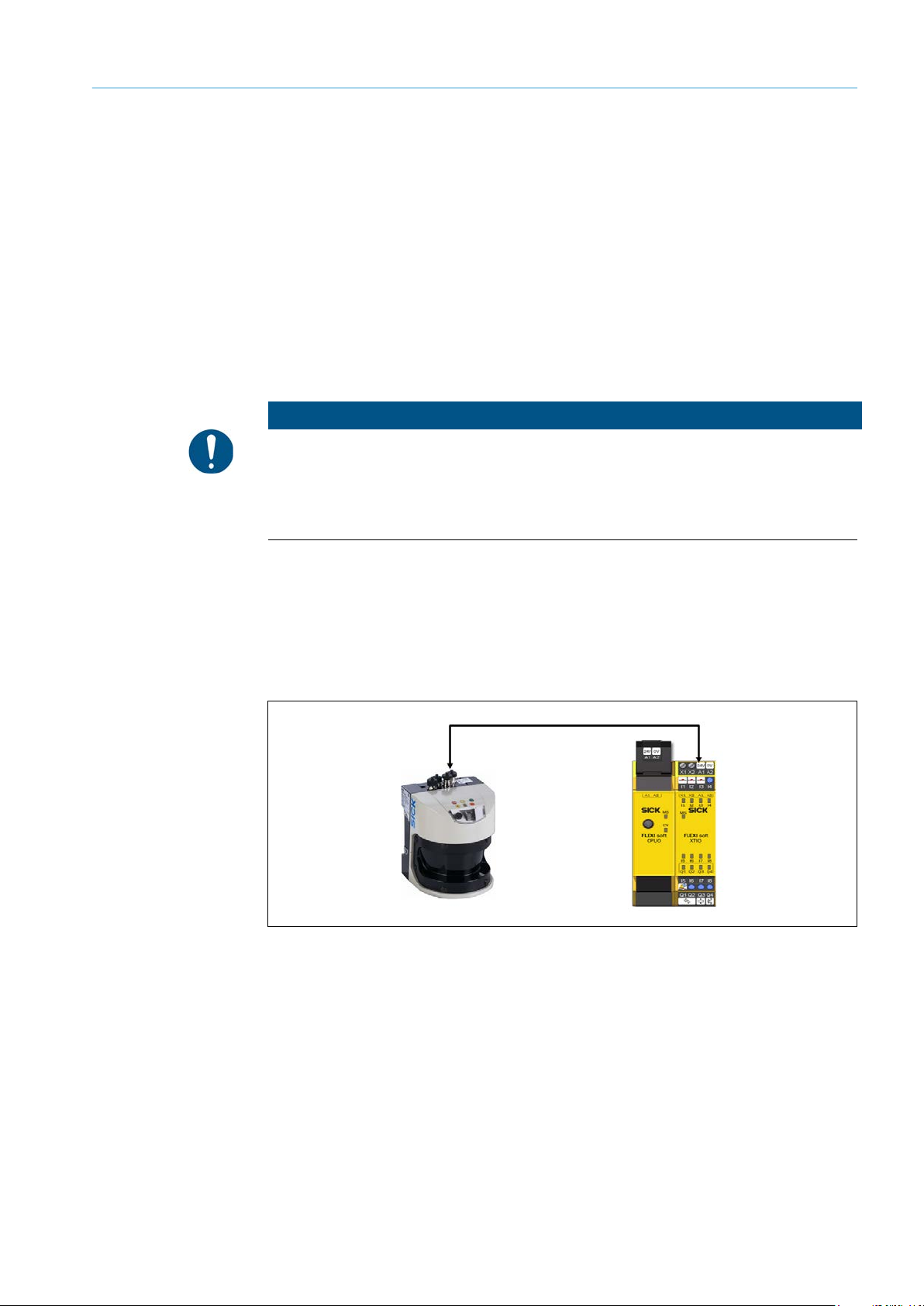
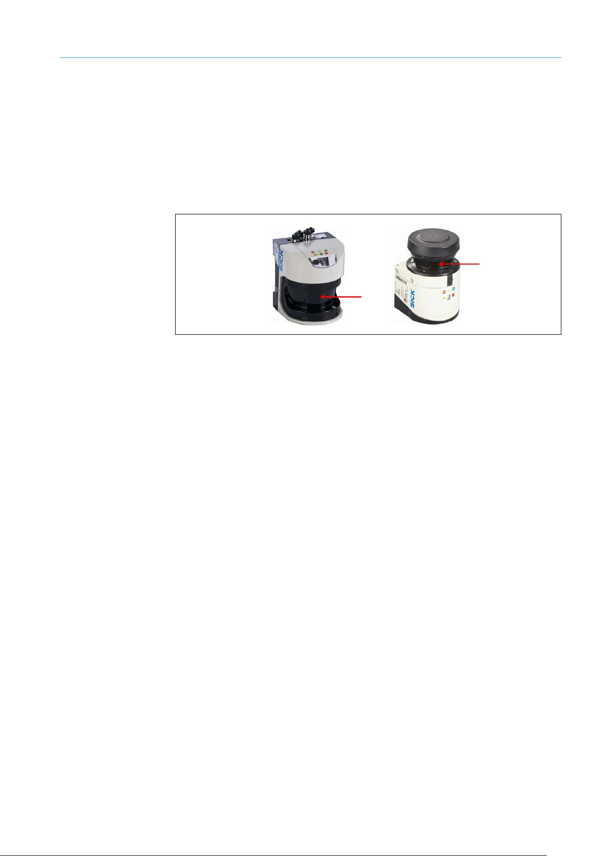
3.1.1 Scope of delivery, AOS501-AOS504
The AOS501 configuration consists of a pre-configured LMS511 laser scanner, the
Flexi Soft control (comprising the main module and an I/O expansion module) and a
connection box for bridging large distances between the laser scanner and the terminal
compartment.
Fig. 1: Main components of the AOS Prime AOS501
Page 18

3 PRODUCT DESCRIPTION
18
8016800/ZPQ5/2017-08-15|SICK
OPERATING INSTRUCTIONS | AOS Prime
Subject to change without notice
Part No.
Quantity
Description
1064409
1
AOS501
Consisting of:
1057618
1
Laser scanner LMS511-10100S02
1043783
1
Flexi Soft main module FX3-CPU000000
1043700
1
Flexi Soft system plug FX3-MPL000001
1044125
1
Flexi Soft I/O module FX3-XTIO84002
6034574
1
USB configuration connection DSL-8U04G02M025KM1
2073337
1
USB stick with configuration file (prepared configuration for control
and laser scanner) as well as device and system documentation
6030928
1
Ethernet connection cable SSL-2J04-G10ME
1059092
1
LMS511 laser scanner accessory set 1, consisting of:
connection box
Part No.
Quantity
Description
2063050
1
Weather hood 180° LMS511
Part No.
Quantity
Description
1066130
1
AOS502
Consisting of:
1057618
2
Laser scanner LMS511-10100S02
1059092
2
Laser scanner LMS511 accessory set 1
Part No.
Quantity
Description
1066131
1
AOS503
Consisting of:
1057618
3
Laser scanner LMS511-10100S02
1044125
2
Flexi Soft I/O module FX3-XTIO84002
1059092
3
Laser scanner LMS511 accessory set 1
Part No.
Quantity
Description
1066132
1
AOS504
Consisting of:
1057618
4
Laser scanner LMS511-10100S02
1044125
2
Flexi Soft I/O module FX3-XTIO84002
1059092
4
Laser scanner LMS511 accessory set 1
AOS501
The “SOPAS” and Flexi Soft Designer configuration tools can be downloaded at
www.sick.com.
Optional
AOS502
Scope of delivery includes the same items listed for the AOS501, except for the following
differences:
Connection box for power, I/O and RS-232/-422 data
Mounting kit for mounting the laser scanner and
AOS503
AOS504
Scope of delivery includes the same items listed for the AOS501, except for the following
differences:
Scope of delivery includes the same items listed for the AOS501, except for the following
differences:
Page 19

19
8016800/ZPQ5/2017-08-15|SICK
Subject to change without notice
OPERATING INSTRUCTIONS | AOS Prime
3.1.2 Scope of delivery, AOS101-AOS104
Part No.
Quantity
Description
1064408
1
AOS101
Consisting of:
1047516
1
Laser scanner LMS111-10100S01
1043783
1
Flexi Soft main module FX3-CPU000000
1043700
1
Flexi Soft system plug FX3-MPL000001
1044125
1
Flexi Soft I/O module FX3-XTIO84002
6034574
1
USB configuration connection DSL-8U04G02M025KM1
operating instructions
2062346
1
Connection box for power, I/O and RS-232/RS-422 data (not
Ethernet), with three pre-wired M12 cables, 8-pin
2046025
1
Mounting kit for laser scanner
6030928
1
Ethernet connection cable SSL-2J04-G10ME
Part No.
Quantity
Description
2046458
1
LMS111 weather hood 270°
Part No.
Quantity
Description
1066127
1
AOS102
Consisting of:
1047516
2
Laser scanner LMS111-10100S01
2062346
2
Connection box
2046025
2
Mounting kit for laser scanner
The AOS101 configuration consists of a pre-configured LMS111 laser scanner and the
Flexi Soft control, which consists of the main module and an I/O expansion module. The
laser scanner is connected to the Flexi Soft control via pre-wired configuration cables.
Fig. 2: Main components of the AOS Prime AOS101
AOS101
PRODUCT DESCRIPTION 3
Optional
AOS102
2073337 1 USB stick with configuration files and “AOS Prime”
The “SOPAS” and Flexi Soft Designer configuration tools can be downloaded at
www.sick.com.
Scope of delivery includes the same items listed for the AOS101, except for the following
differences:
Page 20

3 PRODUCT DESCRIPTION
20
8016800/ZPQ5/2017-08-15|SICK
OPERATING INSTRUCTIONS | AOS Prime
Subject to change without notice
Part No.
Quantity
Description
1066128
1
AOS103
Consisting of:
1047516
3
Laser scanner LMS111-10100S01
1044125
2
Flexi Soft I/O module FX3-XTIO84002
2062346
3
Connection box
2046025
3
Mounting kit for laser scanner
Part No.
Quantity
Description
1066129
1
AOS104
Consisting of:
1047516
4
Laser scanner LMS111-10100S01
1044125
2
Flexi Soft I/O module FX3-XTIO84002
2062346
4
Connection box
2046025
4
Mounting kit for laser scanner
AOS103
AOS104
Scope of delivery includes the same items listed for the AOS101, except for the following
differences:
Scope of delivery includes the same items listed for the AOS101, except for the following
differences:
Page 21
21
8016800/ZPQ5/2017-08-15|SICK
Subject to change without notice
OPERATING INSTRUCTIONS | AOS Prime
3.2 Components in the system
3.2.1 The LMS511/LMS111 laser scanners
The LMS511 or LMS111 laser scanners, whose use depends on the application requirements, are laser measurement sensors that scan their environment in two dimensions
using a time-of-flight method. When a sent laser beam is reflected by a target object, the
position of the object is determined as a distance and an angle and output to the data
interface and supplied to the internal field evaluation.
The laser output occurs at the front screen. It is indicated by a corresponding mark.
Fig. 3: Laser output aperture on the LMS511 / LMS111 laser scanner
Different monitoring fields are defined within the scanning range of the laser scanners
(scanning range). Each monitoring field is linked to at least one evaluation case; the
assigned switching output is triggered if the respective field is infringed (object detection
in the monitoring field).
The LMS511 laser scanner has a monitoring radius of 80 m / 38 m for black objects with
10% remission and a scanning angle of 190°. The monitoring radius of the LMS111 laser
scanner is 20 m / 18 m for black objects with 10% remission. The scanning angle is 270°.
All input and output signals from the laser scanner are directly connected to the central
Flexi Soft control, which evaluates the laser scanner information accordingly (see below).
The laser measurement sensors are designed for outdoor use in harsh ambient conditions.
In order to withstand such conditions, the devices have various filter technologies and an
internal heater. They are also equipped with weather hoods.
Both laser scanners feature automatic contamination measuring for the front screen.
The contamination signals can be merged using the central Flexi Soft control and can be
output via a shared application diagnostic output.
PRODUCT DESCRIPTION 3
Page 22

3 PRODUCT DESCRIPTION
22
8016800/ZPQ5/2017-08-15|SICK
OPERATING INSTRUCTIONS | AOS Prime
Subject to change without notice
Note
The laser scanner can evaluate multiple reflection pulses. Additional reflective pulses occur
when the laser beam hits smaller particles such as snowflakes or raindrops. In very harsh
environments, the laser scanner can also be switched to evaluate the last echo if necessary.
Fig. 4: Evaluation of reflection pulses by the laser scanner
For detailed information about the operating principle of the LMS laser scanner, please
refer to the operating instructions of the respective devices.
3.2.2 The Flexi Soft control
The Flexi Soft control consists of the CPU0 central main module (1) and at least one XTIO
I/O expansion module (2).
Note
Fig. 5: Flexi Soft safety control components
• The CPU0 main module is the central logic unit of the control. Here, all signals are
analyzed and evaluated within the configured logic. The result of this processing is
transmitted to the higher-level machine or system control via the I/O module.
The configuration can be edited and adapted to the requirements of the individual
application. For this purpose, the main module has an M8 configuration connection.
• The XTIO I/O expansion module provides the I/O input and output signals from
the AOS Prime. The communication with the connected laser scanners and with the
downstream machine control occurs via the switching signals of the AOS Prime.
One XTIO I/O expansion module is necessary for every two laser scanners. One laser
scanner uses three switching inputs in the basic version. Signals are communicated to
the upper-level system control via switching outputs.
It is possible to attach additional XTIO modules according to the expansion desired.
In total, the control can be used to operate up to 12 modules (144 I/O signals).
Different configurations are supplied for the Flexi Soft control. The appropriate control
configuration for the system can be carried out by downloading a file. This file already
contains all AOS functions necessary for checking both the object detection system and
the internal self-test of the sensors.
Page 23
23
8016800/ZPQ5/2017-08-15|SICK
Subject to change without notice
OPERATING INSTRUCTIONS | AOS Prime
3.2.3 The test target
No.
Meaning
1
Monitoring field
2
Test target
The self-diagnosis of the object detection system occurs via the continuous detection of
an external test target. During this process, the corresponding scanner monitoring field
is infringed by the test target. Only by using external test targets can the full functional
range of the AOS Prime object detection system be ensured.
At least one external test target is required for each laser scanner. It is also possible to
use a shared test target for multiple laser scanners.
A stationary body located outside the actual object detection monitoring area can be used
as a test target.
PRODUCT DESCRIPTION 3
Note
Fig. 6: Detection of a test target
Tab. 2: Status indicators on the Flexi Soft main module
The surface of the test target should be flat. For example, sheets, panels or even a
suitable part of the monitored machine are appropriate test targets. In order to avoid
reflections on the surface of the external test target, the area of the test target must not
be covered with a glossy coating. The color of the test target should be consistent with
the color of the objects that are to be detected.
The width of the test target must be at least 30 mm. The following applies to the minimum
width of the test target as a rule of thumb at distances > 1.5 m to the test target:
Width of test target [mm] = target scanning range [mm] / 50.
To determine the exact diameter of the light spot, please consult the operating
instructions for the corresponding laser scanner.
Alternatively, it is possible to use a stationary machine or system part as a test target.
Page 24

3 PRODUCT DESCRIPTION
24
8016800/ZPQ5/2017-08-15|SICK
OPERATING INSTRUCTIONS | AOS Prime
Subject to change without notice
3.2.4 The connection box of the laser scanner
Using the connection box, connecting the laser scanner and the control cabinet to the
Flexi Soft control is easy. The connection box is delivered with the AOS Prime systems by
default.
Separate installation cables are routed from the Flexi Soft to the connection box on-site
to produce the connection. The connection box is connected to the laser scanner via the
pre-configured cables (see chapter 5.1 Connecting the LMS511 laser scanner).
When using the AOS Prime in the AOS10x configuration, the LMS111 laser scanners
are also connected to the Flexi Soft using the configured connection box or using system
cables (max. 20 m) (see chapter 5.2 Connecting the LMS111 laser scanner).
Page 25
25
8016800/ZPQ5/2017-08-15|SICK
Subject to change without notice
OPERATING INSTRUCTIONS | AOS Prime
3.3 Principle of operation
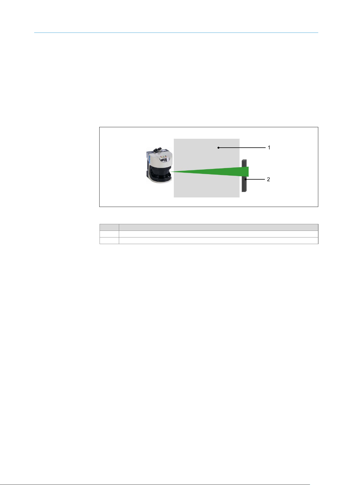
The AOS Prime is a self-testing object detection system whose functionality as a whole is
monitored by the Flexi Soft safety control.
Monitoring fields and evaluation cases
The monitored area scanned by the laser scanners is divided into different fields. The size
and geometry of the monitoring fields can vary and must be configured on-site.
Fig. 7: Predefined monitoring fields in the AOS Prime
In the AOS Prime, the following standard monitoring fields are available:
• Stopping field (1) e.g., for stopping the system or a movement direction on a mobile
system.
• Warning field (2) e.g., for advance warning or reduction of speed on a mobile system.
• Test field (3) for detecting an external test target.
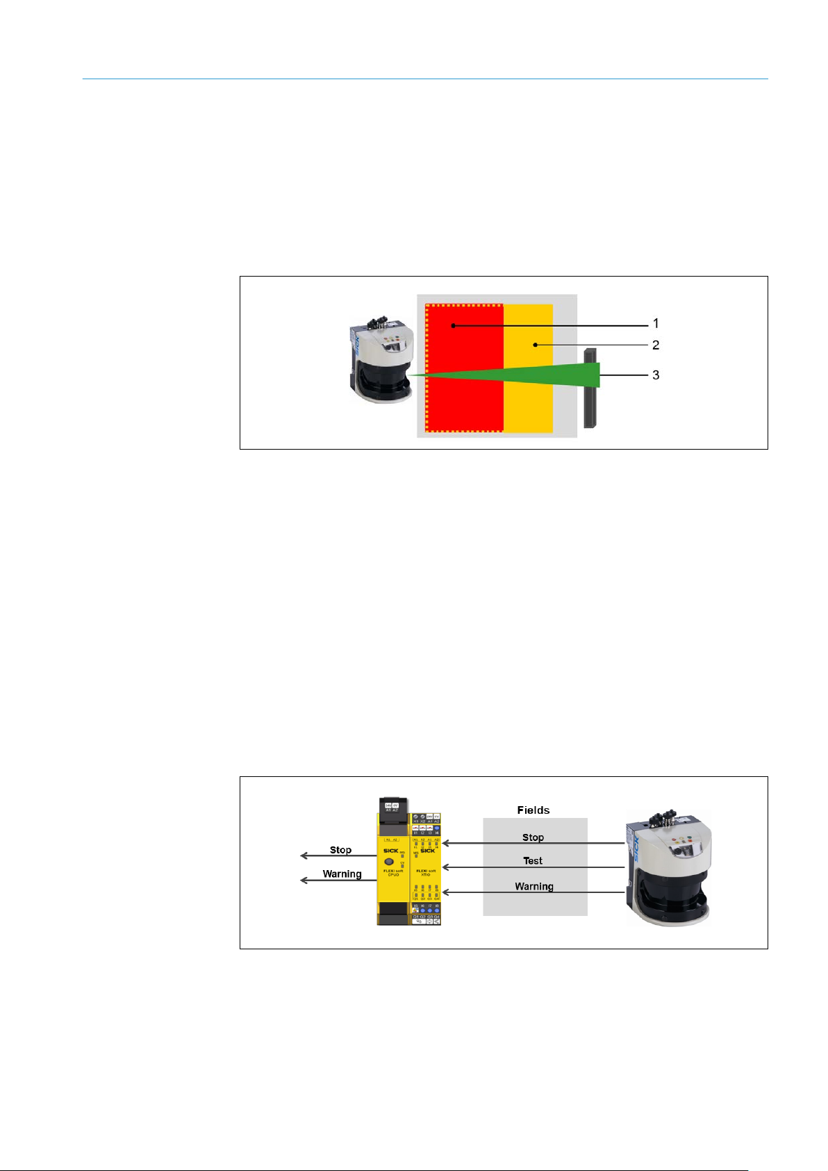
Switching signals in object detection
The laser scanners operate internally with so-called evaluation cases that are assigned
to the monitoring fields. If a monitoring field is infringed, this will be signaled by the
corresponding switching output on the laser scanner.
The Flexi Soft analyzes the information from the laser scanner and transmits the
corresponding results, such as “Warning field infringed” or “Stopping field infringed”,
to the upper-level system control.
PRODUCT DESCRIPTION 3
Note
Fig. 8: Switching signals for object detection
Additional control tasks, such as an emergency stop or the evaluation of, for example,
limit switches, are also possible with the Flexi Soft. However, they are not the primary
feature of the AOS Prime object detection system!
Page 26
3 PRODUCT DESCRIPTION
26
8016800/ZPQ5/2017-08-15|SICK
OPERATING INSTRUCTIONS | AOS Prime
Subject to change without notice
Switching signals in self-diagnostics
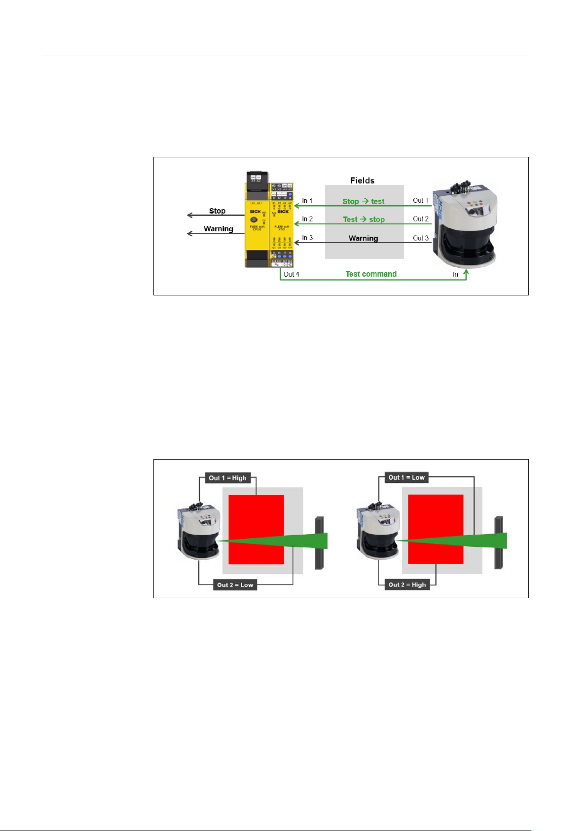
The Flexi Soft control also handles the internal self-testing of the laser scanners. For this
purpose, the control cyclically sends a changeover signal to the laser scanner to switch
the assignment of the monitoring and test fields to the switching output (= switching
evaluation fields).
Fig. 9: Switching signals for the internal self-testing of the AOS Prime
The change in the assignment of stopping and warning fields causes the switching outputs
to respond with a signal change from High to Low or, conversely, from Low to High. The
control performs the safety-related plausibility check of the individual changes expected in
the laser scanner switching signals.
In the example below, output Out 1 reports an intact stopping field prior to the changeover
signal (test command) by sending a High signal, and output Out 2 reports the detected
test target by sending a Low signal.
After the changeover signal, output Out 1 reports the detected test target (Low signal)
and output Out 2 reports the intact stopping field (High signal).
Note
Fig. 10: Switching signals of the self-test
The test response from the laser scanner (on/off switching operation at the outputs)
occurs once the response time set on the laser scanner has expired, e.g., after 180 msec.
The Flexi Soft wait time for the test response from the laser scanner must always be
longer than the actual response time of the laser scanner (e.g. wait time = 1 sec., laser
scanner response time = 500 msec.).
In exceptional cases, the predefined wait time must be adjusted via the Flexi Soft
parameters.
Page 27
27
8016800/ZPQ5/2017-08-15|SICK
Subject to change without notice
OPERATING INSTRUCTIONS | AOS Prime
What errors can be detected?
Display
Meaning
Laser scanner in operation, no evaluation cases are reporting an event
Optics cover is dirty
Switching output switched
Laser scanner is in teach-in mode
The internal self-test ensures that the test target is continuously detected by the laser
scanner. If a correct response is not given, the control is locked and sends a stop signal
to the upper-level machine control.
Incorrect responses can, for example, have the following causes:
• Defective laser scanner
• Missing test target
• Improper laser scanner adjustment (mechanical error or manipulation)
• Physically defective switching output on the laser scanner or short-circuit to VDC,
cross-talk or short to ground
• Cable break
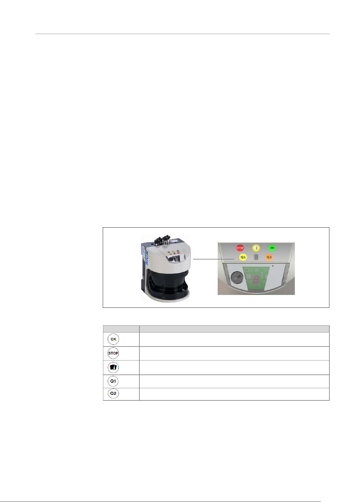
3.4 Status indicators
Status indicators are located on the laser scanners and the Flexi Soft control.
3.4.1 LEDs on the LMS111 / LMS511 laser scanner
PRODUCT DESCRIPTION 3
In normal operation, the laser scanner is fully automatic—no operator intervention is
required. The LEDs and 7-segment display signal the operational status of the LMS111
and LMS511 laser scanner.
Fig. 11: Laser scanner status indicators (pictured: the LMS511 laser scanner)
Laser scanner in operation, at least one evaluation case reports an event
Tab. 3: Status indicators on the laser scanner
The 7-segment display is used for diagnostics when errors or faults occur (see chapter 8.3
Fault indicator on the LMS511 / LMS111 laser scanners).
Page 28

3 PRODUCT DESCRIPTION
28
8016800/ZPQ5/2017-08-15|SICK
OPERATING INSTRUCTIONS | AOS Prime
Subject to change without notice
LED
Display
Meaning
MS Green
Module status, illuminated green during proper control operation.
MS Green
(1 Hz)
System in stopped status. Start application in Flexi Soft Designer.
CV
Configuration in process.
CV Yellow
(2 Hz)
The configuration is being permanently saved. Do not disconnect
from power supply until save process has been completed.
CV Yellow
(1 Hz)
Unverified configuration. The configuration must be verified by
the Flexi Soft Designer.
CV Yellow
Verified configuration, illuminated yellow once configuration has
been verified.
LED
Display
Meaning
MS
Module status, illuminated green during proper operation of
expansion module.
MS
System in stopped status. Start application in Flexi Soft Designer.
I/O Input/output is deactivated.
CV
Input/output is deactivated.
3.4.2 LEDs on the Flexi Soft
Main module
CPU0
Fig. 12: Status indicators on the Flexi Soft main module
I/O module
Tab. 4: Status indicators on the Flexi Soft main module
Fig. 13: Status indicators on the Flexi Soft expansion module
Green
Green
Green
Tab. 5: Status indicators on the Flexi Soft expansion module
Page 29

29
8016800/ZPQ5/2017-08-15|SICK
Subject to change without notice
OPERATING INSTRUCTIONS | AOS Prime
3.5 Parameter memory
3.5.1 Parameter set on connector plug of the Flexi Soft control unit
The system configuration parameters are saved on the connector plug of the Flexi Soft
CPU0 main module. This allows the main or expansion modules to be replaced without
having to reconfigure the Flexi Soft control (see chapter 7.3.2 Replacing Flexi Soft
safety control modules).
3.5.2 Parameter set in the laser scanner
All monitoring field with the basic field geometries as well as the necessary evaluation
cases are already pre-configured and permanently saved (factory settings) in this laser
scanner. Changes to the configuration (e.g. field geometries) are done using SOPAS
configuration software. The configuration can be saved in a file and transferred to the
replacement device when a laser scanner is replaced (see chapter 7.3.1 Replacing a
laser scanner).
PRODUCT DESCRIPTION 3
Page 30

4 MOUNTING
30
8016800/ZPQ5/2017-08-15|SICK
OPERATING INSTRUCTIONS | AOS Prime
Subject to change without notice
WARNING
4 Mounting
4.1 Planning mounting locations
The reliable and problem-free operation of the AOS Prime depends primarily on the proper
planning and mounting of the laser scanners.
Laser scanner
• The laser scanners must have sufficient mechanical protection. Only with optimal
positioning is it possible to adequately protect the system against collisions.
• Always be sure that the laser scanner has an unobstructed view of the areas that are
to be monitored.
• The laser scanners must be mounted in such a manner that they can detect objects
that penetrate the monitored area.
Test target
The test target must be mounted in such a way that the laser beam impinges on the
surface of the test target as vertically as possible.
Notes on the scanning field
When planning to mount the laser scanners, be sure to consider the fact that the laser
beam widens as the distance from the laser to mount the laser scanner increases.
As a result, the ground or a wall panel within the scanned area could end up being
permanently detected under unfavorable conditions because it is being hit by the laser
beam.
Recommendation
Detailed information on the operating principle of the laser measurement sensors can
be found in the operating instructions for the LMS511 and LMS111 laser scanners.
4.2 Mounting the laser scanners
4.2.1 General notes
Mount the laser scanners at the designated locations. Be sure to observe the detailed
drawings and information in the operating instructions for the LMS511 or LMS111 laser
scanner.
Be sure to closely observe the following notes during mounting:
Mount the laser scanner so that it is protected from dirt and damage.
▸
Ensure that the field of view of the entire front screen is not restricted.
▸
Always mount the laser scanner such that you are able to insert and remove the
▸
connector plug.
Avoid excessive shock and vibration exposure of the laser scanner.
▸
For systems that vibrate heavily, use shock absorbers to prevent the possibility of
▸
fixing screws coming loose unintentionally.
Page 31

MOUNTING 4
31
8016800/ZPQ5/2017-08-15|SICK
Subject to change without notice
OPERATING INSTRUCTIONS | AOS Prime
Weather hood
Because of the ambient conditions, a weather hood is always recommended.
The weather hood also protects the laser scanner from direct sunlight on the scanner
housing (overheating) and, to a great extent, from dazzling resulting from sunlight or other
light sources.
4.2.2 Mounting the LMS511 laser scanner
The LMS511 laser scanner is ideally mounted so that the connector plug faces down
so that the contamination diagnostics are not affected – regardless of whether or not a
weather hood is being used.
Fig. 14: Mounting the 511 laser scanner
Mounting the LMS511 laser scanner
Fig. 15 Mounting kit for the LMS511 laser scanner
1. Mount the wall-mounting kit on the desired mounting surface.
2. Mount the mounting bracket with the adapter plate on the wall-mounting kit.
3. Mount the connector box on the adapter plate of the mounting bracket.
4. Mount the LMS511 laser scanner on the mounting bracket.
5. Adjust the LMS511 laser scanner longitudinally and crosswise.
Mounting the connection box
Mount the local connection box next to or above the LMS111
▸
Page 32

4 MOUNTING
32
8016800/ZPQ5/2017-08-15|SICK
OPERATING INSTRUCTIONS | AOS Prime
Subject to change without notice
4.2.3 Mounting the LMS 111 laser scanner
The preferred mounting position of the LMS111 laser scanner is with the connector
plugs facing up. The weather hood should be mounted on the device accordingly (see the
operating instructions for the LMS511 laser scanner).
Fig. 16: Mounting the 111 laser scanner
Mounting the LMS111 laser scanner
Fig. 17 Mounting kit for the LMS111 laser scanner
1. Mount the lower part of the mounting bracket on the mounting surface.
2. Mount the LMS111 laser scanner on the upper part of the mounting bracket.
3. Mount the LMS111 laser scanner on the lower part of the bracket with the upper part.
Fig. 18: LMS111 laser scanner with mounting kit and weather hood
Mounting the connection box
Mount the local connection box next to or above the LMS111
▸
Page 33

33
8016800/ZPQ5/2017-08-15|SICK
Subject to change without notice
OPERATING INSTRUCTIONS | AOS Prime
4.3 Mounting the Flexi Soft control
WARNING
Consider the protection class
The Flexi Soft control has an IP 20 protection class and must always be mounted in an
electric or control cabinet.
The Flexi Soft control should be mounted in a suitable location in the control cabinet.
Ideally, it should be mounted near the higher-level control but never in the vicinity of
transformers, contactors or other power units.
In order to accommodate the leads and wiring, there must be enough terminals available.
Mounting
Mount the Flexi Soft control modules in a suitable location on the mounting rail in the
control cabinet.
1. Hang the module on the mounting rail.
MOUNTING 4
Note
Fig. 19: Mounting the Flexi Soft modules
2. Ensure the correct fit of the grounding spring. The grounding spring of the module must
be flush against the mounting rail such that it is secure and can suitably conduct
electricity.
3. Snap the module into place on the mounting rail by applying slight pressure in the
direction of the arrow.
If multiple modules are present, slide each of the modules together in the direction of the
arrow until the side-mounted plug connector engages.
Install end pieces on the left and right sides.
Page 34

4 MOUNTING
34
8016800/ZPQ5/2017-08-15|SICK
OPERATING INSTRUCTIONS | AOS Prime
Subject to change without notice
4.4 Mounting and positioning the test targets
Because the LMS511 and LMS111 laser scanners have different detection sensitivities,
the related test targets must be positioned differently. The test target must always be
located within the scanning range of the respective laser scanner, but it must be located
outside of the monitoring field.
Check whether there is a system part that would be suitable for use as a test target. If
none can be found, mount a suitable test target. The distances indicated below serve as
standard values.
Laser scanner LMS511
If using an LMS511 laser scanner (1), do not mount the test target (2) too close to the
LMS511. The standard value for the minimum distance from the laser scanner is 0.5 m.
Fig. 20: Mounting the test target for the LMS511 laser scanner
Page 35

35
8016800/ZPQ5/2017-08-15|SICK
Subject to change without notice
OPERATING INSTRUCTIONS | AOS Prime
Note
MOUNTING 4
Laser scanner LMS111
If using an LMS111 laser scanner (1), mount the test target (2) at close range. The
standard value is a distance of 500 mm from the device.
Fig. 21: Mounting the test target for the LMS111 laser scanner
Because the LMS111 laser scanner has a scanning angle of 270°, test targets can also
be positioned to the rear or the side.
The laser beam should hit the test target perpendicularly.
Page 36

5 ELECTRICAL INSTALLATION
36
8016800/ZPQ5/2017-08-15|SICK
OPERATING INSTRUCTIONS | AOS Prime
Subject to change without notice
HAZARD
HAZARD
Wire cross-section
mm2
AWG
Solid wire
0.2 to 2.5 mm2
AWG 24 to 12
Stranded wire (flexible)
0.34 to 1.5 mm2
AWG 22 to 16
Main module / Expansion module
Power supply
A1
+24 V
A2
0 V
5 Electrical installation
Disconnect the power to the system
Make sure that all AOS Prime components are disconnected from the power supply
▸
during electrical installation.
Risk of injury due to electrical current
Standard safety requirements must be met when working on electrical systems.
▸
The power supply must be disconnected when attaching and detaching electrical
▸
connections.
5.1 Connecting Flexi Soft to the power supply
The connections on the Flexi Soft control can be used with cables of solid wire or stranded
wire. The following table shows the proper wire cross-sections for connection to the
terminals.
Note
Tab. 6: Wire cross-sections for the Flexi Soft control connections
The Flexi Soft and the laser scanners must be connected to the same power supply.
If using multiple power supplies, a 0 V equalization between the individual power supplies
must be established.
Attach the Flexi Soft main module and the I/O expansion modules to the power supply.
▸
Fig. 22: Connecting the Flexi Soft main module and I/O module to the power supply
Wire the modules to the power supply as follows:
▸
Tab. 7: Connecting the Flexi Soft main module and I/O module to the power supply
Page 37

37
8016800/ZPQ5/2017-08-15|SICK
Subject to change without notice
OPERATING INSTRUCTIONS | AOS Prime
5.2 Connecting the LMS511 laser scanner
Cable no. (in picture)
Laser scanner connection
1
I/O cable
2
Data/Input cable
3
Power supply
The connection of the LMS511 laser scanner to the Flexi Soft control takes place via the
connection box.
Prerequisites
It is assumed that a separate installation cable has been routed from the control cabinet
to the connection box or to the LMS511 laser scanner.
• It is necessary to use a shielded cable.
• The cable must have at least 6 wires (recommendation: 9 wires).
• You should also include spare wires (e.g., if you wish to energize the heater on the laser
scanner separately or lead optional signals).
Note
Recommendation
Take into account the voltage drop with long cables, especially when operating the heater.
Cabling principle
The cabling concept is always the same, regardless of whether you are connecting one
laser scanner or multiple laser scanners to the control. The number of connected laser
scanners is signaled to the Flexi Soft control by the control file provided. The respective
file is transferred to the control using Flexi Soft Designer (download).
Be sure to also observe the electrical diagrams contained in the annex to these
operating instructions!
ELECTRICAL INSTALLATION 5
5.2.1 Connecting the connection box to the LMS511 laser scanner
The connection box and the LMS511 laser scanner are connected via the pre-mounted
cables on the connection box.
Fig. 23: Connection of the LMS511 laser scanner and the connection box
Using the M12 round connectors, screw the pre-mounted cables onto the connections
▸
on the LMS511 laser scanner as indicated below.
Tab. 8: Connection of LMS511 laser scanner and connection box
Page 38

5 ELECTRICAL INSTALLATION
38
8016800/ZPQ5/2017-08-15|SICK
OPERATING INSTRUCTIONS | AOS Prime
Subject to change without notice
Pin
Wire no.
Connection
19 1 Voltage 24 V
20 2 Ground
06 3 Input 1 (test signal from Flexi Soft)
4 Not assigned (spare)
11 5 Output 1 (stop/test field status)
12 6 Output 2 (test/stop field status)
13 7 Output 3 (warning)
5.2.2 Connecting the installation cable in the connection box
The wires of the routed installation cable must be connected in the terminal block of the
connection box on the LMS511 laser scanner.
Note
To provide a clearer overview, the wires in the figures below are numbered.
Connect the wires in the terminal block of the connection box as follows:
▸
Notes
Fig. 24: Connecting wires in the connection box (min. wiring)
Tab. 9: Connecting wires in the connection box (min. wiring)
• The wire jumpers indicated for voltage and ground are not contained in the connection
box at delivery. You must lay the bridges on the connection side.
• When using a common power supply unit for the sensor and heater, the power supply
unit must fulfill the requirements of the sensor part.
• If two separate power supply units are used for the sensor and the heater, terminals
19-21 and 20-22 are not jumpered. The 0-V outputs of both power supply units must
be connected for potential equalization.
Page 39

39
8016800/ZPQ5/2017-08-15|SICK
Subject to change without notice
OPERATING INSTRUCTIONS | AOS Prime
5.2.3 Wiring the installation cable wires to the Flexi Soft control
No.
Connection
Voltage supply
1
Voltage
+24 V
2
Ground
0 V
The individual wires of the installation cable are connected in the control cabinet and
wired to the Flexi Soft control module.
Wiring the power supply in the control cabinet
Connect the wires for the power supply to the terminals in the control cabinet.
▸
ELECTRICAL INSTALLATION 5
Fig. 25: Connecting the power supply to terminals in the control cabinet (LMS511 laser scanner)
Connect the wires to the power supply in the control cabinet as follows:
▸
Tab. 10: Connecting the power supply to terminals in the control cabinet (LMS511 laser scanner)
Page 40

5 ELECTRICAL INSTALLATION
40
8016800/ZPQ5/2017-08-15|SICK
OPERATING INSTRUCTIONS | AOS Prime
Subject to change without notice
No.
Connection
I/O expansion module
3
Switching output (test signal to LMS)
Q4
5
Switching input (stop/test field status)
I1 6 Switching input (test/stop field status)
I2
7
Switching input (warning field status)
I3
Connection
Voltage
supply
I/O expansion module
Voltage
+24 V
Ground
0 V
Switching output (test signal to LMS)
Q4
Switching input (stop/test field status)
I5
Switching input (test/stop field status)
I6
Switching input (warning field status)
I7
Wiring inputs and outputs in the control cabinet
Connect the wires for the input and output switching signals in the control cabinet as
▸
follows:
Fig. 26: Wiring the switching inputs and outputs in the control cabinet (LMS511 laser scanner)
Connect the wires to the I/O expansion module as follows:
▸
Tab. 11: Wiring the switching inputs and outputs in the control cabinet (LMS511 laser scanner)
5.2.4 Connecting additional LMS511 laser scanners to Flexi Soft
Connecting a second LMS511 laser scanner to the Flexi Soft takes place as indicated in
the following table:
Tab. 12: Connecting a second LMS511 laser scanner to the Flexi Soft
A second I/O expansion module is required to connect a third and fourth LMS511 laser
scanner. Connection follows the same principle as for the first I/O expansion module.
Note
The appropriate configuration file for configuring the Flexi Soft control must be loaded
according to the number of laser scanner connected. This file is included in the AOS Prime
scope of delivery.
Page 41

41
8016800/ZPQ5/2017-08-15|SICK
Subject to change without notice
OPERATING INSTRUCTIONS | AOS Prime
5.3 Connecting the LMS111 laser scanner
The LMS111 laser scanner can be connected using one of two methods:
• Using the local connection box (= scope of delivery).
• Using system cables (= existing systems).
5.3.1 Using the local connection box
The connection of the LMS111 laser scanner to the Flexi Soft control takes place via the
connection box.
Prerequisites
It is assumed that a separate installation cable has been routed from the control cabinet
to the connection box or to the LMS511 laser scanner.
• It is necessary to use a shielded cable.
• The cable must have at least 7 wires.
• You should also include spare wires (e.g., if you wish to energize the heater on the laser
scanner separately or lead optional signals).
Note
Recommendation
Take into account the voltage drop with long cables, especially when operating the heater.
Cabling principle
The cabling concept is always the same, regardless of whether you are connecting one
laser scanner or multiple laser scanners to the control. The number of connected laser
scanners is signaled to the Flexi Soft control by the control file provided.
Be sure to also observe the electrical diagrams contained in the annex to these operating
instructions!
ELECTRICAL INSTALLATION 5
Page 42

5 ELECTRICAL INSTALLATION
42
8016800/ZPQ5/2017-08-15|SICK
OPERATING INSTRUCTIONS | AOS Prime
Subject to change without notice
Cable no. (in picture)
Laser scanner connection
1
I/O cable
2
Data/Input cable
3
Voltage supply
5.3.1.1 Connecting the connection box to the LMS111 laser scanner
The connection box and the LMS111 laser scanner are connected via the pre-mounted
cables on the connection box.
Fig. 27: Connection of the LMS511 laser scanner and the connection box
Using the M12 round connectors, screw the pre-mounted cables onto the connections
▸
on the LMS111 laser scanner as indicated below.
Tab. 13: Connection of LMS111 laser scanner and connection box
Page 43

43
8016800/ZPQ5/2017-08-15|SICK
Subject to change without notice
OPERATING INSTRUCTIONS | AOS Prime
5.3.1.2 Connecting the installation cable in the connection box
Pin
Wire no.
Connection
17 1 Voltage 24 V
18 2 Ground
06 3 Input 1 (test signal from Flexi Soft)
4 Not assigned (spare)
12 5 Output 1 (stop/test field status)
13 6 Output 2 (test/stop field status)
14 7 Output 3 (warning)
The wires of the routed installation cable must be connected in the terminal block of the
connection box on the LMS111 laser scanner.
Note
To provide a clearer overview, the wires in the figures below are numbered.
Connect the wires in the terminal block of the connection box as follows:
▸
ELECTRICAL INSTALLATION 5
Notes
Fig. 28: Connecting wires in the connection box (min. wiring)
Tab. 14: Connecting wires in the connection box (min. wiring)
• The wire jumpers indicated for voltage and ground are not contained in the connection
box at delivery. You must lay the bridges on the connection side.
• When using a common power supply unit for the sensor and heater, the power supply
unit must fulfill the requirements of the sensor part.
• If two separate power supply units are used for the sensor and the heater, terminals
17-19 and 18-20 are not jumpered. The 0-V outputs of both power supply units must
be connected for potential equalization.
Page 44

5 ELECTRICAL INSTALLATION
44
8016800/ZPQ5/2017-08-15|SICK
OPERATING INSTRUCTIONS | AOS Prime
Subject to change without notice
No.
Connection
Voltage supply
1
Voltage
+24 V
2
Ground
0 V
5.3.1.3 Wiring the installation cable wires to the Flexi Soft control
The individual wires of the installation cable are connected in the control cabinet and
wired to the Flexi Soft control module.
Wiring the power supply in the control cabinet
Connect the wires for the power supply to the terminals in the control cabinet.
▸
Fig. 29: Connecting the power supply to terminals in the control cabinet (LMS111 laser scanner)
Connect the wires to the power supply in the control cabinet as follows:
▸
Tab. 15: Connecting the power supply to terminals in the control cabinet (LMS111 laser scanner)
Page 45

ELECTRICAL INSTALLATION 5
45
8016800/ZPQ5/2017-08-15|SICK
Subject to change without notice
OPERATING INSTRUCTIONS | AOS Prime
No.
Connection
I/O expansion module
3
Switching output (test signal to LMS)
Q4 5 Switching input (stop/test field status)
I1
6
Switching input (test/stop field status)
I2
7
Switching input (warning field status)
I3
Wiring inputs and outputs in the control cabinet
Connect the wires for the input and output switching signals in the control cabinet as
▸
follows:
Fig. 30: Wiring the switching inputs and outputs in the control cabinet (LMS111 laser scanner)
Connect the wires to the I/O expansion module as follows:
▸
Tab. 16: Wiring the switching inputs and outputs in the control cabinet (LMS111 laser scanner)
Page 46

5 ELECTRICAL INSTALLATION
46
8016800/ZPQ5/2017-08-15|SICK
OPERATING INSTRUCTIONS | AOS Prime
Subject to change without notice
NOTE
No.
Cable
Plug connector
1
Voltage supply (female connector – open)
M12 female connector, 5-pin,
straight, A-coded, cable, 20 m, 4-wire
2
Data/Input configuration cable, shielded
(female connector – open)
M12 female connector, 8-pin,
straight, A-coded, cable, 20 m, 8-wire
3
I/O configuration cable, shielded
(male connector – open)
M12 male connector, 8-pin, straight,
A-coded, cable, 20 m, 8-wire
5.3.2 Using the pre-configured system cables
5.3.2.1 Overview of pre-configured system cables
The following description is only valid for already-existing systems.
Cabling the LMS111 laser scanner to the Flexi Soft control is done via pre-configured
cables that are included in the AOS Prime 10x scope of delivery. The cables have an M12
plug connector on one side. The other end is open with a shield.
Fig. 31: Pre-configured cables for connecting the LMS111 laser scanner
Tab. 17: Pre-configured cables for connecting the LMS111 laser scanner
5.3.2.2 Wiring the system cables in the control cabinet
The cabling concept is always the same, regardless of whether you are connecting one
laser scanner or multiple laser scanners to the control.
The number of connected laser scanners is signaled to the Flexi Soft control by the control
file provided. The file is transferred to the control using Flexi Soft Designer.
1. Screw the M12 round connector on the LMS111 laser scanner onto the corresponding
connector.
2. Run the cable to the control cabinet.
3. Connect the wires to the terminals of the control cabinet and wire the terminals
accordingly.
Recommendation
Be sure to also observe the electrical diagrams contained in the annex to these
operating instructions!
Page 47

ELECTRICAL INSTALLATION 5
47
8016800/ZPQ5/2017-08-15|SICK
Subject to change without notice
OPERATING INSTRUCTIONS | AOS Prime
No.
Wire color
Connection
Potential
1
Brown
Sensor
+24 V
2
White
Heating
+24 V
3
Blue (yellow)
Ground sensor
0 V 4 Black (green)
Heating ground
0 V
Voltage supply cable
Fig. 32: Wiring the power supply cable (LMS111 laser scanner)
Notes
Tab. 18: Wiring the power supply cable in the control cabinet (LMS111 laser scanner)
• In the configuration cables, the ground and heater ground wires are either blue and
black or yellow and green.
• If using a shared power supply unit for the sensor and heater, then the corresponding
terminals must also be jumpered. The power supply unit must fulfill the requirements
of the laser measurement sensor.
Page 48

5 ELECTRICAL INSTALLATION
48
8016800/ZPQ5/2017-08-15|SICK
OPERATING INSTRUCTIONS | AOS Prime
Subject to change without notice
No.
Wire color
Connection
Control
Data/Input cable
1
Pink
LMS input
Q4 2 Red
GND I/O cable
1
Yellow
Output on LMS
I1 2 Gray
Output on LMS
I2 3 Pink
Output on LMS
I3 4 Blue
+24 V
Data/Input cable and I/O cable
Fig. 33: Wiring the data/input cable and I/O cable in the control cabinet (LMS111 laser scanner)
Note
Tab. 19: Wiring the data/input cable and I/O cable in the control cabinet (LMS111 laser scanner)
The other wires are not used by the AOS Prime.
Insulate the open ends.
▸
Page 49

ELECTRICAL INSTALLATION 5
49
8016800/ZPQ5/2017-08-15|SICK
Subject to change without notice
OPERATING INSTRUCTIONS | AOS Prime
Wire color
Connection
Control
Power supply cable
Brown
Sensor +24 V
White
Heater +24 V
Blue (yellow)
GND sensor
Black (green)
GND heater
Data/Input cable
Pink
Input on LMS
Q4
Red
GND I/O cable
Yellow
Output on LMS
I5
Gray
Output on LMS
I6
Pink
Output on LMS
I7
Blue
+24 V
5.3.3 Connecting additional LMS111 laser scanners to the Flexi Soft
Connecting a second LMS111 laser scanner to the Flexi Soft takes place as indicated in
the following table:
Tab. 20: Connecting a second LMS111 laser scanner to the Flexi Soft
A second I/O expansion module is required to connect a third and fourth LMS111 laser
scanner. Connection follows the same procedure as for the first I/O expansion module.
Note
The appropriate configuration file for configuring the Flexi Soft control must be loaded
according to the number of laser scanner connected. This file is included in the AOS Prime
scope of delivery.
5.4 Connecting additional I/O modules
It is possible to attach additional XTIO modules, depending on the configurations and
options. In total, the control can be used to operate up to 12 modules (144 I/O signals).
Page 50

6 COMMISSIONING
50
8016800/ZPQ5/2017-08-15|SICK
OPERATING INSTRUCTIONS | AOS Prime
Subject to change without notice
No.
LED
Display
Meaning
1
MS (main module)
Flashing red
The LED flashes red. No configuration has
been loaded yet.
2
CV (main module)
Yellow
The LED flashes yellow. The configuration
has not yet been verified in the control.
3
MS (expansion module)
Flashing red
The LED flashes red.
6 Commissioning
6.1 Switching on the supply voltage
Switch on the power supply of the object detection system.
The system starts up automatically when the power supply is connected.
Checking operating state
All AOS Prime components are thoroughly checked for operating state
The LED display for the connected laser scanner indicates the device status during the
power-up cycle.
Operating state after 60 s
The system is ready for operation after approximately 60 seconds.
6.2 Checking the operating state of the components
Once all components have been connected properly, it is possible to check whether all
devices are ready for operation after the system starts up.
6.2.1 Checking the operating state of the modular control
After system startup, the following LEDs should be illuminated on the Flexi Soft control:
Fig. 34: Checking the operating state of the Flexi Soft control
Tab. 21: First functional test of the system
Note
The switching input and output LEDs are illuminated according to the field status of the
connected laser scanners.
Page 51

51
8016800/ZPQ5/2017-08-15|SICK
Subject to change without notice
OPERATING INSTRUCTIONS | AOS Prime
6.2.2 Checking the operating state of the laser scanners
With a green LED (1), the laser measurement sensor indicates that it is ready for
operation. The OK LED must also be illuminated. The 7-segment display is blank.
Fig. 35: Checking the operating state of the laser scanners
COMMISSIONING 6
Page 52

6 COMMISSIONING
52
8016800/ZPQ5/2017-08-15|SICK
OPERATING INSTRUCTIONS | AOS Prime
Subject to change without notice
6.3 Configuring laser scanners using SOPAS
6.3.1 Overview
The AOS Prime comes with pre-configured parameters for the laser scanners. The
parameters are already located on the corresponding laser scanners.
Each parameter set, in addition to additional optional fields, contains the three basic
monitoring fields stop, test and warning, along with a predefined field geometry.
The geometries and positions of these fields must be adapted to the existing conditions
on-site.
Each monitoring field is already linked with an evaluation case with an accompanying
application condition and the assignment to the particular switching output.
The evaluation cases are standardized and do not normally need to be changed.
Pre-configured LMS511 evaluation cases
Fig. 36: Pre-configured LMS511 evaluation cases (red = AOS basic function)
Pre-configured LMS111 evaluation cases
Fig. 37: Pre-configured LMS111 evaluation cases (red = AOS basic function)
Page 53

53
8016800/ZPQ5/2017-08-15|SICK
Subject to change without notice
OPERATING INSTRUCTIONS | AOS Prime
Evaluation
case
Laser scanner input
(changeover signal)
Active field
Laser scanner output
1 0 Stop 1 2 0 Test 2 3 1 Stop 2 4 1 Test 1 5
Not relevant
Warning
3
Notes
COMMISSIONING 6
The interactive configuration of the monitoring fields takes place on-site using the SOPAS
configuration software provided. You can use the software to adjust the properties,
evaluation responses and output properties of the system as needed.
• For standard operation of the AOS Prime, the field geometries in the laser scanner only
need to be adapted to the local conditions. All other parameters are already set.
• Evaluation cases and necessary filter settings and settings for the contamination
message are already configured in the laser scanners. These do not need to be adjusted
in the standard operating mode.
Tab. 22: AOS basic function evaluation cases
Page 54

6 COMMISSIONING
54
8016800/ZPQ5/2017-08-15|SICK
OPERATING INSTRUCTIONS | AOS Prime
Subject to change without notice
6.3.2 Preparation work
6.3.2.1 Installing SOPAS
Install the latest version of the configuration software from the SICK homepage on the
configuration PC.
1. Open the www.sick.de website in the browser.
2. Enter SOPAS in the search field and start the search.
3. Download the latest version of the SOPAS Engineering Tool software and save this in
a temporary directory on the configuration PC.
4. Start the installation by double-clicking the setup.exe file.
5. Select the Installation installation type. The installation is prepared.
6. Select the user language of the wizard.
7. Click OK to confirm. The Setup Wizard opens.
8. Follow the Setup Wizard and perform the installation. Depending on the configuration,
a program group is created and an icon is placed on the desktop.
Page 55

55
8016800/ZPQ5/2017-08-15|SICK
Subject to change without notice
OPERATING INSTRUCTIONS | AOS Prime
6.3.2.2 Establishing a connection with the configuration PC
The system is configured using a configuration PC that is temporarily connected to the
respective laser scanner by an Ethernet cable.
Fig. 38: Connecting the laser scanner and the configuration PC
Note
The laser scanners are supplied with the default IP address (192.168.0.1).
Make sure that the configuration PC is in the number range of the laser scanner.
▸
If not, change the IP address of the configuration PC accordingly.
6.3.2.3 Launching SOPAS
COMMISSIONING 6
You have already connected the configuration PC to the Ethernet switch.
Launch SOPAS. The corresponding icon is located in the Windows start menu and
▸
on the desktop by default.
The initial screen is displayed. A new project is automatically created in SOPAS.
One or more devices are combined and edited in a single project.
Page 56

6 COMMISSIONING
56
8016800/ZPQ5/2017-08-15|SICK
OPERATING INSTRUCTIONS | AOS Prime
Subject to change without notice
6.3.3 Loading laser scanners into the SOPAS project
6.3.3.1 Starting the device search
Use the device search to add the connected laser scanner to a project.
Configuring the device search
1. Click the Search settings button. The Connection Wizard starts. This helps you to
establish a link with a connected device.
2. Select the Device family oriented search option and click Next to confirm.
3. Depending on the device type, select devices families LMS1xx or LMS5xx/25x in the
list to limit the device search to this device type. Click Next to confirm your selection.
Page 57

COMMISSIONING 6
57
8016800/ZPQ5/2017-08-15|SICK
Subject to change without notice
OPERATING INSTRUCTIONS | AOS Prime
4. Specify which interface is to be used for the configuration work. Since configuration is
done via an Ethernet cable, the check mark in activated in Ethernet communication
(TCP/IP).
5. Confirm the following pages of the wizard by pressing Next each time and click
Complete to finish configuring the search settings.
Starting the device search
Click on the Search devices button.
▸
If the number ranges for the configuration PC and the laser scanner correspond, then
the connected laser scanner is detected and displayed in the right side of the list of
connected devices with its device name.
Note
The laser scanner (like all SICK devices) uses two ports. Ports are part of the network
address and can be used to establish various connections between the devices. Port
2112 is freely configurable but port 2111 is a fixed port for outputting data. It is used
for device configuration.
Page 58

6 COMMISSIONING
58
8016800/ZPQ5/2017-08-15|SICK
OPERATING INSTRUCTIONS | AOS Prime
Subject to change without notice
6.3.3.2 Adding the detected laser scanner to a SOPAS project
1. Mark the detected laser scanner with port 2111 in the list.
2. Click the Add icon to transfer the laser scanner into the project. Alternatively, you can
transfer by double-clicking on the list entry or dragging and dropping.
The transferred laser scanner is displayed in the left-hand window as a tile.
Note
A (one-time) note will appear if the device drivers for the laser scanner are not yet known
in the SOPAS project. If the device has already been used, this note does not appear.
6.3.3.3 Loading device drivers into the SOPAS project
Install the device driver for the laser scanner. The device drivers can be transferred
directly from the device to SOPAS.
Getting started
1. Press OK to confirm you have seen the notification.
2. Click Install device driver in the tile.
Page 59

COMMISSIONING 6
59
8016800/ZPQ5/2017-08-15|SICK
Subject to change without notice
OPERATING INSTRUCTIONS | AOS Prime
3. You will be asked where you want to get the device drivers from. Load the device
drivers from the device and select the Device upload option.
4. Click OK to confirm. The device drivers are loaded in the SOPAS project.
It can be inferred from the tile of the laser scanner that the device is now recognized by
the configuration PC but is possibly not yet connected, meaning that it is still offline.
6.3.3.4 Opening laser scanners in SOPAS
During the initial commissioning, the standard parameters saved on the laser scanner at
the factory are transferred to the SOPAS project and then adapted to the requirements of
the relevant application there.
Fig. 39: Loading standard parameters into the SOPAS project
Page 60

6 COMMISSIONING
60
8016800/ZPQ5/2017-08-15|SICK
OPERATING INSTRUCTIONS | AOS Prime
Subject to change without notice
1. Click the Offline button in the device tile.
Alternatively, you can open the context menu and select the Go online command there.
2. You are prompted to synchronize the laser scanner's device data with the device data
of the SOPAS project.
3. As the standard parameters are currently only available in the laser scanner and are
not yet in the SOPAS project, click the Read parameters option.
The connection between the laser scanner and the configuration PC is now established.
The standard parameters are transferred from the laser scanner into the SOPAS project.
Online appears in the tile. The LED lights up green.
Opening the configuration interface of the laser scanner
Double-click on the device symbol or on the upper blue frame of the tile.
▸
A separate editing window of the laser scanner opens.
Page 61

61
8016800/ZPQ5/2017-08-15|SICK
Subject to change without notice
OPERATING INSTRUCTIONS | AOS Prime
6.3.4 Notes on the configuration interface
6.3.4.1 The project tree of the device description
All configurable parameters of the laser scanner are compiled together in a corresponding
device description for the SOPAS configuration software. The project tree of the device
description is used as an aid for configuration.
COMMISSIONING 6
You can open the individual functional areas of the configuration via the project tree
structure.
1. Click the plus symbol to expand the tree.
2. Select a functional area in the project tree. The right-hand side shows the input fields
with the loaded standard parameters.
Note
Depending on the SOPAS version, individual contents of the dialog window and their
position could deviate. The general operation of the device parameters is the same,
however.
6.3.4.2 Logging in to the laser scanner
To be able to configure the laser scanner with the SOPAS configuration software, you
must log into the device using the Authorized client user level.
After the first start-up, the configuration software works with the Maintenance technician
user level (= operator level).
1. Select the Device
Login command in the menu bar.
2. In the Login dialog window, select the Authorized client user level and enter the
default password client.
3. Click Login to confirm your entry.
The parameters that were previously shown grayed out in the windows are now
accessible.
Page 62

6 COMMISSIONING
62
8016800/ZPQ5/2017-08-15|SICK
OPERATING INSTRUCTIONS | AOS Prime
Subject to change without notice
6.3.4.3 Saving device parameters
All parameters which you enter in SOPAS are transferred to and executed on the
connected laser scanner with the Immediate download option. However, the data is only
saved temporarily in the laser scanner.
Saving the configuration permanently
To retain the changes after the laser scanner is restarted, the configuration must be
permanently saved in the laser scanner.
1. After configuration, go to the SOPAS toolbar and click the Permanently save parameters
icon. The configuration is transferred to the laser scanner and saved there permanently.
2. The configuration that is saved permanently in the device is loaded whenever the laser
scanner is restarted.
6.3.5 Configuring monitoring fields
6.3.5.1 Checking the identification of the surrounding contour
Verify that the laser scanner accurately reproduces the surrounding contour.
Getting started
Select the following item from the SOPAS project tree:
▸
LMSxxx
They detect the laser scanner and the blue scan line of the surrounding contour scanned
by the laser scanner. The light gray area depicts the area behind the laser scanner that is
not scanned by the laser scanner. With the LMS511 laser scanner, scanning takes place
within a 190° sector.
In addition, the monitor also visualizes the monitoring fields which you later configure (in
the example of the stopping and the test field).
Monitor Field evaluation monitor.
Page 63

COMMISSIONING 6
63
8016800/ZPQ5/2017-08-15|SICK
Subject to change without notice
OPERATING INSTRUCTIONS | AOS Prime
Adjusting view of scanning area
Using the vertical toolbar in the window, adjust the view of the scanning area so that it
corresponds to the real conditions.
If the scan lines of the laser scanner are not displayed, click on the Display scan line
▸
icon in the toolbar. The scan lines of the surrounding contour scanned by the laser
scanner are now visible.
Click the Show all active points icon to set the optimum display area. The display area
▸
is now filled by the laser scanner with all the scan lines and the monitoring fields.
If you click on the double arrow on the right edge of the monitor window, the right area
▸
with the display of the outputs and evaluation cases is hidden. This offers more space
on the screen for displaying the laser scanner and the scanned surrounding contour.
Clicking on the double arrow again displays the right area.
Page 64

6 COMMISSIONING
64
8016800/ZPQ5/2017-08-15|SICK
OPERATING INSTRUCTIONS | AOS Prime
Subject to change without notice
▸
You can return to the previous displaying by clicking on the Close full-screen
Placing an object in the measuring range
▸
If you click on the Full-screen presentation icon in the toolbar, the Monitor window is
displayed over the entire screen.
presentation icon.
You can test the display by purposefully placing an object in the measuring range and
examining the result on the monitor.
Check whether the scan line moves together with the object and accurately reproduces
▸
the modified surrounding contour (arrow).
Page 65

65
8016800/ZPQ5/2017-08-15|SICK
Subject to change without notice
OPERATING INSTRUCTIONS | AOS Prime
6.3.5.2 Selecting a monitoring field for editing
The laser scanner is preconfigured at delivery. The three essential monitoring fields
for the AOS Prime (stop, test and warning) are provided and already linked to the
corresponding evaluation cases.
COMMISSIONING 6
You only need to adjust the field size and the geometry of the fields to the conditions
at your site.
Selecting a field for editing
1. Select the following item from the SOPAS project tree:
LMSxxx
Parameters Evaluation fields
2. In the overview table, select the field that you wish to adjust in the first step (the
test field in the example).
3. Click the Edit icon. The wizard for configuring the field end points opens.
4. The name of the selected field is completed automatically. The field type is Segmented.
It is not possible to change the field type here.
5. Click Next to move to the next page. There, you will see a display of the spatial
conditions as detected by the laser scanner.
Page 66

6 COMMISSIONING
66
8016800/ZPQ5/2017-08-15|SICK
OPERATING INSTRUCTIONS | AOS Prime
Subject to change without notice
6.3.5.3 Displaying the spatial situation on the screen
Scale the spatial situation on the screen such that you can adjust and place the geometry
of the test field.
Note
The setting of the view of the scanned area is not saved. You must repeat the setting
whenever SOPAS is restarted. The same applies if you switch to a different tab.
Getting started
In the example below, you have opened the scanning area for the test field. You can see
the laser scanner with the scan lines and the predefined geometry of the test field.
The relevant field points determine the geometry of the field and are indicated by green
squares. All points can be edited separately, and new points can be added with the click
of a mouse.
Note
If the scan lines of the laser scanner are not displayed, click on the Display scan line icon
in the toolbar.
Page 67

67
8016800/ZPQ5/2017-08-15|SICK
Subject to change without notice
OPERATING INSTRUCTIONS | AOS Prime
Note
COMMISSIONING 6
Zooming in/Zooming out display area
Select a display area that allows you to clearly identify the scan lines and the geometries
of the monitoring field. To do this, use the Zoom in and Zoom out functions.
1. Click on one of the two icons. The mouse cursor is now a magnifying glass icon.
2. Now click on the display area. Every click of the mouse causes the display to zoom in
or zoom out.
The zooming in/zooming out always originates at the position of the mouse cursor.
3. Click again on the magnifying glass to switch off the zoom function.
The scale of the coordinate system automatically adapts to the current zoom level.
Additional settings
The following functions are available along with the field monitor in the field editor.
Click on the Display all active points icon to zoom in or zoom out on the view of all
▸
active points of the monitoring field.
Page 68

6 COMMISSIONING
68
8016800/ZPQ5/2017-08-15|SICK
OPERATING INSTRUCTIONS | AOS Prime
Subject to change without notice
By clicking on the Display maximum sight range of the sensor icon, the display area
▸
shows the laser scanner with all scan lines and the monitoring fields.
Rotating the display area
Depending on the mounting situation of the laser scanner, you can rotate the view of the
field editor for better orientation. To do so, use the Rotation field.
Enter the angle of rotation of the view in the input field.
▸
Change the angle of rotation of the view step-by-step in the clockwise direction with the
▸
arrow buttons to the right next to the field.
Note
6.3.5.4 Adjusting the size and position of the evaluation fields
If necessary, click again on the Show all active points icon.
▸
Once you have accurately depicted the spatial situation in the screen detail, you can
modify the size and position of the evaluation fields.
Helpful orientation guides
Pay attention to the grid, which acts as a useful measuring guide.
▸
To further orient yourself, you can place an object on a desired point within the
▸
measuring range in order to view this point as a measurement.
Page 69

COMMISSIONING 6
69
8016800/ZPQ5/2017-08-15|SICK
Subject to change without notice
OPERATING INSTRUCTIONS | AOS Prime
Changing the field size and field position
1. Click the Edit field point icon.
2. Click on one of the green points. This point is now displayed as a blue square and can
be edited.
3. Click again on this point and move it into view while pressing the mouse button.
4. Select a display that allows you to clearly recognize the position of the test target.
5. In this example, the test target is a pole (see arrow).
Tip
If you are unsure about whether you have recognized the test target position from the
surrounding contour, hold an object in front of the test target. The surrounding contour
must change accordingly.
Page 70

6 COMMISSIONING
70
8016800/ZPQ5/2017-08-15|SICK
OPERATING INSTRUCTIONS | AOS Prime
Subject to change without notice
6. Position the test field on the test target. Make sure that you clearly hit the test target
Tip
Choose a field that is wider than the test target to compensate for any mechanical
with the test field. The width of the test field on the test piece should be at least 100 mm.
oscillations.
Warning
The test field must not touch the contour of a wall or any other object.
7. As an alternative to graphical editing, you can also enter the field coordinates as
numerical values on the right-hand side of the window. To do this, display the Field
points and Coordinates area.
8. Click on Next and close the editing area of the first field with End. The software takes
you back to the list of fields.
Page 71

71
8016800/ZPQ5/2017-08-15|SICK
Subject to change without notice
OPERATING INSTRUCTIONS | AOS Prime
Note
COMMISSIONING 6
Editing the stopping field / warning field
Adjust the stopping field and the warning field to the spatial conditions according to the
▸
steps described above.
You must ensure that the test target lies outside of the stopping field. Otherwise, the AOS
Prime self-monitoring may not function as a result of the switch in the assignment of the
stopping field and test field to the switching output.
Displaying multiple fields
When editing the field geometries and field positions, you may find it useful to also display
the other fields in the screen detail.
1. Click the Display additional fields icon. A window listing the other fields appears on the
screen.
2. Check all the fields that you want displayed in addition to the one you are currently
editing. The relevant field(s) appear(s) immediately.
3. Close the Background fields window by clicking OK.
Page 72

6 COMMISSIONING
72
8016800/ZPQ5/2017-08-15|SICK
OPERATING INSTRUCTIONS | AOS Prime
Subject to change without notice
Icon
Meaning
Zooms the display area in or out in steps.
mouse cursor.
Overview of the field editing icons
Adds an additional field point to the field.
Activates the movement of an existing field point.
Deletes an existing field point.
Undoes or redoes the last action.
Makes other fields visible. A selection list appears.
Switches the scan lines of the laser scanner on and off.
Makes the measuring points visible.
Flips the display. Used for orientation depending on the installation
situation.
Switches over the coordinate system (polar/Cartesian).
Tab. 23: Field editing toolbar in SOPAS
The zooming in/zooming out always originates at the position of the
Zooms the view of all scan lines and all active points of the monitoring
fields in or out.
Displays the maximum sight range of the laser scanner.
Rotates the entire display around the set angle or in steps in the clockwise
direction using the arrow buttons.
Page 73

73
8016800/ZPQ5/2017-08-15|SICK
Subject to change without notice
OPERATING INSTRUCTIONS | AOS Prime
6.3.6 Configuring evaluation cases
Each of the three monitoring fields has been linked to an evaluation case, which triggers
a defined action when the field is infringed.
Note
All cases are pre-configured so that you only have to change something in exceptional
cases (e.g. response times of display sizes).
Displaying evaluation cases
1. Select the following item from the SOPAS project tree:
LMSxxx
Parameters Evaluation cases
2. The list of the essential evaluation fields for the AOS Prime is displayed.
COMMISSIONING 6
The stopping field and test field - depending on the current assignment of the switching
outputs of the laser scanner - are linked with two evaluation cases each.
3. Select the corresponding evaluation case in the overview table.
4. Click the Edit icon. A window then opens for the configuration of the particular
evaluation strategy.
Page 74

6 COMMISSIONING
74
8016800/ZPQ5/2017-08-15|SICK
OPERATING INSTRUCTIONS | AOS Prime
Subject to change without notice
The evaluation strategy
In this example, the two evaluation cases Stop-out1 ...
... and Stop-out2 have been defined with different assignments to a switching output
(output 1 or output 2) for the stopping field.
Page 75

75
8016800/ZPQ5/2017-08-15|SICK
Subject to change without notice
OPERATING INSTRUCTIONS | AOS Prime
6.3.7 Testing the infringement of the monitoring fields
Make sure that the monitoring fields respond properly in the case of a corresponding field
infringe.
1. Select the following item from the SOPAS project tree:
LMSxxx
Monitor Field evaluation monitor
2. Select Evaluation case from the drop down menu on the left-hand side of the toolbar in
the window. Then, on the right-hand side of the window, select the evaluation case you
wish to test (Stop-out1 in the example).
COMMISSIONING 6
The stopping field is shown in green if it has not been infringed by an object.
3. Place an object in the stopping field and check whether the field is infringed as
intended. The color of the field changes from green to yellow.
4. Select the Test-out2 evaluation case. If the test field has been correctly positioned
on the test target, the laser scanner should indicate a infringe of the field. The test
field shown is thus displayed in yellow.
Page 76

6 COMMISSIONING
76
8016800/ZPQ5/2017-08-15|SICK
OPERATING INSTRUCTIONS | AOS Prime
Subject to change without notice
Note
At this point, the fields are still static. An automatic switch of the fields from “not infringed”
to “infringed” and vice versa only occurs when the laser scanner is operated by the
control and receives the corresponding test signal.
Note on the response times
The response time of the overall AOS system is equal to the sum of the Flexi Soft
response time plus the response time of the laser scanners (independent of the number
of scanners connected).
T
A AOS = TA Flexi Soft + TA laser scanners
The Flexi Soft response time is derived from the program runtime of max. 16 ms and
the discrepancy evaluation of 30 ms for the switching outputs of the laser scanners.
The maximum Flexi Soft response time is therefore always 46 ms.
The laser scanner response time is configured directly.
Note
Because of the availability required for applications in outdoor areas, the response time
chosen for the laser scanner must not be too short (rain/snow interruption).
Be sure to keep the response time of the overall system in mind for the size of the
monitoring fields!
6.3.8 Transferring and saving parameters to the device
Finally, you will transfer all modified field geometries to the laser scanner.
Click the Write all parameters icon in the toolbar. The parameters adjusted in SOPAS
▸
are transferred to the device.
To do this, click on the Save permanently icon in the SOPAS toolbar. The configuration
▸
is permanently saved on the laser scanner.
Page 77

77
8016800/ZPQ5/2017-08-15|SICK
Subject to change without notice
OPERATING INSTRUCTIONS | AOS Prime
6.3.9 Exporting the device
Once you have successfully completed the tests, save the current parameters and
settings as a device file. With the device file, it is possible to reuse the settings in a
different project.
This allows you, e.g., when replacing a laser scanner, to load the device data directly
to the replacement device.
1. Click the Export SVD file command in the Device menu.
2. Enter the file name and the storage place.
COMMISSIONING 6
3. Click Next. The device file is saved.
4. Finish the export with Complete.
Page 78

6 COMMISSIONING
78
8016800/ZPQ5/2017-08-15|SICK
OPERATING INSTRUCTIONS | AOS Prime
Subject to change without notice
6.4 Configuring the modular control with Flexi Soft Designer
All basic functions for the overall AOS Prime system are available as project files on the
USB stick provided. Complete files are provided for the operation of the AOS10x and
AOS50x.
Configuring the AOS evaluation logic occurs via a simple file download using the supplied
Flexi Soft Designer configuration software.
The parameters are automatically transferred by the Flexi Soft to the configuration
memory (connector plug) of the modular control and ultimately verified.
Normally, no additional adjustments of the inherited settings are required.
Note
These operating instructions exclusively describe the operation of the Flexi Soft within
the AOS Prime object detection system.
For expanded operation, e.g., with gateway modules or XTIO expansion modules with
evaluation logic for other peripheral devices, please refer to the separate Flexi Soft
operating instructions.
Page 79

79
8016800/ZPQ5/2017-08-15|SICK
Subject to change without notice
OPERATING INSTRUCTIONS | AOS Prime
6.4.1 Preparation work
6.4.1.1 Installing Flexi Soft Designer
Install the latest version of the configuration software from the SICK homepage on the
configuration PC.
1. Open the www.sick.com website in the browser.
2. Enter Flexi-Soft-Designer in the search field and start the search.
3. Download the latest version of the software and save this in a temporary directory on
the configuration PC.
4. Start the installation by double-clicking on the
SICK_FlexiSoftDesigner_[Version]_setup.exe file.
5. Select the user language of the wizard.
6. Click OK to confirm. The Setup Wizard opens.
COMMISSIONING 6
7. Follow the Setup Wizard and perform the installation. Depending on the configuration,
a program group is created and an icon is placed on the desktop.
Page 80

6 COMMISSIONING
80
8016800/ZPQ5/2017-08-15|SICK
OPERATING INSTRUCTIONS | AOS Prime
Subject to change without notice
6.4.1.2 Establishing a connection with the configuration PC
The system is configured using a configuration PC that is connected to the modular
control via a USB interface.
Fig. 40: Connecting the Flexi Soft and the configuration PC
Insert the M8 male connector of the supplied configuration cable into the female
▸
connector on the central control unit (RS-232 cable with integrated USB transducer).
Insert the male USB connector into an open female connector on the configuration PC.
▸
Connecting USB stick containing parameters to the PC
Insert the supplied USB stick containing the parameters into an open female connector
▸
on the configuration PC.
6.4.1.3 Starting Flexi Soft Designer
Note
Launch the Flexi Soft Designer by double-clicking on the program icon on the desktop.
▸
The initial screen is displayed.
Use the separate Flexi Soft-QuickStart_downloads.pdf instructions on the USB stick for
the step-by-step process.
Page 81

81
8016800/ZPQ5/2017-08-15|SICK
Subject to change without notice
OPERATING INSTRUCTIONS | AOS Prime
6.4.2 Opening the project file containing the parameter set
As a first step, load the parameter set that belongs to your system configuration. This set
is stored in a corresponding project file on the USB stick.
1. In the main window, click the Open existing project file link and select the project file
that is to be imported from the stick.
Notes
Make sure that you select the project file that matches your system configuration. The
project files have descriptive names that allow you to clearly recognize the associated
number of laser scanners and I/O modules.
Please note that the function of the Flexi Soft module outputs can be different
depending on the configuration.
Here, the Flexi Soft does not differentiate between LMS111 and LMS511 laser
scanners.
2. A progress window provides you with information on the current status. Once loaded,
the hardware configuration is displayed in the Flexi Soft Designer.
COMMISSIONING 6
In our example, a hardware configuration was loaded that consists of the central
control unit and an expansion module.
Page 82

6 COMMISSIONING
82
8016800/ZPQ5/2017-08-15|SICK
OPERATING INSTRUCTIONS | AOS Prime
Subject to change without notice
6.4.3 Transferring the parameter set to the control unit
Next, transfer the parameter sets loaded from the USB stick to the control unit via the
USB interface.
Checking the connection settings
Check your serial connection settings beforehand. Click the Com settings icon in the
▸
toolbar. The Communication settings window opens.
This window contains a display of all existing connection profiles. The currently activated
profile is light green and indicated by a bold font, and the profile selected for editing is
highlighted in blue.
You can use the toolbar in the upper area of the window to set the respective parameters
or activate the respective profile.
An overview of the current settings can be found in the bottom part of the dialog window.
If necessary, select the required connection type by double-clicking on the corresponding
▸
icon.
Page 83

COMMISSIONING 6
83
8016800/ZPQ5/2017-08-15|SICK
Subject to change without notice
OPERATING INSTRUCTIONS | AOS Prime
Establishing a connection
1. Click the Connect icon in the toolbar. All online COM ports are searched and connected.
A progress window provides you with information on the current connection status.
2. Once there is a USB connection to the Flexi Soft control unit, the parameters can be
transferred. A window will notify you that the parameters on the control unit do not
currently match the parameter sets loaded in the Flexi Soft Designer.
3. Click Transfer the configuration. The Login window opens.
4. Enter the following password (in all caps): SICKSAFE.
5. Click Login to confirm your entry. The transfer process begins. During this process,
a copy of the configuration that was loaded into the Flexi Soft Designer is transferred
to the control module.
Page 84

6 COMMISSIONING
84
8016800/ZPQ5/2017-08-15|SICK
OPERATING INSTRUCTIONS | AOS Prime
Subject to change without notice
Before transmission, you receive a safety prompt which you confirm with Yes.
6. When the parameter sets have been successfully transferred to the control, you get a
prompt asking whether you would like to start the Flexi Soft main module.
7. We recommending checking whether the configuration was correctly transferred before
starting. You can then start the transferred configuration after verification.
So first click on No.
Page 85

COMMISSIONING 6
85
8016800/ZPQ5/2017-08-15|SICK
Subject to change without notice
OPERATING INSTRUCTIONS | AOS Prime
You can see from the status bar that the transferred device configuration has not been
verified yet. Verification means the following: It must be ensured that the parameters
transferred to the control match the parameters loaded in the Flexi Soft Designer, i.e.,
that no data was lost during the transfer.
Note
Fig. 41: View of the hardware configuration and the I/O signal states when the configuration is
active
• The MS and CV (configuration verified) LEDs displayed on the CPU flash alternately.
A verification must still be performed.
• In the event of a loss of voltage, non-verified configurations are lost.
For this purpose, the Receive and compare configuration icon is activated in the vertical
toolbar after the test.
Page 86

6 COMMISSIONING
86
8016800/ZPQ5/2017-08-15|SICK
OPERATING INSTRUCTIONS | AOS Prime
Subject to change without notice
Input / Output
LED
Icon
On (High signal)
= no stop signal to upper-level control
On (High signal)
= no warning signal to upper-level control
Input / Output
LED
Icon
Off (Low signal)
= stop signal to upper-level control
Off (Low signal)
= warning signal to upper-level control
6.4.4 Testing the configuration
It is advisable to first test the configuration before verifying it. This occurs with the help of
the LEDs pictured on the control module.
Outputs Q1 / Q3
The LEDs for the two outputs Q1 (output for the stop signal) and Q3 (output for the warning
signal) should be illuminated green if there has been no infringe of the related monitoring
fields. The output signal High is visualized by a green symbol in the bottom area.
If the corresponding monitoring field is infringed, a signal change from High to Low occurs.
The LED goes out, and the icon changes from green to white.
Note
1. Customer switching outputs in the case of no infringe
Q1
Q3
Green
Green
2. Customer switching outputs with field infringe
Q1
Q3
White
White
When multiple laser scanners and I/O modules are used, the warning signals are always
combined on output Q3.
Page 87

COMMISSIONING 6
87
8016800/ZPQ5/2017-08-15|SICK
Subject to change without notice
OPERATING INSTRUCTIONS | AOS Prime
Input / Output
LED
Icon
Q4 (2)
Off (= Low signal)
White
I1 (1)
Illuminated (= stopping field is clear)
Green
I2 (1)
Off (= test field has been infringed)
White
Input / Output
LED
Icon
Q4 (4)
On (High signal)
Green
I1 (3)
Off (= test field has been infringed)
White
I2 (3)
Illuminated (= stopping field is clear)
Green
Inputs I1 / I2 and output Q4
The LEDs for the two inputs I1 (input for the stopping field/test field) and I2 (input for the
test field/stopping field) should flash alternately depending on the test command at Q4
(switch of laser scanner outputs by test command).
Note
Fig. 42: Signal states on the inputs (LMS outputs) and on the outputs with and without test
command
1. Response before the test command
2. Expected response after the test command
When multiple laser scanners are used, their stopping field and test field switching signals
are visualized at the respective Flexi Soft inputs in the same manner. The output signal
for switching the field assignments is always indicated at output Q4 (see the notes on the
terminal assignments in chapter 5.2.4 Connecting additional LMS511 laser scanners to
Flexi Soft).
Page 88

6 COMMISSIONING
88
8016800/ZPQ5/2017-08-15|SICK
OPERATING INSTRUCTIONS | AOS Prime
Subject to change without notice
6.4.5 Verifying and saving the configuration
If the LED cycle conforms to the above description, the configuration can be verified and
permanently saved on the device.
1. Click the Receive and compare configuration icon in the vertical toolbar. You will
receive a note informing you that the report that is to be generated is safety-related
and must be read.
2. Acknowledge the note by clicking OK. The results of the parameter comparison are
output in the Load and compare window.
Note
3. Read through the report and approve the device as verified. The configuration is
thereby permanently saved on the device.
You will receive a note informing you that the device can now start.
4. Press Yes to confirm this note.
The report can be saved by clicking the disk icon.
Page 89

COMMISSIONING 6
89
8016800/ZPQ5/2017-08-15|SICK
Subject to change without notice
OPERATING INSTRUCTIONS | AOS Prime
Result
Once the configuration has been verified and permanently saved, the CV LED is
continuously illuminated yellow. The LEDs of the expansion module indicate the signal
status of the inputs and outputs.
Check the diagnostics LEDs on the devices. At this stage of commissioning, they should
▸
match the icons in the Flexi Soft Designer.
You can manually start and stop the application using the two recorder icons pictured
here.
6.4.6 Preventing the configuration from being overwritten
Finally, click the Lock device configuration icon in the vertical toolbar to protect the
▸
configuration from accidentally being overwritten.
Once the configuration has been locked, an additional message window will appear during
any subsequent transfers.
Note
6.4.7 Final steps
We recommend saving the configuration on a PC or another storage medium.
When you have completed all configuration steps, disconnect power to the AOS Prime
▸
and all connected laser scanners.
Then, switch the power supply back on again.
▸
The system should automatically start up again.
Page 90

6 COMMISSIONING
90
8016800/ZPQ5/2017-08-15|SICK
OPERATING INSTRUCTIONS | AOS Prime
Subject to change without notice
6.5 Check the stopping and warning response of the application
Once the configuration has been verified and permanently saved, the AOS Prime starts
with the loaded configuration after performing the power-up cycle.
Test the correct stopping and warning behavior of the application in regular cycles, but
always do so during each commissioning of the machine.
Checking object detection
Check the monitoring fields along their outer edges for proper detection. To do so, walk
▸
the edges yourself, or check the functionality using tools suitable for your application.
The system should trigger a response accordingly for every field infringe.
Checking the internal self-test
Check the internal self-test of the system. To do this, remove the external test target.
▸
Without a test target, the system should switch to the stop state after a maximum of
4 sec.
Ensuring proper functioning within the overall system
Whenever system commissioning occurs, check for the required functionality of the
▸
AOS Prime within the overall system, as well as the interfaces necessary for troublefree operation.
If a restart interlock is available in the overall system, it must be checked for proper
functioning within the overall system during each commissioning.
To do this, infringe the field. This should result in an immediate system stop.
▸
The stoppage must only be reset using the acknowledge button for the overall system,
▸
provided there are free monitoring fields.
Response to faults
The response of the laser scanner and the infringe of the monitoring fields can be tested
on a connected PC using the SOPAS configuration software.
If the field status of the laser scanner is not properly communicated, check the
▸
geometry and position of the monitoring fields.
• Defective switching inputs or wiring faults are detected by the system self-diagnostics.
• The proper system response (e.g., cut-off by the customer switching outputs) must be
checked on the control.
Page 91

91
8016800/ZPQ5/2017-08-15|SICK
Subject to change without notice
OPERATING INSTRUCTIONS | AOS Prime
7 Maintenance
Device
Maintenance task
Interval *
Carried out by
LMS511 laser scanner
LMS111 laser scanner
As
needed
Trained
personnel
Visual inspection of the laser
the mounting brackets
Visual inspection of the electrical
cabling and wiring for damage
Trained
personnel
Check for proper
detection
Trained
personnel
WARNING
WARNING
7.1 Overview of maintenance tasks
The following maintenance work must be carried out at the specified time intervals:
MAINTENANCE 7
Clean the front screen
General
* The intervals depend on the ambient conditions and degree of contamination.
In addition, the intervals must be defined according to how significant they are for the customer process.
Tab. 24: Maintenance intervals
7.2 Maintenance during operation
7.2.1 Visual inspection
Perform the following thorough checks at regular intervals:
Check plug connectors
Unscrew the plug connectors and check the male contacts for moisture and traces of
corrosion.
scanner for mechanical stability of
4x/year
1x/year
1x/year
Trained
personnel
Plug connectors damaged by corrosion
Plug connectors that have been damaged by corrosion must be replaced straight away.
Corroded plug connectors can have a major impact on the sensor’ performance.
Checking cables
Regularly check the electrical installation. Check that all cable connections are securely
attached.
Loose connections or scorched cables
Defects such as loose connections, scorched cables or cables with damaged insulation
▸
must be corrected or replaced immediately.
Brackets
Check the sturdiness of the brackets by looking for cracks and other signs of damage.
▸
Check the screw connections once a year.
▸
Page 92

7 MAINTENANCE
92
8016800/ZPQ5/2017-08-15|SICK
OPERATING INSTRUCTIONS | AOS Prime
Subject to change without notice
WARNING
HAZARD
HAZARD
7.2.2 Cleaning the laser scanners
The laser scanners are largely maintenance-free.
To achieve the full optical output of the laser scanner, the front screen viewing window
must be checked for contamination and cleaned accordingly. This is especially true in
harsh operating environments (dust, humidity, etc.).
Cleaning the inspection window
Use a clean, soft brush to remove dust from the inspection window.
▸
Then wipe the inspection window with a clean, damp cloth.
▸
Damage to the inspection window
The optical output is weakened by scratches and streaks on the inspection window.
Do not use aggressive cleaning agents.
▸
Do not use abrasive cleaning agents.
▸
Avoid scratching and chafing movements on the inspection window.
▸
Note
Static charge may cause dust particles to stick to the inspection window. You can mitigate
this effect by using anti-static plastic cleaner (part no. 5600006) and a SICK lens cloth
(part no. 4003353).
7.3 Replacing components
Faulty or damaged components must be dismantled and replaced with new or repaired
components.
Disconnect the power to the system
Make sure the power supply for the entire system is disconnected throughout the
▸
entire time that you are carrying out maintenance and repair work.
Risk of injury due to electrical current
Only a qualified electrician or trained person working under the guidance and supervision
of a qualified electrician is permitted to work on electrical systems or equipment, and they
must comply with the electrical regulations.
Page 93

93
8016800/ZPQ5/2017-08-15|SICK
Subject to change without notice
OPERATING INSTRUCTIONS | AOS Prime
7.3.1 Replacing a laser scanner
NOTE
As all external cable connections terminate in the system plug or the plug connectors,
there is no need to repeat the electrical installation when the device is replaced. The
replacement device can simply be connected.
The replacement device is configured by importing the parameter set of the earlier
device. This was saved as the *.sdv file on the configuration PC (please see chapter
6.3.4.3 Saving device parameters).
Claims under the warranty rendered void
Some of the housing screws on the devices are sealed.
Any claims against SICK AG under the warranty will be rendered void if the seals are
damaged or if the device is opened.
The housing must only be opened by authorized SICK service personnel.
1. Loosen the M12 round connectors on the laser scanner and remove the cables from
the laser scanner.
2. Dismantle the defective laser scanner from the mounting.
3. Mount the replacement device.
4. Connect the cables to the new laser scanner and screw the plug connectors together.
5. Load the saved configuration from the previous device using the SOPAS configuration
software.
6. To do this, establish a connection to a new device.
7. Import the device data from the project file by selecting Project
8. Select the project file and start the import process. The new laser scanner is displayed
in the project tree.
7.3.2 Replacing Flexi Soft control modules
MAINTENANCE 7
Import device.
All parameters of the Flexi Soft control unit are saved on the connector plug of the main
module. This allows the main module and expansion modules to be easily replaced.
Replacing the main module
1. Disconnect the main module and expansion module plug connectors. Slide each of the
modules apart in the direction of the arrow until the side-mounted plug connector is
disconnected.
Page 94

7 MAINTENANCE
94
8016800/ZPQ5/2017-08-15|SICK
OPERATING INSTRUCTIONS | AOS Prime
Subject to change without notice
2. Remove the connector plug containing the saved system configuration from the main
module. It also contains the power supply connection.
Fig. 43: Removing the connector plug from the Flexi Soft main module
3. Press the module down at the rear and remove it from the mounting rail in the direction
of the arrow while keeping it pressed down.
4. Mount the replacement device on the mounting rail.
5. Reinsert the connector plug, which should be connected to the power supply.
6. Connect the main module to the expansion module via the side-mounted plug
connector (rear wall bus).
7. Switch the power supply back on. Check whether the LEDs are correctly illuminated
after the system has started up. The CV LED is a steady yellow if the verified
configuration was loaded.
Replacing the I/O expansion module
1. Remove the pluggable terminal blocks (along with the wiring) and the end pieces.
Fig. 44: Removing the terminal blocks from the I/O expansion module
2. Disconnect the module from the adjacent modules as described above.
3. Press the module down at the rear and remove it from the mounting rail in the direction
of the arrow while keeping it pressed down.
4. Mount the replacement module on the mounting rail.
5. Connect the main module to the expansion module via the side-mounted plug
connector.
6. Reconnect the terminal blocks and the wiring.
7. Switch the power supply back on. Check whether the LEDs of the switching inputs and
outputs are correctly illuminated after the system has started up.
Page 95

95
8016800/ZPQ5/2017-08-15|SICK
Subject to change without notice
OPERATING INSTRUCTIONS | AOS Prime
8 Fault diagnosis
WARNING
Display
Possible cause
Remedy
and off
Supply voltage missing or
▸ Check the power supply and switch it
lights up
Front screen slightly
▸ Clean the front screen.
flashes at 1 Hz
Front screen contaminated
▸ Clean the front screen.
System error
▸ Note the fault indicator of the
again, if necessary.
This chapter describes how to identify and remedy AOS Prime errors.
8.1 Response to faults
Danger due to malfunction!
Cease operation if the cause of the malfunction has not been clearly identified.
Immediately stop system operation if you cannot clearly identify the fault and if you
▸
cannot safely remedy the problem.
8.2 SICK Support
If you cannot remedy the error with the help of the information provided in this chapter,
please contact your SICK subsidiary.
FAULT DIAGNOSIS 8
8.3 Component fault indicators
This section explains what the LED fault indicators of the individual devices mean and
how to respond to them.
8.3.1 Fault indicator on the LMS511 / LMS111 laser scanners
You can discern the following information from the LEDs:
too low
contaminated (warning)
(error)
flashes at 4 Hz
Tab. 25: LED display in the case of an error for the LMS511/LMS111 laser scanner
on if necessary.
7-segment display or run diagnostics
from the SOPAS software.
▸ Switch off the device and turn it on
Page 96

8 FAULT DIAGNOSIS
96
8016800/ZPQ5/2017-08-15|SICK
OPERATING INSTRUCTIONS | AOS Prime
Subject to change without notice
Display
Possible cause
Remedy
No fault
Device is in measuring mode
Idle mode, outputs are in
switched off.
No fault If the criteria for IDLE mode
restored.
Motor starts
No fault
Error in the laser scanner
▸ Send the laser scanner to the
manufacturer for repair.
Temperature is too low
▸ The ambient temperature is too low
for the measuring mode.
LED
Display
Possible cause
Remedy
MS
Supply voltage is out of range
Switch on supply voltage and check at
terminals A1 and A2.
MS
Invalid configuration
Check type and version of main module
please use the Flexi Soft Designer.
MS
Critical error in the system,
Switch the supply voltage off and then on
Designer.
MS
Critical error in the system,
Switch the supply voltage off and then on
isolate the affected module.
CV
(1 Hz)
Unverified configuration.
The configuration must be verified by the
The 7-segment display provides the following information:
Tab. 26: 7-segment display for the LMS511/LMS111 laser scanner
8.3.2 Flexi Soft control fault indicator
Fault indicator on the main module
The LEDs on the main module provide the following information:
Red (1 Hz)
Red (2 Hz)
the OFF state, laser is
presumably in this module.
The application was stopped.
All outputs are switched off.
are withdrawn, the operating state is
and expansion modules.
Adjust configuration with the Flexi Soft
Designer if necessary.
For more detailed diagnostic information,
again.
If the problem still has not been
remedied after multiple repetitions,
replace this module.
For additional information, use the
diagnostic function in the Flexi Soft
Red
Yellow
Tab. 27: LED fault indication on the Flexi Soft main module
presumably in a different
module. The application was
stopped. All outputs are
switched off.
again.
If the problem still has not been remedied
after multiple repetitions, replace the
module showing red (2 Hz).
If this does not apply, use the diagnostic
function in the Flexi Soft Designer to
Flexi Soft Designer.
Page 97

FAULT DIAGNOSIS 8
97
8016800/ZPQ5/2017-08-15|SICK
Subject to change without notice
OPERATING INSTRUCTIONS | AOS Prime
LED
Display
Possible cause
Remedy
MS
Supply voltage is out of range
Switch on supply voltage and check at
terminals A1 and A2.
MS /
Remediable external error
Check cabling of the flashing inputs
and A2.
MS
Red (1 Hz)
Invalid configuration
MS
Critical error in the system,
Switch the supply voltage off and then
Designer.
MS
Critical error in the system,
Switch the supply voltage off and then
module.
I/O
(1 Hz)
(synchronously with the red MS
Input/output is deactivated and there
I/O
(1 Hz)
(alternating with the red MS
Input/output is active and there is a
Fault indicator on the expansion module
The LEDs on the expansion module provide the following information:
Red/Green
(1 Hz)
Red (2 Hz)
Red
Green
presumably in this module.
The application was stopped.
All outputs are switched off.
presumably in a different
module. The application was
stopped. All outputs are
switched off.
LED)
and outputs.
If all output LEDs are flashing, check
the supply voltage of the terminals A1
on again.
If the problem still has not been
remedied after multiple repetitions,
replace this module.
For additional information, use the
diagnostic function in the Flexi Soft
on again.
If the problem still has not been
remedied after multiple repetitions,
replace the module showing red (2 Hz).
If this does not apply, use the
diagnostic function in the Flexi Soft
Designer to isolate the affected
is a remediable error.
Green
LED)
Tab. 28: Fault indicator on the expansion module
remediable error.
Page 98

8 FAULT DIAGNOSIS
98
8016800/ZPQ5/2017-08-15|SICK
OPERATING INSTRUCTIONS | AOS Prime
Subject to change without notice
8.4 Diagnostics
8.4.1 Laser scanner diagnostics
A detailed check of the laser scanner is possible with the aid of a PC and the SOPAS
configuration software.
To see the system status, the SOPAS configuration software must be connected online to
the laser scanner (see also chapter 6.3 Configuring the laser scanner using SOPAS).
Select the following item from the SOPAS project tree:
▸
LMSxxx
Service System status.
Note
For a more detailed analysis of the error, refer to the operating instructions for the
LMS511 or LMS111 laser scanner or contact SICK support.
Page 99

99
8016800/ZPQ5/2017-08-15|SICK
Subject to change without notice
OPERATING INSTRUCTIONS | AOS Prime
8.4.2 Flexi Soft diagnostics
The most important error codes, possible causes and possible troubleshooting measures
are listed in the operating instructions for the Flexi Soft control. The error messages can
be displayed in the Diagnostics view of the Flexi Soft Designer if you have established a
connection to the Flexi Soft system.
Click the Diagnostics icon in the toolbar.
▸
The diagnostic display allows you to further isolate the problem if the error situation is
unclear or if there are availability issues.
FAULT DIAGNOSIS 8
Page 100

8 FAULT DIAGNOSIS
100
8016800/ZPQ5/2017-08-15|SICK
OPERATING INSTRUCTIONS | AOS Prime
Subject to change without notice
▸
This report contains a clear summary of all information about the particular project,
including all configuration settings, the logic program and detailed wiring information.
Open the diagnostics report by clicking the Report icon.
Note
Detailed information for diagnosing error situations is provided in the operating
instructions for the Flexi Soft control
(hardware) and for the Flexi Soft Designer
(software).
SICK support is also happy to provide further assistance with error analysis.
 Loading...