

Page 1
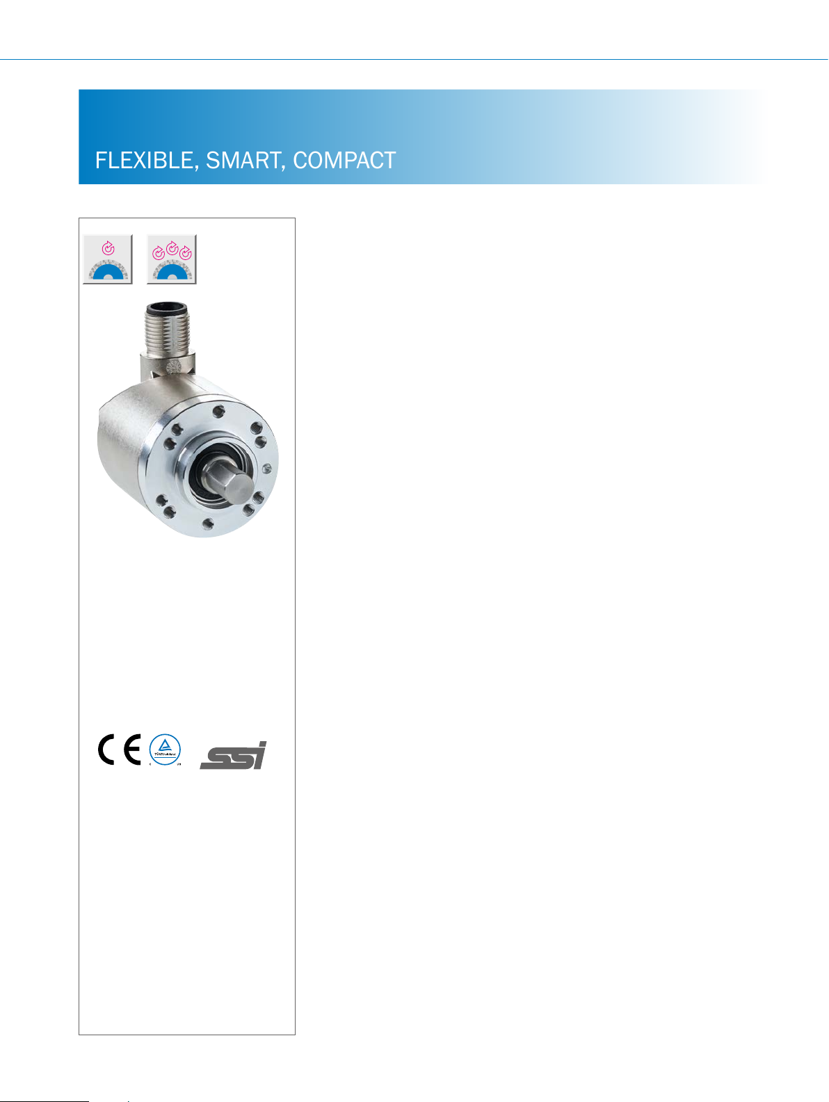
AHS/AHM36 SSI ABSOLUTE ENCODERS
FLEXIBLE, SMART, COMPACT
Product description
The AHS/AHM36 SSI absolute encoder
product family provides increased exibility due to its mechanical adaptation,
electrical connectivity, and SSI communication. With their rotating male connector or cable outlets as well as the various
mounting hole patterns and adapter
anges, these encoders are suitable for
nearly any application. The encoders are
able to connect to a wide range of controls due to a programming tool that can
be used to make individual adjustments
to the structure of the SSI protocol, in
addition to adjusting the singleturn/multiturn resolution, the counting direction,
and other parameters. Thanks to the
large operating temperature range from
–40 °C ... +100 °C and the protection
class up to IP67, this encoder family can
be used in harsh ambient conditions.
The rugged, reliable, fully magnetic sensor system provides a maximum resolution of 14 bits for the singleturn variant
and 26 bits for the multiturn variant.
G
1)
1)
UL 508 compliant.
More information
Fields of application . . . . . . . . . . .G-233
Detailed technical data. . . . . . . . .G-233
Type code. . . . . . . . . . . . . . . . . . . .G-236
Ordering information. . . . . . . . . . .G-238
Dimensional drawings . . . . . . . . .G-239
Proposed tting . . . . . . . . . . . . . . .G-242
PIN assignment. . . . . . . . . . . . . . .G-244
Singleturn signal outputs .......G-245
Multiturn signal outputs ........G-247
Recommended accessories. . . . .G-249
At a glance
• Compact 36 mm absolute encoder
with max. 26 bits (singleturn: 14 bits,
multiturn: 12 bits)
• Face mount ange, servo ange, blind
hollow shaft
• Rotating M12 male connector or
rotating cable outlet
• SSI interface
Your benets
• Simple, time-saving mechanical
installation due to a rotating male
connector or cable outlet, various
mounting hole patterns, and many
different shafts
• Simple and exible electrical installa-
tion with various conguration options
and adjustable SSI protocol structure
(programmable SSI version)
• Programmable SSI version: Resolu-
tion, preset value, etc. can be programmed (depending on the type)
• Protection class up to IP67 (depend-
ing on the type)
• Operating temperature:
–40 °C ... +100 °C (depending on
the type)
• Easy setup for various applications
allowing binary, non-binary, and
non-integer resolutions with the round
axis functionality (programmable SSI
version)
• Reliable operation in harsh environ-
ments thanks to the rugged, reliable,
fully magnetic sensor system
• Space-efcient and cost-effective
design that is suitable for applications
where space is tight
• High performance at a cost-efcient
price
G-232
ENCODERS | SICK 8015560/2015-09-01
Subject to change without notice
Page 2

Fields of application
• Measures the absolute position in various industries,
machines, and tools, including automated guided systems
(AGS), industrial trucks, commercial vehicles, packaging
Detailed technical data
Performance
Max. number of steps per revolution
Max. number of revolutions
Absolute singleturn 1
Absolute multiturn 4,096 (12 bit)
Resolution
Absolute singleturn
Non-programmable 256, 360, 512, 720, 1,024, 2,048, 3,600,
Programmable
Absolute multiturn
Non-programmable 8x12 bit, 9x12 bit, 10x12 bit, 11x12 bit,
Programmable
Error limits
Repeatability
Measuring increment (360 °/ number of
steps per revolution)
Initialization time
1)
Can be programmed using SICK programming tools.
2)
Position can be read after this period.
4,096 (12 bit) 16,384 (14 bit)
4,096
1)
– 1 ... 16,384
12x12 bit
1)
– 0x0 bit ... 14x12 bit
± 0.35° (at 20 °C)
± 0.25° (at 20 °C) ± 0.2° (at 20 °C)
± 0.09° ± 0.022°
2)
100 ms
ABSOLUTE ENCODERS AHS/AHM36 SSI
machines, logistics applications, machine construction and
medical technology
Basic Advanced
256, 360, 512, 720, 1,024, 2,048, 3,600,
4,096, 8,192, 16,384
8x12 bit, 9x12 bit, 10x12 bit, 11x12 bit,
12x12 bit, 13x12 bit, 14x12 bit
Interfaces
Electrical interface
Code type
Non-programmable Gray
Programmable – Gray, binary
Code sequence
Non-programmable CW/CCW, congurable via cable
Programmable – CW/CCW, congurable via Programming Tool
Interface signals
Max. clock frequency
Set (electronic adjustment)
CW/CCW (counting sequence when turning)
Conguration data
Position forming time
1)
Min. LOW level (Clock +) 500 ns.
Basic Advanced
SSI
or cable
Clock +, Clock -, Data +, Data-
60 kHz ... 2 MHz
H active (L = 0 ... 3 V, H = 4 ... Us V)
L active (L = 0 ... 1 V, H = 2 ... Us V)
– Number of steps per revolution, number of
125 μs
1)
revolutions (multiturn only), PRESET, counting
direction, code type, offset, position bits,
position of error bit, round axis functionality
(multiturn version only), SSI mode
G
Subject to change without notice
ENCODERS | SICK8015560/2015-09-01
G-233
Page 3

G
AHS/AHM36 SSI ABSOLUTE ENCODERS
Electrical data
Basic Advanced
Connection type
Operating voltage range
Max. power consumption without load
Reverse polarity protection
MTTFd: mean time to dangerous failure
1)
This product is a standard product and does not constitute a safety component as dened in the Machinery Directive. Calculation based on nominal load of devices, average ambient temperature 40 °C, frequency of use 8760 h/a. All electronic failures are considered hazardous. For more information, see document no.
8015532.
Mechanical data
Shaft diameter
Solid shaft 6 mm, 1/4", 8 mm, 3/8", 10 mm
Blind hollow shaft 6 mm, 1/4", 8 mm, 3/8", 10 mm
Start up torque
Solid shaft 0.5 Ncm (at 20 °C) 1 Ncm (at 20 °C)
Blind hollow shaft 0.5 Ncm (at 20 °C) 1 Ncm (at 20 °C)
Operating torque
Solid shaft < 0.5 Ncm (at 20 °C) < 1 Ncm (at 20 °C)
Blind hollow shaft < 0.5 Ncm (at 20 °C) < 1 Ncm (at 20 °C)
Permissible shaft loading
Solid shaft 40 N (radial)
Permissible shaft movement, static/dynamic
Blind hollow shaft ± 0.3 mm / ± 0.1 mm radial
Max. operating speed
Singleturn 9,000 rpm
Multiturn 6,000 rpm
Bearing lifetime
Solid shaft 3.6 x 10⁸ revolutions
Blind hollow shaft 2.0 x 10
Shaft material
Flange material
Housing material
Cable material
Mass
Solid shaft 0.12 kg (related to encoder with connector outlet)
Blind hollow shaft 0.12 kg (related to encoder with connector outlet)
1)
Take into account self-heating of 3.5 K per 1,000 revolutions/min when designing the operating temperature range.
2)
Take into account self-heating of 5.5 K per 1,000 revolutions/min when designing the operating temperature range.
3)
For Advanced type encoders, the shaft seal must be inspected regularly.
M12 male connector, 8-pin, universal
Cable, 8-wire, universal, 0.5 m
Cable, 8-wire, universal, 1.5 m
Cable, 8-wire, universal, 3 m
Cable, 8-wire, universal, 5 m
4.5 V DC ... 32 V DC
≤ 1.5 W
l
1)
230 years (EN ISO 13849-1)
Basic Advanced
20 N (axial)
± 0.3 mm / ± 0.1 mm axial
1)
1)
9
revolutions
Stainless steel
Aluminum
Zinc
PUR
6,000 rpm
6,000 rpm
2), 3)
2), 3)
G-234
ENCODERS | SICK 8015560/2015-09-01
Subject to change without notice
Page 4

ABSOLUTE ENCODERS AHS/AHM36 SSI
Basic Advanced
Rotor moment of inertia
Solid shaft 2.5 gcm²
Blind hollow shaft 15 gcm²
Max. angular acceleration
1)
Take into account self-heating of 3.5 K per 1,000 revolutions/min when designing the operating temperature range.
2)
Take into account self-heating of 5.5 K per 1,000 revolutions/min when designing the operating temperature range.
3)
For Advanced type encoders, the shaft seal must be inspected regularly.
Ambient data
EMC
Enclosure rating
Permissible relative humidity
Operating temperature range
Storage temperature range
Resistance to shocks
Resistance to vibrations
1)
In an assembled male connector.
2)
For Advanced type encoders, the shaft seal must be inspected regularly.
≤ 500,000 rad/s²
Basic Advanced
According to EN 61000-6-2 and EN 61000-6-3
IP 65 on housing side (acc. to IEC 60529)
1)
IP 65 on shaft side (acc. to IEC 60529)
90% (condensation not permitted)
–20 °C ... +70 °C –40 °C ... +100 °C
–40 °C ... +100 °C, without packaging
100 g/6 ms (according to EN 60068-2-27)
20 g/10 Hz ... 2,000 Hz (according to EN 60068-2-6)
IP 66 + IP 67, on housing side (acc.
to IEC 60529)
IP 66 + IP 67, on shaft side (acc. to
IEC 60529)
1)
2)
G
Subject to change without notice
ENCODERS | SICK8015560/2015-09-01
G-235
Page 5
AHS/AHM36 SSI ABSOLUTE ENCODERS
Type code
Singleturn
Type
B Basic
A Advanced
Mechanical design
B A Blind hollow shaft, 6 mm
B B Blind hollow shaft, 8 mm
B C Blind hollow shaft, 3/8"
B D Blind hollow shaft, 10 mm
B K Blind hollow shaft, 1/4"
S 1 Solid shaft, servo ange, 6x12 mm
S 9 Solid shaft, servo ange, 8x12 mm
S 2 Solid shaft, servo ange, 10x12 mm
S A Solid shaft, servo ange, 1/4"x12 mm
S B Solid shaft, servo ange, 3/8"x12 mm
S 3 Solid shaft, face mount ange, 6x12 mm
S 5 Solid shaft, face mount ange, 8x12 mm
S 4 Solid shaft, face mount ange, 10x12 mm
S 8 Solid shaft, face mount ange, 1/4"x12 mm
S 7 Solid shaft, face mount ange, 3/8"x12 mm
S C Solid shaft, face mount ange, 10x24 mm, for use with the adapters 2072298 and 2072295
1)
Electrical interface
A 4,5 … 32 V, SSI, gray
P 4.5 … 32 V, SSI, gray/binary, programmable (type A only)
2)
G
Connection type
C M12, 8-pin, universal
J Cable, 8-wire, universal, 0.5 m
K Cable, 8-wire, universal, 1.5 m
L Cable, 8-wire, universal, 3 m
M Cable, 8-wire, universal, 5 m
3)
3)
3)
3)
Resolution
00256 ... 04,096 Steps per revolution (type B)
00256 ... 16,384 Steps per revolution (type A)
4)
4)
A H S 3 6 - O
1)
Flange adapters can be used for additional mechanical interfaces, see Mounting suggestions.
2)
Permissible shaft load lower than gure list in technical data.
3)
NRTL certicate only valid for operating temperatures from –40 °C ... + 85 °C.
4)
Number of steps for non-programmable devices: Basic: 256, 360, 512, 720, 1,024, 2,048, 3,600, 4,096 Advanced: 256, 360, 512, 720, 1,024, 2,048, 3,600,
4,096, 8,192, 16,384. Other steps available on request. Number of steps for programmable devices (Advanced only): 16,384, programmable using Programming Tool.
G-236
ENCODERS | SICK 8015560/2015-09-01
Subject to change without notice
Page 6

Multiturn
Type
B Basic
A Advanced
ABSOLUTE ENCODERS AHS/AHM36 SSI
Mechanical design
B A Blind hollow shaft, 6 mm
B B Blind hollow shaft, 8 mm
B C Blind hollow shaft, 3/8"
B D Blind hollow shaft, 10 mm
B K Blind hollow shaft, 1/4"
S 1 Solid shaft, servo ange, 6x12 mm
S 9 Solid shaft, servo ange, 8x12 mm
S 2 Solid shaft, servo ange, 10x12 mm
S A Solid shaft, servo ange, 1/4"x12 mm
S B Solid shaft, servo ange, 3/8"x12 mm
S 3 Solid shaft, face mount ange, 6x12 mm
S 5 Solid shaft, face mount ange, 8x12 mm
S 4 Solid shaft, face mount ange, 10x12 mm
S 8 Solid shaft, face mount ange, 1/4"x12 mm
S 7 Solid shaft, face mount ange, 3/8"x12 mm
S C Solid shaft, face mount ange, 10x24 mm, for use with the adapters 2072298 and 2072295
S D Solid shaft, servo ange, 6x12 mm for adapting to 1.25 m Ecoline wire draw mechanism
1)
5)
Electrical interface
A 4,5 … 32 V, SSI, gray
P 4.5 … 32 V, SSI, gray/binary, programmable (type A only)
2)
Connection type
C M12, 8-pin, universal
J Cable, 8-wire, universal, 0.5 m
K Cable, 8-wire, universal, 1.5 m
L Cable, 8-wire, universal, 3 m
M Cable, 8-wire, universal, 5 m
3)
3)
3)
3)
Resolution
8x12 … 12x12 bit (Type B)
8x12 … 14x12 bit (Type A)
4)
4)
A H M 3 6 - O
1)
Flange adapters can be used for additional mechanical interfaces, see Mounting suggestions from page 17.
2)
Permissible shaft load lower than gure list in technical data.
3)
NRTL certicate only valid for operating temperatures from –40 °C ... + 85 °C.
4)
Resolution for non-programmable devices: Basic: 8x12, 9x12, 10x12, 11x12, 12x12. Advanced: 8x12, 9x12, 10x12, 11x12, 12x12, 13x12, 14x12. Other resolutions
on request. Resolution for programmable devices (Advanced only): 14x12, programmable using Programming Tool.
5)
Protection class on shaft side always IP65.
G
Subject to change without notice
ENCODERS | SICK8015560/2015-09-01
G-237
Page 7

AHS/AHM36 SSI ABSOLUTE ENCODERS
Ordering information
Absolute singleturn, solid shaft, servo ange
• Electrical interface: SSI
Shaft diameter Connection type Number of steps Resolution Programmable Type Part no.
6 x 12 mm
6 x 12 mm
M12 male connec-
tor, 8-pin, universal
M12 male connec-
tor, 8-pin, universal
Cable, 8-wire,
universal, 1.5 m
4,096 4,096 x 1 –
≤ 16,384 16,384 x 1
≤ 16,384 16,384 x 1
l
l
Absolute multiturn, solid shaft, servo ange
• Electrical interface: SSI
Shaft diameter Connection type Number of steps Resolution Programmable Type Part no.
6 x 12 mm
6 x 12 mm
M12 male connec-
tor, 8-pin, universal
M12 male connec-
tor, 8-pin, universal
Cable, 8-wire,
universal, 1.5 m
4,096 4,096 x 4,096 –
≤ 16,384 16,384 x 4,096
≤ 16,384 16,384 x 4,096
l
l
AHS36B-
S1AC004096
AHS36A-
S1PC016384
AHS36A-
S1PK016384
AHM36B-
S1AC012x12
AHM36A-
S1PC014x12
AHM36A-
S1PK014x12
1066017
1066014
1066013
1066012
1066009
1066008
G
Absolute singleturn, solid shaft, face mount ange
• Electrical interface: SSI
Shaft diameter Connection type Number of steps Resolution Programmable Type Part no.
8 x 12 mm
M12 male connec-
tor, 8-pin, universal
16,384 16,384 x 1 –
AHS36A-
S5AC016384
1067269
Absolute multiturn, solid shaft, face mount ange
• Electrical interface: SSI
Shaft diameter Connection type Number of steps Resolution Programmable Type Part no.
6 x 12 mm
M12 male connec-
tor, 8-pin, universal
Cable, 8-wire,
universal, 1.5 m
≤ 16,384 16,384 x 4,096
≤ 16,384 16,384 x 4,096
l
l
AHM36A-
S3PC014x12
AHM36A-
S3PK014x12
1066007
1066006
Absolute singleturn, blind hollow shaft
• Electrical interface: SSI
Shaft diameter Connection type Number of steps Resolution Programmable Type Part no.
6 mm
M12 male connec-
tor, 8-pin, universal
Cable, 8-wire,
universal, 1.5 m
≤ 16,384 16,384 x 1
≤ 16,384 16,384 x 1
l
l
AHS36A-
BAPC016384
AHS36A-
BAPK016384
1066016
1066015
G-238
ENCODERS | SICK 8015560/2015-09-01
Subject to change without notice
Page 8

ABSOLUTE ENCODERS AHS/AHM36 SSI
X = Measuring point for operating temperature
11.8 (0.46)
5.8
(0.23)
X = Measuring point for operating temperature
Absolute multiturn, blind hollow shaft
• Electrical interface: SSI
Shaft diameter Connection type Number of steps Resolution Programmable Type Part no.
M12 male con-
6 mm
nector,
8-pin, universal
Cable, 8-wire,
universal, 1.5 m
≤ 16,384 16,384 x 4,096
≤ 16,384 16,384 x 4,096
Dimensional drawings (dimensions in mm)
Solid shaft, servo ange, M12 male connector
11.4
(0.45)
5.8 (0.23)
B
B
0.02
2.5
(0.08)
(0.10)
0.08
0.08
B
+0.15
2.5 (0.10)
2
12 ±0.3
Ø D f7
(0.47)
11.5
(0.45)
A
X
–0.025
–0.064
H
Ø 33 (1.30)
B
–0.025
–0.064
Ø 33 (1.30)
34.2 (1.35)
+0.3
–0.1
Ø 36 (1.41)
45°
4 x 90° = 360°
14.5 (0.57)
M12 x 1
M3 x 5
(4 x)
26 ±0.05 (1.02)
l
l
Ø 0.05
A
AHM36A-
BAPC014x12
AHM36A-
BAPK014x12
60 (2.36)
1066011
1066010
11.8 (0.46)
0.03
B
0.03
B
43 (1.69)
Solid shaft, servo ange, cable output
2.5 (0.10)
+0.15
Ø 2.5
(0.10)
12
±0.3 (0.47)
2 (0.08)
11.5
A
Ø D f7
(0.45)
X
H
B0.02
–0.025
–0.064
Ø 33 (1.30)
0.03
B
B0.03
Bend radius of cable; R = 30 mm
0.08
B
0.08
B
B
43
(1.69)
2.6
(0.10)
2.6
(0.10)
B
(0.57)
14.5
45°
61
(2.40)
A
Ø 0.05
M3 x 5
35.9 (1.41)
–0.1
Ø 36 (1.41)
4 x 90° = 360°
B
(4 x)
±0.05 (1.02)
Ø 26
G
Subject to change without notice
ENCODERS | SICK8015560/2015-09-01
G-239
Page 9

AHS/AHM36 SSI ABSOLUTE ENCODERS
2.5
11.4
11.4
14.5
(0.46)
11.8
(0.46)
14.5
(0.57)
5.8
Solid shaft, servo ange, for adapting to 1.25 m Ecoline wire draw mechanism, SD mechanical design
0.02
(0.10)
+0.15
2.5
(0.15 +0.01)
1.6
(0.06)
12 ±0.3
(0.01)
0.08
0.08
A
(0.45)
5.8
(0.23)
A
A
X
A
43
(1.69)
2.6
(0.10)
+0.3
-0.1
Ø 36
(1.42)
-0.004
0.03
-0.012
Ø 6 g6 ( )
-0,025
-0.064
(1.30
Ø 33 f8 ( )
0.03
-0.006
(0.24)
A
A
-0.031
2 p9 ( )
Solid shaft, face mount ange, M12 male connector
(0.45)
5.8
(0.23)
34.2
-0.1
+0.3
(1.42)
Ø 36
0.02
12 ±0.3
(0.47)
11.5
ØD f7
(0.45)
A
H
B
-0.02
-0.05
(0.79)
Ø 20
5
(0.2)
X
B
34.2
(1.35)
(1.35)
3 x 120° = 360°
4 x 90° = 360°
14.5
(0.57)
M12 x 1
M12 x 1
(0.57)
M3 x 5 (10 x)
Ø 28 ±0.05
60
(2.36)
11.8
(0.46)
Ø 0.05
A
Ø 0.05
A
(1.1)
(1.18)
Ø 30 ±0.05
60
(2.36)
11.8
G
0.03
B
0.03
B
X = Measuring point for operating temperature
43
(1.69)
(0.1)
2.6
Solid shaft, face mount ange, cable output
(0.23)
12 ±0.3 (0.47)
11.5
(0.45)
B0.02
X
A
H
–0.02
–0.05
Ø D f7
Ø 20 (0.79)
0.03
B
B0.03
X = Measuring point for operating temperature
Bend radius of cable; R = 30 mm
5
(0.20)
B
2.6
(1.69)
(0.10)
43
+0.3
–0.1
Ø 36 (1.41)
3 x 120° = 360°
35.9 (1.41)
4 x 90° = 360°
B
3 x 120° = 360°
M3 x 5
(10 x)
3 x 120° = 360°
A
Ø 0.05
Ø 0.05
Ø 28 ±0.05 (1.10)BØ 30 ±0.05 (1.18)
61
A
(2.3640)
G-240
ENCODERS | SICK 8015560/2015-09-01
Subject to change without notice
Page 10

Blind hollow shaft, M12 male connector
14.5 (0.57)
11.8 (0.46)
X = Measuring point for operating temperature
11.8 (0.46)
5.8 (0.23)
11.4 (0.45)
(0.31)
8
3.25
(0.13)
5.8 (0.23)
M12 x 1
ABSOLUTE ENCODERS AHS/AHM36 SSI
67.6
(2.66)
X
–0.1
Ø D f7
Ø 38.6 (1.52)
+0,2
Ø 20 (0.79)
51 (2.01)
2.6
(0.10)
34.2 (1.35)
+0.3
–0.1
Ø 36 (1.42)
±0.05 (0.12)
3.1
(2.05)
Ø 52
Ø46
Ø 40
±0.1 (1.81)
±0.1 (1.57)
max. Ø 24 (0.94)
12
(0.47)
Customer’s own shaft: insertion depth of at least 15 mm to max. of 22 mm, from contact surface, from stator coupling, recommended shaft tolerance of k7
Blind hollow shaft, cable outlet
14.5 (0.57)
8
(0.31)
3.25
(0.13)
X
–0.1
Ø D f7
Ø 38.6 (1.52)
+0.2
Ø 20 (0.79)
X = Measuring point for operating temperature
51 (2.01)
2.6
(0.10)
35.9 (1.42)
±0.05 (0.12)
3.1
+0.3
–0.1
Ø 36 (1.42)
Ø 52
(2.05)
Ø46
±0.1 (1.81)
Ø 40
±0.1 (1.57)
(0.94)
12
max. Ø 24
Bend radius of cable; R = 30 mm
Customer’s own shaft: insertion depth of at least 15 mm to max. of 22 mm, from contact surface, from stator coupling, recommended shaft tolerance of k7
69 (2.72)
G
Subject to change without notice
ENCODERS | SICK8015560/2015-09-01
G-241
Page 11

AHS/AHM36 SSI ABSOLUTE ENCODERS
M12 x 1
(0.46)
11.4
4
+0.1
11.4
(0.46)
11.4
(0.46)
M12 x 1
Ø 6 f7
-0.010
Proposed tting
Solid shaft, face mount ange with ange adapter, centering hub D20 to D50 (BEF-FA-020-050, 2072297)
(0.16)
3
0.02
B
10 ±0.3
(0.39)
(0.12)
A
X
5.4
(0.21)
-0.025
-0.064
(2.03)
(1.97)
51.5-0.2
Ø 50 f8
0.03
B
0.03
B
10
(0.39)
B
+0.1
X = Measuring point for operating temperature
Sample order for 6 mm shaft diameter: AHx36x-S3xx0xxxxx + BEF-FA-020-050 (adapter is not pre-assembled)
Solid shaft, face mount ange with ange adapter, centering hub D20 to D36 (BEF-FA-020-036, 2072298)
(1.77)
(0.45)
5.8
(0.23)
Ø 0.05
A
120° (3 x)
-0.010
-0.022
34.2
(1.35)
(0.24)
(1.42)
Ø 42 ±0.05
(1.65)
Ø 6 f7
3 x M4 3.6
Ø 58
(2.28)
(0.14)
-0.1
+0.3
Ø 36
2.6
(0.1)
45
62
(2.44)
11.8
14
(0.55)
(0.75)
18
(0.71)
+0.1
8
(0.31)
X
B
0.02
B
19 ±0.3
A
-0.013
-0.028
(0.39)
Ø 10 f7
-0.025
-0.064
9
(1.42)
(0.35)
Ø 36 f8
0.03
(0.45)
5.8
(0.23)
B
34.2
(1.35)
120° (3 x)
-0.1
+0.3
(1.42)
-0.1
(2.12)
Ø 53.8
Ø 36
25°
M12 x 1
3 x M4
Ø 48 ±0.05
(1.89)
Ø 0.05
A
65
(2.56)
11.8
G
0.03
B
0.03
B
X = Measuring point for operating temperature
Sample order for 10 mm shaft diameter: AHx36x-SCxx0xxxxx + BEF-FA-020-036 (adapter is not pre-assembled)
Solid shaft, face mount ange with ange adapter, centering hub D20 to D36, 2 mm high (BEF-FA-020-036-002, 2072296)
12 ±0.3
(0.47)
11.5
(0.45)
X
-0.022
Sample order for 6 mm shaft diameter: AHx36x-S3xx0xxxxx + BEF-FA-020-036-002 (adapter is not pre-assembled)
A
(0.12)
3
(0.24)
5.4
0.03
0.03
0.03
(0.21)
B
B
B
X = Measuring point for operating temperature
(0.12)
3
(1.89)
2.6
(0.1)
48
(0.45)
5.8
(0.23)
Ø 0.1
B
34.2
(1.35)
6
(0.24)
Ø 59.5
(2.34)
120° (3 x)
60
(2.36)
B
(0.1)
-0.1
+0.3
(1.42)
Ø 36
2.6
Ø 30 ±0.05
(1.18)
3 x M3
3.6
(0.14)
-0.02
-0.05
(0.79)
Ø 20
11.8
G-242
ENCODERS | SICK 8015560/2015-09-01
Subject to change without notice
Page 12

ABSOLUTE ENCODERS AHS/AHM36 SSI
11.4
(0.46)
M12 x 1
Ø 6 f7
-0.010
(0.46)
11.4
Ø 36.5
M12 x 1
Solid shaft, face mount ange with ange adapter, centering hub D20 to D24 (BEF-FA-020-024, 2072294)
12 ±0.3
(0.47)
11.5
(0.45)
X
-0.022
(0.24)
A
B
5.4
(0.21)
0.03
B
0.03
B
0.03
B
(0.12)
3
(0.45)
2.6
(0.1)
5.8
(0.23)
Ø 0.1
B
34.2
(1.35)
-0.1
+0.3
(1.42)
Ø 36
Ø 30 ±0.05
(1.18)
3 x M3
3.6
(0.14)
120° (3 x)
-0.02
-0.05
(0.79)
Ø 20
X = Measuring point for operating temperature
Sample order for 6 mm shaft diameter: AHx36x-S3xx0xxxxx + BEF-FA-020-024 (adapter is not pre-assembled)
Solid shaft, face mount ange with ange adapter, centering hub D20 to D30 (BEF-FA-020-030, 2072295)
(0.45)
5.8
(0.23)
Ø 0.1
A
34.2
(1.35)
B
-0.1
+0.3
(1.42)
Ø 36
Ø 24
(0.94)
9
(0.35)
90° (4 x)
Ø 10 h11
(0.39)
(1.44)
Ø 30 ±0.05
(1.18)
0.03
B
A
17
(0.67)
X
(0.16)
4
(0.16)
4
Ø 30
(1.18)
(2.36)
(2.64)
60
11.8
67
11.8
4
0.03 0.03
(0.16)
B
2.6
(0.1)
B
M4 (4 x)
G
X = Measuring point for operating temperature
Sample order for 10 mm shaft diameter: AHx36x-SCxx0xxxxx + BEF-FA-020-030 (adapter is not pre-assembled)
Subject to change without notice
ENCODERS | SICK8015560/2015-09-01
G-243
Page 13

AHS/AHM36 SSI ABSOLUTE ENCODERS
PIN assignment
View of M12 male device connector on encoder
G
PIN, 8-pin,
M12 male
connector
1Brown Data- Interface signals
2White Data+ Interface signals
3Black
4PinkSET Electronic adjustment
5YellowClock+ Interface signals
6Lilac Clock– Interface signals
7BlueGND Ground connection
8Red +USOperating voltage
Screen Screen Screen
R¯/VForwards / Reverse: This input programs the counting direction for the
encoder. When it is not connected, this input is set to HIGH. If the encoder
shaft is rotated clockwise (to the right) as viewed when facing the shaft, it
counts in ascending order. If it should count in ascending order when the
shaft is rotated counterclockwise (to the left), then this connection must be
permanently set to LOW level (GND).
SET This input is for electronic zeroing. If the SET cable is set to US for more
than 250 ms, the mechanical position corresponds to the O value, i. e., the
predetermined SET value.
Wire colors,
cable outlet
Signal Explanation
Sequence for direction of rotation
R¯/V
Screen connected to housing
on encoder side. Connected to
ground on control side.
G-244
ENCODERS | SICK 8015560/2015-09-01
Subject to change without notice
Page 14

ABSOLUTE ENCODERS AHS/AHM36 SSI
Clock +
Bi
B
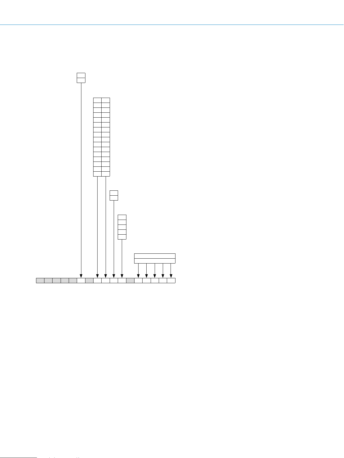
Singleturn signal outputs
Singleturn SSI data format
Cycle 1–14: position bits
Cycle 15: errorbit
LSB
Singleturn
ERROR
t
12345678910 11 12 13 14 15
13 12 11 10 9 8765 43210
MS
Non-programmable encoder
Non-programmable encoders always output the SSI position MSB-justied (left-justied).
• 14 bits + 1 errorbit are always output (irrespective of the type and resolution selected)
• For resolutions below 14 bits, non-assigned bits are lled with 0.
Programmable encoder
• Per default, programmable encoders output the SSI position MSB-justied (left-justied).
• The operating modes “binary” and “non-binary” can be selected to set the resolution.
• All formats (left and right-justied) can be covered by shifting the bits in the programming interface accordingly using the arrow
keys.
Errorbit
ERROR: general error This bit is set as soon as an error occurs in the encoder. This bit remains set as long as the error is present.
In non-programmable encoders, the errorbit is always output as the 15th bit. In programmable encoders, it can also be output as
the 15th bit or can be transmitted directly after the position bits.
The evaluation of the errorbit must be implemented in the control unit.
The errorbit output need not be used by the control unit.
If the errorbits cannot be evaluated in the control unit, the control unit must be set to the encoder resolution.
The errorbits must then be masked out at the control.
SSI mode:
Non-programmable encoders work in asynchronous SSI mode.
In programmable encoders, the programming interface enables users to choose between asynchronous and synchronous SSI
mode. Asynchronous SSI mode is selected as the default setting.
Asynchronous SSI mode:
The position is always formed and made available every 125 µs. The time for calculating the position is not related to the master
clock. In asynchronous SSI mode, the break between two clock bursts must remain constant with a maximum deviation of ± 20%
and must not exceed 600 ms.
Synchronous SSI mode:
The position is formed in sync with the master clock output, i.e., the time of the position values is related to the time of the master
clock.
The position formation process begins 20 µs following the end of a clock burst. The position is then made available after 125 µs.
The next position is formed a further 20 µs after the end of the subsequent clock burst. The break between two clock bursts must
be at least 150 µs.
G
Subject to change without notice
ENCODERS | SICK8015560/2015-09-01
G-245
Page 15

AHS/AHM36 SSI ABSOLUTE ENCODERS
Programming interface and legend
Operating mode: binary
Operating mode: non binary
G
G-246
ENCODERS | SICK 8015560/2015-09-01
Subject to change without notice
Page 16

ABSOLUTE ENCODERS AHS/AHM36 SSI
Clock
Bi
Multiturn signal outputs
Multiturn SSI data format
+
12345678910 11 1213 1415 16 1718 19 20 21 22 2324 25 2627
t
MSB
1415 13 12 11 10 987654321016171819202122232425
SingleturnMultiturn
ERROR
LSB
Non-programmable encoder
Non-programmable encoders always output the SSI position MSB-justied (left-justied).
• For non-programmable multiturn encoders, the number of revolutions is set to a xed 4,096 (12 bits).
• 26 bits + 1 errorbit are always output (irrespective of the type and resolution selected).
For resolutions below 26 bits, non-assigned bits are lled with 0.
Programmable encoder
• Per default, programmable encoders output the SSI position MSB-justied (left-justied).
• The operating modes “binary”, “non-binary” and “round axis functionality” can be selected to set the resolution.
• All formats (left and right-justied, 25 bit mode and r-tree format) can be covered by shifting the bits in the programming inter-
face accordingly using the arrow keys.
Errorbit
ERROR: general error This bit is set as soon as an error occurs in the encoder. This bit remains set as long as the error is present.
In non-programmable encoders, the errorbit is always output as the 27th bit. In programmable encoders, it can also be output as
the 27th bit or can be transmitted directly after the position bits.
Cycle 1-12: multiturn position bits
Cycle 13-26: singleturn position bits
Cycle 27: errorbit
The evaluation of the errorbit must be implemented in the control unit.
The errorbit output need not be used by the control unit.
If the errorbits cannot be evaluated in the control unit, the control unit must be set to the encoder resolution.
The errorbits must then be masked out at the control.
SSI mode:
Non-programmable encoders work in asynchronous SSI mode.
In programmable encoders, the programming interface enables users to choose between asynchronous and synchronous
SSI mode. Asynchronous SSI mode is selected as the default setting.
Asynchronous SSI mode:
The position is always formed and made available every 125 µs. The time for calculating the position
is not related to the master clock. In asynchronous SSI mode, the break
between two clock bursts must remain constant with a maximum deviation of ± 20% and
must not exceed 600 ms.
Synchronous SSI mode:
The position is formed in sync with the master clock output, i.e., the time of the position values
is related to the time of the master clock.
The position formation process begins 20 µs following the end of a clock burst. The position is then
made available after 125 µs. The next position is formed a further 20 µs after the end of the subsequent
clock burst. The break between two clock bursts must be at least 150 µs.
G
Subject to change without notice
ENCODERS | SICK8015560/2015-09-01
G-247
Page 17

AHS/AHM36 SSI ABSOLUTE ENCODERS
Round axis functionality
The programmable multi-turn encoder supports the gear functions for rotary axes (endless shaft). Here, the number of revolutions
is set a break; a total number of steps is also set. The total number of steps is distributed over the set number of revolutions, e. g.
100 steps to 12.5 revolutions (see example for the programming interface on the next page).
The round axis functionality can be used to implement a number for the overall resolution that is not a 2n multiple of the number
of steps per revolution. It is also possible to set a non-integer number both for the number of revolutions and for the number of
steps per revolution.
Programming interface and legend
Operating mode: binary
G
Operating mode: non binary
Operating mode: rotary axis
G-248
ENCODERS | SICK 8015560/2015-09-01
Subject to change without notice
Page 18

ABSOLUTE ENCODERS AHS/AHM36 SSI
Recommended accessories
Mounting systems
Mounting brackets and plates
Mounting bracket
Figure Brief description Type Part no.
Mounting bracket for encoder with centering hub 20 mm, including mounting kit for face
mount ange
Dimensional drawings g page K-725
BEF-WF-20 2066393
Flanges
Figure Brief description Type Part no.
Stator coupling on hole circle 63 mm BEF-DS08 2072206
Flange adapter centering hub D20 to D24 BEF-FA-020-024 2072294
Flange adapter centering hub D20 to D30 BEF-FA-020-030 2072295
Flange adapter centering hub D20 to D36 BEF-FA-020-036 2072298
Flange adapter centering hub D20 to D36, 2 mm high BEF-FA-020-036-002 2072296
Flange adapter centering hub D20 to D50 BEF-FA-020-050 2072297
Dimensional drawings g page K-725
Other mounting accessories
Measuring wheels and measuring wheel systems
G
Figure Brief description Type Part no.
Measuring wheel with O-ring (NBR70) for 6 mm solid shaft, circumference 200 mm BEF-MR006020R 2055222
Measuring wheel with O-ring (NBR70) for 6 mm solid shaft, circumference 300 mm BEF-MR006030R 2055634
O-ring for measuring wheels (circumference 200 mm) BEF-OR-053-040 2064061
O-ring for measuring wheels (circumference 300 mm) BEF-OR-083-050 2064076
Dimensional drawings g page K-725
Servo clamps
Figure Brief description Type Part no.
Servo clamps, small, for servo ange (clamps, eccentric fastener), 3 pcs., without
mounting material
Dimensional drawings g page K-725
Subject to change without notice
BEF-WK-RESOL 2039082
ENCODERS | SICK8015560/2015-09-01
G-249
Page 19

G
AHS/AHM36 SSI ABSOLUTE ENCODERS
Shaft adaptation
Shaft couplings
Figure Brief description Type Part no.
Bellows coupling, shaft diameter 6 mm / 6 mm, maximum shaft offset: radial
± 0.25 mm, axial ± 0.4 mm, angular ± 4°; max. speed 10,000 rpm, –30 °C ... +120 °C,
max. torque 80 Ncm; material: stainless steel bellows, aluminum hub
Bellows coupling, shaft diameter 6 mm / 10 mm, maximum shaft offset: radial
± 0.25 mm, axial ± 0.4 mm, angular ± 4°; max. speed 10,000 rpm, –30 °C ... +120 °C,
max. torque 80 Ncm; material: stainless steel bellows, aluminum hub
Bellows coupling, shaft diameter 10 mm/10 mm; maximum shaft offset: radial
± 0.25 mm, axial ± 0.4 mm, angular ± 4°; max. revolutions 10,000 rpm,
–30 °C ... +120 °C, max. torque 80 Ncm; material: stainless steel bellows, aluminum
clamping hubs
Bellows coupling, shaft diameter 10 mm/12 mm; maximum shaft offset: radial
± 0.25 mm, axial ± 0.4 mm, angular ± 4°; max. revolutions 10,000 rpm,
–30 °C ... +120 °C, max. torque 80 Ncm; material: stainless steel bellows, aluminum
clamping hubs
Double-loop coupling, shaft diameter 6 mm/10 mm, maximum shaft offset: radial
± 2.5 mm, axial ± 3 mm, angular ± 10°; max. speed 3,000 rpm, –30 °C ... +80 °C,
max. torque 1.5 Nm; material: polyurethane, galvanized steel ange
Double-loop coupling, shaft diameter 8 mm/10 mm, maximum shaft offset: radial
± 2.5 mm, axial +/-± 3 mm, angular ± 10°; max. speed 3,000 rpm, –30 °C ... +80 °C,
max. torque 1.5 Nm; material: polyurethane, galvanized steel ange
Double-loop coupling, shaft diameter 10 mm/10 mm, maximum shaft offset: radial
± 2.5 mm, axial ± 3 mm, angular ± 10°; max. speed 3,000 rpm, –30 °C ... +80 °C,
max. torque 1.5 Nm; material: polyurethane, galvanized steel ange
Double-loop coupling, shaft diameter 10 mm/12 mm, maximum shaft offset: radial
± 2.5 mm, axial ± 3 mm, angular ± 10°; max. speed 3,000 rpm, –30 °C ... +80 °C,
max. torque 1.5 Nm; material: polyurethane, galvanized steel ange
Spring washer coupling, shaft diameter 6 mm/10 mm, maximum shaft offset: radial
± 0.3 mm, axial ± 0.4 mm, angular ± 2.5°; max. speed 12,000 rpm, –10 °C ... +80 °C,
max. torque 60 Ncm; material: aluminum ange, ber-glass reinforced polyamide mem-
brane and tempered steel coupling pin
Spring washer coupling, shaft diameter 10 mm / 10 mm, maximum shaft offset: radial
± 0.3 mm, axial ± 0.4 mm, angular ± 2.5°; max. speed 12,000 rpm, –10 °C ... +80 °C,
max. torque 60 Ncm; material: aluminum ange, glass ber-reinforced polyamide mem-
brane and hardened steel coupling pin
Dimensional drawings g page K-725
KUP-0606-B 5312981
KUP-0610-B 5312982
KUP-1010-B 5312983
KUP-1012-B 5312984
KUP-0610-D 5326697
KUP-0810-D 5326704
KUP-1010-D 5326703
KUP-1012-D 5326702
KUP-0610-F 5312985
KUP-1010-F 5312986
Connectivity
Plug connectors and cables
Connecting cables with female connector
Figure Brief description Length
of
cable
2 m DOL-1208-G02MAC1 6032866
Head A: female connector, M12, 8-pin, straight
Head B: cable
Cable: suitable for drag chain, PVC, shielded, 4 x 2 x 0.25 mm², Ø 7.0 mm
Dimensional drawings g page K-725
5 m DOL-1208-G05MAC1 6032867
10 m DOL-1208-G10MAC1 6032868
20 m DOL-1208-G20MAC1 6032869
Female connectors (ready to assemble)
Figure Brief description Type Part no.
Head A: female connector, M12, 8-pin, straight, A encoded, shielded, for cable diameter
4 mm ... 8 mm
Head B: -
Operating temperature: –40 °C ... +85 °C
G-250
ENCODERS | SICK 8015560/2015-09-01
Type Part no.
DOS-1208-GA01 6045001
Subject to change without notice
Page 20

ABSOLUTE ENCODERS AHS/AHM36 SSI
Dimensional drawings g page K-725
Male connectors (ready to assemble)
Figure Brief description Type Part no.
Head A: male connector, M12, 8-pin, straight, A encoded, shielded, for cable diameter
4 mm ... 8 mm
Head B: -
Operating temperature: –40 °C ... +85 °C
Head A: male connector, M23, 12-pin, straight, shielded, for cable diameter
5.5 mm ... 10.5 mm
Head B: -
Operating temperature: –20 °C ... +130 °C
Dimensional drawings g page K-725
Cables (ready to assemble)
STE-1208-GA01 6044892
STE-2312-G 6027537
Figure Brief description Length
Head A: cable
Head B: cable
Cable: suitable for drag chain, PUR, halogen-free, shielded, 4 x 2 x 0.15 mm²,
Ø 5.6 mm
Head A: cable
Head B: cable
Cable: suitable for drag chain, PUR, halogen-free, shielded, UV and saltwater-resistant, 4 x 2 x 0.25 mm² + 2 x 0.5 mm² + 2 x 0.14 mm², Ø 7.8 mm
Dimensional drawings g page K-725
Connection cables with female and male connector
Figure Brief description Length
Head A: female connector, M12, 8-pin, straight
Head B: male connector, D-Sub, 9-pin, straight
Cable: PUR, halogen-free, shielded, 4 x 2 x 0.15 mm²
Dimensional drawings g page K-725
Other accessories
Programming and conguration tools
Type Part no.
of
cable
LTG-2308-MWENC 6027529
By the
meter
LTG-2612-MW 6028516
Type Part no.
of
cable
0.5 m DSL-2D08-G0M5AC2 2048439
G
Figure Brief description Type Part no.
Programming unit USB, for programmable SICK encoders AFS60, AFM60, DFS60,
VFS60, DFV60 and wire draw encoders with programmable encoder.
Programming unit display for programmable SICK DFS60, DFV60, AFS/AFM60, AHS/
AHM36 encoders, and wire draw encoders with DFS60, AFS/AFM60, and AHS/AHM36.
Compact dimensions, low weight, and intuitive operation.
Dimensional drawings g page K-725
- For additional accessories, please see page K-668 onwards
Subject to change without notice
PGT-08-S 1036616
PGT-10-Pro 1072254
ENCODERS | SICK8015560/2015-09-01
G-251
 Loading...