

SICK AHS36 IO-Link Inox, AHM36 IO-Link Inox, AHM36 IO-Link, AHS36 IO-Link Operating Instructions Manual
Page 1
B E T R I E B S A N L E I T U N G d e
Alle Rechte vorbehalten. Irrtümer und Änderungen vorbehalten.
1 Zu diesem Dokument
Lesen Sie diese Betriebsanleitung sorgfältig durch, bevor Sie den Encoder montie‐
ren, in Betrieb nehmen oder warten.
1.2 Funktion dieses Dokuments
Diese Betriebsanleitung leitet das qualifizierte technische Personal des Maschi‐
nenherstellers bzw. Maschinenbetreibers zur Montage, Elektroinstallation, Inbe‐
triebnahme sowie zum Betrieb und zur Wartung des Encoders an.
2 Zu Ihrer Sicherheit
AHS/AHM36 IO-Link und AHS/AHM IO-Link Inox Absolut-Encoder sind nach den
anerkannten Regeln der Technik hergestellte Messgeräte.
Der Anbau des Encoders ist von Fachpersonal mit Kenntnissen in Elektrik
und Feinmechanik vorzunehmen.
Der Encoder darf nur zu dem seiner Bauart entsprechenden Zweck verwen‐
det werden.
2.2 Grundlegende Sicherheitshinweise
Beachten Sie die für Ihr Land gültigen berufsgenossenschaftlichen Sicher‐
heits- und Unfallverhütungsvorschriften.
Schalten Sie die Spannung bei allen von der Montage betroffenen Geräte,
Maschinen und Anlagen ab.
Elektrische Verbindungen zum Encoder nie bei eingeschalteter Spannung
herstellen oder lösen, dies kann zu einem Gerätedefekt führen.
Schläge auf die Welle und Spannzange vermeiden.
3 Montage
3.1 Encoder mit Servoflansch
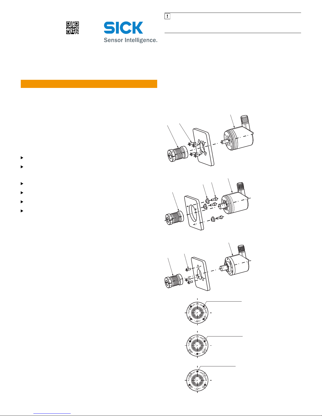
3.1.1 Anbau über flanschseitige Gewindebohrungen (Abb. 1)
Kundenseitige Antriebswelle blockieren. Kupplung (1) am Encoder (2) montieren;
darauf achten, dass diese nicht am Encoder-Flansch streift. Encoder (2) mit mon‐
tierter Kupplung (1) auf Antriebswelle aufschieben. Encoder (2) mit 4 Schrauben
M3 (3) befestigen. Kupplung (1) auf der Antriebswelle befestigen. Darauf achten,
dass die Kupplung keiner axialen Spannung ausgesetzt wird. Elektrische Verbin‐
dung bei abgeschalteter Spannung herstellen. Spannung einschalten und Funk‐
tion des Encoders prüfen.
3.1.2 Anbau mit Servoklammern (Abb. 2)
Kundenseitige Antriebswelle blockieren. Kupplung (1) am Encoder (4) montieren;
darauf achten, dass diese nicht am Encoder-Flansch streift. Servoklammern (2)
mit Schrauben M3 (3) montieren. Schrauben nicht festziehen, Servoklammern so
verdrehen, dass der Encoder-Flansch in die Zentrierung geschoben werden kann.
Encoder (4) mit montierter Kupplung (1) auf Antriebswelle und Zentrierung auf‐
schieben.
Servoklammer (2) durch Drehen in die Nut einrücken und leicht festziehen. Kupp‐
lung (1) auf Antriebswelle befestigen. Darauf achten, dass die Kupplung keiner
axialen Spannung ausgesetzt wird. Alle 3 Schrauben der Servoklammern festzie‐
hen. Elektrische Verbindung bei abgeschalteter Spannung herstellen. Spannung
einschalten und Funktion des Encoders prüfen.
3.2 Encoder mit Klemmflansch
Bei dieser Flanschausführung gibt es 2 Anbaumöglichkeiten:
•
Über flanschseitige Gewindebohrungen
•
Über Klemmung am Klemmansatz
3.2.1 Anbau über flanschseitige Gewindebohrungen (Abb. 3)
Kupplung (1) montieren; darauf achten, dass diese nicht am Encoder-Flansch
streift. Encoder (2) mit montierter Kupplung (1) auf Antriebswelle und Zentrier- /
Klemmsatz aufschieben. Encoder (2) mit 3 Schrauben M3 (3) befestigen, Kupp‐
lung (1) auf der Antriebswelle befestigen. Die Kupplung darf keinen axialen Span‐
nungen ausgesetzt werden. Elektrische Verbindung bei abgeschalteter Spannung
herstellen. Spannung einschalten und Funktion des Encoders prüfen.
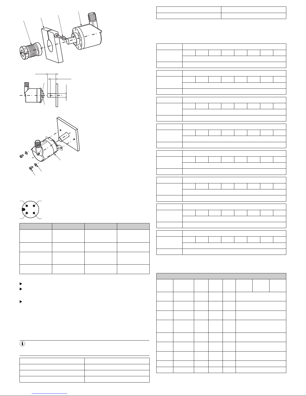
3.2.2 Anbau über den Klemmansatz (Abb. 4)
WICHTIG
Da der Klemmansatz gleichzeitig auch Zentrieransatz ist, muss die Klemm‐
vorrichtung so ausgebildet sein, dass beim Festklemmen kein unzulässiger
Winkel bzw. Wellenversatz entsteht.
Kundenseitige Antriebswelle blockieren. Kupplung (1) montieren; darauf achten,
dass diese beim Verdrehen der Welle nicht am Encoder-Flansch streift. Encoder
(4) mit montierter Kupplung (1) auf Antriebswelle und Klemmansatz in Klemmvor‐
richtung (2) aufschieben. Encoder (4) mit Schraube (3) festklemmen. Kupplung
(1) auf der Antriebswelle befestigen.
Die Kupplung darf keinen axialen Spannungen ausgesetzt werden. Elektrische
Verbindung bei abgeschalteter Spannung herstellen. Spannung einschalten und
Funktion des Encoders prüfen.
3.3 Encoder mit Flansch für Aufsteckhohlwelle (Abb. 5 und 6)
Kundenseitige Antriebswelle blockieren. Zylinderschraube (2) am Klemmring (1)
lösen. Encoder mit Spannzange auf Antriebswelle aufschieben. Anbauhin‐
weis Abb. 6 beachten! Momentenstütze (3) mit 2 Schrauben M3 (4) und U-Schei‐
ben (5) befestigen. Zylinderschraube (2) an Klemmring (1) festziehen.
Anzugsmoment max. 0,8 Nm.
Elektrische Verbindung bei abgeschalteter Spannung herstellen. Spannung ein‐
schalten und Funktion des Encoders prüfen.
1
3
2
Abbildung 1: Anbau über flanschseitige Gewindebohrungen
4
3
2
1
Abbildung 2: Anbau mit Servoklammern
1
3
2
4 x M3 auf Ø 30 mm
Tiefe 5 mm
3 x M3 auf Ø 28 mm
Tiefe 5 mm
3 x M3 auf Ø 30 mm
Tiefe 5 mm
Abbildung 3: Anbau über flanschseitige Gewindebohrung
8022049/2018-02-14/de, en AHS/AHM36 IO-Link AHS/AHM36 IO-Link Inox | SICK 1
8022049/2018-02-14
www.sick.com
AHS/AHM36 IO-Link
AHS/AHM36 IO-Link Inox
SICK AG
E
rwin-Sick
-Straße 1
D-79183 Waldkirch
Page 2
1
2
3
4
Abbildung 4: Anbau über Klemmansatz
1
2
22 max.
14,5 min.
Ø xf7
Abbildung 5: Encoder mit Flansch für Aufsteckhohlwelle (Anbauvorschlag)
3
5
4
Abbildung 6: Encoder mit Flansch für Aufsteckhohlwelle
4 Elektrische Installation
2
1 4
3
PIN Adernfarbe Signal Funktion
1 Braun L+ Versorgungsspan‐
nung Encoder 20 - 30
V (+US)
2 Weiß I/Q nicht verbunden -
keine Funktion
3 Blau L- Versorgungsspan‐
nung Encoder 0 V
(GND)
4 Schwarz C/Q IO-Link Kommunika‐
tion
4.2 Gerät elektrisch anschließen
Anschluss direkt über Rundschraubsystem M12 oder Leitungsabgang.
Der drehbare Stecker- / Leitungsabgang ist nur für die Ausrichtung des Ste‐
cker- / Leitungsabgangs während der Montage vorgesehen, nicht für dauer‐
hafte Bewegung.
Die Schutzart beim Steckerabgang wird nur mit aufgeschraubtem Gegenste‐
cker erreicht.
Anzugsmoment Gegenstecker bei M12-Steckerabgang: 1,0 Nm
4.3 IO-Link spezifische Informationen
Laden Sie das IODD-File des AHS36/AHM36 IO-Link oder AHS/AHM36 IO-Link
Inox von www.sick.com oder aus dem IODD-Finder des IO-Link Konsortiums herun‐
ter. Stellen Sie sicher, dass Sie immer das aktuelle IODD-File verwenden.
4.3.1 Physikalische Schicht
HINWEIS
Maximale Stromaufnahme des IO-Link Devices (inkl. Lastströme) darf maxi‐
malen Ausgangsstrom des Master-Ports nicht überschreiten.
SIO Modus Nein
Min. Zykluszeit 3,2 ms
Baudrate
1
COM3
Prozessdatenlänge 8 Byte
IODD Version V 1.0
Gültig für IO-Link Version 1.1.0
1
COM-Werte spezifizieren die Baudrate (s. IO-Link Spezifikation): COM1 (4,8 kbit/s),
COM2 (38,4 kbit/s), COM3 (230,4 kbit/s)
4.3.2 Prozessdaten
Record: 8 Byte
Bitoffset
Byte 0 63 62 61 60 59 58 57 56
Geschwindigkeit
Type/Subindex Integer 32
Bitoffset
Byte 1 55 54 53 52 51 50 49 48
Geschwindigkeit
Type/Subindex Integer 32
Bitoffset
Byte 2 47 46 45 44 43 42 41 40
Geschwindigkeit
Type/Subindex Integer 32
Bitoffset
Byte 3 39 38 37 36 35 34 33 32
Geschwindigkeit
Type/Subindex Integer 32
Bitoffset
Byte 4 31 30 29 28 27 26 25 24
Position
Type/Subindex Unsigned Integer 32
Bitoffset
Byte 5 23 22 21 20 19 18 17 16
Position
Type/Subindex Unsigned Integer 32
Bitoffset
Byte 6 15 14 13 12 11 10 9 8
Position
Type/Subindex Unsigned Integer 32
Bitoffset
Byte 7 7 6 5 4 3 2 1 0
Position
Type/Subindex Unsigned Integer 32
4.3.3 Servicedaten
Die folgenden ISDUs werden nicht über Data-Storage gesichert: Gerätespezifische
Markierung und roher Positionswert.
IO-Link spezifisch
Index dez
(hex)
Name Format
(Offset)
Länge Zugriff1Standard‐
wert
Wertebe‐
reich
Bemer‐
kung [Ein‐
heit]
0 (0x00) Direkte Para‐
meter 1
Record 16 Byte rw siehe IO-Link Interface Specifica‐
tion
1 (0x01) Direkte Para‐
meter 2
Record 16 Byte rw siehe IO -Link Interface Specifica‐
tion
12 (0x0C) Gerätezu‐
griffs sperren
Record 2 Byte rw
2
(0x02)
Daten‐
speiche‐
rungssperre
Bit (1) 1 Bit rw
16 (0x10) Hersteller‐
name
String 64 Byte ro SICK AG
17 (0x11) Hersteller‐
text
String 64 Byte ro SICK Sensor Intelligence
18 (0x12) Produkt‐
name
String 64 Byte ro AHx36x-xxxxxxxxxx
19 (0x13) Produkt-ID String 64 Byte ro 1xxxxxx
20 (0x14) Produkttext String 64 Byte ro Absolute Encoder Multiturn
8022049/2018-02-14/de, en AHS/AHM36 IO-Link AHS/AHM36 IO-Link Inox | SICK 2
Page 3

IO-Link spezifisch
21 (0x15) Seriennum‐
mer
String 16 Byte ro yywwnnnn
y = Jahr
w = W
oche
n = Zähler
22 (0x16) Hardware‐
v
ersion
String 64 Byte ro 1.0
23 (0x17) Firmwarever‐
sion
String 64 Byte ro 1.1.0
24 (0x18) Anwen‐
dun
gsspezi‐
fische Mar‐
kierung
String 32 Byte rw Anwendungsspezifische Markie‐
rung, beschreibbar durch Anwen‐
der
36 (0x24) Gerätestatus UInt 8 Bit ro 0 = Gerät ist OK
1 = W
artung erforderlich
2 = Außerhalb der Spezifikation
3 = Funktionsprüfung
4 = Fehler
5 ... 255 = Reserviert
40 (0x28) Prozessda‐
t
en Eingang
PD In 8 Byte ro Wie im Kapitel Prozessdaten
beschrieben, jedoch azyklisch
1
ro = nur lesen, wo = nur schreiben, rw = lesen/schreiben
SICK spezifisch
Index dez
(
hex)
Name Format
(Offset)
Länge Zugriff1Standard‐
wert
Wertebe‐
reich
Bemer‐
kung
[Einheit]
13 (0x0D) Profile Cha‐
r
acteristic
Array 8 Byte ro Unsigned
Integer16
[2]
siehe IO-Link Interface
Specification
14 (0x0E) PDInputDe‐
scr
iptor
Record 6 Byte ro siehe IO-Link Inter face Specifica‐
tion
1
(0x01)
Position Bit (24) 3 Byte ro
2
(0x02)
Geschwin‐
di
gkeit
Bit (0) 3 Byte ro
64 (0x40) Gerätespezi‐
f
ische Mar‐
kierung
String 16 Byte rw Gerätespezifische Markierung,
beschreibbar durch Anwender
65 (0x41) Geschwin‐
di
gkeit
Int 32 Bit ro
66 (0x42) Geschwin‐
di
gkeitsein‐
heit
UInt 8 Bit rw 3 0 =
Schritte
pro
Sekunde
[cps]
1 =
Schritte
pro 100
Millise‐
kunden
[cp100m
s]
2 =
Schritte
pro 10
Millise‐
kunden
[cp10ms]
3 =
Umdre‐
hungen
pro
Minute
[rpm]
4 =
Umdre‐
hungen
pro
Sekunde
[rps]
Folgende
Geschwin
digkeits‐
einheiten
können
gewählt
werden:
cps
cp100ms
cp10ms
rpm
rps
67 (0x43) Geschwin‐
di
gkeits-
Update-Zeit
UInt 32 Bit rw 2 1 ... 50 =
Bereich
der
Geschwin
digkeitsUpdateZeit
Die
UpdateZeit defi‐
niert die
Zeit zwi‐
schen den
einzelnen
Messun‐
gen [ms]
68 (0x44) Geschwin‐
di
gkeitsIntegrations‐
zeit
UInt 32 Bit rw 200 1 ... 200
= Bereich
der
Geschwin
digkeitsIntegrati‐
onszeit
Die Inte‐
grations‐
zeit defi‐
niert die
Anzahl
Werte aus
denen der
Durch‐
schnitt
berechnet
wird [ms]
81 (0x51) Schrittzahl
pr
o Umdre‐
hung
UInt 32 Bit rw 4096 1 ... 4096 = Wertebe‐
reich für Schritt zahl
pro Umdrehung
SICK spezifisch
82 (0x52)
nur
AHM36
Gesamt‐
messbereich
UInt 32 Bit rw 167772161 ... 16777216 =
Wertebereich für den
gesamten Messbe‐
reich. Der Gesamt‐
messbereich muss
das 2n-fache der Auf‐
lösung pro Umdrehung
sein
83 (0x53) Presetwert UInt 32 Bit wo 0 ... 16777215 = Preset Wertebe‐
reich
84 (0x54) Positions‐
wert
UInt 32 Bit ro
85 (0x55) Zählrichtung UInt 8 Bit rw 0 = im
Uhrzeiger‐
sinn (cw)
1 = gegen
den Uhr‐
zeigersinn
(ccw)
Die Zählrichtung
bestimmt, bei welcher
Drehrichtung sich der
Positionswert erhöht,
ausgehend von einer
Blickrichtung auf die
Welle.
86 (0x56) Roher Positi‐
onswert
UInt 32 Bit ro 0 Roher Positionswer t
ohne Offset oder Ska‐
lierungsfaktor
91 (0x5B)
nur
AHM36
Gesamt‐
messbereich
angepasst
UInt 32 Bit ro
92 (0x5C) Status Flag A UInt 16 Bit ro Zeigt das Encoder Status Flag A -
Bit kodiert
Bit_0 = Positionsfehler - Generell
beim Aufstarten
Bit_1 = Warnung - Temperatur
außerhalb zulässigem Bereich
Bit_2 = Reserviert - Immer Null
Bit_3 = Warning - Sensor-Span‐
nung außerhalb des zulässigen
Bereichs
Bit_4 = Positionsfehler - Amplitude
Multiturn außerhalb des zuläs sigen
Bereichs
Bit_5 = Warnung - Geschwindigkeit
außerhalb des zulässigen Bereichs
Bit_6 = Positionsfehler - Amplitude
des Singleturn außerhalb des
zulässigen Bereichs
Bit_7 = Eepromfehler - Ungültige
Kommunikation zum Gerät
Bit_8 ... 14 = Reserviert - Immer
Null
Bit_15 = Speicher Checksummen‐
fehler
205
(0xCD)
SICK ProfilVersion
String 4 Byte ro 1.00
1
ro = nur lesen, wo = nur schreiben, rw = lesen/schreiben
Standardkommando
Index dez
(
hex)
Zugriff1Wert Name Bemerkung [Einheit]
2 (0x02) Standard‐
k
ommando
wo 128 Gerät zurücksetzen
130 Auslieferungszu‐
s
tand wiederherstel‐
len
Erforder t Reset des
Geräts
1
ro = nur lesen, wo = nur schreiben, rw = lesen/schreiben
Fehlercodes
Code dez (hex) Additional Code Name Bemerkung [Einheit]
128 (0x80) 17 (0x11) Index nicht vorhanden Zugrif f auf einen nicht
e
xistierenden Index
128 (0x80) 18 (0x12) Subindex nicht vorhanden Zugrif f auf einen nicht
e
xistierenden Subindex
128 (0x80) 32 (0x20) Service zur Zeit nicht ver‐
f
ügbar
Auf den Parameter kann
gerade nicht zugegriffen
werden. Das Gerät erlaubt
dies im aktuellen Zustand
nicht
128 (0x80) 34 (0x22) Service zur Zeit nicht ver‐
f
ügbar - Geräte Betriebs‐
modus
Auf den Parameter kann
gerade nicht zugegriffen
werden, da sich das Gerät
zur Zeit in einem Remote
Betriebsmodus befindet
128 (0x80) 35 (0x23) Zugriff ver weigert Schreibzugriff auf einen
schr
eibgeschützten Para‐
meter
128 (0x80) 48 (0x30) Parameterwer t außerhalb
de
s gültigen Bereichs
Geschriebener Parameter‐
wert liegt außerhalb des
zulässigen Wertebereichs
128 (0x80) 51 (0x33) Parameterlänge zu groß Geschriebene Parameter‐
län
ge ist größer als erlaubt
128 (0x80) 52 (0x34) Parameterlänge zu klein Geschriebene Parameter‐
län
ge ist kleiner als
erlaubt
128 (0x80) 53 (0x35) Funktion nicht verfügbar Geschriebenes Kom‐
mando wir
d vom Gerät
nicht unterstützt
8022049/2018-02-14/de, en AHS/AHM36 IO-Link AHS/AHM36 IO-Link Inox | SICK 3
Page 4

Fehlercodes
128 (0x80) 54 (0x36) Funktion zur Zeit nicht ver‐
fügbar
Geschriebenes Kom‐
mando wird vom Gerät im
aktuellen Zustand nicht
unterstützt
128 (0x80) 65 (0x41) Inkonsistenter Parameter‐
satz
Am Ende des Blockpara‐
metertransfers wurden
Inkonsistenzen erkannt.
Der Geräteplausibilität‐
scheck schlug fehl
HINWEIS
Die Status Flag A (Index 92) in regelmäßigen Abständen auswerten, um mög‐
liche Encoder-Fehler rechtzeitig zu erkennen.
5 Bedienung
5.1 Bedien- und Anzeigeelemente
Die LED zeigt den Status des Encoders und den Kommunikationsstatus an.
LED
Statusanzeige Farbe Beschreibung
Ö
Grün Normalbetrieb - Kommunikation
O
Grün Normalbetrieb - keine Kommunikation
Ö
Orange Warnung - Kommunikation
O
Orange Warnung - keine Kommunikation
Ö
Rot Fehler - Kommunikation
O
Rot Fehler - keine Kommunikation
Ö
= blinkt
O
= leuchtet
6 Anhang
6.1 Konformitäten
8022049/2018-02-14/de, en AHS/AHM36 IO-Link AHS/AHM36 IO-Link Inox | SICK 4
Page 5

O P E R A T I N G I N S T R U C T I O N S e n
All rights reserved. Subject to change without notice.
1 About this document
Read these operating instructions carefully before you mount and commission the
Encoder.
1.2 Purpose of this document
These operating instructions provide qualified technical personnel of the machine
manufacturer or the machine operator with instructions regarding the mounting,
electrical installation, commissioning, operation, and maintenance of the
encoder.
2 Safety information
AHS/AHM36 IO-Link and AHS/AHM IO-Link Inox absolute encoders are manufac‐
tured using state-of-the-art technology.
The encoders should only be mounted by qualified personnel with electrical
and precision engineering knowledge.
The encoder may only be used for the purpose for which it was intended.
2.2 General safety notes
Observe the relevant national work safety regulations as specified by trade
associations.
During mounting, disconnect all applicable devices, machinery and systems
from the voltage.
Never connect or disconnect electrical connections to or from the encoder
when the voltage is switched on, as this may result in equipment damage.
Prevent any impact to the shaft and collet.
3 Mounting
3.1 Encoder with servo flange
3.1.1 Mounting via threaded holes on the flange side (Fig. 1)
Block the customer’s drive shaft. Mount the coupling (1) on the encoder (2);
ensure that this does not touch the encoder flange. Slide the encoder (2) together
with the mounted coupling (1) onto the drive shaft. Mount the encoder (2) using
four M3 screws (3). Mount the coupling (1) on the drive shaft. Ensure that the
coupling is not subjected to any axial stress. Establish an electrical connection
when the voltage is switched off. Switch on the voltage and check that the
encoder is functioning.
3.1.2 Mounting with servo clamps (Fig. 2)
Block the customer’s drive shaft. Mount the coupling (1) on the encoder (4);
ensure that this does not touch the encoder flange. Mount servo clamps (2) using
M3 screws (3). Do not tighten the screws; twist the servo clamps in such a way
that the encoder flange can be pushed into the center. Slide the encoder (4)
together with the mounted coupling (1) onto the drive shaft and center.
Engage the servo clamp (2) by rotating it into the slot and tighten it slightly. Mount
the coupling (1) on the drive shaft. Ensure that the coupling is not subjected to
any axial stress. Tighten all three screws on the servo clamps. Establish an electri‐
cal connection when the voltage is switched off. Switch on the voltage and check
that the encoder is functioning.
3.2 Encoder with face mount flange
There are two mounting options for this type of flange:
•
Via the threaded holes on the flange side
•
By clamping on the mounting spigot
3.2.1 Mounting via threaded holes on the flange side (Fig. 3)
Mount coupling (1); ensure that it does not touch the encoder flange. Slide the
encoder (2) together with the mounted coupling (1) onto the drive shaft and the
centering fixture/mounting spigot. Mount the encoder (2) using three M3 screws
(3) and mount the coupling (1) on the drive shaft. The coupling must not be sub‐
jected to any axial stress. Establish an electrical connection when the voltage is
switched off. Switch on the voltage and check that the encoder is functioning.
3.2.2 Mounting via the mounting spigot (Fig. 4)
NOTICE
Since the mounting spigot is also a centering lug, the clamping device must
be designed so that no prohibited angles or shaft misalignments are made
during the clamping process.
Block the customer’s drive shaft. Mount the coupling (1); ensure that it does not
touch the encoder flange when twisting the shaft. Slide the encoder (4) together
with the mounted coupling (1) onto the drive shaft and mounting spigot into the
clamping device (2). Clamp the encoder (4) with a screw (3). Mount the cou‐
pling (1) on the drive shaft.
The coupling must not be subjected to any axial stress. Establish an electrical
connection when the voltage is switched off. Switch on the voltage and check that
the encoder is functioning.
3.3 Encoder with flange for blind hollow shaft (Fig. 5 and 6)
Block the customer’s drive shaft. Loosen cylinder head screw (2) on the clamping
ring (1). Slide the encoder together with the collet onto the drive shaft. Take note
of the mounting information in Fig. 6! Mount the stator coupling (3) using two M3
screws (4) and washers (5). Loosen cylinder head screw (2) on the clamping ring
(1).
Max. tightening torque 0.8 Nm.
Establish an electrical connection when the voltage is switched off. Switch on the
voltage and check that the encoder is functioning.
1
3
2
Figure 1: Mounting via the threaded holes on the flange side
4
3
2
1
Figure 2: Mounting with servo clamps
1
3
2
4 x M3 at Ø 30 mm (1.18)
Depth 5 mm (0.20)
3 x M3 at Ø 28 mm (1.10)
Depth < 5 mm (0.20)
3 x M3 at Ø 30 mm (1.18)
Depth 5 mm (0.20)
Figure 3: Mounting via the threaded hole on the flange side
1
2
3
4
Figure 4: Mounting via the mounting spigot
8022049/2018-02-14/de, en AHS/AHM36 IO-Link AHS/AHM36 IO-Link Inox | SICK 5
Page 6

1
2
22 (0.87) max.
14.5 (0.57) min.
Ø xf7
Figure 5: Encoder with flange for blind hollow shaft (mounting suggestion)
3
5
4
Figure 6: Encoder with flange for blind hollow shaft
4 Electrical installation
2
1 4
3
PIN Wire color Signal Function
1 Brown L+ Encoder supply volt‐
age 20 - 30 V (+US)
2 White I/Q not connected - no
function
3 Blue L- Encoder supply volt‐
age 0 V (GND)
4 Black C/Q IO-Link communica‐
tion
4.2 Connecting the device electrically
Connect directly via M12 round screw system or cable outlet.
The rotatable male connector / cable outlet is intended only for aligning the
male connector / cable outlet during mounting, not for permanent move‐
ment.
The enclosure rating for the connector outlet can only be achieved with the
mating connector screwed into place.
Tightening torque for the mating connector at an M12 connector outlet: 1.0 Nm
4.3 IO-Link specific information
Download the IODD file for the AHS36/AHM36 IO-Link or AHS/AHM36 IO-Link
Inox from www.sick.com or from the IODD-Finder of the IO-Link Consortium. Make
sure to always use the most current IODD file.
4.3.1 Physical layer
NOTE
Maximum current consumption of the IO-Link device (including load currents)
must not exceed the maximum output current of the master port.
SIO mode No
Min. cycle time 3.2 ms
Baud rate
1
COM3
Process data length 8 bytes
IODD version V 1.0
Valid for IO-Link version 1.1.0
1
COM values specify the baud rate (see IO-Link specification): COM1 (4.8 kbps), COM2
(38.4 kbps), COM3 (230.4 kbps)
4.3.2 Process Data
Record: 8 bytes
Byte offset
Byte 0 63 62 61 60 59 58 57 56
Velocity
Type/Subindex Integer 32
Byte offset
Byte 1 55 54 53 52 51 50 49 48
Velocity
Type/Subindex Integer 32
Byte offset
Byte 2 47 46 45 44 43 42 41 40
Velocity
Type/Subindex Integer 32
Byte offset
Byte 3 39 38 37 36 35 34 33 32
Velocity
Type/Subindex Integer 32
Byte offset
Byte 4 31 30 29 28 27 26 25 24
Position
Type/Subindex Unsigned integer 32
Byte offset
Byte 5 23 22 21 20 19 18 17 16
Position
Type/Subindex Unsigned integer 32
Byte offset
Byte 6 15 14 13 12 11 10 9 8
Position
Type/Subindex Unsigned integer 32
Byte offset
Byte 7 7 6 5 4 3 2 1 0
Position
Type/Subindex Unsigned integer 32
4.3.3 Service data
The following ISDUs are not backed up by data storage: device-specific marking
and raw position value.
IO-Link specific
Index
decimal
(hex)
Name Format
(Offset)
Length Access1Default
value
Value
range
Remark
[unit]
0 (0x00) Direct para‐
meter 1
Record 16 bytesrw see IO-Link interface specification
1 (0x01) Direct para‐
meter 2
Record 16 bytesrw see IO-Link interface specification
12 (0x0C) Device
Access
Locks
Record 2 bytes rw
2
(0x02)
Data Storage
Lock
Bit (1) 1 Bit rw
16 (0x10) Vendor name String 64 bytesro SICK AG
17 (0x11) Vendor text String 64 bytesro SICK Sensor Intelligence
18 (0x12) Product
Name
String 64 bytesro AHx36x-xxxxxxxxxx
19 (0x13) Product ID String 64 bytesro 1xxxxxx
20 (0x14) Product text Str ing 64 bytesro Absolute Encoder Multiturn
21 (0x15) Serial Num‐
ber
String 16 bytesro yywwnnnn
y = year
w = week
n = counter
22 (0x16) Hardware
Version
String 64 bytesro 1.0
23 (0x17) Firmware
version
String 64 bytesro 1.1.0
24 (0x18) Application
Specific Tag
String 32 bytesrw Application-specific marking,
writable by user
36 (0x24) Device Sta‐
tus
UInt 8 bits ro 0 = Device is OK
1 = Maintenance required
2 = Out of specification
3 = Functional check
4 = Failure
5 ... 255 = Reserved
40 (0x28) Process
Data Input
PD in 8 bytes ro As described in chapter Process
Data, but acyclic
1
ro = read only, wo = write only, rw = read/write
8022049/2018-02-14/de, en AHS/AHM36 IO-Link AHS/AHM36 IO-Link Inox | SICK 6
Page 7

SICK device specific
Index
decimal
(hex)
Name Format
(Offset)
Length Access1Default
value
Value
range
Remark
[unit]
13 (0x0D) Profile Char‐
acteristic
Array 8 bytes ro Unsigned
integer16
[2]
see IO-Link interface
specification
14 (0x0E) PDInputDe‐
scriptor
Record 6 bytes ro see IO-Link inter face specification
1
(0x01)
Position Bit (24) 3 bytes ro
2
(0x02)
Velocity Bit (0) 3 bytes ro
64 (0x40) Device Spe‐
cif
ic Tag
String 16 bytesrw Device-specific tag, writable by
user
65 (0x41) Velocity
Value
Int 32 bits ro
66 (0x42) Velocity For‐
mat
UInt 8 bits rw 3 0 =
Counts
per sec‐
ond [cps]
1 =
Counts
per
100 mil‐
liseconds
[cp100m
s]
2 =
Counts
per
10 mil‐
liseconds
[cp10ms]
3=
Rounds
per
minute
[rpm]
4=
Rounds
per sec‐
ond [rps]
The for‐
mat of the
velocity
can be
choosen
between
cps
cp100ms
cp10ms
rpm
rps
67 (0x43) Velocity
Update Time
UInt 32 bits rw 2 1 ... 50 =
Velocity
update
time
range
The speed
is calcu‐
lated from
the aver‐
age of
several
measure‐
ments.
The
update
time T1
defines
the time
between
the indi‐
vidual
measure‐
ments
[ms]
68 (0x44) Velocity Inte‐
gration Time
UInt 32 bits rw 200 1 ... 200
= Velocity
integra‐
tion time
range
The speed
is calcu‐
lated from
the aver‐
age of
several
measure‐
ments.
The inte‐
gration
time T2
defines
the num‐
ber of val‐
ues from
which the
average is
calcu‐
lated [ms]
81 (0x51) Counts per
Revolution
UInt 32 bits rw 4096 1 ... 4096 = Value
range for counts per
revolution
82 (0x52)
AHM36
only
Total Mea‐
suring Range
UInt 32 bits rw 167772161 ... 16777216 =
Value range for total
measuring range. The
total measuring range
must be 2ntimes the
resolution per revolu‐
tion
83 (0x53) Preset Value
UInt 32 bits wo 0 ... 16777215 = Preset value
range
84 (0x54) Position
Value
UInt 32 bits ro
SICK device specific
85 (0x55) Counting
Direc
tion
UInt 8 bits rw 0 = Clock‐
wise (cw)
1 = Coun‐
terclock‐
wise (ccw)
The counting direction
determines at which
direction of rotation
the position value
rises, star ting from the
viewing direction on
the shaft.
86 (0x56) Raw Position UInt 32 bits ro 0 Raw position value
without of
fset or scal‐
ing factor
91 (0x5B)
AHM36
only
T
otal Mea‐
suring Range
adjusted
UInt 32 bits ro
92 (0x5C) Status Flag A UInt 16 bits ro Shows the encoder Status Flag A --
bit coded
Bit_0 = P
osition Error -- General at
Startup
Bit_1 = Warning -- Temperature out
of range
Bit_2 = Reserved -- Always zero
Bit_3 = Warning -- Sensor voltage
out of range
Bit_4 = Position Error -- Amplitude
multi stages out of range
Bit_5 = Warning -- Speed / Veloc‐
ity out of range
Bit_6 = Position Error -- Amplitude
single stage out of range
Bit_7 = Eeprom Error -- Invalid
communication to device
Bit_8...14 = Reserved -- Always
zero
Bit_15 = Memory checksum error
205
(0xCD)
SIC
K Profile
Version
String 4 bytes ro 1.00
1
ro = read only, wo = write only, rw = read/write
Standard command
Index
decimal
(he
x)
Access1Value Name Remark [unit]
2 (0x02) Standard
command
w
o 128 Device Reset
130 Restore Factory Set‐
tin
gs
Requires device
reset
1
ro = read only, wo = write only, rw = read/write
Error codes
Code decimal
(hex)
Additional code Name Remark [unit]
128 (0x80) 17 (0x11) Index not available Access to non-existent
index
128 (0x80)
18 (0x12) Subindex not available Access to non-existent
subindex
128 (0x80)
32 (0x20) Service temporarily not
av
ailable
Parameter is not accessi‐
ble due to the current
state of the device appli‐
cation
128 (0x80) 34 (0x22) Service temporarily not
av
ailable - device control
Parameter can be
accessed at the moment
because the device is cur‐
rently in remote operating
mode
128 (0x80) 35 (0x23) Access denied Write access on a read-
only par
ameter
128 (0x80) 48 (0x30) Parameter value out of
ran
ge
Written parameter value is
outside the permissible
value range
128 (0x80) 51 (0x33) Parameter length overrun Written parameter length
is abov
e its predefined
length
128 (0x80) 52 (0x34) Parameter length under‐
run
W
ritten parameter length
is below its predefined
length
128 (0x80) 53 (0x35) Function temporarily not
av
ailable
Written command is not
supported by the device
128 (0x80) 54 (0x36) Function temporarily not
av
ailable
Written command is not
available due to the cur‐
rent state of the device
application
128 (0x80) 65 (0x41) Inconsistent parameter
set
P
arameter inconsistencies
were found at the end of
block parameter transfer,
device plausibility check
failed
NOTE
Ev
aluate the status flag A (index 92) at regular intervals to detect possible
encoder errors in a timely manner.
8022049/2018-02-14/de, en AHS/AHM36 IO-Link AHS/AHM36 IO-Link Inox | SICK 7
Page 8

5 Operation
5.1 Operating and status indicators
The LED displays the status of the encoder and the communication status.
LED
Status display Color Description
Ö
green Normal operation - communication
O
green Normal operation - no communication
Ö
Orange Warning - communication
O
Orange Warning - no communication
Ö
Red Error - communication
O
Red Error - no communication
Ö
= flashing
O
= lights up
6 Annex
6.1 Conformities
8022049/2018-02-14/de, en AHS/AHM36 IO-Link AHS/AHM36 IO-Link Inox | SICK 8
 Loading...