

SICK AHS36 CANopen, AHM36 CANopen, AHS36 CANopen Inox, AHM36 CANopen Inox Operating Instructions Manual
Page 1
O P E R A T I NG I N S T R U CT I O NS
AHS/AHM36 CANopen
AHS/AHM36 CANopen Inox
Absolute Encoder
Page 2

2
OPERATING INSTRUC TIONS | AHS/AHM36 CANOP EN, AHS/AHM36 CANOPEN INOX 801 6869/1 2TG/2019-04-08 | SICK
Subject to change without notic e
Described product
AHS/AHM36 CANopen
AHS/AHM36 CANopen Inox
Manufacturer
SICK STEGMANN GmbH
Dürrheimer Str. 36
78166 Donaueschingen
Germany
Legal information
This document is protected by the law of copyright. Whereby all rights established
therein remain with the company SICK STEGMANN GmbH. Reproduction of this
document or parts of this document is only permissible within the limits of the legal
determination of Copyright Law. Any modification, expurgation or translation of this
document is prohibited without the express written permission of SICK STEGMANN
GmbH.
The trademarks stated in this document are the property of their respective owner.
© SICK STEGMANN GmbH. All rights reserved.
Original document
This document is an original document of SICK STEGMANN GmbH.
Page 3

CONTENTS
8016869/12TG/201 9-04-08 | S ICK OPERATING INSTUCTIONS |AHS/AHM36 CA NOPEN, AHS/A HM36 CANOPEN INOX
3
Subject to change without notic e
Contents
1 About this document......................................................................... 6
1.1 Function of this document ..................................................................................6
1.2 Target group ..........................................................................................................6
1.3 Information depth.................................................................................................6
1.4 Scope .....................................................................................................................7
1.5 Abbreviations used...............................................................................................7
1.6 Symbols used ........................................................................................................8
2 On safety ........................................................................................... 9
2.1 Authorized personnel ...........................................................................................9
2.2 Intended use .........................................................................................................9
2.3 General safety notes and protective measures ............................................ 10
2.4 Environmental protection ................................................................................. 10
3 Quick start instructions on the AHS36/AHM36 CANopen ..............11
3.1 Node ID/Baud rate ............................................................................................ 11
3.2 Parameterization ............................................................................................... 12
3.2.1 EDS file............................................................................................. 12
3.2.2 Save or restore parameters .......................................................... 12
3.3 Process data objects (PDOs)............................................................................ 13
3.3.1 PDO communication ...................................................................... 13
3.3.2 PDO mapping .................................................................................. 14
4 Product description .........................................................................15
4.1 Special features................................................................................................. 15
4.2 Operating principle of the encoder.................................................................. 17
4.2.1 Scaleable resolution....................................................................... 17
4.2.2 Preset function................................................................................ 17
4.2.3 Round axis functionality ................................................................ 18
4.2.4 Electronic cam mechanism ........................................................... 20
4.3 Controls and status indicators......................................................................... 20
5 Integration in CANopen ...................................................................21
5.1 Communication profile...................................................................................... 21
5.1.1 CANopen in the OSI model ............................................................ 21
5.1.2 Communication channels.............................................................. 21
5.1.3 Topology ........................................................................................... 22
5.2 Node IDs and COB-IDs ...................................................................................... 23
5.3 Baud rate ............................................................................................................ 24
5.4 Layer Setting Services (LSS) ............................................................................ 24
Page 4

CONTENTS
4
OPERATING INSTRUC TIONS | AHS/AHM36 CANOP EN, AHS/AHM36 CANOPEN INOX 801 6869/1 2TG/2019-04-08 | SICK
Subject to change without notic e
5.5 Network management (NMT)........................................................................... 28
5.5.1 CANopen state machine ................................................................ 28
5.5.2 Network Management Services.................................................... 29
5.5.3 Boot-up message............................................................................ 30
5.5.4 Node Guarding and Heartbeat...................................................... 30
5.6 Service Data Objects (SDO).............................................................................. 31
5.7 Process Data Objects (PDO)............................................................................. 33
5.7.1 PDO mapping .................................................................................. 33
5.7.2 PDO data transmission .................................................................. 34
5.7.3 Asynchronous or synchronous formation of the position.......... 36
5.8 Configurable functions...................................................................................... 37
5.8.1 EDS file............................................................................................. 37
5.8.2 Scaling parameters ........................................................................ 38
5.8.3 Preset function................................................................................ 40
5.8.4 Cyclic process data......................................................................... 41
5.8.5 Speed measurement...................................................................... 42
5.8.6 Round axis functionality ................................................................ 43
5.8.7 Electronic cam mechanism ........................................................... 45
6 Object library ...................................................................................46
6.1 Nomenclature .................................................................................................... 46
6.2 Standard objects ............................................................................................... 47
6.2.1 Detailed information on the standard objects............................ 48
6.3 Process Data Objects ........................................................................................ 54
6.3.1 Basic PDO structure ....................................................................... 54
6.3.2 Parameter of the Receive PDO ..................................................... 55
6.3.3 Parameter of the Transmit PDOs.................................................. 56
6.3.4 Transmission types......................................................................... 58
6.3.5 Objects and their subindices that can be mapped .................... 60
6.4 Encoder profile specific objects....................................................................... 61
6.4.1 Encoder parameters....................................................................... 62
6.4.2 Objects for the electronic cam mechanism (CAM)..................... 65
6.4.3 Objects for diagnostics .................................................................. 69
6.5 Manufacturer-specific objects ......................................................................... 74
6.5.1 Objects for the encoder configuration ......................................... 75
6.5.2 Objects that provide status information ...................................... 81
7 Commissioning ...............................................................................89
7.1 Electrical installation......................................................................................... 89
7.1.1 Connection of the AHS36/AHM36 CANopen.............................. 89
7.2 Settings on the hardware ................................................................................. 90
7.3 Configuration...................................................................................................... 91
7.3.1 Default delivery status ................................................................... 91
7.3.2 System configuration ..................................................................... 91
7.4 Tests before the initial commissioning ........................................................... 95
Page 5

CONTENTS
8016869/12TG/201 9-04-08 | S ICK OPERATING INSTUCTIONS |AHS/AHM36 CA NOPEN, AHS/A HM36 CANOPEN INOX
5
Subject to change without notic e
8 Fault diagnosis ................................................................................96
8.1 In the event of faults or errors ......................................................................... 96
8.2 SICK STEGMANN support................................................................................. 96
8.3 Error and status indications on the LED......................................................... 96
8.3.1 Meaning of the LED displays......................................................... 97
8.4 Diagnostics via CANopen.................................................................................. 97
8.4.1 Emergency Messages .................................................................... 97
8.4.2 Alarms, warnings and status......................................................... 98
8.4.3 Error during the SDO transfer ....................................................... 99
9 Annex ........................................................................................... 100
9.1 Conformity with EU directives ....................................................................... 100
10 List of illustrations........................................................................ 101
11 List of tables................................................................................. 103
Page 6

1 ABOUT THIS DOCUMENT
6
OPERATING INSTRUC TIONS | AHS/AHM36 CANOP EN, AHS/AHM36 CANOPEN INOX 801 6869/1 2TG/2019-04-08 | SICK
Subject to change without notic e
1 About this document
Please read this chapter carefully before working with this documentation and the
AHS/AHM36 CANopen and AHS/AHM36 CANopen Inox Absolute Encoder.
1.1 Function of this document
These operating instructions are designed to address the technical personnel of the
machine manufacturer or the machine operator in regards to correct configuration,
electrical installation, commissioning, operation and maintenance of the
AHS/AHM36 CANopen and AHS/AHM36 CANopen Inox Absolute Encoder.
1.2 Target group
The operating instructions are addressed at the planners, developers and operators of
systems in which one or more AHS/AHM36 CANopen and AHS/AHM36 CANopen Inox
Absolute Encoders are to be integrated. They also address people who initialize the use
of the AHS/AHM36 CANopen and AHS/AHM36 CANopen Inox or who are in charge of
servicing and maintaining the device.
These instructions are written for trained persons who are responsible for the
installation, mounting and operation of the AHS/AHM36 CANopen and AHS/AHM36
CANopen Inox in an industrial environment.
1.3 Information depth
These operating instructions contain information on the AHS/AHM36 CANopen and
AHS/AHM36 CANopen Inox Absolute Encoder on the following subjects:
product features
electrical installation
commissioning and configuration
fault diagnosis and troubleshooting
conformity
These operating instructions do not contain any information on the mounting of the
AHS/AHM36 CANopen and AHS/AHM36 CANopen Inox. You will find this information in
the mounting instructions included with the device.
They also do not contain any information on technical specifications, dimensional
drawings, ordering information or accessories. You will find this information in the
product information for the AHS/AHM36 CANopen and AHS/AHM36 CANopen Inox.
Planning and using measurement systems such as the AHS/AHM36 CANopen and
AHS/AHM36 CANopen Inox also requires specific technical skills beyond the
information in the operating instructions and mounting instructions. The information
required to acquire these specific skills is not contained in this document.
When operating the AHS/AHM36 CANopen and AHS/AHM36 CANopen Inox , the
national, local and statutory rules and regulations must be observed.
Additional information
You will find additional information at www.can-cia.org.
Page 7

ABOUT THIS DOCUMENT 1
8016869/12TG/201 9-04-08 | S ICK OPERATING INSTUCTIONS |AHS/AHM36 CA NOPEN, AHS/A HM36 CANOPEN INOX
7
Subject to change without notic e
1.4 Scope
NOTE
These operating instructions apply to the AHS/AHM36 CANopen and AHS/AHM36
CANopen Inox Absolute Encoder with the following type codes:
Singleturn Encoder Basic = AHS36B-xxCx004096
Multiturn Encoder Basic = AHM36B-xxCx012x12
Singleturn Encoder Advanced = AHS36A-xxCx016384
Multiturn Encoder Advanced = AHM36A-xxCx014x12
Singleturn Encoder Inox = AHS36I-xxCx016384
Multiturn Encoder Inox = AHM36I-xxC-x014x12
1.5 Abbreviations used
Controller Area Network
CANopen is a registered trademark of CAN in Automation e.V.
Counts per Measuring Range
Customized Number of Revolutions, Divisor = divisor of the customized number of
revolutions
Customized Number of Revolutions, Nominator = nominator of the customized number
of revolutions
Communication Object Identifier = address of the communication object
Change of State
Counts Per Revolution = resolution per revolution
Electronic Data Sheet
Electrically Erasable Programmable Read-only Memory
Emergency Message
Layer Setting Services = services for the configuration of Node ID and baud rate
Network Management
Node Identifier = node address
Process Data Object
Programmable Logic Controller
Physical Measuring Range
Physical Resolution Span (per revolution)
Remote Transmission Request = request telegram for PDOs
Service Data Object
CAN
CANopen®
CMR
CNR_D
CNR_N
COB-ID
CoS
CPR
EDS
EEPROM
EMGY
LSS
NMT
Node ID
PDO
PLC
PMR
PRS
RTR
SDO
Page 8

1 ABOUT THIS DOCUMENT
8
OPERATING INSTRUC TIONS | AHS/AHM36 CANOP EN, AHS/AHM36 CANOPEN INOX 801 6869/1 2TG/2019-04-08 | SICK
Subject to change without notic e
1.6 Symbols used
NOTE
Refer to notes for special features of the device.
LED symbols describe the state of a diagnostics LED. Examples:
The LED is illuminated constantly.
The LED flashes evenly.
The LED flashes with a short duty cycle.
The LED is off.
Take action …
Instructions for taking action are shown by an arrow. Read carefully and follow the
instructions for action.
WARNING
Warning!
A warning notice indicates an actual or potential risk or health hazard. They are
designed to help you to prevent accidents.
Read carefully and follow the warning notices.
Page 9

ON SAFETY 2
8016869/12TG/201 9-04-08 | S ICK OPERATING INSTUCTIONS |AHS/AHM36 CA NOPEN, AHS/A HM36 CANOPEN INOX
9
Subject to change without notic e
2 On safety
This chapter deals with your own safety and the safety of the equipment operators.
Please read this chapter carefully before working with the AHS/AHM36 CANopen
and AHS/AHM36 CANopen Inox or with the machine or system in which the
AHS/AHM36 CANopen and AHS/AHM36 CANopen Inox is used.
2.1 Authorized personnel
The AHS/AHM36 CANopen and AHS/AHM36 CANopen Inox Absolute Encoder must
only be installed, commissioned and serviced by authorized personnel.
NOTE
Repairs to the AHS/AHM36 CANopen and AHS/AHM36 CANopen Inox are only allowed
to be undertaken by trained and authorized service personnel from SICK STEGMANN
GmbH.
The following qualifications are necessary for the various tasks:
Activity
Qualification
Mounting
Basic technical training
Knowledge of the current safety regulations in the
workplace
Electrical installation and
replacement
Practical electrical training
Knowledge of current electrical safety regulations
Knowledge on the use and operation of devices in the
related application (e.g. industrial robots, storage and
conveyor technology)
Commissioning, operation
and configuration
Knowledge on the current safety regulations and the use
and operation of devices in the related application
Knowledge of automation systems
Knowledge of CANopen
®
Knowledge of automation software
Table 1: Authorized personnel
2.2 Intended use
The AHS/AHM36 CANopen and AHS/AHM36 CANopen Inox Absolute Encoder is a
measuring device that is manufactured in accordance with recognized industrial
regulations and meets the quality requirements as per ISO 9001:2008 as well as those
of an environment management system as per ISO 14001:2009.
An encoder is a device for mounting that cannot be used independent of its foreseen
function. For this reason an encoder is not equipped with immediate safe devices.
Measures for the safety of persons and systems must be provided by the constructor of
the system as per statutory regulations.
Due to its design, the AHS/AHM36 CANopen and AHS/AHM36 CANopen Inox can only
be operated within an CANopen network. It is necessary to comply with the CANopen
specifications and guidelines for setting up a CANopen network.
In case of any other usage or modifications to the AHS/AHM36 CANopen and
AHS/AHM36 CANopen Inox, e.g. opening the housing during mounting and electrical
installation, or in case of modifications to the SICK software, any claims against SICK
STEGMANN GmbH under warranty will be rendered void.
Page 10

2 ON SAFETY
10
OPERATING INSTRUC TIONS | AHS/AHM36 CANOP EN, AHS/AHM36 CANOPEN INOX 801 6869/1 2TG/2019-04-08 | SICK
Subject to change without notic e
2.3 General safety notes and protective measures
WARNING
Please observe the following procedures in order to ensure the correct and safe use
of the AHS/AHM36 CANopen and AHS/AHM36 CANopen Inox!
The encoder is to be installed and maintained by trained and qualified personnel with
knowledge of electronics, precision mechanics and control system programming. It is
necessary to comply with the related standards covering the technical safety
stipulations.
All safety regulations are to be met by all persons who are installing, operating or
maintaining the device:
The operating instructions must always be available and must always be followed.
Unqualified personnel are not allowed to be present in the vicinity of the system
during installation and maintenance.
The system is to be installed in accordance with the applicable safety stipulations
and the mounting instructions.
All work safety regulations of the applicable countries are to be followed during
installation.
Failure to follow all applicable health and work safety regulations may result in
injury or damage to the system.
The current and voltage sources in the encoder are designed in accordance with
all applicable technical regulations.
2.4 Environmental protection
Please note the following information on disposal.
Assembly
Material
Disposal
Packaging
Cardboard
Waste paper
Shaft
Stainless steel
Scrap metal
Flange
Aluminium / Stainless steel
Scrap metal
Housing
Aluminium die cast with Zinc
nickel coating / stainless
steel
Scrap metal
Electronic assemblies
Various
Electronic waste
Table 2: Disposal of the assembli es
Page 11
QUICK START INSTRUCTIONS ON THE AHS/AHM36 CANOPEN AND AHS/AHM36 CANOPEN
INOX 3
8016869/12TG/201 9-04-08 | S ICK OPERATING INSTUCTIONS |AHS/AHM36 CA NOPEN, AHS/A HM36 CANOPEN INOX
11
Subject to change without notic e
3 Quick start instructions on the AHS/AHM36 CANopen and
AHS/AHM36 CANopen Inox
3.1 Node ID/Baud rate
The following prerequisites must be met for the communication with the master:
A correct node ID must be set on the AHS/AHM36 CANopen and AHS/AHM36
CANopen Inox. Correct is:
○ a node ID that is not in use in the CANopen network
○ a node ID that the master expects
The same baud rate must be set on the AHS/AHM36 CANopen and AHS/AHM36
CANopen Inox as on the master.
The following parameters are set on the AHS/AHM36 CANopen and AHS/AHM36
CANopen Inox in the factory:
Node ID: 5
Baud rate: 125 kbit/s
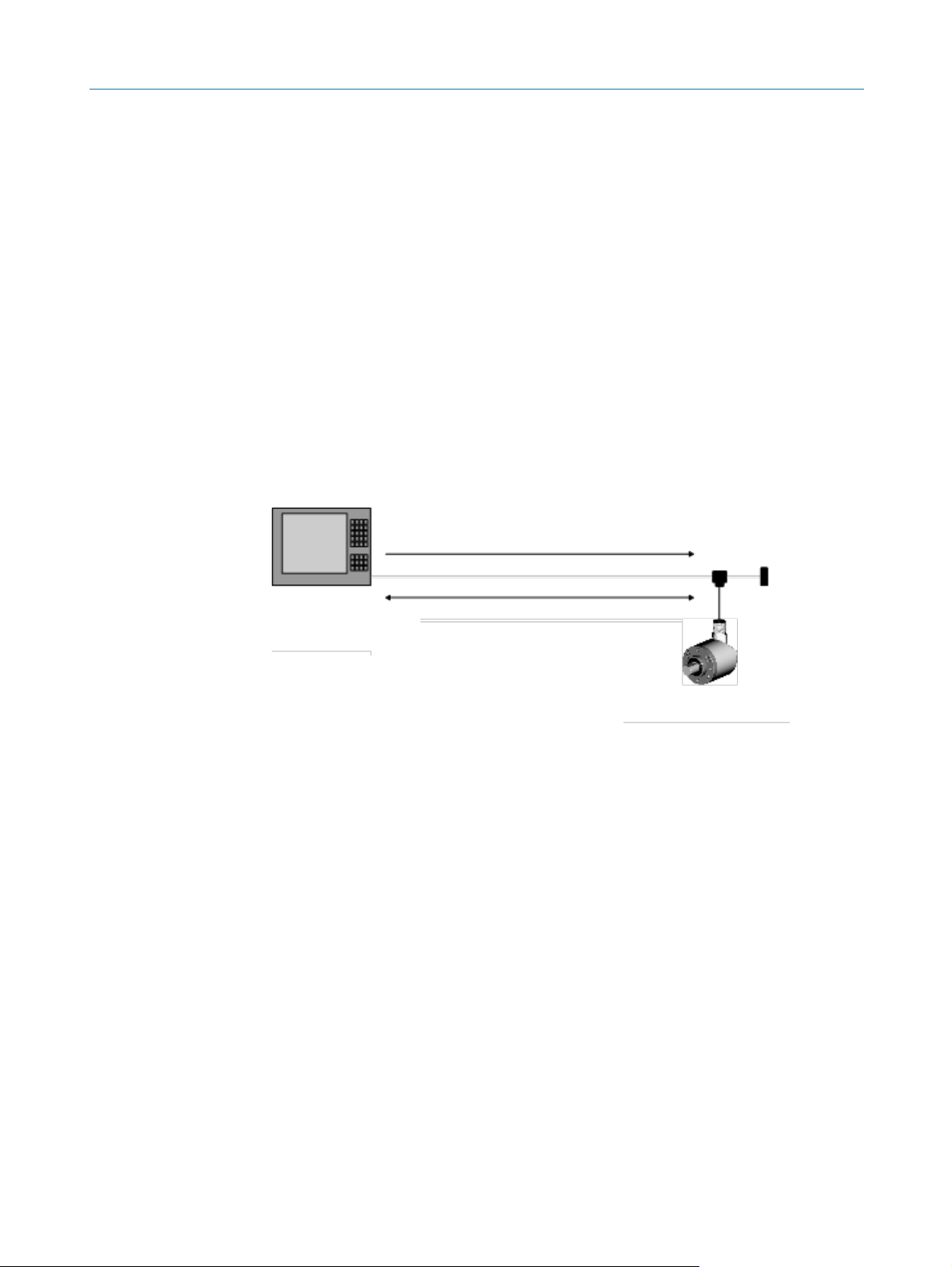
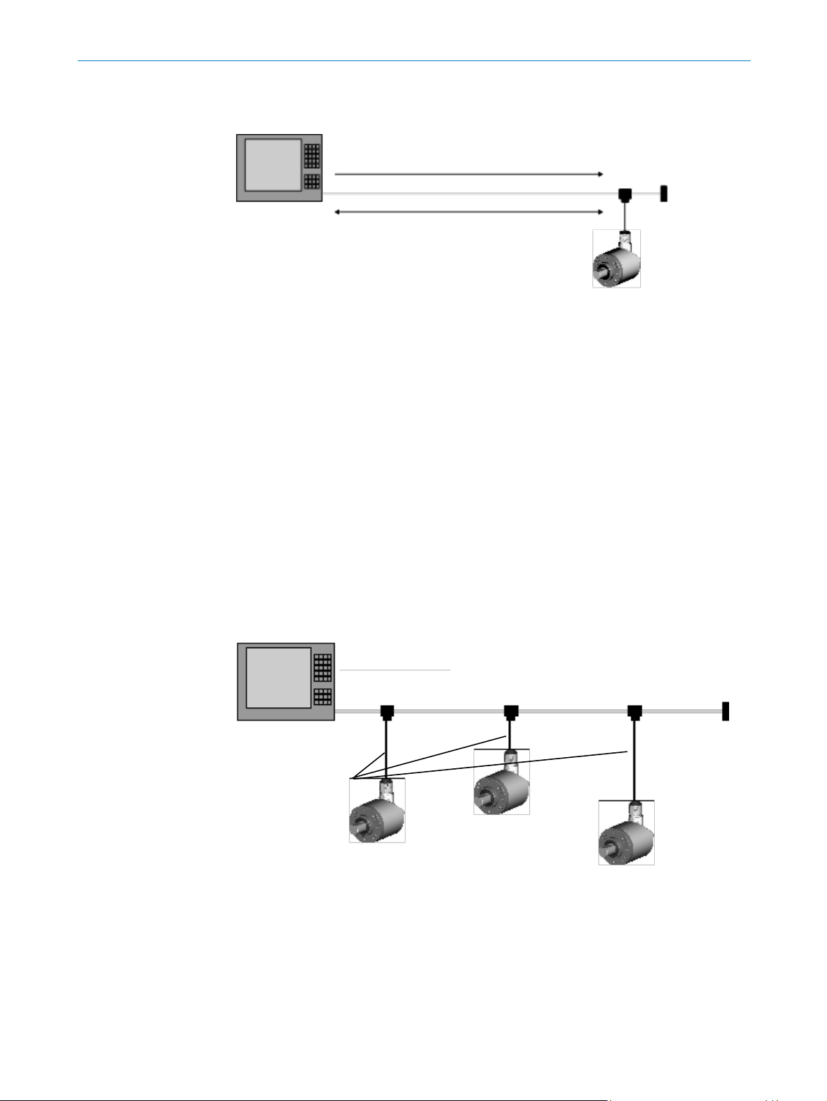
Figure 1: Encoder in the CANopen network
The following communication parameters can be assigned to the
AHS/AHM36 CANopen and AHS/AHM36 CANopen Inox:
Node ID: 1 to 127 (as a rule 0 is assigned to the master)
Baud rate: 10 kbit/s, 20 kbit/s, 50 kbit/s, 100 kbit/s, 125 kbit/s, 250 kbit/s,
500 kbit/s, 800 kbit/s, 1,000 kbit/s
Set the node ID and the baud rate as follows:
using the manufacturer-specific object 2009h
using Layer Setting Services (see section 5.4 on page 24)
Changing node ID and/or baud rate using the object 2009h
To change the node ID and/or the baud rate using the object 2009h, proceed as
follows:
Entering the access code in object 2009.1h: 98127634h
Change node ID and/or baud rate in the objects 2009.2h and 2009.3h
Save parameters with the aid of object 1010.1h: 65766173h (corresponds to
“save” in ASCII)
LSS, NMT
SDO, PDO, EMGY
Master
Node ID = 0
Slave
Node ID = 1 … 127
Page 12

3 QUICK START INSTRUCTIONS ON THE AHS/AHM36 CANOPEN AND AHS/AHM36 CANOPEN
INOX
12
OPERATING INSTRUC TIONS | AHS/AHM36 CANOP EN, AHS/AHM36 CANOPEN INOX 801 6869/1 2TG/2019-04-08 | SICK
Subject to change without notic e
NOTE
The changes will only be active after restarting the encoder (switch off and on again the
supply voltage).
Integration of several encoders
Integrate encoder 1 in the network and change the node ID (e.g. node ID 4).
Then integrate encoder 2 in the network and change the node ID if necessary.
NOTE
It is imperative you ensure there are not several encoders or other bus users with an
identical node ID in the same network.
3.2 Parameterization
3.2.1 EDS file
An EDS file is available for the straightforward interfacing of the AHS/AHM36 CANopen
and AHS/AHM36 CANopen Inox to a CANopen master. This file contains, amongst
others, the default parameters of the AHS/AHM36 CANopen and AHS/AHM36
CANopen Inox and the default configuration of the process data.
You can download the EDS file from www.sick.com:
Enter the seven-digit part number of your encoder directly in the Find field on the
homepage.
Click the related search result.
A page with all the information and files for your device will open.
Download the EDS file.
Integrate the EDS file in the engineering tool for your control.
3.2.2 Save or restore parameters
Saving modified parameters in the EEPROM – Save command
All parameters configured in the encoder’s EEPROM are saved using object 1010h.
For this purpose enter the command 65766173h (corresponds to “save” in ASCII)
in object 1010.1h.
NOTE
If the Save command is not run, the previous parameters will be loaded from the
EEPROM the next time the encoder is started.
Resetting encoders to default factory settings – Load command
The parameters are reset to the default factory settings using the object 1011h.
For this purpose enter the command 64616F6Ch (corresponds to “load” in ASCII)
in the object 1011.1h.
Page 13

QUICK START INSTRUCTIONS ON THE AHS/AHM36 CANOPEN AND AHS/AHM36 CANOPEN
INOX 3
8016869/12TG/201 9-04-08 | S ICK OPERATING INSTUCTIONS |AHS/AHM36 CA NOPEN, AHS/A HM36 CANOPEN INOX
13
Subject to change without notic e
NOTE
The node ID and baud rate set are not in general reset to the default factory settings.
The Save command must be run after the Load command. If the Save command is not
run, the previous parameters will be loaded from the EEPROM the next time the
encoder is started.
3.3 Process data objects (PDOs)
The AHS/AHM36 CANopen and AHS/AHM36 CANopen Inox supports four Transmit
PDOs and one Receive PDO.
Transmit PDOs
Data are sent by the encoder to the PLC using the four Transmit PDOs.
The four Transmit PDOs are defined by the following objects:
The objects 1800h … 1803h contain the communication parameters.
The objects 1A00h … 1A03h contain the mapping of the objects.
The mapping is variable and can be modified.
Receive PDO
Data are received from the PLC by the encoder using the Receive PDO. The mapping for
this Receive PDO is fixed and cannot be modified.
3.3.1 PDO communication
In the factory the transmission type for the Transmit PDOs is set to 255 in the objects
1800h … 1803h. This corresponds to the device-specific triggering.
NOTE
As an event timer is not configured, the Transmit PDOs are only transferred once on
changing to the Operational status!
Changing factory setting for transmission type
For the cyclic or acyclic output of the Transmit PDOs by the encoder, there are the
following options:
Change the event timer in the objects 1800h … 1803h (see Table 63 ff. from
page 56).
Configure a trigger event using the CoS event handling configuration (see
Table 119 on page 80).
Change the transmission type in the objects 1800h … 1803h (see Table 63 ff.
from page 56).
Pay attention to the inhibition time
The inhibition time for the PDOs (configured in the objects 1800.3h … 1803.3h) in
principle limits the communication of a device on the CANopen bus. It always has a
higher priority than the event timer, the CoS events and the sync triggering.
If, e.g., the event timer is set to 100 ms and the inhibition time is set to 1 s, the
corresponding PDO is only sent every second.
Page 14

3 QUICK START INSTRUCTIONS ON THE AHS/AHM36 CANOPEN AND AHS/AHM36 CANOPEN
INOX
14
OPERATING INSTRUC TIONS | AHS/AHM36 CANOP EN, AHS/AHM36 CANOPEN INOX 801 6869/1 2TG/2019-04-08 | SICK
Subject to change without notic e
3.3.2 PDO mapping
You will find which objects are mapped by default in the related transmit PDOs in
section 6.3.3 on page 56.
Page 15
PRODUCT DESCRIPTION 4
8016869/12TG/201 9-04-08 | S ICK OPERATING INSTUCTIONS |AHS/AHM36 CA NOPEN, AHS/A HM36 CANOPEN INOX
15
Subject to change without notic e
4 Product description
This chapter provides information on the special features and properties of the
Absolute Encoder AHS/AHM36 CANopen and AHS/AHM36 CANopen Inox. It describes
the construction and the operating principle of the device.
Please read this chapter before mounting, installing and commissioning the
device.
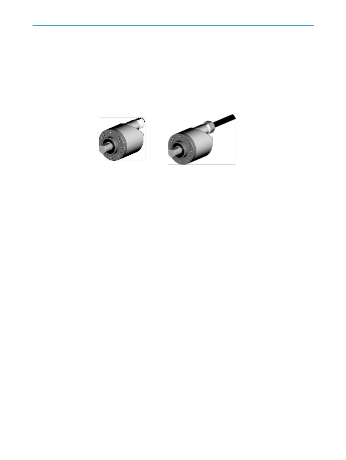
4.1 Special features
Figure 2: Connection types
With male connector
With cable outlet
Page 16

4 PRODUCT DESCRIPTION
16
OPERATING INSTRUC TIONS | AHS/AHM36 CANOP EN, AHS/AHM36 CANOPEN INOX 801 6869/1 2TG/2019-04-08 | SICK
Subject to change without notic e
Properties
Singleturn Encoder
Basic
Multiturn Encoder
Basic
Singleturn Encoder
Advanced
Multiturn Encoder
Advanced
Singleturn Encoder
Inox
Multiturn Encoder
Inox
CANopen interface
Supports the encoder profile CiA DS-406
Diagnostic functions via CANopen
–
–
12 bit singleturn resolution
(1 to 4,096 steps)
– – –
–
14 bit singleturn resolution
(1 to 16,384 steps)
–
–
12 bit multiturn resolution
(1 to 4,096 revolutions)
– – –
24 bit total resolution
– – – –
–
26 bit total resolution
– – – –
Round axis functionality
– – – –
Absolute Encoder in 36 mm design
Electro-sensitive, magnetic scanning
Flexible cable outlet/M12 male connector
Large number of mechanical adaptation options
Compact design
Face mount flange, servo flange, blind hollow
shaft
Stainless steel variant
– – –
–
Enclosure rating IP69K
– – –
–
Table 3: Special features of the encoder variants
Page 17

PRODUCT DESCRIPTION 4
8016869/12TG/201 9-04-08 | S ICK OPERATING INSTUCTIONS |AHS/AHM36 CA NOPEN, AHS/A HM36 CANOPEN INOX
17
Subject to change without notic e
4.2 Operating principle of the encoder
The sensing system in the AHS/AHM36 CANopen and AHS/AHM36 CANopen Inox
Absolute Encoder is based on absolute acquisition of revolutions without an external
voltage supply or battery. As a consequence the encoder can immediately output its
absolute position again after switching off and switching back on.
The AHS/AHM36 CANopen and AHS/AHM36 CANopen Inox acquires the position of
rotating axes and outputs the position in the form of a unique digital numeric value.
The highest reliability is achieved by means of electro-sensitive, magnetic scanning.
The AHS36 CANopen and AHS36 CANopen Inox is a singleturn encoder.
Singleturn encoders are used if absolute acquisition of the rotation of a shaft is
required.
The AHM36 CANopen and AHM36 CANopen Inox is a multiturn encoder.
Multiturn encoders are used if more than one shaft revolution must be acquired
absolutely.
4.2.1 Scaleable resolution
The resolution per revolution and the total resolution can be scaled and adapted to the
related application.
The resolution per revolution can be scaled in integers from 1 … 4,096 (Basic) or from
1 … 16,384 (Advanced / Inox).
The total resolution of the AHM36 CANopen and AHM36 CANopen Inox must be 2ⁿ
times the resolution per revolution. This restriction is not relevant if the round axis
functionality is activated.
4.2.2 Preset function
The position value for an encoder can be set with the aid of a preset value. I.e. the
encoder can be set to any position within the measuring range. In this way, e.g., the
encoder’s zero position can be adjusted to the machine’s zero point.
On switching off the encoder, the offset, the difference between the real position value
and the value defined by the preset, is saved. On switching back on the new preset
value is formed from the new real position value and the offset. Even if the position of
encoder changes while it is switched off, this procedure ensures the correct position
value is still output.
Figure 3: Saving the offset
= on switching off
= on switching back on
Offset
Encoder housing
Preset value
Difference
after switch-
ing back on
Offset
Encoder shaft
Page 18

4 PRODUCT DESCRIPTION
18
OPERATING INSTRUC TIONS | AHS/AHM36 CANOP EN, AHS/AHM36 CANOPEN INOX 801 6869/1 2TG/2019-04-08 | SICK
Subject to change without notic e
4.2.3 Round axis functionality
The encoder supports the function for round axes. The steps per revolution are set as a
fraction. As a result, the total resolution does not have to be configured to 2ⁿ times the
resolution per revolution and can also be a decimal number (e.g. 12.5).
NOTE
The output position value is adjusted with the zero point correction, the counting
direction set and the gearbox parameters entered.
Example with transmission ratio
A rotating table for a filling system is to be controlled. The resolution per revolution is
pre-defined by the number of filling stations. There are nine filling stations. For the
precise measurement of the distance between two filling stations, 1,000 steps are
required.
Figure 4: Example position measurement on a rotating table with transmission ratio
The number of revolutions is pre-defined by the transmission ratio = 12.5 of the
rotating table gearing.
The total resolution is then 9 × 1,000 = 9,000 steps, to be realized in 12.5 revolutions
of the encoder. This ratio cannot be realized via the resolution per revolution and the
total resolution, as the total resolution is not 2ⁿ times the resolution per revolution.
The application problem can be solved using the round axis functionality. Here the
resolution per revolution is ignored. The total resolution as well as the nominator and
divisor for the number of revolutions are configured.
9,000 steps are configured as the total resolution.
For the nominator for the number of revolutions 125 is configured, 10 as the divisor
(
125
/10 = 12.5).
After 12.5 revolutions (that is after one complete revolution of the rotating table) the
encoder reaches the total resolution of 9,000.
125
10
Rotating table with
nine filling
stations
Encoder
Page 19

PRODUCT DESCRIPTION 4
8016869/12TG/201 9-04-08 | S ICK OPERATING INSTUCTIONS |AHS/AHM36 CA NOPEN, AHS/A HM36 CANOPEN INOX
19
Subject to change without notic e
Example without transmission ratio
Figure 5: Example position measurement on a rotating table without transmission ratio
The encoder is mounted directly on the rotating table. The transmission ratio is 1:1.
The rotating table has 9 filling stations. The encoder must be configured such that it
starts to count with 0 at one filling station and counts to 999 on moving to the next
filling station position.
1,000 steps are configured as the total resolution.
For the nominator for the number of revolutions 1 is configured, 9 as the divisor (1/9
revolutions = 1,000).
After 1/9 revolutions of the encoder shaft there are 1,000 steps, then the encoder
starts to count at 0 again.
1,000 steps
Rotating table with nine filling stations
Encoder
Page 20
4 PRODUCT DESCRIPTION
20
OPERATING INSTRUC TIONS | AHS/AHM36 CANOP EN, AHS/AHM36 CANOPEN INOX 801 6869/1 2TG/2019-04-08 | SICK
Subject to change without notic e
4.2.4 Electronic cam mechanism
An electronic cam mechanism can be configured using the encoder. Two so-called CAM
channels with up to eight cam switching positions are supported . This is a limit
switch for the position.
Figure 6: Example electronic cam mechanism
Among other parameters, each cam has parameters for the lower switching point
and the upper switching point , which can be configured via CANopen (see section
6.4.2 on page 65).
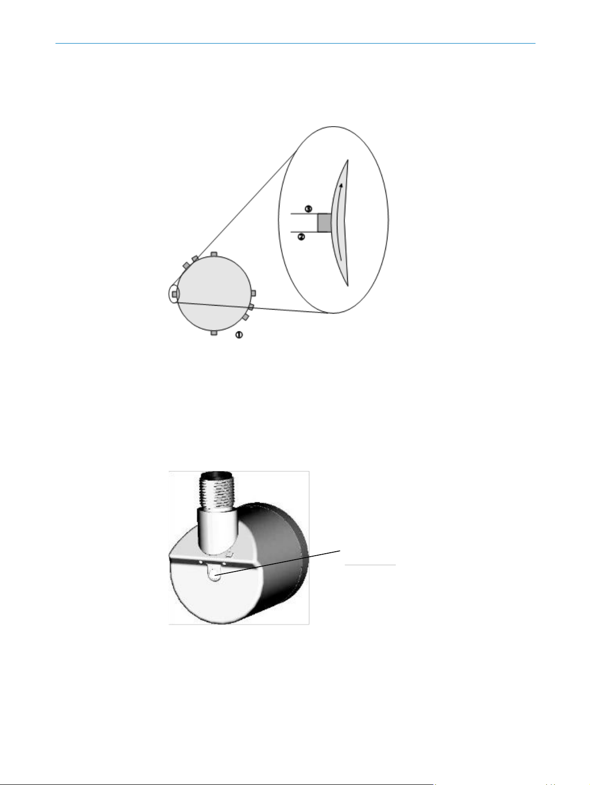
4.3 Controls and status indicators
The AHS/AHM36 CANopen and AHS/AHM36 CANopen Inox Absolute Encoder has one
status LED.
Figure 7: Position of the LED
The LED is multi-colored. Table 138 on page 97 shows the meaning of the signals.
LED
Page 21

INTEGRATION IN CANOPEN 5
8016869/12TG/201 9-04-08 | S ICK OPERATING INSTUCTIONS |AHS/AHM36 CA NOPEN, AHS/A HM36 CANOPEN INOX
21
Subject to change without notic e
5 Integration in CANopen
5.1 Communication profile
The CANopen communication protocol (documented in CiA DS-301) defines how the
devices exchange data with each other in a CANopen network.
5.1.1 CANopen in the OSI model
The CANopen protocol is a standardized layer-7 protocol for the CAN bus. This layer is
based on the CAN Application Layer (CAL).
The relevant objects in the encoder profile DS-406 are implemented in the
AHS/AHM36 CANopen and AHS/AHM36 CANopen Inox (see section 6.4 on page 61).
Figure 8: CANopen i n the OSI model
NOTE
Layers 3 … 6 are not used with CANopen.
5.1.2 Communication channels
CANopen has various communication channels (SDO, PDO, Emergency Messages).
These channels are formed with the aid of the Communication Object Identifier
CAN Application Layer (CAL), defined by DS-301
Bit transport layer
Data link layer
E.g. DS 401
E.g. DS 402
DS 406
Encoder
Page 22
5 INTEGRATION IN CANOPEN
22
OPERATING INSTRUC TIONS | AHS/AHM36 CANOP EN, AHS/AHM36 CANOPEN INOX 801 6869/1 2TG/2019-04-08 | SICK
Subject to change without notic e
(COB-ID). The COB-IDs are based on the node IDs for the individual devices on the
CANopen bus (see section 5.2 on page 23).
Figure 9: Communication channels
To set the encoder’s node ID, so-called Layer Setting Services (LSS) are used (see
section 5.4 on page 24).
Then communication with the encoder via the Network Management Services
(NMT) is possible (see section 5.5 on page 28) and its CANopen state machine
can be switched to the required status (Pre-operational, Operational or Stopped)
by the master.
In the Pre-operational status, Service Data Objects (SDO) can be used for commu-
nication and configuration (see section 5.6 on page 31). In the Operational status,
Process Data Objects (PDO) and Emergency Messages (EMGY) can also be used
for communication (see section 5.7 on page 33).
5.1.3 Topology
The AHS/AHM36 CANopen and AHS/AHM36 CANopen Inox is integrated in the
CANopen trunk using T-connectors (the T-connectors are available as accessories). The
trunk must be terminated at the end using a 120-Ohm terminator. In this way
reflections are prevented. This action is not necessary on the stubs to the encoders.
Figure 10: AHx36 in the CANopen topologie
Table 137 on page 90 shows the maximum length of the stubs for different baud rates.
LSS, NMT
SDO, PDO, EMGY
Master
Node ID = 0
Slave
Node ID = 1 … 127
Trunk
Stubs
Termination
PLC
Page 23

INTEGRATION IN CANOPEN 5
8016869/12TG/201 9-04-08 | S ICK OPERATING INSTUCTIONS |AHS/AHM36 CA NOPEN, AHS/A HM36 CANOPEN INOX
23
Subject to change without notic e
5.2 Node IDs and COB-IDs
The encoder’s node ID can be configured with the aid of the following methods:
SDO access to the manufacturer-specific object 2009h – Network Configuration
(see Table 122 on page 81)
access via Layer Setting Services (see section 5.4 on page 24)
There can be a maximum of 128 devices in a CANopen network, one master and up to
127 slaves. Each device is given a unique node ID (node address).
The COB-IDs (Communication Object Identifier) derive the communication channels
from this ID.
COB-ID calculation
[Dec]
[Hex]
ID ranges
[Dec]
[Hex]
Function
Direction as seen
from the encoder
0 0 Network management
Receive
128 + Node ID
0080h + Node ID
129 … 255
0081h … 00FFh
Emergency Message
Send
384 + Node ID
0180h + Node ID
385 … 511
0181h … 01FFh
Transmit PDO 1
Send
512 + Node ID
0200h + Node ID
513 … 639
0201h … 027Fh
Receive PDO 1
Receive
640 + Node ID
0280h + Node ID
641 … 767
0281h … 02FFh
Transmit PDO 2
Send
896 + Node ID
0380h + Node ID
897 … 1023
0381h … 03FFh
Transmit PDO 3
Send
1152 + Node ID
0480h + Node ID
1153 … 1279
0481h … 04FFh
Transmit PDO 4
Send
1408 + Node ID
0580h + Node ID
1409 … 1535
0581h … 05FFh
Transmit SDO
Send
1536 + Node ID
0600h + Node ID
1537 … 1663
0601h … 067Fh
Receive SDO
Receive
1792 + Node ID
0700h + Node ID
1793 … 1919
0701h … 077Fh
Node Guarding,
Heartbeat, Boot-Up
Send
2020
07E4h
2020
07E4h
Transmit LSS
Send
2021
07E5h
2021
07E5h
Receive LSS
Receive
Table 4: Communication object i dentifier for the encoder
Example:
The encoder is given the node ID = 5, it then sends emergency messages via the
ID 133, Transmit PDOs via the ID 389, 645, 901 as well as 1157 and the Transmit
SDO via the ID 1413.
Page 24

5 INTEGRATION IN CANOPEN
24
OPERATING INSTRUC TIONS | AHS/AHM36 CANOP EN, AHS/AHM36 CANOPEN INOX 801 6869/1 2TG/2019-04-08 | SICK
Subject to change without notic e
5.3 Baud rate
The transmission speed on the CANopen bus is defined using the baud rate. Pay
attention to the following criteria:
The same baud rate must be set on the AHS/AHM36 CANopen and AHS/AHM36
CANopen Inox as on the master.
The higher the baud rate in the CANopen network, the lower the bus load.
The longer the cables used, the lower the possible baud rate. Pay attention to the
maximum lenghts of the stubs depending on the baud rate (see Table 137 on
page 90).
The encoder supports the following baud rates:
Baud rate
Supported by the AHS/AHM36 CANopen and
AHS/AHM36 CANopen Inox
1,000 kbit/s
Yes
800 kbit/s
Yes
500 kbit/s
Yes
250 kbit/s
Yes
125 kbit/s
Yes
100 kbit/s
Yes
50 kbit/s
Yes
20 kbit/s
Yes
10 kbit/s
No
Automatic detection
No
Table 5: Supported baud rates
The encoder’s baud rate can be configured with the aid of the following methods:
SDO access to the manufacturer-specific object 2009h – Network Configuration
(see Table 122 on page 81)
access via Layer Setting Services (see section 5.4 on page 24)
5.4 Layer Setting Services (LSS)
To set the node ID and the baud rate of the AHS/AHM36 CANopen and AHS/AHM36
CANopen Inox, the Layer Setting Services are supported.
The LSS slave is accessed via its LSS address (identity object), which is saved in object
1018h (see Table 57 on page 53). The LSS address comprises:
manufacturer ID
product Code
revision number
serial number
Via the LSS the master requests the individual services that are then executed by the
AHS/AHM36 CANopen and AHS/AHM36 CANopen Inox. The communication between
the LSS master and LSS slave is undertaken using the LSS telegrams.
The following COB-IDs are used:
07E4h = LSS slave to LSS master
07E5h = LSS master to LSS slave
Page 25

INTEGRATION IN CANOPEN 5
8016869/12TG/201 9-04-08 | S ICK OPERATING INSTUCTIONS |AHS/AHM36 CA NOPEN, AHS/A HM36 CANOPEN INOX
25
Subject to change without notic e
Format of an LSS telegram
NOTE
An LSS telegram is always 8 bytes long. Byte 0 contains the Command Specifier (CS),
followed by 7 bytes for the data. All unused bytes must be set to zero.
COB-ID
Byte 0
Byte 1
Byte 2
Byte 3
Byte 4
Byte 5
Byte 6
Byte 7
CS
Data
Table 6: Format of an LSS telegram
Switch Mode Global
The Switch Mode Global command switches on or off the configuration mode. The
command is not acknowledged, the AHS/AHM36 CANopen and AHS/AHM36 CANopen
Inox does not respond.
COB-ID
Byte 0
Byte 1
Byte 2
Byte 3
Byte 4
Byte 5
Byte 6
Byte 7
07E5h
04h
Mode
00h
00h
00h
00h
00h
00h
Table 7: Format of the Switch Mode Global command
Byte 1 mode:
00h = switches off the LSS configuration mode
01h = switches to the LSS configuration mode
Configure Node ID
The node address is configured with the aid of this command.
COB-ID
Byte 0
Byte 1
Byte 2
Byte 3
Byte 4
Byte 5
Byte 6
Byte 7
07E5h
11h
Node ID
00h
00h
00h
00h
00h
00h
Table 8: Format of the Configure Node ID command
Byte 1 node ID:
01h = node address 1
…
7Fh = node address 127
Response:
COB-ID
Byte 0
Byte 1
Byte 2
Byte 3
Byte 4
Byte 5
Byte 6
Byte 7
07E4h
11h
Error
code
Error
extend
00h
00h
00h
00h
00h
Table 9: Response to the Configure Node ID command
Byte 1 error code:
00h = parameterization successful
01h = parameter invalid
FFh = contains a specific error code
Byte 2 error extend:
The error extension is manufacturer-specific and always 00h on the
AHS/AHM36 CANopen and AHS/AHM36 CANopen Inox.
Page 26

5 INTEGRATION IN CANOPEN
26
OPERATING INSTRUC TIONS | AHS/AHM36 CANOP EN, AHS/AHM36 CANOPEN INOX 801 6869/1 2TG/2019-04-08 | SICK
Subject to change without notic e
Configure Bit Timing Parameters
The baud rate is configured based on a baud rate table using this command.
COB-ID
Byte 0
Byte 1
Byte 2
Byte 3
Byte 4
Byte 5
Byte 6
Byte 7
07E5h
13h
00h
Table
index
00h
00h
00h
00h
00h
Table 10: Format of the Configure Bit Timing Parameters command
Byte 1 table index from the baud rate table:
Table index
Baud rate
Supported by the
AHS/AHM36 CANopen and
AHS/AHM36 CANopen Inox
0
1,000 kbit/s
Yes 1 800 kbit/s
Yes
2
500 kbit/s
Yes
3
250 kbit/s
Yes 4 125 kbit/s
Yes
5
100 kbit/s
Yes
6
50 kbit/s
Yes
7
20 kbit/s
Yes
8
10 kbit/s
No
9
Automatic detection
No
Table 11: Baud rate table
Response:
COB-ID
Byte 0
Byte 1
Byte 2
Byte 3
Byte 4
Byte 5
Byte 6
Byte 7
07E4h
13h
Error
code
Error
extend
00h
00h
00h
00h
00h
Table 12: Response to the Configure Bit Timing Parameters command
Byte 1 error code:
00h = parameterization successful
01h = parameter invalid
FFh = contains a specific error code
Byte 2 error extend:
The error extension is manufacturer-specific and always 00h on the
AHS/AHM36 CANopen and AHS/AHM36 CANopen Inox.
Store Configuration
This command saves the configuration.
NOTE
However, the configuration is not saved in non-volatile memory (EEPROM). This action
must be undertaken using the object 1010h – Save Parameters (see Table 50 on
page 51).
Page 27

INTEGRATION IN CANOPEN 5
8016869/12TG/201 9-04-08 | S ICK OPERATING INSTUCTIONS |AHS/AHM36 CA NOPEN, AHS/A HM36 CANOPEN INOX
27
Subject to change without notic e
COB-ID
Byte 0
Byte 1
Byte 2
Byte 3
Byte 4
Byte 5
Byte 6
Byte 7
07E5h
17h
00h
00h
00h
00h
00h
00h
00h
Table 13: Format of the Store Config uration command
Response:
COB-ID
Byte 0
Byte 1
Byte 2
Byte 3
Byte 4
Byte 5
Byte 6
Byte 7
07E4h
17h
Error
code
Error
extend
00h
00h
00h
00h
00h
Table 14: Response to the Store Configuration command
Byte 1 error code:
00h = save successful
01h = Store Configuration command is not supported
02h = memory error occurred
FFh = contains a specific error code
Byte 2 error extend:
The error extension is manufacturer-specific and always 00h on the
AHS/AHM36 CANopen and AHS/AHM36 CANopen Inox.
Inquire LSS address service
Using this command the encoder’s node ID and the manufacturer ID, the product code,
the revision number and the serial number can be read from object 1018h (see
Table 57 on page 53).
COB-ID
Byte 0
Byte 1
Byte 2
Byte 3
Byte 4
Byte 5
Byte 6
Byte 7
07E5h
CMD
00h
00h
00h
00h
00h
00h
00h
Table 15: Format of the Inqui re LSS address servi ce command
Byte 1 CMD from the command table:
CMD
Parameter
Subindex of object 1018h
5Eh
Node ID
5Dh
Serial Number
.4
5Ch
Revision Number
.3
5Bh
Product Code
.2
5Ah
Vendor ID
.1
Table 16: Command table
Response
COB-ID
Byte 0
Byte 1
Byte 2
Byte 3
Byte 4
Byte 5
Byte 6
Byte 7
07E4h
CMD
Data-X
{LsB}
Data-X
Data-X
Data-X
{MsB}
00h
00h
00h
Table 17: Response to the Inqui re LSS address service command
Page 28

5 INTEGRATION IN CANOPEN
28
OPERATING INSTRUC TIONS | AHS/AHM36 CANOP EN, AHS/AHM36 CANOPEN INOX 801 6869/1 2TG/2019-04-08 | SICK
Subject to change without notic e
NOTE
The data are 4 bytes long, in the byte order “Little Endian”. If the data read are shorter
than 4 bytes, the remaining bytes are filled with 0.
Identify Non-Configured Slave Device
Devices that have not been configured can be identified by with the aid of this
command.
COB-ID
Byte 0
Byte 1
Byte 2
Byte 3
Byte 4
Byte 5
Byte 6
Byte 7
07E5h
4Ch
00h
00h
00h
00h
00h
00h
00h
Table 18: Format of the Identify Non Configured Slave Device command
Response
COB-ID
Byte 0
Byte 1
Byte 2
Byte 3
Byte 4
Byte 5
Byte 6
Byte 7
07E4h
50h
00h
00h
00h
00h
00h
00h
00h
Table 19: Response to the Identify Non-Configured Slave Device command
5.5 Network management (NMT)
The Network Management (NMT) has the task of initializing users on a CANopen
network, adding the users to the network, stopping and monitoring them.
In a CANopen network there is always only one NMT master (Network Management
Master), all other devices, that is also the AHS/AHM36 CANopen and AHS/AHM36
CANopen Inox, are NMT slaves. The NMT master has control of all devices and can
change their status.
Typically an NMT master is realized by a PLC or a PC.
5.5.1 CANopen state machine
As in every CANopen slave, a so-called CANopen state machine is implemented in the
AHS/AHM36 CANopen and AHS/AHM36 CANopen Inox. A differentiation is made
between the following statuses:
Status
Description
Initializing
The initialization starts. The device application and the device
communication are initialized. Then the node switches automatically to
the Pre-operational status.
Pre-operational
The encoder is ready for configuration, acyclic communication can take
place via SDO. However, the encoder is not yet able to participate in
PDO communication and also does not send any emergency messages.
Operational
In this status the encoder is fully operational and can transmit
messages independently (PDOs, emergency messages).
Stopped
In this status the encoder is disabled for communication (active
connection monitoring via node guarding remains active).
Table 20: Status of the CANopen state machine
Page 29
INTEGRATION IN CANOPEN 5
8016869/12TG/201 9-04-08 | S ICK OPERATING INSTUCTIONS |AHS/AHM36 CA NOPEN, AHS/A HM36 CANOPEN INOX
29
Subject to change without notic e
5.5.2 Network Management Services
The specific status of the CANopen state machine is changed via the NMT services. The
NMT telegrams for device control use the COB-ID 0 and are given the highest priority.
COB-ID
Byte 0
Byte 1
Byte 2
Byte 3
Byte 4
Byte 5
Byte 6
Byte 7
00h
CCD
Node ID
00h
00h
00h
00h
00h
00h
Table 21: Format of the NMT telegram
Byte 0, CCD
Parameter
01h
Start Remote Node
Places the encoder in the Operational status.
02h
Stop Remote Node
Places the encoder in the Stopped status and stops its communication
(active connection monitoring via node guarding remains active).
80h
Enter Pre-operational
Places the encoder in the Pre-operational status. All communication
channels except the PDOs can be used.
81h
Reset node
Resets the value for the profile parameters to the default value. Then
the encoder changes to the Reset Communication status.
82h
Reset communication
Places the encoder in the Reset Communication status. Then the
encoder changes to the Initialization status.
Table 22: Meaning of byte 0
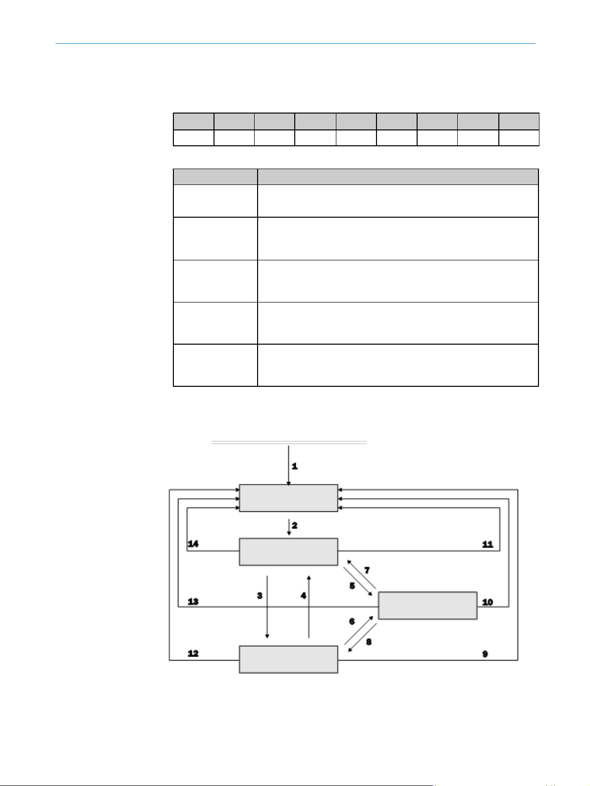
Transitions between the individual operating statuses
Figure 11: Transitions between the operating statuses
Initialization
Power-up or reset
Pre-operational
Operational
Stopped
Page 30

5 INTEGRATION IN CANOPEN
30
OPERATING INSTRUC TIONS | AHS/AHM36 CANOP EN, AHS/AHM36 CANOPEN INOX 801 6869/1 2TG/2019-04-08 | SICK
Subject to change without notic e
Transition
Description
1
After power-up the encoder enters the Initialization status.
2
After initialization the encoder automatically switches to the
Pre-operational status.
3 and 8
The encoder switches to the Operational status with the Start Remote
Node command.
4 and 7
The encoder switches back to the Pre-operational status with the Enter
Pre-operational State command.
5 and 6
The encoder switches to the Stopped status with the Stop Remote Node
command.
9, 10 and 11
The encoder switches to the Initialization status with the Reset Node
command.
12, 13 and 14
The encoder switches to the Initialization status with the Reset
Communication command.
Table 23: Transitions between the operating statuses
5.5.3 Boot-up message
To signal that a device is ready for operation after switching on, a so-called boot-up
message is sent. This message uses the ID from the NMT Error Control protocol and is
permanently linked to the device address set (700h + node ID).
5.5.4 Node Guarding and Heartbeat
The AHS/AHM36 CANopen and AHS/AHM36 CANopen Inox can be monitored
permanently using the Node Guarding protocol or the Heartbeat protocol.
NOTE
It is not possible to use the Node Guarding protocol and the Heartbeat protocol on one
node. If the Heartbeat Time parameter in the object 1017h is not equal to 0 (see
Table 56 on page 53), the Heartbeat protocol is used.
Node guarding
The status of the encoder is checked at regular intervals using the Node Guarding
telegram. The encoder responds within the response time configured in the objects
100Ch and 100Dh (see Table 48 on page 50).
COB-ID
Byte 0
Byte 1
Byte 2
Byte 3
Byte 4
Byte 5
Byte 6
Byte 7
700h +
Node ID
Status
00h
00h
00h
00h
00h
00h
00h
Table 24: Format of the Node Guarding telegram
Byte 0, status
Parameter
Bit 7
0
Bit 6 … 0
Operating status of the encoder:
127 = Pre-operational
5 = Operational
4 = Stopped
0 = boot up
Table 25: Meaning of byte 0
Page 31

INTEGRATION IN CANOPEN 5
8016869/12TG/201 9-04-08 | S ICK OPERATING INSTUCTIONS |AHS/AHM36 CA NOPEN, AHS/A HM36 CANOPEN INOX
31
Subject to change without notic e
Example for an encoder in the Operational status:
85h, 05h, 85h = no error
85h, 05h, 05h = error
NOTE
If node guarding is active, the encoder expects a corresponding status request from the
NMT master within a specific interval. If this is not the case, the slave changes to the
Pre-operational status.
Heartbeat
If the Heartbeat telegram is used, the encoder sends its status autonomously at regular
intervals. This status can be monitored by any other user in the network.
The heartbeat time is configured using object 1017h (see Table 56 on page 53).
COB-ID
Byte 0
Byte 1
Byte 2
Byte 3
Byte 4
Byte 5
Byte 6
Byte 7
700h +
Node ID
Status
00h
00h
00h
00h
00h
00h
00h
Table 26: Format of the Heartbeat tel egram
Byte 0, status
Parameter
Bit 7
Toggle bit
The bit changes its value after each request.
Bit 6 … 0
Operating status of the encoder:
127 = Pre-operational
5 = Operational
4 = Stopped
0 = Boot up
Table 27: Meaning of byte 0
5.6 Service Data Objects (SDO)
The Service Data Objects (SDO) form the communication channel for the transmission
of device parameters (e.g. programming the encoder resolution) and are used for
status requests.
Data of any length can be transmitted using SDOs. The data may need to be divided
between several CAN messages. An SDO is always transmitted with confirmation, i.e.
the reception of each message is acknowledged by the receiver.
Transmit SDO and Receive SDO
The AHS/AHM36 CANopen and AHS/AHM36 CANopen Inox has one Transmit SDO
channel and one Receive SDO channel to which two CAN identifiers are assigned.
The SDO communication is compliant with the client-server model. In this process the
encoder represents an SDO server.
The SDO client (e.g. the PLC) specifies in its request the parameter, the access type
(read/write) and, if necessary, the value. The encoder undertakes the write or read
access and responds to the request.
Page 32

5 INTEGRATION IN CANOPEN
32
OPERATING INSTRUC TIONS | AHS/AHM36 CANOP EN, AHS/AHM36 CANOPEN INOX 801 6869/1 2TG/2019-04-08 | SICK
Subject to change without notic e
The data area of a CAN telegram, maximum 8 bytes long, is configured by an SDO as
follows:
COB-ID
CCD
Index
Subindex
Data
600h +
Node ID
Byte 0
Byte 1
Byte 2
Byte 3
Byte 4
Byte 5
Byte 6
Byte 7
Table 28: Format of the SDO
The Command Code (CCD) identifies whether data are to be read or written. In the case
of an error, the data area contains a 4-byte error code that provides information on the
origin of the error (see section 8.4.3 on page 99).
Figure 12: Example for Transmit SDO and Receive SDO
In the example the encoder (ID = 5) receives from the PLC via the ID 0605h (Receive
SDO 0600h + encoder ID) a read request (CCD = 40h) for the object 1000h (see
Table 37 on page 48).
The encoder responds via ID 0585h (Transmit SDO 0580h + encoder ID) with the
return message (CCD = 43h) 0200h = multiturn encoder, 9601h device profile =
encoder.
Requirement
Response
Page 33

INTEGRATION IN CANOPEN 5
8016869/12TG/201 9-04-08 | S ICK OPERATING INSTUCTIONS |AHS/AHM36 CA NOPEN, AHS/A HM36 CANOPEN INOX
33
Subject to change without notic e
5.7 Process Data Objects (PDO)
Process data objects (PDO) are used for the quick and efficient exchange of real time
data (e.g. I/O data, set or actual values).
A PDO is transmitted without acknowledgment.
The AHS/AHM36 CANopen and AHS/AHM36 CANopen Inox supports one Receive PDO
and four Transmit PDOs.
Figure 13: Example for Transmit PDO and Receive PDO
8 data bytes are available on the transmission of the process data.
COB-ID
Data
0180h +
Node ID
Byte 0
Byte 1
Byte 2
Byte 3
Byte 4
Byte 5
Byte 6
Byte 7
Table 29: Format of the Transmit PDOs
5.7.1 PDO mapping
The format of the Transmit PDOs between the master and the encoder must be
harmonized by means of so-called PDO mapping. The process data can be arranged as
required in the PDO message. For this purpose the address (that is the index and
subindex) from the object directory as well as the size (number of bits) are entered in
the mapping object (see Table 68 ff. from page 58).
Example:
Object 1A00h contains the following objects by default:
6004.00h – Position Value
2010.01h – Device Status Word, S_STAT-A
2010.02h – Device Status Word, S_STAT-B
The contents of the objects are transmitted in the Transmit PDO.
COB-ID
Data
0180h +
Node ID
00
00
00
01
00
00
00
00
Position value = 1
No error
No error
Table 30: Example for a Transmit PDO
Receive PDO
Transmit PDO
Page 34

5 INTEGRATION IN CANOPEN
34
OPERATING INSTRUC TIONS | AHS/AHM36 CANOP EN, AHS/AHM36 CANOPEN INOX 801 6869/1 2TG/2019-04-08 | SICK
Subject to change without notic e
5.7.2 PDO data transmission
Bus load
Please note:
The more PDOs and the more often these PDOs are sent, the higher the bus load
in the CANopen network.
The higher the baud rate in the CANopen network, the lower the bus load.
The longer the cables used, the lower the possible baud rate.
For optimal communication a compromise therefore needs to be found between all
three factors mentioned.
If a Transmit PDO is not used, it should be deactivated. For this purpose set bit 31 to 1
in subindex .1 of the related object 180xh.
The PDOs can be transmitted cyclically or acyclically. This aspect is defined by the
objects 180xh and the transmission type defined in their subindex .02.
Object
Subindex
Designation
Data values
180xh
Communication
Parameter for the
1st Transmit PDO
–
.0
Number of entries
5
.1
COB-ID
00000180h + Node ID
.2
Transmission Type
0 Transmission only on switching on the encoder
1 … 240 Cyclic transmission. Cyclic with the SYNC
messages
252 Request by RTR telegram (synchronous
transmission)
253 Request by RTR telegram (asynchronous
transmission)
254 Application-specific triggering
255 Device-specific triggering
.3
Inhibition Time
0 … 65,535
.4
Reserved
–
.5
Event Timer
0 … 65,535
Table 31: Example for the communication parameters
Page 35

INTEGRATION IN CANOPEN 5
8016869/12TG/201 9-04-08 | S ICK OPERATING INSTUCTIONS |AHS/AHM36 CA NOPEN, AHS/A HM36 CANOPEN INOX
35
Subject to change without notic e
Cyclic data transmission
For cyclic data transmission there are the following options:
The process data are sent with the master’s SYNC messages. The cycle is formed
from a multiple of the Sync messages. The factor can be between 1 and 240.
The process data are sent using an event timer to suit the specific application or
device. An event timer is available for each PDO. It can be configured between 0
and 65,535 ms.
Acyclic data transmission
For acyclic data transmission the encoder is triggered by one of the following criteria:
On application-specific/device-specific triggering
The transmission of the PDOs is controlled by an event (CoS triggering). This event
is defined in object 2007h (see Table 119 on page 80).
On request (RTR telegram)
In this case another bus user (as a rule the master) requests the process data.
NOTE
The combination of cyclic and acyclic data transmission by event timer and CoS
triggering is not permitted.
Event timer and CoS triggering do not limit each other!
If an object is to be transmitted cyclically and acyclically, it must be mapped to two
different PDOs.
NOTE
In the factory the encoder’s Transmit PDOs are set to device-specific triggering. As a
consequence the encoder outputs all Transmit PDOs once on start-up. However the
event timer is at 0. For this reason the Transmit PDOs are initially only output once.
For the cyclic or acyclic output of the Transmit PDOs by the encoder, there are the
following options:
Change the event timer in the objects 1800h … 1803h (see Table 63 ff. from
page 56).
Configure a trigger event using the CoS event handling configuration (see
Table 119 on page 80).
Change the transmission type in the objects 1800h … 1803h (see Table 63 ff.
from page 56).
Inhibition time
The inhibition time for the PDOs (configured in the objects 1800.3h … 1803.3h) in
principle limits the communication of a device on the CANopen bus. It always has a
higher priority than the event timer, the CoS events and the sync triggering.
If, e.g., the event timer is set to 100 ms and the inhibition time is set to 1 s, the
corresponding PDO is only sent every second.
NOTE
The inhibition time has no effect on triggering by RTR telegrams.
Page 36

5 INTEGRATION IN CANOPEN
36
OPERATING INSTRUC TIONS | AHS/AHM36 CANOP EN, AHS/AHM36 CANOPEN INOX 801 6869/1 2TG/2019-04-08 | SICK
Subject to change without notic e
Figure 14: Sending Transmit PDOs
5.7.3 Asynchronous or synchronous formation of the position
With bit 15 of object 6000h (see Table 74 on page 62) you can define whether the
position is formed asynchronously or synchronously.
Asynchronous formation of the position
The formation of the position by the encoder is not synchronized. It operates
autonomously using its own cycle. The encoder determines the position every
250 µs
1
)
with a jitter of 20 µs. A PDO always “takes” the last position value, which
may already be 250 µs old.
Synchronous formation of the position
The formation of the position by the encoder is synchronized to the Sync messages from the master. The AHS/AHM36 CANopen and AHS/AHM36 CANopen Inox
forms the position on the reception of a SYNC message. In this case it is not
possible to determine a speed value, the speed is output as 0.
NOTE
The output data from the master (essentially for the preset function) cannot be
synchronized.
The input data for the master (essentially the position data) can be synchronized.
1
)
Additional latency time due to sensor-internal processes: 500 µs.
From the master
Inhibition
time
reached?
RTR telegram
One PDO (e.g. Transmit PDO 1) to the master
SYNC telegram
Event timer
CoS triggering
Device-specific
Application specific
Yes
No
Page 37

INTEGRATION IN CANOPEN 5
8016869/12TG/201 9-04-08 | S ICK OPERATING INSTUCTIONS |AHS/AHM36 CA NOPEN, AHS/A HM36 CANOPEN INOX
37
Subject to change without notic e
5.8 Configurable functions
The AHS/AHM36 CANopen and AHS/AHM36 CANopen Inox is configured, e.g., in the
TwinCAT® configuration tool with the aid of various objects.
The most important objects for the configuration of the functions are listed in the
following. A complete list of the objects can be found in chapter 6 “Object library” on
page 46.
WARNING
During the configuration of the encoder, make sure there are no persons in a
system’s hazardous area!
All parameter changes have a direct effect on the operation of the encoder. For this
reason the position value may change during configuration, e.g. due to the
implementation of a preset or change of scale. This change could cause an unexpected
movement that may result in a hazard for persons or damage to the system or other
items.
NOTE
All functions described in the following for which parameters can be set can also be
configured in the encoder’s start-up configuration.
5.8.1 EDS file
To be able to integrate the AHS/AHM36 CANopen and AHS/AHM36 CANopen Inox
straightforwardly in a CANopen master, there is an EDS file. This file contains the
following information on the features of the AHS/AHM36 CANopen and AHS/AHM36
CANopen Inox:
information on the manufacturer of the device
name, type and version number of the device
type and version number of the protocol used for this device
default parameters of the AHS/AHM36 CANopen and AHS/AHM36 CANopen Inox
and default configuration of the process data
Figure 15: EDS file
PLC
EEPROM
AHS/AHM36 CANopen and
AHS/AHM36 CANopen Inox
Page 38

5 INTEGRATION IN CANOPEN
38
OPERATING INSTRUC TIONS | AHS/AHM36 CANOP EN, AHS/AHM36 CANOPEN INOX 801 6869/1 2TG/2019-04-08 | SICK
Subject to change without notic e
5.8.2 Scaling parameters
The scaling parameters are configured by the objects 6000h, 6001h and 6002h.
Figure 16: Objects 6000h, 6001h and 6002h in TwinCAT®
6000h – Operating Parameters
Using the object 6000h (see Table 74 on page 62) the parameters Support additional
Error Code, Scaling and Code sequence are configured. The object is configured using
a bit sequence 16 bits wide.
Example:
Bit 0 = code sequence ccw = 1
Bit 2 = scaling on = 1
Bit
15
14
13
12
11
10 9 8 7 6 5 4 3 2 1 0
Value 0 0 0 0 0 0 0 0 0 0 0 0 0 1 0 1
Table 32: Example for binary code
The binary value must be converted into a hexadecimal value and entered in the
configuration dialog box.
101b = 5h
Figure 17: Example for the parameterization of object 6000h
Scaling
This parameter makes it possible to scale the resolution per revolution and the total
resolution.
NOTE
Only if the parameter Scaling is configured to 1 are the values entered for the
resolution and total resolution applied.
Code sequence
The code sequence defines which direction of rotation increases the position value; the
direction of rotation is defined looking at the shaft.
clockwise (cw) = increasing position value on clockwise revolution of the shaft
counterclockwise (ccw) = increasing position value on counter clockwise
revolution of the shaft
Page 39

INTEGRATION IN CANOPEN 5
8016869/12TG/201 9-04-08 | S ICK OPERATING INSTUCTIONS |AHS/AHM36 CA NOPEN, AHS/A HM36 CANOPEN INOX
39
Subject to change without notic e
6001h – Counts Per Revolution (CPR)
The resolution per revolution is configured using the object 6001h (see Table 76 on
page 63).
NOTE
The parameter is not used if the round axis functionality is activated.
Figure 18: Example for the parameterization of object 6001h
The resolution of the AHS/AHM36 CANopen Basic is max. 4,096 steps per revolution.
The resolution can be scaled from 1 … 4,096 as an integer.
The resolution of the AHS/AHM36 CANopen Advanced / Inox is max. 16,384 steps per
revolution. The resolution can be scaled from 1 … 16,384 as an integer.
6002h – Total Measuring Range
The total resolution is configured using the object 6002h (see Table 77 on page 63).
Figure 19: Example for the parameterization of object 6002h
The total resolution, that is the measuring range of the AHM36 CANopen Basic, is max.
16,777,216 steps. The total resolution of the AHM36 CANopen Advanced / Inox is
max. 67,108,864 steps.
The total resolution must be 2ⁿ times the resolution per revolution.
NOTE
This restriction is not relevant if the round axis functionality is activated.
Resolution per revolution
n
Total resolution
1,000
3
8,000
8,179
5
261,728
2,048
11
4,194,304
Table 33: Examples for total resolution
Page 40

5 INTEGRATION IN CANOPEN
40
OPERATING INSTRUC TIONS | AHS/AHM36 CANOP EN, AHS/AHM36 CANOPEN INOX 801 6869/1 2TG/2019-04-08 | SICK
Subject to change without notic e
NOTE
The parameters are only written to the non-volatile memory in the EEPROM using the
object 1010h with the aid of the data word 65766173h = “save” (see Table 50 on
page 51).
5.8.3 Preset function
The position value for an encoder can be set with the aid of the preset function. I.e. the
encoder can be set to any position within the measuring range.
NOTE
The preset value must lie within the measuring range configured.
WARNING
Before triggering the preset function, check whether there is a hazard from the
machine or system in which the encoder is integrated!
The preset function results in a change in the position value output by the encoder.
This change could cause an unexpected movement that may result in a hazard for
persons or damage to the system or other items.
The preset value can be set with the aid of the following methods:
using acyclic communication (SDO) with the object 6003h
using cyclic communication (PDO) with the object 2000h. The value from object
2005h is used.
Acyclic communication (SDO)
The preset value is transferred directly to the encoder using the object 6003h – Preset
Value (see Table 78 on page 63). The encoder immediately adopts the preset value
that is written to the object as the new position value.
Figure 20: Example for the parameterization of object 6003h
The function is available if the encoder is in the Pre-operational or Operational status.
Page 41

INTEGRATION IN CANOPEN 5
8016869/12TG/201 9-04-08 | S ICK OPERATING INSTUCTIONS |AHS/AHM36 CA NOPEN, AHS/A HM36 CANOPEN INOX
41
Subject to change without notic e
Cyclic communication (PDO)
The preset value is initially transferred to the encoder using the object 2005h –
Configuration Preset Value (see Table 117 on page 78), but is not yet applied as a
new position value.
Figure 21: Example for the parameterization of object 2005h
The function is triggered using the object 2000h – Control Word 1 (see Table 111 on
page 75).
The function is available if the encoder is in the Operational status.
The object is configured using a bit sequence 16 bits wide.
Example:
Bit 12 = preset is set = 1
Bit 11 = preset mode shift positive = 1
Bit
15
14
13
12
11
10 9 8 7 6 5 4 3 2 1 0
Value 0 0 0 1 1 0 0 0 0 0 0 0 0 0 0 0
Table 34: Example for binary code
The binary value must be converted into a hexadecimal value and entered in the
configuration dialog box.
1100000000000b = 1800h
5.8.4 Cyclic process data
The cyclic process data are defined using the process data objects (see section 6.3 on
page 54).
The object to be incorporated in the objects 1A00h, 1A01h, 1A02h or 1A03h is
entered with its object number, the subindex and the data length (see Table 72 on
page 60).
Figure 22: Example for the parameterization of object 1A00h
Page 42

5 INTEGRATION IN CANOPEN
42
OPERATING INSTRUC TIONS | AHS/AHM36 CANOP EN, AHS/AHM36 CANOPEN INOX 801 6869/1 2TG/2019-04-08 | SICK
Subject to change without notic e
Example:
Figure 23: Example for the parameterization of subindex 1A00.01h
60040020h
Object = 6004h
Subindex = 00h
Data length = 20h (32 Bit)
NOTE
In the factory the encoder’s Transmit PDOs are set to device-specific triggering. As a
consequence the encoder outputs all Transmit PDOs once on start-up. However the
event timer is at 0. For this reason the Transmit PDOs are initially only output once.
For the cyclic or acyclic output of the Transmit PDOs by the encoder, there are the
following options:
Change the event timer in the objects 1800h … 1803h (see Table 63 ff. from
page 56).
Configure a trigger event using the CoS event handling configuration (see
Table 119 on page 80).
Change the transmission type in the objects 1800h … 1803h (see Table 63 ff.
from page 56).
5.8.5 Speed measurement
The speed measurement is configured using the object 2002h – Speed Calculation
Configuration (see Table 114 on page 77).
Figure 24: Example for the parameterization of object 2002h
Page 43

INTEGRATION IN CANOPEN 5
8016869/12TG/201 9-04-08 | S ICK OPERATING INSTUCTIONS |AHS/AHM36 CA NOPEN, AHS/A HM36 CANOPEN INOX
43
Subject to change without notic e
Using the subindex 2002.02h – Format: Measuring Units you can define the units in
which the speed is transmitted.
Figure 25: Example for the parameterization of subindex 2002.02h
Possible units are:
cps
cp10ms
cp100ms
rpm
rps
The factory setting is 3h = rpm.
Using the other Subindices you can configure the refresh time as well as the maximum
and minimum speed (see Table 114 on page 77).
5.8.6 Round axis functionality
The Round axis functionality removes the restriction for the AHM36 Advanced / Inox
that the total resolution must be 2ⁿ times the resolution per revolution. The shaft is
considered as an endless shaft.
The resolution per revolution is not configured directly, instead the nominator and
divisor for the number of revolutions are defined.
The Round axis functionality is configured using the object 2001h – Endless-Shaft
Configuration (see Table 113 on page 76).
Figure 26: Example for the parameterization of object 2001h
Page 44

5 INTEGRATION IN CANOPEN
44
OPERATING INSTRUC TIONS | AHS/AHM36 CANOP EN, AHS/AHM36 CANOPEN INOX 801 6869/1 2TG/2019-04-08 | SICK
Subject to change without notic e
The total resolution can be scaled from 1 … 67,108,864 (Advanced / Inox) as an
integer.
The nominator (2001.02h – Number of Revolutions, Nominator) can be scaled from
1 … 2,048 as an integer. The default factory setting for the nominator is 2,048.
Figure 27: Example for the parameterization of subindex 2001.03h
The divisor (2001.03h – Number of Revolutions, Divisor) can be scaled from 1 … 2,048
as an integer. The default factory setting for the divisor is 1.
Due to the physical limit of the resolution per revolution, the following condition also
applies:
Total resolution ÷ (nominator for the number of revolutions ÷ divisor for the number of
revolutions) ≤ 16,384.
Page 45

INTEGRATION IN CANOPEN 5
8016869/12TG/201 9-04-08 | S ICK OPERATING INSTUCTIONS |AHS/AHM36 CA NOPEN, AHS/A HM36 CANOPEN INOX
45
Subject to change without notic e
5.8.7 Electronic cam mechanism
An electronic cam mechanism can be configured using the encoder. Two so-called CAM
channels with up to eight cam switching positions are supported. This is a limit switch
for the position.
The electronic cam mechanism is configured using several objects (see section 6.4.2
“Objects for the electronic cam mechanism (CAM)” on page 65).
Figure 28: Objects for the electronic cam mechanism
The cams are enabled using the object 6301h – CAM Enable Register, the polarity is
defined using the object 6302h – CAM Polarity Register.
Each position parameter is defined by its minimum switching point (objects 6310h to
6317h), its maximum switching point (objects 6320h to 6327h) and its switching
hysteresis (objects 6330h to 6337h).
Page 46

6 OBJECT LIBRARY
46
OPERATING INSTRUC TIONS | AHS/AHM36 CANOP EN, AHS/AHM36 CANOPEN INOX 801 6869/1 2TG/2019-04-08 | SICK
Subject to change without notic e
6 Object library
The AHS/AHM36 CANopen and AHS/AHM36 CANopen Inox contains various types of
objects:
standard objects with 1000 series object numbers
encoder profile-specific objects with 6000 series object numbers
manufacturer-specific objects with 2000 series object numbers
6.1 Nomenclature
Abbreviation
Meaning
R
Read = read only
R/W
Read/Write = read and write access
STRG
String = character string of variable length
BOOL
Boolean = logical value 0 or 1
INT
Integer value (negative/positive)
(e.g. INT-8 = –128 … +127)
UINT
Unsigned integer = integer value
(e.g. UINT-32 = 0 … 4.294.967.295)
Array
Series of data of one data type
(e.g. array UINT-8 = character string of data type UINT-8)
Record
Series of data with different data types
(e.g. UINT-8, UINT-32, UINT-32, UINT-16)
Table 35: Nomenclature of the access types and data types
Page 47

OBJECT LIBRARY 6
8016869/12TG/201 9-04-08 | S ICK OPERATING INSTUCTIONS |AHS/AHM36 CA NOPEN, AHS/A HM36 CANOPEN INOX
47
Subject to change without notic e
6.2 Standard objects
Object
Subindex
Access
Data type
Designation
1000h
R
UINT-32
Device Type
1001h
R
UINT-8
Error Register
1003h
R/W
Record
Predefined Error Field
1005h
R/W
UINT-32
COB-ID SYNC Message
1008h
R
STRG
Device Name
1009h
R
STRG
Hardware Version Number
100Ah
R
STRG
Software Version Number
100Ch
R/W
UINT-16
Node Guarding – Guard Time
100Dh
R/W
UINT-8
Node Guarding – Life Time Factor
1010h
.0 … .1
R/W
Record
Save Parameters
1011h
.0 … .1
R/W
Record
Load/Restore Parameters
1014h
R/W
UINT-32
COB-ID Emergency Message
1015h
R/W
UINT-16
Emergency Inhibit Time
1017h
R/W
UINT-16
Heartbeat Time
1018h
.0 … .4
R
Record
Identity Object
1400h
.0 … .2
R/W
Record
Communication Parameter for the
1st Receive PDO
1600h
.0 and .1
R/W
Record
Mapping Parameter for the
1st Receive PDO
1800h
.0 … .5
R/W
Record
Communication Parameter for the
1st Transmit PDO
1801h
.0 … .5
R/W
Record
Communication Parameter for the
2nd Transmit PDO
1802h
.0 … .5
R/W
Record
Communication Parameter for the
3rd Transmit PDO
1803h
.0 … .5
R/W
Record
Communication Parameter for the
4th Transmit PDO
1A00h
.0 … .3
R/W
Record
Mapping Parameter for the
1st Transmit PDO
1A01h
.0 … .4
R/W
Record
Mapping Parameter for the
2nd Transmit PDO
1A02h
.0 … .3
R/W
Record
Mapping Parameter for the
3rd Transmit PDO
1A03h
.0 … .4
R/W
Record
Mapping Parameter for the
4th Transmit PDO
Table 36: Impl emented standard objects
Page 48

6 OBJECT LIBRARY
48
OPERATING INSTRUC TIONS | AHS/AHM36 CANOP EN, AHS/AHM36 CANOPEN INOX 801 6869/1 2TG/2019-04-08 | SICK
Subject to change without notic e
6.2.1 Detailed information on the standard objects
NOTE
In the following only those objects are described in detail for which the content is not
clear from the overview (see Table 36 on page 47).
Object 1000h – Device Type
This object specifies the device type and the device profile implemented.
Object
Access
Data type
Designation
Data values
1000h
R
UINT-32
Device Type
See Table 38
Table 37: Object 1000h
Bit
Description
Data values
31 … 24
The device type is output in the bits 31 … 16.
01h Singleturn encoder
02h Multiturn encoder
23 … 16
15 … 8
The device profile supported is output in the bit
15 … 0.
01.96h Device profile =
Encoder
7 … 0
Table 38: Object 1000h – details
Object 1001h – Error Register
Object
Access
Data type
Designation
Data values
1001h
R
UINT-8
Error Register
See Table 40
Table 39: Object 1001h
The encoder writes error messages to this object. It is part of the emergency message
(see section 8.4.1 on page 97).
Bit
Description
Data values
7
Manufacturer-specific error
0 Not active
1 Active
6
Reserved
0
5
Device profile specific error
0 Not active
1 Active
4
Communication error (PDO length exceeded)
0 Not active
1 Active
3
Temperature error
0 Not active
1 Active
2
Voltage error
0 Not active
1 Active
1
Reserved
0
0
Generic error
0 Not active
1 Active
Table 40: Object 1001h – details
Page 49

OBJECT LIBRARY 6
8016869/12TG/201 9-04-08 | S ICK OPERATING INSTUCTIONS |AHS/AHM36 CA NOPEN, AHS/A HM36 CANOPEN INOX
49
Subject to change without notic e
Object 1003h – Predefined Error Field
Object
Subindex
Access
Data type
Designation
Data values
1003h
R/W
Record
Predefined Error Field
–
.0
R/W
UINT-8
Number of entries
0 … 4
.1 R UINT-32
Error 1
00000000h … FFFFFFFFh
.2 R UINT-32
Error 2
00000000h … FFFFFFFFh
.3 R UINT-32
Error 3
00000000h … FFFFFFFFh
.4 R UINT-32
Error 4
00000000h … FFFFFFFFh
Table 41: Object 1003h
NOTE
The number of errors is saved in the subindex .0. If an error has not yet occurred,
the value of the subindex is = 0. Read access is responded to with an SDO error
message 08000024h or 08000000h.
Each new error is saved in subindex .1, older errors move to the next higher
subindex.
To delete the error list, 00h must be written to subindex .0.
Byte 0
1 2 3
Object 1003h
S_STAT-A-LsB
S_STAT-A-MsB
EMGY error code
Error field
Table 42: Object 1003h – details
Object 1005h – COB-ID SYNC Message
Object
Access
Data type
Designation
Data values
1005h
R/W
UINT-32
COB-ID SYNC Message
See Table 44
Table 43: Object 1005h
Bit
Description
Data values
31
Reserved
0
30
Defines whether the device generates the SYNC
message.
0 Device does not
generate a SYNC
message.
1 Not supported
29
Defines which bit width is used.
0 11 Bit
1 Not supported
28 … 0
29-bit width CAN ID
0
11 … 0
11-bit width CAN ID
80h
Table 44: Object 1005h – details
Page 50

6 OBJECT LIBRARY
50
OPERATING INSTRUC TIONS | AHS/AHM36 CANOP EN, AHS/AHM36 CANOPEN INOX 801 6869/1 2TG/2019-04-08 | SICK
Subject to change without notic e
Object 1008h – Device Name
The object contains the device name dependent on the encoder type.
Object
Access
Data type
Designation
Data values
1008h
R
STRG
16 byte
Device Name
AHS36B-xxCx04096
AHM36B-xxCx12x12
AHS36A-xxCx16384
AHM36A-xxCx14x12
Table 45: Object 1008h
Object 1009h – Hardware Version Number
Object
Access
Data type
Designation
Data values
1009h
R
STRG
8 byte
Hardware Version Number
E.g. HW_01.01
(depending on the release)
Table 46: Object 1009h
Object 100Ah – Software Version Number
Object
Access
Data type
Designation
Data values
100Ah
R
STRG
8 byte
Software Version Number
E.g. SW_01.01
(depending on the release)
Table 47: Object 100Ah
Object 100Ch – Node Guarding – Guard Time
Object
Access
Data type
Designation
Description
Data values
100Ch
R/W
UINT-16
Node Guarding – Guard
Time
Configured monitoring time
in ms
0000h … 7FFFh
Table 48: Object 100Ch
Object 100Dh – Node Guarding – Life Time Factor
Object
Access
Data type
Designation
Description
Data values
100Dh
R/W
UINT-8
Node Guarding – Life Time
Factor
Factor for the multiplication
of the monitoring time
64h … FFh
Table 49: Object 100Dh
The monitoring time multiplied by the life time factor yields the cycle used to monitor
the encoder.
Page 51

OBJECT LIBRARY 6
8016869/12TG/201 9-04-08 | S ICK OPERATING INSTUCTIONS |AHS/AHM36 CA NOPEN, AHS/A HM36 CANOPEN INOX
51
Subject to change without notic e
Object 1010h – Save Parameters
Using this object the parameters are written to EEPROM with the aid of the data word
65766173h = “save” (ASCII code).
WARNING
Check whether the parameters have actually been written to the EEPROM!
The data are only written to the EEPROM in the status Pre-operational. The command is
not executed in any other status, but it is also not identified as denied.
Check whether the parameters have been saved using the object 2010.03h –
State Flag 3 (S_STAT-C) (see Table 126 on page 83).
If the data are not saved in the EEPROM, the encoder loads the data last saved the
next time the encoder is switched on. This situation can result in hazards for persons or
damage to the system!
Object
Subindex
Access
Data type
Designation
Description
Data values
1010h
R/W
Record
Save Parameters
–
.0
R/W
UINT-8
Number of entries
1
.1
R/W
UINT-32
Total Class Parameters
The parameters for all
object types are saved.
See Table 51
Table 50: Object 1010h
Bit
Designation
Data values
31 … 24
Byte 3
65h = e
23 … 16
Byte 2
76h = v
15 … 8
Byte 1
61h = a
7 … 0
Byte 0
73h = s
Table 51: Object 1010h – details
Object 1011h – Load/Restore Parameter
Using this object the parameters are reset to the factory settings with the aid of the
data value 64616F6Ch = “load” (ASCII code).
NOTE
Node ID and baud rate (objects 2009.2h and 2009.3h) are not reset.
The data are only reset to the factory settings in the Pre-operational status. The
command is not executed in any other status, but it is also not identified as
denied.
To reset the communication parameters of the objects 180xh and 2007h and the
mapping of the objects 1A00h …1A03h to the default factory settings, a Reset
Node must be run via the NMT services after the Load command (81h, see
Table 22 on page 29).
Then the data must be saved in the EEPROM using the object 1010h – Save
Parameters, otherwise the encoder will load the data saved in the EEPROM the
next time it is switched on.
Page 52

6 OBJECT LIBRARY
52
OPERATING INSTRUC TIONS | AHS/AHM36 CANOP EN, AHS/AHM36 CANOPEN INOX 801 6869/1 2TG/2019-04-08 | SICK
Subject to change without notic e
Object
Subindex
Access
Data type
Designation
Description
Data values
1011h
R/W
Record
Load/Restore Parameter
–
.0
R/W
UINT-8
Number of entries
1
.1
R/W
UINT-32
Total Class Parameters
The parameters for all
object types are loaded.
See Table 53
Table 52: Object 1011h
Bit
Designation
Data values
31 … 24
Byte 3
64h = d
23 … 16
Byte 2
61h = a
15 … 8
Byte 1
6Fh = o
7 … 0
Byte 0
6Ch = l
Table 53: Object 1011h – details
Object 1014h – COB-ID Emergency Message
Object
Access
Data type
Designation
Description
Data values
1014h
R
UINT-32
COB-ID Emergency
Message
Communication object
identifier of the emergency
message
The value is calculated
from 00000080h + the
node ID 1 … 127.
Example: A device with
node ID = 2 transmits with
COB-ID 00000082h.
00000081h … FFFFFFFFh
Table 54: Object 1014h
Object 1015h – Emergency Inhibit Time
Object
Access
Data type
Designation
Description
Data values
1015h
R/W
UINT-16
Emergency Inhibit Time
Contains the configured
inhibit time for the
emergency message in ms.
With the value 0 the inhibit
time is inactive.
0000h … FFFFh
Table 55: Object 1015h
Page 53

OBJECT LIBRARY 6
8016869/12TG/201 9-04-08 | S ICK OPERATING INSTUCTIONS |AHS/AHM36 CA NOPEN, AHS/A HM36 CANOPEN INOX
53
Subject to change without notic e
Object 1017h – Heartbeat Time
Object
Access
Data type
Designation
Description
Data values
1017h
R/W
UINT-16
Heartbeat Time
Heartbeat cycle time in ms.
With the value 0 the
heartbeat is inactive.
0000h … 7FFFh
Table 56: Object 1017h
Object 1018h – Identity Object
Object
Subindex
Access
Data type
Designation
Description
Data values
1018h
R
Record
Identity Object
–
.0 R UINT-8
Number of entries
4
.1 R UINT-32
Vendor ID
01000056h = SICK
.2 R UINT-32
Product Code
00007721h =
AHS36 Basic
00007722h =
AHM36 Basic
00007723h =
AHS36 Advanced / Inox
00007724h =
AHM36 Advanced / Inox
.3 R UINT-32
Revision Number
00010001 = 1.01
(depending on the release)
.4 R UINT-32
Serial Number
YYWWxxxx (year/week/
sequential number)
See Table 58
Table 57: Object 1018h
Bit
Designation
31 … 24
Device code
23 … 16
YY (year)
15 … 10
WW (week)
9 … 0
Sequential number
Table 58: Object 1018h – details
Page 54

6 OBJECT LIBRARY
54
OPERATING INSTRUC TIONS | AHS/AHM36 CANOP EN, AHS/AHM36 CANOPEN INOX 801 6869/1 2TG/2019-04-08 | SICK
Subject to change without notic e
6.3 Process Data Objects
The process data objects are used to define which objects are transmitted to the
control system or received from the control system and in which manner. The
AHS/AHM36 CANopen and AHS/AHM36 CANopen Inox supports one Receive PDO and
four Transmit PDOs.
Data are received from the PLC by the encoder using the Receive PDO. The
mapping for this PDO is fixed and cannot be modified.
Data are sent by the encoder to the PLC using the four Transmit PDOs. The
mapping for these PDOs is variable and can be modified.
Both the Receive PDO and the four Transmit PDOs are defined each in two objects.
The Receive PDO is defined by the following objects:
○ Object 1400h contains the communication parameters.
○ Object 1600h contains the mapped object.
The four Transmit PDOs are defined by the following objects:
○ The objects 1800h … 1803h contain the communication parameters.
○ The objects 1A00h … 1A03h contain the mapped objects.
6.3.1 Basic PDO structure
Object
Subindex
Access
Data type
Designation
Description
Data values
xxxxh
R/W
RECORD
Receive PDO
Transmit PDO
–
.0 R UINT-8
Number of entries
1 … 5
.1 … .5
R/W
UINT-32
Mapping Information
Number
See Table 60
Table 59: Structure of the PDOs
Bit
Designation
Data values
31 … 16
Index of the mapped object
xxxxh
15 … 8
Subindices of the mapped object
1 … 5
7 … 0
Length of the mapped object in bits
08h = UINT-8
10h = UINT-16
20h = UINT-32
Table 60: Structure of the PDOs – details
Page 55

OBJECT LIBRARY 6
8016869/12TG/201 9-04-08 | S ICK OPERATING INSTUCTIONS |AHS/AHM36 CA NOPEN, AHS/A HM36 CANOPEN INOX
55
Subject to change without notic e
6.3.2 Parameter of the Receive PDO
Object 1400h – Communication Parameter for the 1st Receive PDO
Object
Subindex
Access
Data type
Designation
Description
Data values
1400h
R/W
RECORD
Communication Parameter
for the 1st Receive PDO
–
.0 R UINT-8
Number of entries
2
.1
R/W
UINT-32
COB-ID
0200h + Node ID (see
Table 4 on page 23)
0201h … 027Fh
.2
R/W
UINT-8
Transmission Type
Transmission type (see
Table 67 on page 58)
0 … 255
Table 61: Object 1400h
Object 1600h – Mapping Parameter for the 1st Receive PDO
NOTE
The object 2000h – Control Word 1 is mapped to the object 1600h. This aspect
cannot be modified.
Object
Subindex
Access
Data type
Designation
Description
Data values
1600h
R/W
RECORD
Mapping Parameter for the
1st Receive PDO
–
.0 R UINT-8
Number of entries
1
.1
R/W
UINT-32
Control Word 1 (see
Table 111 on page 75)
20000010h
Table 62: Object 1600h
Page 56

6 OBJECT LIBRARY
56
OPERATING INSTRUC TIONS | AHS/AHM36 CANOP EN, AHS/AHM36 CANOPEN INOX 801 6869/1 2TG/2019-04-08 | SICK
Subject to change without notic e
6.3.3 Parameter of the Transmit PDOs
Object 1800h – Communication Parameter for the 1st Transmit PDO
Object
Subindex
Access
Data type
Designation
Description
Data values
[default value]
1800h
R/W
RECORD
Communication Parameter
for the 1st Transmit PDO
–
.0
R/W
UINT-32
Number of entries
5
.1
R/W
UINT-32
COB-ID
0180h + Node ID (see
Table 4 on page 23)
00000180h + Node ID
.2
R/W
UINT-8
Transmission Type
Transmission type (see
Table 67 on page 58)
0 … 255
[255]
.3
R/W
UINT-16
Inhibition Time
Idle time between two
transmissions (× 0.1 ms)
0 … 65,535
[0]
.4 – –
Reserved
–
.5
R/W
UINT-16
Event Timer
Timer for device-specific or
application-specific
triggering (× 1 ms)
0 … 32,767
[0]
Table 63: Object 1800h
NOTE
Object 1800.05h is linked with object 6200h (see Table 81 on page 64). Modified
values are mutually applied.
Object 1801h – Communication Parameter for the 2nd Transmit PDO
Object
Subindex
Access
Data type
Designation
Description
Data values
[default value]
1801h
R/W
RECORD
Communication Parameter
for the 2nd Transmit PDO
–
.0
R/W
UINT-32
Number of entries
5
.1
R/W
UINT-32
COB-ID
0280h + Node ID (see
Table 4 on page 23)
00000280h + Node ID
.2
R/W
UINT-8
Transmission Type
Transmission type (see
Table 67 on page 58)
0 … 255
[255]
.3
R/W
UINT-16
Inhibition Time
Idle time between two
transmissions (× 0.1 ms)
0 … 65,535
[0]
.4 – –
Reserved
–
.5
R/W
UINT-16
Event Timer
Timer for device-specific or
application-specific
triggering (× 1 ms)
0 … 32,767
[0]
Table 64: Object 1801h
Page 57

OBJECT LIBRARY 6
8016869/12TG/201 9-04-08 | S ICK OPERATING INSTUCTIONS |AHS/AHM36 CA NOPEN, AHS/A HM36 CANOPEN INOX
57
Subject to change without notic e
Object 1802h – Communication Parameter for the 3rd Transmit PDO
Object
Subindex
Access
Data type
Designation
Description
Data values
[default value]
1802h
R/W
RECORD
Communication Parameter
for the 3rd Transmit PDO
–
.0
R/W
UINT-32
Number of entries
5
.1
R/W
UINT-32
COB-ID
0380h + Node ID (see
Table 4 on page 23)
00000380h + Node ID
.2
R/W
UINT-8
Transmission Type
Transmission type (see
Table 67 on page 58)
0 … 255
[255]
.3
R/W
UINT-16
Inhibition Time
Idle time between two
transmissions (× 0.1 ms)
0 … 65,535
[0]
.4 – –
Reserved
–
.5
R/W
UINT-16
Event Timer
Timer for device-specific or
application-specific
triggering (× 1 ms)
0 … 32,767
[0]
Table 65: Object 1802h
Object 1803h – Communication Parameter for the 4th Transmit PDO
Object
Subindex
Access
Data type
Designation
Description
Data values
[default value]
1803h
R/W
RECORD
Communication Parameter
for the 4th Transmit PDO
–
.0
R/W
UINT-32
Number of entries
5
.1
R/W
UINT-32
COB-ID
0480h + Node ID (see
Table 4 on page 23)
00000480h + Node ID
.2
R/W
UINT-8
Transmission Type
Transmission type (see
Table 67 on page 58)
0 … 255
[255]
.3
R/W
UINT-16
Inhibition Time
Idle time between two
transmissions (× 0.1 ms)
0 … 65,535
[0]
.4 – –
Reserved
–
.5
R/W
UINT-16
Event Timer
Timer for device-specific or
application-specific
triggering (× 1 ms)
0 … 32,767
[0]
Table 66: Object 1803h
Page 58

6 OBJECT LIBRARY
58
OPERATING INSTRUC TIONS | AHS/AHM36 CANOP EN, AHS/AHM36 CANOPEN INOX 801 6869/1 2TG/2019-04-08 | SICK
Subject to change without notic e
6.3.4 Transmission types
Number
Description
0
The PDOs are transmitted asynchronously on switching on the encoder.
1 … 240
The PDOs are sent synchronously and cyclically. The digit defines how many SYNC
telegrams are necessary until the PDOs are sent. If the value is, e.g., 2, the
transmission is made after every 2nd SYNC telegram.
252
PDOs are only sent if they are requested by an RTR telegram (as per synchronous
transmission).
253
PDOs are only sent if they are requested by an RTR telegram (as per
asynchronous transmission).
254
Application-specific triggering
255
Device-specific triggering
This is the default setting.
Table 67: Transmission types
The application-specific and device-specific triggering only differ in that with devicespecific triggering the PDOs are transmitted once on changing to the Operational
status.
For application-specific and for device-specific triggering, the event timer is used as a
trigger. In addition the event defined in the CoS event handling configuration is used as
a trigger (see Table 119 on page 80). The two triggers are linked using an OR operator.
NOTE
The combination of cyclic and acyclic data transmission by event timer and CoS
triggering is not permitted.
Event timer and CoS triggering do not limit each other!
If an object is to be transmitted cyclically and acyclically, it must be mapped to two
different PDOs.
Object 1A00h – Mapping Parameter for the 1st Transmit PDO
Object
Subindex
Access
Data type
Designation
Description
Data values
1A00h
R/W
RECORD
Mapping Parameter for the
1st Transmit PDO
–
.0
R/W
UINT-8
Number of entries
3
.1
R/W
UINT-32
6004h Position Value
See Table 72 on page 60
.2
R/W
UINT-16
2010.01h STW-1 – Device
Status Word, S_STAT-A
.3
R/W
UINT-16
2010.02h STW-1 – Device
Status Word, S_STAT-B
Table 68: Object 1A00h – default subindices
Page 59

OBJECT LIBRARY 6
8016869/12TG/201 9-04-08 | S ICK OPERATING INSTUCTIONS |AHS/AHM36 CA NOPEN, AHS/A HM36 CANOPEN INOX
59
Subject to change without notic e
Object 1A01h – Mapping Parameter for the 2nd Transmit PDO
Object
Subindex
Access
Data type
Designation
Description
Data values
1A01h
R/W
RECORD
Mapping Parameter for the
2nd Transmit PDO
–
.0
R/W
UINT-8
Number of entries
4
.1
R/W
UINT-8
1001h Error Register
See Table 72 on page 60
.2
R/W
UINT-16
6503h Alarm Status
.3
R/W
UINT-16
6505h Warning Status
.4
R/W
UINT-16
2018.02h Time Counter Sec
Table 69: Object 1A01h – default subindices
Object 1A02h – Mapping Parameter for the 3rd Transmit PDO
Object
Subindex
Access
Data type
Designation
Description
Data values
1A02h
R/W
RECORD
Mapping Parameter for the
3rd Transmit PDO
–
.0
R/W
UINT-8
Number of entries
3
.1
R/W
UINT-16
6030.01h Speed Value 16-Bit
See Table 72 on page 60
.2
R/W
UINT-16
2015h Temperature Value
.3
R/W
UINT-32
2016h Position Value, Raw
Table 70: Object 1A02h – default subindices
Object 1A03h – Mapping Parameter for the 4th Transmit PDO
Object
Subindex
Access
Data type
Designation
Description
Data values
1A03h
R/W
RECORD
Mapping Parameter for the
4th Transmit PDO
–
.0
R/W
UINT-8
Number of entries
4
.1
R/W
UINT-8
6300.01h CAM State Register,
Channel 1
See Table 72 on page 60
.2
R/W
UINT-8
6300.02h CAM State Register,
Channel 2
.3
R/W
UINT-16
2010.03h STW-1 – Device
Status Word, S_STAT-C
.4
R/W
UINT-32
2017h Speed Value 32-Bit
Table 71: Object 1A03h – default subindices
Page 60

6 OBJECT LIBRARY
60
OPERATING INSTRUC TIONS | AHS/AHM36 CANOP EN, AHS/AHM36 CANOPEN INOX 801 6869/1 2TG/2019-04-08 | SICK
Subject to change without notic e
6.3.5 Objects and their subindices that can be mapped
Object
Subindex
Length
[Bit]
Designation
Mapping
values
Details
see
1001h
8
Error Register
10010008h
Table 39, page 48
6004h
32
Position Value
60040020h
Table 79, page 64
6030h
.1 16 Speed Value
60300110h
Table 80, page 64
6503h
16
Alarm Status
65030010h
Table 95, page 70
6505h
16
Warning Status
65050010h
Table 99, page 71
6300h
.1
.2
8
8
CAM State Register
Channel 1
Channel 2
63000108h
63000208h
Table 82, page 65
2010h
.1
.2
.3
16
16
16
STW-1 – Device Status Word
S_STAT-A
S_STAT-B
S_STAT-C
20100110h
20100210h
20100310h
Table 123, page 81
2014h
32
Time Counter
20140020h
Table 130, page 87
2015h
16
Temperature Value
20150010h
Table 131, page 87
2016h
32
Position Value, Raw
20160020h
Table 132, page 87
2017h
32
Speed Value 32-Bit
20170020h
Table 133, page 87
2018h
.1
.2
16
16
Time Counter Signals
Time Counter MSec
Time Counter Sec
20180110h
20180210h
Table 134, page 88
Table 72: Objects and thei r subindices that can be mapped
Changing the PDO mappings
NOTE
Parameter changes to the PDO mapping objects are only executed in the status
Pre-operational.
How to change the content of the mapping objects:
First set bit 31 to 1 in the corresponding object 180xh in subindex .1.
In object 1A0xh set the subindex .0 to 0.
Configure the objects to be mapped in the subindices .1 to .n of object 1A0xh.
Set the subindex .0 of the object 1A0xh to the number of mapped objects.
Then set bit 31 to 0 again in the corresponding object 180xh in subindex .1.
Page 61

OBJECT LIBRARY 6
8016869/12TG/201 9-04-08 | S ICK OPERATING INSTUCTIONS |AHS/AHM36 CA NOPEN, AHS/A HM36 CANOPEN INOX
61
Subject to change without notic e
6.4 Encoder profile specific objects
Object
Subindex
Access
Data type
Designation
6000h
R/W
UINT-16
Operating Parameter
6001h
R/W
UINT-32
Counts Per Revolution (CPR)
6002h
R/W
UINT-32
Total Measuring Range
6003h
R/W
UINT-32
Preset Value
6004h
R
UINT-32
Position Value
6030h
.0 … .1
R
Array
UINT-16
Speed Value
6200h
R/W
UINT-16
Cyclic Timer
6300h
.0 … .2
R
Array
UINT-8
CAM State Register
6301h
.0 … .2
R/W
Array
UINT-8
CAM Enable Register
6302h
.0 … .2
R/W
Array
UINT-8
CAM Polarity Register
6310h …
6317h
.0 … .2
R/W
Array
UINT-32
CAM-1 … 8 – Lower Limit setting
6320h …
6327h
.0 … .2
R/W
Array
UINT-32
CAM-1 … 8 – Upper Limit setting
6330h …
6337h
.0 … .2
R/W
Array
UINT-16
CAM-1 … 8 – Hysteresis setting
6500h
R
UINT-16
Operating Status
6501h
R
UINT-32
Physical Resolution Span (PRS)
Singleturn Resolution
6502h
R
UINT-16
Number of Revolutions
6503h
R
UINT-16
Alarm Status
6504h
R
UINT-16
Supported Alarms
6505h
R
UINT-16
Warning Status
6506h
R
UINT-16
Supported Warnings
6507h
R
UINT-32
Version Of Profile & Software
6508h
R
UINT-32
Operating Time
6509h
R
INT-32
Internal Offset Value
650Ah
.0 … .3
R
Array
UINT-32
Module Identification
650Bh
R
UINT-32
Serial Number
Table 73: Impl emented encoder profile specific objects
Page 62

6 OBJECT LIBRARY
62
OPERATING INSTRUC TIONS | AHS/AHM36 CANOP EN, AHS/AHM36 CANOPEN INOX 801 6869/1 2TG/2019-04-08 | SICK
Subject to change without notic e
6.4.1 Encoder parameters
Object 6000h – Operating Parameters
Object
Access
Data type
Designation
Data values
6000h
R/W
UINT-16
Operating Parameters
See Table 75
Table 74: Object 6000h
Bit
Designation
Description
Data values
15
RT-SYNC mode
The encoder determines the position every 250 µs2).
A Transmit PDO with a transmission type of 1 … 240
(see Table 67 on page 58) always “takes” the last
position value, which may already be 250 µs old.
If the RT SYNC mode is active, then the formation of
the position is synchronized with the SYNC messages
from the master. This means the position value is
determined at exactly the point at which the request
for the Transmit PDO arrives.
In this case it is not possible to determine a speed
value, the speed is output as 0.
0 Not active
1 Active
14 … 3
Reserved
–
2
Scaling
The bit enables scaling with objects 6001h and
6002h.
0 Not active
1 Active
1
Commissioning diagnostic control
1 Always active
0
Code sequence (cw, ccw)
The code sequence defines the direction of rotation,
viewed on the shaft, in which the position value
increases.
Clockwise = increasing position value on
clockwise revolution of the shaft
Counterclockwise = increasing position value on
counterclockwise revolution of the shaft
0 cw
1 ccw
Table 75: Object 6000h – details
2
)
Additional latency time due to sensor-internal processes: 500 µs.
Page 63

OBJECT LIBRARY 6
8016869/12TG/201 9-04-08 | S ICK OPERATING INSTUCTIONS |AHS/AHM36 CA NOPEN, AHS/A HM36 CANOPEN INOX
63
Subject to change without notic e
Object 6001h – Counts Per Revolution (CPR)
The resolution per revolution is configured using this parameter.
NOTE
The parameter is not used if the round axis functionality is activated.
Object
Access
Data type
Designation
Description
Data values
[default value]
6001h
R/W
UINT-32
Counts Per Revolution (CPR)
Number of steps per
revolution
AHx36 Basic =
00000001h … 00000FFFh
[00000FFFh]
AHx36 Advanced / Inox =
00000001h … 00003FFFh
[00003FFFh]
Table 76: Object 6001h
Object 6002h – Total Measuring Range
The total resolution required is configured using this parameter.
Object
Access
Data type
Designation
Description
Data values
6002h
R/W
UINT-32
Total Measuring Range
Total resolution
AHS36 Basic =
1 … 00001000h
AHS36 Advanced / Inox =
1 … 00004000h
AHM36 Basic =
1 … 01000000h
AHM36 Advanced / Inox =
1 … 04000000h
Table 77: Object 6002h
Object 6003h – Preset Value
The position value of the encoder is set to a preset value using this parameter. In this
way, e.g., the encoder’s zero position can be adjusted to the machine’s zero point.
Object
Access
Data type
Designation
Description
Data values
6003h
R/W
UINT-32
Preset Value
Preset value
–
Table 78: Object 6003h
NOTE
On writing the value to the object, it is immediately applied as a new position
value.
The preset value must lie within the measuring range configured.
Page 64

6 OBJECT LIBRARY
64
OPERATING INSTRUC TIONS | AHS/AHM36 CANOP EN, AHS/AHM36 CANOPEN INOX 801 6869/1 2TG/2019-04-08 | SICK
Subject to change without notic e
Object 6004h – Position Value
The actual position value can be output using this object.
Object
Access
Data type
Designation
Description
Data values
6004h
R
UINT-32
Position Value
Current position value
–
Table 79: Object 6004h
NOTE
An error code (Err_PosVal) can also be output instead of the position value (see
Table 124 on page 83). The output of the Err_PosVal must be configured using the
object 6000h (see Table 74 on page 62).
Object 6030h – Speed Value
The actual speed can be read using this object.
Object
Subindex
Access
Data type
Designation
Description
Data values
6030h
R
Array
INT-16
Speed Value
–
.0 R INT-16
Number of entries
1
.1 R INT-16
Speed Value
Speed in 16 Bit
–32,768 … +32,767
Table 80: Object 6030h
Object 6200h – Cyclic Timer
Object
Access
Data type
Designation
Description
Data values
6200h
R/W
UINT-16
Cyclic Timer
PDO cycle time in ms
0000h … FFFFh
Table 81: Object 6200h
NOTE
Object 6200h is linked with object 1800.05h (see Table 63 on page 56). Modified
values are mutually applied.
Page 65

OBJECT LIBRARY 6
8016869/12TG/201 9-04-08 | S ICK OPERATING INSTUCTIONS |AHS/AHM36 CA NOPEN, AHS/A HM36 CANOPEN INOX
65
Subject to change without notic e
6.4.2 Objects for the electronic cam mechanism (CAM)
A so-called electronic cam mechanism can be configured using the encoder. One CAM
channel with up to eight cam switching positions is supported. Each position parameter
is defined by its minimum switching point (objects 6310h to 6317h), its maximum
switching point (objects 6320h to 6327h) and its switching hysteresis (objects 6330h
to 6337h).
Object 6300h – CAM State Register
The cam switching states are output using the object 6300h.
Object
Subindex
Access
Data type
Designation
Data values
6300h
R
Array
UINT-8
CAM State Register
–
.0 R UINT-8
Number of entries
2
.1 R UINT-8
Channel 1
00h … FFh
.2 R UINT-8
Channel 2
00h … FFh
Table 82: Object 6300h
Bit
Designation
Data values
7
Cam 8
0 Not active
1 Active
6
Cam 7
0 Not active
1 Active
5
Cam 6
0 Not active
1 Active
4
Cam 5
0 Not active
1 Active
3
Cam 4
0 Not active
1 Active
2
Cam 3
0 Not active
1 Active
1
Cam 2
0 Not active
1 Active
0
Cam 1
0 Not active
1 Active
Table 83: Object 6300h – details
If, for instance, the value read is 01h (00000001b), then cam 1 is active. None of the
other cams are active. If, for instance, the value read is 88h (10001000b), then cams
8 and 4 are active. None of the other cams are active.
Page 66

6 OBJECT LIBRARY
66
OPERATING INSTRUC TIONS | AHS/AHM36 CANOP EN, AHS/AHM36 CANOPEN INOX 801 6869/1 2TG/2019-04-08 | SICK
Subject to change without notic e
Object 6301h – CAM Enable Register
Each cam switching position on the CAM channel must be enabled individually in the
encoder. The individual cams are enabled by writing the appropriate value to the object
6301h, subindex .1 or subindex .2.
Every cam switching position that is to be used must be set to 1 in binary notation.
Object
Subindex
Access
Data type
Designation
Description
Data values
6301h
R/W
Array
UINT-8
CAM Enable Register
–
.0 R UINT-8
Number of entries
2
.1
R/W
UINT-8
Channel 1
00h … FFh
.2
R/W
UINT-8
Channel 2
00h … FFh
Table 84: Object 6301h
Bit
Designation
Data values
7
Cam 8
0 Not used
1 Used
6
Cam 7
0 Not used
1 Used
5
Cam 6
0 Not used
1 Used
4
Cam 5
0 Not used
1 Used
3
Cam 4
0 Not used
1 Used
2
Cam 3
0 Not used
1 Used
1
Cam 2
0 Not used
1 Used
0
Cam 1
0 Not used
1 Used
Table 85: Object 6301h – details
If, for instance 4Ah (01001010b) is transmitted in the subindex, the cams 2, 4 and 7
are used. All other cams are not used.
Page 67

OBJECT LIBRARY 6
8016869/12TG/201 9-04-08 | S ICK OPERATING INSTUCTIONS |AHS/AHM36 CA NOPEN, AHS/A HM36 CANOPEN INOX
67
Subject to change without notic e
Object 6302h – CAM Polarity Register
Using the CAM Polarity Register it can be defined whether the cams are output as
active high or active low. By default the cams are defined as active high. They therefore
output 1 when the cam switching position is reached.
Object
Subindex
Access
Data type
Designation
Description
Data values
6302h
R/W
Array
UINT-8
CAM Polarity Register
–
.0 R UINT-8
Number of entries
2
.1
R/W
UINT-8
Channel 1
00h … FFh
.2
R/W
UINT-8
Channel 2
00h … FFh
Table 86: Object 6302h
Bit
Designation
Data values
7
Cam 8
0 High active
1 Low active
6
Cam 7
0 High active
1 Low active
5
Cam 6
0 High active
1 Low active
4
Cam 5
0 High active
1 Low active
3
Cam 4
0 High active
1 Low active
2
Cam 3
0 High active
1 Low active
1
Cam 2
0 High active
1 Low active
0
Cam 1
0 High active
1 Low active
Table 87: Object 6301h – details
Objects 6310h … 6317h – CAM 1 … 8, Lower Limit setting
The lower switching point of a cam switching position is defined using the Lower Limit.
Each individual cam switching position (CAM 1 to CAM 8) has its own Lower Limit
object (6310h = cam 1 … 6317h = cam 8).
NOTE
The lower switching point can only be configured, i.e. its value changed, if the
upper switching point for the same CAM has already been set (see Table 89 on
page 68).
The value for the lower switching point must be lower than the value for the upper
switching point.
Page 68

6 OBJECT LIBRARY
68
OPERATING INSTRUC TIONS | AHS/AHM36 CANOP EN, AHS/AHM36 CANOPEN INOX 801 6869/1 2TG/2019-04-08 | SICK
Subject to change without notic e
Object
Subindex
Access
Data type
Designation
Description
Data values
[default value]
6310h …
6317h
R/W
Array
UINT-32
CAM-1 … 8, Lower Limit
–
.0 R UINT-32
Number of entries
2
.1
R/W
UINT-32
Channel 1
0 … PMR3) – 1
[0]
.2
R/W
UINT-32
Channel 2
0 … PMR3) – 1
[0]
Table 88: Object 6310h … 6317h
Objects 6320h … 6327h – CAM-1 … 8, Upper Limit setting
The upper switching point for a cam switching position is defined using the Upper Limit.
Each individual cam switching position (CAM 1 to CAM 8) has its own Upper Limit
object (6320h = cam 1 … 6327h = cam 8).
Object
Subindex
Access
Data type
Designation
Description
Data values
[default value]
6320h …
6327h
R/W
Array
UINT-32
CAM-1 … 8, Upper Limit
–
.0 R UINT-32
Number of entries
2
.1
R/W
UINT-32
Channel 1
0 … PMR3) – 1
[PMR – 1]
.2
R/W
UINT-32
Channel 2
0 … PMR3) – 1
[PMR – 1]
Table 89: Object 6320h … 6327h
Objects 6330h … 6337h – CAM-1 … 8, Hysteresis setting
The width of the hysteresis of the switching points can be defined using the CAM
hysteresis. For each individual cam switching position (CAM 1 to CAM 8) a dedicated
CAM hysteresis can be set (6330h = cam 1 … 6337h = cam 8).
Object
Subindex
Access
Data type
Designation
Description
Data values
6330h …
6337h
R/W
Array
UINT-16
CAM-1 … 8, Hysteresis
–
.0 R UINT-16
Number of entries
2
.1
R/W
UINT-16
Channel 1
0000h … FFFFh
.2
R/W
UINT-16
Channel 2
0000h … FFFFh
Table 90: Object 6330h … 6337h
3
)
Physical measuring range, depending on the encoder type.
Page 69

OBJECT LIBRARY 6
8016869/12TG/201 9-04-08 | S ICK OPERATING INSTUCTIONS |AHS/AHM36 CA NOPEN, AHS/A HM36 CANOPEN INOX
69
Subject to change without notic e
6.4.3 Objects for diagnostics
Object 6500h – Operating Status
Object
Access
Data type
Designation
Data values
6500h
R
UINT-16
Operating Status
See Table 92
Table 91: Object 6500h
Bit
Designation
Data values
15 … 13
Reserved
–
12
Support additional Error Code
0 No
1 Yes
11 … 3
Reserved
–
2
Scaling
0 Not active
1 Active
1
Commissioning diagnostic control
0 Not active
1 Active
0
Code sequence (cw, ccw)
0 cw
1 ccw
Table 92: Object 6500h – details
Object 6501h – Physical Resolution Span (PRS), Singlet urn Resolution
Object
Access
Data type
Designation
Description
Data values
6501h
R
UINT-32
PRS, Singleturn Resolution
Physical singleturn resolution
AHx36 Basic =
00001000h
AHx36 Advanced / Inox =
00004000h
Table 93: Object 6501h
Object 6502h – Number of Revolutions
Object
Access
Data type
Designation
Description
Data values
6502h
R
UINT-16
Number of Revolutions
Physical multiturn resolution
AHS36 Basic/Advanced /
Inox =
0001h
AHM36 Basic/Advanced /
Inox =
1000h
Table 94: Object 6502h
Page 70

6 OBJECT LIBRARY
70
OPERATING INSTRUC TIONS | AHS/AHM36 CANOP EN, AHS/AHM36 CANOPEN INOX 801 6869/1 2TG/2019-04-08 | SICK
Subject to change without notic e
Object 6503h – Alarm Status
Object
Access
Data type
Designation
Description
Data values
6503h
R
UINT-16
Alarm Status
See Table 96
Table 95: Object 6503h
Bit
Designation
Data values
15 … 13
Reserved
–
12
EEPROM error
Dependent of Bit 15 and 7 of object 2010.01h (see
Table 124 on page 83)
0 Not active
1 Active
11 … 1
Reserved
–
0
Position error
Dependent of Bit 14, 12 … 6 and 4 of object
2010.01h (see Table 124 on page 83)
0 Not active
1 Active
Table 96: Object 6503h – details
NOTE
The related bit remains active until the alarm is reset by the encoder and the encoder
can again determine a correct position. The bit then changes to inactive again.
Object 6504h – Supported Alarms
Object
Access
Data type
Designation
Description
Data values
6504h
R
UINT-16
Supported Alarms
Alarms implemented in the
encoder
1001h
Table 97: Object 6504h
Bit
Designation
Data values
15 … 13
Manufacturer-specific
0 Not supported
12
EEPROM error
1 Supported
11 … 2
Reserved
– 1 Commissioning diagnostics
0 Not supported
0
Position error
1 Supported
Table 98: Object 6504h – details
Page 71

OBJECT LIBRARY 6
8016869/12TG/201 9-04-08 | S ICK OPERATING INSTUCTIONS |AHS/AHM36 CA NOPEN, AHS/A HM36 CANOPEN INOX
71
Subject to change without notic e
Object 6505h – Warning Status
Object
Access
Data type
Designation
Description
Data values
6505h
R
UINT-16
Warning Status
0000h … FFFFh
Table 99: Object 6505h
NOTE
Unlike alarms, the encoder can still form a correct position value if warnings have
occurred.
Bit
Description
Data values
15
Supply voltage outside the permissible range
0 Not active
1 Active
14
Reserved
–
13
Operating temperature outside the permissible
range
0 Not active
1 Active
12
Frequency/rotational speed outside the range
allowed
0 Not active
1 Active
11 … 1
Reserved
–
0
Maximum frequency/rotational speed outside the
range allowed
0 Not active
1 Active
Table 100: Object 6505h – details
NOTE
The related bit remains active until the warning is reset by the encoder. It then changes
to inactive again.
Page 72

6 OBJECT LIBRARY
72
OPERATING INSTRUC TIONS | AHS/AHM36 CANOP EN, AHS/AHM36 CANOPEN INOX 801 6869/1 2TG/2019-04-08 | SICK
Subject to change without notic e
Object 6506h – Supported Warnings
Object
Access
Data type
Designation
Description
Data values
6506h
R
UINT-16
Supported Warnings
Warnings implemented in the
encoder
B003h
Table 101: Object 6506h
Bit
Description
Data values
15
Supply voltage outside the permissible range
1 Supported
14
Reserved
–
13
Operating temperature outside the permissible
range
1 Supported
12
Frequency outside the permissible range
1 Supported
11 … 6
Reserved
–
5
Reference point not reached
0 Not supported
4
Battery voltage too low
0 Not supported
3
Max. operating time exceeded
0 Not supported
2
CPU watchdog status
0 Not supported
1
Minimum internal LED current in the sensors
reached
0 Not supported
0
Maximum frequency exceeded
1 Supported
Table 102: Object 6506h – details
Object 6507h – Version Of Profile & Software
Object
Access
Data type
Designation
Description
Data values
6507h
R
UINT-32
Version Of Profile & Software
The first two bytes contain
the software version, the
next two the profile version.4)
00000000h … FFFFFFFFh
Table 103: Object 6507h
Bit
Description
Example values
31 … 24
First part of the software version
03h
3.1
23 … 16
Last part of the software version
01h
15 … 8
First part of the profile version
01h
1.40
7 … 0
Last part of the profile version
40h
Table 104: Object 6507h – details
4
)
Internal manufacturer software version, can vary from the objects 100Ah and 1018h.
Page 73

OBJECT LIBRARY 6
8016869/12TG/201 9-04-08 | S ICK OPERATING INSTUCTIONS |AHS/AHM36 CA NOPEN, AHS/A HM36 CANOPEN INOX
73
Subject to change without notic e
Object 6508h – Operating Time
Object
Access
Data type
Designation
Description
Data values
6508h
R
UINT-32
Operating Time
Operating time in units of
0.1 h
00000000h … FFFFFFFFh
Table 105: Object 6508h
Object 6509h – Internal Offset Value
Object
Access
Data type
Designation
Description
Data values
6509h
R
UINT-32
Internal Offset Value
Offset value, calculated from
the Preset function 6003h or
2000h and 2005h (see
section 4.2.2 on page 17)
00000000h … FFFFFFFFh
Table 106: Object 6509h
Object 650Ah – Module Identification
Object
Subindex
Access
Data type
Designation
Description
Data values
[default value]
650Ah
R
Array
UINT-32
Module Identification
–
.0 R UINT-32
Number of entries
3
.1 R UINT-32
Manufacturer Offset Value
Manufacturer-specific offset
[0]
.2 R UINT-32
Position Value Minimum
Lowest position value
[0]
.3 R UINT-32
Position Value Maximum
Highest position value
PMR5) – 1
Table 107: Object 650Ah
Object 650Bh – Serial Number
Object
Access
Data type
Designation
Description
Data values
650Bh
R
UINT-32
Serial Number
YYWWxxxx
(year/week/sequential
number)
Serial number
Table 108: Object 650Bh
5
)
Physical measuring range, depending on the encoder type.
Page 74

6 OBJECT LIBRARY
74
OPERATING INSTRUC TIONS | AHS/AHM36 CANOP EN, AHS/AHM36 CANOPEN INOX 801 6869/1 2TG/2019-04-08 | SICK
Subject to change without notic e
6.5 Manufacturer-specific objects
In the manufacturer-specific objects a differentiation is made between the following
object types:
objects for the encoder configuration
objects that provide status information
Object
Subindex
Access
Data type
Designation
2000h
R/W
UINT-16
Control Word 1
2001h
.0 … .3
R/W
Array
UINT-32
Endless-Shaft Configuration
2002h
.0 … .6
R/W
Array
UINT-16
Speed Calculation Configuration
2004h
R/W
UINT-32
Configuration Install Service
2005h
R/W
UINT-32
Configuration Preset Value
2006h
.0 … .4
R/W
Record
Physical Measuring Range Limits
2007h
.0 … .8
R/W
Record
CoS-Event Handling Configuration
2008h
R/W
Record
Diagnosis Service-A Configuration
2009h
.0 … .3
R/W
Record
Network Configuration
Table 109: Implemented manufacturer-specific objects for the encoder config uration
Object
Subindex
Access
Data type
Designation
2010h
.0 … .3
R
Array
UINT-16
Device Status Word (STW-1)
2011h
.0 … .8
R
Array
UINT-32
Real Scaling Parameter Settings
2012h
.0 … .15
R
Record
Diagnosis Service Parameter
2013h
.0 … .16
R
Record
Diagnosis Error Logging Parameter
2014h
R
UINT-32
Time Counter
2015h
R
UINT-16
Temperature Value
2016h
R
UINT-32
Position Value, Raw
2017h
R
INT-32
Speed Value 32-Bit
2018h
.0 … .2
R
Array
UINT-16
Time Counter Signals
2019h
R
UINT-32
Internal Process Cycle Time
Table 110: Implemented manufacturer-specific objects that provide status information
Page 75

OBJECT LIBRARY 6
8016869/12TG/201 9-04-08 | S ICK OPERATING INSTUCTIONS |AHS/AHM36 CA NOPEN, AHS/A HM36 CANOPEN INOX
75
Subject to change without notic e
6.5.1 Objects for the encoder configuration
Object 2000h – Control Word 1
This object sets the encoder to a preset value.
Object
Access
Data type
Designation
Data values
2000h
R/W
UINT-16
Control Word 1
See Table 112
Table 111: Object 2000h
Bit
Designation
Description
Data values
15 … 13
Reserved
–
12
Preset Function Request (PreReq)
Sets the preset value that is passed with the object
2005h (see Table 117 on page 78).
0 Inactive
1 Active
11
Preset Mode = Shift Positive
The preset value is added to the current position
value.
0 Inactive
1 Active
10
Preset Mode = Shift Negative
The preset value is subtracted from the current
position value.
0 Inactive
1 Active
9 … 1
Reserved
–
0
Preset Mode = Preset Zero
Sets the position value to 0.
0 Inactive
1 Active
Table 112: Object 2000h – details
NOTE
If no preset mode with bit 11, 10 or 0 is specified, then the preset value from
object 2005h is applied as the position value.
Bits 11, 10 and 0 must be used exclusively. If several of these three bits have the
value 1, then the preset function is not executed.
The preset function is triggered with the rising edge (transition of bit 12 from
0 to 1). To set a preset value again, the bit must therefore be reset to 0.
Page 76

6 OBJECT LIBRARY
76
OPERATING INSTRUC TIONS | AHS/AHM36 CANOP EN, AHS/AHM36 CANOPEN INOX 801 6869/1 2TG/2019-04-08 | SICK
Subject to change without notic e
Object 2001h – Endless-Shaft Configuration
Object
Subindex
Access
Data type
Designation
Description
Data values
[default value]
2001h
R/W
Array
UINT-16
Endless-Shaft configuration
–
.0
R/W
UINT-16
Number of entries
3
.1
R/W
UINT-16
Control of Endless-Shaft
Mode
Activates the round axis
functionality
2 Active
1 Not active
.2
R/W
UINT-16
Number of Revolutions,
Nominator
Nominator for the number of
revolutions (CNR_N)
1 … 2,048
[2,048]
.3
R/W
UINT-16
Number of Revolutions,
Divisor
Divisor for the number of
revolutions (CNR_D)
1 … 2,048
[1]
Table 113: Object 2001h
NOTE
The Round axis functionality can only be used with the multiturn encoder. It is only
executed if scaling has been enabled using object 6000h.
Page 77

OBJECT LIBRARY 6
8016869/12TG/201 9-04-08 | S ICK OPERATING INSTUCTIONS |AHS/AHM36 CA NOPEN, AHS/A HM36 CANOPEN INOX
77
Subject to change without notic e
Object 2002h – Speed Calculation Configuration
Object
Subindex
Access
Data type
Designation
Description
Data values
[default value]
2002h
R/W
Array
UINT-16
Speed Calculation
Configuration
–
.0
R/W
UINT-16
Number of entries
6
.1
R/W
UINT-16
Operation Control
Controls the mode for the
speed calculation
0 Not active
1 Active
.2
R/W
UINT-16
Format: measuring units
Speed measuring unit
0 cps
1 cp100ms
2 cp10ms
3 rpm
4 rps
.3
R/W
UINT-16
T1 Update Time in MS
Refresh time in ms
AHS36 = 2
AHM36 = 1 … 50
[2]
.4
R/W
UINT-16
T2 Integration Time
Integration cycle dependent
on T1
1 … 200
[200]
.5
R/W
UINT-16
Upper Limit Warning in rpm
Maximum speed, a warning
is output if the speed
exceeds this value.
AHS36B: [9,000]
AHM36B: [6,000]
AHS36A: 0 … 6,100
AHM36A: 0 … 6,100
.6
R/W
UINT-16
Lower Limit Warning in rpm
Minimum speed, a warning is
output if the speed drops
below this value.
[0]
Table 114: Object 2002h
The speed is calculated from the average of several measurements. The integration
cycle T2 defines the number of values from which the average is calculated. The
refresh time T1 defines the time between the individual measurements.
Example:
If T1 = 2 ms and T2 = 200, then the speed is calculated from the last 0.4 s.
Page 78

6 OBJECT LIBRARY
78
OPERATING INSTRUC TIONS | AHS/AHM36 CANOP EN, AHS/AHM36 CANOPEN INOX 801 6869/1 2TG/2019-04-08 | SICK
Subject to change without notic e
Object 2004h – Configuration Install Service
Object
Access
Data type
Designation
Data values
2004h
R/W
UINT-32
Configuration Install Service
See Table 116
Table 115: Object 2004h
Service Codes
Description
44656632h
Loads the factory parameters for the communication (PDO mapping).
44656633h
Loads the factory manufacturer-specific parameters and the factory
parameters for the encoder profile.
70100100h
Reset-0, simulates switching on/off the encoder (power-on). Parameters
will not be saved.
70100101h
Reset-1, simulates switching on/off the encoder (po wer-on). Parameters
(Offset, Preset value and Offset for round axis) will be saved.
Table 116: Object 2004h – Service Codes
Object 2005h – Configuration Preset Value
A preset value is transferred to the encoder using this parameter. This preset value
must be set using the object 2000h (see Table 111 on page 75).
Object
Access
Data type
Designation
Data values
2005h
R/W
UINT-32
Configuration Preset Value
0 … CMR-1
Table 117: Object 2005h
NOTE
The preset value must lie within the measuring range configured.
Page 79

OBJECT LIBRARY 6
8016869/12TG/201 9-04-08 | S ICK OPERATING INSTUCTIONS |AHS/AHM36 CA NOPEN, AHS/A HM36 CANOPEN INOX
79
Subject to change without notic e
Object 2006h – Physical Measuring Range Limits
Object
Subindex
Access
Data type
Designation
Description
Data values
[default value]
2006h
R/W
Record
Physical Measuring Range
Limits
–
.0 R UINT-8
Number of entries
4
.1
R/W
INT-16
Temperature Lower Limit
Defines the lower limit for the
internal operating
temperature6) in °C.
AHx36 Basic =
–20 … +70
[–20]
AHx36 Advanced / Inox =
–40 … +100
[–40]
.2
R/W
INT-16
Temperature Upper Limit
Defines the upper limit for
the internal operating
temperature6) allowed in °C.
AHx36 Basic =
–20 … +85
[+85]
AHx36 Advanced / Inox =
–40 … +120
[+120]
.3
R/W
UINT-16
Supply voltage Lower Limit
Defines the lower limit for the
supply voltage allowed in mV.
9000 … 30,000
[10,000]
.4
R/W
UINT-16
Supply voltage Upper Limit
Defines the upper limit for
the supply voltage allowed in
mV.
10,000 … 30,000
[30,000]
Table 118: Object 2006h
6
)
The internal operating temperature of the encoder can be higher than the ambient temperature due to self-heating. It is affected, among
other issues, by the rotational speed and the heat dissipation in the installation situation.
Page 80

6 OBJECT LIBRARY
80
OPERATING INSTRUC TIONS | AHS/AHM36 CANOP EN, AHS/AHM36 CANOPEN INOX 801 6869/1 2TG/2019-04-08 | SICK
Subject to change without notic e
Object 2007h – CoS-Event Handling Configuration
This object is used to output a Change of State message. The parameters define the
trigger value for the CoS message.
NOTE
The value 0 signifies that the parameter is inactive, that is no CoS message is
triggered.
All CoS events are linked with an OR operator. I.e. if several CoS events are
defined, the corresponding PDO is transmitted on the change of any individual
event.
Object
Subindex
Access
Data type
Designation
Description
Data values
[default value]
2007h
R/W
Record
CoS-Event Handling
Configuration
–
.0 R UINT-8
Number of entries
8
.1
R/W
UINT-32
CoS_PosVal_Scal
CoS triggering by the scaled
position value (Object
6004h)
0 … ½ CMR
[0]
.2
R/W
UINT-32
CoS_PosVal_RAW
CoS triggering by the
unscaled position value
(Object 2016h)
0 … ½ PMR – 1
[0]
.3
R/W
UINT-32
CoS_SpeedVal_RAW
CoS triggering by the speed
value (Object 6030.01h)
0 … ½ Speedmax – 1
[0]
.4
R/W
UINT-16
CoS_TempVal
CoS triggering by the
temperature value (Object
2017h)
0 … 100
[0]
.5
R/W
UINT-16
CoS_FLAG-xx Status
CoS triggering by various
objects (see Table 120)
0 … FFFF
[0]
.6 … .8
– – Reserved
–
Table 119: Object 2007h
Bit
15 … 12
Bit
11 … 8
Bit
7 … 4
Bit
3 … 0
CoS trigger criterion
– – –
0001
CAM State Register, Channel 1 (Object 6300.01h)
– – –
0010
CAM State Register, Channel 2 (Object 6300.02h)
– – 0001
–
Alarm Status (Object 6503h)
– – 0010
–
Warning Status (Object 6505h)
–
0001 – –
State Flag 1, S_STAT-A (Object 2010.01h)
–
0010 – –
State Flag 2, S_STAT-B (Object 2010.02h)
–
0100 – –
State Flag 3, S_STAT-C (Object 2010.03h)
Table 120: Object 2007h – CoS_FLAG-xx Status
Page 81

OBJECT LIBRARY 6
8016869/12TG/201 9-04-08 | S ICK OPERATING INSTUCTIONS |AHS/AHM36 CA NOPEN, AHS/A HM36 CANOPEN INOX
81
Subject to change without notic e
Object 2008h – Diagnosis Service-A Configuration
Using the object it can be defined how the entries in the object 2012h are handled (see
Table 128 on page 85).
Object
Subindex
Access
Data type
Designation
Description
Data values
2008h
R/W
Record
Diagnosis Service-A
Configuration
–
.0 R UINT-8
Number of entries
2
.1
R/W
UINT-16
Defines how the entries in
the diagnostics table are
handled.
1 = Relative (Entries can be
deleted.)
9 = Absolute
1, 9
[1]
.2
R/W
UINT-16
Deletes the entries in the
diagnostics table.
35
Table 121: Object 2008h
Object 2009h – Network Configuration
Object
Subindex
Access
Data type
Designation
Description
Data values
[default value]
2009h
R/W
Record
Network Configuration
–
.0 R UINT-8
Number of entries
3
.1
R/W
UINT-32
Access code
Write protection for the
following parameters
98127634h
.2
R/W
UINT-8
Node ID
Node address of the encoder
in CANopen
1 … 127
[5]
.3
R/W
UINT-8
Baud rate index (see
Table 11 on page 26)
0 … 8
[4]
Table 122: Object 2009h
6.5.2 Objects that provide status information
Object 2010h – STW-1 – Device Status Word
Object
Subindex
Access
Data type
Designation
Description
Data values
2010h
R
Array
UINT-16
STW-1 – Device Status Word
–
.0 R UINT-16
Number of entries
3
.1 R UINT-16
State Flag 1, S_STAT-A
0000h … FFFFh
.2 R UINT-16
State Flag 2, S_STAT-B
0000h … FFFFh
.3 R UINT-16
State Flag 3, S_STAT-C
0000h … FFFFh
Table 123: Object 2010h
Page 82

6 OBJECT LIBRARY
82
OPERATING INSTRUC TIONS | AHS/AHM36 CANOP EN, AHS/AHM36 CANOPEN INOX 801 6869/1 2TG/2019-04-08 | SICK
Subject to change without notic e
Bit
Description
Error code
of the
emergency
message
Err_PosVal
15
Memory error:
Invalid EEPROM checksum on initialization
5080h
–12
14
Reserved
–
–
13
Error of the Sync multi counter:
Speed exceeds the upper limit of 12,500 rpm
Or
Number of current errors on the calculation of
the singleturn position above the limit of 10
errors
1060h
–11
12
Reserved
–
–
11
Position error:
Invalid or no synchronization from the singleturn
counter to the multiturn counter
5051h
–8
10
Position error:
Singleturn position incorrect
5050h
–7
9
Position error:
Error on the calculation of the vector length Sin² +
Cos² in the multiturn stage
5051h
–6
8
Position error:
Error on the calculation of the vector length Sin² +
Cos² in the singleturn stage
5050h
–5
7
Position and memory error:
Invalid communication with the I2C device in the
main module
5070h
–4
6
Position error:
Error on the calculation of the amplitude values Sin
+ Cos in the singleturn stage
5050h
–3
5
Warning in relation to the speed:
Current measured value outside of the minimum or
maximum limit
1050h
–
4
Position error:
Error on the calculation of the amplitude values, Sin
+ Cos in the multiturn stage
5051h
–2
3
Warning in relation to the supply voltage:
Current measured value outside of the minimum or
maximum limit
3100h
–
2
Reserved
–
–
1
Warning in relation to the temperature:
Current measured value outside of the minimum or
maximum limit
4200h
–
0
Warning:
General start-up error at power-on
–
–
Page 83

OBJECT LIBRARY 6
8016869/12TG/201 9-04-08 | S ICK OPERATING INSTUCTIONS |AHS/AHM36 CA NOPEN, AHS/A HM36 CANOPEN INOX
83
Subject to change without notic e
Table 124: Object 2010h – State F lag 1 (S_STAT-A)
NOTE
If several errors occur, the position value –16 is output.
Instead of the position value, the Err_PosVal is output and makes it possible to
identify an error based on the cyclic process data (see Table 79 on page 64). The
output of the Err_PosVal must be configured using the object 6000h (see
Table 74 on page 62).
Bit
Description
15
Memory error caused by invalid checksum on reading the EEPROM during
encoder initialization:
In the area of the sensor configuration data
14
In the area of the device configuration data
13
In the area of the diagnostics of the basic process data
12
In the area of the diagnostics of the service data
11
In the area of the user configuration, communication mapping
10
Reserved
9
In the area of the user configuration, parameters for the electronic cam
mechanism (CAM)
8
In the area of the user configuration, basic parameters
7 … 6
Reserved
5
Warning, speed exceeds configured maximum value
4
Warning, triggered on executing the preset function. The preset value is outside
the measuring range (CMR).
3
Warning, occurred on changing or writing parameter values:
In the area of the manufacturer-specific objects
2
Reserved
1
In the area of the encoder profile specific objects
0
In the area of the PDO configuration
Table 125: Object 2010h – State Flag 2 (S_STAT-B)
Bit
Description
15 … 13
Reserved
12
Preset function has been triggered and confirmed by object 2000h (see
Table 111 on page 75).
11 … 4
Reserved
3
Status information on saving internal diagnostic data:
Bit 3 = 1 and Bit 2 = 0: Save operation complete
Bit 3 = 0 and Bit 2 = 1: Save operation requested and operation in progress
2
1
Saving the configuration data using the Save command (object 1010h, see
Table 50 page 51):
Bit 1 = 1 and Bit 0 = 0: Save operation complete
Bit 1 = 0 and Bit 0 = 1: Save operation requested and operation in progress
0
Table 126: Object 2010h – State Flag 3 (S_STAT-C)
Page 84

6 OBJECT LIBRARY
84
OPERATING INSTRUC TIONS | AHS/AHM36 CANOP EN, AHS/AHM36 CANOPEN INOX 801 6869/1 2TG/2019-04-08 | SICK
Subject to change without notic e
Object 2011h – Real Scaling Parameter Settings
Object
Subindex
Access
Data type
Designation
Description
Data values
2011h
R
Array
UINT-32
Real Scaling Parameter Settings
–
.0 R UINT-32
Number of entries
8
.1 R UINT-32
Endless-Shaft Operation Mode
1 Not active
2 Active
.2 R UINT-32
Endless-Shaft Offset
Offset of the endless shaft function
00000000h …
40000000h
.3 R UINT-32
Internal PMR Shift Value
Internal PMR shift value
–
.4 R UINT-32
CNR_N, Number of Revolutions,
Nominator
Nominator for the number of
revolutions
1 … 2,048
.5 R UINT-32
CNR_D, Number of Revolutions,
Divisor
Divisor for the number of revolutions
1 … 2,048
.6 R UINT-32
CMR, Counts per Measuring Range
Total resolution
1 … 40000000h
.7 R UINT-32
CPR, Counts Per Revolution (Integer)
Steps per revolution, digits before
the decimal separator
Ex.:
at 1.555 = 1
.8 R UINT-32
CPR, Counts Per Revolution (Fract)
Steps per revolution, digits after the
decimal separator
Ex.:
at 1.555 = 555
Table 127: Object 2011h
Object 2012h – Diagnosis Service Parameter
NOTE
The object 2008h defines how the entries in the diagnostic table are handled (see
Table 121 on page 81).
Page 85

OBJECT LIBRARY 6
8016869/12TG/201 9-04-08 | S ICK OPERATING INSTUCTIONS |AHS/AHM36 CA NOPEN, AHS/A HM36 CANOPEN INOX
85
Subject to change without notic e
Object
Subindex
Access
Data type
Designation
Description
Data values
2012h
R
Record
Diagnosis Service Parameter
–
.0 R UINT-8
Number of entries
15
.1 R UINT-32
Number of Switch-On
Power-up counter
–
.2 R UINT-32
Operating Time Moving
Operating time in s, the time during
which the encoder has moved is
output7).
–
.3 R UINT-16
Max. Operating Speed
Maximum speed in rpm since the
encoder has been in operation.
–
.4 R UINT-32
Starts with Direction Forward
Counter for start of the encoder in
forward direction7)
–
.5 R UINT-32
Starts with Direction Backward
Counter for start of the encoder in
backward direction7)
–
.6 R UINT-32
Starts with Alternating Directions
Counter for the number of direction
changes7)
–
.7 R UINT-32
Operating Hours counter
Operating hours counter (× 0.1 h)
–
.8 R INT-16
Min. Operating Temperature
Minimum operating temperature
in °C
–
.9 R INT-16
Max. Operating Temperature
Maximum operating temperature
in °C
–
.12 R INT-16
Min. Supply voltage
Minimum supply voltage in mV
–
.13 R INT-16
Max. supply voltage
Maximum supply voltage in mV
–
.14 R UINT-32
Reserved
–
.15 R UINT-32
Counter of Diagnosis Storage
Counter for the save processes in
the EEPROM
–
Table 128: Object 2012h
7
)
From movements with a speed >12 rpm.
Page 86

6 OBJECT LIBRARY
86
OPERATING INSTRUC TIONS | AHS/AHM36 CANOP EN, AHS/AHM36 CANOPEN INOX 801 6869/1 2TG/2019-04-08 | SICK
Subject to change without notic e
Object 2013h – Diagnosis Error Logging Parameter
Object
Subindex
Access
Data type
Designation
Description
Data values
2013h
R
Record
Diagnosis Error Logging Parameter
–
.0 R UINT-8
Number of entries
16
.1 R UINT-32
Warning:
General start-up error at power-on
–
.2 R UINT-32
Warning in relation to the temperature:
Current measured value outside of the
minimum or maximum limit
–
.3 R UINT-32
Reserved
–
.4 R UINT-32
Warning in relation to the supply voltage:
Current measured value outside of the
minimum or maximum limit
–
.5 R UINT-32
Position error:
Error on the calculation of the amplitude
values, Sin + Cos in the multiturn stage
–
.6 R UINT-32
Warning in relation to the speed:
Current measured value outside of the
minimum or maximum limit
–
.7 R UINT-32
Position error:
Error on the calculation of the amplitude
values Sin + Cos in the singleturn stage
–
.8 R INT-16
Position and memory error:
Invalid communication with the I2C device in
the main module
–
.9 R INT-16
Position error:
Error on the calculation of the vector length
Sin² + Cos² in the singleturn stage
–
.10 R INT-16
Position error:
Error on the calculation of the vector length
Sin² + Cos² in the multiturn stage
–
.11 R INT-16
Position error:
Singleturn position incorrect
–
.12 R INT-16
Position error:
Invalid or no synchronization from the
singleturn counter to the multiturn counter
–
.13 R INT-16
Reserved
–
.14 R UINT-32
Error of the Sync multi counter:
Speed exceeds the upper limit of
12,500 rpm
Or
Number of current errors on the
calculation of the singleturn position
above the limit of 10 errors
–
Page 87

OBJECT LIBRARY 6
8016869/12TG/201 9-04-08 | S ICK OPERATING INSTUCTIONS |AHS/AHM36 CA NOPEN, AHS/A HM36 CANOPEN INOX
87
Subject to change without notic e
Object
Subindex
Access
Data type
Designation
Description
Data values
.15 R UINT-32
Reserved
–
.16 R UINT-16
Memory error:
Invalid EEPROM checksum on initialization
–
Table 129: Object 2013h
Object 2014h – Time Counter
Object
Access
Data type
Designation
Description
Data values
2014h
R
UINT-32
Time Counter
Operating hours counter
in ms, starts at 0 after each
power-up
00000000h … FFFFFFFFh
Table 130: Object 2014h
Object 2015h – Temperature Value
Object
Access
Data type
Designation
Description
Data values
2015h
R
UINT-16
Temperature Value
Operating temperature
in °C8)
–
Table 131: Object 2015h
Object 2016h – Position Value, Raw
Object
Access
Data type
Designation
Description
Data values
2016h
R
UINT-32
Position Value, Raw
Position value independent
of any preset value and
independent of the
configured scaling
AHS36 Basic =
0 … 00000FFFh
AHS36 Advanced / Inox =
0 … 00003FFFh
AHM36 Basic =
0 … 00FFFFFFh
AHM36 Advanced / Inox =
0 … 03FFFFFFh
Table 132: Object 2016h
Object 2017h – Speed Value 32-Bit
Object
Access
Data type
Designation
Description
Data values
2017h
R
INT-32
Speed Value 32-Bit
Speed value in 32 Bit
–
Table 133: Object 2017h
8
)
Depending on the mounting and the encoder rotational speed, can vary by up to 15 °C from the ambient temperature.
Page 88

6 OBJECT LIBRARY
88
OPERATING INSTRUC TIONS | AHS/AHM36 CANOP EN, AHS/AHM36 CANOPEN INOX 801 6869/1 2TG/2019-04-08 | SICK
Subject to change without notic e
Object 2018h – Time Counter Signals
Object
Subindex
Access
Data type
Designation
Description
Data values
2018h
R
Array
UINT-16
Time Counter Signals
–
.0 R UINT-16
Number of entries
2
.1 R UINT-16
Time Counter MSec
Time counter in ms
0000h … FFFFh
.2 R UINT-16
Time Counter Sec
Time counter in s
0000h … FFFFh
Table 134: Object 2018h
Object 2019h – Process Cycle Time
Either the internal or the external cycle time is output via this object.
Object
Access
Data type
Designation
Description
Data values
2019h
R
UINT-32
Process Cycle Time
Cycle time in µs
125 … 100,000
Table 135: Object 2019h
Page 89

COMMISSIONING 7
8016869/12TG/201 9-04-08 | S ICK OPERATING INSTUCTIONS |AHS/AHM36 CA NOPEN, AHS/A HM36 CANOPEN INOX
89
Subject to change without notic e
7 Commissioning
This chapter provides information on the electrical installation, configuration and
commissioning of the Absolute Encoder AHS/AHM36 CANopen and AHS/AHM36
CANopen Inox.
Please read this chapter before mounting, installing and commissioning the
device.
7.1 Electrical installation
WARNING
Switch the voltage supply off!
The machine/system could unintentionally start up while you are connecting the
devices.
Ensure that the entire machine/system is disconnected during the electrical
installation.
For the electrical installation you will need male and female connectors (see product
information for the AHS/AHM36 CANopen and AHS/AHM36 CANopen Inox).
7.1.1 Connection of the AHS/AHM36 CANopen and AHS/AHM36 CANopen Inox
The connection on the AHS/AHM36 CANopen and AHS/AHM36 CANopen Inox is on the
rear. It is of rotating design. As a consequence it can be used angled either upward, to
the left or to the right, or (as shown) axial to the rear.
Figure 29: Connection types
The connection on the AHS/AHM36 CANopen and AHS/AHM36 CANopen Inox is
designed either as an M12×5 male connector or as a cable outlet with flying leads.
With male connector
With cable outlet
Page 90

7 COMMISSIONING
90
OPERATING INSTRUC TIONS | AHS/AHM36 CANOP EN, AHS/AHM36 CANOPEN INOX 801 6869/1 2TG/2019-04-08 | SICK
Subject to change without notic e
Figure 30: Male connector of the AHS/AHM36 CANopen and AHS/AHM36 CANopen Inox
Pin
Wire color
Signal
Function
1
White
SHIELD
Shielding
2
Red
VDC
Supply voltage encoder 10 … 30 VDC
3
Blue
GND/CAN GND
Encoder ground
4
Black
CAN high
CAN signal
5
Pink
CAN low
CAN signal
Housing
–
Shielding
Table 136: Pin assignment of the connection plug/core color on the connecti ng cable
NOTE
Pay attention to the maximum lenghts of the stubs (see Table 137 on page 90).
Mount all cables with strain relief.
Use twisted pair cables.
Baud rate
Length of an individual stub
Total length of all stubs
1,000 kbit/s
< 1 m
< 5 m
500 kbit/s
< 5 m
< 25 m
250 kbit/s
< 10 m
< 50 m
125 kbit/s
< 20 m
< 100 m
50 kbit/s
< 50 m
< 250 m
Table 137: Maximum length of the stubs
NOTE
The baud rate of the encoder can be configured in the following manner:
using object 2009h (see Table 122 on page 81)
by accessing via Layer Setting Services (see section 5.4 on page 24)
7.2 Settings on the hardware
It is not possible to make any settings on the hardware. Baud rate and node ID are
configured via the Layer Setting Services (see section 5.4 on page 24).
Page 91

COMMISSIONING 7
8016869/12TG/201 9-04-08 | S ICK OPERATING INSTUCTIONS |AHS/AHM36 CA NOPEN, AHS/A HM36 CANOPEN INOX
91
Subject to change without notic e
7.3 Configuration
The AHS/AHM36 CANopen and AHS/AHM36 CANopen Inox can be integrated into a
control system. For this purpose an ESI file is loaded into the system.
7.3.1 Default delivery status
The AHS/AHM36 CANopen and AHS/AHM36 CANopen Inox is supplied with the
following parameters:
Code sequence = cw, clockwise
Scaling = none
Resolution per revolution AHx36 Basic = 4,096
Resolution per revolution AHx36 Advanced / Inox = 16,384
Total resolution AHS36 Basic = 4,096
Total resolution AHM36 Basic = 16,777,216
Total resolution AHS36 Advanced / Inox = 16,384
Total resolution AHM36 Advanced / Inox = 67,108,864
Preset value = 0
Speed measuring unit = rpm
Round axis functionality = not activated
Nominator for the number of revolutions (Round axis functionality) = 2,048
Divisor for the number of revolutions (Round axis functionality) = 1
7.3.2 System configuration
NOTE
All configuration information relates to Beckhoff controllers that are configured and
diagnostics undertaken using the configuration tool TwinCAT®.
Baud rate and device ID are configured via the Layer Setting Services (see section 5.4
on page 24).
Figure 31: Integration in TwinCAT® with EDS file
Start the TwinCAT
®
system manager.
Choose on the context menu for the CiA node in the device tree the command
Scan boxes....
PLC
EEPROM
AHS/AHM36 CANopen and
AHS/AHM36 CANopen Inox
Page 92

7 COMMISSIONING
92
OPERATING INSTRUC TIONS | AHS/AHM36 CANOP EN, AHS/AHM36 CANOPEN INOX 801 6869/1 2TG/2019-04-08 | SICK
Subject to change without notic e
Figure 32: Context menu Scan boxes...
The encoder is displayed in the device tree as Box n (in the example with factory-
configured node ID 5).
Figure 33: Encoder in the device tree
On the Online tab, click Advanced....
The Advanced settings dialog box is opened.
Figure 34: Advanced settings di alog box
Page 93

COMMISSIONING 7
8016869/12TG/201 9-04-08 | S ICK OPERATING INSTUCTIONS |AHS/AHM36 CA NOPEN, AHS/A HM36 CANOPEN INOX
93
Subject to change without notic e
Choose Offline - via EDS file and the appropriate EDS file using the Browse
button.
NOTE
A dedicated EDS file is available for each encoder type:
Singleturn Encoder Basic = AHS36_B_CO.eds
Multiturn Encoder Basic = AHM36_B_CO.eds
Singleturn Encoder Advanced = AHS36_A_CO.eds
Multiturn Encoder Advanced = AHM36_A_CO.eds
Singleturn-Encoder Inox = AHS36_I_CO.eds
Multiturn-Encoder Inox = AHM36_I_CO.eds
Then change to the configuration mode of the TwinCAT
®
system manager.
Figure 35: Configuration mode button
Prompts are displayed as to whether the TwinCAT® system manager is to change to the
configuration mode, whether the data are to be loaded from the I/O device and
whether the system is to be placed in the Free Run operating mode.
Figure 36: Configuration mode prompt
Figure 37: Load I/O Devices prompt
Figure 38: Free Run prompt
Click OK or Yes.
Figure 39: Status indication for the free run mode or configuration mode
Page 94

7 COMMISSIONING
94
OPERATING INSTRUC TIONS | AHS/AHM36 CANOP EN, AHS/AHM36 CANOPEN INOX 801 6869/1 2TG/2019-04-08 | SICK
Subject to change without notic e
The status indication at the bottom right changes between Free Run in red and Config
Mode in blue.
Figure 40: Online tab
All object parameters can now be read or configured on the Online tab.
NOTE
In the factory the encoder’s Transmit PDOs are set to device-specific triggering. As a
consequence the encoder outputs all Transmit PDOs once on start-up. However the
event timer is at 0. For this reason the Transmit PDOs are initially only output once.
For the cyclic or acyclic output of the Transmit PDOs by the encoder, there are the
following options:
Change the event timer in the objects 1800h … 1803h (see Table 63 ff. from
page 56).
Configure a trigger event using the CoS event handling configuration (see
Table 119 on page 80).
Change the transmission type in the objects 1800h … 1803h (see Table 63 ff.
from page 56).
Page 95

COMMISSIONING 7
8016869/12TG/201 9-04-08 | S ICK OPERATING INSTUCTIONS |AHS/AHM36 CA NOPEN, AHS/A HM36 CANOPEN INOX
95
Subject to change without notic e
7.4 Tests before the initial commissioning
WARNING
Commissioning requires a thorough check by authorized personnel!
Before you operate a system equipped with the AHS/AHM36 CANopen and
AHS/AHM36 CANopen Inox for the first time, make sure that the system is first
checked and released by authorized personnel. Please read the notes in chapter 2 “On
safety” on page 9.
Page 96

8 FAULT DIAGNOSIS
96
OPERATING INSTRUC TIONS | AHS/AHM36 CANOP EN, AHS/AHM36 CANOPEN INOX 801 6869/1 2TG/2019-04-08 | SICK
Subject to change without notic e
8 Fault diagnosis
This chapter describes how to identify and rectify errors and malfunctions of the
AHS/AHM36 CANopen and AHS/AHM36 CANopen Inox Absolute Encoder.
8.1 In the event of faults or errors
WARNING
Cease operation if the cause of the malfunction has not been clearly identified!
Stop the machine if you cannot clearly identify or allocate the error and if you cannot
safely rectify the malfunction.
8.2 SICK STEGMANN support
If you cannot remedy an error with the help of the information provided in this chapter,
please contact your local SICK STEGMANN subsidiary.
8.3 Error and status indications on the LED
Figure 41: Position of the LED
LED
Page 97

FAULT DIAGNOSIS 8
8016869/12TG/201 9-04-08 | S ICK OPERATING INSTUCTIONS |AHS/AHM36 CA NOPEN, AHS/A HM36 CANOPEN INOX
97
Subject to change without notic e
8.3.1 Meaning of the LED displays
The LED indicates the CANopen status of the encoder and errors on the CANopen bus.
Display
Description
Status indications
Green
Status of the CANopen state machine = Stopped
Green
Status of the CANopen state machine = Pre -operational
Green
Status of the CANopen state machine = Operational
Error messages
Off
No supply voltage
Red
Busoff
The CANopen master is disconnected from the bus.
Red
Invalid configuration
Red
Counter for the internal CAN controller has reached the warning level for
“error frames”.
Red
Error within the Node Guarding telegram or the Heartbeat telegram
Table 138: Meaning of the LED displays
8.4 Diagnostics via CANopen
8.4.1 Emergency Messages
If the encoder detects an internal error, then an emergency message is sent automatically by the AHS/AHM36 CANopen and AHS/AHM36 CANopen Inox.
For this purpose a message is formed from the error code in the object 1003h (see
Table 41 on page 49), the error register in the object 1001h (see Table 39 on page 48)
and the Device Status Word in the object 2010h (see Table 123 on page 81).
Byte 0 1 2 3 4 5 6
7
Object 1003h
Object
1001h
Object
2010.01h
Object
2010.02h
0
Error code
Error
register
Error field
Table 139: Emergency Message Format
The object 2010h – Device Status Word is manufacturer-specific. The contents of the
subindices .1 and .2 are written to the emergency message.
Error code of the
object 1003h
Error register of the
object 1001h
Description
0000h
00h
No error or reset error
8000h
01h
Generic error
3000h
05h
0000.0101b
Generic voltage error
3100h
05h
Input voltage outside the operating range
4000h
09h
0000.1001b
Generic temperature error
Page 98

8 FAULT DIAGNOSIS
98
OPERATING INSTRUC TIONS | AHS/AHM36 CANOP EN, AHS/AHM36 CANOPEN INOX 801 6869/1 2TG/2019-04-08 | SICK
Subject to change without notic e
Error code of the
object 1003h
Error register of the
object 1001h
Description
4200h
09h
Encoder temperature outside the operating
range
8100h
11h
0001.0001b
Generic communication error
8110h
11h
CAN overrun (a telegram was lost)
8130h
11h
Life Guard Error
8200h
11h
Generic protocol error
8210
11h
PDO not executed due to an error in the
telegram length
5000h
21h
0011.0001b
Generic error related to the device profile
5050h
21h
Encoder error in the singleturn area
(from CANopen V4.3)
5051h
21h
Encoder error in the multiturn area
(from CANopen V4.3)
5070h
81h
Position and memory error:
Invalid communication with the I2C device in
the main module
5080h
81h
Memory error:
Invalid EEPROM checksum on initialization
1050h
81h
Warning in relation to the speed:
Current measured value outside of the
minimum or maximum limit
1060h
81h
Error of the Sync multi counter:
Speed exceeds the upper limit of
12,500 rpm
Or
Number of current errors on the
calculation of the singleturn position
above the limit of 10 errors.
Table 140: Error codes and error registers
If there is no longer an error present, the encoder transmits an emergency message
with the error code 0000h and error register 0000h.
8.4.2 Alarms, warnings and status
Alarms, warnings and the encoder status can be read from the following objects:
6503h – Alarm Status (see Table 95 on page 70)
6505h – Warning Status (see Table 99 on page 71)
2010h – STW-1 – Device Status Word (see Table 123 on page 81)
Page 99

FAULT DIAGNOSIS 8
8016869/12TG/201 9-04-08 | S ICK OPERATING INSTUCTIONS |AHS/AHM36 CA NOPEN, AHS/A HM36 CANOPEN INOX
99
Subject to change without notic e
8.4.3 Error during the SDO transfer
In the case of an error during the SDO transfer, a so-called Abort-SDO-Transfer-Request
is transmitted with an error code. The following errors are possible:
Value
Description
05030000h
Toggle bit has not changed.
05040000h
SDO protocol time-out
05040001h
Client/server command invalid or unknown
05040005h
Memory too small
06010000h
Object access not supported
06010001h
Read access to an object that can only be written
06010002h
Write access to an object that can only be read
06020000h
Object does not exist in the object directory
06040041h
The object cannot be mapped in the PDO.
06040042h
The number and length of the mapped objects exceed the PDO length.
06040043h
General parameter incompatibility
06040047h
General incompatibility in the device
06060000h
Access error due to a hardware error
06070010h
Incorrect data type, length of the service parameters is incorrect
06070012h
Incorrect data type, length of the service parameters too long
06070013h
Incorrect data type, length of the service parameters too short
06090011h
Subindex does not exist.
06090030h
Parameter value range exceeded, only on write access
06090031h
Parameter value written too long
06090032h
Parameter value written too short
06090036h
Maximum value is smaller than minimum value
08000000h
Generic error
08000020h
Data can not be transmitted or saved in the application.
08000021h
Data can not be transmitted or saved in the application. Reason: local
control system
08000022h
Data can not be transmitted or saved in the application. Reason: actual
device status
08000023h
Dynamic object directory creation error or object directory does not exist
Table 141: Error during the SDO transfer
Page 100

9 ANNEX
100
OPERATING INSTRUC TIONS | AHS/AHM36 CANOP EN, AHS/AHM36 CANOPEN INOX 801 6869/1 2TG/2019-04-08 | SICK
Subject to change without notic e
9 Annex
9.1 Conformity with EU directives
EU declaration of conformity (extract)
The undersigned, representing the following manufacturer herewith declares that the
product is in conformity with the provisions of the following EU directive(s) (including all
applicable amendments), and that the respective standards and/or technical
specifications have been applied.
Complete EU declaration of conformity for download: www.sick.com
 Loading...