

Page 1
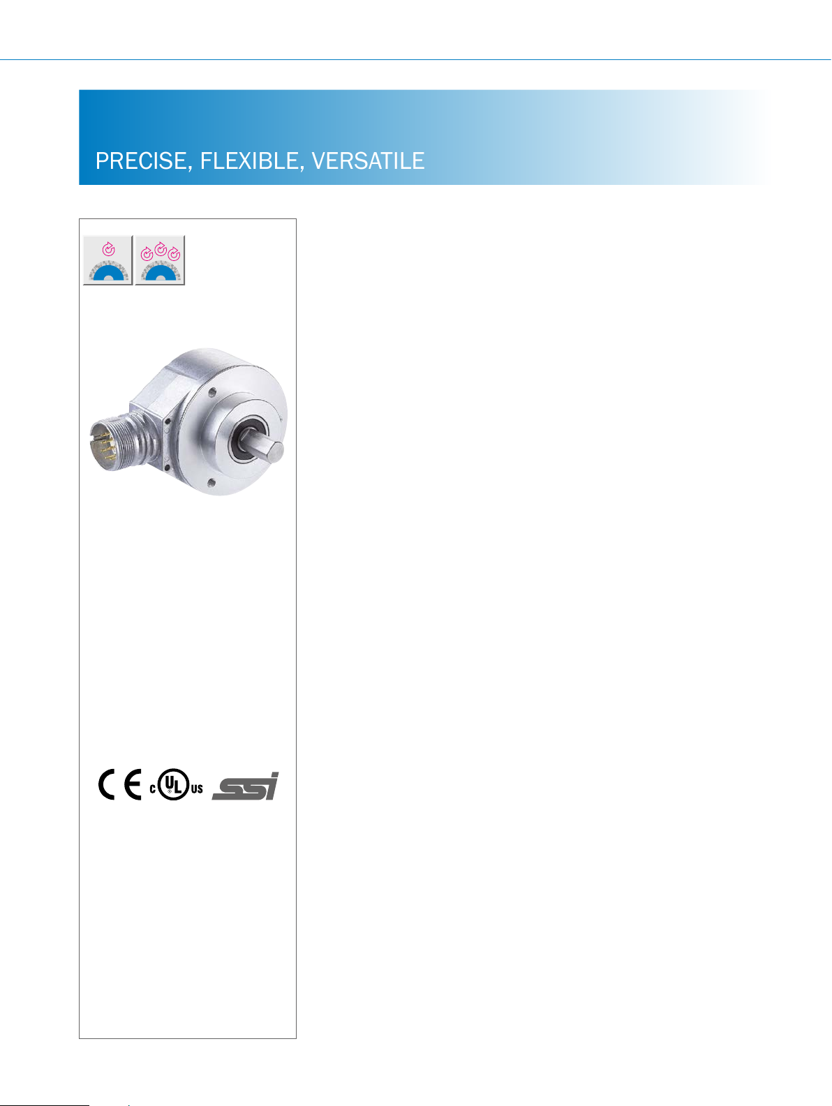
AFS/AFM60 SSI ABSOLUTE ENCODERS
PRECISE, FLEXIBLE, VERSATILE
Product description
With a high resolution of 18 bits (AFS60)
or 30 bits (AFM60) and a large selection
of programmable parameters, the AFS60
absolute singleturn encoder and the
AFM60 absolute multiturn encoder set
new standards when it comes to rotary
encoders. The high resolution combined
with the high IP protection class enables
use in a multitude of industrial applications. Both encoders are equipped with
the SSI interface while the AFM60 is also
available with the SSI + Incremental and
SSI + Sin/Cos combined interfaces. A
shaft bearing distance of 30 mm means
the AFS60/AFM60 product family has
signicantly better rotation accuracy than
encoders with blocked ball bearings. Yet
despite their large bearing distance, the
AFS60/AFM60 have a compact design.
The AFS and AFM60 SSI can be programmed via the same PC-based
programming tool (PGT-08-S) or the
hand-held PGT-10-Pro programming tool.
G
More information
Fields of application . . . . . . . . . . .G-269
Detailed technical data. . . . . . . . .G-269
Viewing number of resolutions. . .G-273
Ordering information. . . . . . . . . . .G-274
Dimensional drawings . . . . . . . . .G-292
PIN assignment. . . . . . . . . . . . . . .G-302
Signal outputs ................G-304
Interfaces....................G-305
Recommended accessories. . . . .G-306
At a glance
• High-resolution absolute encoder
with up to 30 bits (AFM60) or 18 bits
(AFS60)
• Face mount ange, servo ange, blind
hollow shaft or through hollow shaft
• SSI, SSI + incremental or SSI + sin/
cos interface
• Resolution, offset, etc. can be pro-
grammed (depending on the type)
Your benets
• The programmability of the encoder
results in reduced storage, high machine availability, and easy installation
• Precise positioning thanks to high
resolutions
• Large selection of mechanical
‚
interfaces and electrical contacting
options: suitable for all applications
• Connectivity: M12 or M23 male con-
nector or cable outlet
• Enclosure rating: IP67 (housing), IP65
(shaft)
• Operating temperature:
–40 °C ... +100 °C (depending on
the type)
• Suitable for applications with limited
space (extremely short installation
depth of 30 mm)
• Excellent concentricity properties due
to long bearing distance
• Suitable programming tools are
available as accessories for every
application
G-268
ENCODERS | SICK 8015560/2015-09-01
Subject to change without notice
Page 2

Fields of application
• Measurement of absolute position using one or more
revolutions in various machines and systems such as tool
Detailed technical data
Performance
Max. number of steps per revolution (SSI
interface)
1)
Max. number of revolutions
Absolute singleturn 1
Absolute multiturn 4,096
Resolution
Absolute singleturn 12 bit 15 bit 18 bit
Absolute multiturn 12 x 12 bit 15 x 12 bit 18 x 12 bit
Error limits
Repeatability
Measurement increment deviation
1 ... 399 (steps per revolution) ± 0.2° ± 0.08° ± 0.04°
400 ... 40,000 (steps per revolution) ± 0.2° ± 0.01° ± 0.008°
> 40,000 (steps per revolution) – ± 0.002°
Measuring increment (360 °/ number of
steps per revolution)
Initialization time
Position forming time
1)
See maximum viewing number of resolutions
2)
Position can be read after this period.
4,096 32,768 262,144
± 0.2° ± 0.05° ± 0.03°
0.002°
0.09° 0.01° 0.014°
2)
50 ms
< 1 µs
ABSOLUTE ENCODERS AFS/AFM60 SSI
machines, packaging systems, wood processing machines,
presses, printing machines
Eco Basic Advanced
G
Subject to change without notice
ENCODERS | SICK8015560/2015-09-01
G-269
Page 3

AFS/AFM60 SSI ABSOLUTE ENCODERS
Interfaces
Electrical interface
Signal offset
Code type
Congurable code sequence
Measurement increment
360°/number of steps 0.09° 0.01° 0.0014°
Number of steps per revolution
AFS60 and AFM60
Number of revolutions (AFM60)
Measurement increment deviation
Number of steps per revolution
1 … 399 ± 0.2° ± 0.08° ± 0.04°
400 … 40,000 ± 0.2° ± 0.01° ± 0.008°
> 40,000 – ± 0.002°
Clock+, Clock–, Data+, Data–
SSI max. clock frequency 2 MHz,
and min. LOW level (Clock+): 500 ns
SET (electronic adjustment)
V/¯R (counting sequence when turning)
SSI
2.5 V ± 10%
Gray
CW/CCW
1)
4,096 32,768 262144
4,096
1 MHz 2 MHz 2 MHz
H active (L = 0 – 3 V; H = 4 – US V)
L active (L = 0 – 1.5 V; H = 2.0 – US V)
Eco Basic Advanced
G
Incremental interface TTL/HTL/programmable (AFM60 SSI + incremental)
Number of lines per revolution
Measurement increment
1/4 of number of SSI steps per revolution
90° electric/number of lines
Measurement increment deviation
Number of steps per revolution 1 ... 99 ± 0.2° ± 0.08° ± 0.04°
Number of steps per revolution 100 ... 10,000 ± 0.2° ± 0.01° ± 0.008°
Number of steps per revolution > 10,000 – ± 0.002°
Interface signals A, ¯A, B, ¯B
Max. output frequency
Load current
Digital, differential
300 kHz 600 kHz 820 kHz
30 mA
Incremental interface sine/cosine
4.5 V … 5.5 V, sine 0.5 VSS
(AFM60 SSI + sin/cos)
Number of lines per revolution
Max. output frequency
Load resistance
Interface signals
1,024
200 kHz
Min. 120 Ω
Analog, differential
Sin+, Sin–, Cos+, Cos–
Signal before difference at 120 Ω load
Signal offset before differential generation
Signal after difference at 120 Ω load
1)
See maximum viewing number of resolutions
0.5 VPP ± 20%
2.5 V ± 10%
1 VSS ± 20 %
G-270
ENCODERS | SICK 8015560/2015-09-01
Subject to change without notice
Page 4

ABSOLUTE ENCODERS AFS/AFM60 SSI
Electrical data
Eco Basic Advanced
Connection type
Power consumption
Operating voltage range
Min. load resistance
Maximum output frequency
Code type
Code sequence
Reverse polarity protection
MTTFd: mean time to dangerous failure
1)
The universal cable outlet is positioned so that it is possible to lay it without bends in a radial or axial direction.
2)
No UL certicate.
3)
This product is a standard product and does not constitute a safety component as dened in the Machinery Directive. Calculation based on nominal load of devices,
average ambient temperature 40 °C, frequency of use 8,760 h/a. All electronic failures are considered hazardous. For more information, see document no.
8015532.
M23 male connector, 12-pin, radial
M12 male connector, 8-pin, radial
Cable, 8-wire, universal, 1.5 m
Cable, 8-wire, universal, 3 m
Cable, 8-wire, universal, 5 m
Cable, 8-wire, universal, 10 m
Cable, 12-wire, radial, 1.5 m
Cable, 12-wire, radial, 3 m
Cable, 12-wire, radial, 5 m
1)
1)
1)
1)
2)
2)
2)
0.5 W (without load)
4.5 V DC ... 32 V DC
– ≥ 120 Ω
– ≤ 200 kHz
Gray
CW/CCW, congurable
l
250 years (EN ISO 13849-1)
3)
Mechanical data
Eco Basic Advanced
Shaft diameter
Face mount ange 10 mm x 19 mm
Servo ange 6 mm x 10 mm
Blind hollow shaft, through hollow shaft 8, 10, 12, 14, 15 mm and 3/8", 1/2", 5/8"
Shaft material Stainless steel
Flange material Aluminum
Housing material Aluminum die-cast
2)
Mass
Face mount ange, servo ange 0.3 kg
Blind hollow shaft, through hollow shaft 0.2 kg
Start up torque at 20 °C
Face mount ange, servo ange 0.5 Ncm
Blind hollow shaft, through hollow shaft 0.8 Ncm
Operating torque at 20 °C
Face mount ange, servo ange 0.3 Ncm
Blind hollow shaft, through hollow shaft 0.6 Ncm
Permissible shaft movement, axial static/
dynamic
Blind hollow shaft, through hollow shaft ± 0.5 mm, ± 0.2 mm ± 0.5 mm, ± 0.1 mm
1)
5/8" not available for multiturn.
2)
Relates to devices with cable outlet.
3)
Take into account self-warming of 3.3 K per 1,000 rpm when designing operating temperature range
1)
G
Subject to change without notice
ENCODERS | SICK8015560/2015-09-01
G-271
Page 5

AFS/AFM60 SSI ABSOLUTE ENCODERS
Eco Basic Advanced
Permissible shaft movement, radial static/
dynamic
Blind hollow shaft, through hollow shaft ± 0.3 mm/ ± 0.1 mm ± 0.3 mm/ ± 0.05 mm
Permissible shaft loading
Face mount ange, servo ange 80 N (radial)
40 N (axial)
Maximum operating speed
Face mount ange, servo ange 9,000 rpm
Rotor moment of inertia
Face mount ange, servo ange 6.2 gcm²
Blind hollow shaft, through hollow shaft 40 gcm²
Bearing lifetime
Max. angular acceleration
1)
5/8" not available for multiturn.
2)
Relates to devices with cable outlet.
3)
Take into account self-warming of 3.3 K per 1,000 rpm when designing operating temperature range
3)
Blind hollow shaft 6,000 rpm
Through hollow shaft 9,000 rpm
3.0 x 10⁹ revolutions
≤ 500,000 rad/s²
G
Ambient data
Eco Basic Advanced
EMC
Enclosure rating
On the shaft IP 65
On the housing, male connector outlet
On the housing, cable outlet IP 67
Permissible relative humidity
Operating temperature range
Storage temperature range
Resistance to shocks (according to
EN 60068-2-27)
Resistance to vibration (according to
EN 60068-2-6)
1)
The EMC according to the standards quoted is achieved if shielded cables are used.
2)
In an assembled male connector.
3)
When cables are xed in place.
According to EN 61000-6–2 and EN 61000-6–3
2)
IP 67
90% (condensation of optical surfaces not permitted)
0 °C ... +85 °C –40 °C 3) ... +100 °C
–40 °C ... +100 °C, without packaging
50 g/ 6 ms 70 g/ 6 ms 60 g/ 6 ms
20 g/ 10 Hz ... 2,000 Hz 30 g/ 10 Hz ... 2,000 Hz 20 g/ 10 Hz ... 2,000 Hz
1)
G-272
ENCODERS | SICK 8015560/2015-09-01
Subject to change without notice
Page 6
ABSOLUTE ENCODERS AFS/AFM60 SSI
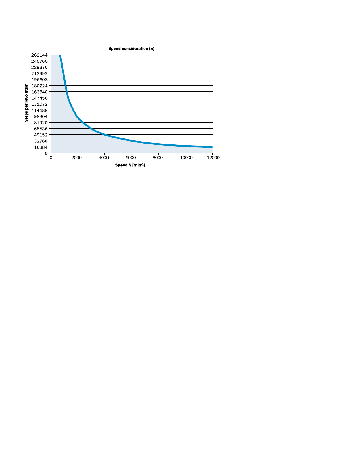
Maximum viewing number of resolutions depends on the selected number of steps per revolution
The maximum speed depends on the type of shaft.
G
Subject to change without notice
ENCODERS | SICK8015560/2015-09-01
G-273
Page 7
AFS/AFM60 SSI ABSOLUTE ENCODERS
Ordering information
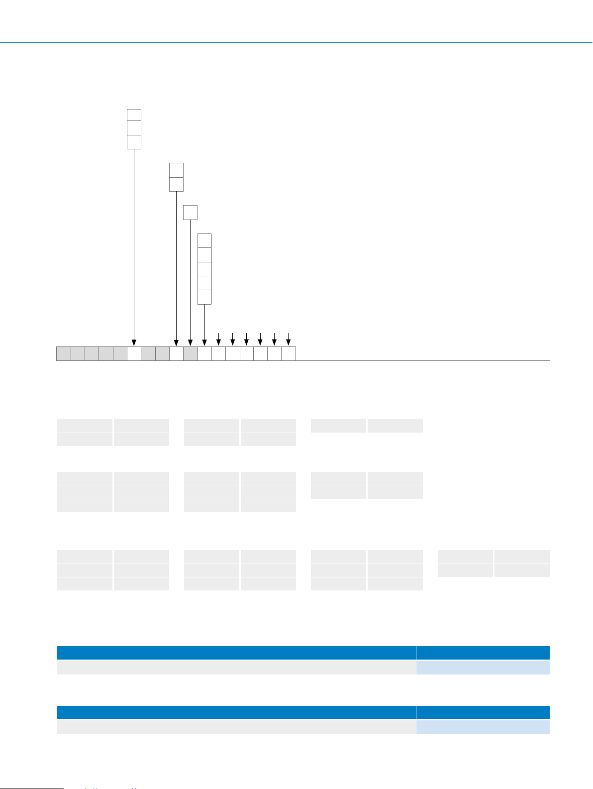
Type code AFS60 SSI absolute encoder, singleturn, solid shaft
Type
Type E (see technical data on page G-269)
E
Type B (see technical data on page G-269)
B
Type A (see technical data on page G-269)
A
Mechanical design
Servo ange, solid shaft, 6 x 10 mm
1
Face mount ange, solid shaft, 10 x 19 mm
4
Electrical interface
4.5 … 32 V SSI/Gray
A
Connection type
Male connector M23, 12-pin, radial
A
Male connector M12, 8-pin, radial
C
Cable, 8-wire, universal, 1.5 m
K
Cable, 8-wire, universal, 3 m
L
Cable, 8-wire, universal, 5 m
M
Resolution
Number of steps per revolution, selection depends on type, see below.
1)
1)
1)
G
A F S 6 0 – S A
1)
The universal cable outlet is positioned so that it is possible to lay it without bends in a radial or axial direction.
Number of steps per revolution
• Type E
000256 8 bit
000512 9 bit
• Type B
000256 8 bit
000512 9 bit
001024 10 bit
1)
Others available on request.
• Type A
000256 8 bit
000512 9 bit
001024 10 bit
1)
Others available on request.
1)
001024 10 bit
002048 11 bit
1)
002048 11 bit
004096 12 bit
008192 13 bit
1)
002048 11 bit
004096 12 bit
008192 13 bit
004096 12 bit
016384 14 bit
032768 15 bit
016384 14 bit
032768 15 bit
065536 16 bit
Example orders
• Servo ange
131072 17 bit
262144 18 bit
Type E, M12 male connector, 8-pin , radial, number of steps per revolution 1,024 (10 bit) AFS60E-S1AC001024
• Face mount ange
Type E, M12 male connector, 8-pin , radial, number of steps per revolution 1,024 (10 bit) AFS60E-S4AC001024
G-274
ENCODERS | SICK 8015560/2015-09-01
Servo ange design Type
Face mount ange design Type
Subject to change without notice
Page 8
ABSOLUTE ENCODERS AFS/AFM60 SSI
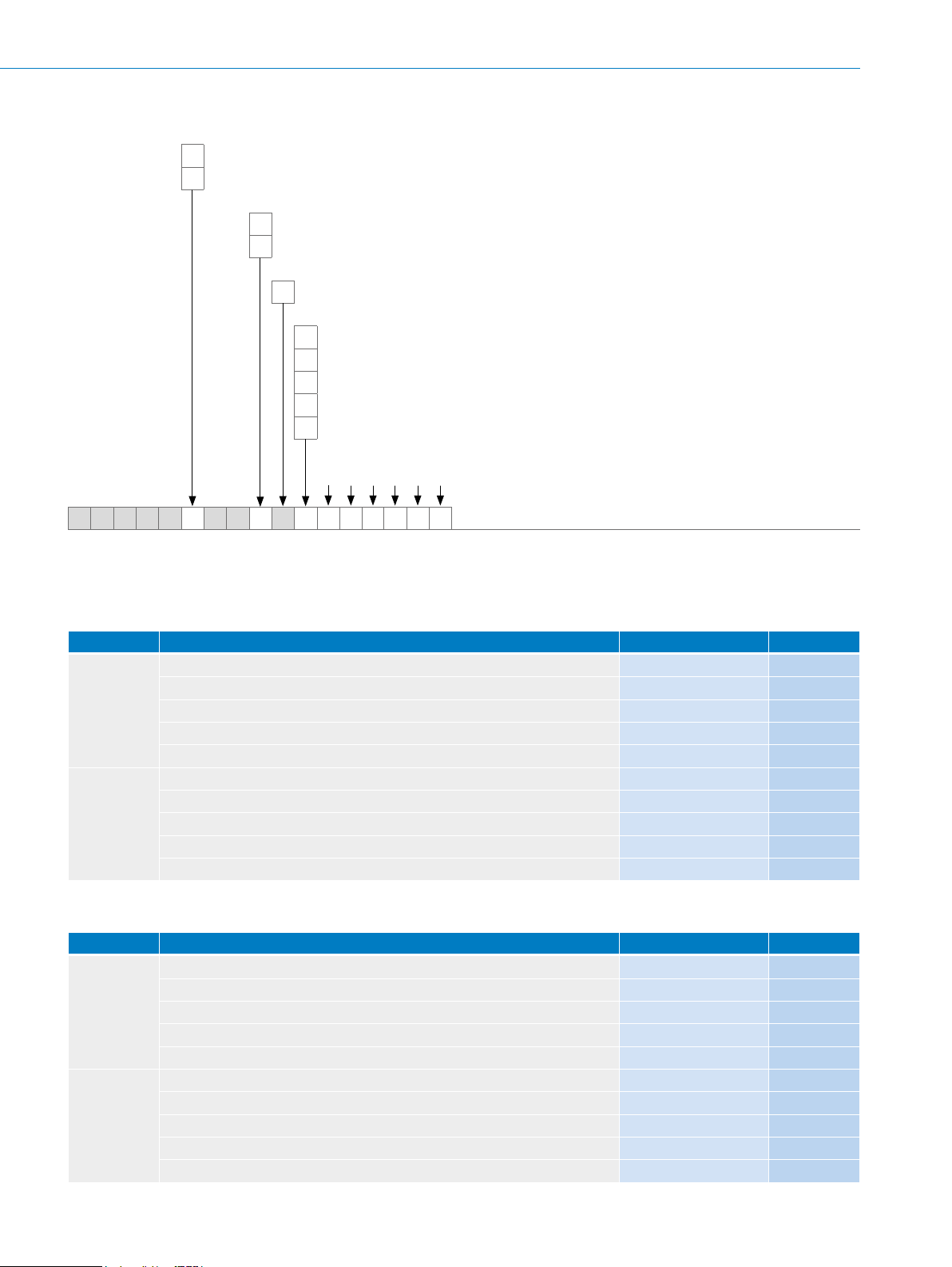
Type code AFS60 SSI absolute encoder, singleturn, solid shaft, programmable
Type
Type B (see technical data on page G-269)
B
Type A (see technical data on page G-269)
A
Mechanical design
Servo ange, solid shaft, 6 x 10 mm
1
Face mount ange, solid shaft, 10 x 19 mm
4
Electrical interface
4.5 … 32 V, SSI/Gray, programmable
P
Connection type
Male connector M23, 12-pin, radial
A
Male connector M12, 8-pin, radial
C
Cable, 8-wire, universal, 1.5 m
K
Cable, 8-wire, universal, 3 m
L
Cable, 8-wire, universal, 5 m
M
Resolution
Number of steps per revolution
1)
2)
2)
2)
1)
A F S 6 0 – S P
1)
Number of steps from 256 to 262144 can be programmed by the customer. Factory setting for Type B: 032768; Type A: 262144.
2)
The universal cable outlet is positioned so that it is possible to lay it without bends in a radial or axial direction.
Example orders
• Servo ange
Servo ange design Type Part no.
M23 male connector, 12-pin, radial, number of steps per revolution 32,768 AFS60B-S1PA032768 1037493
M12 male connector, 8-pin, radial, number of steps per revolution 32,768 AFS60B-S1PC032768 1037494
Type B
Type A
Cable, 8-wire, universal, 1.5 m, number of steps per revolution 32,768 AFS60B-S1PK032768 1037495
Cable, 8-wire, universal, 3 m, number of steps per revolution 32,768 AFS60B-S1PL032768 1037496
Cable, 8-wire, universal, 5 m, number of steps per revolution 32,768 AFS60B-S1PM032768 1037497
M23 male connector, 12-pin , radial, number of steps per revolution 262144 AFS60A-S1PA262144 1037498
M12 male connector, 8-pin, radial, number of steps per revolution 262144 AFS60A-S1PC262144 1037499
Cable, 8-wire, universal, 1.5 m, number of steps per revolution 262144 AFS60A-S1PK262144 1037500
Cable, 8-wire, universal, 3 m, number of steps per revolution 262144 AFS60A-S1PL262144 1037501
Cable, 8-wire, universal, 5 m, number of steps per revolution 262144 AFS60A-S1PM262144 1037502
• Face mount ange
Face mount ange design Type Part no.
M23 male connector, 12-pin, radial, number of steps per revolution 32,768 AFS60B-S4PA032768 1037483
M12 male connector, 8-pin, radial, number of steps per revolution 32,768 AFS60B-S4PC032768 1037484
Type B
Type A
Cable, 8-wire, universal, 1.5 m, number of steps per revolution 32,768 AFS60B-S4PK032768 1037485
Cable, 8-wire, universal, 3 m, number of steps per revolution 32,768 AFS60B-S4PL032768 1037486
Cable, 8-wire, universal, 5 m, number of steps per revolution 32,768 AFS60B-S4PM032768 1037487
M23 male connector, 12-pin , radial, number of steps per revolution 262144 AFS60A-S4PA262144 1037488
M12 male connector, 8-pin, radial, number of steps per revolution 262144 AFS60A-S4PC262144 1037489
Cable, 8-wire, universal, 1.5 m, number of steps per revolution 262144 AFS60A-S4PK262144 1037490
Cable, 8-wire, universal, 3 m, number of steps per revolution 262144 AFS60A-S4PL262144 1037491
Cable, 8-wire, universal, 5 m, number of steps per revolution 262144 AFS60A-S4PM262144 1037492
G
Subject to change without notice
ENCODERS | SICK8015560/2015-09-01
G-275
Page 9
AFS/AFM60 SSI ABSOLUTE ENCODERS
Type code AFM60 SSI/gray absolute encoder, multiturn, 4,096 revolutions, solid shaft
Type
Type E (see technical data on page G-269)
E
Type B (see technical data on page G-269)
B
Type A (see technical data on page G-269)
A
Mechanical design
Servo ange, solid shaft, 6 x 10 mm
1
Face mount ange, solid shaft, 10 x 19 mm
4
Electrical interface
4.5 … 32 V SSI/Gray
A
Connection type
Male connector M23, 12-pin, radial
A
Male connector M12, 8-pin, radial
C
Cable, 8-wire, universal, 1.5 m
K
Cable, 8-wire, universal, 3 m
L
Cable, 8-wire, universal, 5 m
M
Resolution
Number of steps per revolution, selection depends on type, see below.
1)
1)
1)
G
A F M 6 0 – S A
1)
The universal cable outlet is positioned so that it is possible to lay it without bends in a radial or axial direction.
Number of steps per revolution x 4,096 (12 bit)
• Type E
000256 8 bit
000512 9 bit
001024 10 bit
002048 11 bit
004096 12 bit
• Type B
000256 8 bit
000512 9 bit
001024 10 bit
002048 11 bit
004096 12 bit
008192 13 bit
016384 14 bit
032768 15 bit
• Type A
000256 8 bit
000512 9 bit
001024 10 bit
002048 11 bit
004096 12 bit
008192 13 bit
016384 14 bit
032768 15 bit
065536 16 bit
Example orders
• Servo ange
Servo ange design Type
Type E, cable, 8-wire, universal, 1.5 m, number of steps per revolution 4,096 (12 bits) AFM60E-S1AK004096
131072 17 bit
262144 18 bit
• Face mount ange
Type E, cable, 8-wire, universal, 1.5 m, number of steps per revolution 4,096 (12 bits) AFM60E-S4AK004096
G-276
ENCODERS | SICK 8015560/2015-09-01
Face mount ange design Type
Subject to change without notice
Page 10
ABSOLUTE ENCODERS AFS/AFM60 SSI
Type code AFM60 SSI/gray + incremental and SSI/gray + sin/cos, absolute encoder, multiturn, 4,096 revolutions, solid shaft
Type
Type E (see technical data on page G-269)
E
Type B (see technical data on page G-269)
B
Type A (see technical data on page G-269)
A
Mechanical design
Servo ange, solid shaft, 6 x 10 mm
1
Face mount ange, solid shaft, 10 x 19 mm
4
Electrical interface
4.5 … 32 V, SSI/Gray + incremental, HTL
L
4.5 … 32 V, SSI/Gray + incremental, TTL
T
4.5 … 32 V, SSI/Gray + Sin/Cos, 1,024 periods
K
Connection type
Male connector M23, 12-pin, radial
A
Cable, 12-wire, radial, 1.5 m
K
Cable, 12-wire, radial, 3.0 m
L
Cable, 12-wire, radial, 5.0 m
M
Resolution
Number of steps per revolution, selection depends on type, see below.
A F M 6 0 – S
Number of steps per revolution x 4,096 (12 bit), number of incremental lines in brackets
• Type E
000256 8 bit (64)
000512 9 bit (128)
001024 10 bit (256)
002048 11 bit (512)
004096 12 bit (1024)
• Type B
000256 8 bit (64)
000512 9 bit (128)
001024 10 bit (256)
002048 11 bit (512)
004096 12 bit (1024)
008192 13 bit (2048)
016384 14 bit (4096)
032768 15 bit (8192)
• Type A
000256 8 bit (64)
000512 9 bit (128)
001024 10 bit (256)
002048 11 bit (512)
004096 12 bit (1024)
008192 13 bit (2048)
016384 14 bit (4096)
032768 15 bit (8192)
065536 16 bit (16384)
Example orders
• Servo ange
Servo ange design Type
Type E, 4.5 ... 32 V, SSI/gray + incremental, TTL, M23 male connector, 12-pin , radial, number of steps per revolu-
tion 2,048 (11 bit)
G
131072 17 bit (32768)
262144 18 bit (65536)
AFM60E-S1TA002048
• Face mount ange
Face mount ange design Type
Type E, 4.5 ... 32 V, SSI/gray + incremental, TTL, M23 male connector, 12-pin , radial, number of steps per revolu-
tion 2,048 (11 bit)
Subject to change without notice
AFM60E-S4TA002048
ENCODERS | SICK8015560/2015-09-01
G-277
Page 11
AFS/AFM60 SSI ABSOLUTE ENCODERS
Type code AFM60 SSI/gray absolute encoder, multiturn, 4,096 revolutions, solid shaft, programmable
Type
Type B (see technical data on page G-269)
B
Type A (see technical data on page G-269)
A
Mechanical design
Servo ange, solid shaft, 6 x 10 mm
1
Face mount ange, solid shaft, 10 x 19 mm
4
Electrical interface
4.5 … 32 V, SSI/Gray, programmable
P
Connection type
Male connector M23, 12-pin, radial
A
Male connector M12, 8-pin, radial
C
Cable, 8-wire, universal, 1.5 m
K
Cable, 8-wire, universal, 3 m
L
Cable, 8-wire, universal, 5 m
M
Resolution
Number of steps per revolution
1)
2)
2)
2)
1)
G
A F M 6 0 – S P
1)
Number of steps from 256 (8 bit) to 262144 (18 bit) can be programmed by the customer. Factory setting for Type B: 032768; Type A: 262144.
2)
The universal cable outlet is positioned so that it is possible to lay it without bends in a radial or axial direction.
Example orders
• Servo ange
Servo ange design Type Part no.
M23 male connector, 12-pin, radial, number of steps per revolution 32,768 AFM60B-S1PA032768 1037513
M12 male connector, 8-pin, radial, number of steps per revolution 32,768 AFM60B-S1PC032768 1037514
Type B
Type A
Cable, 8-wire, universal, 1.5 m, number of steps per revolution 32,768 AFM60B-S1PK032768 1037515
Cable, 8-wire, universal, 3 m, number of steps per revolution 32,768 AFM60B-S1PL032768 1037516
Cable, 8-wire, universal, 5 m, number of steps per revolution 32,768 AFM60B-S1PM032768 1037517
M23 male connector, 12-pin , radial, number of steps per revolution 262144 AFM60A-S1PA262144 1037518
M12 male connector, 8-pin, radial, number of steps per revolution 262144 AFM60A-S1PC262144 1037519
Cable, 8-wire, universal, 1.5 m, number of steps per revolution 262144 AFM60A-S1PK262144 1037520
Cable, 8-wire, universal, 3 m, number of steps per revolution 262144 AFM60A-S1PL262144 1037521
Cable, 8-wire, universal, 5 m, number of steps per revolution 262144 AFM60A-S1PM262144 1037522
• Face mount ange
Face mount ange design Type Part no.
M23 male connector, 12-pin, radial, number of steps per revolution 32,768 AFM60B-S4PA032768 1037503
M12 male connector, 8-pin, radial, number of steps per revolution 32,768 AFM60B-S4PC032768 1037504
Type B
Type A
Cable, 8-wire, universal, 1.5 m, number of steps per revolution 32,768 AFM60B-S4PK032768 1037505
Cable, 8-wire, universal, 3 m, number of steps per revolution 32,768 AFM60B-S4PL032768 1037506
Cable, 8-wire, universal, 5 m, number of steps per revolution 32,768 AFM60B-S4PM032768 1037507
M23 male connector, 12-pin , radial, number of steps per revolution 262144 AFM60A-S4PA262144 1037508
M12 male connector, 8-pin, radial, number of steps per revolution 262144 AFM60A-S4PC262144 1037509
Cable, 8-wire, universal, 1.5 m, number of steps per revolution 262144 AFM60A-S4PK262144 1037510
Cable, 8-wire, universal, 3 m, number of steps per revolution 262144 AFM60A-S4PL262144 1037511
Cable, 8-wire, universal, 5 m, number of steps per revolution 262144 AFM60A-S4PM262144 1037512
G-278
ENCODERS | SICK 8015560/2015-09-01
Subject to change without notice
Page 12
ABSOLUTE ENCODERS AFS/AFM60 SSI
Type code AFM60 SSI/gray + incremental and SSI/gray + sin/cos, absolute encoder, multiturn, 4,096 revolutions, solid shaft, programmable
Type
Type B (see technical data on page G-269)
B
Type A (see technical data on page G-269)
A
Mechanical design
Servo ange, solid shaft, 6 x 10 mm
1
Face mount ange, solid shaft, 10 x 19 mm
4
Electrical interface
4.5 … 32 V, SSI/Gray + incremental, programmable
R
4.5 … 32 V, SSI/Gray programmable + sin/cos, 1,024 periods
S
Connection type
Male connector M23, 12-pin, radial
A
Cable, 12-wire, radial, 1.5 m
K
Cable, 12-wire, radial, 3.0 m
L
Cable, 12-wire, radial, 5.0 m
M
Resolution
Number of steps per revolution
1)
1)
1)
A F M 6 0 – S
1)
Number of steps from 256 (8 bit) to 262144 (18 bit) can be programmed by the customer. Factory setting for Type B: 032768; Type A: 262144. Number of incremen-
tal lines is always 1/4 of the number of SSI/gray lines.
Example orders
• Servo ange
Servo ange design Type Part no.
Type B
Type A
Type B
Type A
4.5 ... 32 V, SSI/gray + incremental, programmable, M23 male connector, 12pin, radial, number of steps per revolution 32,768
4.5 ... 32 V, SSI/gray + incremental, programmable, M23 male connector, 12-
pin , radial, number of steps per revolution 262144
4.5 ... 32 V, SSI/gray, programmable, + sin/cos, 1,024 periods, M23 male connector, 12-pin, radial, number of steps per revolution 32,768
4.5 ... 32 V, SSI/gray, programmable, + sin/cos, 1,024 periods, M23 male con-
nector, 12-pin , radial, number of steps per revolution 262144
AFM60B-S1RA032768 1052835
AFM60A-S1RA262144 1052837
AFM60B-S1SA032768 1054220
AFM60A-S1SA262144 1054219
• Face mount ange
Face mount ange design Type Part no.
Type B
Type A
Type B
Type A
4.5 ... 32 V, SSI/gray + incremental, programmable, M23 male connector, 12pin, radial, number of steps per revolution 32,768
4.5 ... 32 V, SSI/gray + incremental, programmable, M23 male connector, 12-
pin , radial, number of steps per revolution 262144
4.5 ... 32 V, SSI/gray, programmable, + sin/cos, 1,024 periods, M23 male connector, 12-pin, radial, number of steps per revolution 32,768
4.5 ... 32 V, SSI/gray, programmable, + sin/cos, 1,024 periods, M23 male con-
nector, 12-pin , radial, number of steps per revolution 262144
AFM60B-S4RA032768 1052833
AFM60A-S4RA262144 1052624
AFM60B-S4SA032768 1054222
AFM60A-S4SA262144 1054221
G
Subject to change without notice
ENCODERS | SICK8015560/2015-09-01
G-279
Page 13
AFS/AFM60 SSI ABSOLUTE ENCODERS
Type code AFS60 SSI absolute encoder, singleturn, hollow shaft
Type
Type E (see technical data on page G-269)
E
Type B (see technical data on page G-269)
B
Type A (see technical data on page G-269)
A
Mechanical design
Blind hollow shaft
B
Through hollow shaft
T
Hollow shaft diameter 8 mm
B
Hollow shaft diameter 3/8"
C
Hollow shaft diameter 10 mm
D
Hollow shaft diameter 12 mm
E
Hollow shaft diameter 1/2"
F
Hollow shaft diameter 14 mm
G
Hollow shaft diameter 15 mm
H
Hollow shaft diameter 5/8"
J
Electrical interface
4.5 … 32 V SSI/Gray
A
Connection type
Male connector M23, 12-pin, radial
A
Male connector M12, 8-pin, radial
C
Cable, 8-wire, universal, 1.5 m
K
Cable, 8-wire, universal, 3 m
L
Cable, 8-wire, universal, 5 m
M
Resolution
Number of steps per revolution, selection depends on type, see below.
1)
1)
1)
G
A F S 6 0 – A
1)
The universal cable outlet is positioned so that it is possible to lay it without bends in a radial or axial direction.
Number of steps per revolution
• Type E
000256 8 bit
000512 9 bit
• Type B
000256 8 bit
000512 9 bit
001024 10 bit
1)
Others available on request.
• Type A
000256 8 bit
000512 9 bit
001024 10 bit
1)
Others available on request.
1)
001024 10 bit
002048 11 bit
1)
002048 11 bit
004096 12 bit
008192 13 bit
1)
002048 11 bit
004096 12 bit
008192 13 bit
004096 12 bit
016384 14 bit
032768 15 bit
016384 14 bit
032768 15 bit
065536 16 bit
131072 17 bit
262144 18 bit
G-280
ENCODERS | SICK 8015560/2015-09-01
Subject to change without notice
Page 14

ABSOLUTE ENCODERS AFS/AFM60 SSI
Example orders
• Blind hollow shaft
Blind hollow shaft design Type
Type E, hollow shaft design 8 mm, M12 male connector, 8-pin , radial, number of steps per revolution 1,024 (10 bit) AFS60E-BBAC001024
• Through hollow shaft
Through hollow shaft design Type
Type E, hollow shaft design 8 mm, M12 male connector, 8-pin , radial, number of steps per revolution 1,024 (10 bit) AFS60E-TBAC001024
G
Subject to change without notice
ENCODERS | SICK8015560/2015-09-01
G-281
Page 15

AFS/AFM60 SSI ABSOLUTE ENCODERS
Type code AFS60 SSI absolute encoder, singleturn, hollow shaft, programmable
Type
Type B (see technical data on page G-269)
B
Type A (see technical data on page G-269)
A
Mechanical design
Blind hollow shaft
B
Through hollow shaft
T
Hollow shaft diameter 8 mm
B
Hollow shaft diameter 3/8"
C
Hollow shaft diameter 10 mm
D
Hollow shaft diameter 12 mm
E
Hollow shaft diameter 1/2"
F
Hollow shaft diameter 14 mm
G
Hollow shaft diameter 15 mm
H
Hollow shaft diameter 5/8"
J
Electrical interface
4.5 … 32 V SSI/Gray
P
Connection type
Male connector M23, 12-pin, radial
A
Male connector M12, 8-pin, radial
C
Cable, 8-wire, universal, 1.5 m
K
Cable, 8-wire, universal, 3 m
L
Cable, 8-wire, universal, 5 m
M
Resolution
Number of steps per revolution
1)
2)
2)
2)
1)
G
A F S 6 0 – P
1)
Number of steps from 256 to 262144 can be programmed by the customer. Factory setting for Type B: 032768; Type A: 262144.
2)
The universal cable outlet is positioned so that it is possible to lay it without bends in a radial or axial direction.
G-282
ENCODERS | SICK 8015560/2015-09-01
Subject to change without notice
Page 16

ABSOLUTE ENCODERS AFS/AFM60 SSI
Example orders
1)
• Blind hollow shaft
Blind hollow shaft design Type
M23 male connector, 12-pin, radial, number of steps per revolution 32,768 AFS60B-BxPA032768
Type B
Type A
1)
x stands for hollow shaft diameters B to J, please enter corresponding letters in position 9.
M12 male connector, 8-pin, radial, number of steps per revolution 32,768 AFS60B-BxPC032768
Cable, 8-wire, universal, 1.5 m, number of steps per revolution 32,768 AFS60B-BxPK032768
M23 male connector, 12-pin , radial, number of steps per revolution 262144 AFS60A-BxPA262144
M12 male connector, 8-pin, radial, number of steps per revolution 262144 AFS60A-BxPC262144
Cable, 8-wire, universal, 1.5 m, number of steps per revolution 262144 AFS60A-BxPK262144
• Through hollow shaft
Through hollow shaft design Type
M23 male connector, 12-pin, radial, number of steps per revolution 32,768 AFS60B-TxPA032768
Type B
Type A
1)
x stands for hollow shaft diameters B to J, please enter corresponding letters in position 9.
M12 male connector, 8-pin, radial, number of steps per revolution 32,768 AFS60B-TxPC032768
Cable, 8-wire, universal, 1.5 m, number of steps per revolution 32,768 AFS60B-TxPK032768
M23 male connector, 12-pin , radial, number of steps per revolution 262144 AFS60A-TxPA262144
M12 male connector, 8-pin, radial, number of steps per revolution 262144 AFS60A-TxPC262144
Cable, 8-wire, universal, 1.5 m, number of steps per revolution 262144 AFS60A-TxPK262144
G
Subject to change without notice
ENCODERS | SICK8015560/2015-09-01
G-283
Page 17

AFS/AFM60 SSI ABSOLUTE ENCODERS
Type code AFM60 SSI/gray absolute encoder, multiturn, 4,096 revolutions, hollow shaft
Type
Type E (see technical data on page G-269)
E
Type B (see technical data on page G-269)
B
Type A (see technical data on page G-269)
A
Mechanical design
Blind hollow shaft
B
Through hollow shaft
T
Hollow shaft diameter 8 mm
B
Hollow shaft diameter 3/8"
C
Hollow shaft diameter 10 mm
D
Hollow shaft diameter 12 mm
E
Hollow shaft diameter 1/2"
F
Hollow shaft diameter 14 mm
G
Hollow shaft diameter 15 mm
H
Electrical interface
4.5 … 32 V SSI/Gray
A
Connection type
Male connector M23, 12-pin, radial
A
Male connector M12, 8-pin, radial
C
Cable, 8-wire, universal, 1.5 m
K
Cable, 8-wire, universal, 3 m
L
Cable, 8-wire, universal, 5 m
M
Resolution
Number of steps per revolution, selection depends on type, see below.
1)
1)
1)
G
A F M 6 0 – A
1)
The universal cable outlet is positioned so that it is possible to lay it without bends in a radial or axial direction.
Number of steps per revolution x 4,096 (12 bit)
• Type E
000256 8 bit
000512 9 bit
001024 10 bit
002048 11 bit
004096 12 bit
• Type B
000256 8 bit
000512 9 bit
001024 10 bit
002048 11 bit
004096 12 bit
008192 13 bit
016384 14 bit
032768 15 bit
• Type A
000256 8 bit
000512 9 bit
001024 10 bit
002048 11 bit
004096 12 bit
008192 13 bit
016384 14 bit
032768 15 bit
065536 16 bit
131072 17 bit
262144 18 bit
G-284
ENCODERS | SICK 8015560/2015-09-01
Subject to change without notice
Page 18

ABSOLUTE ENCODERS AFS/AFM60 SSI
Example orders
• Blind hollow shaft
Blind hollow shaft design Type
Type E, hollow shaft diameter 8 mm cable, 8-wire, universal, 1.5 m, number of steps per revolution 4,096 (12 bits) AFM60E-BBAK004096
• Through hollow shaft
Through hollow shaft design Type
Type E, hollow shaft diameter 8 mm cable, 8-wire, universal, 1.5 m, number of steps per revolution 4,096 (12 bits) AFM60E-TBAK004096
G
Subject to change without notice
ENCODERS | SICK8015560/2015-09-01
G-285
Page 19

G
AFS/AFM60 SSI ABSOLUTE ENCODERS
Type code AFM60 SSI/gray + incremental and SSI/gray + sin/cos, absolute encoder, multiturn, 4,096 revolutions, hollow shaft
Type
Type E (see technical data on page G-269)
E
Type B (see technical data on page G-269)
B
Type A (see technical data on page G-269)
A
Mechanical design
Blind hollow shaft
B
Through hollow shaft
T
Hollow shaft diameter 8 mm
B
Hollow shaft diameter 3/8"
C
Hollow shaft diameter 10 mm
D
Hollow shaft diameter 12 mm
E
Hollow shaft diameter 1/2"
F
Hollow shaft diameter 14 mm
G
Hollow shaft diameter 15 mm
H
Electrical interface
4.5 … 32 V, SSI/Gray + incremental, HTL
L
4.5 … 32 V, SSI/Gray + incremental, TTL
T
4.5 … 32 V, SSI/Gray + Sin/Cos, 1,024 periods
K
Connection type
Male connector M23, 12-pin, radial
A
Cable, 12-wire, radial, 1.5 m
K
Cable, 12-wire, radial, 3.0 m
L
Cable, 12-wire, radial, 5.0 m
M
Resolution
Number of steps per revolution, selection depends on type, see below.
A F M 6 0 –
Number of steps per revolution x 4,096 (12 bit), number of incremental lines in brackets
• Type E
000256 8 bit (64)
000512 9 bit (128)
001024 10 bit (256)
002048 11 bit (512)
004096 12 bit (1024)
• Type B
000256 8 bit (64)
000512 9 bit (128)
001024 10 bit (256)
002048 11 bit (512)
004096 12 bit (1024)
008192 13 bit (2048)
016384 14 bit (4096)
032768 15 bit (8192)
• Type A
000256 8 bit (64)
000512 9 bit (128)
001024 10 bit (256)
G-286
ENCODERS | SICK 8015560/2015-09-01
002048 11 bit (512)
004096 12 bit (1024)
008192 13 bit (2048)
016384 14 bit (4096)
032768 15 bit (8192)
065536 16 bit (16384)
131072 17 bit (32768)
262144 18 bit (65536)
Subject to change without notice
Page 20

ABSOLUTE ENCODERS AFS/AFM60 SSI
Example orders
• Blind hollow shaft
Blind hollow shaft design Type
Type E, hollow shaft diameter 8 mm, 4.5 ... 32 V, SSI/gray + incremental, TTL, M23 male connector, 12-pin , radial,
number of steps per revolution 2,048 (11 bit)
• Through hollow shaft
Through hollow shaft design Type
Type E, hollow shaft diameter 8 mm, 4.5 ... 32 V, SSI/gray + incremental, TTL, M23 male connector, 12-pin , radial,
number of steps per revolution 2,048 (11 bit)
AFM60E-BBTA002048
AFM60E-TBTA002048
G
Subject to change without notice
ENCODERS | SICK8015560/2015-09-01
G-287
Page 21

AFS/AFM60 SSI ABSOLUTE ENCODERS
Type code AFM60 SSI/gray absolute encoder, multiturn, 4,096 revolutions, hollow shaft, programmable
Type
Type B (see technical data on page G-269)
B
Type A (see technical data on page G-269)
A
Mechanical design
Blind hollow shaft
B
Through hollow shaft
T
Hollow shaft diameter 8 mm
B
Hollow shaft diameter 3/8"
C
Hollow shaft diameter 10 mm
D
Hollow shaft diameter 12 mm
E
Hollow shaft diameter 1/2"
F
Hollow shaft diameter 14 mm
G
Hollow shaft diameter 15 mm
H
Electrical interface
4.5 … 32 V, SSI/Gray, programmable
P
Connection type
Male connector M23, 12-pin, radial
A
Male connector M12, 8-pin, radial
C
Cable, 8-wire, universal, 1.5 m
K
Cable, 8-wire, universal, 3 m
L
Cable, 8-wire, universal, 5 m
M
Resolution
Number of steps per revolution
1)
2)
2)
2)
1)
G
A F M 6 0 – P
1)
Number of steps from 256 (8 bit) to 262144 (18 bit) can be programmed by the customer. Factory setting for Type B: 032768; Type A: 262144.
2)
The universal cable outlet is positioned so that it is possible to lay it without bends in a radial or axial direction.
G-288
ENCODERS | SICK 8015560/2015-09-01
Subject to change without notice
Page 22

ABSOLUTE ENCODERS AFS/AFM60 SSI
Example orders
1)
• Blind hollow shaft
Blind hollow shaft design Type
M23 male connector, 12-pin, radial, number of steps per revolution 32,768 AFM60B-BxPA032768
Type B
Type A
1)
x stands for hollow shaft diameters B to H, please enter corresponding letters in position 9.
M12 male connector, 8-pin, radial, number of steps per revolution 32,768 AFM60B-BxPC032768
Cable, 8-wire, universal, 1.5 m, number of steps per revolution 32,768 AFM60B-BxPK032768
M23 male connector, 12-pin , radial, number of steps per revolution 262144 AFM60A-BxPA262144
M12 male connector, 8-pin, radial, number of steps per revolution 262144 AFM60A-BxPC262144
Cable, 8-wire, universal, 1.5 m, number of steps per revolution 262144 AFM60A-BxPK262144
• Through hollow shaft
Through hollow shaft design Type
M23 male connector, 12-pin, radial, number of steps per revolution 32,768 AFM60B-TxPA032768
Type B
Type A
1)
x stands for hollow shaft diameters B to H, please enter corresponding letters in position 9.
M12 male connector, 8-pin, radial, number of steps per revolution 32,768 AFM60B-TxPC032768
Cable, 8-wire, universal, 1.5 m, number of steps per revolution 32,768 AFM60B-TxPK032768
M23 male connector, 12-pin , radial, number of steps per revolution 262144 AFM60A-TxPA262144
M12 male connector, 8-pin, radial, number of steps per revolution 262144 AFM60A-TxPC262144
Cable, 8-wire, universal, 1.5 m, number of steps per revolution 262144 AFM60A-TxPK262144
G
Subject to change without notice
ENCODERS | SICK8015560/2015-09-01
G-289
Page 23

AFS/AFM60 SSI ABSOLUTE ENCODERS
Type code AFM60 SSI/gray + incremental and SSI/gray + sin/cos, absolute encoder, multiturn, 4,096 revolutions, hollow shaft, programmable
Type
Type B (see technical data on page G-269)
B
Type A (see technical data on page G-269)
A
Mechanical design
Blind hollow shaft
B
Through hollow shaft
T
Hollow shaft diameter 8 mm
B
Hollow shaft diameter 3/8"
C
Hollow shaft diameter 10 mm
D
Hollow shaft diameter 12 mm
E
Hollow shaft diameter 1/2"
F
Hollow shaft diameter 14 mm
G
Hollow shaft diameter 15 mm
H
Electrical interface
4.5 … 32 V, SSI/Gray + incremental, programmable
R
4.5 … 32 V, SSI/Gray programmable + sin/cos, 1,024 periods
S
Connection type
Male connector M23, 12-pin, radial
A
Cable, 12-wire, radial, 1.5 m
K
Cable, 12-wire, radial, 3.0 m
L
Cable, 12-wire, radial, 5.0 m
M
Resolution
Number of steps per revolution
1)
1)
1)
G
A F M 6 0 –
1)
Number of steps from 256 (8 bit) to 262144 (18 bit) can be programmed by the customer. Factory setting for Type B: 032768; Type A: 262144. Number of incremen-
tal lines is always 1/4 of the number of SSI/gray lines.
G-290
ENCODERS | SICK 8015560/2015-09-01
Subject to change without notice
Page 24

ABSOLUTE ENCODERS AFS/AFM60 SSI
Example orders
1)
• Blind hollow shaft
Blind hollow shaft design Type
Type B
Type A
Type B
Type A
1)
x stands for hollow shaft diameters B to H, please enter corresponding letters in position 9.
4.5 ... 32 V, SSI/gray + incremental, programmable, M23 male connector, 12-pin, radial, number
of steps per revolution 32,768
4.5 ... 32 V, SSI/gray + incremental, programmable, M23 male connector, 12-pin , radial, number
of steps per revolution 262144
4.5 ... 32 V, SSI/gray, programmable, + sin/cos, 1,024 periods, M23 male connector, 12-pin,
radial, number of steps per revolution 32,768
4.5 ... 32 V, SSI/gray, programmable, + sin/cos, 1,024 periods, M23 male connector, 12-pin ,
radial, number of steps per revolution 262144
• Through hollow shaft
Through hollow shaft design Type
Type B
Type A
Type B
Type A
1)
x stands for hollow shaft diameters B to H, please enter corresponding letters in position 9.
4.5 ... 32 V, SSI/gray + incremental, programmable, M23 male connector, 12-pin, radial, number
of steps per revolution 32,768
4.5 ... 32 V, SSI/gray + incremental, programmable, M23 male connector, 12-pin , radial, number
of steps per revolution 262144
4.5 ... 32 V, SSI/gray, programmable, + sin/cos, 1,024 periods, M23 male connector, 12-pin,
radial, number of steps per revolution 32,768
4.5 ... 32 V, SSI/gray, programmable, + sin/cos, 1,024 periods, M23 male connector, 12-pin ,
radial, number of steps per revolution 262144
AFM60B-BxRA032768
AFM60A-BxRA262144
AFM60B-BxSA032768
AFM60A-BxSA262144
AFM60B-TxRA032768
AFM60A-TxRA262144
AFM60B-TxSA032768
AFM60A-TxSA262144
G
Subject to change without notice
ENCODERS | SICK8015560/2015-09-01
G-291
Page 25

AFS/AFM60 SSI ABSOLUTE ENCODERS
Ø 0.05
C
A
Dimensional drawings (dimensions in mm)
Face mount ange
Universal cable outlet
A
(0.39)
±0.3
10
Ø 0.1
A
43.1 (1.70)
A
3 x 120°
Ø 60 (2.36)
Ø 0.05
B
C
18
(0.39) f7
(0.71)
9
(0.35)
19
0.03
Ø 36
(1.42) f8
Ø 10
B
A
General tolerances according to DIN ISO 2768-mk
1 Cable Ø = 5.6 mm ± 0.2 mm bend radius R = 30 mm
Radial cable outlet for AFM60 SSI + incremental and AFM60 SSI + sin/cos
3 x M4
(6-deep)
(1.89)
±0.05
Ø 48
G
10
18
±0.3
40.1
SW 14
A
Ø 60 (2.36)
±2
(0.69)
17.5
(1.42)
Ø 36 f8
0.03 A
Ø 0.05CB
(0.39)
Ø 10 f7
B
9
(0.39)
(0.71)
(0.35)
0.1 A
19
(0.75)
(1.58)
General tolerances according to DIN ISO 2768-mk
3 x 120°
25°
3 x M4
6 deep (0.24)
(1.89)
±0.05
Ø 48
Ø 0.1 C
±2°
G-292
ENCODERS | SICK 8015560/2015-09-01
Subject to change without notice
Page 26

M12 and M23 cable outlet
Ø 0.1
C
A
ABSOLUTE ENCODERS AFS/AFM60 SSI
18
(0.71)
±0.3
(0.75)
0.1
40.1 (1.58)
10
(0.39)
A
A
14.5
(0.57)
Ø 60 (2.36)
7.75
(0.31)
M12 x 1
26.1
0.03
Ø 36
(1.42) f8
Ø 10
B
A
Ø 0.05
(0.39) f7
B
C
19
9
(0.35)
General tolerances according to DIN ISO 2768-mk
(1.03)
M23 x 1
(3x) 120°
13
(0.51)
25°
±2°
3 x M4
(6-deep)
(1.89)
±0.05
Ø 48
G
Subject to change without notice
ENCODERS | SICK8015560/2015-09-01
G-293
Page 27

AFS/AFM60 SSI ABSOLUTE ENCODERS
5.
A
58
Servo ange
Universal cable outlet
A
(2.28)
±0.1
58
51.5–0.2 (2.03)
Ø 0.05
B
(0.12)
C
9.5
(0.37)
(0.24) f7
Ø 6
±0.3
10
B
Ø 50 (1.97) f8
(0.39)
7 (0.22)
3
+0.1
4
(0.16)
A
+0.1
10
(0.39)
43.1 (1.70)
0.1
0.1
A
A
3 x 120°
Ø 60 (2.36)
General tolerances according to DIN ISO 2768-mk
1 Cable Ø = 5.6 mm ± 0.2 mm bend radius R = 30 mm
Radial cable outlet for AFM60 SSI + incremental and AFM60 SSI + sin/cos
+0.1
4
(2.28)
±0.1
51.5–0.2 (2.03)
Ø 50 f8 (1.97)
Ø 0.05 B
C
(0.24)
Ø 6 f7
B
5.7
(0.16)
3
(0.12)
9.5
(0.37)
(0.22)
0.1 A
0.1 A
A
Ø 60 (2.36)
3 x 120°
Ø 0.05
3 x M4
(6-deep)
(1.65)
±0.05
Ø 42
C
3 x M4
6 deep (0.24)
(1.65)
±0.05
Ø 42
G
±0.3
0.03 A
10
(0.39)
10
(0.39)
+0.1
SW 14
7.75
40.1
(1.58)
(0.31)
General tolerances according to DIN ISO 2768-mk
±2
17.5
(0.69)
25°
±2°
Ø 0.1
C
G-294
ENCODERS | SICK 8015560/2015-09-01
Subject to change without notice
Page 28

M12 and M23 cable outlet
58
3 x 120°
4 x 90°
+0.1
4
(0.16)
A
(2.28)
±0.1
Ø 50 (1.97) f8
51.5–0.2 (2.03)
0.03
Ø 6
B
A
Ø 0.05
C
f7
(0.24)
(0.22)
5.7
9.5
(0.37)
10
(0.39)
B
±0.3
10
(0.12)
+0.1
(0.39)
3
14.5
M12 x 1
(1.58)
40.1
A
(0.57)
0.1
0.1
A
A
Ø 60 (2.36)
7.75
(0.31)
26.1
General tolerances according to DIN ISO 2768-mk
Mounting suggestion for small servo clamp
part number 2029166
(1.03)
M23 x 1
13
(0.51)
ABSOLUTE ENCODERS AFS/AFM60 SSI
3 x 120°
3 x M4
(6-deep)
(1.65)
±0.05
Ø 42
25°
±2°
C
Ø 0.1
Mounting suggestion for half-shell servo clamp
part number 2029165
Ø 68 (2.68)
General tolerances according to DIN ISO 2768-mk
Ø 71 (2.80)
G
Subject to change without notice
ENCODERS | SICK8015560/2015-09-01
G-295
Page 29

AFS/AFM60 SSI ABSOLUTE ENCODERS
47 (1.85)
A
Customer-side
Blind hollow shaft
Universal cable outlet
45.5
(1.79)
9.4
(0.37)
3.4 (0.13)
Ø X F7
Ø 35 (1.38)
Ø 60 (2.36)
2.5
(0.10)
+0.1
Ø 3.2
(0.13)
20°
20
(0.79)
(2.48)
(2.83)
±0.2
±0.3
72
Ø 63
G
Ø x j7
min. 15 (0.59)
max. 42 (1.65)
General tolerances according to DIN ISO 2768-mk
1 Cable Ø = 5.6 mm ± 0.2 mm bend radius R = 30 mm
XF7 = Encoder shaft diameter, see type code
xj7 = Shaft diameter, on the customer side
G-296
ENCODERS | SICK 8015560/2015-09-01
Subject to change without notice
Page 30

Radial cable outlet for AFM60 SSI + incremental and AFM60 SSI + sin/cos
A
Customer-side
45.5 (1.79)
9.4
(0.37)
Ø X F7
3.4
(0.13)
2.5
(0.10)
(1.28)
Ø 32.6
(2.36)
Ø 60
±2
17.5
(0.69)
20
(0.79)
72
±0.3
ABSOLUTE ENCODERS AFS/AFM60 SSI
(2.83)
+0.1
Ø 3.2
(0.13)
20°
7.75
(0.31)
Ø x j7
min. 15
(0.59)
max. 42
(1.65)
SW 14
General tolerances according to DIN ISO 2768-mk
XF7 = Encoder shaft diameter, see type code
xj7 = Shaft diameter, on the customer side
47 (1.85)
Ø 63
±0.2
(2.48)
G
Subject to change without notice
ENCODERS | SICK8015560/2015-09-01
G-297
Page 31

AFS/AFM60 SSI ABSOLUTE ENCODERS
20°
A
Customer-side
M12 and M23 cable outlet
45.5
(1.79)
9.4
(0.37)
2.5
3.4 (0.13)
Ø X F7
(0.10)
72
±0.3
Ø 3.2
(2.83)
+0.1
(0.13)
G
Ø 60 (2.36)
Ø 32.6 (1.28)
14.5
(0.57)
min. 15 (0.59)
max. 42 (1.65)
7.75
(0.31)
26.1 (1.03)
M12 x 1
Ø x j7
13
(0.51)
M23 x 1
General tolerances according to DIN ISO 2768-mk
XF7 = Encoder shaft diameter, see type code
xj7 = Shaft diameter, on the customer side
20 (0.79)
Ø 63
47 (1.85)
±0.2
(2.48)
G-298
ENCODERS | SICK 8015560/2015-09-01
Subject to change without notice
Page 32

Through hollow shaft
47 (1.85)
A
Customer-side
Universal cable outlet
ABSOLUTE ENCODERS AFS/AFM60 SSI
Ø X F7
43 (1.69)
9.4 (0.37)
3.4 (0.13)
min. 15 (0.59)
Ø 60 (2.36)
Ø x j7
+0.1
Ø 3.2
(0.13)
20°
20
(0.79)
(2.48)
(2.83)
±0.2
±0.3
72
Ø 63
General tolerances according to DIN ISO 2768-mk
1 Cable Ø = 5.6 mm ± 0.2 mm bend radius R = 30 mm
XF7 = Encoder shaft diameter, see type code
xj7 = Shaft diameter, on the customer side
G
Subject to change without notice
ENCODERS | SICK8015560/2015-09-01
G-299
Page 33

AFS/AFM60 SSI ABSOLUTE ENCODERS
A
Customer-side
Radial cable outlet for AFM60 SSI + incremental and AFM60 SSI + sin/cos
43 (1.69)
9.4
(0.37)
3.4
(0.13)
72
±0.3
(2.83)
Ø 3.2
(0.13)
+0.1
G
Ø X F7
SW 14
min. 15
(0.59)
(2.36)17.5
Ø 60
±2
(0.69)
7.75
(0.31)
Ø x j7
20
General tolerances according to DIN ISO 2768-mk
XF7 = Encoder shaft diameter, see type code
xj7 = Shaft diameter, on the customer side
(0.79)
Ø 63
47 (1.85)
±0.2
(2.48)
20°
G-300
ENCODERS | SICK 8015560/2015-09-01
Subject to change without notice
Page 34

M12 and M23 cable outlet
20°
A
Customer-side
43 (1.69)
9.4 (0.37)
3.4 (0.13)
Ø X F7
72
±0.3
Ø 3.2
ABSOLUTE ENCODERS AFS/AFM60 SSI
(2.83)
+0.1
(0.13)
Ø 60 (2.36)
7.75
(0.31)
14.5
(0.57)
26.1 (1.03)
M12 x 1
Ø x j7
min. 15 (0.59)
General tolerances according to DIN ISO 2768-mk
XF7 = Encoder shaft diameter, see type code
xj7 = Shaft diameter, on the customer side
13
(0.51)
M23 x 1
20 (0.79)
47 (1.85)
Ø 63
±0.2
(2.48)
G
Subject to change without notice
ENCODERS | SICK8015560/2015-09-01
G-301
Page 35

AFS/AFM60 SSI ABSOLUTE ENCODERS
PIN assignment
V/¯R Forwards/Reverse: This input programs the counting direction for the encoder. When it is not connected, this input is set to
HIGH. If the encoder shaft is rotated clockwise (to the right) as viewed when facing the shaft, it counts in ascending order.
If it should count in ascending order when the shaft is rotated counterclockwise (to the left), then this connection must be
permanently set to LOW level (GND).
SET This input is for electronic zeroing. If the SET cable is set to U
for at least 1,000 ms or had been connected to GND, the mechanical position corresponds to the O value, i.e., the predetermined SET value.
M12 male connector, 8-pin and
cable outlet, cable, 8-wire
SSI/gray
View of M12 male device connector on encoder
Pin Wire colors SSI signal Explanation
1 Brown Data– Interface signals
2 White Data+ Interface signals
3 Black V/¯R Sequence in direction of rotation
4 Pink SET Electronic adjustment
5 Yellow Clock+ Interface signals
6 Violet Clock - Interface signals
7 Blue GND Ground connection
8 Red +U
Screen Screen connected to housing on encoder side. Connected to ground on control side.
S
Operating voltage
for more than 250 ms after it had previously been unassigned
S
G
M23 male connector, 12-pin
SSI/gray
View of M23 male device connector on encoder
Pin Signal Explanation
1 GND Ground connection
2 Data+ Interface signals
3 Clock+ Interface signals
4 N. C. Not connected
5 N. C. Not connected
6 N. C. Not connected
7 N. C. Not connected
8 U
9 SET Electronic adjustment
10 Data– Interface signals
11 Clock– Interface signals
12 V/¯R Sequence in direction of rotation
S
Screen Screen connected to housing on encoder side. Connected to ground on control side.
Operating voltage
G-302
ENCODERS | SICK 8015560/2015-09-01
Subject to change without notice
Page 36

ABSOLUTE ENCODERS AFS/AFM60 SSI
M23 male connector, 12-pin and
cable outlet, cable, 12-wire
SSI/gray + incremental
Pin Wire colors Signal Explanation
1 Red +U
2 Blue GND Ground connection
3 Yellow Clock+ Interface signal
4 White Data+ Interface signal
5 Orange SET Electronic adjustment
6 Brown Data– Interface signal
7 Violet Clock– Interface signal
8 Black ¯B Signal wire
9 Orange/black V/¯R Sequence in direction of rotation
10 Green ¯A Signal wire
11 Gray A Signal wire
12 Pink B Signal wire
S
Screen Screen connected to housing on encoder side. Connected to ground on control side.
M23 male connector, 12-pin and
cable outlet, cable, 12-wire
SSI/gray + sin/cos
Operating voltage
Pin Wire colors Signal Explanation
1 Red +U
2 Blue GND Ground connection
3 Yellow Clock+ Interface signal
4 White Data+ Interface signal
5 Orange SET Electronic adjustment
6 Brown Data– Interface signal
7 Violet Clock– Interface signal
8 Black Sin– Signal wire
9 Orange/black V/¯R Sequence in direction of rotation
10 Green Cos– Signal wire
11 Gray Cos+ Signal wire
12 Pink Sin+ Signal wire
S
Screen Screen connected to housing on encoder side. Connected to ground on control side.
Operating voltage
G
Subject to change without notice
ENCODERS | SICK8015560/2015-09-01
G-303
Page 37

AFS/AFM60 SSI ABSOLUTE ENCODERS
Clock +
Bi
C
Clock +
Bi
C
Clock +
Bi
C
Signal outputs
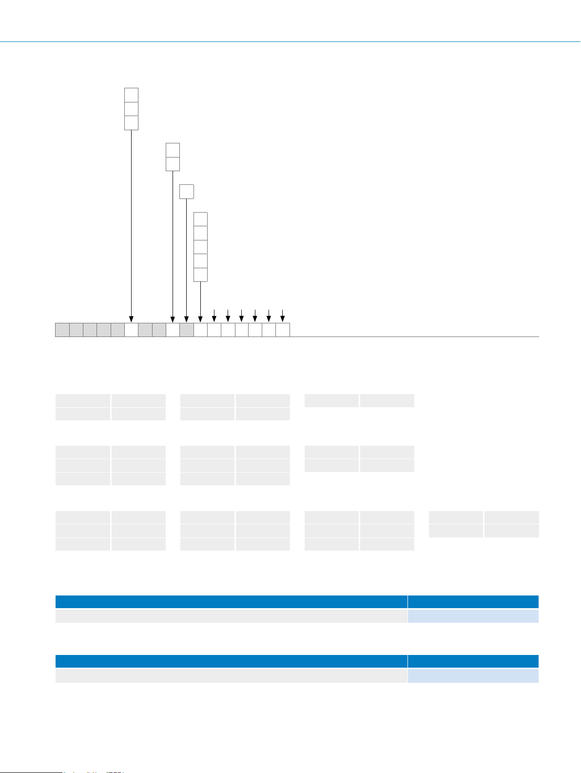
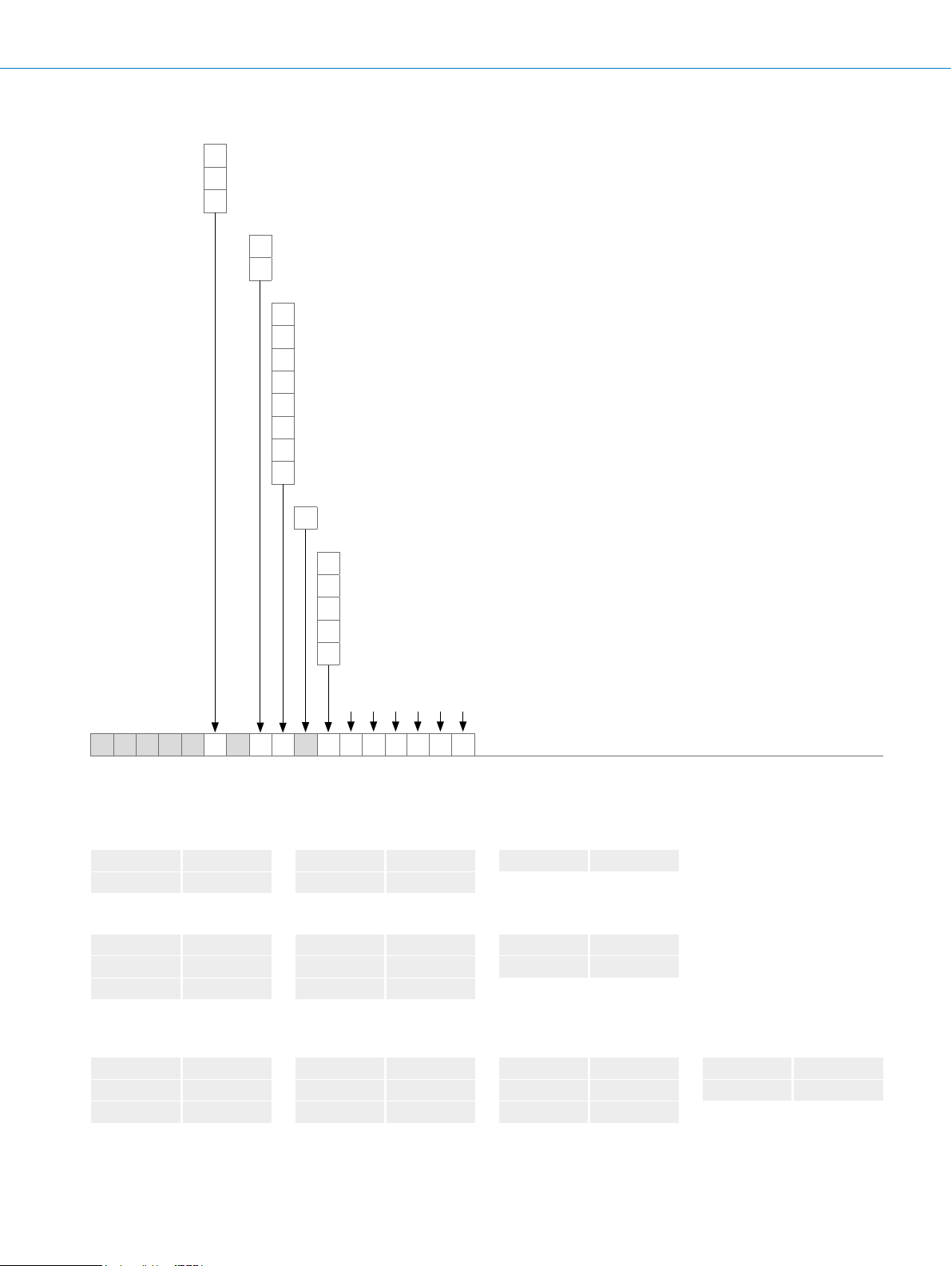
Singleturn SSI data format
t
12345678910 11 12 13 14 15 16 17 18 19 20 21
17 16 15 14 13 12 11 10 9 876543210
MSB
LSB
ERRDIG
ERRSI
Singleturn
ERRSYN
Bit 1–18: Position bits
• LSB: Least signicant bit
• MSB: Most signicant bit
Bit 19-21: Errorbits
• ERRDIG: Error message concerning speed. If this error occurs during the position forming process, it is displayed through the
ERRDIG bit.
• ERRSI: Light source error.
• ERRSYNC: Contamination of the code disk or read system. A error has occurred during the position detection process since the
last SSI data transmission. The errorbit is deleted during the next data transmission.
Evaluation of the error bits must be realized in the PLC.
The error bits output do not have to be used by the PLC.
Example
If the absolute value encoder is adjusted to a resolution of 13 bits, 16 bits are output: 13 databits and 3 errorbits.
If the errorbits cannot be evaluated in the PLC, the control unit must be set to an encoder resolution of 13 bits. The errorbits must
then be masked out at the control.
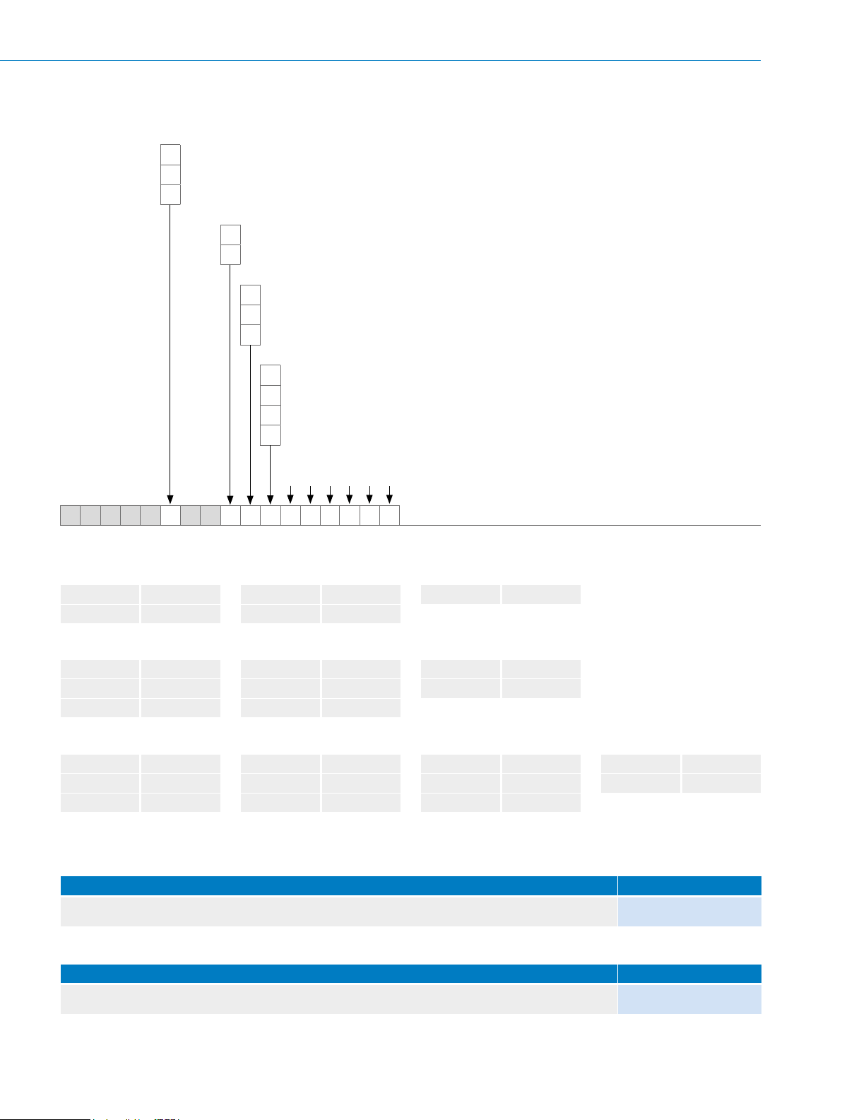
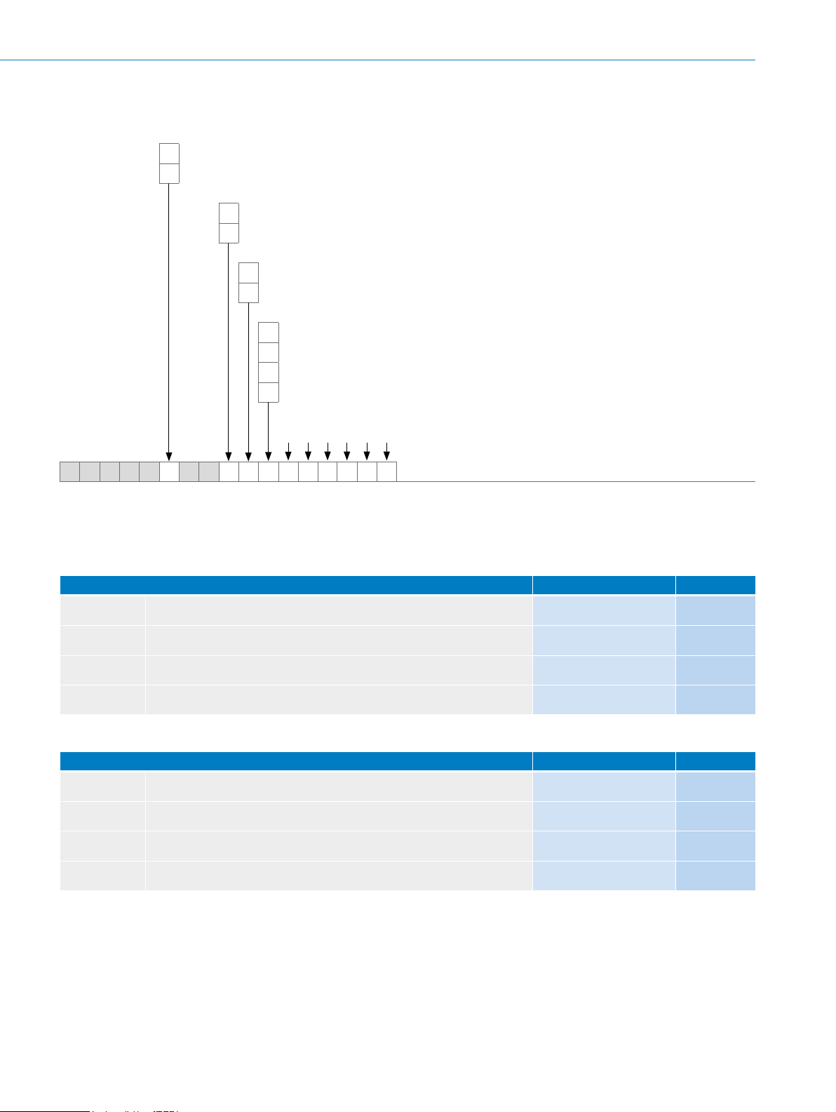
Multiturn SSI data format
30 bits
G
1
234567891011 12 13 14 15 16 17 18 19 20 21 22 23 24 25 26 27 2829 30 31 32 33
t
GGGGGGGGGGGGGGGGGGGGGGGGGGGGGG
+10A+11
AA+1A–1A–2A–3A–4A–5A–6A–7A–8A–9A
A+2A+3A+4A+5A+6A+7A+8A+9A
SingleturnMultiturn
–10A–11A–12A–13A–14A–15A–16A–17A–18
ERRDIG
ERRSI
ERRSYN
Bits 1–12: Multiturn position bits
Bits 13–30: Singleturn position bits
Bits 31–33: Errorbits
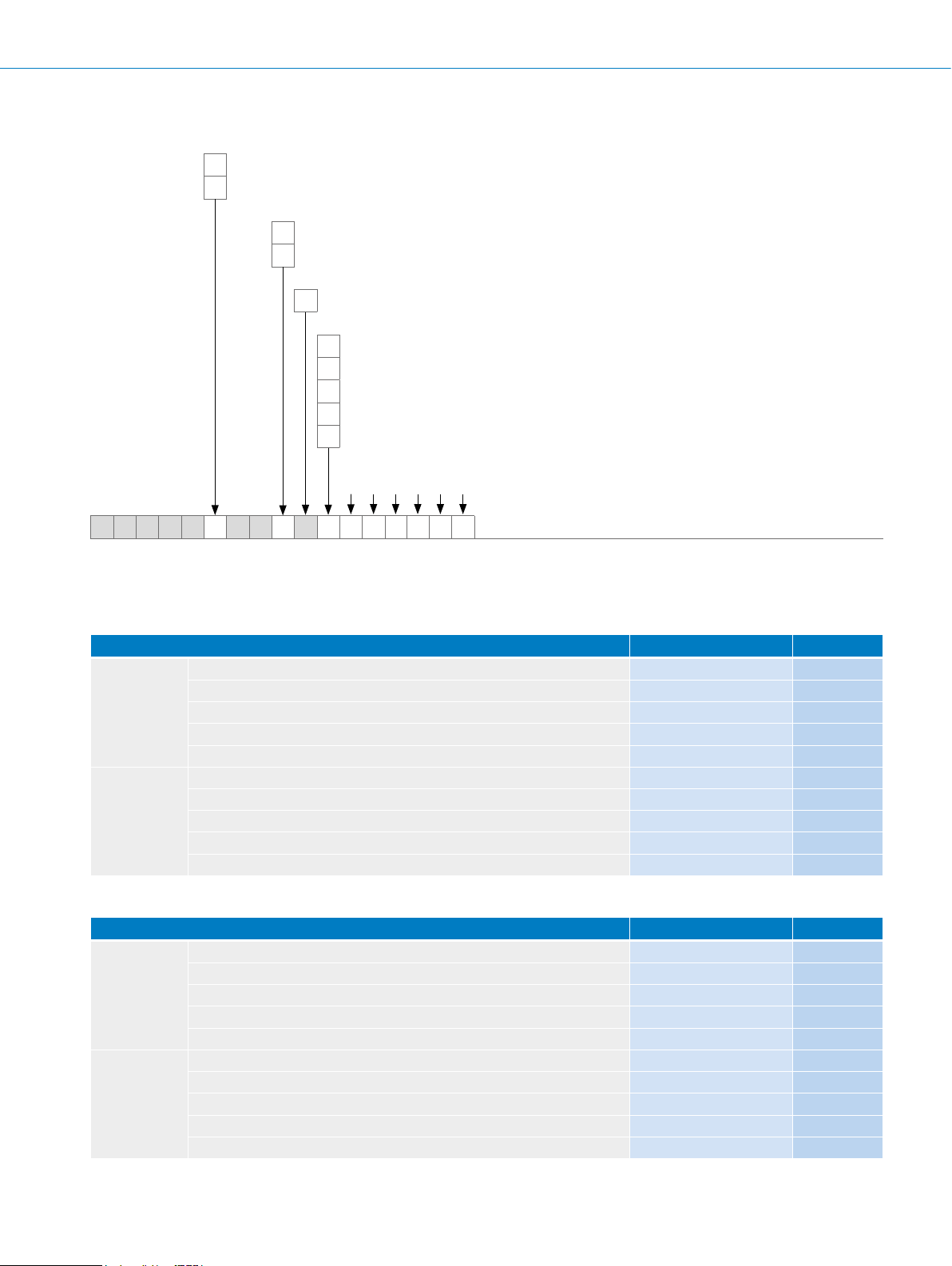
27 bits
1
234567891011 12 13 14 15 16 17 18 19 20 21 22 23 24 25 26 27 2829 30
t
GGGGGGGGGGGGGGGGGGGGGGGGGGG
+10A+11
AA+1A–1A–2A–3A–4A–5A–6A–7A–8A–9A
A+2A+3A+4A+5A+6A+7A+8A+9A
SingleturnMultiturn
–10A–11A–12A–13A–14A–15
ERRDIG
ERRSI
ERRSYN
Bit 1–12: Multiturn position bits
Bits 13–27: Singleturn position bits
Bits 28–30: Errorbits
Errorbits
• ERRDIG: Error message concerning speed. If this error occurs during the position forming process, it is displayed through the
ERRDIG bit.
• ERRSI: Light source error.
• ERRSYNC: Contamination of the code disk or read system. A error has occurred during the position detection process since the
last SSI data transmission. The errorbit is deleted during the next data transmission.
Evaluation of the error bits must be realized in the PLC.
The error bits output do not have to be used by the PLC. The multiturn resolution is xed to 12 bits.
Example
If the absolute value encoder is adjusted to a resolution of 27 bits, 30 bits are output: 27 databits and 3 errorbits.
If the errorbits cannot be evaluated in the PLC, the control unit must be set to an encoder resolution of 27 bits. The errorbits must
then be masked out at the control.
G-304
ENCODERS | SICK 8015560/2015-09-01
Subject to change without notice
Page 38

Interfaces
2.5
2.5
V
360° el.
COS+ ... COS–
SIN+ ... SIN–
V
V
360° el.
A
¯A
B
¯B
90° el.
ABSOLUTE ENCODERS AFS/AFM60 SSI
Electrical interfaces sin/cos 1.0 V
SS
Supply voltage Output
4.5 ... 32 V Sine 0.5 V
SS
Signals before difference at 120 Ω load
Signal diagram for clockwise shaft rotation, looking in direction “A” (shaft)
V
90° el.
V
COS+ COS–
SIN+ SIN–
Interface signals Sin, Sin, Cos, Cos Signals before difference at 120 Ω load Signal offset
Differential analog 0.5 V
0.5 V
0.5
± 20% 2.5 V ± 10%
SS
Signal after difference at 120 Ω load
Signal diagram for clockwise shaft rotation, looking in direction “A” (shaft)
0 V
90° el.
0 V
1
1
Incremental signal outputs for clockwise shaft rotation, looking in direction “A” (see dimensional drawing)
360° el.
Measuring step
G
Subject to change without notice
ENCODERS | SICK8015560/2015-09-01
G-305
Page 39

AFS/AFM60 SSI ABSOLUTE ENCODERS
Recommended accessories
Mounting systems
Mounting brackets and plates
Mounting bracket
Figure Brief description Type Part no.
G
Mounting bracket for encoder with centering hub 36 mm, including mounting kit for face
mount ange
Dimensional drawings g page K-725
BEF-WF-36 2029164
Flanges
Flange plate
Figure Brief description Type Part no.
Standard stator coupling BEF-DS00XFX 2056812
Stator coupling, 16.5 mm high BEF-DS05XFX 2057423
Stator coupling with hole circle diameter 63 mm BEF-DS07XFX 2059368
Flange adapter, adaptation of face mount ange with 36 mm centering hub to 50 mm
servo ange, aluminum, including 3 at head screws M4 x 10
Flange adapter, adaptation of face mount ange with 36 mm centering hub to 60 mm
square mounting plate, aluminum, including 3 at head screws M4 x 10
Flange adapter, adaptation of face mount ange with 36 mm centering hub to 58 mm
square mounting plate with shock absorbers, aluminum
BEF-FA-036-050 2029160
BEF-FA-036-060REC 2029162
BEF-FA-036-060RSA 2029163
Flange adapter, adaptation of face mount ange with 36 mm centering hub to 63 mm
square mounting plate, aluminum, including 3 at head screws M4 x 10
Flange adapter, adaptation of face mount ange with 36 mm centering hub to 100 mm
servo ange with 60 mm centering hub, aluminum
Dimensional drawings g page K-725
BEF-FA-036-063REC 2034225
BEF-FA-036-100 2029161
Other mounting accessories
Measuring wheels and measuring wheel systems
Figure Brief description Type Part no.
G-306
Measuring wheel with smooth plastic surface (Hytrel) for 10 mm solid shaft, circumference 200 mm
Measuring wheel with ridged plastic surface (Hytrel) for 10 mm solid shaft, circumference 200 mm
Measuring wheel with smooth plastic surface (Hytrel) for 10 mm solid shaft, circumference 500 mm
ENCODERS | SICK 8015560/2015-09-01
BEF-MR-010020 5312988
BEF-MR-010020G 5318678
BEF-MR-010050 5312989
Subject to change without notice
Page 40

ABSOLUTE ENCODERS AFS/AFM60 SSI
Figure Brief description Type Part no.
Measuring wheel with O-ring (NBR70) for 6 mm solid shaft, circumference 200 mm BEF-MR006020R 2055222
Measuring wheel with O-ring (NBR70) for 6 mm solid shaft, circumference 300 mm BEF-MR006030R 2055634
Measuring wheel with O-ring (NBR70) for 6 mm solid shaft, circumference 500 mm BEF-MR006050R 2055225
Measuring wheel with O-ring (NBR70) for 10 mm solid shaft, circumference 200 mm BEF-MR010020R 2055224
Measuring wheel with O-ring (NBR70) for 10 mm solid shaft, circumference 300 mm BEF-MR010030R 2049278
Measuring wheel with O-ring (NBR70) for 10 mm solid shaft, circumference 500 mm BEF-MR010050R 2055227
O-ring for measuring wheels (circumference 200 mm) BEF-OR-053-040 2064061
O-ring for measuring wheels (circumference 300 mm) BEF-OR-083-050 2064076
Dimensional drawings g page K-725
Modular measuring wheel system
Brief description Type Part no.
Measuring wheel system, desired mounting position: left, for DBS60-S4, DFS60-S4, AFS60-S4, and
AFM60-S4
Measuring wheel system, desired mounting position: right, for DBS60-S4, DFS60-S4, AFS60-S4, and
AFM60-S4
Dimensional drawings g page K-725
BEF-MRS-10-1 2071958
BEF-MRS-10-2 2071957
Mounting bell
Figure Brief description Type Part no.
Mounting bell for encoders with a servo ange, centering hub 50 mm, including mounting kit
Dimensional drawings g page K-725
BEF-MG-50 5312987
Servo clamps
Figure Brief description Type Part no.
Half-shell servo clamps (2 pcs.) for servo anges with a 50 mm centering hub BEF-WG-SF050 2029165
Servo clamps, large, for servo anges (clamps, eccentric fastener), 3 pcs., without
mounting material
Dimensional drawings g page K-725
BEF-WK-SF 2029166
Miscellaneous
Figure Brief description Type Part no.
Mounting kit for servo ange encoder on the bearing block, 1 bar coupling SKPS
1520 06/06 1 hexagon socket wrench SW1.5 DIN 911, 3 mounting eccentric BEMN
1242 49 3 screws M4 x 10 DIN 912, 1 hexagon socket wrench SW3 DIN 911
BEF-MK-LB 5320872
G
Bearing block for hollow shaft encoder, including xing screws BEF-FA-B12-010 2042728
Bearing block for servo and face mount ange encoder BEF-FA-LB1210 2044591
Dimensional drawings g page K-725
Subject to change without notice
ENCODERS | SICK8015560/2015-09-01
G-307
Page 41

G
AFS/AFM60 SSI ABSOLUTE ENCODERS
Shaft adaptation
Shaft couplings
Figure Brief description Type Part no.
Bellows coupling, shaft diameter 6 mm / 6 mm, maximum shaft offset: radial
± 0.25 mm, axial ± 0.4 mm, angular ± 4°; max. speed 10,000 rpm, –30 °C ... +120 °C,
max. torque 80 Ncm; material: stainless steel bellows, aluminum hub
Bellows coupling, shaft diameter 6 mm / 10 mm, maximum shaft offset: radial
± 0.25 mm, axial ± 0.4 mm, angular ± 4°; max. speed 10,000 rpm, –30 °C ... +120 °C,
max. torque 80 Ncm; material: stainless steel bellows, aluminum hub
Bellows coupling, shaft diameter 10 mm/10 mm; maximum shaft offset: radial
± 0.25 mm, axial ± 0.4 mm, angular ± 4°; max. revolutions 10,000 rpm,
–30° ... +120 °C, max. torque 80 Ncm; material: stainless steel bellows, aluminum
clamping hubs
Bellows coupling, shaft diameter 10 mm/12 mm; maximum shaft offset: radial
± 0.25 mm, axial ± 0.4 mm, angular ± 4°; max. revolutions 10,000 rpm,
–30 °C ... +120 °C, max. torque 80 Ncm; material: stainless steel bellows, aluminum
clamping hubs
Bar coupling, shaft diameter 6 mm / 6 mm, maximum shaft offset: radial ± 0.3 mm,
axial ± 0.2 mm, angle ± 3°; max. speed 10,000 rpm, –10 °C ... +80 °C, max. torque
80 Ncm; material: ber-glass reinforced polyamide, aluminum hub
Bar coupling, shaft diameter 6 mm / 8 mm, maximum shaft offset radial ± 0.3 mm, ax-
ial ± 0.2 mm, angle ± 3°; max. speed 10,000 rpm, torsion spring rigidity 38 Nm/wheel;
material: ber-glass reinforced polyamide, aluminum hub
Bar coupling, shaft diameter 6 mm/10 mm, maximum shaft offset: radial ± 0.3 mm,
axial ± 0.2 mm, angular ± 3°; max. speed 10,000 rpm, –10 °C ... +80 °C, max. torque
80 Ncm; material: ber-glass reinforced polyamide, aluminum hub
Bar coupling, shaft diameter 8 mm / 10 mm, maximum shaft offset: radial ± 0.3 mm,
axial ± 0.2 mm, angular ± 3°; torsion spring rigidity 38 Nm/wheel; material: ber-glass
reinforced polyamide, aluminum hub
Bar coupling, shaft diameter 10 mm / 10 mm, maximum shaft offset radial ± 0.3 mm,
axial ± 0.2 mm, angle ± 3°; max. speed 10,000 rpm, torsion spring rigidity 38 Nm/
wheel; material: ber-glass reinforced polyamide, aluminum hub
Double-loop coupling, shaft diameter 6 mm/10 mm, maximum shaft offset: radial
± 2.5 mm, axial ± 3 mm, angular ± 10°; max. speed 3,000 rpm, –30 °C ... +80 °C,
max. torque 1.5 Nm; material: polyurethane, galvanized steel ange
Double-loop coupling, shaft diameter 8 mm/10 mm, maximum shaft offset: radial
± 2.5 mm, axial ± 3 mm, angular ± 10°; max. speed 3,000 rpm, –30 °C ... +80 °C,
max. torque 1.5 Nm; material: polyurethane, galvanized steel ange
Double-loop coupling, shaft diameter 10 mm/10 mm, maximum shaft offset: radial
± 2.5 mm, axial ± 3 mm, angular ± 10°; max. speed 3,000 rpm, –30 °C ... +80 °C,
max. torque 1.5 Nm; material: polyurethane, galvanized steel ange
Double-loop coupling, shaft diameter 10 mm/12 mm, maximum shaft offset: radial
± 2.5 mm, axial ± 3 mm, angular ± 10°; max. speed 3,000 rpm, –30 °C ... +80 °C,
max. torque 1.5 Nm; material: polyurethane, galvanized steel ange
Spring washer coupling, shaft diameter 6 mm/10 mm, maximum shaft offset: radial
± 0.3 mm, axial ± 0.4 mm, angular ± 2.5°; max. speed 12,000 rpm, –10 °C ... +80 °C,
max. torque 60 Ncm; material: aluminum ange, ber-glass reinforced polyamide mem-
brane and tempered steel coupling pin
Spring washer coupling, shaft diameter 10 mm / 10 mm, maximum shaft offset: radial
± 0.3 mm, axial ± 0.4 mm, angular ± 2.5°; max. speed 12,000 rpm, –10° ... +80° C,
max. torque 60 Ncm; material: aluminum ange, glass ber-reinforced polyamide mem-
brane and hardened steel coupling pin
KUP-0606-B 5312981
KUP-0610-B 5312982
KUP-1010-B 5312983
KUP-1012-B 5312984
KUP-0606-S 2056406
KUP-0608-S 5314179
KUP-0610-S 2056407
KUP-0810-S 5314178
KUP-1010-S 2056408
KUP-0610-D 5326697
KUP-0810-D 5326704
KUP-1010-D 5326703
KUP-1012-D 5326702
KUP-0610-F 5312985
KUP-1010-F 5312986
Dimensional drawings g page K-725
G-308
ENCODERS | SICK 8015560/2015-09-01
Subject to change without notice
Page 42

Connectivity
Plug connectors and cables
Connecting cables with female connector
ABSOLUTE ENCODERS AFS/AFM60 SSI
Figure Brief description Length
Head A: female connector, M12, 8-pin, straight
Head B: cable
Cable: suitable for drag chain, PVC, shielded, 4 x 2 x 0.25 mm², Ø 7.0 mm
Head A: female connector, JST, 8-pin, straight
Head B: cable
Cable: suitable for drag chain, PUR, halogen-free, shielded, 4 x 2 x 0.15 mm²,
Ø 5.6 mm
Head A: female connector, M23, 12-pin, straight
Head B: cable
Cable: suitable for drag chain, PUR, halogen-free, shielded, 4 x 2 x 0.15 mm²,
Ø 5.6 mm
Head A: female connector, M23, 12-pin, straight
Head B: cable
Cable: suitable for drag chain, PUR, shielded, 4 x 2 x 0.25 mm² + 2 x 0.5 mm²
+ 1 x 0.14 mm², Ø 7.8 mm
1)
Suitable for SSI interfaces, not suitable for SSI + Incremental or SSI + Sin/Cos interfaces.
2)
Suitable for SSI + Incremental and SSI + Sin/Cos interfaces.
Dimensional drawings g page K-725
1)
2)
Type Part no.
of
cable
2 m DOL-1208-G02MAC1 6032866
5 m DOL-1208-G05MAC1 6032867
10 m DOL-1208-G10MAC1 6032868
20 m DOL-1208-G20MAC1 6032869
0.5 m DOL-0J08-G0M5AA6 2048589
1.5 m DOL-0J08-G1M5AA6 2048590
3 m DOL-0J08-G3M0AA6 2048591
5 m DOL-0J08-G5M0AA6 2048593
10 m DOL-0J08-G10MAA6 2048594
0.5 m DOL-2308-G0M5AA6 2048595
1.5 m DOL-2308-G1M5AA6 2048596
3 m DOL-2308-G03MAA6 2048597
5 m DOL-2308-G05MAA6 2048598
10 m DOL-2308-G10MAA6 2048599
1.5 m DOL-2312-G1M5MD2 2062284
3 m DOL-2312-G03MMD2 2062300
5 m DOL-2312-G05MMD2 2062301
10 m DOL-2312-G10MMD2 2062302
20 m DOL-2312-G20MMD2 2062303
30 m DOL-2312-G30MMD2 2062304
G
Subject to change without notice
ENCODERS | SICK8015560/2015-09-01
G-309
Page 43

AFS/AFM60 SSI ABSOLUTE ENCODERS
Female connectors (ready to assemble)
Figure Brief description Type Part no.
Head A: female connector, M12, 8-pin, straight, A encoded, shielded, for cable diameter
4 mm ... 8 mm
Head B: -
Operating temperature: –40 °C ... +85 °C
Head A: female connector, M23, 12-pin, straight, shielded, for cable diameter
5.5 mm ... 10.5 mm
Head B: -
Operating temperature: –20 °C ... +130 °C
Head A: female connector, M23, 12-pin, straight, shielded, for cable diameter
5.5 mm ... 10.5 mm
Head B: Operating temperature:
–40 °C ... +125 °C
Head A: female connector, M23, 12-pin, angled, shielded, for cable diameter
4.2 mm ... 6.6 mm
Head B: -
Operating temperature: –20 °C ... +130 °C
Head A: female connector, M23, 21-pin, straight, shielded, for cable diameter
5.5 mm ... 12 mm
Head B: -
Dimensional drawings g page K-725
DOS-1208-GA01 6045001
DOS-2312-G 6027538
DOS-2312-G02
DOS-2312-W01 2072580
DOS-2321-G 6027539
2077057
G
Cables (ready to assemble)
Figure Brief description Length
Type Part no.
of
cable
Head A: cable
Head B: cable
Cable: suitable for drag chain, PUR, halogen-free, shielded, 4 x 2 x 0.15 mm²,
Ø 5.6 mm
Head A: cable
Head B: cable
Cable: suitable for drag chain, PUR, halogen-free, shielded, UV and saltwater-resistant, 4 x 2 x 0.25 mm² + 2 x 0.5 mm² + 2 x 0.14 mm², Ø 7.8 mm
Dimensional drawings g page K-725
By the
meter
By the
meter
LTG-2308-MWENC 6027529
LTG-2612-MW 6028516
Male connectors (ready to assemble)
Figure Brief description Type Part no.
Head A: male connector, M12, 8-pin, straight, A encoded, shielded, for cable diameter
4 mm ... 8 mm
Head B: -
Operating temperature: –40 °C ... +85 °C
Head A: male connector, M23, 12-pin, straight, shielded, for cable diameter
5.5 mm ... 10.5 mm
Head B: -
Operating temperature: –20 °C ... +130 °C
Dimensional drawings g page K-725
STE-1208-GA01 6044892
STE-2312-G 6027537
G-310
ENCODERS | SICK 8015560/2015-09-01
Subject to change without notice
Page 44

Connection cables with female and male connector
ABSOLUTE ENCODERS AFS/AFM60 SSI
Figure Brief description Length
Type Part no.
of
cable
Head A: female connector, M12, 8-pin, straight
Head B: male connector, D-Sub, 9-pin, straight
Cable: PUR, halogen-free, shielded, 4 x 2 x 0.15 mm²
Head A: female connector, M23, 12-pin, straight
Head B: male connector, D-Sub, 9-pin, straight
Cable: suitable for drag chain, PUR, halogen-free, shielded, 4 x 2 x 0.15 mm²
Head A: female connector, M23, 12-pin, straight
1)
Suitable for use with SSI interfaces, not suitable for use with SSI + Incremental interface or SSI + Sin/Cos.
2)
Suitable for use with SSI + Incremental or SSI + Sin/Cos interfaces.
Dimensional drawings g page K-725
Head B: male connector, D-Sub, 9-pin, straight, 8-wire
2)
0.5 m DSL-2D08-G0M5AC2 2048439
0.5 m DSL-3D08-G0M5AC2 2048440
1)
0.5 m DSL-3D08-G0M5AC4 2059270
Other accessories
Programming and conguration tools
Figure Brief description Type Part no.
Programming unit USB, for programmable SICK encoders AFS60, AFM60, DFS60,
VFS60, DFV60 and wire draw encoders with programmable encoder.
Programming unit display for programmable SICK DFS60, DFV60, AFS/AFM60, AHS/
AHM36 encoders, and wire draw encoders with DFS60, AFS/AFM60, and AHS/AHM36.
Compact dimensions, low weight, and intuitive operation.
PGT-08-S 1036616
PGT-10-Pro 1072254
Dimensional drawings g page K-725
- For additional accessories, please see page K-668 onwards
G
Subject to change without notice
ENCODERS | SICK8015560/2015-09-01
G-311
 Loading...