

WF-M668-UWP1
Wireless Module&Bluetooth Module
Features:
¾ Reserving System
IEEE Std. 802.11b
IEEE Std. 802.11g
IEEE Std. 802.11n
IEEE Std. 802.11a
IEEE Std. 802.11ac
Bluetooth 2.1+EDR,4.2 LE,5.0
¾ Chip Solution
MT7668AUN
¾ Band
2.4G+5 G
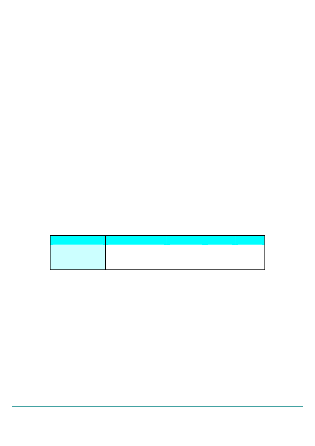
Model Standard Rate Channel POWER
IEEE 802.11a/b/g/n/ac 866.7Mbps 2.4G/5G
WF-M668-UWP1
Bluetooth 5.0 3Mbps 2.4G
Sichuan AI-Link Technology Co.,Ltd
Add:
Fax :
http://www.changhong.com
Anzhou, Industrial park, Mianyang, Sichuan, China
+86-0816-2416943
5V
Sichuan AI-Link Technology Co., Ltd.
1 of 17
page
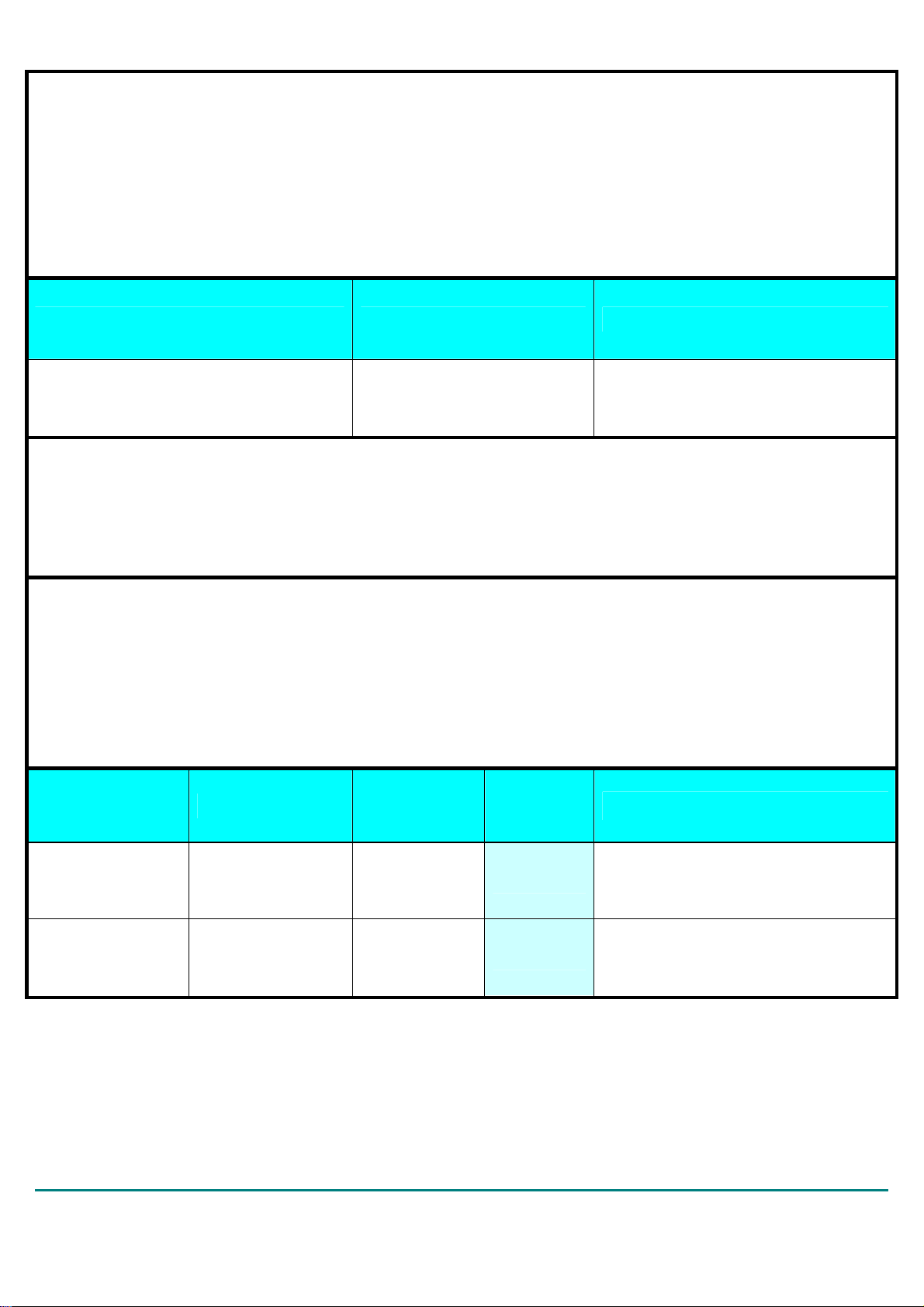
Feedback of customer’s Confirmation
We accept the specification after Confirmed
Customer name Customer signature Confirmation Date
Please feed back this paper and first paper after your signature by the address,thanks!
ADD: Anzhou,Industrial park,Mianyang,Sichuan,China
Factory: Sichuan AI-Link Technology Co.,Ltd.
Approved Checked
Product
Designed
WIFI Module
WF-M668-UWP1
Date
2017-11-10
Record of Modification
Sichuan AI-Link Technology Co., Ltd.
2 of 17
page

No
A
Date of
modification
2017-11-10
Main content of
modification
Confirmed for the first
time
Reason of
modification
Fan xijun
Serial number
of modification
Confirm
Sichuan AI-Link Technology Co., Ltd.
3 of 17
page
1. Introduction
WF-M668-UWP1 is based on MT7668AUN,complied with IEEE 802.11ab/g/n/ac dual-band WIFI
subsystem and a Bluetooth subsystem..
1.1 RF module Overview
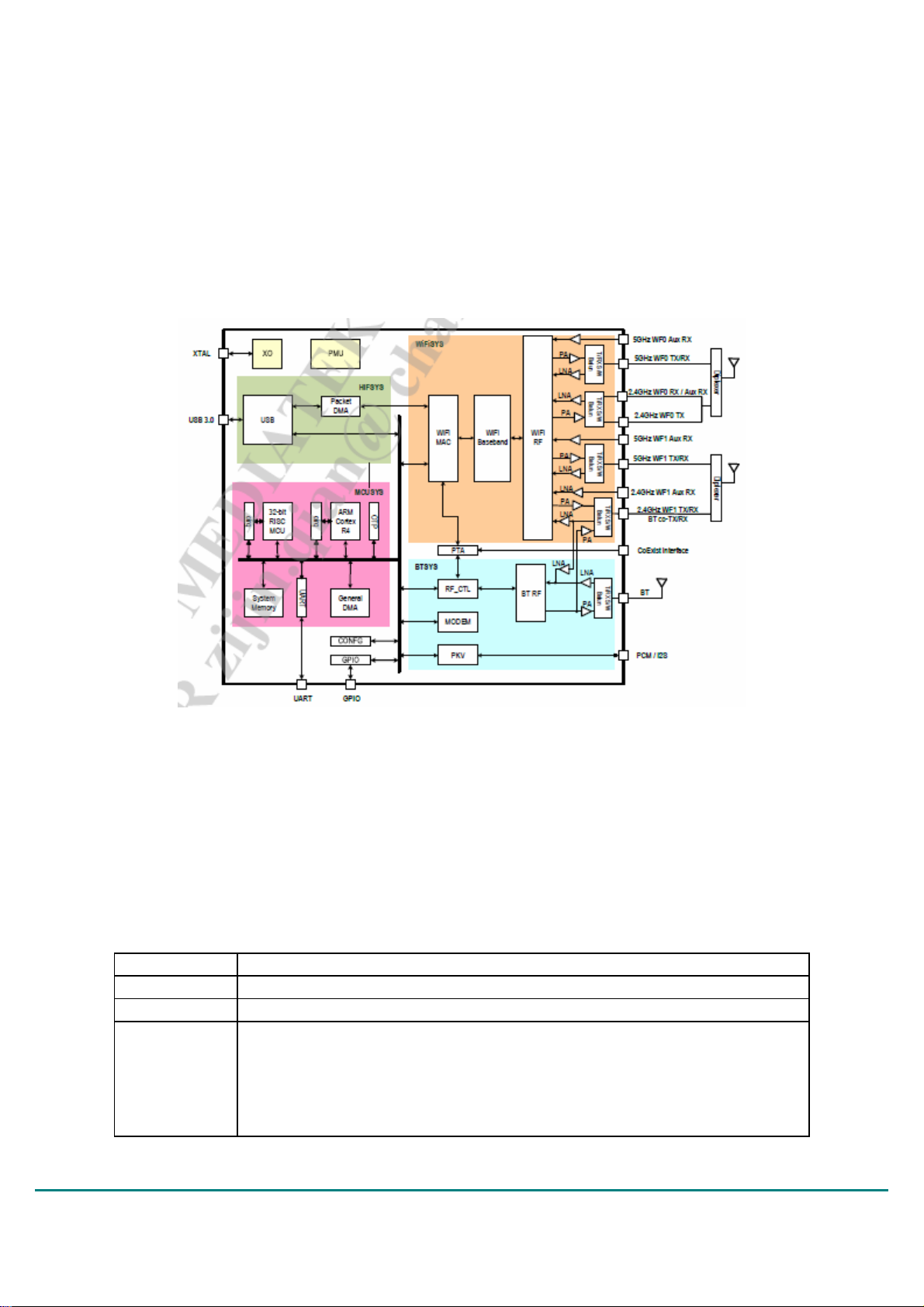
The general HW architecture for the module is shown in Figure 1. This WLAN Module design is based
on MTK MT7668AUN. It is a highly integrated single-chip MIMO(Multiple In Multiple Out) Wireless LAN
(WLAN) USB2.0 network interface controllercomplying with the 802.11n specification. It combines a
MAC, a 2T2R capable baseband,and RF in a single chip. The MT7668 provides a complete solution for
a highthroughput performance wireless client.The Bluetooth subsystem contains the Bluetooth
radio,baseband,link controller.It also uses the 32-bit RISC MCU for the Bluetooth protocols.
Figure 1 WF-M668-UWP1 Block Diagram
1.2 Specification reference
This specification is based on additional references listed below.
_ IEEE Std. 802.11b
_ IEEE Std. 802.11g
_ IEEE Std. 802.11n
_ IEEE Std. 802.11a
_ IEEE Std. 802.11ac
1.3 System Functions
Table1: General Specification as below:
Standard
Interface
ANT
Modulation
IEEE 802.11 b/a/ac/g/n Bluetooth 2.1+EDR,4.2 LE,5.0
USB 2.0
2T2R
802.11b:DBPSK,DQPSK,CCK for DSSS
802.11a/g:BPSK,QPSK,16QAM,64QAM for OFDM
802.11n:BPSK,QPSK,16QAM,64QAM for OFDM
802.11ac:BPSK, QPSK, 16QAM, 64QAM ,256QAM for OFDM
BT:
FHSS/GFSK/DQPSK/8DPSK
Sichuan AI-Link Technology Co., Ltd.
4 of 17
page
Operating
Frequency
TX Power
Frequency
offset
EVM
RX
Sensitivity
Channel
Operation
Voltage
2.400 ~ 2.4835 GHz,5.150~5.350 GHz,5.470~5.725 GHz,5.725~5.850 GHz
WiFi:
11b: 17 +/- 1.5dBm (11Mbps)
11g: 15 +/- 1.5dBm (54Mbps)
11a: 15 +/- 1.5dBm (54Mbps)
11n: 15 +/- 1.5dBm (MCS7 HT20)
11n: 15 +/- 1.5dBm (MCS7 HT40)
11ac: 13 +/- 1.5dBm (MCS9 HT20)
11ac: 13 +/- 1.5dBm (MCS9 HT40)
11ac: 13 +/- 1.5dBm (MCS9 HT80)
BT:
DH5,Class 1(5dBm Typical)
≤+-15PPM
11b @ 11Mbps: (Max.) : 35%, (Typical) : 6%
11a/g @ 54Mbps: (Max.) : -25dB , (Typical) : -30dB
11n @ MCS7 (2.4G/5.8GHT20): (Max.) : -28dB, (Typical) : -32dB
11n @ MCS7 (2.4G/5.8G HT40): (Max.) : -28dB, (Typical) : -32dB
11n @ MCS7 (ac HT20): (Max.) : -28dB, (Typical) : -32dB
11n @ MCS7 (ac HT40): (Max.) : -28dB, (Typical) : -32dB
11n @ MCS7 (ac HT80): (Max.) : -28dB, (Typical) : -32dB
WiFi:
11b @ 11Mbps: (Max.): -85dBm, (Typical): -86dBm (PER<8%)
11g @ 54Mbps: (Max.): -65dBm, (Typical): -73dBm (PER<10%)
11n @ MCS7 (2.4G/5.8G HT20): (Max.): -64dBm, (Typical): -71dBm
(PER<10%)
11n @ MCS7 (2.4G/5.8G HT40): (Max.): -61dBm, (Typical): -68dBm
(PER<10%)
11ac@ MCS9(HT20): (Max.): -57dBm, (Typical): -67dBm (PER<10%)
11ac@ MCS9(HT40): (Max.): -54dBm, (Typical): -63dBm (PER<10%)
11ac@ MCS9(HT80): (Max.): -51dBm, (Typical): -58dBm (PER<10%)
BT:
GFSK: typical -93dBm
π/4 DQPSK: typical -93dBm
8DPSK: typical -87dBm
-97 dBm(BLE)
2.4GHz:CH1-CH13
5.8GHz:CH36-CH165
5V+/-5%
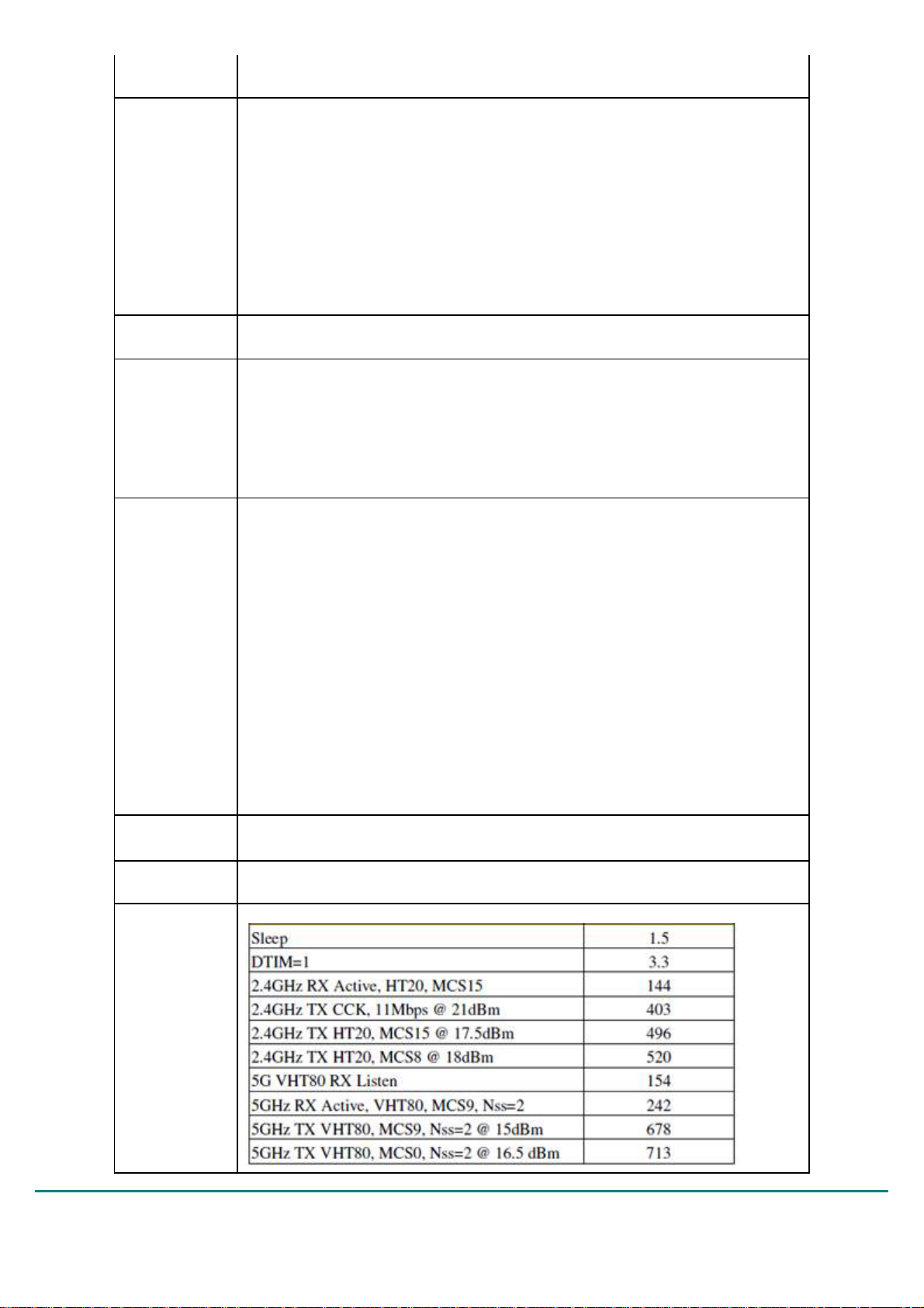
WIFI
Power
consumption
Sichuan AI-Link Technology Co., Ltd.
5 of 17
page
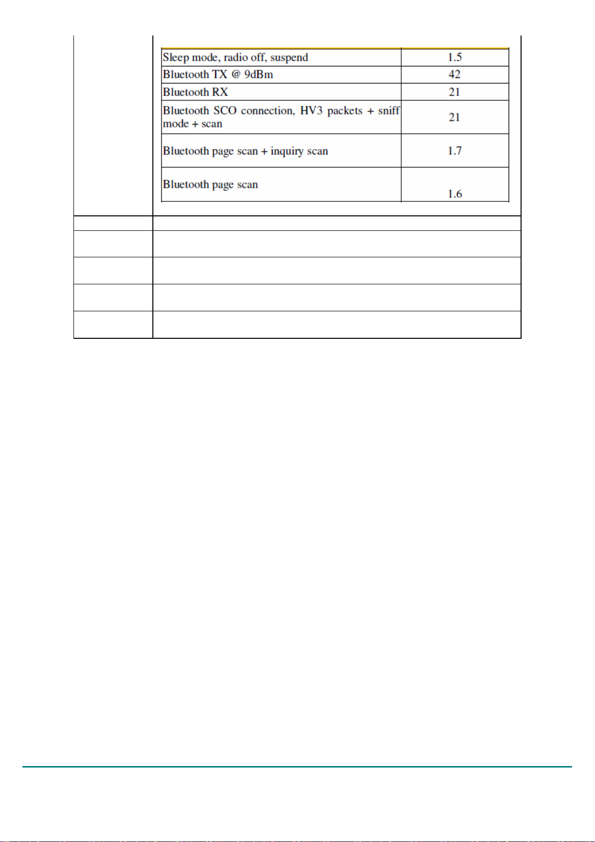
BT
ANT BT gain 1dBi,2.4G/5G WIFIgain 2dbi
Operation
Temperature
Storage
Temperature
Hardware
version
Software
version
-10℃ to +70℃
-40℃ to +125℃
JUB7.820.0243-1
customer_package_UIv1.84_DLLv3.84_20170627_WinDriverV.0.0.4.
26_FWv.66103 above.
Sichuan AI-Link Technology Co., Ltd.
6 of 17
page

2. Mechanical Specification
Typical Dimension (W x L x T): 70mmx 33mm x6.0mm (tolerance : +/-0.2 mm)
PCB Thickness: 1.0mm
Sichuan AI-Link Technology Co., Ltd.
7 of 17
page

NO Defintion
N
N
1 DC_EN Control the DC/DC to reset the Module
2 NC
3 VCC Power supply
4 DN USB D-
5 DP USB D+
6、7
8 3D_SYNC 3D signal synchronization
9 REG_ON Reset
10 WLAN_DEV_WAKE WIFI wake host
GND Ground
3. Product Picture
10 1
OTE
o Connect
Top view
Bottom view
Noet: No marked size tolerance: ±0.2mm
4. Electrical Specification
Sichuan AI-Link Technology Co., Ltd.
8 of 17
page

This Specification is based-on conductive DVT testing result. The extreme condition include overall temperature (0
℃,+25℃,+60℃) .
4 1 IEEE 802.11g/a Section:
Items Contents
Specification
Mode BPSK, QPSK, 16QAM, 64QAM and OFDM
Channel
Data rate 6, 9, 12, 18, 24, 36, 48, 54Mbps
TX Characteristics Min. Typ. Max. Unit Remark
1. Power Levels
1) 15dBm Target (For Each antenna port) @ 11g 13 15 17 dBm
2) 14dBm Target (For Each antenna port) @ 11a 13 15 17 dBm
2. Spectrum Mask @ Target Power
1) at fc +/-11MHz - - -20 dBr
2) at fc +/-20MHz - - -28 dBr
3) at fc > +/-30MHz - - -40 dBr
3. Constellation Error(EVM) @ Target Power
1) 6Mbps - - -5 dB
2) 9Mbps - - -8 dB
3) 12Mbps - - -10 dB
4) 18Mbps - - -13 dB
5) 24Mbps - - -16 dB
6) 36Mbps - - -19 dB
7) 48Mbps - - -22 dB
8) 54Mbps - - -25 dB
4. Frequency Error
1) IEEE802.11g -10 - 10 ppm
2) IEEE802.11a -10 10 ppm
RX Characteristics Min. Typ. Max. Unit
5. Minimum Input Level Sensitivity(each chain)
1) 6Mbps (PER ≦10%)
2) 9Mbps (PER ≦10%)
3) 12Mbps (PER ≦10%)
4) 18Mbps (PER ≦10%)
5) 24Mbps (PER ≦10%)
6) 36Mbps (PER ≦10%)
7) 48Mbps (PER ≦10%)
8) 54Mbps (PER ≦10%)
6. Maximum Input Level (PER ≦10%)
1) IEEE802.11g -20 - - dBm
2) IEEE802.11a -30 dBm
- - -82 dBm
- - -81 dBm
- - -79 dBm
- - -77 dBm
- - -74 dBm
- - -70 dBm
- - -66 dBm
- - -65 dBm
IEEE802.11g
IEEE802.11a
CH1 to CH13 @ 11g
CH36 to CH165 @ 11a
4.2 IEEE 802.11b Section:
Items Contents
Sichuan AI-Link Technology Co., Ltd.
9 of 17
page

Specification IEEE802.11b
Mode DBPSK, DQPSK and CCK and DSSS
Channel CH1 to CH13
Data rate 1, 2, 5.5, 11Mbps
TX Characteristics Min. Typ. Max. Unit Remark
1. Power Levels(Calibrated)
1) 17dBm Target (For Each antenna port) 15 17 19 dBm
2. Spectrum Mask @ Target Power
1) fc +/-11MHz to +/-22MHz - - -30 dBr
2) fc > +/-22MHz - - -50 dBr
3. Constellation Error(EVM) @ Target Power
1) 1Mbps - - -10 dB
2) 2Mbps - - -10 dB
3) 5.5Mbps - - -10 dB
4) 11Mbps - -20 -10 dB
4. Frequency Error -10 - 10 ppm
RX Characteristics Min. Typ. Max. Unit
5. Minimum Input Level Sensitivity(each chain)
1) 1Mbps (FER ≦8%)
2) 2Mbps (FER ≦8%)
3) 5.5Mbps (FER ≦8%)
4) 11Mbps (FER ≦8%)
6. Maximum Input Level (FER ≦8%)
- -83 -76 dBm
- -80 -76 dBm
- -79 -76 dBm
- -76 -76 dBm
-10 - - dBm
4.3 IEEE 802.11n HT20 Section:
Items Contents
Specification IEEE802.11n HT20 @ 2.4G
Sichuan AI-Link Technology Co., Ltd.
10 of 17
page

IEEE802.11n HT20 @ 5G
Mode BPSK, QPSK, 16QAM, 64QAM and OFDM
Channel
Data rate (MCS index) MCS0/1/2/3/4/5/6/7/8/9/10/11/12/13/14/15
TX Characteristics Min. Typ. Max. Unit Remark
1. Power Levels
1) 14dBm Target (For Each antenna port) @ 2.4G 13 15 17 dBm
2) 13dBm Target (For Each antenna port) @ 5G 13 15 17 dBm
2. Spectrum Mask @ Target Power
1) at fc +/-11MHz - - -20 dBr
2) at fc +/-20MHz - - -28 dBr
3) at fc > +/-30MHz - - -45 dBr
3. Constellation Error(EVM) @ Target Power
1) MCS0 - - -5 dB
2) MCS1 - - -10 dB
3) MCS2 - - -13 dB
4) MCS3 - - -16 dB
5) MCS4 - - -19 dB
6) MCS5 - - -22 dB
7) MCS6 - - -25 dB
8) MCS7 - - -28 dB
4. Frequency Error
1) IEEE802.11n HT20 @ 2.4G -10 - 10 ppm
2) IEEE802.11n HT20 @ 5G -10 - 10 ppm
RX Characteristics Min. Typ. Max. Unit
5. Minimum Input Level Sensitivity(each chain)
1) MCS0 (PER ≦10%)
2) MCS1 (PER ≦10%)
3) MCS2 (PER ≦10%)
4) MCS3 (PER ≦10%)
5) MCS4 (PER ≦10%)
6) MCS5 (PER ≦10%)
7) MCS6 (PER ≦10%)
8) MCS7 (PER ≦10%)
6. Maximum Input Level (PER ≦10%)
1) IEEE802.11n HT20 @ 2.4G -20 - - dBm
2) IEEE802.11n HT20 @ 5G -30 - - dBm
- - -82 dBm
- - -79 dBm
- - -77 dBm
- - -74 dBm
- - -70 dBm
- - -66 dBm
- - -65 dBm
- - -64 dBm
CH1 to CH13 @ 2.4G
CH36 to CH165 @ 5G
Sichuan AI-Link Technology Co., Ltd.
11 of 17
page

4.4 IEEE 802.11n HT40 Section:
Items Contents
Specification
Mode BPSK, QPSK, 16QAM, 64QAM and OFDM
Channel
Data rate (MCS index) MCS0/1/2/3/4/5/6/7/8/9/10/11/12/13/14/15
TX Characteristics Min. Typ. Max. Unit Remark
1. Power Levels (Calibrated)
1) 14dBm Target (For Each antenna port) @ 2.4G 13 15 17 dBm
2) 13dBm Target (For Each antenna port) @ 5G 13 15 17 dBm
2. Spectrum Mask @ Target Power
1) at fc +/-21MHz - - -20 dBr
2) at fc +/-40MHz - - -28 dBr
3) at fc > +/-60MHz - - -45 dBr
3. Constellation Error(EVM) @ Target Power
1) MCS0 - - -5 dB
2) MCS1 - - -10 dB
3) MCS2 - - -13 dB
4) MCS3 - - -16 dB
5) MCS4 - - -19 dB
6) MCS5 - - -22 dB
7) MCS6 - - -25 dB
8) MCS7 - - -28 dB
4. Frequency Error
1) IEEE802.11n HT20 @ 2.4G -10 - 10 ppm
2) IEEE802.11n HT20 @ 5G -12 - 12 ppm
RX Characteristics Min. Typ. Max. Unit
5. Minimum Input Level Sensitivity(each chain)
1) MCS0 (PER ≦10%)
2) MCS1 (PER ≦10%)
3) MCS2 (PER ≦10%)
4) MCS3 (PER ≦10%)
5) MCS4 (PER ≦10%)
6) MCS5 (PER ≦10%)
7) MCS6 (PER ≦10%)
8) MCS7 (PER ≦10%)
6. Maximum Input Level(PER ≦10%)
1) IEEE802.11n HT20 @ 2.4G -20 - - dBm
2) IEEE802.11n HT20 @ 5G -30 - - dBm
- - -79 dBm
- - -76 dBm
- - -74 dBm
- - -71 dBm
- - -67 dBm
- - -63 dBm
- - -62 dBm
- - -61 dBm
IEEE802.11n HT20 @ 2.4G
IEEE802.11n HT20 @ 5G
CH3 to CH11 @ 2.4G
CH38 to CH163 @ 5G
Sichuan AI-Link Technology Co., Ltd.
12 of 17
page

4.5 IEEE 802.11ac Section:
Items Contents
Specification IEEE802.11ac
Mode BPSK, QPSK, 16QAM, 64QAM ,256QAM and OFDM
CH36 to CH165 VHT20
Channel
Data rate (MCS index) MCS0/1/2/3/4/5/6/7/8/9
TX Characteristics Min. Typ. Max. Unit
1. Power Levels (Calibrated)
1) 11dBm Target (For Each antenna port) 11 13 15 dBm
2. Spectrum Mask @ Target Power
1) at fc +/-11MHz /20MHz/30MHz - - -20 dBr
2) at fc +/-21MHz /40MHz/60MHz - - -28 dBr
3) at fc +/-41MHz /80MHz/120MHz - - -40 dBr
3. Constellation Error(EVM) @ Target Power
1) MCS0 - - -5 dB
2) MCS1 - - -10 dB
3) MCS2 - - -13 dB
4) MCS3 - - -16 dB
5) MCS4 - - -19 dB
6) MCS5 - - -22 dB
7) MCS6 - - -25 dB
8) MCS7 - - -27 dB
9) MCS8 -30 dB
10) MCS9 -32 dB
4. Frequency Error -10 - 10 ppm
RX Characteristics Min. Typ. Max. Unit
5. Minimum Input Level Sensitivity(each chain) VHT20
1) MCS0 (PER ≦10%)
2) MCS1 (PER ≦10%)
3) MCS2 (PER ≦10%)
4) MCS3 (PER ≦10%)
5) MCS4 (PER ≦10%)
6) MCS5 (PER ≦10%)
7) MCS6 (PER ≦10%)
8) MCS7 (PER ≦10%)
9) MCS8 (PER ≦10%)
10) MCS9 (PER ≦10%)
6. Maximum Input Level(PER ≦10%)
- - -82
- - -79
- - -77
- - -74
- - -70
- - -66
- - -65
- - -64
- - -59 -56 -53 dBm
- - -57 -54 -51 dBm
-30 - - dBm
CH38 to CH163 VHT40
CH42 to CH157 VHT80
VHT4
-79 -76
-76 -73
-74 -71
-71 -68
-67 -64
-63 -60
-62 -59
-61 -58
VHT80
0
Remar
k
dBm
dBm
dBm
dBm
dBm
dBm
dBm
dBm
Sichuan AI-Link Technology Co., Ltd.
13 of 17
page

4.6 Bluetooth Section:
Items Contents
Specification
Mode
Number of Channel 79 Channels
Frequency Band 2.402 GHz ~2.480GHz
Min. Typ. Max. Unit Remark
1. Output Power - 3 - dBm
2.Gain step 5 dB Class1
3. Receiver sensitivity (BER ≦0.1%)
4. Maximum usable signal (BER ≦0.1%)
5. C/I co-channel (BER<0.1%) - 4 11 dB
6. C/I 1MHz (BER<0.1%) - -14 0 dB
7. C/I 2MHz (BER<0.1%) - -42 -30 dB
8. C/I≥3MHz (BER<0.1%) - -49 -40 dB
9. C/I Image channel (BER<0.1%) - -25 -9 dB
10. C/I Image 1MHz (BER<0.1%) - -50 -20 dB
11. Inter-modulation - -13 - dB
12. Out-of-band blocking
1). 30MHz to 2000MHz -10 - - dBm
2). 2000MHz to 2399MHz -27 - - dBm
3). 2498MHz to 3000MHz -27 - - dBm
4). 3000MHz to 12.75GHz -10 - - dBm
13. Modulation characteristics
1). Δf1avg 140 157 175 KHz
2). Δf2max (For at least 99.9% of all Δf2max) 115 140 - KHz
3). Δf1avg /Δf2avg 0.8 0.98 - KHz
14. ICFT -75
15. Carrier frequency drift
1). One slot packet (DH1) -25
2). Two slot packet (DH3) -40
3). Five slot packet (DH5) -40
4). Max drift rate - 6 20 KHz/50us
16. TX output spectrum(20dB bandwidth) - 922 1000 KHz
17. In-Band spurious emission
1). ±2MHz offset - -45
2). ±3MHz offset - -48
3). >±3MHz offset - -48
- -93.5 -80 dBm
- -5 -
BT2.1/3.0/4.0/5.0
FHSS,GFSK,DPSK,DQPSK
±20
±15
±15
±15
+75 KHz
+25 KHz
+40 KHz
+40 KHz
-20
-40
-40
dBm
dBm
dBm
Sichuan AI-Link Technology Co., Ltd.
14 of 17
page

6、The connector
Sichuan AI-Link Technology Co., Ltd.
15 of 17
page

7、Statement:
A、CE Radiation Exposure Statement
Herby, Sichuan AI-Link Technology Co., Ltd. declares that this Wireless Module&Bluetooth Module,WF-M668-UWP1
is in compliance with the essential requirements and other relevant provisions of Directive 2014/53/EU.
Operation Temperature:Use the WF-M668-UWP1 in the environment with the temperature between -10℃ and 70℃
Operation Frequency range:2.400 ~ 2.4835 GHz,5.150~5.350 GHz,5.470~5.725 GHz,5.725~5.850 GHz
The above frequency can be used of Europe without restriction.
Max RF Output Power: 20dBm
Manufacturer:Sichuan AI-Link Technology Co., Ltd.
Address:Anzhou,Industrial park,Mianyang,Sichuan, China
Tel: +86- 0816-2438701
Fax: +86-0816-2416943
E-mail: caixia.hu@changhong.com
B、FCC Radiation Exposure Statement
Changes or modifications not expressly approved by the party responsible for compliance could void the user's
authority to operate the equipment.
This equipment has been tested and found to comply with the limits for a Class B digital device, pursuant to Part 15 of
the FCC Rules. These limits are designed to provide reasonable protection against harmful interference in a
residential installation. This equipment generates uses and can radiate radio frequency energy and, if not installed and
used in accordance with the
instructions, may cause harmful interference to radio communications. However, there is no guarantee that
interference will not occur in a particular installation. If this equipment does cause harmful interference to radio or
television reception, which can be determined by turning the equipment off and on, the user is encouraged to try to
correct the interference by one or more of the following measures:
-- Reorient or relocate the receiving antenna.
-- Increase the separation between the equipment and receiver.
-- Connect the equipment into an outlet on a circuit different from that to which the receiver is connected.
-- Consult the dealer or an experienced radio/TV technician for help
This device complies with part 15 of the FCC rules. Operation is subject to the following two conditions (1)this device
may not cause harmful interference, and (2) this device must accept any interference received, including interference
that may cause undesired operation.
FCC Radiation Exposure Statement
The modular can be installed or integrated in mobile or fix devices only. This modular be installed in any portable
device, for example, USB dongle like transmitters is forbidden. This modular complies with FCC RF radiation exposure
limits set forth for an uncontrolled environment. This transmitter must not be collocated or operating in conjunction with
antenna or transmitter. If the FCC identification number is not visible when the module is installed inside another
device, then the outside of the device into which the module is installed must also display label referring to the
enclosed module. This exterior label can use wording such as the following:” Contains Transmitter Module FCC ID:
2AOKI-WFM668UWP1 Or Contains FCC ID: 2AOKI-WFM668UWP1 when the module is installed inside another
device, the user manual of this device must contain below warning statements;1. This device complies with Part 15 of
the FCC Rules. Operation is subject to the following two conditions :(1) This device may not cause harmful
interference.(2) This device must accept any interference received, including interference that may undesired
operation.2. Changes or modifications not expressly approved by the party responsible for compliance could void the
user's authority to operate the equipment. The devices must be installed and used in strict accordance with the
manufacturer’s instructions as described in the user documentation that comes with the product. This device is
intended only for OEM integrators under the followingconditions:1) The antenna must be installed such that 20 cm is
maintained between the antenna and user.2) The transmitter module may not be co-located with any other transmitter
or antenna. Module Antenna Type: BT: Ceramic Antenna, Wifi: Integral Antenna, ANT Gain: BT: 1dBi, 2.4G Wifi: 1dBi,
5G Wifi: 2dBi.
Sichuan AI-Link Technology Co., Ltd.
16 of 17
page

C、IC Radiation Exposure Statement
This device complies with Industry Canada’s licence-exempt RSSs. Operation is subject to the following two
conditions:
(1) This device may not cause interference; and
(2) This device must accept any interference, including interference that may cause undesired operation of the
device.
The term “IC: “ before the certification/registration number only signifies that the Industry Canada technical
specifications were met. This product meets the applicable Industry Canada technical specifications.
Le présent appareil est conforme aux CNR d'Industrie Canada applicable aux appareils radio exempts de licence.
L'exploitation est autorisée aux deux conditions suivantes : (1) l'appareil ne doit pas produire de brouillage,
et (2) l'utilisateur de l'appareil doit accepter tout brouillage radioélectrique subi, même si le brouillage est susceptible
d'en compromettre le fonctionnement
Sichuan AI-Link Technology Co., Ltd.
17 of 17
page
 Loading...