

LTM3210
IEEE 802.11b/g/n 1T1R SDIO IOT Module
Reserving System
IEEE Std. 802.11b
IEEE Std. 802.11g
IEEE Std. 802.11n
Chip Solution
WIFI :Qualcomm QCA4010
Size
30.0mm*16.0mm*3.0mm
Module Name
Install
Standard
Data
Rate
Band
Antenna
Interface
Note
LTM3210
SMT
IEEE 802.11b/g/n
135Mbps
2.4 GHz
Stamp Hole
3.3V power
supply
AI-LINK
Features
:
Model Overview
:
Sichuan AI-Link Technology Co.,Ltd
Add:
Tel: 13881190925
Web: http://www.changhong.com
Anzhou,Industrial park,Mianyang,Sichuan
LTM3210
Feedback of customer’s Confirmation
We accept the specification after Confirmed
Customer name
Customer signature
Confirmation Date
Please feed back this paper and first paper after your signature by the address,thanks!
ADD: Anzhou,Industrial park,Mianyang,Sichuan
Factory: Sichuan AI-Link Technology Co.,Ltd.
Approved
Checked
Designed
Product
WiFi Module
Model
LTM3210
Date
2018-07-03
IEEE 802.11b/g/n 1T1R SDIO IOT Module
Sichuan AI-Link Technology Co., Ltd. page 2 of 17

IEEE 802.11b/g/n 1T1R SDIO IOT Module
No
Date of
modification
Main content of
modification
Reason of
modification
Serial number of
modification
Confirm
V1.0
20180703
Initial release
Fengjie
Record of Modification
LTM3210
Sichuan AI-Link Technology Co., Ltd. page 3 of 17
LTM3210
1. Brief description:
QCA4010 chip
An integrated Balun to save cost and size, minimize tuning and tolerance
A printed antenna
2MB SPI Flash memory and etc
2.
Module Interface
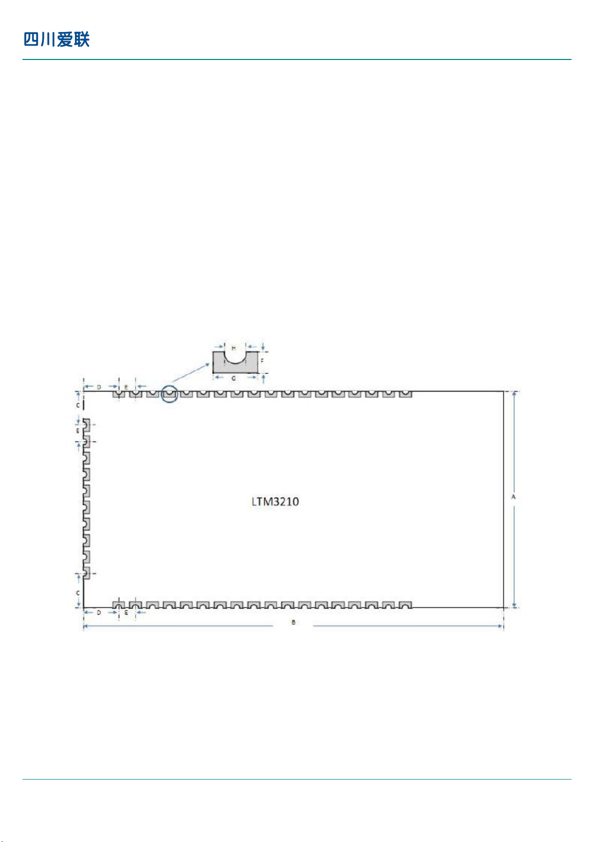
3. Package outline and Mounting:
IEEE 802.11b/g/n 1T1R SDIO IOT Module
IOT MODULE LTM3210 is based on Qualcomm QCA4010 complied with IEEE 802.11b/g/n standard in
2.4GHz ISM band.Supported for 135Mbps high speed wireless network connection.
LTM3210 module includes the following components:
LTM3210 manufacturing interface
USB 2.0 interface with integrated controller and PHY for manufacturing test and configuration.
LTM3210 host interfaces
UART host interface to a remote microcontroller with an AT style command set.
Figure 3.1 LTM3210 module dimensions
Sichuan AI-Link Technology Co., Ltd. page 4 of 17
IEEE 802.11b/g/n 1T1R SDIO IOT Module
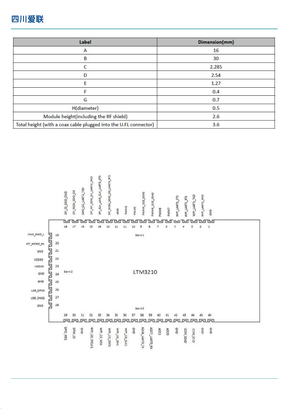
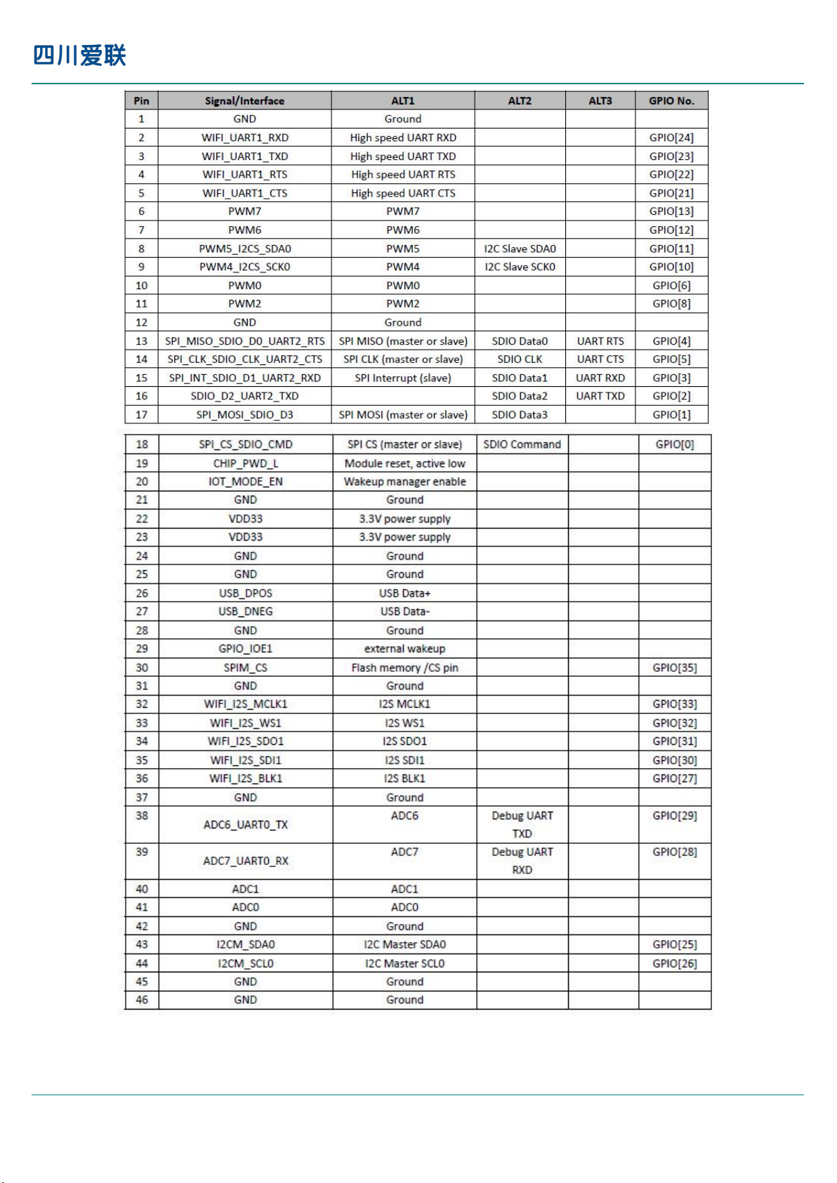
4. Pin Definition:
Table 3.1 LTM3210 module dimensions
NOTE: General tolerance ±0.2mm unless otherwise stated
LTM3210
Figure 4.1 top view
Sichuan AI-Link Technology Co., Ltd. page 5 of 17
LTM3210
IEEE 802.11b/g/n 1T1R SDIO IOT Module
Table 4.1 LTM3210 pin assignment
Sichuan AI-Link Technology Co., Ltd. page 6 of 17

5.Bootstrap Signals
6.Timing specifications
6.1 SPI master interface timing
LTM3210
IEEE 802.11b/g/n 1T1R SDIO IOT Module
Table 5.1 Bootstrap Signals
Figure 6.1 SPI master timing
Table 6.1 SPI master timing
Sichuan AI-Link Technology Co., Ltd. page 7 of 17

6.2 SPI slave interface timing
LTM3210
IEEE 802.11b/g/n 1T1R SDIO IOT Module
Figure 6.2 SPI slave timing
7.Product Pictures
Table 6.1 SPI slave timing
TOP VIEW BOTTOM VIEW
Sichuan AI-Link Technology Co., Ltd. page 8 of 17

8.Key Materials
Items
Category
MPN
Description
MFR
Notes
1
IC
QCA4010
116 QFN
Qualcomm
2
PCB
LTM3210
FR-4,2LAY
Sunlord
IQPCB
3
Crystal
E3SB40E000900E
40M
JWT
Hosonic
No.
Feature
Description
7-1
Operation Voltage
3.3V+/-0.3
7-2
Current Consumption
Total3.3V@Max 410mA
BW 40 MHZ@14dbm
7-3
Operation Temperature
0°C to +70°C
7-4
Antenna Type
Integral PCB antenna
7-5
SDIO
SDIO slave Interface
7-6
Storage Temperature
-45°C to +135°C
9.General Requirements:
LTM3210
IEEE 802.11b/g/n 1T1R SDIO IOT Module
Sichuan AI-Link Technology Co., Ltd. page 9 of 17

10.Electrical Characteristics:
10-1 IEEE 802.11b Section:
Items
Contents
Specification
IEEE802.11b
Mode
DSSS
Channel
CH1 to CH11
Data rate
1, 2, 5.5, 11Mbps
Min.
Typ.
Max.
Unit
Remark
TX Characteristics
1. Power Levels(Calibrated)
1) for each data rate
18.5
dBm
2. Spectrum Mask @ target power
1) fc +/-11MHz to +/-22MHz
---30
dBr
2) fc > +/-22MHz
---50
dBr
3 Constellation Error(EVM)@ target power
1) 1Mbps
---10
dB
2) 2Mbps
---10
dB
3) 5.5Mbps
---10
dB
4) 11Mbps
-
-10
dB
4. Frequency Error
-10-510
ppm
RX Characteristics
Min.
Typ.
Max.
Unit
5 Minimum Input Level Sensitivity(each chain)
1) 1Mbps (FER ≦8%)
-
-83
dBm
2) 2Mbps (FER ≦8%)
-
-80
dBm
3) 5.5Mbps (FER ≦8%)
-
-79
dBm
4) 11Mbps (FER ≦8%)
-
-76
dBm
6 Maximum Input Level (FER ≦8%)
-10--
dBm
LTM3210
IEEE 802.11b/g/n 1T1R SDIO IOT Module
Sichuan AI-Link Technology Co., Ltd. page 10 of 17

LTM3210
10-2 IEEE 802.11g Section:
Items
Contents
Specification
IEEE802.11g
Mode
OFDM
Channel
CH1 to CH11
Data rate
6, 9, 12, 18, 24, 36, 48, 54Mbps
Min.
Typ.
Max.
Unit
Remark
TX Characteristics
1. Power Levels
1) for each data rate
-
21.5
-
dBm
2. Spectrum Mask @ target power
1) at fc +/-11MHz
---20
dBr
2) at fc +/-20MHz
---28
dBr
3) at fc > +/-30MHz
---40
dBr
3 Constellation Error(EVM)@ target power
1) 6Mbps
---5
dB
2) 9Mbps
---8
dB
3) 12Mbps
---10
dB
4) 18Mbps
---13
dB
5) 24Mbps
---16
dB
6) 36Mbps
---19
dB
7) 48Mbps
---22
dB
8) 54Mbps
-
-25
dB
4 Frequency Error
-10-510
ppm
RX Characteristics
Min.
Typ.
Max.
Unit
5 Minimum Input Level Sensitivity(each chain)
1) 6Mbps (PER ≦10%)
-
-85
dBm
2) 9Mbps (PER ≦10%)
-
-84
dBm
3) 12Mbps (PER ≦10%)
-
-82
dBm
4) 18Mbps (PER ≦10%)
-
-80
dBm
5) 24Mbps (PER ≦10%)
-
-77
dBm
6) 36Mbps (PER ≦10%)
-
-73
dBm
7) 48Mbps (PER ≦10%)
-
-69
dBm
8) 54Mbps (PER ≦10%)
-
-65
dBm
6 Maximum Input Level (PER ≦10%)
-20--
dBm
IEEE 802.11b/g/n 1T1R SDIO IOT Module
Sichuan AI-Link Technology Co., Ltd. page 11 of 17

LTM3210
10-3 IEEE 802.11n HT20 Section:
Items
Contents
Specification
IEEE802.11n HT20 @ 2.4GHz ISM
Mode
OFDM
Channel
CH1 to CH11
Data rate (MCS index)
MCS0/1/2/3/4/5/6/7
Min.
Typ.
Max.
Unit
Remark
TX Characteristics
Min.
Typ.
Max.
Unit
2. Power Levels
1) for each data rate
-
19.5
-
dBm
3. Spectrum Mask @target power
1) at fc +/-11MHz
---20
dBr
2) at fc +/-20MHz
---28
dBr
3) at fc > +/-30MHz
---45
dBr
4. Constellation Error(EVM)@ target power
1) MCS0
---5
dB
2) MCS1
---10
dB
3) MCS2
---13
dB
4) MCS3
---16
dB
5) MCS4
---19
dB
6) MCS5
---22
dB
7) MCS6
---25
dB
8) MCS7
-
-28
dB
5. Frequency Error
-10-10
ppm
RX Characteristics
Min.
Typ.
Max.
Unit
6. Minimum Input Level Sensitivity(each chain)
1) MCS0 (PER ≦10%)
-
-82
dBm
2) MCS1 (PER ≦10%)
-
-79
dBm
3) MCS2 (PER ≦10%)
-
-77
dBm
4) MCS3 (PER ≦10%)
-
-74
dBm
5) MCS4 (PER ≦10%)
-
-70
dBm
6) MCS5 (PER ≦10%)
-
-66
dBm
7) MCS6 (PER ≦10%)
-
-65
dBm
8) MCS7 (PER ≦10%)
-
-64
dBm
7. Maximum Input Level (PER ≦10%)
-20--
dBm
IEEE 802.11b/g/n 1T1R SDIO IOT Module
Sichuan AI-Link Technology Co., Ltd. page 12 of 17

LTM3210
10-4 IEEE 802.11n HT40 Section:
Items
Contents
Specification
IEEE802.11n HT40 @ 2.4GHz ISM
Mode
OFDM
Channel
CH3 to CH9
Data rate (MCS index)
MCS0/1/2/3/4/5/6/7
Min.
Typ.
Max.
Unit
Remark
TX Characteristics
Min.
Typ.
Max.
Unit
1. Power Levels (Calibrated)
1) for each data rate
-
19.2
-
dBm
2. Spectrum Mask @target power
1) at fc +/-22MHz
---20
dBr
2) at fc +/-40MHz
---28
dBr
3) at fc > +/-60MHz
---45
dBr
3. Constellation Error(EVM)@target power
1) MCS0
---5
dB
2) MCS1
---10
dB
3) MCS2
---13
dB
4) MCS3
---16
dB
5) MCS4
---19
dB
6) MCS5
---22
dB
7) MCS6
---25
dB
8) MCS7
-
-28
dB
4. Frequency Error
-10-510
ppm
RX Characteristics
Min.
Typ.
Max.
Unit
5. Minimum Input Level Sensitivity(each chain)
1) MCS0 (PER ≦10%)
-79
dBm
2) MCS1 (PER ≦10%)
-76
dBm
3) MCS2 (PER ≦10%)
-74
dBm
4) MCS3 (PER ≦10%)
-71
dBm
5) MCS4 (PER ≦10%)
-67
dBm
6) MCS5 (PER ≦10%)
-63
dBm
7) MCS6 (PER ≦10%)
-62
dBm
8) MCS7 (PER ≦10%)
-
-61
dBm
6. Maximum Input Level(PER ≦10%)
-20--
dBm
IEEE 802.11b/g/n 1T1R SDIO IOT Module
Sichuan AI-Link Technology Co., Ltd. page 13 of 17

IEEE 802.11b/g/n 1T1R SDIO IOT Module
Test Items
Test Conditions
Qty
Criteria Condition
4-1
Drop test
The packed samples within
100Kg can be tested
Drop height:
Face Side: 800/600/450mm
Edge line: 600/450/350mm
Drop time: 1 each Face and
edge.
1xBox
After drop test, the outer box and inner box will
not been broken by appearance visual
inspection.
4-2
Vibration test
X-Y-Z direction, first
Frequency changing from
10Hz to 30Hz to 10Hz
,amplitude 0.75mm, 5 times
vibrations, then frequency
Changing from 30Hz to 55
Hz to 30 Hz, amplitude
0.15mm, 5 time vibration.
3
After test, the Appearance, Power EVM and
Frequency error shall be satisfied with the
specification.
4-3
Impact test
Impact acceleration:
50m/sec2;
Impact duration: 16ms;
Impact times: 1000.
3
After test, the Appearance, Power EVM and
Frequency error shall be satisfied with the
specification.
4-4
Soldering ability
test
Soldering temperature:
235±5℃
Soldering duration:
2±0.5S
3
1. After soldering, the soldered area must be
covered by a smooth bright solder layer, some
deficiencies such as a small amount of the
pinhole, not wetting are allowed, but the
deficiencies can not be in the same place;
2. At least 90% of soldered area shall be covered
continuously by the soldering material.
4-5
Humidity test
Leave samples in 40±3℃,
93% RH @ 96 hours
3
Leave samples in standard test condition for 2
hours then test, the Appearance, Power, EVM
and Frequency error functional parameter shall
be satisfied with the test specification.
4-6
High temperature
load life test
Thermostat cabinet
temperature: 55±5℃
Applied voltage:
110% rated voltage
Working duration: 200 hour
(Supply Voltage Cycle
23h power on, 1h power off)
60
After test, leave samples in standard condition
for 1 hour and test, Power, EVM and Frequency
error shall be satisfied with the test specification.
4-7
High temperature
load test
Temperature: 55±5℃
Samples work for 16 hours
3
After test, the Appearance, Power, EVM and
Frequency error shall be Satisfied with the test
specification.
4-8
Low temperature
storage test
Leave the samples in
-25±3℃@24 hours
3
Leave samples in standard test condition for 2
hours then test, the Appearance, Power, EVM
and Frequency error shall be satisfied with the
test specification.
11.Mechanical, Environmental and Reliability Tests
LTM3210
Sichuan AI-Link Technology Co., Ltd. page 14 of 17

LTM3210
4-9
Low temperature
load test
Leave samples in
-15±3℃@ 2 hours,
samples’ function
shall be normal, the let
samples work for 1 hour
3
After test, leave the samples in standard
condition and tested the Appearance, Power,
EVM and Frequency error shall be satisfied with
the test specification.
4-10
Temperature circle
test
One cycle duration
-10±3℃ @3H
40±3℃ @3H
Total cycle: 10x
3
After test, leave the samples in standard
condition and tested Power EVM and Frequency
error shall be qualified and all the characters
shall be satisfied with the test specification.
4-11
Continuous
TP test
Twice cycle duration
-10±3℃@4H
+60±3℃@4H,
+25@2H@2H
3
During test, There will not been appeared signal
disconnection or interruption between DUT and
AP.
4-12
ESD
Discharge voltage: 2kV
C: 150pF
Discharge resistance:330Ω
Positive10 times
1 time for each second
3
The products can recoverable smoothly after
ESD test.
IEEE 802.11b/g/n 1T1R SDIO IOT Module
Sichuan AI-Link Technology Co., Ltd. page 15 of 17

LTM3210
IEEE 802.11b/g/n 1T1R SDIO IOT Module
12.Package
(1)put the products into the trays (2)tie up the trays
(3)put the trays into the box (4)fill the interspace with cystosepiment
(5)paste the sticker on the box
Sichuan AI-Link Technology Co., Ltd.
page 16 of 17

LTM3210
IEEE 802.11b/g/n 1T1R SDIO IOT Module
13.FCC Statement
This device complies with Part 15 of the FCC Rules. Operation is subject to the following two conditions:
(1) this device may not cause harmful interference, and (2) this device must accept any interference
received, including interference that may cause undesired operation.
Warning: changes or modifications not expressly approved by the party responsible for compliance
could void the user’s authority to operate the equipment.
This equipment complies with FCC radiation exposure limits set forth for an uncontrolled environment.
This equipment should be installed and operated with a minimum distance of 20cm between the radiator
and your body. This transmitter must not be co-located or operating in conjunction with any other
antenna or transmitter.
Labeling Instruction for End User Device Integrator
Please notice that if the FCC identification number is not visible when the module is installed inside
another device, then the outside of the device into which the module is installed must also display a label
referring to the enclosed module. This exterior label can use wording such as the following: “Contains
FCC ID: XXXXXX” any similar wording that expresses the same meaning may be used.
§ 15.19 Labelling requirements shall be complied on end user device.
Labelling rules for special device, please refer to §2.925, § 15.19 (a)(5) and relevant KDB publications.
For E-label, please refer to §2.935.
Installation Notice
The OEM integrator is responsible for ensuring that the end-user has no manual instruction to remove or
install module.
The module is limited to installation in mobile application, a separate approval is required for all other
operating configurations, including portable configurations with respect to Part 2.1093 and difference
antenna configurations.
FCC Part 15B Compliance Requirements for End User Device
The OEM integrator is responsible for ensuring that the host product which is installed and operating
with the module is in compliant with Part 15B requirements.
Please note that For a Class B digital device or peripheral, the instructions furnished the user manual of
the end-user product shall include statement set out in §15.105 Information to the user or such similar
statement and place it in a prominent location in the text of the manual.
Sichuan AI-Link Technology Co., Ltd.
page 17 of 17
 Loading...