

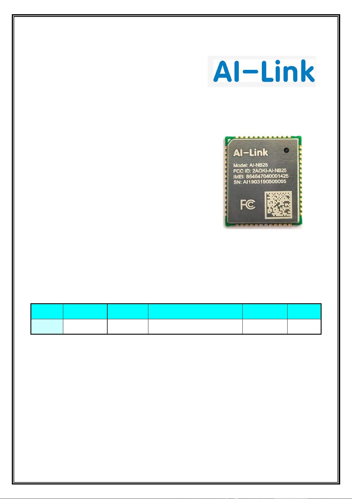
AI-NB25
NB-IoT Module
Features:
➢ Support Band
B1/B3/B5/B8
B2/B4/B12/B66/B71/B85
➢ Chip Solution
MT2625DA/MT2625DP
➢ Size& Dimension
18.7 mm x 16.0mm x 2.5mm
Model Overview
Sichuan AI-Link Technology Co.,Ltd.
Add : Anzhou,Industrial Park,Mianyang,Sichuan
Fax : +86-0816-2438701
Web site : http://www.changhong.com
FAE Tel : +86-0816-2438701
Model
Installation
Standard
Support Bands
Antenna
Note
AI-NB25
SMD
3GPP Rel-13
B1/B2/B3/B4/B5/B12/B66/B71/B85
External option
/
AI-NB25
NB-IoT Module
Sichuan AI-Link Technology Co.,Ltd. page 2 of 20
Feedback of customer’s Confirmation
We accept the specification after Confirmed
Customer name
Customer signature
Confirmation Date
Please feed back this paper and first page after your signature by the address, thanks!
ADD: Anzhou,Industrial Park,Mianyang,Sichuan
Factory: Sichuan AI-Link Technology Co.,Ltd.
Approved
Checked
Designed
Product
NB-IoT Module
Model
AI - NB25
Date
2019- 04-17
AI-NB25
NB-IoT Module
Sichuan AI-Link Technology Co.,Ltd. page 3 of 20
Record of Modification
No
Date of
modification
Main content of modification
Reason of
modification
Serial number of
modification
Confirm
1
2018-11-26
Initial release
Nicky.li
2
2018-12-16
Adding Band 66 in
support band list
Nicky.li
3
2019-01-10
Adding Antenna &
RF reference design
Nicky.li
4
2019-01-17
Adding Antenna
design indicators
Nicky.li
5
2019-03-19
Changing label to laser
marking on shiled cover
Nicky.li
6
2019-04-17
Adding 3GPPS RF standard
to RF specification
Nicky.li
7
2019-04-22
Adding FCC certification
announcement
Nicky.li
AI-NB25
NB-IoT Module
Sichuan AI-Link Technology Co.,Ltd. page 4 of 20
1. Overview
AI-NB25 is an NB-IoT module that communicates with the infrastructure of mobile network operators
through the 3GPP Rel-13 radio protocol. The core communication chip is the first NB-IoT chipset
developed by MTK. It has embedded 2MB Flash and 2MB RAM. It integrates MCU, PMU, Flash, RAM, DSP,
RF and other units. It has the characteristics of high integration and low cost.
AI-NB25 module integrates RF power amplifier PA, crystal, LDO, DC-DC, reserves eSIM card, and
reserves UART, ADC, SIM, RESET and GPIO interfaces to expand various applications. Some interfaces can
be reused to facilitate customer secondary product development.
AI-NB25 module supports work in bands B1, B2,B3,B4,B5,B12,B66,B71 and B85 . It can provide data
transmission, short message and other services, and also supports the 3GPP Rel-13 standard.
AI-NB25 module is an SMD type module with size only 18.7mm x 16.0mm x 2.5mm. There are total
54 pins. It can be embedded in various product applications through welding pad. The product size is
small and itsperipheral interface is rich.Compared with similar products, the advantage is obvious.
AI-NB25 module is the basic module for data wide communication in the field of Internet of Things. It
can provide stable and extensive communication. The application scenario is more extensive, so long as
the coverage of NB-IoT signals can support communication services.
1.1 Fundamental Performance
Projects
Information
Voltage Input
VBAT power supply voltage range: 2.1V ~ 3.63V,
typical supply voltage 3.3V
Bands
Support B1\B2\B3\B4\B5\B8\B12\B66\B71\B85
RF Power
23±2dBm
Current consumed
5uA MAX (PSM model)
Temperature range
-40°C ~ 85°C
SMS / Voice
Support SMS
SIM cards
Support only 1 set external SIM card
Antenna interface
50ohm RF impedance ( Support only 1 set external antenna)
Size
18.7mm x16.0mm x2.5mm
AI-NB25
NB-IoT Module
Sichuan AI-Link Technology Co.,Ltd. page 5 of 20
1.2 Main functions of products
◆ It supports NB-IoT B1\B2\B4\B3\B5\B8\B12\B66\B71\B85 band, provides digital transmission services,
and supports 3GPP Rel-13 standard
◆ Supports only 1 set external SIM card
◆ Supports 3 groups UARTs
◆ Supports 1 sets SPI of chip
◆ GPIO supports 32 sets of GPIOs.
◆ Supports 1 sets of ADC interfaces
◆ NB-IoT power supply 3.3V (typical value)
◆ Radio frequency antenna interface, 50 ohm standard interface
2. Application interface
The AI-NB25 module has 54 patch pins. The following sections briefly describe the
functions of each pin interface of the module.
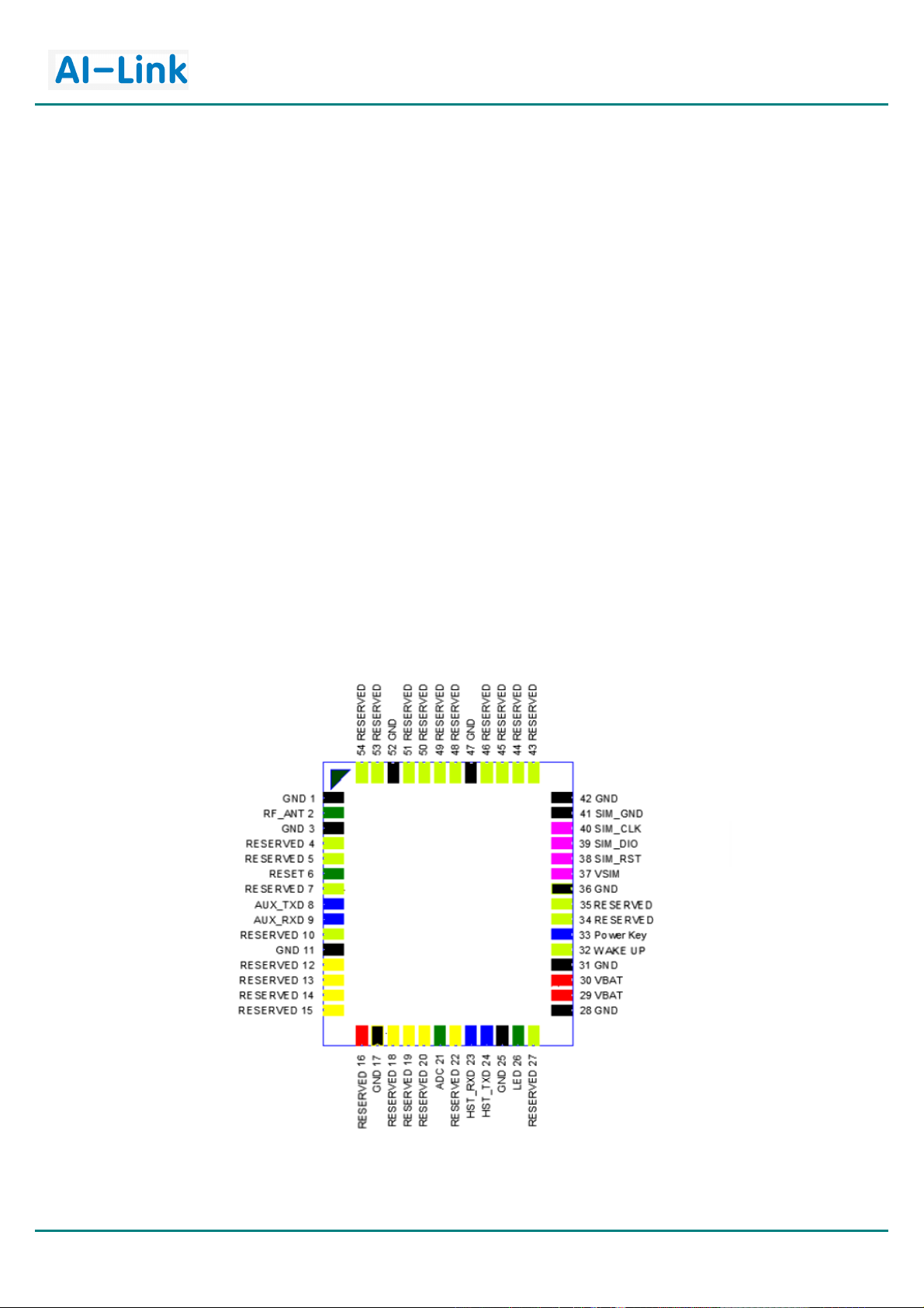
2.1 Pin Distribution
Fig. 1 Diagram of pin distribution
AI-NB25
NB-IoT Module
Sichuan AI-Link Technology Co.,Ltd. page 6 of 20
2.2 Pin Definition
Pin No
Pin Name
Type
Describe
Comments
1
GND
Ground
2
RF_ANT
I/O
Module antenna interface, RF output
50 ohm characteristic impedance
3
GND
Ground
4 RESERVED
Reserved
5 RESERVED
Reserved
6
RESET
I
Module reset pin, active low,
staging time greater than 100ms
7
RESERVED
Reserved
8 AUX_TXD
O
Auxiliary serial port, sending data
9 AUX_RXD
I
Auxiliary serial port, receive data
10
RESERVED
Reserved
11
GND
Ground
12
RESERVED
Reserved
13
RESERVED
Reserved
14
RESERVED
Reserved
15
RESERVED
Reserved
16
VDD_EXT
Reserved
17
GND
Ground
18
RESERVED
Reserved
19
RESERVED
Reserved
20
RESERVED
Reserved
21
ADC
I
Analog-to-digital conversion
22
RESERVED
Reserved
23
HST_RXD
I
Major serial port, receive data, used for AT
command and data transmission.
24
HST_TXD
O
Major serial port, sending data, used for AT
command and data transmission
25
GND
Ground
26
LED O Network indicator LED
27
RESERVED
Reserved
28
GND
Ground
29
VBAT
I
Module power supply, 2.4V ~ 3.63V,
Typical voltage 3.3V
30
VBAT
I
Module power supply, 2.4V ~ 3.63V,
Typical voltage 3.3V
31
GND
Ground
32
RTC_ENIG
I
Input GPIO port for extended RTC Interrupt
33
Power Key
I
Module boot Power Key, drop-down effective
34
RESERVED
Reserved

AI-NB25
NB-IoT Module
Sichuan AI-Link Technology Co.,Ltd. page 7 of 20
35
RESERVED
Reserved
36
GND
Ground
37
VSIM
O
Power supply voltage for external SIM card
38
SIM_RST
O
Reset external SIM card
39
SIM_DIO
I/O
External SIM card data
40
SIM_CLK
O
External SIM card clock
41
SIM_GND
Ground for External SIM card
42
GND
Ground
43
RESERVED
Reserved
44
RESERVED
Reserved
45
RESERVED
Reserved
46
GND
Ground
47
RESERVED
Reserved
48
RESERVED
Reserved
49
RESERVED
Reserved
50
RESERVED
Reserved
51
RESERVED
Reserved
52
GND
Ground
53
RESERVED
Reserved
54
RESERVED
Reserved
3. Antenna Interface
The pin 2 is the RF antenna pad. The RF interface has an impedance of 50Ω.
3.1 Pin Definition of the RF_ANT
Pin Definition of the RF_ANT table
Name
Pin
Description
GND
1
Ground
RF_ANT
2
RF antenna pad
GND
3
Ground
3.2 RF Reference Design
A reference design for RF is shown as below

AI-NB25
NB-IoT Module
Sichuan AI-Link Technology Co.,Ltd. page 8 of 20
3.3 RF Reference Design
The RF trace in host PCB connected to the module RF antenna pad should be coplanar waveguide
line microstrip line, whose characteristic impedance should be set to 50Ω. It is recommended to use
coplanar waveguide line. The characteristic impedance of coplanar waveguide line could been affected
by many factors, such as dielectric constant, distance between signal layer and reference ground(H), line
width(W), clearance between line and ground(S), copper foil thicknesses(T). The relative relationship
between those parameters could be obtained through software like CITS25, shown as follows.
Fig. 2 Coplanar Waveguide Line Structure (Software Calculation)
The reference ground would be different for different host PCB. It should set the top layer
As RF trace and set layer2 or bottom layer as reference ground for four-layer or two-layer PCB,
as shown in following figure.
Fig. 3 PCB strack recommend

AI-NB25
NB-IoT Module
Sichuan AI-Link Technology Co.,Ltd. page 9 of 20
3.4 Antenna Reference Design
AI-NB25 module provide an RF antenna (pin2) pad for antenna connection. There are two grounding
Pads just as(pin1 & pin3 )on the both sides of the antenna pad in order to give a better grounding.
Besides, π-type match circuit is suggested to be used to adjust the balanced of Antenna RF performance,
and it is better to keep match circuit close to RF_ANT port of the module.
Fig. 4 Antenna matching circuit diagram
3.5 Antenna Design Indicators
Antenna Efficiency :
Antenna efficiency is the ratio of the input power to the radiated or received
power of an antenna. The radiated power of an antenna is always lower than the input
power due to the following antenna losses: return loss, material loss, and coupling loss.
The efficiency of an antenna relates to its electrical dimensions. The following antenna
efficiency (free space) is recommended for AI-NB25 module to ensure high radio
performance of the module:
Efficiency of the antenna: ≥ 40% (below 960 MHz); ≥ 50% (over 1710 MHz)
S11 (VSWR) :
S11 indicates the degree to which the input impedance of an antenna matches the
reference impedance (50 Ω). S11 shows the resonance feature and impedance bandwidth
of an antenna. Voltage standing wave ratio (VSWR) is another expression of S11. S11 is less
important than the efficiency, and S11 has weak correlation to wireless performance.
The following S11 value is recommended for the antenna of AI-NB25 module:
S11 of the primary antenna: ≤ –6 dB
Isolation

AI-NB25
NB-IoT Module
Sichuan AI-Link Technology Co.,Ltd. page 10 of 20
For a wireless device with multiple antennas, the power of different antennas is coupled
with each other. Antenna isolation is used to measure the power coupling. The power radiated by
an antenna might be received by an adjacent antenna, which decreases the antenna radiation
Efficiency and affects the running of other devices. To avoid this problem, evaluate the antenna
isolation as sufficiently as possible at the early stage of antenna design.
Isolation recommended between the primary antenna and the other antenna: ≥15 dB
Polarization
The polarization of an antenna is the orientation of the electric field vector that rotates
with time in the direction of maximum radiation. The linear polarization is recommended
for the antenna of AI-NB25 module.
Gain and Directivity
The radiation pattern of an antenna represents the field strength of the radiated.
Gain, as another important parameter of antennas, correlates closely to the directivity.
The gain of an antenna takes both the directivity and the efficiency of the antenna into account.
Gain of the primary/diversity antenna recommended for module ≤ 2.5 dBi
4. Work Mode
The AI-NB25 module integrates baseband, RF and other units. The following sections
briefly describe each function
4.1 Boot up with module
When the VBAT power supply input reaches the minimum operating voltage, the external
RESET input keeps high level, and the module will start automatically.
4.2 Shut down with module
When the VBAT power supply is disconnected, the module will be closed.
4.3 Voltage DC supply
The input of the module's power supply uses DC voltage source, and it needs to meet the
instantaneous peak current of 0.5A at the time of transmitting pulse. The voltage drop, noise and
interference in input voltage will directly affect the performance of the module. To eliminate these
interference, ESR low 100uF tantalum capacitors, 100nF, 100pF and 33pF combinations are
recommended. Filter capacitor as close as possible to the module. The use of voltage regulator and
TVS tube is recommended for module power supply entrance.

AI-NB25
NB-IoT Module
Sichuan AI-Link Technology Co.,Ltd. page 11 of 20
4.4 Voltage Output
The power management unit of the module provides digital stable power output and provides
power for peripheral low-power devices. The output voltage and the maximum current of the pin
are as follows.
Pin Item
Pin Name
Describe
Voltage output
Voltage current
37
VSIM
SIM Power
1.8V /3.0V
150mA
4.5 Serial Port
The module contains two sets of serial interfaces for AT command transceiver, data transmission,
firmware upgrade and debugging. The major serial port can be used for AT command communication
and data transmission. The baud rate is 115 200 bps. It can also burn and upgrade firmware through
Flash tool. The baud rate of firmware upgrade is 115 200 bps.
4.6 Working Status
Active: Modules are active; all functions are available and data can be sent and received;
Modules can switch to Idle mode or PSM mode in this mode.
Idle: The module is in a shallow sleep state, the network remains connected and can receive
paging messages; in this mode, the module can switch to Active mode or PSM mode.
PSM: The module only works with RTC and is in the non-connected state of the network.
It no longer receives paging messages; however, the module needs to wake up after
RTC or external interruption
4.7 PSM mode (Power save consumption)
The maximum consumption of modules under PSM is less than 5uA. The main purpose of PSM
is to reduce module power consumption and extend battery power supply time. The following figure
shows the power consumption of modules in different modes.
Fig. 5 power consumption diagram

AI-NB25
NB-IoT Module
Sichuan AI-Link Technology Co.,Ltd. page 12 of 20
5. Electrical Characteristics
5.1 Voltage Supply
VBAT power supply must be specified, otherwise the module will be shut down, damaged and so on
Pin
Pin name
Min
Typical
Max
Unit
29
VBAT
2.1
3.3
3.63 V 30
VBAT
2.1
3.3
3.63
V
5.2 Current Supply
Item
Min
Typical
Max
Unit
Condition
PSM mode
5
uA
Sleep
Idle mode
1 mA
idle@2.56S
Active TX
330
mA
TX 23dBm
Active RX
15 mA
RX
5.3 Environmental conditions
The ambient temperature of the module must be within the specified range, otherwise
it will not guarantee stable performance and normal operation.
Temperature range
Min
Typical
Max
Unit
working temp
-40
25
85
℃
Storage temp
-40
25
125
℃
6. Radio Characteristics
6.1 Test Environmental and Diagram
Fig. 6 Test structure diagram
6.2 NB-IoT Radio characteristics

AI-NB25
NB-IoT Module
Sichuan AI-Link Technology Co.,Ltd. page 13 of 20
Frequency characteristics
Support Bands
Rx frequency
Tx frequency
B1
2110-2170 MHz
1920-1980 MHz
B2
1930-1990 MHz
1850-1910 MHz
B3
1805-1880 MHz
1710-1785 MHz
B4
2110-2155MHz
1710-1785 MHz
B5
869-894 MHz
824-849 MHz
B8
925-960 MHz
880-915 MHz
B12
729-746 MHz
699 -716MHz
B66
2110-2180 MHz
1710-1780MHz
B71
617-652 MHz
663-698 MHz
B85
728-746 MHz
698-716 MHz
TX power
Sensitivity
Support Bands
Sensitivity
Unit
B1
-113
dBm
B2
-113
dBm
B3
-113
dBm
B4
-113
dBm
B5
-113
dBm
B8
-113
dBm
B12
-113
dBm
B66
-113
dBm
B71
-113
dBm
B85
-113
dBm
Support Bands
Tx power
Offset
B1
23
±2
B2
23
±2
B4
23
±2
B5
23
±2
B8
23
±2
B12
23
±2
B66
23
±2
B71
23
±2
B85
23
±2

AI-NB25
NB-IoT Module
Sichuan AI-Link Technology Co.,Ltd. page 14 of 20
7. Mechanical Properties
7.1 Mechanical dimension drawing
Fig. 7 Top view(unit:mm)
Fig. 8 Bottom view(unit:mm)

AI-NB25
NB-IoT Module
Sichuan AI-Link Technology Co.,Ltd. page 15 of 20
7.2 Footprint recommended
Fig. 9 Dimension(unit:mm)
7.3 Products Picture View
Fig. 10 Top view Fig. 11 Bottom view

AI-NB25
NB-IoT Module
Sichuan AI-Link Technology Co.,Ltd. page 16 of 20
8. Reel Packing Template
8.1 Reel direction:
8.2 Packing diagram

AI-NB25
NB-IoT Module
Sichuan AI-Link Technology Co.,Ltd. page 17 of 20
8.3:Label template
Inner Box label
Outer Box label
Module QA
Model:
AI-NB25
(RoHS)
Box No:
Qty:
XXXX
Weight: /件
Kg
2 0 0 0 0
1
Module QA
Model:
AI-NB25
(RoHS)
Qty:
XXX
Number:

AI-NB25
NB-IoT Module
Sichuan AI-Link Technology Co.,Ltd. page 18 of 20
9. Soldering Reflow Recommendation
Heating zone: temperature: <150 C, time: 60~90 seconds, the slope is controlled at 1~3 C /S.
Preheating constant temperature zone: temperature: 150 ~ 200 c, time: 60-120 seconds,
the slope is between 0.3-0.8.
Reflow soldering area: the peak temperature is 235 C ~250 C (recommended peak
temperature is less than 245 C), and the time is 30-70 seconds.
Cooling zone: temperature: 217 C ~170 C, slope at 3~5 C /S
The solder is tin silver copper alloy lead-free solder / Sn&Ag&Cu Lead-free solder (SAC305).
Note: The product can withstand the limit temperature of 255 degrees and 5 seconds.
In order to ensure the product quality, the reflux curve should seek a balance between
PCB and components without damaging the quality of solder joints, and should be carried
out within the above curve range.

AI-NB25
NB-IoT Module
Sichuan AI-Link Technology Co.,Ltd. page 19 of 20
10. FCC Certification Announcement
According to the definition of mobile and fixed device as described in Part 2.1091(b),
this device is a mobile device.
And the following conditions must be met:
1. This Modular Approval is limited to OEM installation for mobile and fixed applications only.
The antenna installation and operating configurations of this transmitter, including any applicable
source-based time- averaging duty factor, antenna gain and cable loss must satisfy MPE categorical
Exclusion Requirements of 2.1091.
2. The EUT is a module; maintain at least a 20 cm separation between the EUT and the user’s body.
And must not transmit simultaneously with any other antenna or transmitter.
3. A label with the following statements must be attached to the host end product:
This device contains FCC ID: 2AOKI-AI-NB25
4. To comply with FCC regulations limiting both maximum RF output power and human exposure to
RF radiation, maximum antenna gain (including cable loss) must not exceed:
LTE(NB-IOT) B2/B4/B12/B66/B71 <0.95dBi
5. This module must not transmit simultaneously with any other antenna or transmitter.
6. The host end product must include a user manual that clearly defines operating requirements and
conditions that must be observed to ensure compliance with current FCC RF exposure guidelines.
For portable devices, in addition to the conditions 3 through 6 described above, a separate approval
is required to satisfy the SAR requirements of FCC Part 2.1093
If the device is used for other equipment, separate approval is required for all other
operating configurations, including portable configurations with respect to 2.1093 and different
antenna configurations.
For this device, OEM integrators must be provided with labeling instructions of finished products.
Please refer to Products Picture View FCC ID, Page 15/20 last two paragraphs:
A certified module has the option to use a permanently affixed label, or an electronic label.
For a permanently affixed label, the module must be labelled with an FCC ID - (see 2.2 Page
15/20 above). The OEM manual must provide clear instructions explaining to the OEM the
labelling requirements, options and OEM user manual instructions that are required (see next paragraph).
For a host using a certified module with a standard fixed label, if (1) the module’ss FCC ID is not visible
when installed in the host, or (2) if the host is marketed so that end users do not have straight forward
commonly used methods for access to remove the module so that the FCC ID of the module is visible;
then an additional permanent label referring to the enclosed module:“Contains Transmitter Module
FCC ID:2AOKI-AI-NB25” or “Contains FCC ID: 2AOKI-AI-NB25” must be used. The host OEM
user manual must also contain clear instructions on how end users can find and/or access the module
and the FCC ID.
The final host / module combination may also need to be evaluated against the FCC Part 15B criteria
for unintentional radiators in order to be properly authorized for operation as a Part 15 digital device.

AI-NB25
NB-IoT Module
Sichuan AI-Link Technology Co.,Ltd. page 20 of 20
The user’s manual or instruction manual for an intentional or unintentional radiator shall caution the
user that changes or modifications not expressly approved by the party responsible for compliance
could void the user's authority to operate the equipment. In cases where the manual is provided only in
a form other than paper, such as on a computer disk or over the Internet, the information required by this
section may be included in the manual in that alternative form, provided the user can reasonably be
expected to have the capability to access information in that form.
This device complies with part 15 of the FCC Rules. Operation is subject to the following two conditions:
(1) This device may not cause harmful interference, and (2) this device must accept any interference
received, including interference that may cause undesired operation.
Changes or modifications not expressly approved by the manufacturer could void the user’s authority
to operate the equipment.
To ensure compliance with all non-transmitter functions the host manufacturer is responsible for
ensuring compliance with the module(s) installed and fully operational. For example, if a host was
previously authorized as an unintentional radiator under the Declaration of Conformity procedure without
a transmitter certified module and a module is added, the host manufacturer is responsible for ensuring
thatafter the module is installed and operational the host continues to be compliant with the
Part 15B unintentional radiator requirements.
 Loading...