

Sices GC315, GC315Plus, GC400Link, GC400Mains, GC315LInk Technical Manual
...
Plus Link
Link
Mains Mains+Link
File name: EAAM045606EN.docx
Rev. 06 Date: 21/10//2015
ID Document: EAAM0456
Product: GC315xx +
GC400xxGC315 -GC315ETH

Revision
Date
Pages
Notes
00
28/03/2014
173
The first version of the manual, drawn-up for version 01.06 of
the controller.
01
21/05/2014
173
Modified section 4.2 and Chapters 3, 8 and 9.
02
19/09/2014
173
GC315Plus added
03
26/11/2014
177
Valid for the 01.11 revision of the controller: a second counter
has been added and a counter for the days left to the
maintenance. The following paragraphs have changed: 5.10.1,
5.14, 12.5.4.3, 12.5.4.10, 12.5.5.2, 14 (faults 39,40,50,57
added), 15.8, 15.10, 15.11. Chapters 12.5.2.15 and 12.5.4.10
have been added.
04
07/04/2015
177
Valid for the 01.15 revision of the controller.
The following paragraphs have changed: 8 and 9 to add device
option with max 100Vac.
05
24/06/2015
Addition of controllers GC315
Link
and GC400x. All controllers
names have been adjusted. Addition of par. 1.3. Various
paragraphs moved and added.
06
02/09/2015
Addition of controllers GC400
Mains
and GC400
Mains+Link
.
ii Technical Handbook

SUMMARY
1. Introduction ............................................................................................................ 16
1.1 Nomenclature ..................................................................................................... 16
1.2 Reference documents ......................................................................................... 16
1.3 Information on safety .......................................................................................... 17
1.4 Introduction and prerequisites ............................................................................ 17
1.5 Switch SW1 ........................................................................................................ 18
1.6 Notes on the configuration of the device parameters.......................................... 18
1.7 Definitions ........................................................................................................... 18
1.8 Conventions ........................................................................................................ 19
1.9 Software revisions .............................................................................................. 19
2. Views of the device ................................................................................................ 20
3. Technical features ................................................................................................. 24
3.1 Measurement resolution ..................................................................................... 27
3.2 Additional characteristics of GC315
Link
,GC400
Link
and GC400
Mains+Link
............... 27
4. Installation .............................................................................................................. 28
4.1 Mounting ............................................................................................................. 28
4.2 Wiring ................................................................................................................. 28
5. Connections and IN/OUT configuration .............................................................. 29
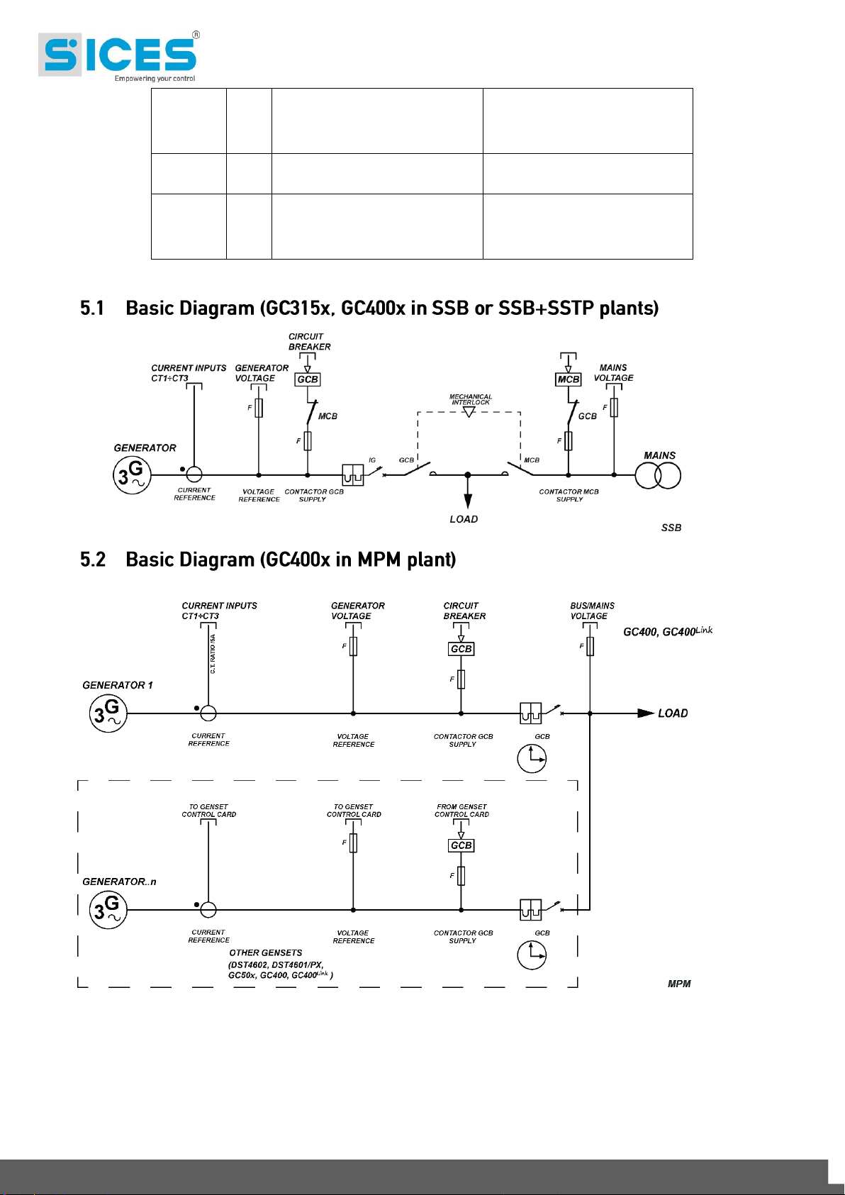
5.1 Basic Diagram (GC315x, GC400x in SSB or SSB+SSTP plants)....................... 30
5.2 Basic Diagram (GC400x in MPM plant) .............................................................. 30
5.3 Functional earth (JC) ................................................................ .......................... 31
5.4 Device (JD) supply.............................................................................................. 31
5.5 Digital inputs (JN, JM) ......................................................................................... 32
5.5.1 JN – Digital inputs ........................................................................................ 32
5.5.2 Virtual digital inputs ...................................................................................... 33
5.5.3 Configuration of the digital inputs ................................................................. 34
5.6 Digital outputs (JL, JI, JE) ................................................................................... 40
5.6.1 Engine commands (JL)................................................................................. 40
5.6.2 Outputs for JI loads change-over command ................................................. 43
5.6.3 Auxiliary outputs (JE) ................................................................................... 44
5.6.4 Digital outputs configuration ......................................................................... 45
5.6.5 AND/OR logics ............................................................................................. 50
5.7 Engine rotational speed measurement (PICK-UP or W) JM-5, JM-6, JM-7 ........ 54
5.7.1 Magnetic pick-up .......................................................................................... 54
5.7.2 W signal ........................................................................................................ 55
5.7.3 Revolutions measurement from frequency ................................................... 55
5.8 Analogue inputs (JM, JL) .................................................................................... 56
5.8.1 JM – Analogue Inputs ................................................................................... 56
5.8.2 JL-4 Analogue Input ..................................................................................... 57
5.8.3 Configuration of analogue inputs .................................................................. 58
5.8.4 Virtual ANALOGUE inputs ............................................................................ 61
5.8.5 Conversion curves ........................................................................................ 63
5.9 Analogue inputs (JQ, JR) .................................................................................... 65
5.9.1 Analogue outputs on the controller (only GC400x) ....................................... 65
5.9.2 Configuration of the ANALOGUE outputs..................................................... 65
5.10 Optional additional modules ......................................................................... 66
Technical Handbook iii

5.11 Connection to the public electric mains/parallel bars (JH) ............................ 67
5.11.1 Measurement of the mains neutral .......................................................... 68
5.12 Connection to the genset (JG) ...................................................................... 68
5.12.1 Measurement of the generator neutral .................................................... 69
5.13 Current transformer connection (JF) ............................................................ 70
5.13.1 Auxiliary current ...................................................................................... 71
5.14 Communication ............................................................................................ 72
5.14.1 Serial port 1 RS232 (JA) – Not available for GC315 .............................. 72
5.14.2 Serial port 2 RS485 (JO) – Not available for GC315 ............................... 73
5.14.3 USB (JB) ....................................................................................................... 74
5.14.4 Ethernet (JS) – Not available on GC315, GC315
Link
and GC400
Link
.............. 75
5.15.1 CAN-BUS (JO) connection – not available for GC315 ....................................... 77
5.15.2 CAN-BUS (JP) connection – only available for GC400x .................................... 78
This CAN-BUS interface is only available for GC400x and must only be used for plants
composed by more than one generator (MPM). It is useful to connect all SICES genset
controllers to each other (not necessarily only GC400x): through this communication
channel (PMBC – Power Management Communication Bus) the controllers exchange
all necessary data to manage the parallel functions (see doc. [12]). ............................ 78
The CAN-BUS interface is galvanically isolated. The bus itself can be also used for the
connection to the optional modules DITHERM, DIGRIN, DIVIT, DITEL and DANOUT: in
this case it is also required the use of a CAN-BRIDGE module to avoid that the
expansion modules data of a controller are sent to the other controllers connected to
this CAN-BUS too (see 5.10). ....................................................................................... 78
Connections: ................................................................................................................ 78
6. Link Controllers ..................................................................................................... 79
6.1 Preface ............................................................................................................... 79
6.2 HW Configuration ............................................................................................... 80
6.2.1 SIM insertion ................................................................................................ 81
6.2.2 GSM e GPS antenna .................................................................................... 82
6.2.3 Warning LED ................................................................................................ 82
6.3 Internal battery as option .................................................................................... 83
6.3.1 Connection/disconnection and recharge of the internal battery .................... 84
6.4 Parameters configuration .................................................................................... 85
6.4.1 GPRS/GSM Modem and SMS messages .................................................... 85
6.4.2 GPRS Configuration ..................................................................................... 86
6.4.3 GPS Receiver ............................................................................................... 86
6.5 “Si.Mo.Ne” system .............................................................................................. 87
6.6 Energy saving mode ................................................................ ........................... 88
7. Main functions ....................................................................................................... 90
7.1 Front panel GC315x ........................................................................................... 90
7.2 Front Panel GC400x ........................................................................................... 91
7.3 Front Panel GC400
Mains
and GC400
Mains+Link
....................................................... 92
7.4 Selector (ref. to fig. 1) ................................ ......................................................... 93
7.5 Indicators (ref. to fig. 1 and 2) ............................................................................. 96
7.6 Multifunctional display ......................................................................................... 98
7.6.1 LCD lighting .................................................................................................. 98
7.6.2 Contrast adjustment ..................................................................................... 98
7.6.3 Mode navigation ........................................................................................... 98
iv Technical Handbook

7.6.4 Display area layout (ref. to fig. 4) .................................................................. 99
7.6.5 Top status bar (ref. to fig. 5) ....................................................................... 100
7.7 Display mode .................................................................................................... 101
7.7.1 Programming (P.XX) ................................................................................. 101
7.7.2 Status information (S.xx) ................................................................ ............ 108
7.7.3 Electrical measurements (M.xx) ................................................................. 114
7.7.4 Engine measurements (E.xx) ..................................................................... 118
7.7.5 Measures from CAN-BUS PMCB (only for GC400x) (B.xx), ....................... 122
7.7.6 History logs (H.xx) ...................................................................................... 124
7.8 Selection of the language ................................................................................. 132
8. Working sequence ............................................................................................... 133
8.1 Operating modes .............................................................................................. 133
8.2 Mains ................................................................................................................ 136
8.2.1 Internal sensor ............................................................................................ 137
8.2.2 External sensor .......................................................................................... 141
8.2.3 Mains global status ..................................................................................... 141
8.2.4 Communication and events ........................................................................ 141
8.3 Generator ......................................................................................................... 142
8.3.1 Frequency .................................................................................................. 142
8.3.2 Voltages ..................................................................................................... 143
8.3.3 Overview .................................................................................................... 145
8.3.4 Communication and events ........................................................................ 145
8.4 Automatic intervention of the generator inhibited. ............................................. 145
8.4.1 Inhibition from contact ................................................................................ 146
8.4.2 Inhibition from clock .................................................................................... 146
8.5 Differences between Mains Simulation and Inhibition ...................................... 146
8.6 Engine .............................................................................................................. 147
8.6.1 Engine running/stopped status acknowledgement ..................................... 147
8.6.2 Engine commands ...................................................................................... 148
8.6.3 Manual control sequence ........................................................................... 149
8.6.4 Communication and events ........................................................................ 154
8.7 Breakers management ..................................................................................... 156
8.7.1 Digital outputs ............................................................................................. 156
8.7.2 Digital inputs ............................................................................................... 157
8.7.3 OFF/RESET management logic ................................................................. 158
8.7.4 MAN management logic ............................................................................. 158
8.7.5 Switching logic in AUTO mode .................................................................. 159
8.7.6 Switch ......................................................................................................... 159
8.7.7 Switch management ................................................................................... 159
8.7.8 Automatic power delivery of the generator inhibited. .................................. 159
8.7.9 Communication and events ........................................................................ 160
9. Anomalies ............................................................................................................ 162
9.1 Silencing the horn ............................................................................................. 163
9.2 Acknowledging anomaly ................................................................................... 163
9.3 Acknowledging anomaly ................................................................................... 164
9.4 Communication and events .............................................................................. 164
9.5 Protection OVERRIDE ...................................................................................... 165
9.6 Anomalies related to digital inputs .................................................................... 166
9.7 Anomalies related to analogue inputs ............................................................... 168
Technical Handbook v

9.8 Anomalies list ................................................................................................... 168
01 – Minimum generator voltage ................................................................................ 168
02 – Maximum generator voltage ............................................................................... 169
03 – Minimum generator frequency ............................................................................ 169
04 – Maximum generator frequency ........................................................................... 169
05 – Belt break (D+ battery-charger failure) ............................................................... 170
06 – Maximum current ................................................................................................ 170
07 – Manual stop while in AUTO ................................................................................ 172
08 – Operating conditions failure ................................................................................ 173
11 – Power reverse .................................................................................................... 173
13 – Mains circuit breaker (MCB) not closed .............................................................. 173
14 – Genset circuit breaker (GCB) not closed ............................................................ 173
16 – Short circuit on the generator ............................................................................. 174
17 – Overspeed (from contact) ................................................................................... 174
18 – Overspeed (from engine speed measurement) .................................................. 175
19 – Overspeed (from generator frequency) .............................................................. 175
21 – Failed stop .......................................................................................................... 175
22 – Overcrank ........................................................................................................... 176
23 – Mains circuit breaker (MCB) not open ................................................................ 176
24 – Genset circuit breaker (GCB) not open .............................................................. 176
26 – Minimum fuel level (from ANALOGUE sensor) ................................................... 177
27 – Low fuel level (from contact) ............................................................................... 177
28 – Low fuel level (from ANALOGUE sensor) ........................................................... 178
29 – High fuel level (from contact) .............................................................................. 178
30 – High fuel level (from ANALOGUE sensor) .......................................................... 178
31 – High coolant temperature (from contact) ............................................................ 178
32 – High coolant temperature (from ANALOGUE sensor) ........................................ 179
33 – Maximum coolant temperature (from contact) .................................................... 179
34 – Maximum coolant temperature (from ANALOGUE sensor) ................................ 180
35 – Maximum oil temperature (from ANALOGUE sensor) ........................................ 180
37 – Starter battery voltage, low ................................................................................. 180
38 – Starter battery voltage, high................................................................................ 181
39 – Service required (first counter) ........................................................................... 181
40 – Service required (second counter) ...................................................................... 181
41 – Minimum oil pressure (from contact) .................................................................. 182
42 – Minimum oil pressure (from ANALOGUE sensor) .............................................. 182
43 – Low oil pressure (from contact) .......................................................................... 183
44 – Low oil pressure (from ANALOGUE sensor) ...................................................... 183
45 – Maximum auxiliary current .................................................................................. 183
48 – Emergency stop .................................................................................................. 184
49 – Maximum power ................................................................................................. 184
50 – Service required (days counter) .......................................................................... 184
52 – Generator voltages asymmetry ........................................................................... 185
53 – Generator current asymmetry ............................................................................. 185
54 – High oil temperature (from ANALOGUE sensor) ................................................ 185
55 – Wrong phase sequence ...................................................................................... 186
56 – Low generator voltage ........................................................................................ 186
57 – Clock not valid ................................................................................................ .... 186
58 – Low generator frequency .................................................................................... 187
59 – High generator voltage ....................................................................................... 187
vi Technical Handbook

60 – High generator frequency ................................................................................... 187
61 – Lost Excitation .................................................................................................... 188
64 – Fuel pump failure ................................................................................................ 188
65 – Low coolant temperature (from ANALOGUE sensor) ......................................... 189
98 – Maximum time without CAN-BUS data (engine) ................................................. 189
100 – Maximum differential current ............................................................................ 189
105 – Battery charger failure (from CAN-BUS). .......................................................... 189
106 – Maximum reactive power exported (only GC400x) ...................................... 190
118 – Maximum speed from CAN BUS ...................................................................... 190
132 – High coolant temperature from CAN-BUS ........................................................ 190
134 – Maximum coolant temperature from CAN-BUS ................................................ 190
135 – Minimum coolant level from CAN-BUS. ............................................................ 191
136 – Low coolant level from CAN BUS ..................................................................... 191
137 – Low battery voltage from CAN BUS ................................................................. 191
142 – Minimum oil pressure from CAN BUS .............................................................. 191
144 – Low oil pressure from CAN BUS ...................................................................... 192
158 – High oil temperature from CAN BUS ................................................................ 192
159 – Maximum oil temperature from CAN BUS ........................................................ 192
160 – Water in fuel from CAN BUS ............................................................................ 192
198 – Warnings – Yellow lamp (from CAN-BUS) ........................................................ 193
199 – Alarms cumulative – Red lamp (from CAN-BUS) ............................................. 193
200 – CAN-BUS connection 1 (PMCB) failed (only GC400x) ................................ 193
201 – Address conflict on CAN-BUS bus 1 (PMCB) (only GC400x) ...................... 193
202 – Errato numero di generatori sul bus CAN-BUS 1 (PMCB) (solo GC400x) ... 194
203 – Negative sequence ........................................................................................... 194
204 – Failed closure of NECB breaker (only GC400x) .......................................... 194
205 – Failed opening of NECB breaker (only GC400x) ......................................... 194
252 – CAN-BUS (EXBUS) expansion modules missing ............................................. 195
253 – CAN-BUS (EXBUS) missing measure .............................................................. 195
254 – CAN-BUS (EXBUS) duplicate address ............................................................. 195
255 - Connection with CAN-BUS (EXBUS) sensor timed out. .................................... 195
271 – Input parallel failed (only GC400x) ............................................................... 196
272 – Mancato parallelo di rientro (solo GC400x).................................................. 196
273 – Incoherent parameters (only GC400x) ......................................................... 196
274 – Sectioned auto production line (only GC400x) ............................................. 196
275 – Interface device not open (only GC400x)..................................................... 197
276 – Alarm from CAN-BUS master controller 1 (PMCB) (only GC400x) .............. 197
279 – Bar voltage not coherent (only GC400x) ...................................................... 197
10. Other functions .................................................................................................... 197
10.1 Fuel pump ......................................................................................................... 197
10.1.1 Use with an ANALOGUE level transducer ............................................ 198
10.1.2 To use this function requires: ................................................................ 199
10.1.3 Level evaluation .................................................................................... 199
10.1.4 Automatic pump control ........................................................................ 199
10.1.5 Manual pump control............................................................................. 200
10.1.6 Protections ............................................................................................ 200
10.2 Engine Coolant preheating ............................................................................... 200
10.3 Loads protection from mains breaker damages ................................................ 200
10.4 Load thresholds ................................................................................................ 202
10.4.1 Low load ................................................................................................ 202
Technical Handbook vii

10.4.2 High load ............................................................................................... 202
10.5 Alternative parameters configuration ................................................................ 203
10.6 EJP function ..................................................................................................... 204
10.7 Maintenance ..................................................................................................... 205
10.7.1 Counter for the hours left to maintenance 1 ................................................ 205
10.7.2 Counter for the hours left to maintenance 2 .......................................... 206
10.7.3 Counter for the days left to maintenance .................................................... 206
10.8 Counters ........................................................................................................... 206
10.8.1 Counters reset ...................................................................................... 208
10.9 Clock ................................................................................................................. 208
10.9.1 Automatic update of the clock ............................................................... 208
10.9.2 Engine TEST start-up weekly planning. ................................................ 209
10.9.3 Weekly scheduling of engine operating time intervals. ......................... 209
10.10 Non-volatile memory .................................................................................. 210
viii Technical Handbook

INDEX
A
AIF.0000 43; 60
AIF.0100 60
AIF.1000 60; 61
AIF.1001 60
AIF.1100 60; 61; 179
AIF.1101 60; 174; 179
AIF.1110 60; 61
AIF.1111 60
AIF.1200 60; 61
AIF.1201 60
AIF.1210 60; 61
AIF.1211 60
AIF.1220 60; 61
AIF.1221 60
AIF.1300 43; 60; 142; 163
AIF.1601 60
AIF.1603 60
AIF.1605 60
AIF.1641 60
AIF.2001 58; 60; 64; 118
AIF.2003 58; 60; 64; 118
AIF.2005 58; 60; 64; 118
AIF.2051 58; 60
AIF.2101 60
AIF.2103 60
AIF.2105 60
AIF.2107 61
AIF.2109 61
AIF.2111 61
AIF.2201 61
AIF.2211 61
AIF.2301 61
AIF.2303 61
AIF.2305 61
AIF.2307 61
AIF.2401 61
AIF.2403 61
AIF.2405 61
AOF.0000 65
AOF.0102 65
AOF.1000 65
AOF.1001 65
AOF.1002 65
AOF.1003 65
AOF.3001 65; 66
AOF.3011 65
AOF.3013 65
AOF.3015 65
AOF.3023 65
AOF.3025 65
AOF.3035 66
AOF.3101 64; 66
AOF.3111 66
AOF.3121 66
AOF.3201 66
AOF.3211 66
AOF.3221 66
D
DIF.0000 34; 35
DIF.1001 35; 152
DIF.1002 35; 152
DIF.1003 35; 152
DIF.1004 35; 152
DIF.1031 36; 152
DIF.1032 36; 152
DIF.1033 36; 152
DIF.1034 36; 152
DIF.2001 36; 158
DIF.2031 36; 131
DIF.2032 36; 131
DIF.2033 36; 144
DIF.2034 36; 148
DIF.2061 36; 146
DIF.2062 36; 39; 159
DIF.2063 36; 39; 159
DIF.2064 36; 159
DIF.2092 36
DIF.2093 36
DIF.2094 36
DIF.2095 36
DIF.2096 36
DIF.2099 36
DIF.2121 36
DIF.2151 36; 198
DIF.2152 36; 198
DIF.2153 37; 198
DIF.2154 37; 198
DIF.2181 37
DIF.2211 37
DIF.2241 37
DIF.2242 37
DIF.2243 37
DIF.2271 37; 129
DIF.2272 37; 129
DIF.2273 37; 129
DIF.2330 37
DIF.2331 37
DIF.2332 37
DIF.2333 37
DIF.2501 34; 37; 141
DIF.2502 37; 154; 199
DIF.2701 37; 131; 199
DIF.2702 34; 37
DIF.2703 37; 196; 197
DIF.2704 37; 71; 177
DIF.2705 37
DIF.2706 37; 130; 131; 145; 148; 157; 158
DIF.2708 37
DIF.2709 38; 145
DIF.2710 38
DIF.2711 38
Technical Handbook ix

DIF.2712 38
DIF.2713 38
DIF.2714 38
DIF.2715 38
DIF.2716 38
DIF.3001 34; 38; 151; 167; 170
DIF.3002 38; 151; 167; 170
DIF.3003 38
DIF.3004 38
DIF.3005 38; 188
DIF.3101 38; 132; 136
DIF.3102 38
DIF.3103 38
DIF.3201 38; 107
DIF.3202 38; 107
DIF.3203 38; 107
DIF.3204 38; 107
DIF.3205 38; 107
DIF.3206 39; 107
DIF.3301 39; 193
DIF.3302 39; 193
DIF.4001 34; 39; 160
DIF.4002 39; 160
DIF.4003 39; 160
DIF.4004 34; 39; 160
DIF.4011 39; 161
DIF.4012 39; 160; 161
DIF.4013 39; 160; 161
DIF.4014 39; 160; 161
DIF.4021 39; 161
DIF.4022 39; 161
DIF.4023 39; 161
DIF.4024 39; 161
DIF.4031 39; 161
DIF.4032 39; 161
DIF.4033 39; 161
DIF.4034 39; 161
DIF.4041 39; 161
DIF.4042 40; 161
DIF.4043 40; 161
DIF.4044 40; 161
DIF.4051 40; 161; 194
DIF.4052 40; 161
DIF.4053 40; 161
DIF.4054 40; 161
DIF.4062 40; 160; 161
DIF.4063 40; 160; 161
DIF.4064 40; 160; 161
DIF.4211 40; 160; 171; 193
DIF.4212 34; 40; 171; 193
DIF.4213 40; 172; 193
DIF.4221 34; 40; 143; 145; 176
DIF.4222 40; 143; 145; 177
DIF.4231 40; 172; 173
DIF.4232 34; 40
DIF.4241 40; 168
DIF.4251 40; 168
DIF.4261 41; 190
DOF.0000 46; 47
DOF.0102 47
DOF.0103 47; 50
DOF.1001 47; 144
DOF.1002 47; 144
DOF.1003 41; 47; 144
DOF.1004 39; 40; 47; 144
DOF.1005 41; 47; 144
DOF.1006 46; 47; 144
DOF.1007 47; 144; 146
DOF.1008 47; 147
DOF.1009 47; 147
DOF.1031 47; 194
DOF.1032 47; 182; 192
DOF.1033 47; 144
DOF.1034 47; 192
DOF.2001 47; 150; 151
DOF.2002 47; 150
DOF.2003 47; 150
DOF.2004 44; 47; 151; 170
DOF.2031 47; 151
DOF.2032 44; 47; 151
DOF.2033 44; 47; 151
DOF.2034 44; 47; 151; 154; 170
DOF.2061 47; 188
DOF.2091 47
DOF.2092 47
DOF.3001 48; 132
DOF.3002 48; 132
DOF.3003 48; 132
DOF.3004 48; 132
DOF.3005 48; 132
DOF.3011 48; 132
DOF.3012 48; 132
DOF.3031 48
DOF.3032 48; 140
DOF.3033 48; 137
DOF.3034 48
DOF.3035 48
DOF.3036 48
DOF.3037 48
DOF.3061 48
DOF.3062 48
DOF.3091 48
DOF.3092 48
DOF.3093 48
DOF.3094 48
DOF.3095 48
DOF.3096 48
DOF.3121 48; 196
DOF.3151 48; 158
DOF.3152 46; 48; 156; 158
DOF.3153 48
DOF.3180 48
DOF.3181 48
DOF.3182 48
DOF.3183 48
DOF.3184 48
DOF.4001 48; 158
DOF.4002 48; 158
DOF.4003 48; 158
DOF.4004 48; 158
x Technical Handbook

DOF.4005 48; 158
DOF.4031 48; 158
DOF.4032 49; 158
DOF.4033 49; 159
DOF.4034 50; 159
DOF.4035 50; 159
E
EVT.1001 122; 132
EVT.1002 122; 132
EVT.1003 122; 132
EVT.1004 122; 132
EVT.1005 122; 132
EVT.1010 122; 137
EVT.1011 122; 137
EVT.1012 122; 137
EVT.1013 122; 141
EVT.1014 122; 141
EVT.1020 122; 140
EVT.1021 122; 140
EVT.1022 122; 140
EVT.1030 122; 155
EVT.1031 122; 155
EVT.1032 122; 155
EVT.1033 122; 155
EVT.1035 122; 155
EVT.1036 122; 155
EVT.1037 122; 155
EVT.1038 122; 155
EVT.1040 122; 149
EVT.1041 122; 149
EVT.1042 122; 149
EVT.1043 122; 149
EVT.1044 122; 149
EVT.1045 122; 149
EVT.1050 122; 149
EVT.1051 122; 149
EVT.1052 122; 149
EVT.1053 122; 149
EVT.1054 122; 149
EVT.1055 122; 149
EVT.1056 122; 149
EVT.1057 122; 150
EVT.1058 122; 150
EVT.1059 122; 150
EVT.1060 122; 150
EVT.1061 122; 150
EVT.1062 122; 150
EVT.1063 122; 150
EVT.1070 123
EVT.1071 123
EVT.1074 123
EVT.1075 123
EVT.1076 123; 202
EVT.1077 123
EVT.1078 123
EVT.1080 123; 155
EVT.1081 123; 155
EVT.1082 123; 160
EVT.1083 123; 160
EVT.1091 123
EVT.1092 123
EVT.1093 123
EVT.1094 123
EVT.1095 123
EVT.1096 123
EVT.1097 123
EVT.1098 123
EVT.1099 123
EVT.1100 123
EVT.1101 123
EVT.1102 123
EVT.1103 123
EVT.1104 123
EVT.1105 123
EVT.1151 123
EVT.1152 123
EVT.1153 123
EVT.1154 123
EVT.1155 123
EVT.1156 123
EVT.1157 123
EVT.1158 123
EVT.1160 123
EVT.1161 123
EVT.1162 123
EVT.1163 123
EVT.1164 123
EVT.1165 123
P
P.0000 98; 99
P.0001 98; 99
P.0002 98; 99
P.0003 98; 99
P.0004 130; 131; 144; 145; 148; 153; 154; 157;
158
P.0101 69; 138; 162; 163; 164; 168; 179; 180;
181; 197
P.0102 101; 138; 139; 162; 163; 164; 168; 179;
180; 181; 197
P.0103 69; 138; 197
P.0104 69; 138; 197
P.0105 133; 134; 137; 163; 169; 181; 197
P.0106 101; 163; 164; 168; 179; 188; 197
P.0107 71; 197
P.0108 71; 177; 197
P.0109 197
P.0110 55; 142; 169
P.0111 55; 142; 169
P.0116 132; 133; 134; 135; 197
P.0117 68; 133; 197
P.0118 68; 133; 197
P.0119 68; 133; 197
P.0124 71; 113; 197
P.0125 167; 178; 196; 197
P.0126 67; 133; 197
P.0127 55; 142; 169
P.0128 69; 198
P.0129 68; 198
Technical Handbook xi

P.0130 71; 198
P.0131 71; 112; 177; 198
P.0133 97; 169; 198
P.0134 169; 198
P.0135 198
P.0139 71; 198
P.0140 66; 71; 177
P.0141 66; 188; 189
P.0142 66; 188; 189
P.0143 66; 189
P.0144 66; 189
P.0151 69; 138
P.0152 68; 133
P.0201 133; 134
P.0202 137; 138; 139; 162; 180; 181
P.0203 133; 134
P.0204 133; 134
P.0207 141
P.0208 141
P.0209 145
P.0210 144
P.0211 146; 170
P.0212 146
P.0213 149
P.0214 149; 169
P.0215 148
P.0216 39; 40; 161; 172; 173; 174; 176; 177; 179;
180; 188
P.0217 147; 166
P.0218 48
P.0219 45; 154
P.0220 45; 154
P.0221 167; 195
P.0222 129
P.0223 146
P.0224 142
P.0225 142
P.0226 138; 139; 143
P.0227 139; 143
P.0228 137; 143
P.0229 137; 138; 143
P.0230 43; 142; 163
P.0231 43; 142; 163
P.0232 142
P.0233 146
P.0234 42; 149
P.0235 153
P.0236 133; 134
P.0237 133; 134
P.0238 133; 135
P.0239 133; 135
P.0241 146
P.0242 145
P.0244 133; 135
P.0246 150
P.0247 151
P.0301 139; 140; 162
P.0302 140; 162
P.0303 139; 140; 162
P.0304 140; 162
P.0305 137; 138; 163
P.0306 138; 163
P.0307 137; 138; 163
P.0308 138; 163
P.0309 163; 164
P.0310 163; 164; 165
P.0311 168
P.0312 168
P.0313 167
P.0314 167
P.0315 179
P.0316 179
P.0317 179
P.0318 179
P.0319 180
P.0320 180
P.0321 182
P.0322 182
P.0323 164; 165; 168
P.0324 164; 165; 166; 168
P.0325 188
P.0326 183; 188
P.0328 138; 139; 162; 180; 181
P.0331 169
P.0332 169
P.0333 169
P.0334 169
P.0335 173
P.0336 173
P.0337 58; 173; 174
P.0338 174
P.0339 145; 177
P.0340 177
P.0341 145; 176
P.0342 176
P.0343 172; 193
P.0344 172
P.0345 172; 193
P.0346 172
P.0347 171; 193
P.0348 171
P.0349 43; 163
P.0350 178
P.0351 178
P.0352 178
P.0353 182; 183
P.0354 183
P.0355 194; 195
P.0356 194; 195
P.0357 43; 163
P.0361 178
P.0362 174
P.0363 174
P.0364 175
P.0365 175
P.0367 71; 177
P.0368 71; 177
P.0373 179; 180
P.0374 179; 180
P.0375 174
xii Technical Handbook

P.0376 174
P.0377 71; 183
P.0378 71; 183
P.0379 184
P.0380 184
P.0391 180
P.0392 180
P.0393 181
P.0394 181
P.0395 181
P.0396 181
P.0397 181
P.0398 181; 182
P.0400 192
P.0401 193
P.0402 193
P.0403 193
P.0404 182; 194
P.0405 192
P.0406 192
P.0409 202; 203
P.0410 202; 203
P.0418 130; 180; 181; 203
P.0419 130; 203
P.0420 130; 180; 181; 203
P.0421 141; 180; 181; 204
P.0422 141; 180; 181; 204
P.0423 141; 180; 181; 204
P.0424 175; 199; 200; 202
P.0425 175; 199; 200
P.0426 131
P.0427 131
P.0428 131
P.0436 175; 176; 200; 202
P.0437 175; 176; 200
P.0438 178; 181; 200
P.0441 121; 131; 137; 140; 141; 149; 155
P.0442 124; 125
P.0443 124; 126
P.0450 84
P.0451 73; 115
P.0452 73; 187
P.0453 73
P.0454 73
P.0456 76; 84
P.0469 99; 100
P.0470 73
P.0472 74
P.0473 74
P.0474 74
P.0475 74
P.0478 75
P.0479 75
P.0481 196
P.0482 197
P.0483 196; 197
P.0484 196
P.0485 196; 197
P.0486 197
P.0491 157
P.0492 94
P.0493 94
P.0494 111
P.0495 91; 92; 144; 148; 166
P.0500 75; 76
P.0501 75; 76
P.0502 75; 76
P.0503 75; 76
P.0504 75
P.0505 75
P.0508 75; 76
P.0509 75; 76
P.0510 75; 76
P.0511 75; 76
P.0513 75
P.0514 75
P.0530 86; 110
P.0531 86
P.0532 86
P.0533 86
P.0534 86
P.0535 86
P.0536 86
P.0537 86
P.0539 86
P.0542 86
P.0551 85
P.0552 85
P.0553 85
P.0554 85
P.0555 85
P.0556 85
P.0557 85
P.0558 85
P.0559 85
P.0580 85
P.0581 86
P.0582 86
P.0583 85
P.0584 85
P.0700 78; 115; 116; 117; 127; 143; 169; 173;
174; 176; 177; 179; 182; 183; 184; 185; 186;
187
P.0703 78; 182
P.0704 183; 184; 185; 186; 187
P.0709 182; 183
P.0710 146
P.0711 183
P.0800 78; 119; 187; 188; 191
P.0802 189; 190; 191
P.0803 187; 188
P.0804 154
P.0840 38
P.0847 152
P.0852 189; 190
P.0853 190
P.0854 152; 189; 190
P.0855 152; 154; 190
P.0856 65
P.0857 65
Technical Handbook xiii

P.0862 65
P.0863 65
P.0880 36
P.0884 36; 38
P.0900 190
P.0902 36
P.0922 37
P.0924 37
P.0974 38
P.1604 198
P.1605 198
P.2000 35
P.2001 35; 160; 167; 168; 170; 171; 172; 173;
176; 177; 190; 194; 195; 196; 199
P.2002 35; 151; 160; 161; 167; 168; 170; 171;
172; 173; 176; 177; 190; 194; 195; 199
P.2003 35; 160; 194
P.2004 199
P.2100 35
P.2151 34
P.2152 34
P.2153 34
P.2200 35
P.2250 35
P.3000 46; 47
P.3001 144; 182; 188; 196
P.3005 42
P.3006 42
P.3200 46
P.3201 182
P.3250 46; 47
P.4017 58; 176; 177
P.4018 58; 118
P.4019 58
P.4020 58
P.4021 58
P.4022 58
P.4023 58
P.4024 58
P.4025 173; 174; 179; 182; 183
P.4033 171; 172; 174
P.4041 43; 57; 142; 163
P.4051 59
P.4052 59
P.4053 59
P.4054 59
P.4055 59
P.4056 59
P.4057 59
P.4058 59
P.4131 174
P.6001 65
P.6002 65
S
ST_000 51
ST_001 51
ST_002 51
ST_003 51
ST_004 52
ST_008 52
ST_009 52
ST_010 52
ST_011 52
ST_012 52
ST_013 52
ST_014 52
ST_015 52
ST_016 52
ST_017 52
ST_018 52
ST_019 52
ST_020 52
ST_024 52
ST_025 52
ST_026 52
ST_027 52
ST_028 52
ST_032 52
ST_033 52
ST_035 52
ST_036 52
ST_037 52
ST_038 52
ST_039 52
ST_040 52
ST_041 52
ST_048 52
ST_051 52
ST_052 52
ST_053 52
ST_054 52
ST_055 52
ST_056 52
ST_057 52
ST_058 52
ST_059 52
ST_060 52
ST_061 52
ST_062 52
ST_063 52
ST_064 52
ST_065 52
ST_066 52
ST_068 52
ST_069 52
ST_070 52
ST_071 52
ST_072 52
ST_073 52
ST_074 52
ST_075 52
ST_080 52
ST_081 52
ST_082 52
ST_083 52
ST_084 52
ST_085 52
ST_088 52
ST_089 52
xiv Technical Handbook

ST_090 52
ST_091 52
ST_092 52
ST_093 52
ST_096 52
ST_097 52
ST_098 52
ST_099 52
ST_100 53
ST_101 53
ST_102 53
ST_103 53
ST_104 53
ST_108 53
ST_109 53
ST_110 53
ST_111 53
ST_112 53
ST_113 53
ST_114 53
ST_128 53
ST_129 53
ST_130 53
ST_131 53
ST_132 53
ST_133 53
ST_134 53
ST_135 53
ST_136 53
ST_144 53
ST_145 53
ST_146 53
ST_147 53
ST_148 53
ST_149 53
ST_150 53
ST_151 53
ST_152 53
ST_153 53
ST_154 53
ST_155 53
ST_156 53
ST_157 53
ST_158 53
ST_159 53
ST_176 53
ST_998 53
ST_999 53
Technical Handbook xv
Controller
USB
RS232
RS485
Ethernet
Modem
GPRS
included
CAN
engine
CAN
sharing
ANALOGUE
outputs
GC315
Yes
GC315
Plus
Yes
Yes
Yes
Yes
Yes
Yes
Yes
Yes
GC315
Link
Yes
Yes
Yes
Yes
Yes
Yes
Yes
Yes
GC400x
Yes
Yes
Yes
Yes
Yes
Yes
Yes
Yes
GC400
Link
Yes
Yes
Yes
Yes
Yes
Yes
Yes
Yes
GC400
Mains
Yes
Yes
Yes
Yes
Yes
Yes
Yes
Yes
GC400
Mains+Link
Yes
Yes
Yes
Yes
Yes
Yes
Yes
Yes
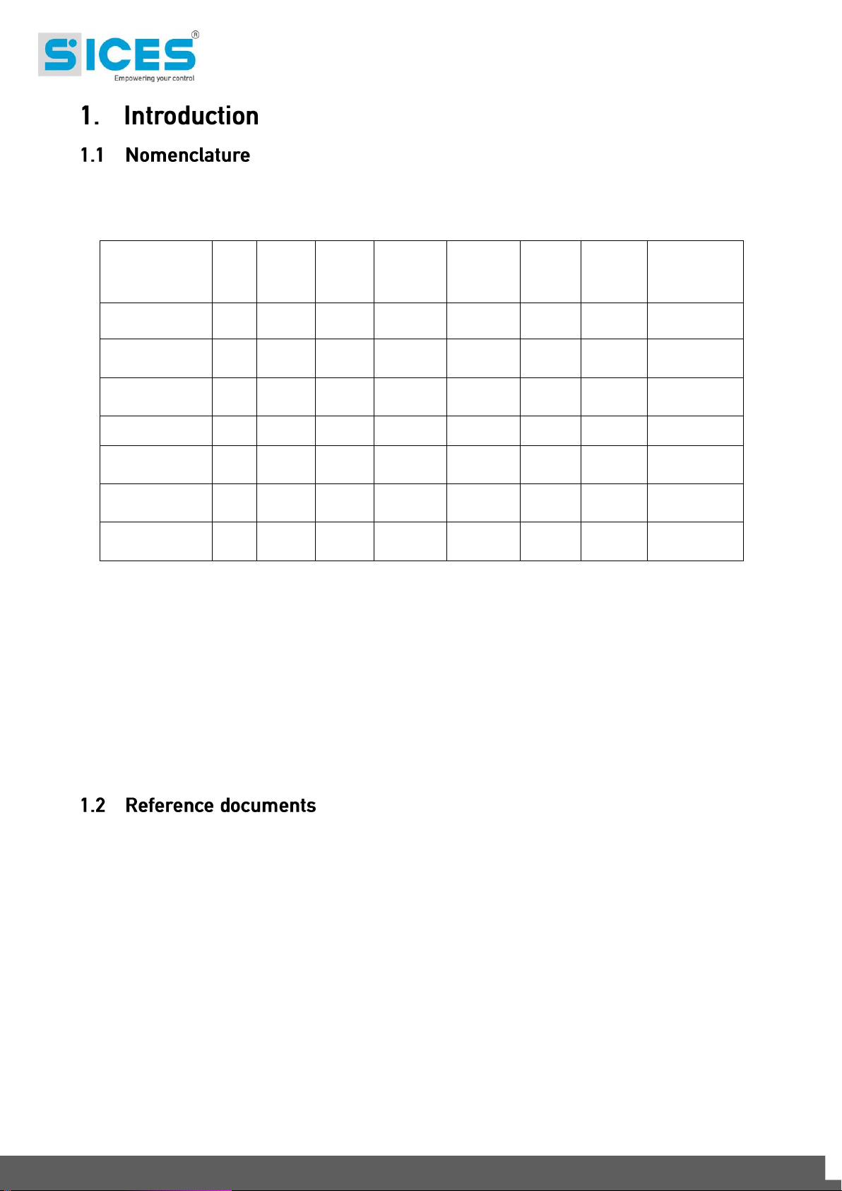
This manual is valid for all models of the controllers GC315 and GC400. The controllers
models are different in the communication options available and in the presence of
ANALOGUE outputs. The following table shows the options available on each model.
In the manual, when referring to the controllers, the model name will be used to refer to the
specific model. Otherwise:
GC315x: to refer to all models GC315, GC315
GC400x: to refer to all models GC400, GC400
Link
, GC315
Link
, GC400
Plus
.
Mains
and GC400
Mains+Link
In order to avoid misunderstanding, the basic models GC315 and GC400 will be referred as
GC315x and GC400x: they are used only in the manual, they do not appear on the
controller front facia.
[1] SICES EAAM0448xx Parameters Table GC315.
[2] SICES EAAM0504xx Parameters Table GC400.
[3] SICES EAAM0458xx Software Manual BoardPRG3.xx.
[4] SICES EAAS0341xx Serial Communication and SMS Protocol.
[5] SICES EAAS0449xx Modbus Registers GC315.
[6] SICES EAAS0505xx ModBus Registers GC400.
[7] SICES EAAM0136xx User Manual J1939 interfaces.
[8] CAN open – Cabling and Connector Pin Assignment – CiA Draft Recommendation DR-
303-1.
[9] BOSCH CAN Specification – Version 2.0 – 1991, Robert Bosch Gmbh.
16 GC315xx and GC400xx Technical Manual
[10] SICES EAAP0457xxXA USB driver installation guide.
[11] EAAM0410xx User Manual SI.MO.NE.
[12] SICES EAAM0199xx Paralel Functions Manual DST4602/GC500/GC400x.
A lot of accidents are caused by the insufficient knowledge or by the lacking of application of
the safety rules to apply during the operating or maintenance procedures.
In order to avoid accidents, before carrying out any operating or maintenance procedure, read,
understand and follow the precautions and warnings in this manual.
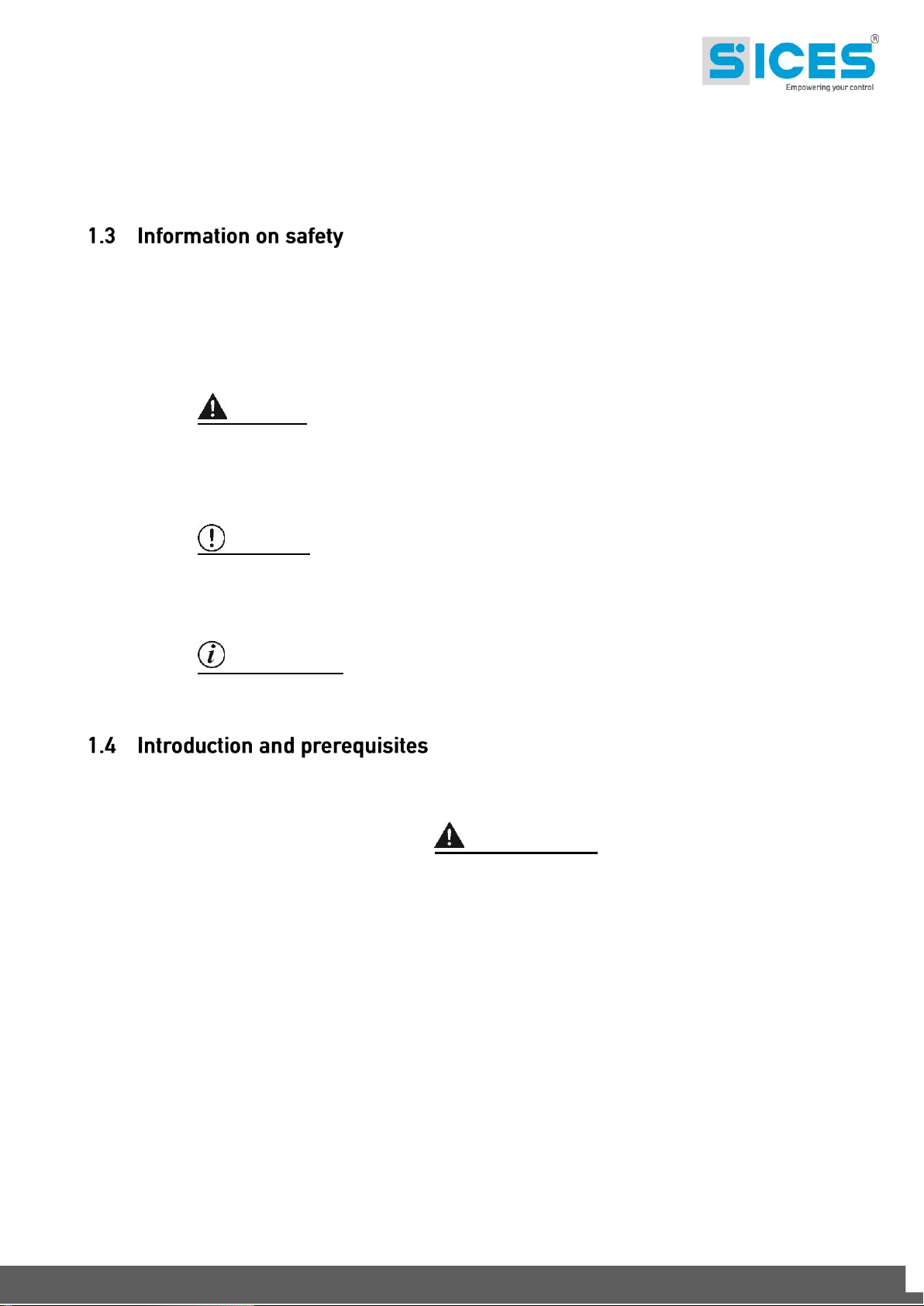
This manual contains the following indications:
CAUTION! This indication is used in the safety messages of the manual when there
are possible danger situations that may cause injuries or death if the danger is not
avoided.
This safety messages describe the normal precautions needed to avoid danger. Ignoring this
instructions may cause serious damages to things and/or people.
WARNING! This indication is used in the safety messages for dangers that, if not
avoided, may cause injuries, damages or malfunctioning.
The message can be also used only for few dangers that may cause damages to things and/or
people.
INFORMATION! This term indicates that the message includes useful information
for the development of the operation or procedures clarifications.
For the appropriate use of this manual it is required knowledge of the use and of the
installation of generator groups.
WARNING!!!
All interventions must be carried out only by qualified personnel, because dangerous voltages
are present on the terminals of the device; prior to performing any operation on the same,
make sure you have opened the circuit breakers and generator set switches, or that you have
removed their fuses.
Do not remove or modify any of the connections while the generator set is operating
Do not, for any reason, disconnect the terminals of the current transformers (CTs).
Incorrect interventions on the connections can result in disconnection of the users from the
mains or from the generator.
Before installing and using the device, carefully read this handbook.
The device uses a large number of configurable parameters and it is therefore
impossible to describe all their possible combinations and effects.
In this document it is not present a description detailed of all the programming parameters: to
this purpose see [1] [2]. These documents should be considered integral part of this manual.
The devices are supplied with a generic "default" configuration; is the responsibility of
the installer to adjust the operating parameters to his/her specific application.
GC315xx and GC400xx Technical Manual 17
SICES srl makes considerable efforts for a continuous improvement and upgrading of its own
products; therefore, they are subject to modifications both in hardware and software, without
prior notice. Some of the features described in this manual may therefore differ from those
present in your device.
IMPORTANT! Both the SW1 switches must remain in OFF position.
The SW1 switches are reserved for accessing special features that are not part of the normal
operation of the device.
If the device is powered with one of the two switches in ON position, it will not turn on.
To restore normal operation you need to cut the power to the same, turn the switches OFF
and power it again.
In case the device does not turn on when powered, the first thing you have to do is to check
the position of the switches.
Although most of the parameters and features can be accessed and configured by directly
operating on the device, some particular features or configurations, due to their nature,
can only be set or changed through the PC program SICES Board Programmer3
(hereinafter referred to as “BoardPrg3”) downloadable for free after registration on the SICES
srl websites www.sices.eu and www.sicesbrasil.com.br.
It greatly simplifies the configuration of the device and its use is strongly recommended. It also
allows you to save the current configuration of the device on a file and to reuse it on other
identical devices,
The program also allows the configuration, saving or loading of the characteristic curves of
non standard ANALOGUE sensors with resistive or live output.
BoardPrg3 can be used on all the SICES devices; connection to the PC can be realized both
directly, via the RS232 serial port, USB, or remotely via modem, RS485 serial port or ethernet
network. To use the program refer to document [3] .
In this document, the term “ALARM” is used to indicate a fault that prevents the generator set
from operating and causes the automatic emergency shutdown of the generator (skipping the
cool down phase).
The term “DE-ACTIVATION” is used to indicate a fault that prevents the generator set from
operating and causes the automatic standard shutdown of the generator (including the cool
down phase). The controller automatically opens the GCB circuit breaker in case of this type
of fault.
In this document, the term “” is used to indicate a fault that makes the genset operation
impossible, and causes the automatic shutdown of the genset with standard procedure.
The term “WARNING” is used to indicate a fault that requires the intervention of the operator
with no need for automatic shutoff of the generator (including the cool down phase). If possible,
GC400x controllers gradually reduce to zero the power supplied by the genset before opening
the GCB circuit breaker. This type of fault is available only for the GC400x controllers.
The codes that identify functions for input, output, status or other functions are preceded by
the following acronyms:
DIF (“Digital Input Function”): the following is a code for the configuration of the digital inputs.
DOF (“Digital Output Function”): the following is a code for the configuration of the digital
outputs.
18 GC315xx and GC400xx Technical Manual
AIF (“ANALOGUE Input Function”): the following is a code for the configuration of the
ANALOGUE inputs.
AOF (“ANALOGUE Output Function”): the following is a code for the configuration of the
ANALOGUE outputs.
AVF (“ANALOGUE Virtual Function”): the following is a code for the configuration of the virtual
ANALOGUE inputs.
EVT (“Event”): the following is an event code
ST (“Status”): the following code shows the status of a dimension or a condition of the device
or of one of its functions.
In this document a vertical bar on the right margin or a grey background indicates that the
chapter or the paragraph has been amended respect to the previous document’s version.
Changes in the fields of a table are highlighted with a grey background colour.
Several parts of this manual refer to the controller's software revisions. These revisions are
marked with the assigned SICES code (shown on the rear panel of the controller). Software
code version has the following format: EB0250231XXYY, where "XX" is the main revision
number and "YY" is the secondary revision number. Thus, the code EB02502310100 refers to
the controller's software release "1.00". The software revision is also displayed on page “S.06”
(GC315x) or “S.03” (GC400x) of the LCD display.
The software codes available at the release date are:
EB0250231xxyy: GC315.
EB0250248xxyy: GC400.
GC315xx and GC400xx Technical Manual 19
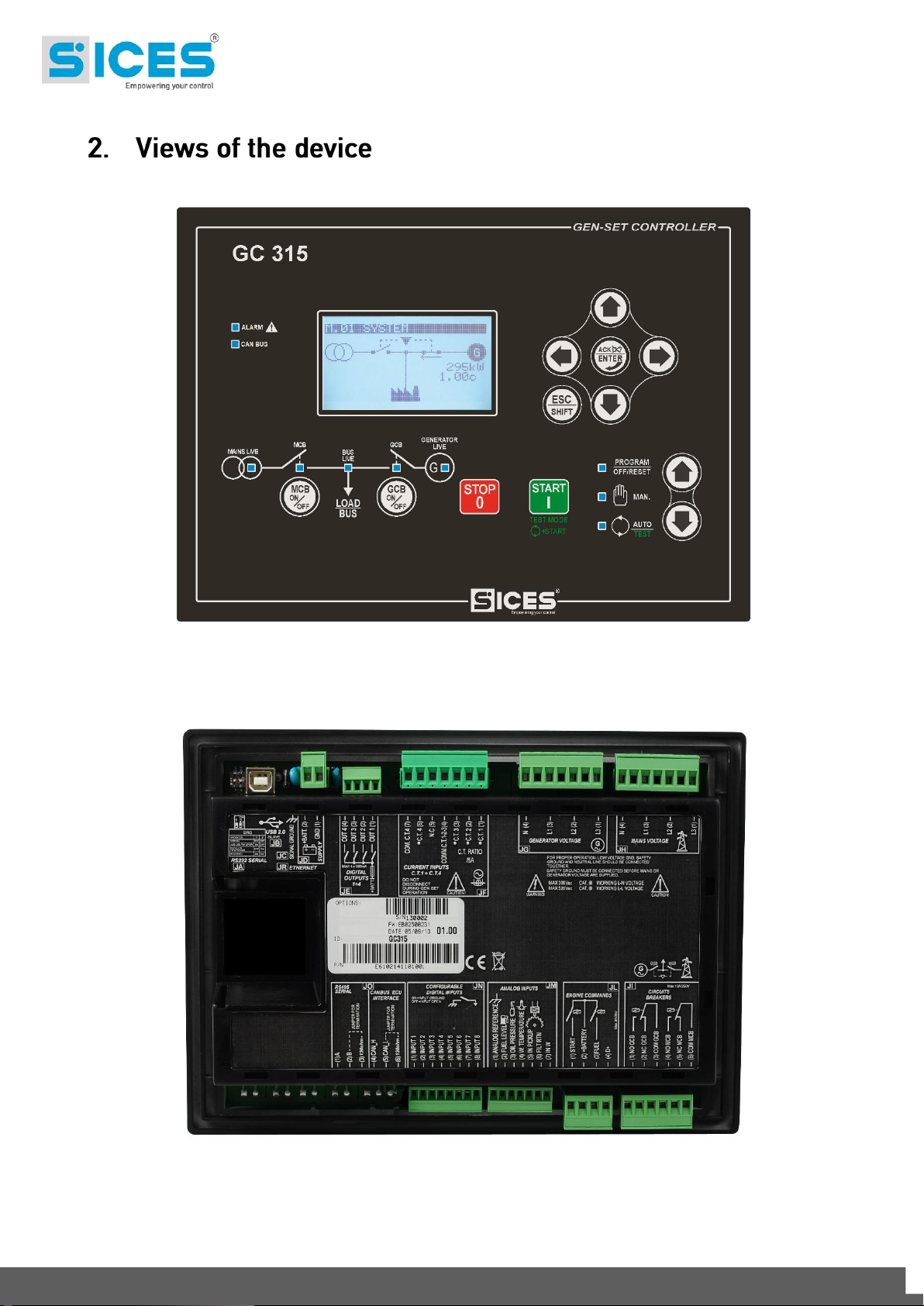
Front GC315
Back GC315
20 GC315xx and GC400xx Technical Manual
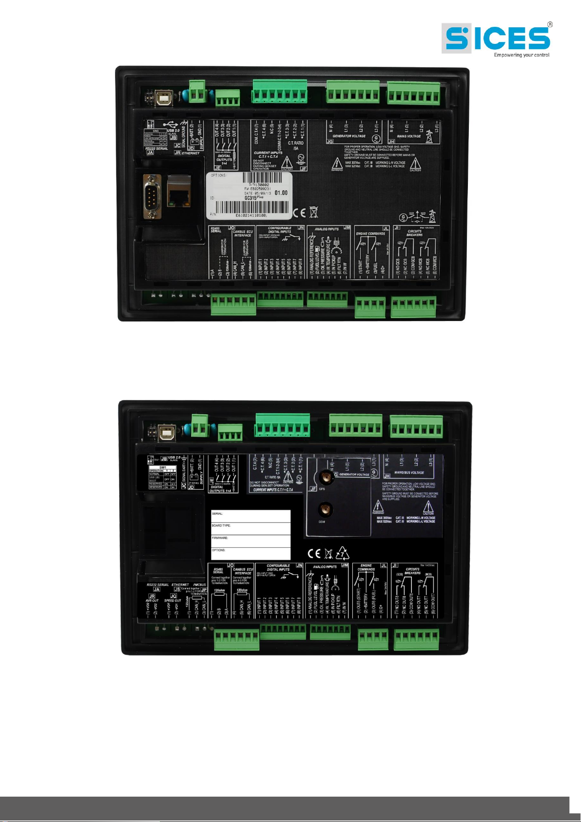
Back GC315
Plus
Back GC315
Link
GC315xx and GC400xx Technical Manual 21
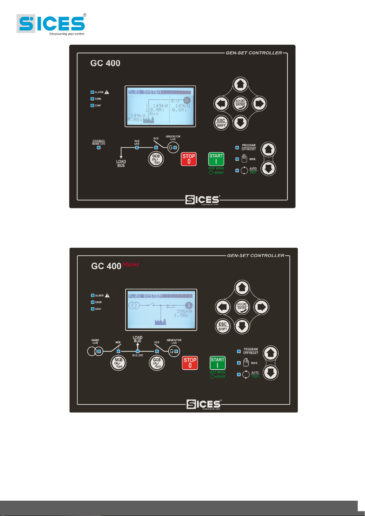
Front GC400x
Front GC400
Mains
22 GC315xx and GC400xx Technical Manual
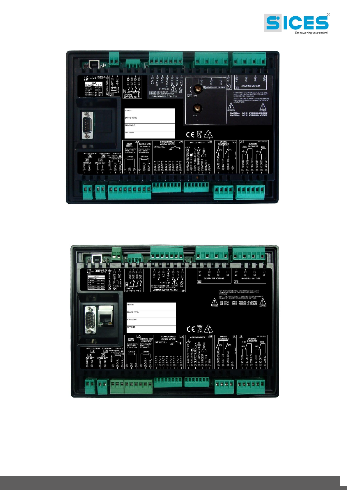
Back GC400 and GC400
Mains
Back GC400
Link
and GC400
Mains+Link
GC315xx and GC400xx Technical Manual 23

Supply power voltage
Vbatt:
GC315 and GC400:
7..32VDC with continuous operation.
GC315
Link
, GC400
Link
e GC400
Mains+Link
:
8..32VDC with continuous operation.
Protection against polarity reversal with built-in self-resetting fuse.
Operation during engine start is guaranteed up to Vbatt =5VDC indefinitely.
The device identifies the plant operation at 12 or 24V, to manage its alarms
when powered up and whenever OFF/RESET mode is selected.
Power consumption in
stand-by:
For GC315:
300mA @ Vbatt =13.5VDC display lamp on
280mA @ Vbatt =13.5VDC display lamp off
170mA @ Vbatt =27 VDC display lamp on
160mA @ Vbatt =27 VDC display lamp off
For GC400:
400mA @ Vbatt =13.5VDC display lamp on
310mA @ Vbatt =13.5VDC display lamp off
210mA @ Vbatt =27 VDC display lamp on
190mA @ Vbatt =27 VDC display lamp off
On the Link controller the consumption depend on the data exchange activity
with the Provider of the telephone service, on the quality of the connection and
the status of charge of the optional internal battery.
With battery out of power, the consumption is maximum; in stand-by:
GC315
Link
, GC400
Link
and GC400
Mains+Link:
about 650mA @ Vbatt=13.5VDC internal battery in charge
about 350mA @ Vbatt=27 VDC internal battery in charge
Maximum power
consumption in operating
condition (relays, alarm,
LCD lamp and digital
inputs enabled; static
outputs disabled)
For GC315:
Max 700mA @ 7 VDC
400mA @ 27 VDC
450mA @ 13.5 VDC
For GC400:
Max 800mA @ 7 VDC
430mA @ 27 VDC
480mA @ 13.5 VDC
On the Link controller the consumption depend on the data exchange activity
with the Provider of the telephone service, on the quality of the connection and
the status of charge of the optional internal battery.
With battery out of power, the consumption is maximum; in stand-by:
GC315
Link
and GC400
Link:
about 140mA @ Vbatt=8VDC
24 GC315xx and GC400xx Technical Manual

Electric measurements for
mains/generator set
voltage and currents:
ANALOGUE/digital conversion at 12bit; sampling frequency 10kHz. True RMS
measurements (TRMS).
Measurement of the L-N phase voltages and of the L-L concatenated voltages;
measurements of the neutral voltages referred to the power supply minus of the
device.
Input impedance of the voltage measurements:
>280kohm L-L
>270kohm L-GND
>210kohm N-GND
>150kohm L-L
Measurement of three currents with electrical return and C.T. report. In
common, plus a fourth independent current for Neutral current measurement or
differential protection or mains voltage measurement.
It is required the use of current transformers with a secondary current of 1 to 5A
(5A recommended) and minimum power of 1VA. It is mandatory to connect the
return poles of the current transformers to the supply minus of the device.
Maximum mains/generator
voltages allowed:
MAX 300Vac in CAT.IV for measures L-N
MAX 520Vac in CAT.IV for measures L-L
Maximum currents
allowed:
5Aac nominal values; possible sinusoidal transient voltage surges up to 20Aac
with progressive loss of the measurement accuracy depending on the amplitude
of the surge.
Frequency
measurements:
Nominal frequencies of 50 or 60Hz.
Obtained from the L1 phase voltage both for the mains and for the generator.
Mains frequency minimum sensitivity:
35Vrms L-N @ 50Hz
For the generator the sensitivity is decreasing with the frequency for the
recognition of the started engine and for greater disturbances rejection:
10Vrms L-N @ 5Hz
17Vrms L-N @ 50Hz
20Vrms L-N @ 50Hz
Digital inputs
8 digital inputs; GND supply minus activation. When opened, the voltage on the
input terminals is Vbatt.
Activation/deactivation threshold 2.5VDC
Typical current with closed contact:
6.5mA @ Vbatt= 13.5VDC
12mA @ Vbatt= 27VDC
Relay outputs:
Two relays with positive common input, max 3A @30VDC for starter motor and
fuel solenoid valve. Surge protection diodes incorporated.
The common plus also acts as input for the emergency stop. The voltage
measure at the common input is displayed on page S.14 of the display (EM-S)
Two relays with dry changeover contacts for remote control switching, max. 10A
@250Vac.
All the relay outputs can be reset regardless of the parameter.
SSR outputs
Four independent configurable outputs to battery plus, max 500 continuous mA
each; internal limitation to approximately 4A max. on transients <150us and
then thermal protection intervention. Protection against overload, short-circuit
and surge and integrated reverse polarity.
The output voltage is supplied through the positive supply terminal of the JD (2)
+BATT. device.
ANALOGUE ouputs (only
for GC400x)
Two insulated independent outputs (3kV insulation). The range goes from 10Vdc to +10Vdc. The resolution is 16bit (0,3 mV/bit).
Excitation output for
recharge alternator +D
Maximum current switched automatically, depending on the supply voltage
Vbatt:
200mA @ 13.5 VDC
100mA @ 27 VDC
If not used for the battery recharge alternator, you can configure the +D terminal
as ANALOGUE input, to acquire voltage measures ranging from 0 to 32V, or as
additional digital input with +Vbatt activation.
The voltage measure acquired is displayed in page S.15 of the display (D+)
Engine instruments
ANALOGUE inputs
Three inputs for resistive sensors plus one input for measuring and
compensation of the reference potential of their common minus.
Resistance measuring range:
rated 0..500 ohm with < 0.2% error
0..2k ohm with < 1% error
The three measurement inputs can also be used as digital inputs with GND
activation.
Voltage compensation range of the reference point:
-2.7..+5VDC
GC315xx and GC400xx Technical Manual 25

Pick-up input for engine
speed measurement
Filtered for DC currents blocking.
Minimum voltage 3Vac; maximum voltage 60Vac.
W input for engine speed
measurement
Use the pick-up input, with inner interference suppressor, to be inserted by
interconnecting pins 5 and 6 of the JM connector.
CANBUS Connection
Only GC315
Plus
and GC400:
CANBUS connection with insulation up to 1kV with SAE J1939 and MTU
protocols.
Only GC400:
Additional CANBUS connection with insulation up to 1kV with SICES protocol
PMCBus for the communication with other devices.
RS485 Connection
Only GC315
Plus
and GC400:
RS485 connection with insulation up to 1kV with MODBUS RTU protocol
Display
Graphic transflective LCD, size 70x38mm, resolution 128x64
Operating conditions
From -25°C to +60°C
GC315
Link
and GC400
Link
with internal battery charger:
From -25°C to +60°C
Size
247(L)x187(H)x40(P)mm
Weight
GC315 600g
GC315
Plus
620g
GC315
Link
650g with optional internal battery
GC400 650g
GC400
Link
750g with optional internal battery
GC400
Mains
650g
GC400
Mains/Link
750g with optional internal battery
Dimensions of the
mounting place
218x159mm
26 GC315xx and GC400xx Technical Manual
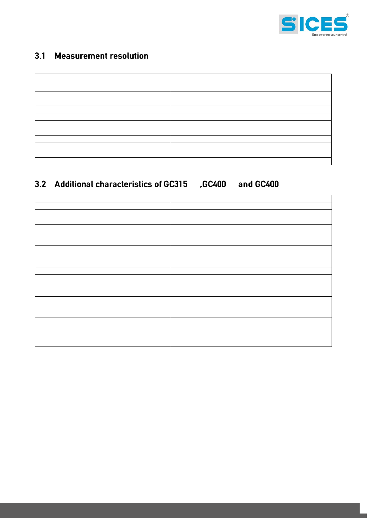
Mains voltages and generator
1Vrms
accuracy <0.5% F.S.
Current
Min. 0.1A (depends on the C.T.),
accuracy <0.2% F.S.
Mains frequencies and generator
0.1Hz ± 50ppm, 35ppm/C typical
Powers
Min. 0.1 kW/kVA/kvar (depends on the C.T. ratio)
Power Factor
0.01
Energy
1 kWh/kvarh
Engine speed
1 rpm
Oil pressure
0.1bar (below 10bar)
Coolant temperature
0.1°C
Fuel level
0.1%
Modem
Quad band 850/900/1800/1900 MHz
Modem operation
GSM/GPRS
Data transfer (GPRS)
Class 8/10, max download 85.6kbps
GPS Receiver
33 tracking/99 acquisition per channel
GPS Receiver perception
Tracking: -167 dBm
Reacquisition: -157 dBm
Cold starts: -148 dBm
First fix time
Cold start: 28s
Warm start: 26s
Hot start: <1s in ideal conditions
Accuracy
< 2.5m
Optional internal battery recharge
About 6h with complete unloaded battery; the time
depends also on the level of the GSM/GPRS signal and
on the data transmission interval
Internal battery duration
Minimum about 6h with SI.MO.NE data transmission
interval of 3 min and good signal level; it is higher using
the saving sleep-mode.
Antenna Impedance
GSM/GPRS 50 ohm
GPS 50 ohm; it requires an amplified antenna. The
alimentation is automatically supplied by the GPS
receiver.
Link Link Mains+Link
GC315xx and GC400xx Technical Manual 27

The device must be mounted permanently on an electrical panel or cabinet. The back of the
device must be accessed only through the use of keys or tools, and only by personnel
authorized to perform maintenance operations. The device must be mounted so as to make it
impossible to remove it without using tools.
The dimensions of the mounting slot are 250x159mm. The device is mounted with four hooks
with locking screws: once you have put the device in place, insert the hooks in the side slots
and tighten the screws. Be careful not to overtighten the screws to avoid damaging the
coupling slots on the casing of the device.
Due to high voltages associated to the measurement circuits of the controller, all the
conductive parts of the electrical panel must necessarily be connected to the protective
earth by means of permanent connections.
Installing an overcurrent protection device is required for each phase of the mains and
generator voltage inputs. 1A fuses can be conveniently used.
The conductor cross-section of the protective earth of the electrical panel must be at least
equal to the section of the wires used for wiring the mains or generator voltage to the panel.
In addition, it must comply with the limit value of the overcurrent protection used.
For CAT.III applications, the maximum phase-to-neutral voltage allowed is 300Vac, while the
phase-to-phase voltage is 520Vac. Maximum voltage with respect to the protective earth is
300Vac.
The device can operate in CAT.III only if the supply minus terminal of the device and the
neutral terminal of the generator are connected to the protective earth.
28 GC315xx and GC400xx Technical Manual
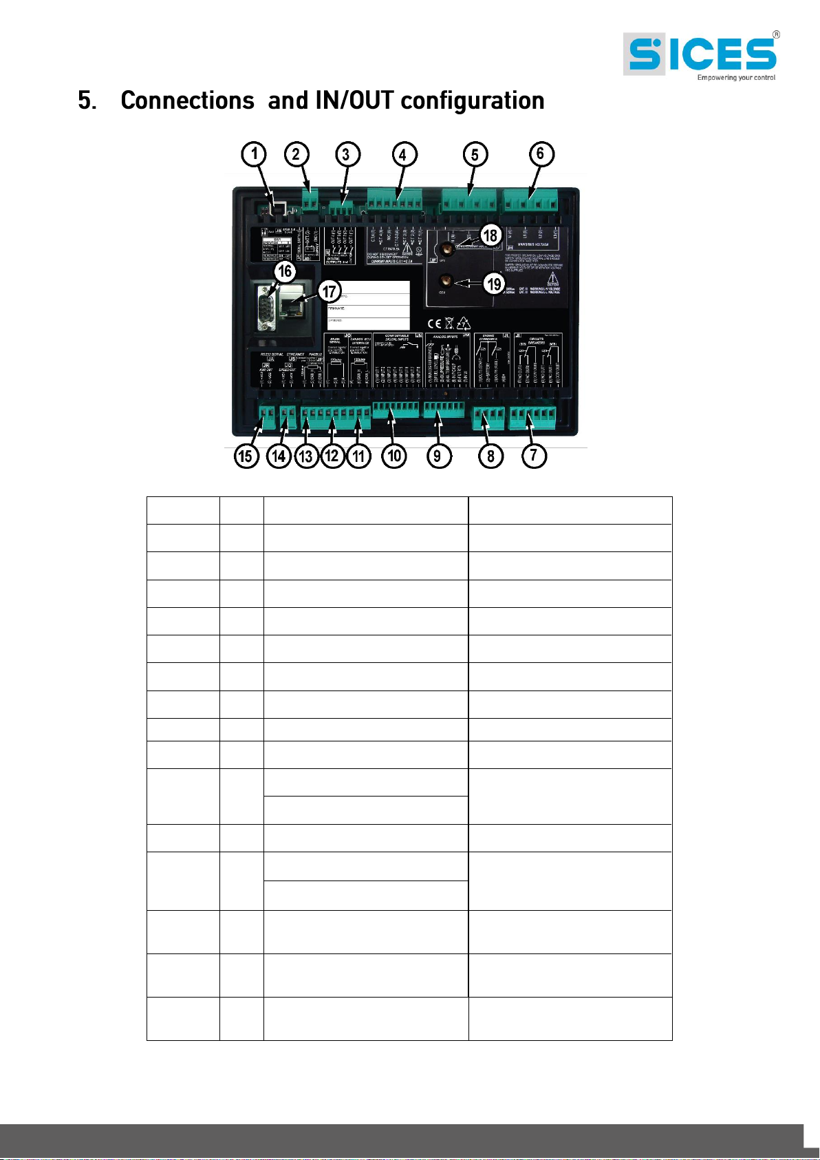
No.
NAME
DESCRIPTION
CONNECTOR
1
JA
Interface RS232 (Only GC315
Plus
)
9 Poles Male Canon
2
JB
USB
USB B
3
JD
Power supply
2 poles x2.5mm2 Screw terminal
3
JE
Auxiliary Outputs
4 poles x1.5mm2 Screw terminal
4
JF
Currents Input
7 poles x2.5mm2 Screw terminal
5
JG
Generator Voltages
4 poles x2.5mm2 Screw terminal
6
JH
Mains Voltages
4 poles x2.5mm2 Screw terminal
7
JI
Remote control switches
6 poles x2.5mm2 Screw terminal
8
JL
Engine commands
4 poles x2.5mm2 Screw terminal
10
JM
Pick-Up / W
7 poles x1.5mm 2 Screw terminal
Engine tools
11
JN
Digital inputs
8 poles x1.5mm 2 Screw terminal
12
JO
RS485 Interface (not available on
GC315)
3 poles x2.5mm2 Screw terminal
ECU Can-bus J1939 (not available
on GC315)
13
JP
PCMBUS Interface for parallel
functions (available only for
GC400x)
3 poles x2.5mm2 Screw terminal
14
JQ
ANALOGUE output for speed
regulator (available only for
GC400x)
3 poles x2.5mm2 Screw terminal
15
JR
ANALOGUE output for voltage
regulator (available only for
GC400x)
3 poles x2.5mm2 Screw terminal
GC315xx and GC400xx Technical Manual 29
16
JS
Ethernet (not available on GC315,
GC315
Link
, GC400
Link
and
GC400
Mains+Link
)
RJ45
17
GPS
GPS receiver interface (available
only for GC315
Link
and GC400
Link
)
1 SMA female connector
18
GSM
GSM Modem interface (available
only for GC315
Link
, GC400
Link
and
GC400
Mains+Link
)
1 SMA female connector
30 GC315xx and GC400xx Technical Manual
 Loading...