

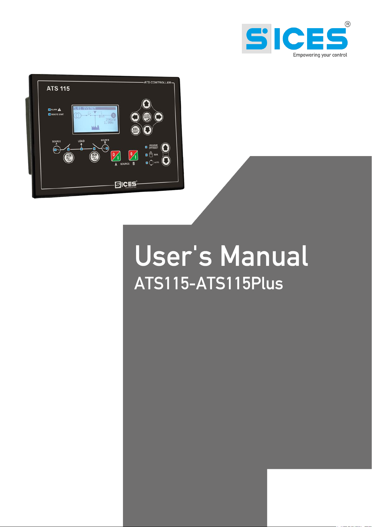
Sices ATS115, ATS115Plus User Manual
File Name: EAAM048102EN.docx
Rev. 02 Date: 26/09/2014
ID Document: EAAM030481
Product: ATS115-ATS115Plus
User’s Manual
1. Information on security ........................................................................................... 3
2. Information on the disposal .................................................................................... 3
3. Definitions ................................................................................................................ 4
.................................................................................................... 5
........................................................................................................... 7
........................................................................................................... 7
............................................................................................ 8
....................................................................................... 10
........................................................................................ 11
................................................................................................. 11
..................................................................................... 12
...................................................................... 12
.................................................................. 13
......................................................................... 13
...................................................................................................... 14
..................................................................................... 14
.............................................................................. 20
................................................................... 24
....................................................................................... 27
6. Working principle .................................................................................................. 28
............................................................................................................. 28
................................................................................................................ 29
........................................................................................................... 30
7. Special settings ..................................................................................................... 31
............................................................................................. 31
............................................................................................... 31
ii ATS115-ATS115Plus User’s Manual
This manual must be conserved with care and be always available for a rapid consultation.
It must be read carefully and understood in every paragraph by who will use and periodically maintain
the device.
If the manual is lost or damaged, ask the Technician/Manufacturer for a copy, by providing the model,
the code, the serial number and the year of construction of the device.
A lot of accidents are caused by unsufficient knowledge and by lack of security rules implementation to
comply with during the operations of working and/or maintenance.
In order to avoid accidents, before carrying out any working and/or maintenance operation, read,
understand and follow the indications and warnings contained in this manual.
The security messages contained in this manual are represented by the following indications:
WARNING! This indication is used in case of dangers that, if not avoided, may
cause malfunctioning to things or persons.
INFORMATION! This indication is used to provide useful information and
clarifications during an operation or procedure.
INFORMATION! Disposal of old electric and electronic devices (valid for the European
countries that implemented recycling systems).
Products having a crossed garbage wheelie bin cannot be disposed together with the normal
garbage. Old electric and electrical products must be recycled in a proper structure, able to
process these products and dispose their components. In order to know where and how to
send these products near you, please contact the proper municipal office. Right recycling and
disposal help to preserve nature and to prevent harmful effects to health and environment.
ATS115-ATS115Plus User’s Manual 3

STOP: it is used to indicate an anomaly that makes impossible the normal operation of the plant.
WARNING: it is used to indicate an anomaly that requires an operation intervention.
ACB (“A Circuit Breaker”): breaker or component for the management of the changeover between
Source A and the Load.
BCB (“B Circuit Breaker”): breaker or component for the management of the changeover between
Source B and the Load.
SOURCE A: it is used to indicate the genset or the mains connected on one side of the ACB.
SOURCE B: it is used to indicate the genset or the mains connected on one side of the BCB.
LOAD: loads electric supply. It can be connected whether to the Source A or to the Source B.
MAINS: public electric supply.
GENSET: electric supply connected to the genset alternator.
DIF (“Digital Input Function”): the code that follows is used to set the digital inputs.
DOF (“Digital Output Function”): the code that follows is used to set the digital outputs.
AIF (“Analogue Input Function”): the code that follows is used to set the analogue inputs.
4 ATS115-ATS115Plus User’s Manual
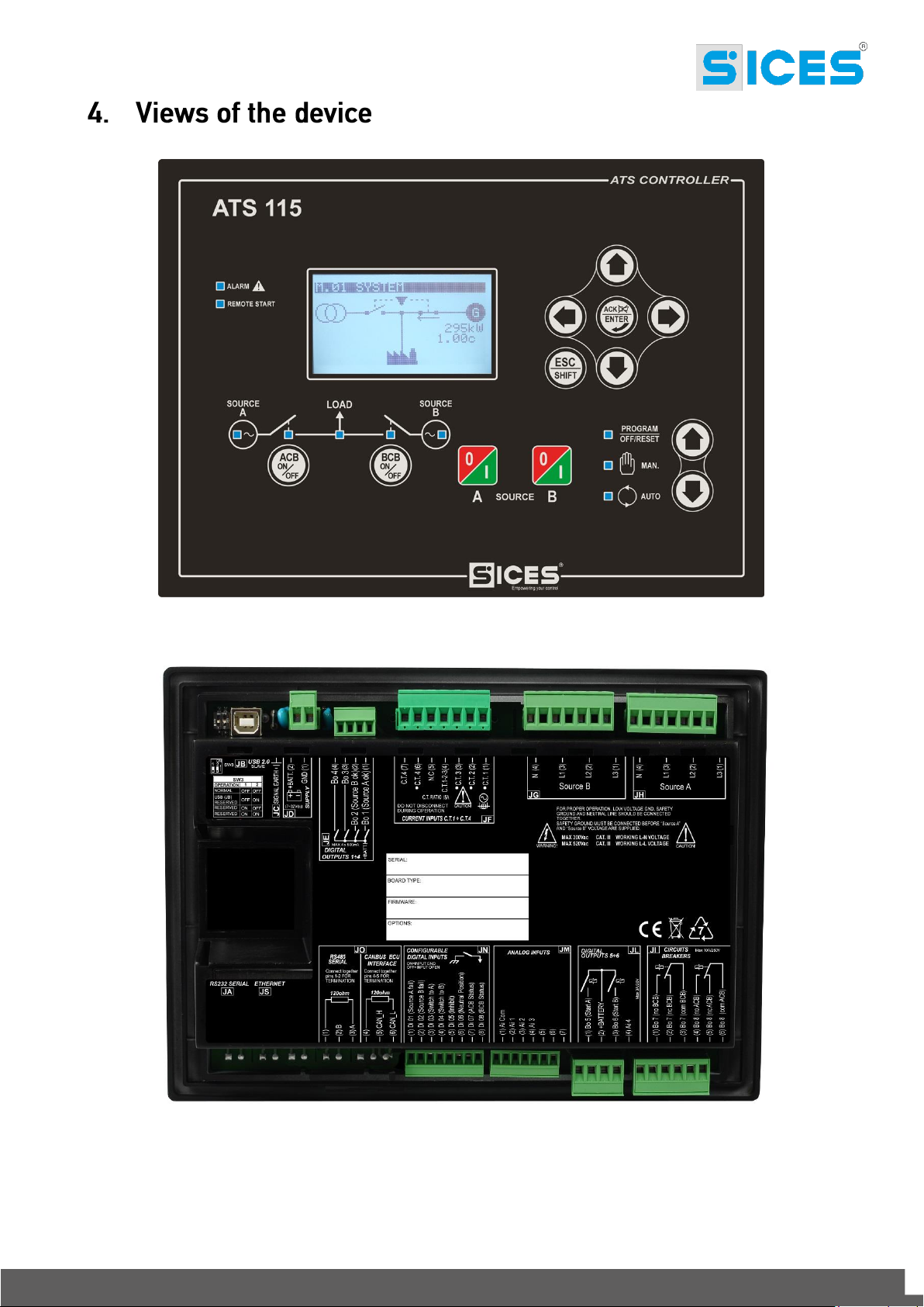
Fig. 1 ATS115-ATS115
Plus
Front View
Fig. 2 ATS115 Back View
ATS115-ATS115Plus User’s Manual 5
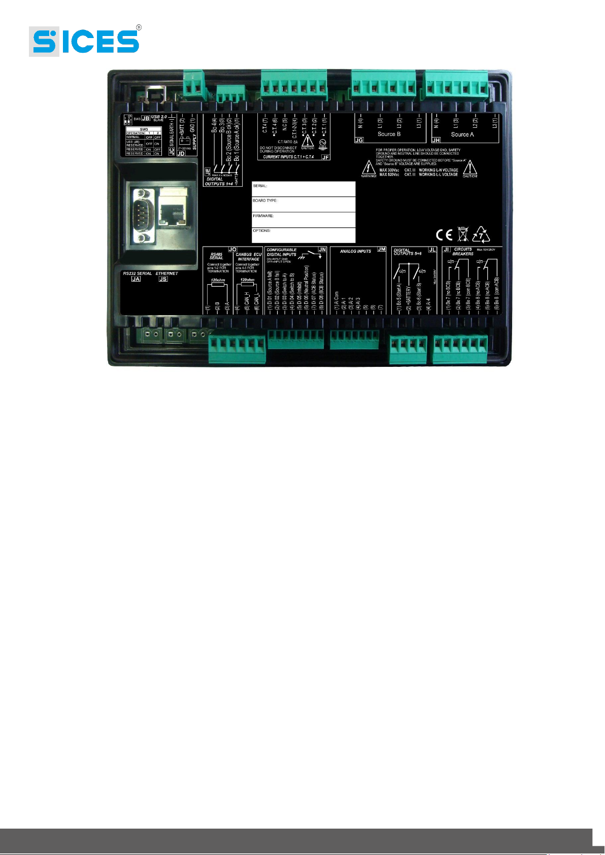
Fig. 3 ATS115
Plus
Black View
6 ATS115-ATS115Plus User’s Manual
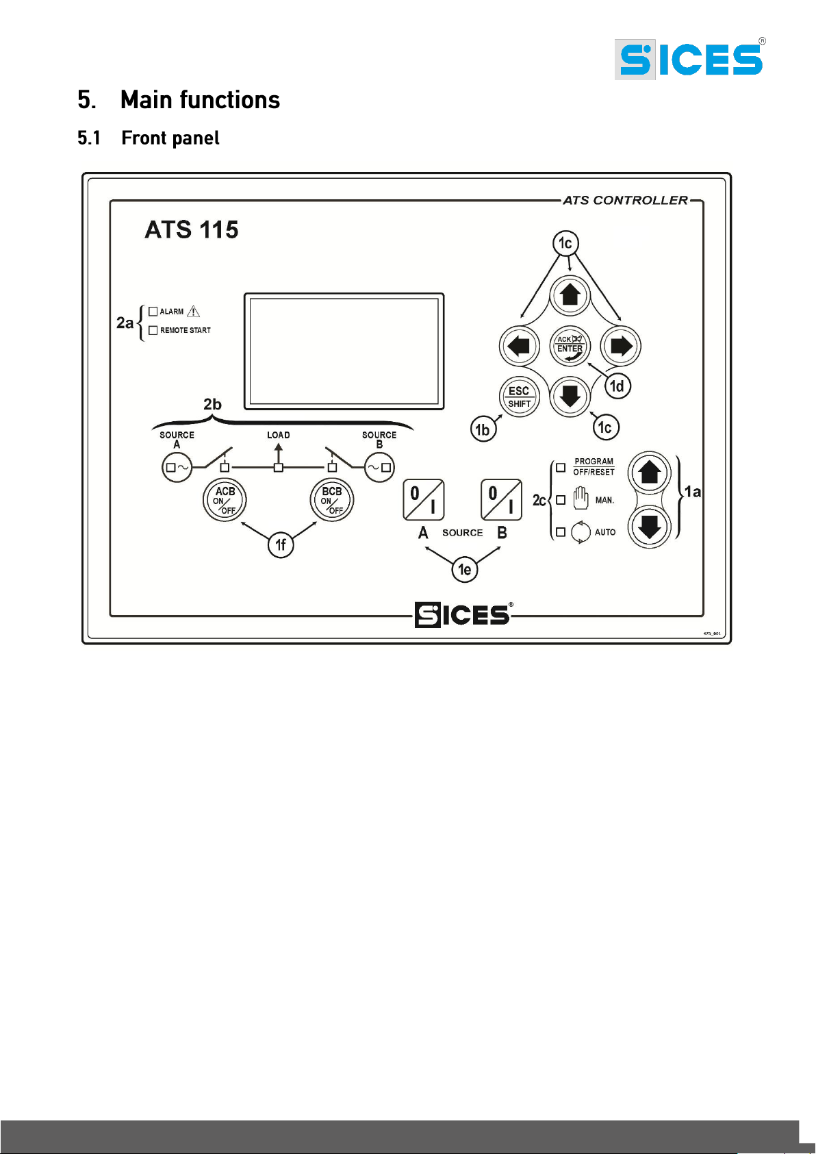
Fig. 1 –ATS115-ATS115
Plus
ATS115-ATS115
1 – Buttons
2 – Light indicators
The controls are made up of 12 buttons (1a, 1b, 1c, 1d, 1e, 1f).
In addition, on the front panel there are light indicators (2a, 2b, 2c).
Plus
KEY
Front Panel
ATS115-ATS115Plus User’s Manual 7
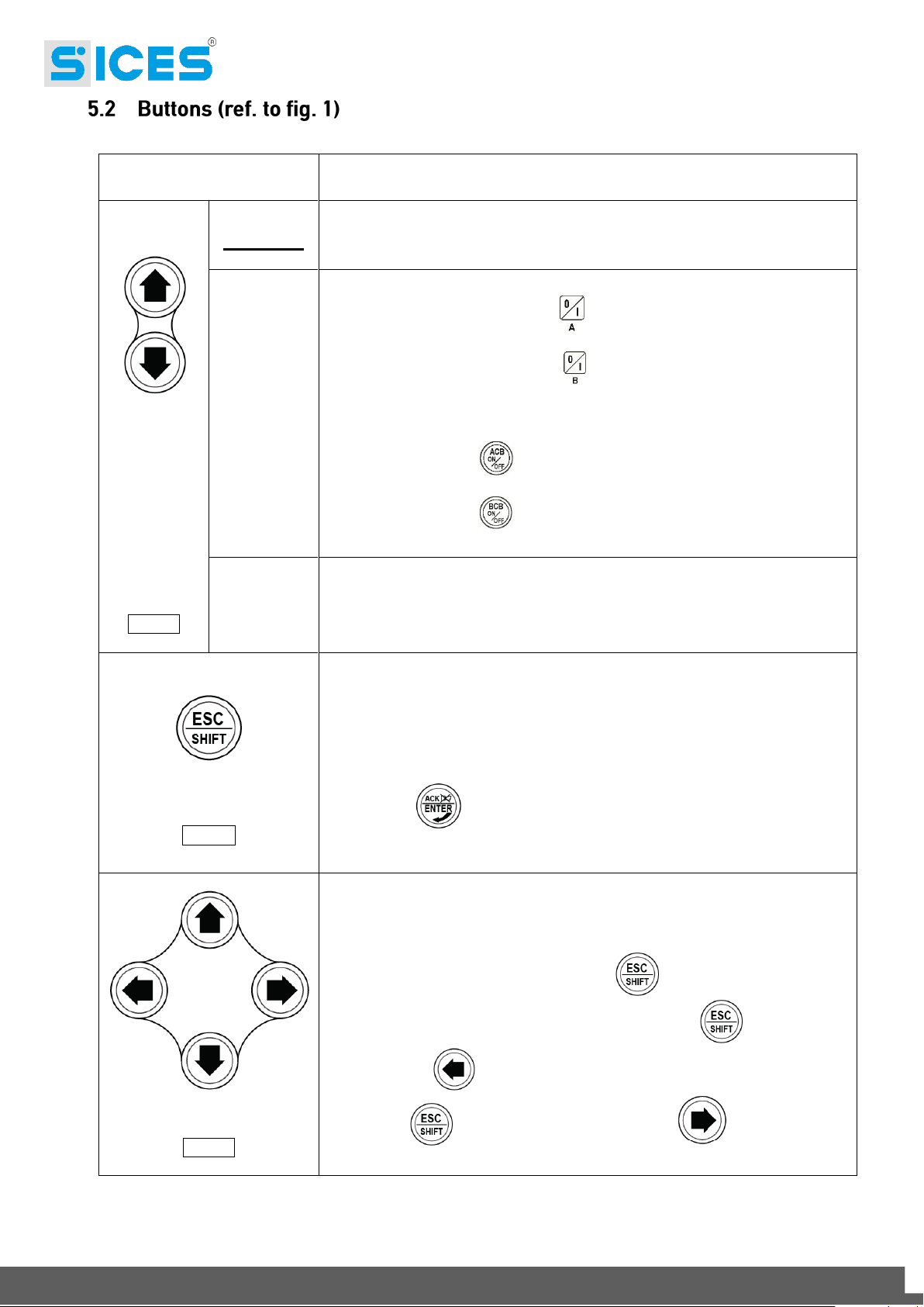
BUTTON
FUNCTION
MODE UP
MODE
DOWN
Ref. 1a
OFF/RESET
PROGRAM
The group is disabled; warnings and stops are cancelled. It is possible to
access to the parameters configuration.
MAN
(Manual)
The controller sets the genset manual operation.
Press the button START/STOP A to start/stop the Source A when it is
set as genset.
Press the button START/STOP B to start/stop the Source B when it is
set as genset.
With source live and in tolerance:
Press the button ACB for the manual opening/closing control of the
loads breaker/contactor on Source A.
Press the button BCB for the manual opening/closing control of the
loads breaker/contactor on Source B.
AUTO
(Automatic)
The controller sets the automatic changeover of the loads supply source and
intervenes in case of faults on one of the two sources.
Esc/SHIFT
Ref. 1b
In program mode, it allows to cancel a variable value change, come back to
the upper menu, and exit the programming. By pressing it for two seconds in
any of the menu, it allows to exit the programming saving the position for a
future return.
By pressing it for two seconds in any of the menu, it provides the engine status
in the upper line.
In OFF/RESET mode, according to the page selected, by pressing it together
with ENTER for at least 5 seconds, it can reset the counters, reload
the default values for the programming parameters or cancel the history log.
If used during the keyboard regulation functions, it aborts the function.
LEFT/RIGHT
Ref. 1c
The multifunctional display buttons allow to select the previous or next page
of display in all mode but PROGRAM. In the PROGRAM mode, they are used
to place the cursor during the strings insertion phase. The horizontal buttons,
combined with the button ESC/SHIFT , can adjust the contrast.
To reduce the contrast (lighten), press the ESC/SHIFT button together
with the LEFT button. To increase the contrast (darken), press the
ESC/SHIFT button together with the RIGHT button.
8 ATS115-ATS115Plus User’s Manual

BUTTON
FUNCTION
In PROGRAM and HISTORY LOG modes, it is possible to scroll the menus
and the variables/registrations. During the configuration, they allow to
increase/decrease the value of the variable. Using them together with the
button ESC/SHIFT , they allow to scroll the menus ten items at a time
or increase/decrease the value of the variable by ten units at a time.
ENTER/ACK
Ref. 1d
In PROGRAM, it allows to start programming and to enter in submenus, start
an operation of change of a variable or parameter and confirm said operation.
In HISTORY, it allows to start the HISTORY LOG and to enter in the selected
archive, to “accept” any possible fault warning on the non-volatile memory at
the start-up.
In case of alarm or warning, by pressing the button it acknowledges the
presence of a fault and stops the alarm. By pressing the button again, it resets
any possible warning if the operating conditions have come back as normal.
Interruption warnings can be set up again, only by activating the
“OFF/RESET” mode.
ACB
Ref. 1f
In “OFF/RESET” and “AUTO”, the button is disabled.
In “MAN”, it is used to open and/or close the contactor on the Source A to the
Load. The closing of the Load to the Source A it’s only possible if the related
electric measures are in the tolerance range.
BCB
Ref. 1f
In “OFF/RESET” and “AUTO”, the button is disabled.
In “MAN”, it is used to open and/or close the contactor on the Source B to the
Load. The closing of the Load to the Source B it’s only possible if the related
electric measures are in the tolerance range.
START / STOP
SOURCE A
Ref. 1e
In MAN mode, it can be used to control the start and stop of the source A
when it is configured as genset (if the Source A represents the Mains, it has
no effects).
At the controller power-up, pressing it together with the START/STOP B
button, it allows to access to special functions.
Pressing the button with the controller in OFF/RESET mode, it carries out the
LAMP TEST of all light indicators.
START / STOP
SOURCE B
Ref. 1e
In MAN mode, it can be used to control the start and stop of the source B
when it is configured as genset (if the Source B represents the Mains, it has
no effects).
At the controller power-up, pressing it together with the START/STOP A
button, it allows to access to special functions.
ATS115-ATS115Plus User’s Manual 9
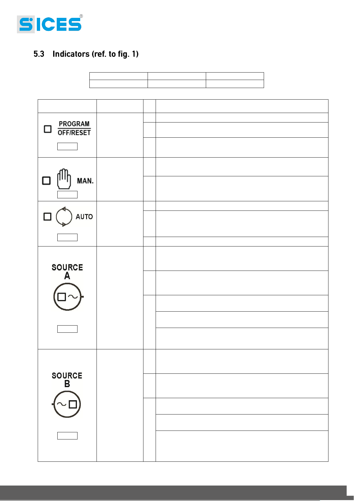
Led off
Led steady on
Led flashing
Warning
Function
Ref. 2c
PROGRAM
OFF/RESET
It states that the operation mode is OFF/RESET.
It states that you are accessing the PROGRAMMING menu.
The controller is in another operating mode.
Ref. 2c
MANUAL
It states that the operation mode is MANUAL.
The controller is in another operating mode.
Ref. 2c
AUTO
It states that the operation mode is AUTOMATIC.
Flashing at 90%, it specifies that the operating mode is
REMOTE START.
The controller is in another operating mode.
Ref. 2b
SOURCE A
LIVE
Source A voltage is present and steadily in tolerance.
The digital input EXTERNAL SENSOR SOURCE A is active
from the set time (DIF.3101).
Source A voltage is absent.
The digital input EXTERNAL SENSOR SOURCE A is inactive
(DIF.3101).
It flashes at 50% during the transition between the two previous
statuses.
Flashing at 25%, the mains voltage and frequency are on, but
below the tolerance range.
Flashing at 75%, the mains voltage and frequency are on, but
above the tolerance range.
Ref. 2b
SOURCE B
LIVE
Source B voltage is present and steadily in tolerance.
The digital input EXTERNAL SENSOR SOURCE B is active
from the set time (DIF.3102).
Source B voltage is absent.
The digital input EXTERNAL SENSOR SOURCE B is inactive
(DIF.3102).
It flashes at 50% during the transition between the two previous
statuses.
Flashing at 25%, the mains voltage and frequency are on, but
below the tolerance range.
Flashing at 75%, the mains voltage and frequency are on, but
above the tolerance range.
10 ATS115-ATS115Plus User’s Manual
 Loading...