

Sicce NINPHEO 25,NINPHEO 50 Instruction Manual

Via V. Emanuele115
36050 Pozzoleone (VI) ITALY
www.sicce.com
POND FILTER
TEICHFILTER
FILTRE POUR LE BASSIN
FILTRO PER L AGHETTI
FILTRO PARA ESTANQUE
VIJEVERFILTER
NINPHEO 25 - 50
INSTRUCTIONS
ANWEISUNGEN
INSTRUCTIONS
ISTRUZIONI
INSTRUCCIONES
INSTRUÇÕES
AANWIJZINGEN
ђуководств
EN
FILTER FOR ORNAMENTAL PONDS WITH UV-C STERILIZER SAFETY
RECOMMENDATIONS
To avoid damage to objects and/or personal injury the following safety r ecomme ndations
must be observed.
1) IMPORTANT: always unhook the power plug of this product and any other appliances in the pond before touching
the water,before any installation or maintenance work and even when the appliances are not in use.
2)
This product is weather resistant but not suitable for immersion.
If the appliance falls in the waterdo not attempt torecover it. Immediatelyunhook the power plug.
3) Ne ver use t h e pow er cabl e t o lift or move the ap pliance
4) This product is a filter with built-in UV-C sterilizer designed for use with ornamental ponds. It is not suitable for any
other use.
5) Do not use the appliancein ponds-pools or other situationswhere people are using the water.
6) Do not use the appliance if the power cable or plug are damaged. If the product is damaged it must be replaced by a
specialised aftersales centre.
7) Keep children away from this appliance.
8) Do not open the m etal V-band (10) or lift the filter dome (18) w hen the pump is working. This may cause a severe
hazard.
9) The electri cal sup ply mu st compl y with t he ele ctrical d ata plat e on th e produ ct.
10) If anextension lead is required, make sure it is waterproof.
11) The filter has a maxim um worki ng pre s s ure of 0.4 Bar .
12) Before installing the filter, check that t h e UV –C light bulb has not been da maged during transport. If this is the case
return the filter to the dealer a nd do not attempt to install it.
13) N ever look directly i nto and touch the UV-C lamp when it is on. This can harm eyes and skin.
14) This producthas been designedfor water at temperature up t o 35 C°
15) If the tem pe rature drops below 0°C un plug the power and complet ely em pty the fi lter. D uring the wint er it is better to
remov e the filt er and store i t in a s heltere d place.
16) D o not p osi tion t h e filter i n areas liable to floo ding or where it may risk f al ling in the water.
17) N ever operate the appliance withoutwater.
HOW THE NINPHEO FILTER WORKS
The range of Ninpheo filters has been designed to perform three important stages of filtration, essential i n maintaining
pond water clear and healthy:
Mechanical filtration obtained by special sponges that block all larger impurities or debris. Their variable porosity will
stop different sized particles.
Sterilisation by UV-C rays, this operation is allowed by the special UV-C lamp that is included in the filter. As the w ater
passes throughthe filter it is directed through a channel containing the lamp. This particular system can only be found
on Ninpheo filters and provides much greaterperformance than other filters.
The pump i n the pond feeds the filter with the water, thro ugh the inlet (A). The water then passes thr ough t he
mechanical filter compartment. A special header distributes the water uniformly over the sponges to ensure maximum
effici en cy over the whole surface area. At t his st a ge th e water reac he s the grille on t he bott o m of t he filter com p artment
and Bio-Ballswith the bacteria that eliminateany t oxic s ubstances. The water is now clean and passes through the UVC sterilizer that exploits the action of th e ultraviolet rays to inhibit alga growth. The water returns to the p ond through the
outlet (B).
FILTER INSTALLATION
The choice in positioning Ninpheo filter is very important.
• The filter can be placed at ground level, to give easy access to the drain plug under t he filter compartment for
emptyingthe filter. It canalso be partlyburied, however the V-band must be kept at l east 10 cm above ground level.
• Do n ot ever cover the filt er so t o avoid overhe ating.
• Place the filter on a flat,stable base, in an adequately ventilatedarea, shaded from direct sunlight.
• Locatet he filter at least one metre fromthe edge of the pond and make sure it cannot fallinto the water.
• Do n ot mak e the filt er worki ng at pressur es over 0.5 b ar. Nev er hook up the fi l ter to t he wat er mains.
Position thefilter so that the inlet (A) and outlet (B) hose couplings face the pond to avoid useless bends in the hoses
which can ca use furt her lo ss of w at er flow.
CONNECTING THE UV-C LAMP
Remove the pl ug from the fil t er dome (18) a nd ins er t t he glas s tube ( 16). Ma ke sur e t h at ther e is the suitabl e o-ring (12).
Insert t he UV-C lamp (15) i n the l am p hold er (17) and scr ew it in the fil t er dome.
CONNECTING THE HOSES
The Ninpheo filter requires two hoses that are not included. The first to connect the pump in the pond with the inlet
coupling(a), the second to return the cleanwater from the filter outlet back to the pond.
When installing the Ninpheo filter,it is importantthat the hose diameters are correctly sized. This will allow the pump to
obtain maximum water flow performance, avoiding bends i n the hoses that cause further loss of water flow. Always
fastent he hoses to the couplings with metal clamps(not supplied).
FILTER M AINTENANCE
CAUTION: Always unplug the filter from t he mains power before carrying out any maintenance
work.
• Do not ever openthe V-band( 10) beforehaving unplugged the pump and UV-C lamp.
• Aftert he filter has been unplugged,r emove the inlet and outlet hoses so they do not createa hindrance.
• The filtercan be emptied by removing the plug (3) on the bottom of the c ontainer.
• Remove the UV-C lamp (17) from the filter dome by unscrewing its cap. The filter dome must not be opened without
removi ng the UV-C l amp. This is highly recom mende d to a v oi d the risk of bre aki ng the glass bulb t h at prot ects the lamp
during handling.
• Open t he V band.( 10)
• Remove the filter dome (18) with special care paying attention to do not damage the OR gasket (8), w hich should be
washed and preferably lubricated with silicon grease before repositioning it.
• Removethe sponges(6), extracting them from thecentral hose and flush t hem out under running water.
• Loosen the screws on the bottomof the c ontainer (5) and remove the grille (4)on the bottom of the filter compartment
and rinse it out under running water.
• Completed these simple maintenance operations, assemble the filter following the abov e procedurein reverse order.
Make sure th e plug mount ed on t he centr al hose (9) is directed upwa rds (t ow ards t h e filter dome).
NINPHEO WITH B ACK-WASH FUN CTION
Position“Filter
” – Normal working position of t he filter.
Position“Recirculate
” – The water does not pass through the filtering material. It is only moved by the pump. This
function is very useful to do special disinfectant or other treatments in the pond as the pump keep in m ovement the
unfilter ed water.
Position“Back-Wash
”- Stop the pump disconnecting it from the electric circuit; put the handle on “backwash” position;
turn on t he pump and check that the water circulatesr egularly inside the system (the water must come out from the
backwash draining tube) (C); let the pump working until t he water is clear (1min.). Stop the pu mp again and p ut the
handle on“filter” position. R estart the pump.
Position“Winter
” – Recommended for the winter season. In this position the filter is compleately open and aired. In
any case, it is better to empty, clean and dry the filterand its componenets.D o not switch on the pump when the valve
is set on “Winter” position.
Position“Waste
” – Draining the water from the pond. This function must be activated when you want to empty the
water from the pond. With this function the water entry is put intocom munication with the backwash tube (connected to
a sum p pit) wi t hout p a ssing thr ough th e filter.
Position“Closed
” – Filter is closed. The water cannot go out.
Important:
The p ump m ust not abs olutely work. Lack of
water may cause irreparable damage to it.
Changing UV-C lamp
Replac ement UV-C l amps are s upplied co mplete with c ap and glas s b ulb. The light bulb alone c annot be replaced.
(Please, contact a sp ecialize d assistance c entre).
Winter shutdowns
The filter mu st be protected fr om frost. Duri ng the winter season the filter should be shut down, empti ed of all water,
removed and storedin a dry, sheltered place. It isbest to leave the filter open during storage.
Selecting the right Sicce pump and right N inpheo filter for your pond.
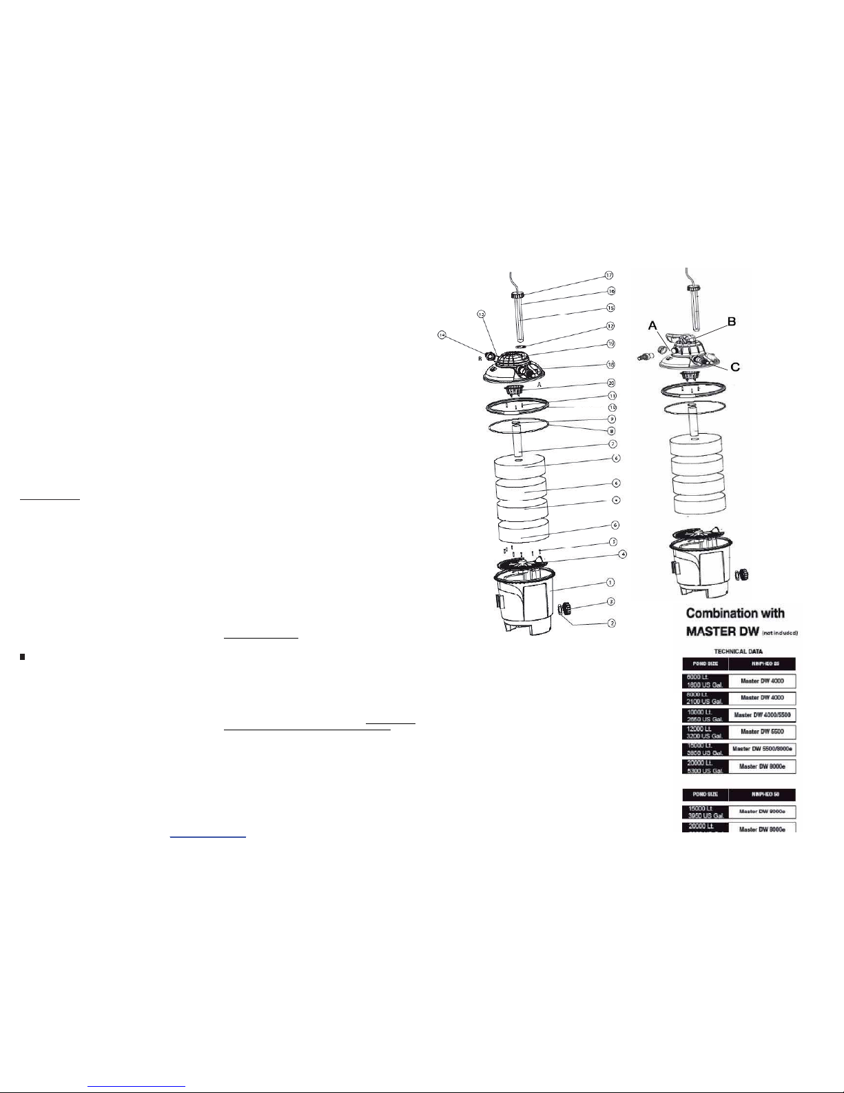
A table has been provided to select the right filter and pump combination for the size of the pond. This table is a
guidelineis based on measurements made by Sicce with a large scale oftest-customers and from laboratory analyses.
DE
FILTER FÜR GARTENTEICHE MIT UV-C-STERILISATOR HINWEISE ZUR
SICHERHEIT
Um jegliche Sach- und/oder Personenschäden zu vermeiden, müssen die unten angegebe nen
Sicherheitsnormen beachtet werden
.
1)
WICHTIG:
Stets den Netzstecker dieses Produkts und aller anderen im Gartenteich vorhandenen Geräte aus der
Steckdose ziehen, bevor die Hände ins Wasser getaucht w erden, irgendwelche I nstallierungs- und Wartu ngsarbeiten
ausgeführtwerden oder die Geräte nicht benutztw erden.
2)
Dieses Produkt widersteht den Witterungseinflüssen, aber es darf nicht eingetaucht werden
. Wenn das Gerät
ins Wasser fällt, nicht versuc hen, es herauszuholen. Sofort den Stecker aus der Steck dose ziehen.
3) D as G erät keinesfalls durch Ziehenam S peisekabel anheben oder verlagern.
4) Dieses Produkt ist ein Filter mit eingebautem UV-C-St erilisator, der nur in Gartenteichen eingesetzt w erden darf. Das
Produkt keinem anderen Gebrauch als dem vorgesehenen zuführen.
5) D as G erät nicht in Schwimmbecken oder sonstigen Einrichtungen, w o sich Personen im Wasser befinden, benutzen.
6) D as G erät nicht benutzen, wenn es Beschädigungen am Kabel oder am Stecker aufweist. Wenn sich das Produkt als
beschädigterweist, muss es von einem spezialisiertenKundendienst-Centerausgewechselt werden.
7) Kindern darf der Gebrauch diese s Geräts nicht gestatt et wer den.
8) Den Metallring (10) nicht öffnen und den Filterdeckel (18) nicht anheben, wenn die Pumpe in Betrieb ist. Di eser
Vorgangkannsichalssehrgefährlicherweisen.
9) Der elektrische Anschluss des Geräts muss die auf dem Typenschild des Produkts selbst angegebenen Daten
berücksichtigen.
10) Falls ein Verlängerungskabel benutzt werden muss, sicherstellen,dass dieses hermetisch dichti st.
11)
Der maximale Betriebsdruckbeträgt 0.4 Bar.
12) Vor der Installierung des Filters kontrollieren, dass die UV-C-Lampe währ en d des Transports nicht beschädigt
wurde. Sollte dies der Fall sein, d en Filter z u m Händler zurückbringen und nicht vers uchen, ih n zu installieren.
13) Keinesfalls in die UV-C-Lampe blicken oder b erühre n, w enn diese einges chaltet ist. Dies kann zu Augen- oder
Hautsc häden f ühren.
14) Dieses Pr odukt wurde für die Behandlung von Wasser mit einerTem peratur bis zu 35 C° konzipiert.
15) Wenn die Temperatur unter 0°C sinkt, die Stromversorgung abtrennen und den Filter v ollständig entleeren. Es ist
anzuraten,den Filter im Winter zu entfernen und an einem geschützten Ort unterzubringen.
16) Den Filter nicht an Orten mit Überflutungsgefahr oder in Positionen, die das Produkt ins W asser stürzen lassen
könnten,positionieren.
17)
Das Gerät keinesfalls ohne Wasser benutzen.
FUNKTIONSPRINZIPDES FILTERS NINPHEO
Die Filterreihe Ninpheo wurde ausgearbeitet, um drei wichtige Filtrationsfunktionen zu erfüllen, die von grundlegender
Wichtigkeit sind, um das W asser des Gartenteichsklar und gesund zu halten:
Mechanische Filtrierung
- realisiert durch Spezialschwämme, deren A ufgabe es ist, alle gröberen Verunreinigungen
zurückzuhalten. Di ese Schwämme weisen eine unterschiedliche Porosität auf, um P artikel unterschiedlicher Größe
aufhaltenzu können.
Sterilisation mittels UV-C-Strahlen
– Diese Funktion wird durch die speziellen, in der Lieferung enthaltenen UV-CLampen garantiert. Das gesamte Wasser ist während seines Flussverlaufs im Filter dazu gezwungen, einen Kanal zu
passieren, in dem diese Lampe vorhanden i st. Diese nur in den Filtern Ninpheo vorhandene Lösung garantiert eine
Leistung des Systems, die anderen Filtern ganz klar überlegen i st. Das Wasser erreicht den Filter über den Einlass (A),
der mit einer im Gartenteich vorhandenen P umpe verbunden ist. Anschließend wird das Wasser durch den
mechanischen Filtrationsabschnitt zwangsgeleitet. Die Homogenität der vollständigen Ausnutzung der
Schwammoberfläche wird durch eine spezielle Leitvorrichtung, die das Wasser auf den gesamten Schwamm verteilt,
gewährleistet. An diesem Punkt erreicht das Wasser das unten im Behälter befindliche Gitterund trifft auf die Bio-Balls,
wo d er Ko ntakt mit den B akterien erf olgt, die die d arin b efindlichen gi ftigen Substanzen zers etzen. Schließlich errei cht
das auf diese Weise gereinigte Wasser den UV-C-Sterilisator, der dank der Wirkung der ultravioletten Strahlen das
Wachstum von Algen hemmt.D as Wasser kehrt über den Auslass (B) in den Gartenteichzurück.
INSTALLIERUNG DESFILTERS
Es ist wichtig, einen geeigneten A uf stellungsort für den Fil t er Ninpheo zu f i nden, wobei sehr auf die folgenden Inf or m at i onen
geachtet werden muss:
• Der Filter kann am Boden aufliegend od er teilweise in die Erde eingelassen positioniert werden. Im ers t gen annten Fall hat
man die möglichkeit, den Filter zu entl eeren, nachdem die Pumpe abgetrennt wurde, dank des am Boden des Filterbechers
befindlichen Schraubstopfens. Im zweiten Fal l muss man darauf achten, dass der Metallring sich mindestens 10 cm über
dem Boden befindet.
• Der Filterkeinesfalls bedecken, um Überhitzungen zu vermeiden.
Cod. 80N135/A
FR
LÉGENDE (FIG. 1)ESLEYENDA (FIG 1)
1 Récipient filtre Contenedor del filtro
2 Garnitures d’étanchéité Empaquetad uras de estanco
3 Bouchon de vidange filtre Tapón de desca rga del filtro
4 Grille interne Rejilla interior
5 Éponges filtrantes Tornillos autorrosc antes
6 Joint torique tête filtre Esponjas filtr antes
7 Anneau métallique de fermeture Tubo central
8 Couvercle technique filtre Empaquet adura cabezal del filtro (O-
ring)
9 Tête filtre Tapón para tub oc entral
10 Lampe UV-C Anilla metálica de c ierre
11 Tube en verre contenant la lampe
UV-C
Tornillos autorrosc antes para difusor
12 Garniture pour éprouvette en vitre Empaquetad ura para tubo de vidri o
13 Garniture porte gomme (O-ring) Empaq uetadura boqui llas (O-ring)
14 Porte gomme 1”1⁄2 Boquillas 1”1⁄2
15 Lampe UV-C Lámpara UV-C
16 Eprouvette en vitre pour lampe UV-CTubo de cristal para lámpara U V-C
17 Porte lampe UV-C avec bagu e
filetée
Portalámpar aU V-C con virola filet eada
18 Couvercle technique filtre Tapa técnica del filtro
19 Tête filtre Cabeza del filtro
20 Diffuseur eau Difusor agua
EN – CAPTION (FIG 1) DE ERLÄUTERUNG (ABB. 1)
1 Filter compartment Filterbehälter
2 O-rings Dichtungen
3 Filter drain plug Filterauslassstopfen
4 Internal grille Inneres Gitter
5 Self-threading screws for grille Selbstschneidende Gitterschraube n
6 Filter sponges Filtrationsschwämme
7 Central hose Mittelrohr
8 Filter head gasket ( O-rin g) Dichtung Filterkopf (O-ring)
9 Plug for central hose Mittelrohr Verschlussring
10 Metal V-band Metallener Verschlussring
11 Self-threading screws for
diffuser
Selbstschneidende Schrauben für Diffuser
12 Glass tube gasket Reagenzglasdichtung
13 Hosetail gasket ( O-ring ) Gummihalterdichtung (O-ring)
14 1”1⁄2 hosetail Gummihalter 1“ 1⁄2
15 UV-C lamp UV-C-Lampe
16 Glass tube for UV-C lam p Reagenzglas für UV-C Lampe
17 UV-C lamp h older with
threaded ring nut
UV-C Lampenhalterung mit Gewinde
geschnittenerNutmutter
18 Technical filter dome Technischer Filterdeckel
19 Filter head Filterkopf
20 Water diffuser Wasserdiffuser
PT LEGENDA (FIG 1) RU УСЛОВНЫЕ (РИС.1)
1 Recipiente filtro
Коробка фильтра
2Guarnição
Уплотнительная прокладка
3 Tampa dedes carga dof iltro
Сливнаяпробка фильтра
4 Grelha interna
Внутренняярешетка
5 Parafuso para grelha
Самонарезающиевинты для решетки
6 Esponjas filtrantes
Фильтрующиегубки
7 Tubo central
Центральныйшланг
8 Guarnição da cabeç a do filtro (O-
ring)
Кольцевая уплотняющая прокладка
головки фильтра (Окол ьцо)
9 Tampa parao tubo central
Пробкацентрального шланга
10 Anél metálico de fechamento
Запорное металлическое ко льцо
11 Parafusos para difusor
Самонарезающиевинты для
распы лителя
12 Guarnição para proveta em vidro
Прокладкадля стекляннойпробирки
13 Guarnição porta borracha (O- ring)
Прокладкасоединительнойгайки (Окольц о)
14 Porta borracha 1 1⁄2
Соединительная гайка1”1⁄2
15 lâmpada UV-C
UV-C лампа
16 Proveta em vidro para lâmpada UV-CСтеклянная пробиркадля лампы UV-
C
17 Porta lâmpada UV-Cco mgrelha
Патрон UV-C с резьбовым зажимным
кольц ом
18 Tampa técnica do filtro
Техническая крышка фильтра
19 Cabeça do filtro
Головка фильтра
20 Difusor de água
Распылительводы
IT LEGENDA (FIG 1) NL LEGENDA (FIG. 1)
1 Contenitore filtro Filterhouder
2 Guarnizione di tenuta Afdichtingen
3 Tappo inferiore del filtro Afvoerdop
4 Griglia interna Binnenrooste r
5 Viti del contenitore/griglia Schroeven v oor rooster
6 Spugne filtranti Filtersponzen
7 Sede per tubo centrale Centrale b uis
8 Guarnizione di tenuta ( O-ring) Afdichting filt erkop (O-ring)
9 Tubo centrale Metalen sl uitring
10 Anello inmetallo Technisch filterdeksel
11 Viti Schroeven voor verspreider
12 Sede per lampada UVC Afdicht ing voor glazen r eageerbuisje
13 Guarnizione di tenuta ( O-ring ) Afdichting r ubberdrager (O- ring)
14 Guarnizione di tenuta Rubberdrager 1”1/ 2
15 Lampada UV-C UV-C lam p
16 Provetta in vetro Glazen reag eerbuisje voor lam p UV-C
17 Testa della pr ovetta per lampada
UV-C
Lampdrager UV -C met ring
18 Coperchio del filtro Technische fi lterdeksel
19 Testa del filtro Ko p filter
20 Tubodi fuoriu scitadell’a cqua Waterv erspreider
PDF created with pdfFactory trial version www.pdffactory.com
• Der Filter auf ein er ebenen, stabile n Basis a n einem au sreichend belüft eten und vor den UV -Strahl en der S onne
gesch ützten Ort positi onieren.
• Der Filter in einem Abstand von mindestens einem Meter vom Rand des Gartenteichs entfernt positionieren und
sicherstellen, dass er nicht ins Wasser fallen k ann.
• Der Fil ter nicht mi t einem Druck von mehr als 0.5 b ar betreiben. Der Filter keinesfalls an das Wass ernetz anschließen. Der
Filter so positioni eren, dass di e Anschlüsse des Ei nlas s- (A) und des A u slass rohrs (B) bereits zum G artent eich hin weisen,
damit vermi eden wird, dass die Anschlussrohre unnötige Krümmungen oder Biegungen anneh men müssen.
UV-C LAMPENANSCLUß
Verschlus s vom Filterdeckel (18) entfernen u nd das Reagenzglas ( 16) einfügen. S tellen Sie si cher, dass das O-ring (12)
vorhanden ist.
UV-C La mpe (15) in den L am penbehält er (17) ein setzen u nd diese m i t dem Fil terdeckel fest sc hrauben.
UV-C SCHLAUCHANSCLUß
Der Filter Ninpheo erfor dert die A nwendung von zwei biegsamen Rohre n, die nicht in der P ackung enthal ten si nd. D as
erste verbindet die i m Gartenteich befindlichePumpe mit dem Einlassanschluss (a), das zweite verbindet den Auslass
des Filters(sauberes Wasser) mit dem Gartenteichs elbst.
Es ist wichtig, dass während der Installierung des Filters Ni n pheo bie gsam e R ohre von geeignetem Durchmesser
ausgewählt werden. Auf diese Weise erhält man die maximale Pumpenleistung in Bezug auf die Wasserförderung.
Wenn möglich, Biegungen oder Krümmungen der Rohre meiden, um eine w eitere hydraulische Leistungssenkung zu
vermei den.
Stets sicherstellen, dass die Rohre mit Metallschellen (nicht beigefügt) an den Anschlüssen
befestigt we rden
.
WARTUNG DES FILTERS
ACHTUNG: Den Filter vor Ausführung irgendwelcher Wartungsarbeiten
stets von der elektrischen Netzleitungabtrennen
.
• Den Metallring(10) keinesfalls öffnen,bevor die Pumpe abgeschaltet und die UV-C-Lampe abgetrennt wurde.
• Sobald der Filter von der elektrischen Netzleitung abgetrennt wurde, wird empfohlen, das Einlass- und das
Auslassrohrdes Wassers abzunehmen, um ohne Hindernisse arbeitenzu können.
• Es ist möglich den Filter zu leeren, i ndem man den V erschluss (3) vom Behälterbodenentfernt.
• Die UV-C-Lampe (17) vom Filterdeckel nehmen, indem die entsprechende Zwinge aufgeschraubt wird. Dieser Vorgang ist
zum Öffnen des Filterde ck els zwin g end erfor derli ch, und wird empfohle n, um den Bruch des Glases, das die Lampe
beinhaltet, zu vermeiden (aufgrund eines unbeabsichtigtenKontakts mit irgendeinem Körper).
• Den metallenen Dichtungsring (10) öffnen.
• Den Filterdeckel (18) entfernen, wobei auf die Dichtung (8) geachtet werden muss. Diese muss für die anschließende
Benutzung gewaschen und möglichst geschmiert werden (nur Silikonfett).
• Die Schwämme (6) entfernen,indem man sie vom Mittelrohr herausnimmt, und unter fließendem Wasser abspülen.
• Schrauben vomB ehälterboden (5) entfernen, das Gitter (4) entnehmen und gut unter fließendem Wasser abspülen.
• Nach diesen Eingriffen den Filter wieder montieren, wobei die oben beschriebenen Arbeitsvorgänge in umgekehrter
Reihenfolge ausgeführt werden. Achten Sie darauf, dass der im Mittelrohr (9) eingefügte Verschluss nach oben gerichtet ist
(in Richtung des Filterdeckels).
NINPHEO BACK-W ASH FUNKTION
Position“Filter
” – Nor maler B etrieb
Position“By-Pass
” – Der Filter ist in R uhestellung, d.h., dass das Wasser wird nur bei der Pumpe berührt aber nicht
bei der Filtergereignet, weil der Durchlaufgeschlossen ist.
Position“Back-Wash
”- Die Pumpe ausstecken; mit ausgeschalteter Pumpe am Ventil die Position Rückspülen
einstellen, dann die Pumpe so lange wi eder einschalten, bis klares, sauberes Wasser aus dem Schlauch fließt (C). Die
Pumpe wieder ausschaltenund das Ventil in Stellung „N achspülen” oder “Filtern” bringen.Nun die P umpe f ür 1 Minute
laufenlassen.
Position“Winter
” – Position für Winter. Die Pumpe mit sauberem Wasser spülen und dann alles abtrocken. In der
Stellung „Winter“ sind alle Ausgänge des Filters geöffnet.In dieser Stellung darf also die P um pe niemals eingeschaltet
werden.
Position“Waste
” – Entleerung des Teichs. Man benutzt diese Funktion zum Entleeren des Teichs. Das Wasser wird
direkt, über den Schlauch fürR ückspülung (der in einen A bwasserkanal geleitet wird) hinausgepumpt, ohne durch den
Filter zu lauf en.
Position“Close
” – Der Filter ist geschlossen. Da s Wasser kann nicht aus dem Filter fließen.
Auswechseln der U V-C-Lampe
Die UV-C-Lampe wird von der Firma Sicce komplett mit Zwinge und Glasrohr geliefert. Es ist nicht möglich, nur die
Lichtquelle auszuwechseln(setzen Sie sich mit einen autorisiertenServicecenter in V erbindung).
Winterzeit
Der Filter muss vor Frost geschützt werden. Während der Winterzeit wird das Gerät ausgeschaltet. Das gesamte im Filter
vorhandene Wasser entfernen, den Filter abnehmen und an einem geschützten und trockenen Ort aufbew ahren. Es wi rd
empfohlen, den Filter während der Lagerung offen zu lassen.
Wahl der richtigen Sicce- Pu mpe und des richtigen N inp heo- Filters f ür I hren Gartenteich
Es wird eine Tabelle z ur Verfügung gestellt, mittels der die richtige Kombination Filter / Pumpe im V erhältnis zu den
Abmes sungen des Gart enteic hs er mittelt wer den kann. Dies e Wert e sind rein indikativ und wurden auf der Basis von
Daten, die von der Firma Sicc e bei einem stic hprobenweise durchgeführt en Customer-test ermittelt wurden, und
Laboranalysenvon Wasserproben aus den getesteten Gartenteichen ausgearbeitet.
FR
FILTRE POUR BASSINS D’AGRÉMENT AVEC STÉRILISATEUR UV-C CONSIGNES
DE SÉCURITÉ
Afin d’éviter tout dommage aux choses et/ou aux personnes, il est bon de respecter les normes
de sécurité énumérées ci-après
.
1)
IMPORTANT:
déconnecter toujours la fiche d’alimentation de ce produit et de tous les autres appareils présents
dans l e bassin avant de mettrel es mains dans l’eau, avant toute intervention d’installation ou de maintenance et même
quand les produits ne sont pas utilisés.
2) C e produit est résistant a ux agents atmosphériques mais n’ est pas s ubmersi ble. Si l’appareil to mbe dans l’eau, ne
pas t enter de le récupérer. Débrancherimmédiatement la prise de courant.
3) Ne j amais souleve r ou d éplacer l’appar eil en ti r a nt sur le câbl e d’alim entatio n.
4) C e produit est un filtre avec stérilisateur UV-C intégré à utiliser seulement dans les bassins d’agrément. Ne pas
utiliser ce produit pour des em plois différents de celui qui est prévu.
5) N e pas employerl’appareil dans des piscines ou autresenvironnements quand il y a quelqu’un dans l’eau.
6) Ne pas utiliser l’appareil si le câble ou la fiche sont endommagés. Si l e produit présente des dommages, il doit être
remplacé paruncentredeserviceaprès-ventespécialisé.
7) Ne pas permettre a ux enfants d’utiliser cet appareil.
8) Ne pas ouvrir l’anneau en métal (10) et ne pas soulever le couvercle du filtre (18) quand la pompe est en marche.
Cette opérationpeut se révéler très dangereuse.
9) La connexion électrique de l’appareil doit respecter les données figurant sur l’étiquette des données électriques du
produit.
10) S’il est nécessaire d’utiliser une rallonge, contrôler qu’elleest étanche.
11) La pression maximu m de ser vi c e du filtr e est de 0,4 Bar.
12) A v a nt de procéder à l’installation d u filtre, contrôler que la lampe U V-C n’a p as été endommagée au cours du
transport.Si elle présente des dommages, r apporter le filtre au négociantet ne past enter de l’installer.
13) Ne jamais regarder ni toucher la lampe UV-C quand elle est allumée. Cela peut provoquer des lésions oculaires ou
cutanées.
14) C e produi t a été projet é pour tr aiter l’eau à u ne tem pér ature jusqu’à 35 C°
15) Si la température descend au-dessous de 0°C débrancher l’alimentation et vider complètement le filtre. En hiver,il
est bo n de démont er le filt r e et d e le rang er dans un en droit à l’abri du gel.
16) Ne pas placer le filtredans des endroits sujets à inondation ou dans des positions où le produit risquerait de tomber
dans ’ eau.
17) Ne jamais utiliser l’appareil sans e au.
PRINCIPE DEFONCTIONNEMENT DU FILTRE NINPHEO
La gamme de filtres Ninpheo a été projetée pour réaliser trois fonctions im portantes de filtration, essentielles pour
maintenir l’eau du bassin limpide et sain :
Filtration mécanique
, réalisée avec des éponges particulières qui ont pour fonction d’arrêter les impuretés les plus
grossières. Ces éponges ont une porosité variable pour permettre de bloquerles particules de dimensions différentes.
Stérilisation par rayons UV-C
, cette fo nction est garantie par les lam pes UV-C spécial es incluses dans le filtre.
Dans son parcours à traversle filtre, l’eau est obligée de passer dans un canal contenant cettelampe ; cette solution,
présente uniquement dans les filtres Ninpheo, garantit un rendement du système nettement supérieur à d’autres
filtres.
L’eau arrive au filtre à travers l’entrée (A) reliée à une pompe située dans le bassin, puis l’eau est forcée à travers la
section de filtration mécanique. L’homogénéité de l’utilisation co mplète de la surface filtrante est garantie par un
dispositif spécial d’amenée qui distribuel’eau sur t oute l’éponge. À ce point,l’eau atteint la grille située sur le fond du
récipient et arrive aux Bio-Balls où elle entre en contact avec les bactéries qui décomposentl es substances toxiques
qui s’y trouvent. L’eau ainsi traitée p as se à travers le stérilisateur UV- C qui grâce à l’action de rayons ultraviolets,
empêchel a croissance d’algues.
L’eaurevientvers le bassin à traversla sortie(B).
INSTALLATION DU FILTRE
Il est important de choisir un emplacement adéquat pour le filtre Ninpheo en faisant très attention aux informations
suivant es :
• Il est possible de situer le filtre sur le sol ou partiellement enterré. Dans l e premier cas, on a la possibilité de vider le
filtre après avoir séparé la pompe, grâce au bouchon vissé sur le fond du récipient du filtre. D ans le deuxième cas, il
faut faireattention à ce que l’anneau en métal se trouveau m oins 10 cm hors du sol.
• Ne jamais couvrirle filtre pour éviterles s urchauffes
• Situerle filtre sur une base plate et stable,dans un endroitsuffisamment aéré et à l’abri des r ayons UV du soleil.
• Situerle filtre à pas moins d’un mètre du bord du bassin et s’assurer qu’il ne peut pas tomber dans l’eau.
• Ne pas faire fonctionnerle filtre à des pressions supérieures à 0,5 bar. Ne jamais raccorderle filtre au service d’eau
Situer le filtr e de manière que l es racc ords du tuyau d’entrée (A) et de sortie (B) s oient d éjà ori e ntés v er s le b assin d e
manière à éviter que les tuyaux de raccords présentent des courbes ou des coudes inutiles. Éviter que les tuyaux de
raccordsprésente des courbes ou des coudes inutiles.
CONNEXION DE LA LAMPE UV-C
Enlever le bouchon du c ouvercle du filtre (18) et insérer l’éprouvette en vitre ( 16) en contrôlant que l’O-ring soit
présent(12).
Insérerla lampe UV-C (15) dans la porte lampe (17) et visser ce dernierdans le couvercledu filtre.
RACCORDEMENT DES TUYAUX
Le filtre Ninpheo demande l’utilisation de deux tuyaux flex qui ne sont pas co m pris dans l’emballage. Le premier
raccorde la pompe située dans l e bassin avec le raccord d’entrée (a), le deuxième raccorde la sortie du filtre (eau
propre)avec le bassin.
Lors de l’installation du filtre Ninph eo, il est important de choisir les t uyaux flexibles d’un di amètre adéquat. De cette
manière, on obtientle rendement maximum de la pompe en termes de débit d’eau et, si possible, on évitel es coudes
et les courbes des tuyaux qui peuvent causer une ultérieureperte du charge hydraulique.
Contrôler toujours que les tuyaux sont solidement fixés aux raccords avec des colliers métalliques
(ne pas
fournis en dot ation).
MAINTENANCE DUFILTRE
ATTENTION
: Débrancher toujours le filtredu secteur électrique avant toute opérationde maintenance.
• Ne jamais ouvrirl’anneau en métal (10) avant d’avoir détaché la pompe et déconnecté la lampe UV-C.
• Après avoir débranché le filtre du secteur électrique, il est conseillé d’enlever les tuyaux d’entrée et de sortie de
l’eau pour pouvoir travailler sans aucu n o bst acle.
• Il est possible de drainer le filtreen enlevant le bouchon (3) posé au fond du récipient.
• Enlever la lampe UV-C (17) du couvercle du filtre en dévissant la bague. Cette opération c’est indispensable pour
ouvrir le couver cle du fi ltre, pour éviter de casser le verre qui entoure la lam pe (suite au contact acci dentel avec un
corps contondant).
• Ouvrirl’anneau d’étanchéité métallique ( 10).
• Enlever le couver cle du filtre (18) en faisant attention à la g arniture d’étanchéité (8). Cell e-ci doit être l avé et si
possiblegraissée (uniquement avec une graissesilicone) p our l’utilisation succ essive.
• Enleverl es éponges (6) en les ôtant du tuyau central et lesl aver à l’eau courante.
• Dévisser les vis au fond du r écipient (5) et enlever la grille (4), bien la laver à l’eau courante.
• Après avoir fait c es interventions, remonter le filtre en suivant les opérations décrites ci-dessus dans le sens inverse
en faisant attention que le bouchon inséré dans le t uyau central (9) soit orienté vers le haut (vers le couvercle du
filtre).
NINPHEO AVEC FUNCTION“BACK-WASH”
Position“Filtration
” – Position de marche normal du Filtre.
Position“Récirculation
” – L’eau ne passé pas dans le filtre et son matériau de filtration mais elle est simplement
pouss ée par la po m pe. C et t e fonctio n est tr ès uti le pour désinf e station spécif i q ue ou autres traite m e nts du bassi n car la
pompe maintientl’eau non filtrée en mouvement constant.
Position“Back-Wash
”- Arrêter la pompe, la débrancher du réseau d’alimentations électriques; quand la pompe est
éteinte, placer l a Vane de sél ection sur la positio n contre lavage et metre en route la pompe jusqu’à ce que l’eau qui
sorte du tuyau soit propre (C). Refermer la pompe et placer la vanne de sélection sur “rinçage” ou “filtrage”.Remettre
en route la pom pe.
Position“Winter
” – Recommandé pour l’hiver. Dans cette position le filtre est complémentouvert et l’airé. En tout cas,
il vaut mieux vidanger, nettoyer et essuyerle filtreet ses composants et le conserver dans un lieu sec. Ne pas metre en
marche la pompe quandl a vanne est en position “Winter” (Hiver).
Position“Egout
” – Evacuation de l’eau de la piscine. C ette fonction doit être activé quand on veut vider de la piscine.
De cette façon, on met en communication l’entrée de l’eau avec le t uyau de contre lavage (branché à une bouche
d’égout)sans passer par le filtre.
Position“Closed
” – Le filtre est fermée. L’eau ne passe pas et ne peut pas sortir.
Important:
La pompe ne doit
absolument pa s entre en fon ction. L’abse nce d’eau peut causer des dommages irré parables alla pompe.
Remplacement de lalampe U V-C
La la m pe UV-C est four ni e par S i cc e avec bagu e et tub e en v err e. Il n’est pas possibl e de r e m pl ac er uniq u em ent la
source lumineuse (contacter un centre d’assistance spécialisé).
Période hivernale
Le filtre doit être protégé contre le gel. Durant l’hiver, l’appareil doit être éteint. Enlever toute l’eau présent e dans l e
filtre, retirerl e filtreet le placé à l’abri et au sec. Il est conseillé de laisser le filtre ouvert durant le stockage.
Choix du modèle correct de pompe Sicce et de filtre Ninpheo po ur votre bassin
.
Nous four nissons ci-après un tabl eau qui permet l’associ ation correcte entre filtre et pompe en fonction de s
dimensions du bassin. Ces valeurss ont indicatives et rédigées sur la base des m esures effectuées par Sicce auprès
d’un échantillon significatif de clients-test, ainsi que sur les analyses de laboratoire faites sur les échantillons d’ ea u
prélevéesdans les bassins soumis au test.
PDF created with pdfFactory trial version www.pdffactory.com
 Loading...