

SiboTech PCO-150S User Manual
CANopen / Profibus-DP Gateway
PCO-150S
User Manual
REV 1.6
Sibotech Automation Co., Ltd
Technical Support: 021-5102 8348
E-mail:support@sibotech.net

User Manual
Profibus DP CANopen Gateway-/
PCO 150S
www.sibotech.net
Table of Contents
1 ABOUT THIS DOCUMENT..............................................................................................................................2
1.1 GENERAL............................................................................................................................................................... 2
1.2 IMPORTANT USER INFORMATION...................................................................................................................... 2
1.3 TERMS.................................................................................................................................................................... 2
2 ABOUT THE GA TEWA Y....................................................................................................................................3
2.1 PRODUCT FUNCTION ..........................................................................................................................................3
2.2 FEATURE ................................................................................................................................................................ 3
2.3 TECHNICAL SPECIFICATION ..............................................................................................................................3
2.4 ATTENTION............................................................................................................................................................ 4
2.5 RELATED PRODUCTS ........................................................................................................................................... 4
3 EXTERNAL VIEW................................................................................................................................................5
3.1INDICATORS ........................................................................................................................................................... 6
3.2 DIP SWITCHES...................................................................................................................................................... 7
3.3 ROTARY SWITCH.................................................................................................................................................. 7
3.4 CONNECTORS .......................................................................................................................................................7
3.4.1 PROFIBUS-DP interface......................................................................................................................... 7
3.4.2 CANopen connector.................................................................................................................................. 8
3.5 OTHERS.................................................................................................................................................................. 9
3.5.1Power interface ............................................................................................................................................ 9
3.5.2 RS232 interface .......................................................................................................................................... 9
3.5.3 LED................................................................................................................................................................ 9
4 USE METHOD......................................................................................................................................................10
4.1 QUICK START ...................................................................................................................................................... 10
4.2 HARDWARE CONNECTION ............................................................................................................................... 10
4.3 SOFTWARE CONFIGURATION ........................................................................................................................... 10
4.4 RUN ......................................................................................................................................................................10
4.4.1 Data exchange mode............................................................................................................................... 10
4.4.2 Profibus-DP Data Module..................................................................................................................... 11
5 STEP7 READ AND WRITE GATEWAY DATA......................................................................................15
6 INSTALLATION...................................................................................................................................................16
6.1 MECHANICAL DIMENSION .............................................................................................................................. 16
6.2 INSTALLATION .................................................................................................................................................... 16
7 FAILURES AND SUGGESTIONS................................................................................................................17
APPENDIX: USING STEP7 SET PROFIBUS-DP.....................................................................................18
User Manual
Profibus DP CANopen Gateway-/
PCO 150S
www.sibotech.net
1 About This Document
1.1 General
This document describes every parameters of the gateway PCO-150S and provides using methods and some
announcements that help users use the gateway. Please read this document before using the gateway.
For further information, documentation etc., please visit the SiboTech website:
http://www.sibotech.net/En/
1.2 Important user information
The data and examples in this document can not be copied without authorization. Sibotech maybe upgrades
the product without notifying users.
is the registered trade mark of SiboTech Automation Co., Ltd.
The product has many applications. The users must make sure that all operations and results are in
accordance with the safety of relevant field, and the safety includes laws, rules, codes and standards.
1.3 Terms
z CAN: CAN bus is a kind of serial data communication protocol being developed by German BOSH from
early 1980s for solving the data exchange method between modern car control and test instruments.
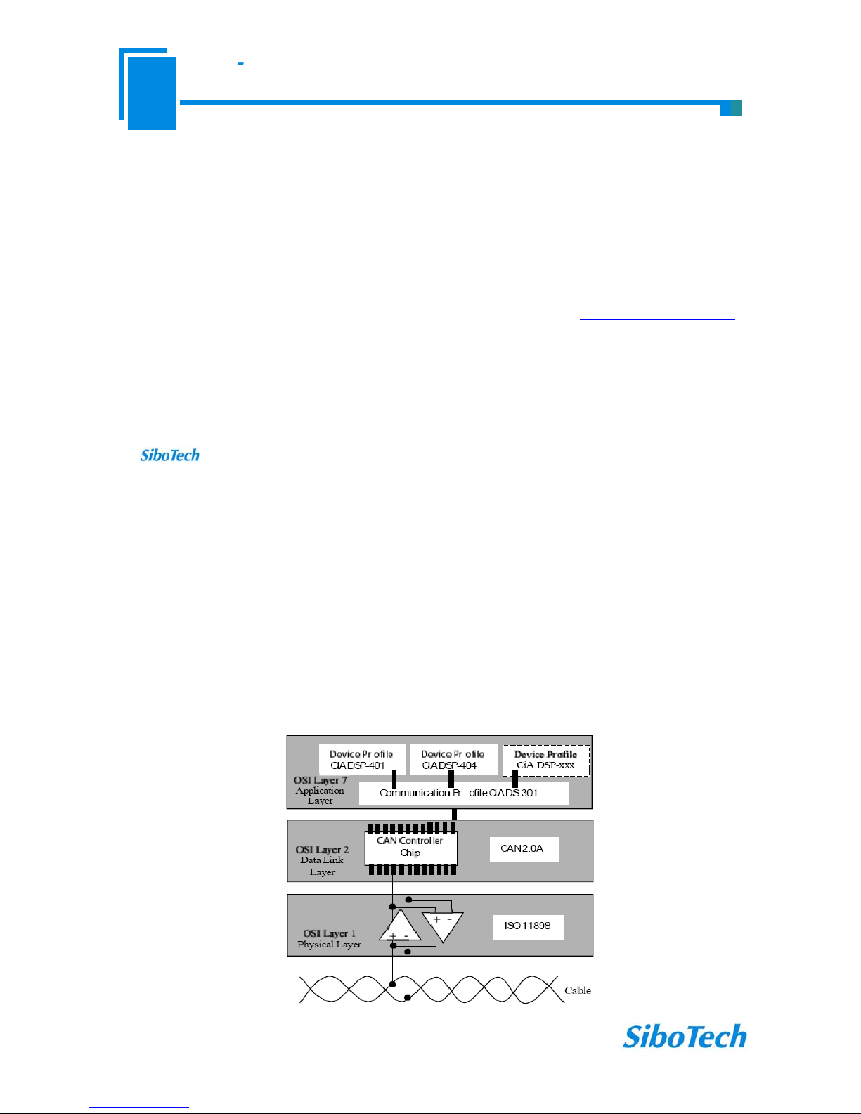
z CANopen: CANopen protocol is one of the standard being defined by CAN-in-Automation (CiA),
CANopen defined application layer (Application layer), communication description (CiA DS-301), device
description (CiA DSP-4XX) , all cable and port (CiA DSP-303) and so on. In OSI model, the relationship
between CAN standard and CANopen protocol is shown as follow:

User Manual
Profibus DP CANopen Gateway-/
PCO 150S
www.sibotech.net
2 About the Gateway
2.1 Product Function
Connects device with CANopen master interface to Profibus-DP network, and establishes communication
between them.
2.2 Feature
¾ Support one CANopen slave interface;
¾ CANopen interface has 1KV photoelectric isolation;
¾ Act as a slave at the side of Profibus-DP network, Profibus baudrate is self-adaptive, and up to 12M;
¾ PROFIBUS input and output bytes can be selected, the maximum number is:
①Max Input Bytes ≤112 Bytes
②Max Output Bytes ≤112 Bytes
2.3 Technical Specification
[1] Communication baudrate:
¾ CANopen baudrate: 50kbit/s,100kbit/s,125kbit/s, 250kbit/s, 500kbit/s, 1Mbps
¾ PROFIBUS-DP baudrate is self-adaptive and can be up to 12M
[2] CAN: ISO 11898-compatible CAN interface is CAN2.0A type with an 11-bit identification
[3] DS-301 V.4.01 and CiA Draft Recommendation 303 compliant
¾ Bytes number of every TPDO and RPDO can not beyond 8
¾ Support expedited Download SDO and expedited Upload SDO
¾ The gateway support up to 42 TPDOs, 42 RPDOs. COB-ID of TPDO and RPDO has default value and
users can user self-defining COB-ID. Default value of Transmit PDO command: 384 + node address
(0x180+node address) or 640 + node address (0x280+node address) or 896 + node address (0x380+node
address) or1152 + node address (0x480+node address); Default value of Receive PDO command: 512 +
node address (0x200+node address) or 768 + node address (0x300+ node address) or 1024 + node address
(0x400+ node address) or 1280 + node address (0x500+node address).
¾ Support up to 42 TPDOs and 42 RPDOs;
¾ Support RPDO time-out reset function and Delay start function;
¾ Support SDO accessing input and output buffer;
¾ Support heartbeat only;

User Manual
Profibus DP CANopen Gateway-/
PCO 150S
www.sibotech.net
[4] Work condition:
¾ Relative Humidity: 5% to 95%(No condensation)
¾ Temperature: -20℃ to 60℃, and the average of 24 hours can not beyond 45℃
¾ Height above sea level can not beyond 2000 meters
¾ Pollution level: 3
[5] EMC testing standard compliant
[6] Power: 24VDC (11V~30V), 90mA (24V)
[7] Mechanical size: 125mm (H)*110mm (W)*40mm (D)
[8] Installation: 35mm rail
2.4 Attention
♦ To prevent stress, prevent module panel damage;
♦ To prevent bump, module may damage internal components;
♦ Power supply voltage control in the prospectus, within the scope of the requirements to burn module;
♦ To prevent water, water module will affect the normal work;
♦ Please check the wiring, before any wrong or short circuit.
2.5 Related products
Related products include:
PCA-100, ENC-310, ENC-311, ENB-302, PCO-150 and so on
More information about these products, please visit:
http://www.sibotech.net/En/, or dial technical support
line: +86-21-5102 8348
User Manual
Profibus DP CANopen Gateway-/
PCO 150S
www.sibotech.net
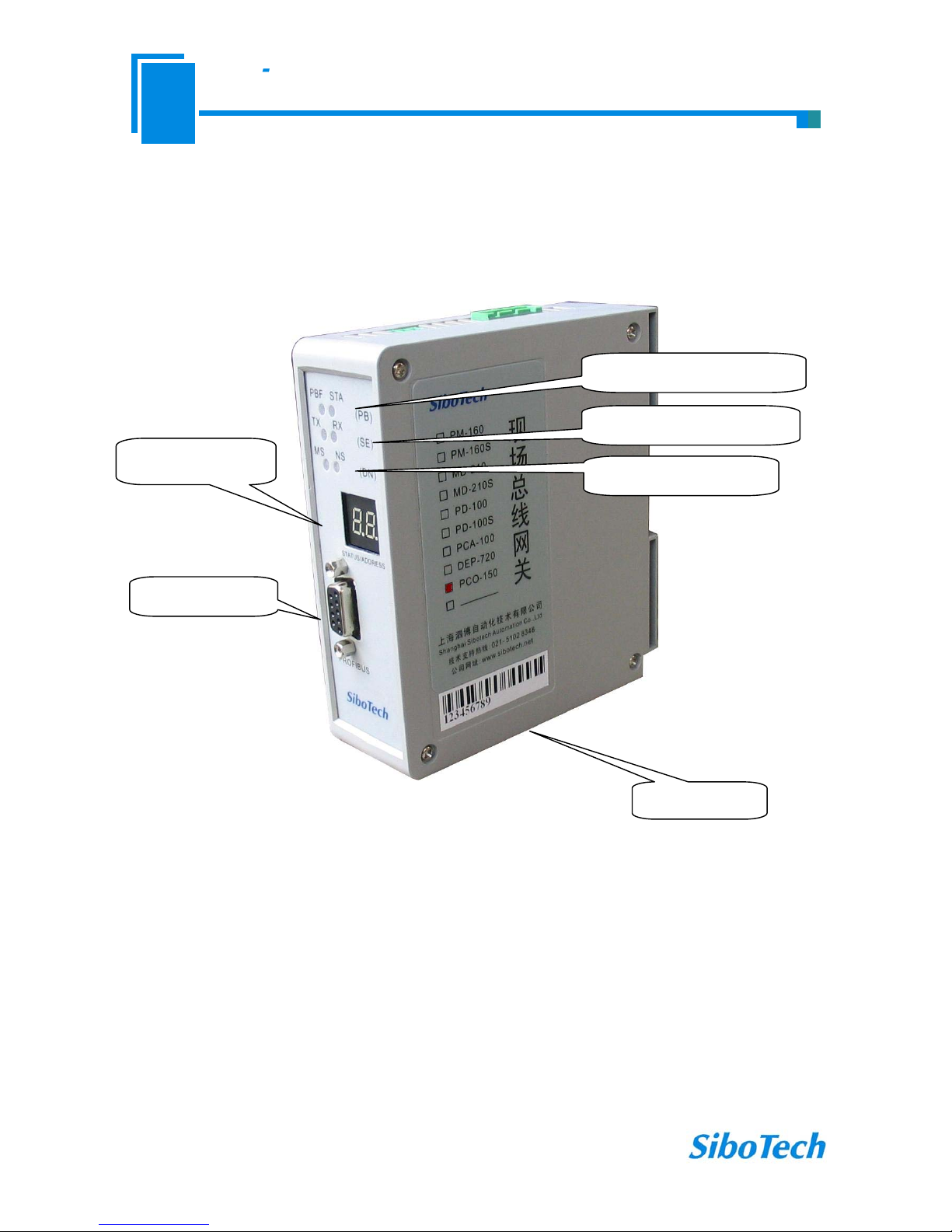
3 External View
Serial port status indicator
Profibus-DP status indicator
Profibus-DP
address/Status
CANopen status indicator
Profibus-DP port
CANopen port

User Manual
Profibus DP CANopen Gateway-/
PCO 150S
www.sibotech.net
3.1Indicators
Indicators Status Description
On Profibus-DP connection has not been established
PBF
(red)
Off Profibus-DP connection has been established
Blinking Exchanging data
Profibus
Status
STA
(green)
Off Profibus-DP status is abnormal
Blinking Serial port is transmitting data
TX
(red)
Off Serial connection fails to establish or error
Blinking Serial port is receiving data
Serial Port
RX
(green)
Off Serial connection fails to establish or error
Red on The CAN controller is bus off
Single flash (red)
At least one of the error counters of the CAN controller has
reached or exceed the warning level (too many error frames)
Orange on The device is in state of configuration
ERR
(bicolor)
Red off No error, the device is in working condition
Green on The device is in state of OPERATIONAL
Single flash (green) The device is in state STOPPED
Blinking (green) The device is in state PRE-OPERATIONAL
CANopen-
STATUS
RUN
(bicolor)
Orange on The device is in state of configuration
User Manual
Profibus DP CANopen Gateway-/
PCO 150S
www.sibotech.net
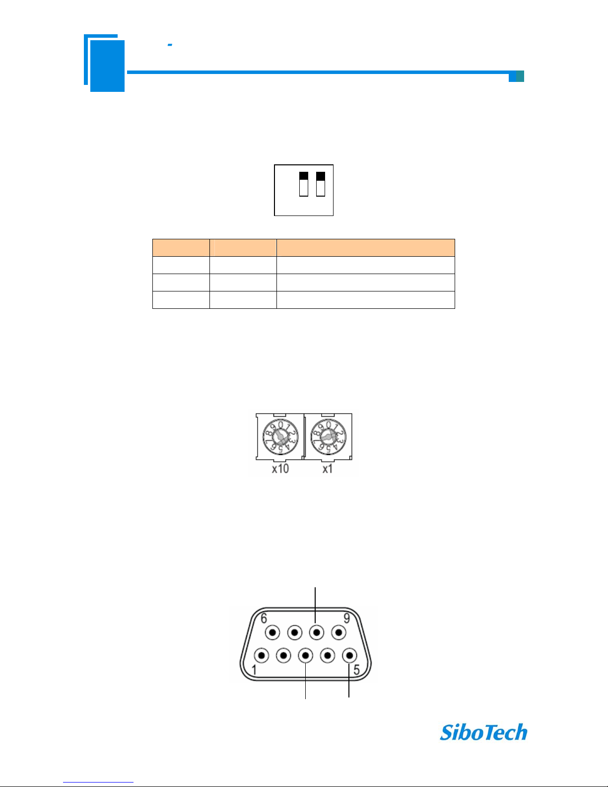
3.2 DIP switches
The 2-switch DIP switch in the bottom is used for setting operating mode of the device.
Off
On
1 2
Status(1) Status(2) Description
X On Configuration mode
On Off Run mode with debug function
Off Off Run mode
Note: “X” is any state.
3.3 Rotary switch
The 2-code rotary switch in the left-side is used for setting the Profibus-DP address of the device.
In this example, the Profibus node address will be 42 (4x10) + (2x1).
3.4 Connectors
3.4.1 PROFIBUS-DP interface
GND
PROFI-B
PROFI-A
 Loading...