

SiboTech HPM-610 User Manual
HART/ PROFIBUS-DP Gateway
HPM-610
User Manual
REV 1.5
SiboTech Automation Co., Ltd.
Technical Support: +86-21-5102 8348
E-mail: gt@sibotech.net

www.sibotech.net
1
Catalog
1 Product Overview...................................................................................................................................................... 3
1.1 Product Summary........................................................................................................................................... 3
1.2 Product Features............................................................................................................................................. 3
1.3 Technical Specifications................................................................................................................................. 3
1.4 Safety and explosion-proof features...............................................................................................................4
1.5 Related Products............................................................................................................................................. 4
2 Quick Start Guide...................................................................................................................................................... 5
2.1 Configuration of Gateway.............................................................................................................................. 5
2.1.1 Pre-configured settings........................................................................................................................ 5
2.1.2 Software configuration........................................................................................................................ 5
3 Hardware Descriptions.............................................................................................................................................. 8
3.1 Product Appearance........................................................................................................................................9
3.2 Indicator LED............................................................................................................................................... 10
3.3 Configuring Switch/button........................................................................................................................... 10
3.3.1 Status setting switch.......................................................................................................................... 10
3.3.2 PROFIBUS-DP/ MODBUS address setting button.......................................................................... 11
3.3.3 Internal / external sampling resistance switch...................................................................................11
3.4 Interface........................................................................................................................................................ 12
3.4.1 Power Interface..................................................................................................................................12
3.4.2 PROFIBUS-DP interface...................................................................................................................12
3.4.3 RS485/RS422 interface..................................................................................................................... 12
3.4.4 RS-232 interface................................................................................................................................14
3.4.5 HART interface..................................................................................................................................14
3.5 Topology of HPM-610 and fieldbus devices................................................................................................15
4 Software Instructions............................................................................................................................................... 17
4.1 Software Interface Description.....................................................................................................................17
4.2 Software Usage.............................................................................................................................................19
4.2.1 Connect to the hardware....................................................................................................................19
4.2.2 Upload the configuration file in the gateway.................................................................................... 19
4.2.3 Configure Fieldbus............................................................................................................................ 20
4.2.4 Configure the HART network........................................................................................................... 22
4.2.5 Conflict detection...............................................................................................................................27
4.2.6 AutoMap............................................................................................................................................ 28
4.2.7 Download configuration file..............................................................................................................28
4.2.8 Memory..............................................................................................................................................29
4.2.9 Diagnose............................................................................................................................................ 30
4.2.10 Serial debug..................................................................................................................................... 33
4.2.11 Switching tools................................................................................................................................ 35
5 Working principle.................................................................................................................................................... 35

www.sibotech.net
2
5.1 Flowchart when performing one HART Command.....................................................................................39
5.2 General Sending and Receiving Data...........................................................................................................39
5.3 Trigger Command.........................................................................................................................................40
5.4 Data Exchange with PROFIBUS-DP........................................................................................................... 41
5.5 Data Exchange with MODBUS....................................................................................................................41
6 In STEP7: Access Data of Gateway and Select Data Module................................................................................ 42
6.1 How STEP7 access data of gateway.....................................................................................................................42
6.2 How STEP7 select data module........................................................................................................................... 43
7 Installation................................................................................................................................................................44
7.1 Machine Dimension......................................................................................................................................44
7.2 Installation Method....................................................................................................................................... 45

www.sibotech.net
3
1 Product Overview
Easy to use: The user simply refers to the product manuals and application examples, configures according to
Powerful function: Supports the interconnection between HART and PROFIBUS-DP/MODBUS, transparent
Abundant debug function: Direct display of data exchange, command diagnosis of HART slave and common
[1] HART can be used as a primary master or the secondary master.
[2] Support only one HART channel; in the multi-point mode, connects 13 devices when using internal register
[3] Supports single-point and multi-points working mode of HART
[4] In single-point mode, supports data burst operation of slave device
[5] Supports all commands of the HART protocol
[6] Each HART command can be configured for change-of-state output, polling output, initialization output or
[7] HART per channel supports up to 128 user commands, HART output data buffer up to 1000 bytes, and the
1.1 Product Summary
HPM-610 is a gateway that can achieve interconnection between HART and PROFIBUS DP and MODBUS.
HART side can be configured as a primary master or the secondary master. PROFIBUS-DP and MODBUS side
can be a slave. The HPM-610’s PROFIBUS DP and MODBUS functionality cannot work simultaneously.
1.2 Product Features
the requirements then it can achieve communication in a short period of time.
transmission between HART and serial (RS232/RS485/RS422).
debugging, these function are very convenient for user's communication test job.
1.3 Technical Specifications
and 15 HART devices when using an external resistor (250Ω).
disable output

www.sibotech.net
4
input data buffer up to 1600 bytes.
[8] Supports internal or external sampling resistor
[9] PROFIBUS side supports DP V0 and slave functionality according to IEC61158
[10] Adaptive baud rate on PROFIBUS-DP(9600 bit/s ~ 12 Mbit/s)
[11] Achieve largest input/output of PROFIBUS protocol: output data bytes
244 bytes, input data
[12] Serial port side can be configured as MODBUS slave, supports function code: 03H, 04H, 06H, 10H.
[13] MODBUS slave supports RTU and ASCII mode
[14] The serial port can be configured as universal mode, and achieve transparent data transmission with HART
[15] Power: 24VDC (9V~30V), 80mA(24VDC);
[16] Operating Temp: -40°F to 158°F (-40 ºC to 70 ºC), Rel. Humidity: 5%-95% ( non-condensing);
[17] External dimension(W*H*D): 40mm* 125mm * 110mm(1.6in*4.9in*4.5in);
[18] Installation: 35mm DIN RAIL;
[19] Protection Level: IP20;
bytes244bytes, the sum of them488bytes
slave devices.
1.4 Safety and explosion-proof features
HPM-610 is NOT the product with the features of safety and explosion-proof, please put it in the control
room when using.
1.5 Related Products
Other related products in SiboTech: HTM-611, HTM-631, HME-615, HME-635, PM-160, EP-321MP and so
on.
If you want to get instruction about these products, please visit SiboTech website:
http://www.sibotech.net/en , or call the technical support phone number: +86-21-5102 8348 ext 8061.

www.sibotech.net
5
2 Quick Start Guide
1. Turn the configuration bit of DIP switch of gateway to “ON”;
2. Connect the RS232 interface of gateway and the serial port of the computer with the serial cable in the
3. Install the configuration software HT-123.
4. Power it on, the digital Led displaying “CF” indicates that the gateway is in the configuring state.
1. Open the HT-123 software installed on your computer.
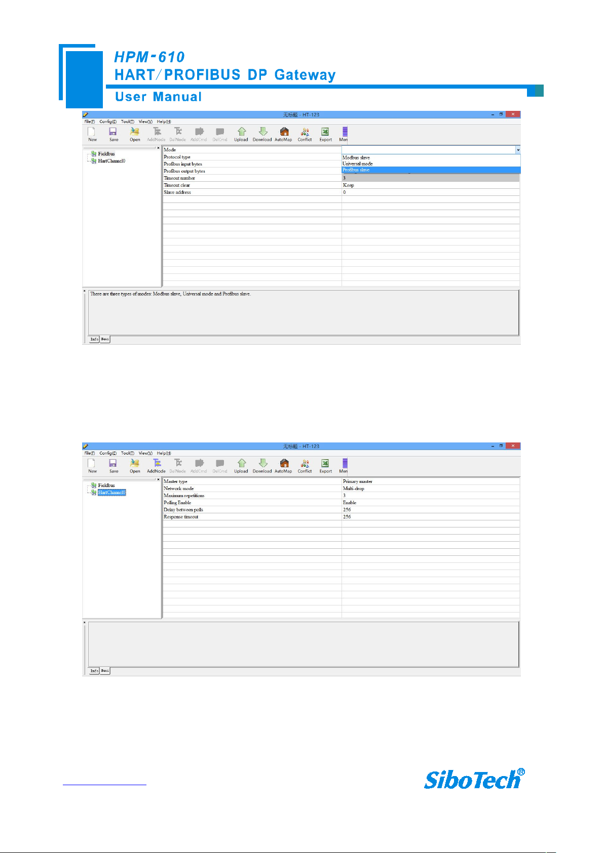
2. Click “Fieldbus” in the tree view on the left, then the configuration table in the figure appears to the right:
The following is an example for using HPM-610. PROFIBUS DP master read the present value of the main
variables (PV) of the HART device which short address is 0.
2.1 Configuration of Gateway
2.1.1 Pre-configured settings
package box. Wiring methods refer to section 3.4.3 of this manual;
Double-click the installed software icon HT-123 to start the gateway configuration.
2.1.2 Software configuration
www.sibotech.net
6
In the first row of the table, Select “PROFIBUS SLAVE”.
3. Click “HartChannel0” in the tree view on the left, with the configuration table in the figure appears to the
When you completed to input the parameter, press “Enter” to confirm.
right:
Then you can completed the configuration of HART network.
Notes: HART protocol specifies that the slave device which address is 0 must work in single-point mode, this
allows digital communication and analog communication to exist at the same time. Slave address 1 to 15 of the
device work in multi-point mode, the analog output of the device is at the minimum value (e.g. 4mA), only allows
www.sibotech.net
7
digital communication. The protocol also specifies that the factory address of HART slave device is 0.
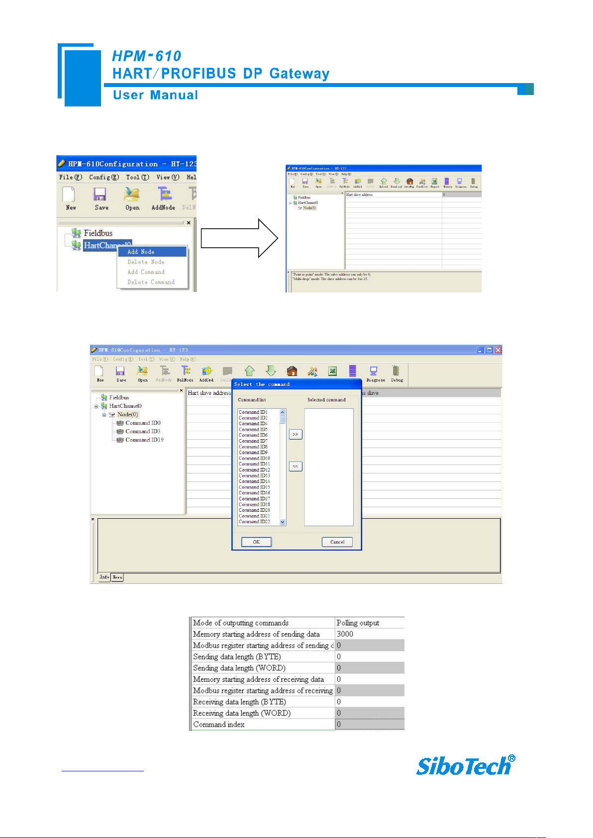
4. Right-click HartChannel0, in the pop-up menu, select “Add Node”, as shown below:
5. Right-click “Node (0)”, in the pop-up menu, select Add command to add a command (command 1), then press
OK to return. The command ID you added will be shown in the left tree.
6. Click the “command ID1”, with the configuration table in the figure appears to the right:
Configure the parameters, then press Enter to confirm.

www.sibotech.net
8
7. Click the icon label, select the serial port with which the gateway is connected to the computer, and
window, you can see the main
variable value of the pressure transmitter:
RS232 Interface
24V
power
supply
Pressure
transmitter
≥250
Ω
HPM-610
Siemens
S7-300
DP port
Computer
STEP 7
RS232 port
PROFIBUS read the
HART data "00, 48, 07,
3A, 3A, BE, C6", the
front two numbers mean
the device state, "07"
indicates that the
pressure unit is bar, "3A,
3A, BE, C6" which
means that the pressure
value, the size is
0.000712376(bar)
+-Loop -
Loop +
then click Download:
2.2 Function Demo
HART interface of the gateway connects with a 2-wire pressure transmitter with slave address 0;
PROFIBUS-DP master uses Siemens S7-300 series PLC, the modeling software uses STEP7. In data exchange
www.sibotech.net
9
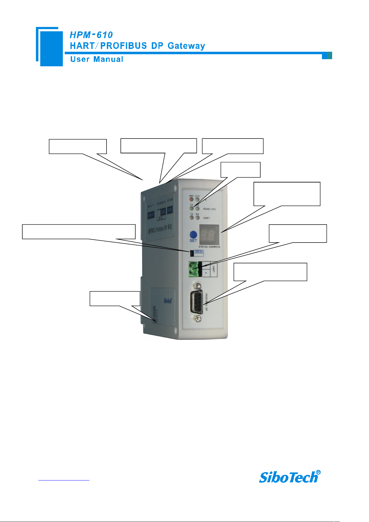
3 Hardware Descriptions
PROFIBUS Interface
HART Interface
24VDC Interface
RS485/RS422 Interface
Indicators
DIP switch
State/address
displaying/setting
RS232 Interface
Selecting switch of sampling resistance
3.1 Product Appearance
Note: This picture is for reference only. Product appearance should accord to the real object.
www.sibotech.net
10
3.2 Indicator LED
Off
On 1 2
Indicator LED State Status Description
PBF
STA
TX
RX
Always Red PROFIBUS DP communication fails
Close Communication is ok.
Green Blinking
Close No data is communicating.
Blinking Bus data is sending
Close No data is sending
Blinking Bus data is receiving
Close No data is receiving
PROFIBUS DP bus data is
communicating
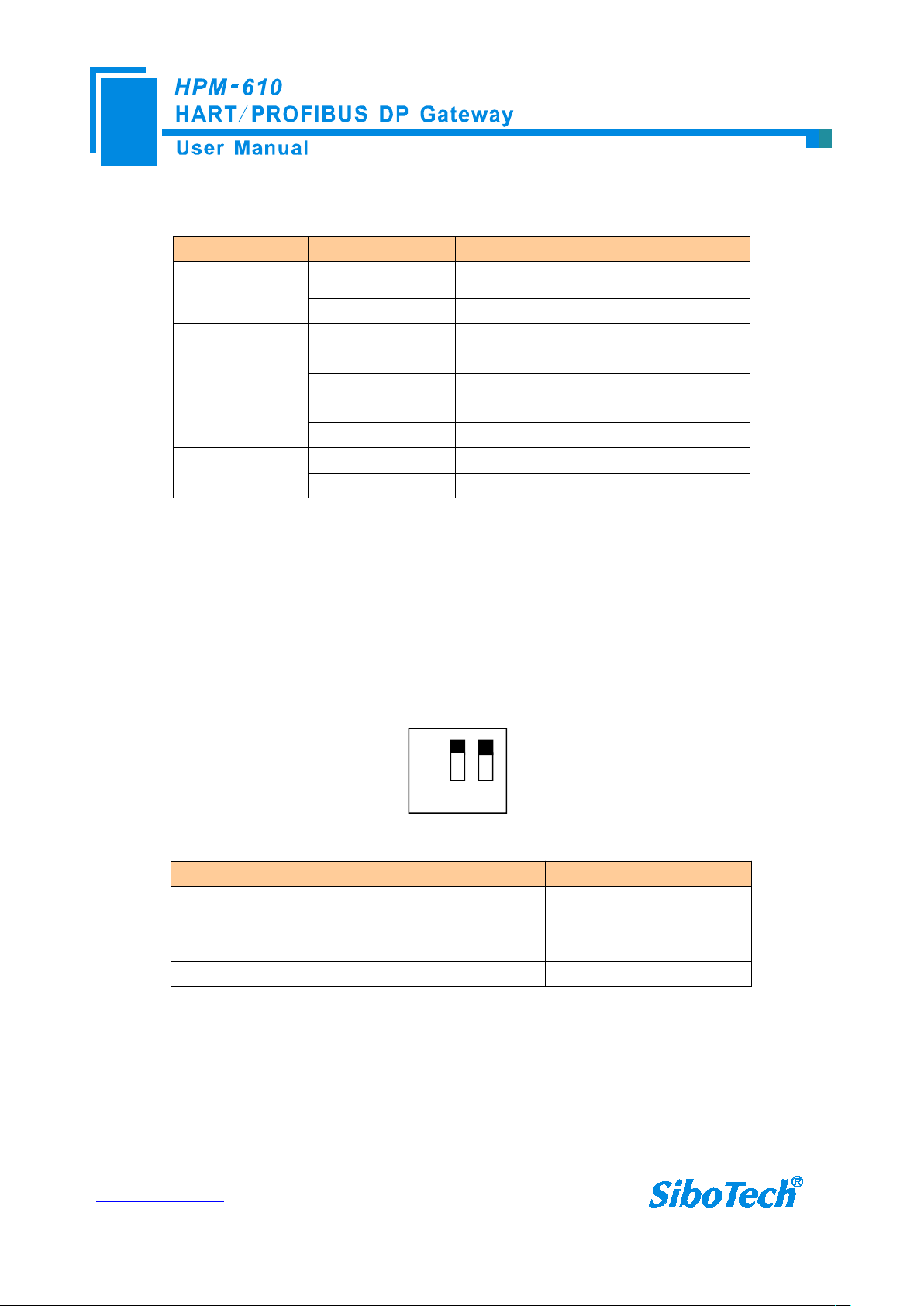
3.3 Configuring Switch/button
3.3.1 Status setting switch
Configuration switch is located at the bottom of product, bit 1 is the debugging bit and bit 2 is the
configuration bit.
The debugging (bit 1) Configuration (bit 2) Description
Off Off Running mode
Off On Configuration Mode
On Off Debugging mode
On On Configuration Mode
Note: ①After configuring the switch, you have to restart the HPM-610 to make the settings take effect!
②Set to debug mode, “MODBUS slave” or “common mode” will be compulsory to appoint RS485
interface acting as the communication port and RS232 interface acting as debugging interface.
③Configuration interface uses the RS232 interface.
www.sibotech.net
11
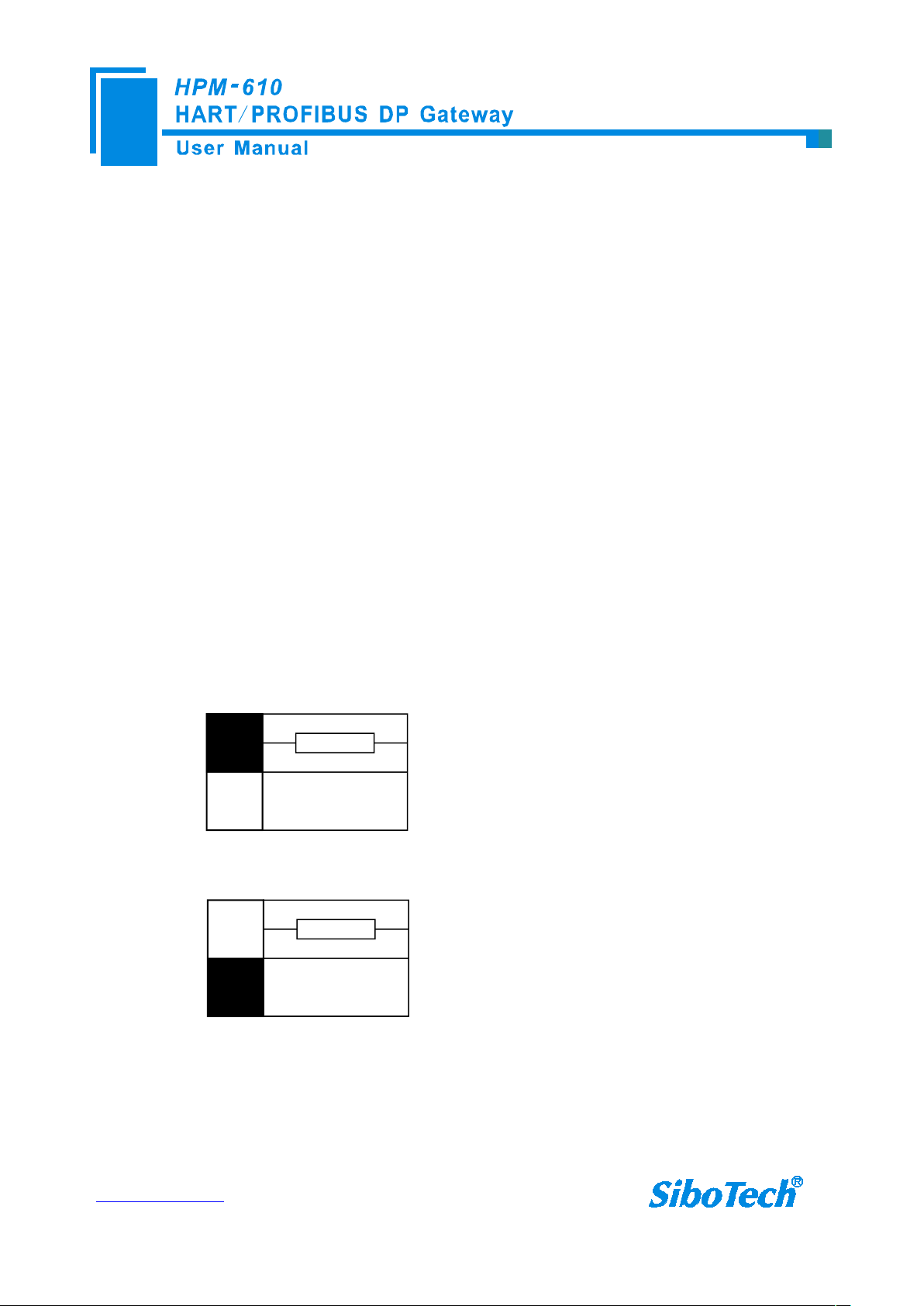
3.3.2 PROFIBUS-DP/ MODBUS address setting button
Switch to the top, using the internal
sampling resistor
270Ω
Switch to the bottom, using an
external sampling resistor
270Ω
Under normal working condition of the HPM-610, press the button twice quickly, then the high bit of digital
LED starts to flash, click the button can set the high bit of PROFIBUS/MODBUS address. Then keep pressing the
button for about 3 seconds, the low bit of digital tube starts to flash, click the button can set the low bit of
PROFIBUS/MODBUS address. Finally, keep pressing the button for about 3 seconds, the address flashing three
times shows that the address was set successfully. After coming in the status of setting PROFIBUS/MODBUS
address, if no button action within ten seconds, HPM-610 exits the status of setting address automatically and
continues to display the original address. The settable range of PROFIBUS/ MODBUS address is 0 to 99
(decimal).
3.3.3 Internal / external sampling resistance switch
Users can choose to use the internal sampling resistor or external sampling resistor to get the HART signal.
The specification of the internal resistor is 270Ω, 2W. When the power of the sampling resistor is more than 2W,
you must choose to use external resistance.
www.sibotech.net
12
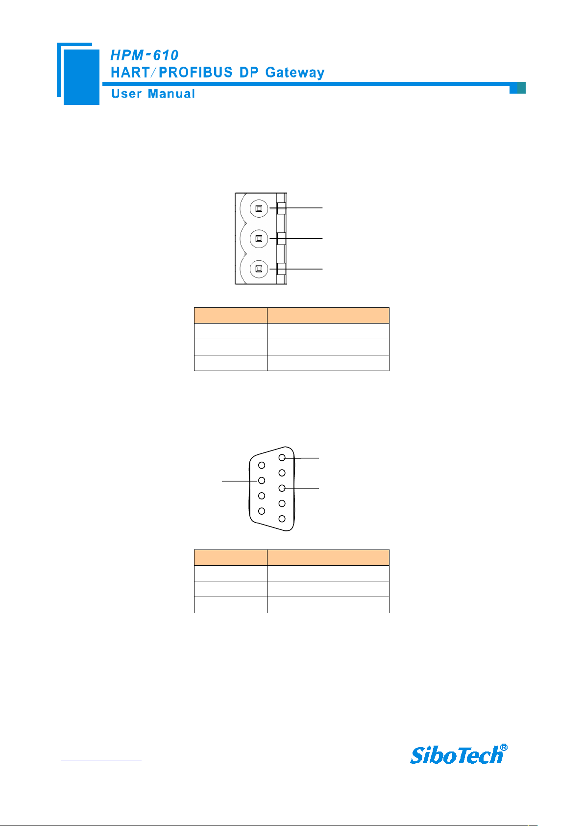
3.4 Interface
GND
NC
24V+
1
2
3
5
1
PROFI_A (Pin 8)
GND (Pin 5)
PROFI_B (Pin 3)
3.4.1 Power Interface
Pin Function
1 GND
2 NC(No Connect)
3 24V+,DC (9-30V)
3.4.2 PROFIBUS-DP interface
PROFIBUS DP interface uses DB9 male-connector, and the pins are defined as follows:
Pin Function
3 PROFI_B, Data positive
5 GND
8 PROFI_A, Data negative
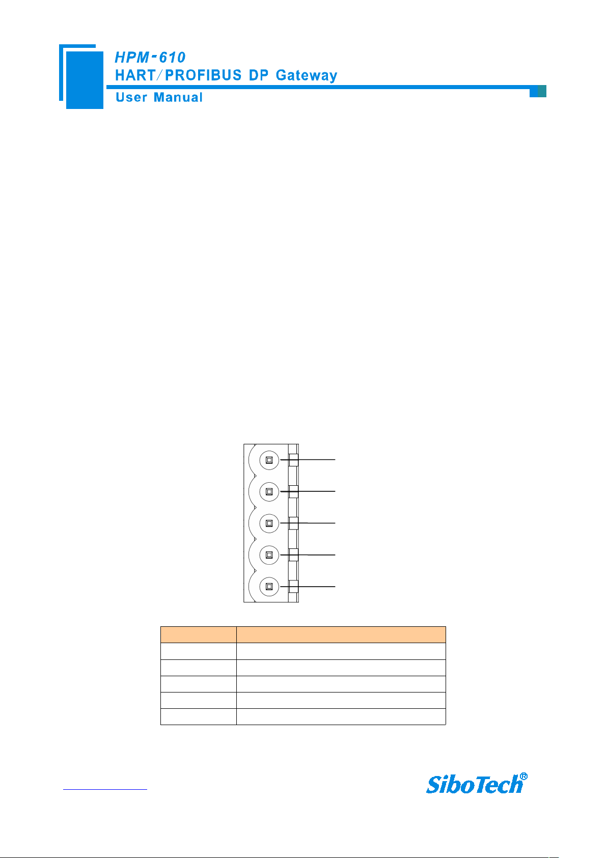
3.4.3 RS485/RS422 interface
The RS-485/422 interface of HPM-610 is a standard RS485/422 compatible port, and this serial port
characteristics of the product will be described as follows:
www.sibotech.net
13
3.4.3.1. The basic characteristics of RS-485 transmission technology
GND
D-
D+
1
2
3
4
5R-R+
① Network topology: Linear bus, there are active bus termination resistors at both sides.
② Transfer rate: 1200 bps~115.2Kbps.
③ Media: Shielded twisted-pair cable and also can cancel the shielding, depending on environmental
conditions (EMC).
④Site number: 32 stations per subsection (without repeater), and can increase to 127 stations (with repeater).
⑤Plug connection: 3-pin pluggable terminal.
3.4.3.2. The main points on RS-485 transmission equipments installation
①All the devices are connected to the RS-485 bus;
②Each subsection can be connected up to 32 sites;
③The two farthest end of each bus provides a termination resistor—120Ω 1/2W to ensure reliable operation
of the network.
Serial interface uses 5-pin pluggable terminal and users can wire it according to the wiring instructions on the
panel.
Pin Function
1 R-, RS-422 Receive Negative
2 R+, RS-422 Receive Positive
3 GND
4 D-, RS-485/RS-422 Transmit Negative
5 D+, RS-485/RS-422Transmit Positive
When you use 2-wire RS485, just connects Pin D+ and D-. If you use 4-wire RS485 or RS422, connects
D+/D- to TX+/TX-.
 Loading...