

SiboTech ENB-302MI User Manual
EtherNet IP / Modbus Gateway
ENB-302MI
User Manual
REV 1.1
Sibotech Automation Co., Ltd
Technical support: +86-021-5102 8348
E-mail: support@sibotech.net

www.sibotech.net
- 2 -
Table of Contents
1 About the Gateway...........................................................................................................................................- 4 -
1.1 Function...................................................................................................................................................- 4 -
1.2 Feature.....................................................................................................................................................- 4 -
1.3 Technical specification........................................................................................................................ - 4 -
2 Rapid Application Guide................................................................................................................................ - 6 -
2.1 Connecting the power.......................................................................................................................... - 6 -
2.2 Connect serial devices......................................................................................................................... - 6 -
2.3 Ethernet connection..............................................................................................................................- 7 -
2.4 Configuration Switch...........................................................................................................................- 8 -
2.5 Installing software................................................................................................................................ - 8 -
3 Hardware Description......................................................................................................................................- 9 -
3.1 Appearance.............................................................................................................................................- 9 -
3.2 Indicators................................................................................................................................................ - 9 -
3.3 Configuration switches......................................................................................................................- 10 -
3.4 Interface.................................................................................................................................................- 10 -
3.4.1 Power interface........................................................................................................................ - 10 -
3.4.2 Ethernet interface.....................................................................................................................- 11 -
3.4.3 RS-485 interface...................................................................................................................... - 11 -
4 Instructions of Configuration Software.....................................................................................................- 13 -
4.1 Notes before configurating............................................................................................................... - 13 -
4.2 User interface.......................................................................................................................................- 14 -
4.3 Operation of equipment view...........................................................................................................- 16 -
4.3.1 Equipment view interface......................................................................................................- 16 -
4.3.2 Operation mode of equipment view....................................................................................- 17 -
4.3.3 Operation types of equipment view.................................................................................... - 17 -
4.4 The operation of configuration view.............................................................................................. - 18 -
4.4.1 Interface of Ethernet configuration view........................................................................... - 18 -
4.4.2 Interface of subnet configuration view...............................................................................- 19 -
4.4.3 Interface of node configuration view..................................................................................- 21 -
4.4.4 Interface of command configuration view........................................................................ - 21 -
4.4.5 Notes View................................................................................................................................- 23 -
4.5 Conflict detect......................................................................................................................................- 23 -
4.5.1 Operation of command list....................................................................................................- 24 -
4.5.2 Operation of memory mapping area................................................................................... - 24 -
4.6 Hardware communication.................................................................................................................- 25 -
4.6.1 Ethernet configuration............................................................................................................- 25 -
4.6.2 Upload configuration..............................................................................................................- 26 -
4.6.3 Download configuration........................................................................................................- 28 -

www.sibotech.net
- 3 -
4.7 Load and save configuration............................................................................................................ - 29 -
4.7.1 Save the configuration project..............................................................................................- 29 -
4.7.2 Load the configuration project.............................................................................................- 29 -
4.8 Output excel document......................................................................................................................- 29 -
4.9 Debug.....................................................................................................................................................- 30 -
5 EtherNet/IP Connection Parameters...........................................................................................................- 33 -
6 Typical Application........................................................................................................................................- 34 -
7 Installation........................................................................................................................................................- 35 -
7.1 Mechanical Dimensions.................................................................................................................... - 35 -
7.2 Installation............................................................................................................................................- 35 -
8 Attention........................................................................................................................................................... - 37 -
9 Copyright Information...................................................................................................................................- 38 -
10 Related Products...........................................................................................................................................- 39 -

www.sibotech.net
- 4 -
1 About the Gateway
Redundant Power Supply
Two independent RS485 interfaces 1KV optical isolation
Ethernet 10/100M adaptive
IP address conflict detection
Modbus network debugging
Easy to use configuration software GT-123
1.1 Function
Through the conversion between EtherNet IP protocol and Modbus protocol of ENB-302MI, Modbus serial
devices can access EtherNet IP network, bi-directional and easily exchange data.
1.2 Feature
1.3 Technical specification
[1] EtherNet / IP network is independent with two Modbus networks;
[2] Ethernet 10/100M adaptive;
[3] Support IP addresses conflict detection function;
[4] Support the ODVA Standard EtherNet / IP communication protocol;
[5] Two serial RS485 interfaces, half-duplex, and baud rate support: 1200, 2400, 4800, 9600, 19200, 38400,
57600, 115200; parity mode support: none, odd, even, mark, space; 1 or 2 stop bits;
[6] ENB-302MI act as master at the side of Modbus network and support 01H, 02H, 03H, 04H, 05H, 06H, 0FH,
10H function codes, can be configured up to 48 Modbus commands for each RS485 interface; Modbus function

www.sibotech.net
- 5 -
codes 03H, 04H, 06H and 10H support "Byte swap" function, and it can help users solve the problem of data
format between two different networks;
[7] Two independent RS485 interfaces 1KV optical isolation;
[8] The maximum number of input and output bytes of EtherNet / IP:
Maximum number of input bytes: 512Bytes
Maximum number of output bytes: 512Bytes
[9] Power supply: 24VDC (11V ~ 30V), 90mA (24VDC);
[10] Working temperature: -20 ℃ ~ 60 ℃, relative humidity: 5% ~ 95% (no condensation);
[11] Dimensions: 40mm (width) × 125mm (height) × 110mm (depth);
[12] Installation: 35mm rail;
[13] Protection class: IP20;
[14] Test standard: EMC test standards
www.sibotech.net
- 6 -
2 Rapid Application Guide
GND
NC
24V+
1
2
3
GND
24V+
DC power: +24V Ⅰ
Power interface of ENB-302MI
GND
NC
24V+
1
2
3
GND
24V+
Optionally be connected
Must be connected
Power interface of ENB-302MI
(the other)
DC power: +24V Ⅱ
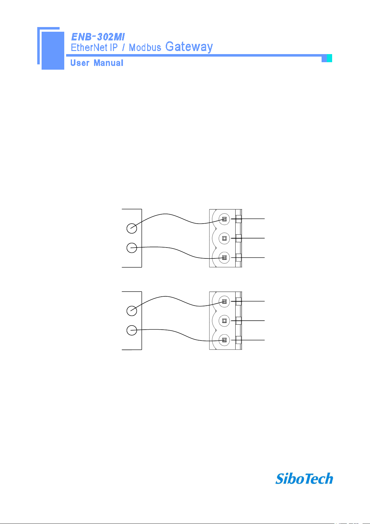
2.1 Connecting the power
DC 24V power supply, dual power supply interface, a redundant function, users can use one or two power supply.
If you are using two power supply, when the way in which the power fails, the other way you can continue to
supply power to ensure normal operation.
Power supply wiring as shown below:
2.2 Connect serial devices
RS485 connection as shown below:

www.sibotech.net
- 7 -
B+A-GND
1
2
3
485+
485-
RS485 device 1
RS485 interface
RS485 device 2
RS485 device 3
485+
485-
485+
485-
…
In order to prevent signal reflection and interference in RS485 multipoint communication, adding one
terminal resistor at the both farthest ends of the line is necessary, and the argument is 120Ω 1/2W.
Note: There is no internal termination resistor in the RS485 interface of ENB-302MI.
2.3 Ethernet connection
Ethernet interface apply RJ-45 connector, 10/100M adaptive.
www.sibotech.net
- 8 -
Pin
Signal Description
S1
TXD+,Tranceive Data+, Output
S2
TXD-,Tranceive Data-, Output
S3
RXD+,Receive Data+, Input
S4
Bi-directional Data+
S5
Bi-directional Data-
S6
RXD-,Receive Data-, Input
S7
Bi-directional Data+
S8
Bi-directional Data-
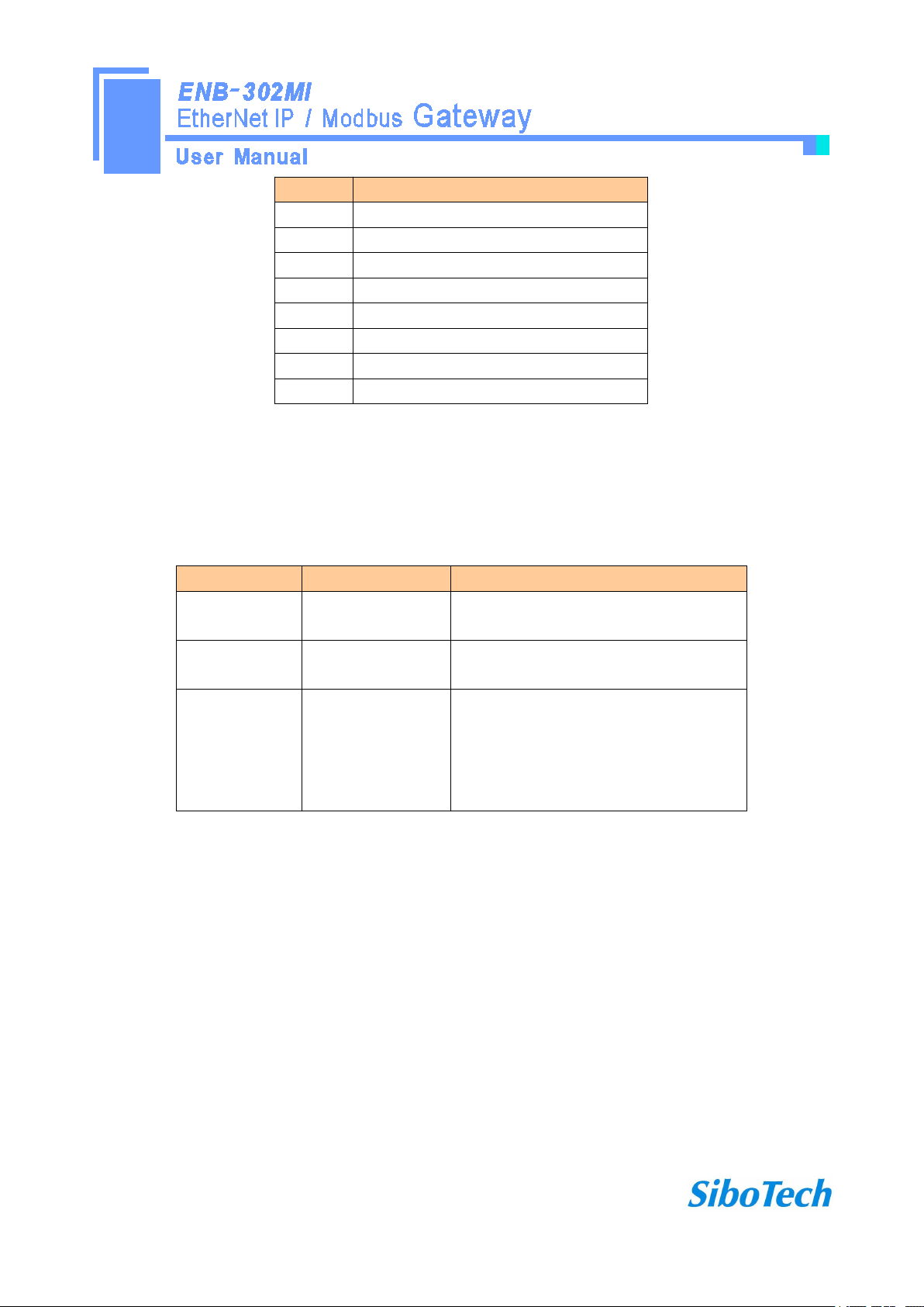
2.4 Configuration Switch
Mode bit (bit 1)
Function bit (bit 2)
Description
Off
Off
Operation mode, allowing read and write
configuration data
Off
On
Operation mode, read and write
configuration data against
On
Off or On
Configuration mode, IP address is fixed at
192.168.0.10, this mode can only read and
write configuration data, can not
communication between EtherNet / IP and
Modbus network
Configuration switches located on the bottom of the gateway, set the mode bit (bit 1) to 0 (Off), and set
function bit (bit 2) to 0 (Off), power (or restart) the device to work.
2.5 Installing software
Take the product CD into the computer CD drive, open the CD, install the configuration software GT-123.
You can easily follow the prompts to complete the installation. Then open the configuration software and finish
the configuration of ENB-302MI!
Note: The factory set of ENB-302MI is DHCP, if the network is no DHCP Server, you can set mode bit (bit
1)to 1(On), and restart ENB-302MI, then the fixed IP address of ENB-302MI is 192.168.0.10, mask is
255.255.255.0, gateway address is 192.168.0.1.
www.sibotech.net
- 9 -
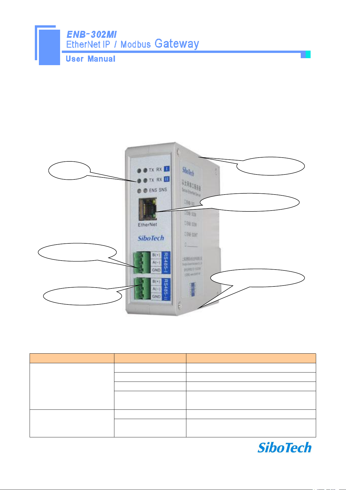
3 Hardware Description
Indicator
Status
Description
ENS
Always green
EtherNet / IP connection is established
Green flashing
EtherNet / IP connection is not established
Always red
IP address indicates a conflict
Red flashing
EtherNet / IP connection timed out; DHCP, BOOTP ,
IP address conflict detection
SNS
Always green
Modbus Communication normal
Always red
At least one Modbus network response timeout,
exception or error
Ethernet RJ-45 interface
RS-485interfaceⅠ
RS-485interfaceⅡ
Configuration switches
Power interface
Indicator
3.1 Appearance
3.2 Indicators
www.sibotech.net
- 10 -
Alternately flashing red
and green light
At least part of one Modbus network timeout, an
exception or error
ENS orange light and SNS
orange light
(orange light: Red and green
light at one time)
Light at one time
Start status
Flash alternately
Configuration mode
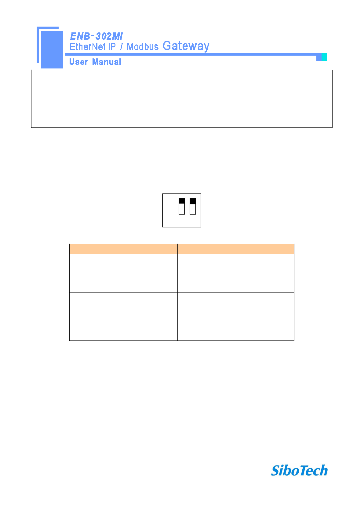
3.3 Configuration switches
Off
On 1 2
Mode bit (bit 1)
Function bit (bit 2)
Description
Off
Off
Operation mode, allowing read and write
configuration data
Off
On
Operation mode, read and write
configuration data against
On
Off or On
Configuration mode, IP address is fixed at
192.168.0.10, this mode can only read and
write configuration data, can not
communication between EtherNet / IP and
Modbus network
Configuration switch locate on the bottom, bit 1 is mode select bit, bit 2 is function set bit.
Note: Restart ENB-302MI after resetting the configuration and the configuration can take effect!
3.4 Interface
3.4.1 Power interface
ENB-302MI has two power interfaces, with power redundancy function, when one the way to power failure,
power can continue to supply the other way.

www.sibotech.net
- 11 -
GND
NC
24V+
1
2
3
引脚
功能
1
GND,
2
NC, no connection
3
24V+ , DC
3.4.2 Ethernet interface
Pin
Signal Description
S1
TXD+,Tranceive Data+, Output
S2
TXD-,Tranceive Data-, Output
S3
RXD+,Receive Data+, Input
S4
Bi-directional Data+
S5
Bi-directional Data-
S6
RXD-,Receive Data-, Input
S7
Bi-directional Data+
S8
Bi-directional Data-
Ethernet interface apply RJ-45 connector, 10/100M adaptive.
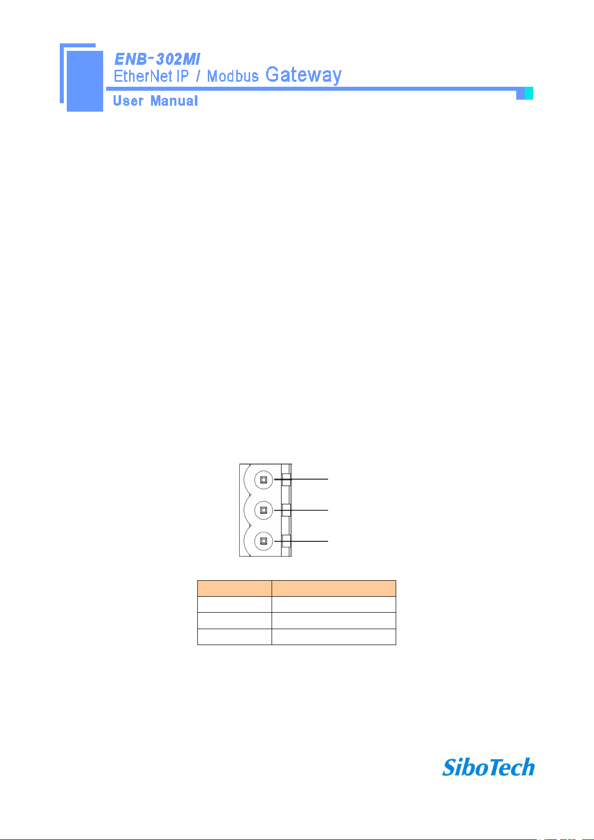
3.4.3 RS-485 interface
The RS-485 interface of ENB-302MI is standard, and the RS-485 characteristics of the product are shown
as follows:
www.sibotech.net
- 12 -
1. The basic characteristics of RS-485 transmission technology
B+A-GND
1
2
3
Pin
Function
1
B+,RS485
2
A-,RS485
3
GND
① Network topology: Linear bus, there are active bus termination resistors at both sides.
② Transfer rate: 300 bps~115.2Kbps.
③ Media: Shielded twisted-pair cable and also can cancel the shielding, depending on environmental
conditions (EMC).
④Site number: 32 stations per subsection (without repeater), and can up to 127 stations (with RS485
repeater).
⑤Plug connection: 3-pin pluggable terminal.
2. The main points on RS-485 transmission equipments installation
①All the equipments be connected with RS-485 bus;
②Subsection can be connected up to 32 sites;
③The farthest end of each bus has a termination resistor—120Ω 1/2W to ensure reliable operation of the
network.
Serial interface uses 3-pin pluggable terminal and users can wire it according to the wiring instructions on the
panel.
 Loading...