

Sib Geofiz Pribor SGD-TG Operation Manual

Sib Geofiz Pribor Ltd, Research-and-Manufacturing company
Geophone Tester SGD-TG
Operations Manual
October 2011

Sib Geofiz Pribor Ltd
CONTENTS
1. Introduction .................................................................................................................................. 4
1.1. Purpose .................................................................................................................................. 4
1.2. Technical support .................................................................................................................. 4
2. Performance specifications .......................................................................................................... 5
2.1. Geophone natural frequency ................................................................................................. 5
2.2. Geophone damping ............................................................................................................... 5
2.3. Geophone sensitivity ............................................................................................................. 5
2.4. Geophone coil electrical resistance ....................................................................................... 5
2.5. Geophone total harmonic distortion ..................................................................................... 5
2.6. Geophone electrical impedance ............................................................................................ 5
2.7. Geophone leakage resistance ................................................................................................ 5
2.8. External temperature sensor .................................................................................................. 6
2.9. Geophone testing procedure duration ................................................................................... 6
2.10. Built-in flash memory capacity ........................................................................................... 6
2.11. Computer connection .......................................................................................................... 6
2.12. Power supply ....................................................................................................................... 6
2.13. Operation conditions ........................................................................................................... 6
2.14. Transportation and storage conditions ................................................................................ 6
2.15. Overall dimensions ............................................................................................................. 7
2.16. Mass ................................................................................................................................... 7
2.17. Completeness ..................................................................................................................... 7
3. Built-in battery ............................................................................................................................. 7
3.1. Maintenance and care .......................................................................................................... 7
3.2. Charging ............................................................................................................................... 8
4. Working with the Tester .............................................................................................................. 9
4.1. Design ................................................................................................................................... 9
4.2. Switching On and Off ......................................................................................................... 10
4.3. Tester Menu Navigation ..................................................................................................... 11
4.4. Menu Structure ................................................................................................................... 13
4.4.1. Setup menu… - Geophone menu ................................................................................. 14
4.4.2. Setup menu… - String menu… ................................................................................... 17
4.4.3. Setup menu… - Sequence of tests… ........................................................................... 18
4.4.4. Setup menu… - Operation conditions ......................................................................... 23
4.4.5. Setup menu… - Date & Time ...................................................................................... 24
4.4.6. Setup menu… - Default settings .................................................................................. 25
4.4.7. Setup menu… - Read settings ...................................................................................... 26
4.4.8. Setup menu… - Save settings ...................................................................................... 26
4.4.9. Memory menu… ......................................................................................................... 26
4.4.10. Display settings… ...................................................................................................... 28
4.4.11. HW diagnostics… - Display ...................................................................................... 29
4.4.12. HW diagnostics… - Sine wave generator .................................................................. 30
4.4.13. HW diagnostics… - Self-test ..................................................................................... 30
4.4.14. HW diagnostics... - Power ......................................................................................... 31
4.5. Testing a Geophone string .................................................................................................. 31
5. Interaction of the Tester with PC ............................................................................................... 33
5.1. USB Driver Installation ...................................................................................................... 34
5.2. Uploading Test Results to the PC ....................................................................................... 37
5.3. Updating the Tester firmware ............................................................................................. 43
2

Sib Geofiz Pribor Ltd
6. Connection Diagrams ................................................................................................................ 45
3

Sib Geofiz Pribor Ltd
1. Introduction
This Operations Manual is intended to study the design, purpose and operating principle
and to obtain the information required for proper operation and full use of technical
capabilities of the Geophone Tester SGD-TG SGFP.070.00.00 (hereinafter—the
Tester).
The information presented in this Manual refers to the Tester firmware Version 2.1
(October, 2011).
1.1. Purpose
The SGD-TG Tester is designed to measure parameters both of individual geophones
and of geophone strings having various configurations.
The Tester operation does not require connection to a computer or to an external power
supply. The Tester has a built-in rechargeable battery with the 6V voltage and 3.3AH
rated capacity. The Tester with a fully charged battery can provide continuous service
during at least 8 hours. The Tester is furnished with a built-in charger. Charging the
built-in battery requires an external power supply or a 12 Volt battery. The Tester
operation can remain uninterrupted in the course of charging.
The Tester has a built-in non-volatile (flash) memory to store geophone testing and selftesting results. The built-in memory capacity is sufficient to store 32,756 entries. An
external computer connected via USB interface is used to upload accumulated data.
The data is rewritten to the computer in the form of two files, the first of which contains
the geophone (geophone string) testing data, and the second one—self-testing data.
The files are created in text format suitable for import into spreadsheet programs (such
as MS Office Exсel).
The Tester contains a geophone reference data library divided in two parts: read-only
and user-defined libraries. The read-only library cannot be edited or deleted. The userdefined library shall be created by the User through copying entries from the read-only
library with subsequent editing. Data can be freely removed from the user-defined
library.
The Tester is equipped with a remote temperature sensor designed for correction of the
geophone test results.
The Tester firmware can be upgraded via USB interface without opening the Tester
housing. The User can receive a new firmware-containing file via e-mail.
1.2. Technical support
Information on the available firmware updates and other technical issues can be
obtained via e-mail sgd@sibgeodevice.ru.
4

Sib Geofiz Pribor Ltd
2. Performance specifications
When measuring geophone (geophone string) specifications, the Tester pre-calculates
the rated value of any parameter to be measured and, based on this value, chooses the
test signal amplitude and the measuring channel parameters and, consequently, the
range of measurements. Therefore, the Tester performance specifications presented in
2.1 – 2.5 are valid provided the deviation of the measured quantity from its rated value
is no more than ±50%.
All performance specifications of the Tester are given for normal environmental
conditions.
2.1. Geophone natural frequency
Measurement range: 1.5 Hz to 100 Hz;
Relative measurement error: no more than ±1%;
Resolution: 0.01 Hz.
2.2. Geophone damping
Measurement range: 0.1 to 0.85;
Relative measurement error: no more than ±1.5%;
Resolution: 0.001
2.3. Geophone sensitivity
Measurement range: 0 to 6553.5 V/(m/s)*;
Relative measurement error: no more than ±2%;
Resolution: 0.1 V/(m/s).
*The sensitivity is calculated based on the results of measuring other geophone
parameters using the reference value of the geophone moving mass provided by the
geophone manufacturer.
2.4. Geophone coil electrical resistance
Measurement range: 0 to 65,535 Ohm;
Relative measurement error: no more than ±1%;
Resolution: 1 Ohm.
The electric resistance is determined by direct current measurement.
2.5. Geophone total harmonic distortion
Measurement range: 0 to 30%;
Absolute measurement error: no more than ±0.01%;
Resolution: 0.01%.
2.6. Geophone electrical impedance
Measurement range: 0 to 65,535 Ohm;
Resolution: 1 Ohm.
2.7. Geophone leakage resistance
Measurement range: 1 MΩ to 100 MΩ;
Relative measurement error: no more than ±5%;
5

Sib Geofiz Pribor Ltd
Resolution: 0.1 MΩ.
The leakage resistance is measured under constant voltage no more than 3.0V.
2.8. External temperature sensor
Measurement range: -40ºС to +70ºС;
Absolute measurement error: no more than ±1.5ºС;
Resolution: 1ºС.
2.9. Geophone testing procedure duration
The geophone (geophone string) testing procedure duration with the polarity test
disabled is no more than 15 s.
2.10. Built-in flash memory capacity
The Tester uses 8 MB built-in flash memory which allows storing up to 32,756 entries.
2.11. Computer connection
The Tester can be connected to a PC via USB interface compatible with USB 2.0 full
speed (12Mbit/s) self-powered.
2.12. Power supply
Built-in battery capacity: 3.2 AH;
Built-in battery rated voltage: 6 V;
Battery type: maintenance-free lead-acid battery;
Permissible temperature range of the battery: -20ºС to +60ºС;
Continuous running time with a fully charged built-in battery: at least 8 hours;
Built-in battery charging duration: no more than 10 hours;
Voltage range of an external DC power supply: 10.5 V to 16 V;
Maximum current consumed from an external power supply during charging with the
Tester switched on: 0.5 A under 12 V voltage;
Maximum current consumed from an external power supply during charging with the
Tester switched off: 0.3 A under 12 V voltage;
Built-in real time clock is supplied from the CR2032 lithium battery with the service
life no less than 3 years.
2.13. Operation conditions
The Tester is designed for operation under conditions preventing direct action of
atmospheric precipitation (rain, snow, etc.) at relative humidity from 5 to 95%;
Operating temperature range: - 20ºС to +60ºС.
2.14. Transportation and storage conditions
The Tester can be transported by any mode of transport at ambient temperature
from - 30ºС to +60ºС and relative humidity from 5 to 95 %;
The tester is to be stored in warehouse premises preventing direct action of
atmospheric precipitation (rain, snow, for, etc.) at ambient temperature from - 30ºС
to +60ºС and relative humidity from 5 to 95 %;
Storage of the Tester along with evaporating liquids, acids and other substances,
which can cause metal corrosion and insulation failure, is prohibited.
6

Sib Geofiz Pribor Ltd
2.15. Overall dimensions
The Tester dimensions are no more than 240х155х65 mm (LxWxH).
2.16. Mass
The Tester mass without accessories is no more than 2.5 kg.
2.17. Completeness
Tester with 6 V, 3.2Ah battery;
AC/DC 12 V, 1 A mains adapter;
Geophone and Remote temperature sensor connection cable;
Compact disk containing documentation and software;
Packing bag for storage and carriage of the Tester and additional accessories.
3. Built-in battery
3.1. Maintenance and care
The built-in battery (hereinafter—the battery) requires careful handling. Observe the
main rules to extend the battery service life.
Do not allow deep discharge of the battery.
Even with the Tester switched off, the battery continues discharging owing to selfdischarge process and to the current consumed by the switching on / off circuit
(approximately 10 μA). At high temperatures, the self-discharge process accelerates. If
the battery voltage drops down to 4.5 volts and below, the battery capacity irreversibly
decreases, after which the battery cannot be fully charged.
Before long-term storage of the Tester (more than 1 month), the battery
should be fully charged and then disconnected.
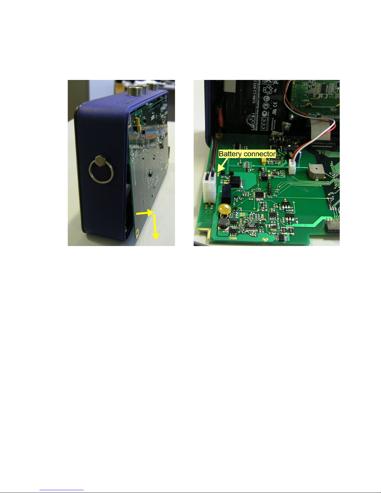
To disconnect the battery, remove the Tester rear cover by unscrewing 4 fixing screws,
lift the lower unsecured edge of the main printed-circuit board (PCB) (Fig. 1) and shift it
so that the PCB connectors disconnect from the counterparts on the filter board. Throw
the main PCB sideward and disconnect the power wires from the PCB connector
(Fig.2). Replace the PCB and close the Tester rear cover. Upon completion of storage
and prior to using the Tester, re-connect the battery and recharge it.
Do not allow storage of the Tester with a discharged battery at low negative
temperatures.
As the battery discharges, the electrolyte concentration decreases, owing to which
electrolyte may freeze. Electrolyte freezing may cause irreversible mechanical damages
of the battery elements. Besides, at low temperatures, the battery capacity drops down.
Thus, at a temperature of -20°С, the battery capacity is 40% of the rated value.
Charge the battery on a regular basis.
The Tester starts giving audible signals every 10 seconds, if the battery voltage drops
down to 5.4 V during operation. These signals mean that the battery requires charging.
7
Sib Geofiz Pribor Ltd
If during operation the battery voltage drops down to 5.3 V, the Tester will be
automatically switched off after giving three audible signals in succession. In attempting
to switch on power supply of the Tester, the battery of which is discharged to 5.3 V and
below, the Tester is switched on, gives a triple audible signal and is switched off right
away.
Figure 1 Figure 2
3.2. Charging
The battery can be charged using the mains adapter included in delivery, an external
storage battery with the 12 V rated voltage or any other external power supply with a
voltage from 10.5 to 16 volts and permissible load current no less than 0.5A. The
Tester is furnished with built-in circuits to ensure protection against backward voltage,
over-voltage and current overload upon connection of an external power supply.
ATTENTION! When using an external power supply operating from 220AC
mains, it is necessary to make sure first that it functions properly. The DC
output circuit should be galvanically isolated from the AC input circuit!
Connect an external power supply to the “+12V” socket of the Tester. If the external
power supply voltage is within the permissible limits, the battery starts charging as
demonstrated by flashing green light of the LED indicator. Steady red light shows that
the external power supply voltage is beyond the permissible limits or current consumed
from the external power supply has exceeded 1A.
During charging it is permissible to switch on the Tester and use it for the purpose
intended. The Tester consumes no power from the built-in battery either during charging
or upon its completion, being powered by the external supply as long as it is connected.
After disconnection of the external power supply, the Tester will automatically switch to
8
Sib Geofiz Pribor Ltd
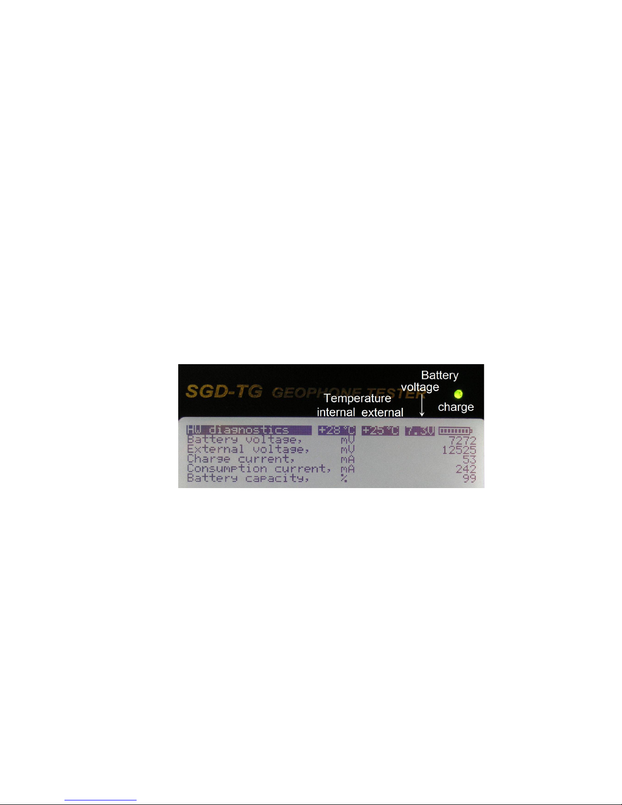
operation from its battery. When the Tester is in the switched on state in the course of
charging, the top line of its display shows voltage (in volts) at the battery terminals and
the state of its charge in the form of AA battery symbolic representation. You can
monitor a status of the battery on the screen by entering the menu “Main menu” -> "5
Hardware diagnostics" -> "4 Power" (Fig. 3).
Nominal charging current is 380mA. When the battery voltage reaches 7.2...7.3V, the
charging current begins to decrease gradually. The charging current decreases up to
20% from nominal at achievement of capacity of the battery about 90%. From this point
the green LED lights on and off alternately. If necessary, at this point you can stop
charging. However, when possible, you should continue to charge. The battery is fully
charged when the charging current drops below 10% of nominal. Since then, the charge
is terminated, and the green LED is permanently lit.
It is recommended to charge the battery at a temperature from +10 to +40°С.
Charging time of a discharged battery at room temperature is approximately 10 hours.
Completion of charging is evidenced by steady green light of the LED indicator.
Charging at low temperatures does not enable the battery to reach full capacity. Monitor
the temperature inside the tester housing by readings of the built-in temperature sensor
shown on centre in the display top line. Readings of the remote temperature sensor are
indicated rightwards.
Figure 3
4. Working with the Tester
4.1. Design
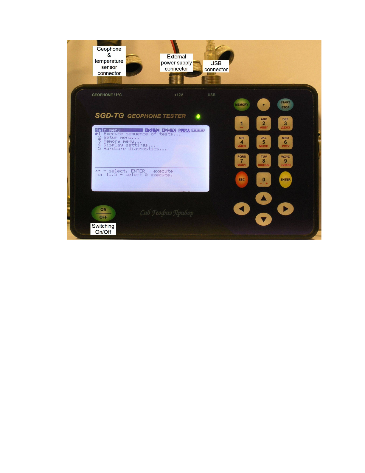
The Tester front panel accommodates a graphic display with 240 х 128 point resolution,
a bi-colour LED indicator and a keyboard (Fig. 4). The ON/OFF button intended to
switch on and off the Tester is located in the lower left corner of the front panel.
Three connectors are provided on the housing frame:
“GEOPHONE/t°C” for connection of geophones and the remote temperature sensor;
“+12 V” for connection of the external power supply;
“USB” for PC connection.
The tester housing has a detachable rear cover. The cover is secured by four screws.
9
Sib Geofiz Pribor Ltd
Figure 4
4.2. Switching On and Off
To switch on the Tester, press the ON/OFF button once. At the instant of switching on,
the Tester checks voltage across the battery terminals. If the battery voltage is lower
than or equal to 5.3V, the Tester will give a triple audible signal and turn off
automatically. When the battery voltage drops down to 5.4V in the course of operation,
the Tester will give audible signals every 10 seconds to signalize the necessity of
battery charging.
The battery is charged with a connected external power supply, irrespective of whether
the Tester is switched on or off. After switching on, the Tester is operated from the
external power supply (if it is connected) or from the built-in battery (if the external
power supply is not connected).
Once the Tester is switched on, the program is loaded and all units are initialized. As
this takes place, a splash screen specifying the version number and firmware release
date is displayed. Upon completion of loading, the main menu is displayed, following
which the Tester is ready for operation.
10
Sib Geofiz Pribor Ltd
The tester is switched off by one-off pressing the ON/OFF button.
4.3. Tester Menu Navigation
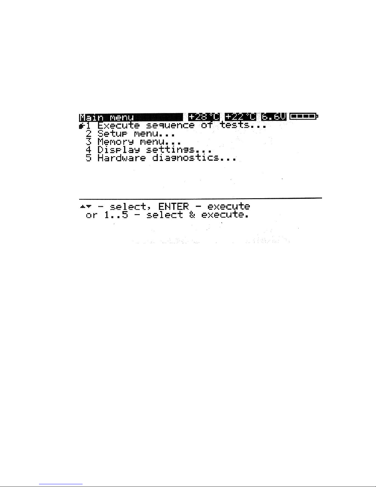
All settings and Tester operation control are performed using a set of on-screen menus.
Figure 5 shows the main menu.
ATTENTION! All setting modifications are valid only until the Tester is
switched off. To save modifications, execute “Main menu” −> “2 Setup
menu…” −> “8 Save settings”.
Figure 5
The upper screen line is the status line which displays (from left to right):
the current menu name;
the internal temperature of the Tester housing;
the temperature of the remote temperature sensor or question-marks when the
sensor is not connected;
voltage across the built-in battery terminals;
symbolic representation of a battery and the state of charge of the built-in battery.
Readings in the status line are updated every 10 seconds. Pressing the “0” button will
cause force update of the status line and checking of the remote temperature sensor
connection.
Pressing the “MEMORY” button is similar to execution of “Main menu” −> “3 Memory
menu…” −> “2 Memory usage” sequence, during which the number of entries contained
in the memory and the number of entries that can be additionally stored in the memory
are displayed.
The bottom portion of the screen under the separator bar presents information on the
activities that can be carried out using the current menu.
11

Sib Geofiz Pribor Ltd
The middle portion of the screen accommodates the lines of menu options. The left
column shows the menu active option pointer , i.e. the pointer of the option that will
be executed upon pressing the “ENTER” button. The menu options are numbered by
digits from 1 to 9.
The required menu option can be executed in two different ways:
select the desired menu option using the UP and DOWN pointing buttons and press
the ENTER button; or
press the digit button corresponding to the desired menu option.
Ellipsis at the end of the menu option name means that execution of this option will call
a submenu of the next level menu on the screen. Execution of a menu option without
ellipsis will cause immediate action specified by the option name.
Pressing the ESC button causes return to the previous level menu.
Some menus are designed to enter digital or other parameters. Hereafter, such menus
will be called “dialogue menus”. Each dialogue menu option has a related parameter,
the value of which is displayed at the end of the respective line. Parameters can be
presented by a numerical value (numerical parameter) or a mnemonic symbol, for
example, “On/Off” (mnemonic parameter).
The numerical parameter value can be modified using two methods:
pressing the LEFT or RIGHT pointing buttons will increment or decrement the value
of parameter, which corresponds to the active line, by one step. The active line
means the menu line marked with the pointer on the left;
pressing the ENTER button (or the menu option digital button) in the bottom portion
of the screen will display the permissible values of parameter and a blinking cursor
line for entering a number instead of information on this menu. Enter the desired
number using digital buttons. Pressing the LEFT button will delete the last entered
symbol, pressing the ESC button will cancel the entry. Once the number is entered,
press the ENTER button to replace the parameter value with a new one.
The mnemonic parameter value can be modified using the first of above methods only.
12
Sib Geofiz Pribor Ltd
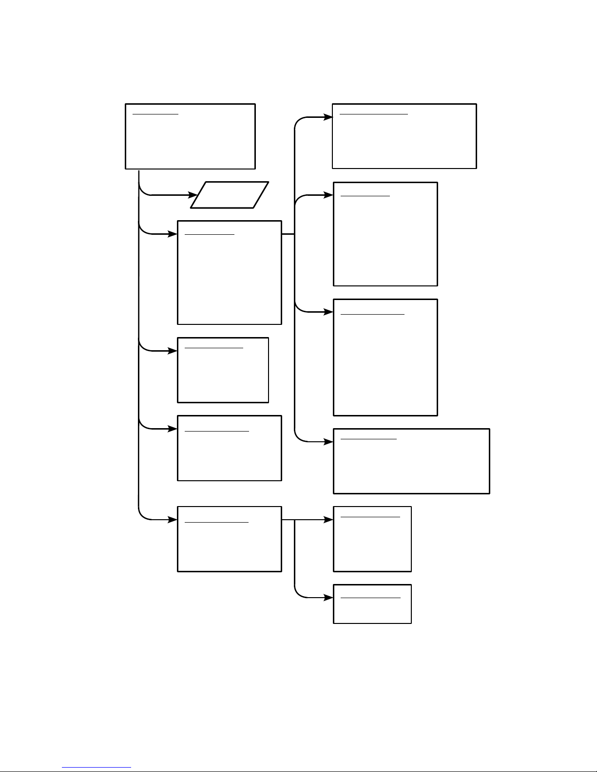
4.4. Menu Structure
The Tester menu structure is shown in Fig. 6. Below are presented detailed descriptions
of each item.
13
Main menu
1 Execute sequence of tests...
2 Setup menu...
3 Memory menu...
4 Display settings...
5 Hardware diagnostics...
Testing
Setup menu
1 Geophone menu...
2 String menu...
3 Sequence of tests...
4 Operation condition...
5 Date & time...
6 Default settings
7 Read settings
8 Save settings
Geophone menu
1 Select type...
2 New copy of selected type
3 Edit selected type...
4 Delete selected type
5 Delete all types added by user
2
1
Memory menu
1 Display last file
2 Memory usage
3 List files
4 Upload files
5 Erase all files
3
Display settings
1 Backlight brightness:
2 Backlight OFF time:
3 LCD contrast:
4 Key beeps:
4
HW diagnostics
1 Display...
2 Sine wave generator...
3 Self-test
4 Power
String menu
1 String number:
2 Series:
3 Parallel:
4 Cable resistance:
5 Interval:
6 Lead-in cable length:
7 Presence of shunts:
8 Shunt resistance:
Tests sequence
1 Polarity:
2 Noise:
3 Leakage:
4 Resistance:
5 Natural frequency:
6 Damping:
7 Sensitivity:
8 Distortion:
9 Impedance:
Op conditions
1 Autoincrement of string number:
2 Continue test on reject:
3 Save test data on reject:
4 String temperature:
5 Polarity test:
5
Display testing
1 Screen
2 Backlight
3 Contrast
4 Keypad
5 Sound
Sine generator
1 Frequency:
2 Amplitude:
Testing
1
2
3
4
1
2
Figure 6
Sib Geofiz Pribor Ltd
4.4.1. Setup menu… - Geophone menu
The “Geophone menu” is intended to manage the geophone library and to select the
geophone type, the parameters of which will be used as a reference for further work.
The Tester memory accommodates a library containing geophone reference data. The
library is divided in two parts: read-only and variable libraries.
The read-only library is stored in the memory portion protected against cancellation and
modification. It holds data corresponding to the rated values published by the
manufacturer of a respective geophone. The read-only library will be expanded as the
Tester built-in firmware versions are updated.
The variable library is accessible for modification by the User. The variable library can
hold data on 30 geophones as a maximum. The total number of geophones in the
libraries cannot exceed 99.
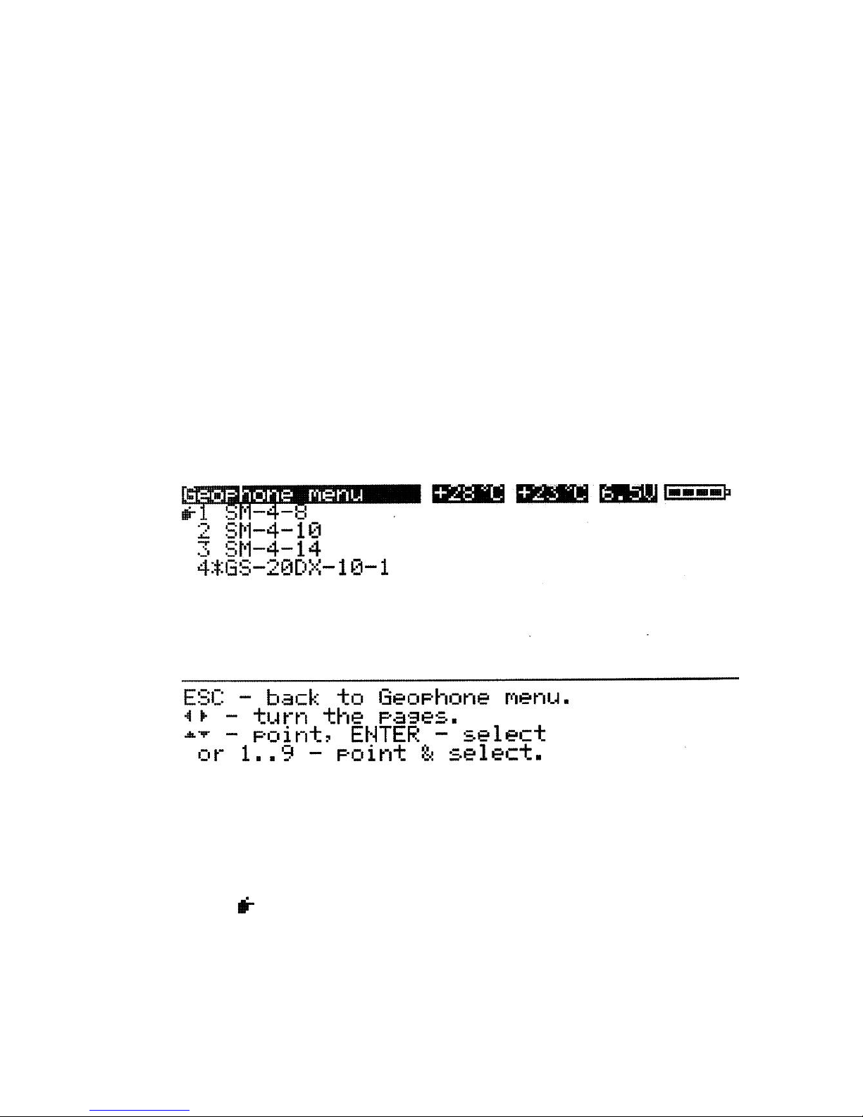
4.4.1.1. Select type…
When this option is executed, the list of geophones, the data on which are available in
the Tester libraries, is displayed on the screen. The display process starts from the
page containing the entry of the currently selected geophone. Geophones from the
variable library are marked with the * character (see Figure 7).
Figure 7
Line 4 in the presented screen shot correspond to the geophone type created by the
User.
The pointer is represented at the beginning of the line corresponding to the selected
geophone. A list that is too big for the screen can be paged by pressing the LEFT and
RIGHT buttons. One page can accommodate 9 lines. To select a geophone, move the
pointer to the desired line using the UP, DOWN, LEFT and RIGHT buttons, and press
14
 Loading...