

Siberian Cyber iCTABLE, iCTABLE Pro User Manual
Stage - Frame
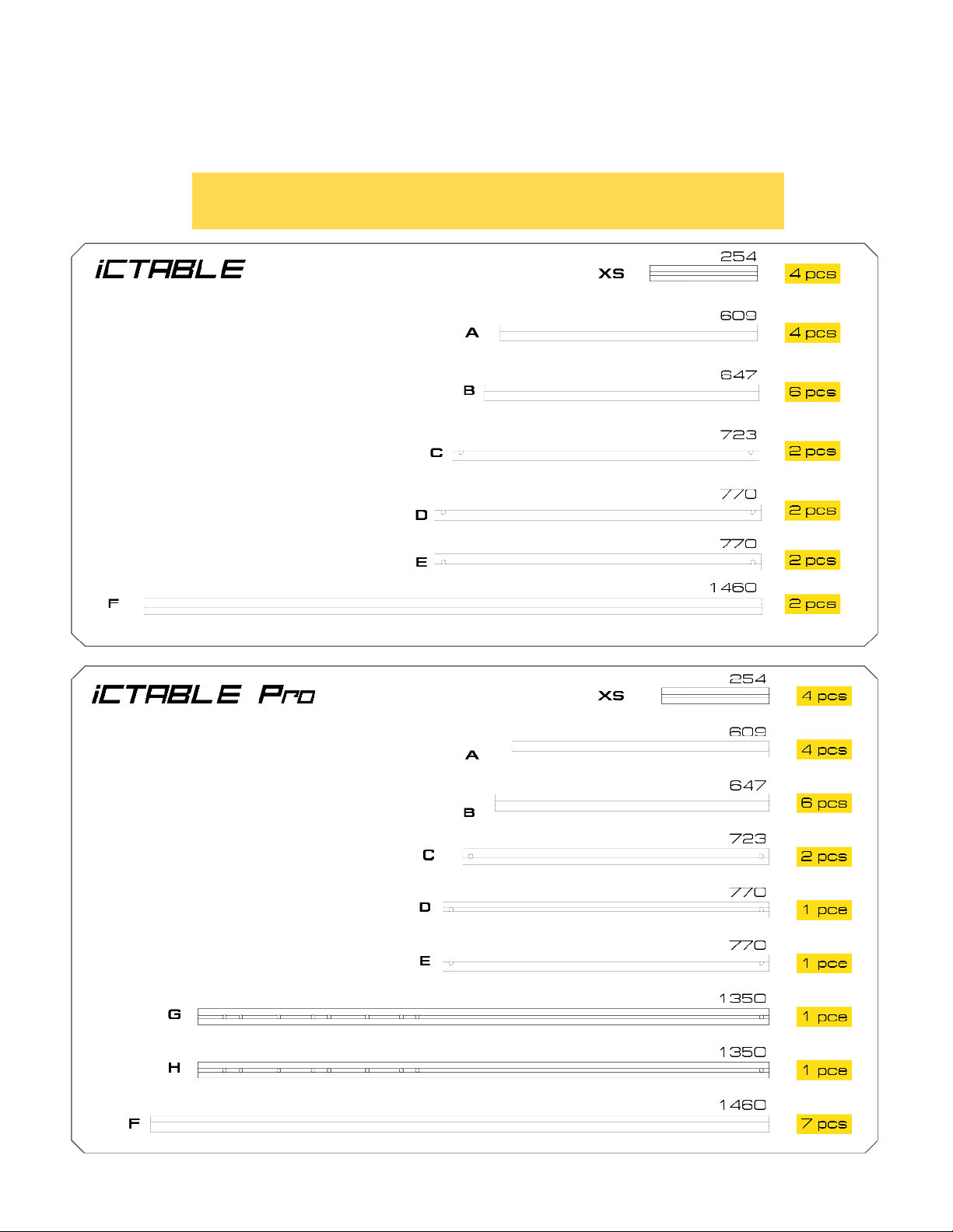
iCTABLE
Frame Assembly
Profile Chart
Frame Box Part 1
Page 1
iCTABLE Manual
Siberian Cyber, Inc.
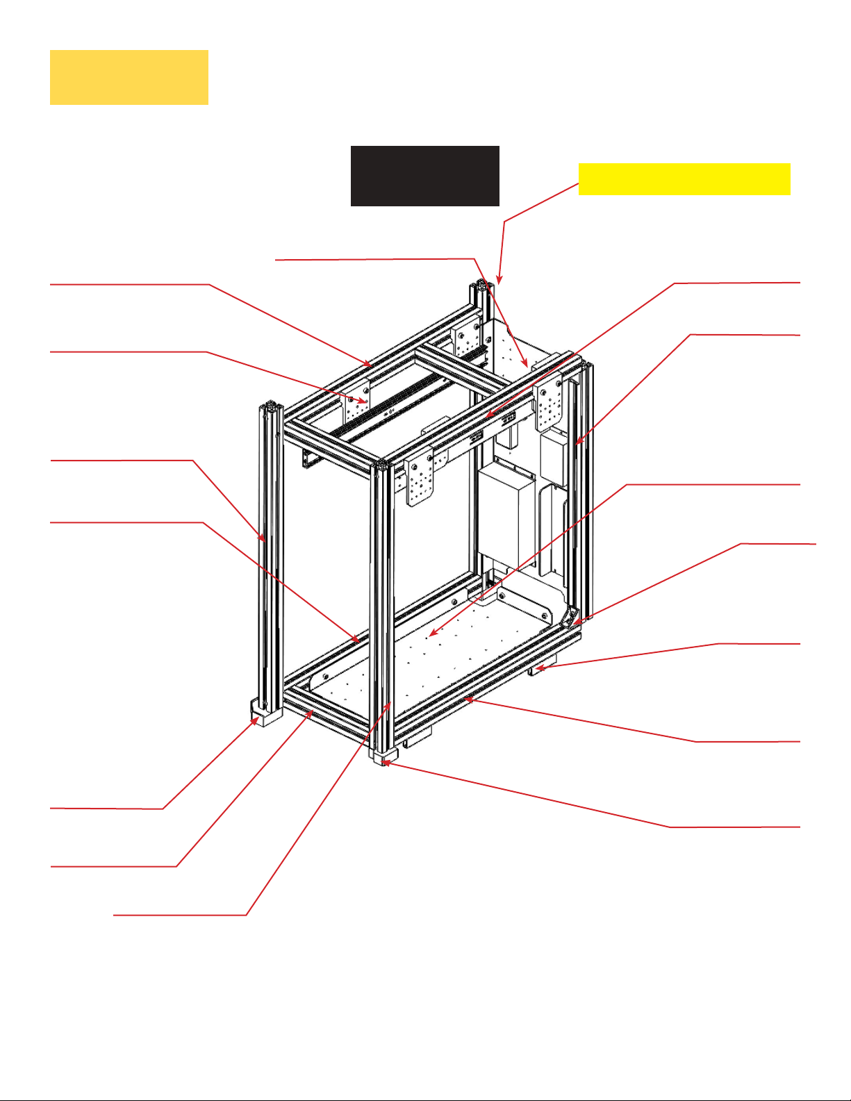
Stage - Frame
Overview
B -Profile (647)
ACC -Holder
E -Profile LEFT
iCTABLE
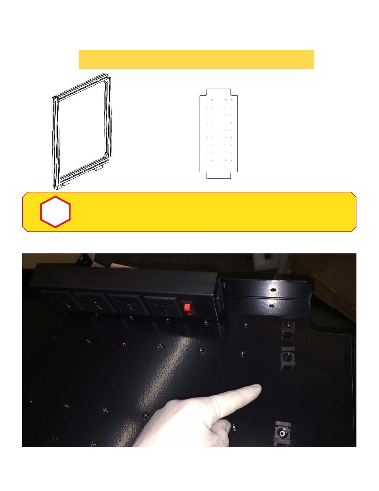
Frame Box Structure
LEFT
P -Vertical Box Panel
H -Profile (1350) - PRO
A -Profile (609)
B -Profile (647)
O -Bottom Box Panel
B -Profile (647)
Corner Leg
XS Profile
C Profile (723)
Corner Connector
Support Leg
A -Profile (609)
Inner Leg (Left)
Frame Box Part 1
Page 2
iCTABLE Manual
Siberian Cyber, Inc.
Overview
Inner Leg (Right)
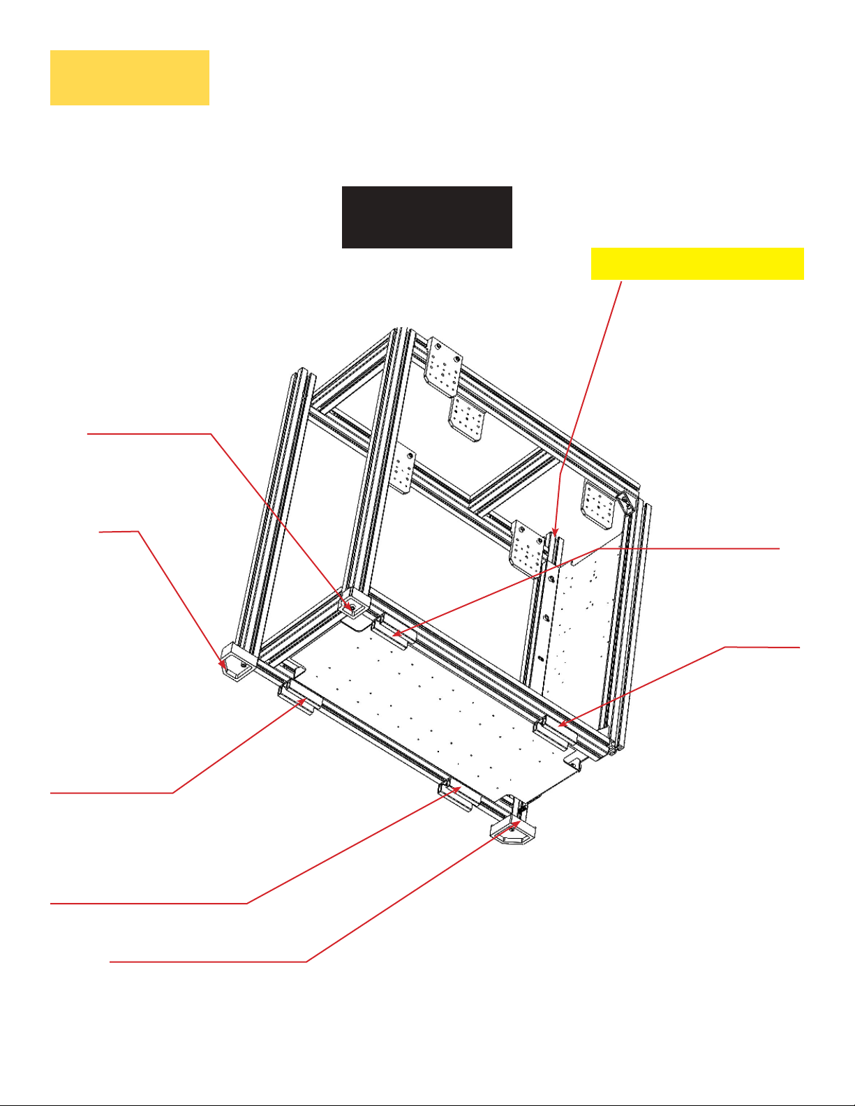
Stage - Frame
iCTABLE
Legs Position
LEFT
H -Profile (1350) - PRO
Corner Leg
Support Leg
Support Leg
Support Leg
Support Leg
Corner Leg
Frame Box Part 1
Page 3
iCTABLE Manual
Siberian Cyber, Inc.
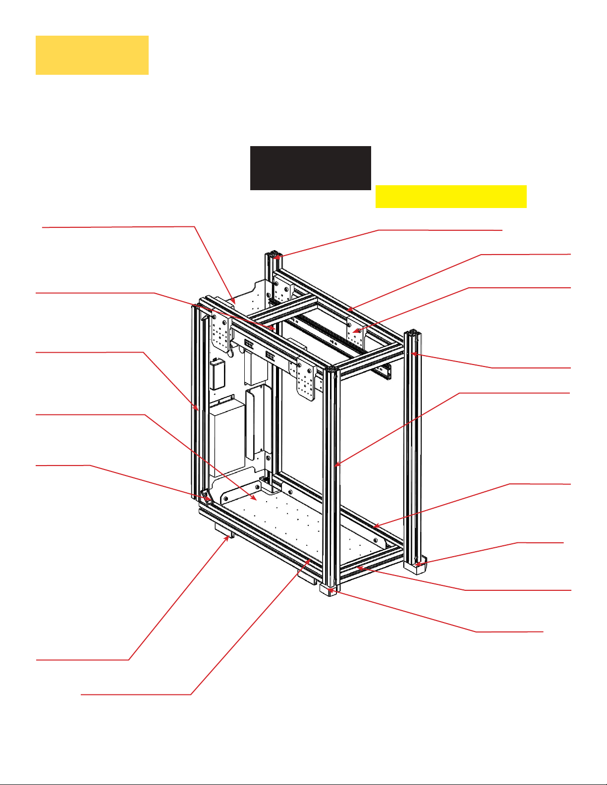
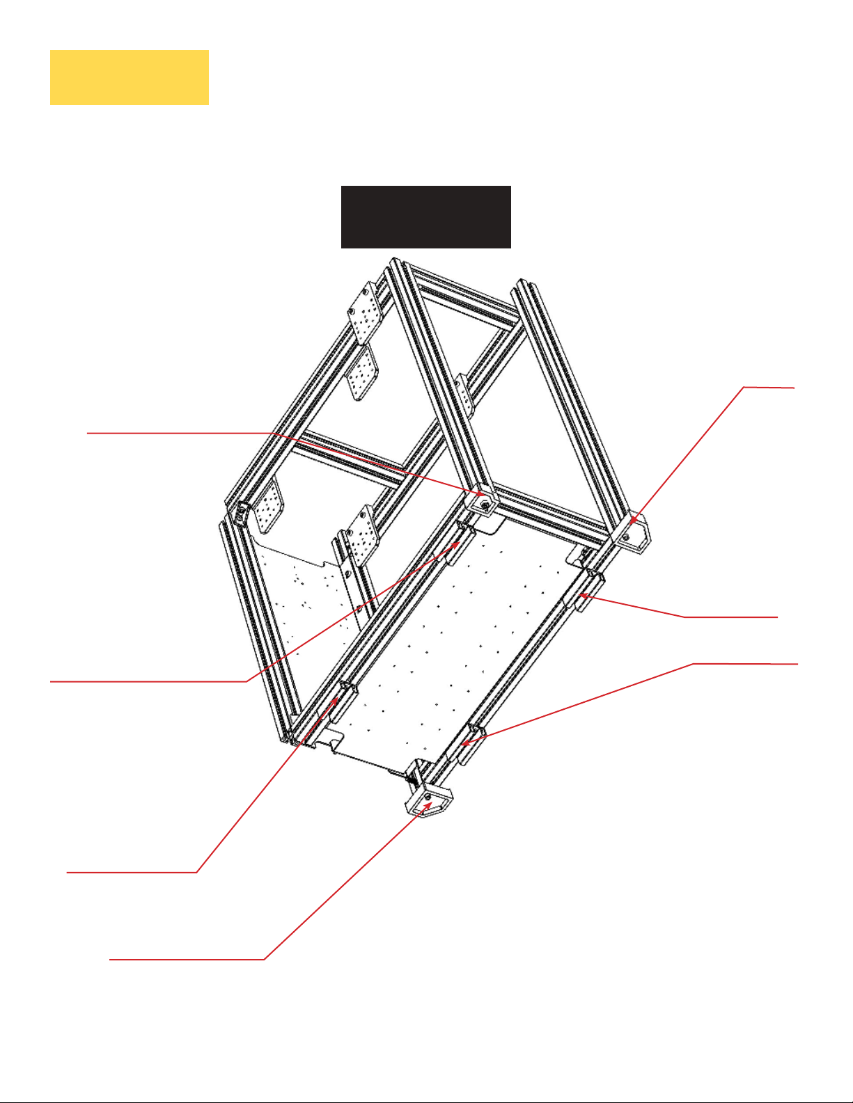
Overview
Stage - Frame
iCTABLE
Frame Box Structure
RIGHT
G -Profile (1350) - PRO
P -Vertical Box Panel
A -Profile (609)
B -Profile (647)
O -Bottom Box Panel
Corner Connector
D -Profile RIGHT (770)
B -Profile (647)
ACC -Holder
D -Profile RIGHT (770)
C Profile (723)
B -Profile (647)
Support Leg
A -Profile (609)
Frame Box Part 1
Page 4
iCTABLE Manual
Corner Leg
XS Profile
Inner Leg (Right)
Siberian Cyber, Inc.
Overview
Inner Leg (Right)
Stage - Frame
iCTABLE
Legs Position
RIGHT
Corner Leg
Support Leg
Support Leg
Corner Leg
Support Leg
Support Leg
Corner Leg
Frame Box Part 1
Page 5
iCTABLE Manual
Siberian Cyber, Inc.
H -Profile (1350) - PRO
Stage - Frame
iCTABLE
Inner Side
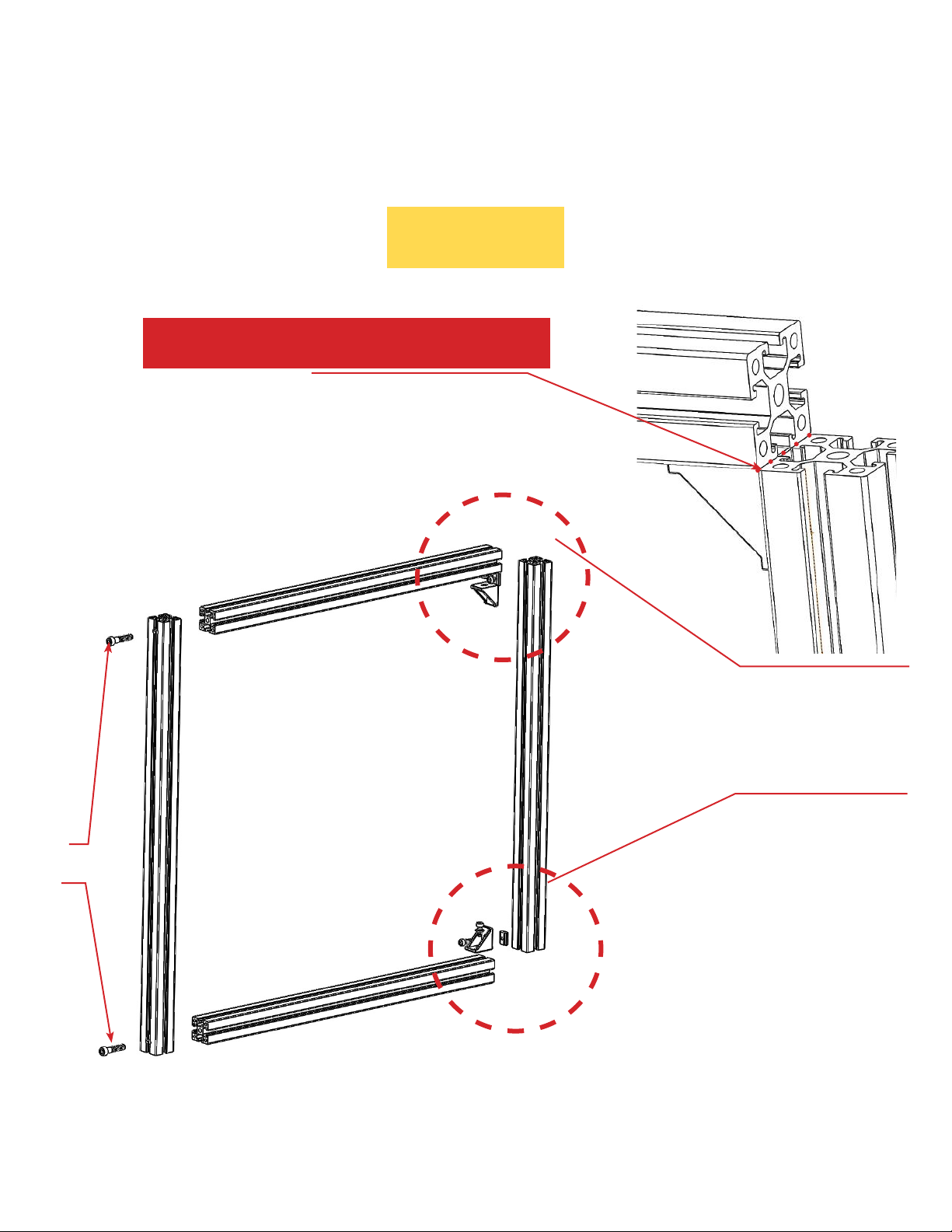
Frame Assembly
Steps
1
A -Profile (609)
NO Thread
2
3
B -Profile (647)
C Profile (723)
A -Profile (609)
C Profile (723)
C Profile (723)
4
Same Steps for the Right Box
Frame Box Part 1
Page 6
iCTABLE Manual
Thread
Siberian Cyber, Inc.
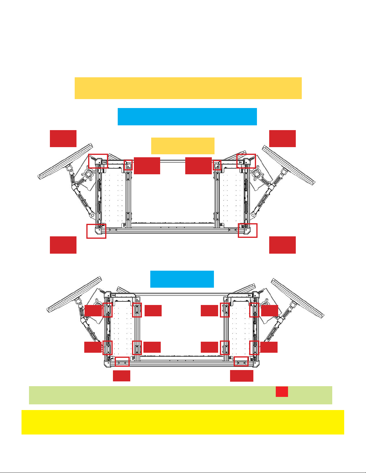
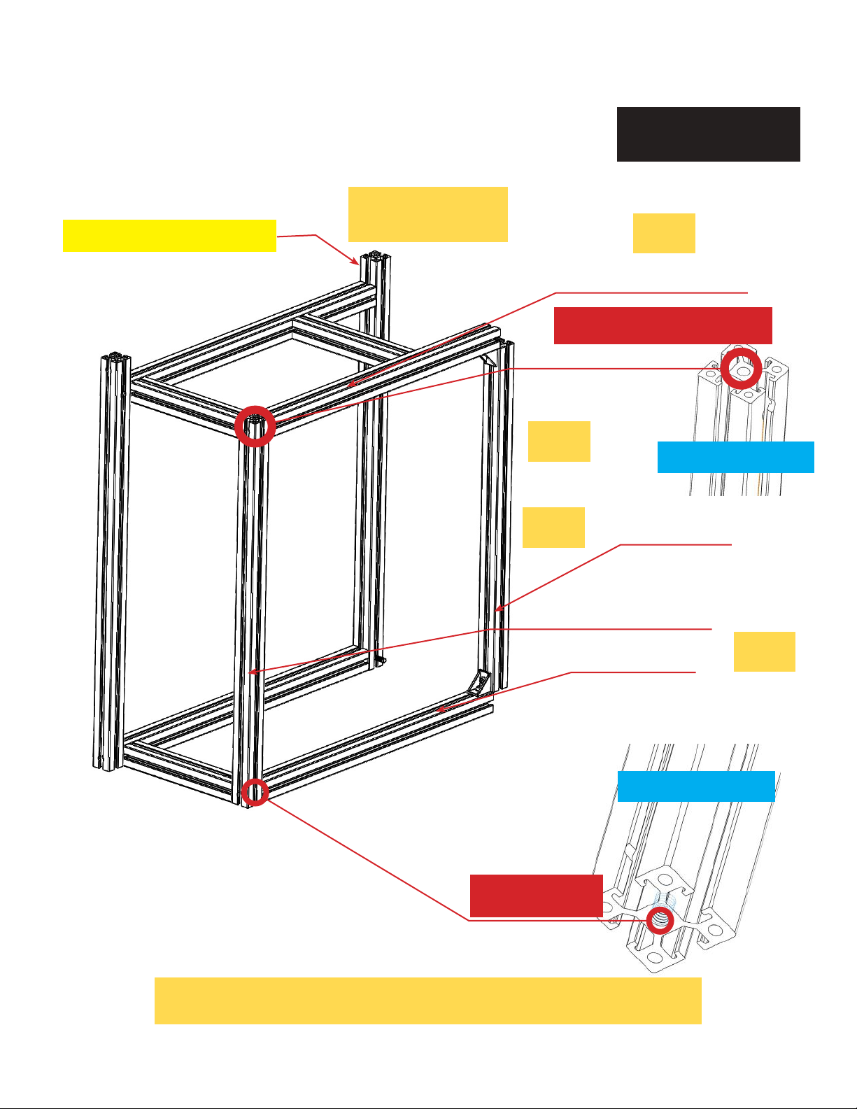
Stage - Frame
iCTABLE
Frame Assembly
Corner Legs and Support Legs
Bottom View
1
3
1
Corner Legs
5 6
Support Legs
2
2
4
5 6
3
4
7 8
9 10
The Outside Legs, Inside Legs, and the Support Legs create 16 fulcrums
that ensure the stability of iCTABLE
Important: iCTABLE should be placed on a flat and hard surface to exclude
any potential instability and unbalance in its construction.
Page 7
Frame Box Part 1
iCTABLE Manual
16
Siberian Cyber, Inc.
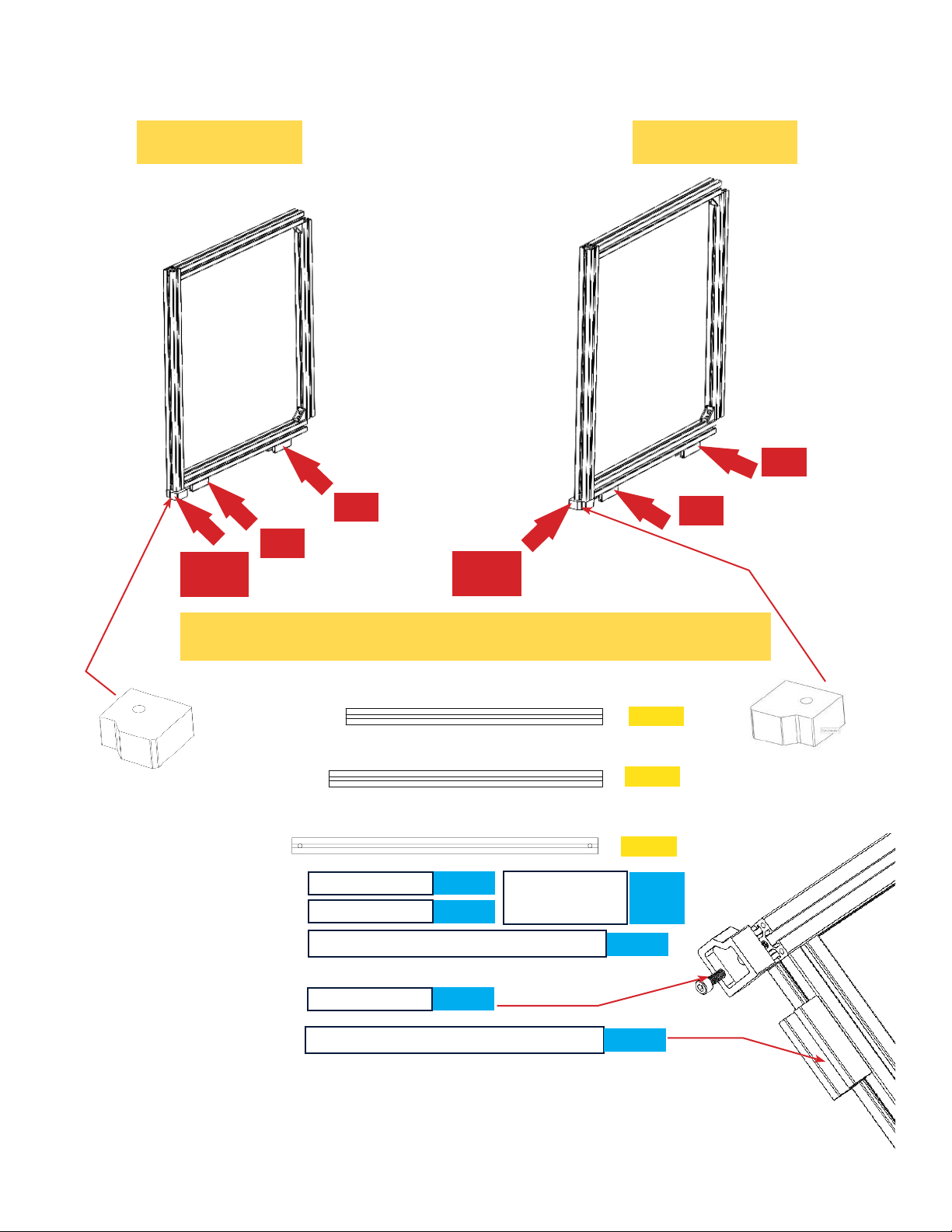
Stage - Frame
Left Box Assembly Steps
For Left Box For Right Box
C
A
A
5
2
B
C
4
6
Components
A
B
A
7
5
A
B
C
M6 16
Spring Nut
L-Corner Connector
M8 20
Support Leg
723
2 pcs
2 pcs
2 pcs
Page 8
609
647
Head Bolt
Washer
4 pcs
2 pcs
2 pcs
2
pcs
1 pce
4 pcs
TKONS
iCTABLE Manual
Siberian Cyber, Inc.
Stage - Frame
iCTABLE
Frame Assembly
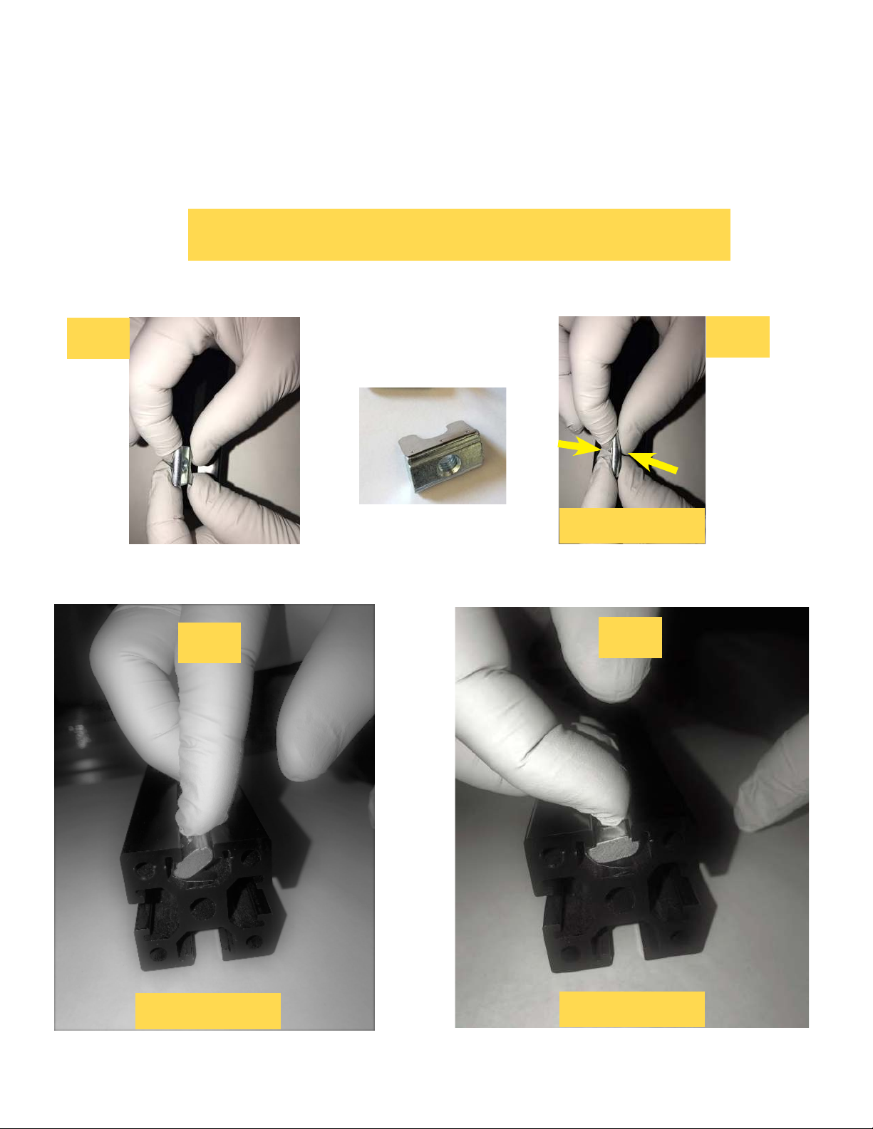
How It Works
1
3
Spring Nut
2
Press
4
Insert
Frame Box Part 1
Page 9
iCTABLE Manual
Adjust
Siberian Cyber, Inc.
iCTABLE
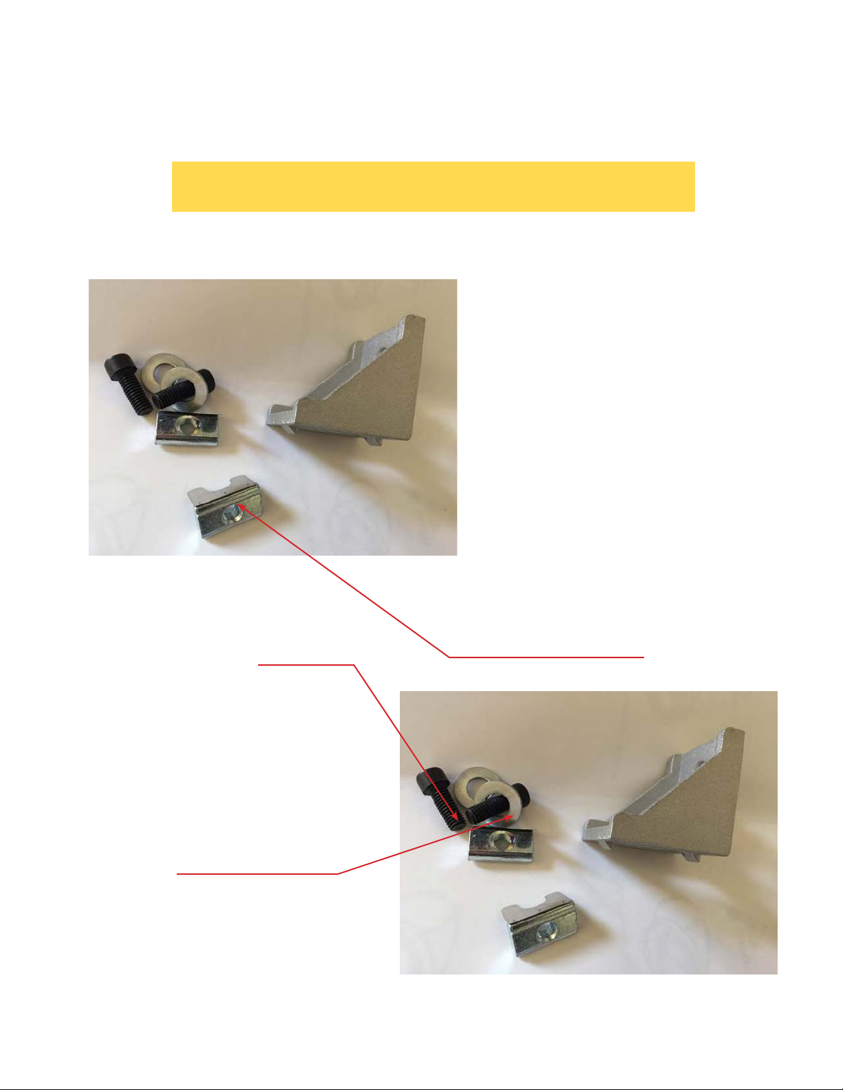
Frame Assembly
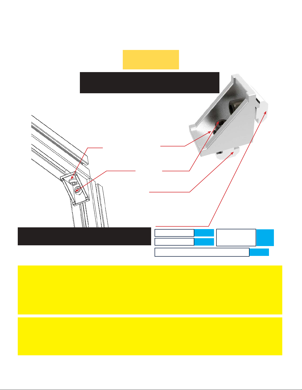
Details
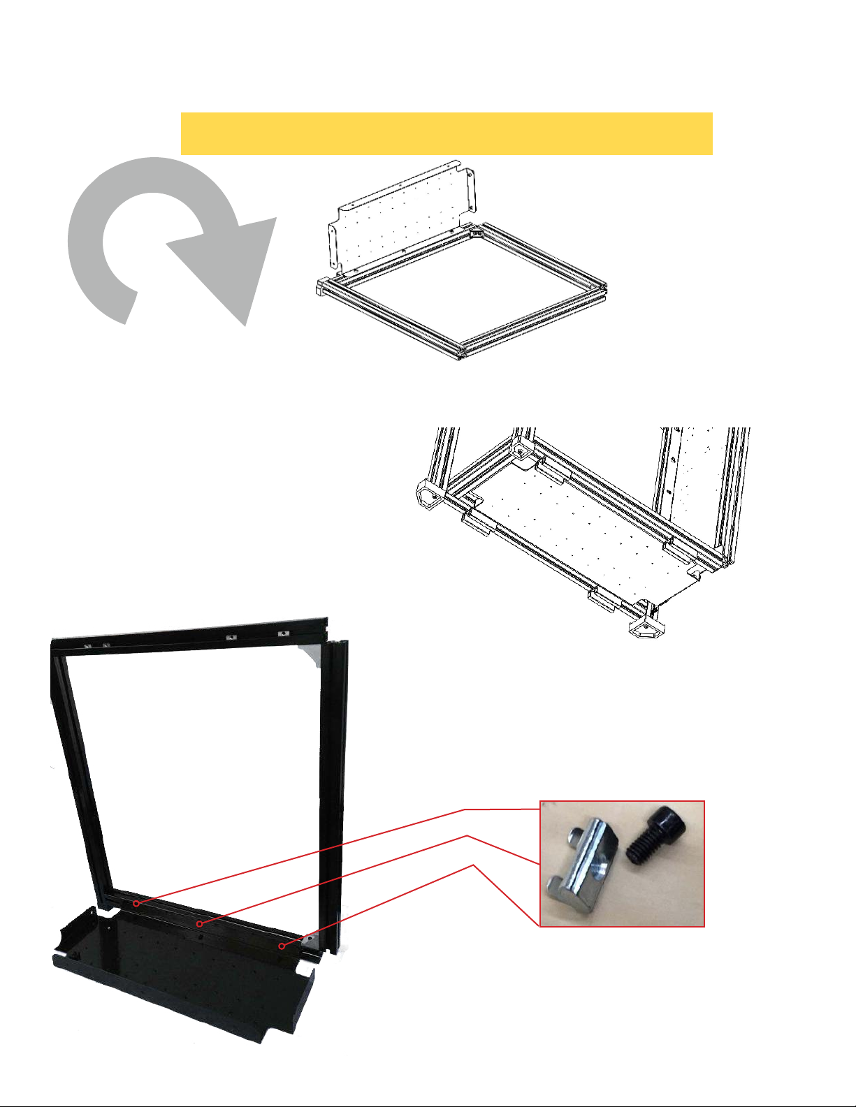
Corner CONNECTOR
Head Bolt Washer
M6 16
SPRING NUT
SPRING NUT
Corner CONNECTOR SET
M6 16
Spring Nut
L-Corner Connector
Note: When putting in the Spring Nut, squeeze the spring and insert into
the identified position so the Spring Nut pops in and becomes static. Important: When screwing in M6 screws into the Spring Nut, try not to apply
pressure but simply rotating it in. Otherwise, it is possible that the Spring
Nut will pop off.
Important: When screwing in M6 screws into the Spring Nut, try not to
apply pressure but simply rotating it in. Otherwise, it is possible that the
Spring Nut will pop off
.
2 pcs
2 pcs
Head Bolt
Washer
2
pcs
1 pce
Frame Box Part 1
Page 10
iCTABLE Manual
Siberian Cyber, Inc.
Stage - Frame
iCTABLE
Frame Assembly
Details
Corner-To-Corner
M8 35
Frame Box Part 1
Page 11
iCTABLE Manual
Siberian Cyber, Inc.
Stage - Frame
iCTABLE
Frame Assembly
Pictures of components
M6 16
Head Bolt Washer
SPRING NUT
Page 12
Frame Box Part 1
iCTABLE Manual
Siberian Cyber, Inc.

Stage - Frame
iCTABLE
Frame Assembly
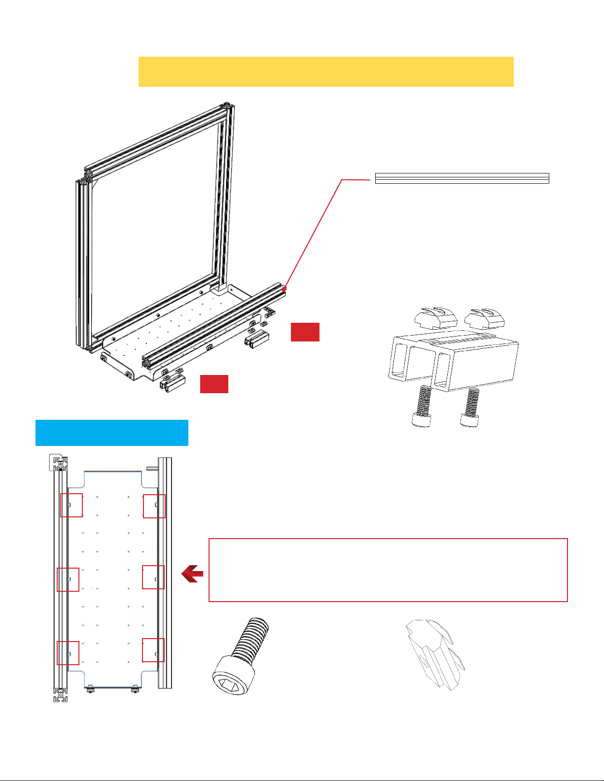
Support Leg Assembly
Support Leg
Components of SET
M6 10 Socket Head
Cap Screw
2 pcs
Spring Nut
2 pcs
For iCTABLE/iCTABLE Pro - 10
Frame Box Part 1
Sets!
Page 13
iCTABLE Manual
Siberian Cyber, Inc.
Stage - Frame
Left Box Assembly Steps
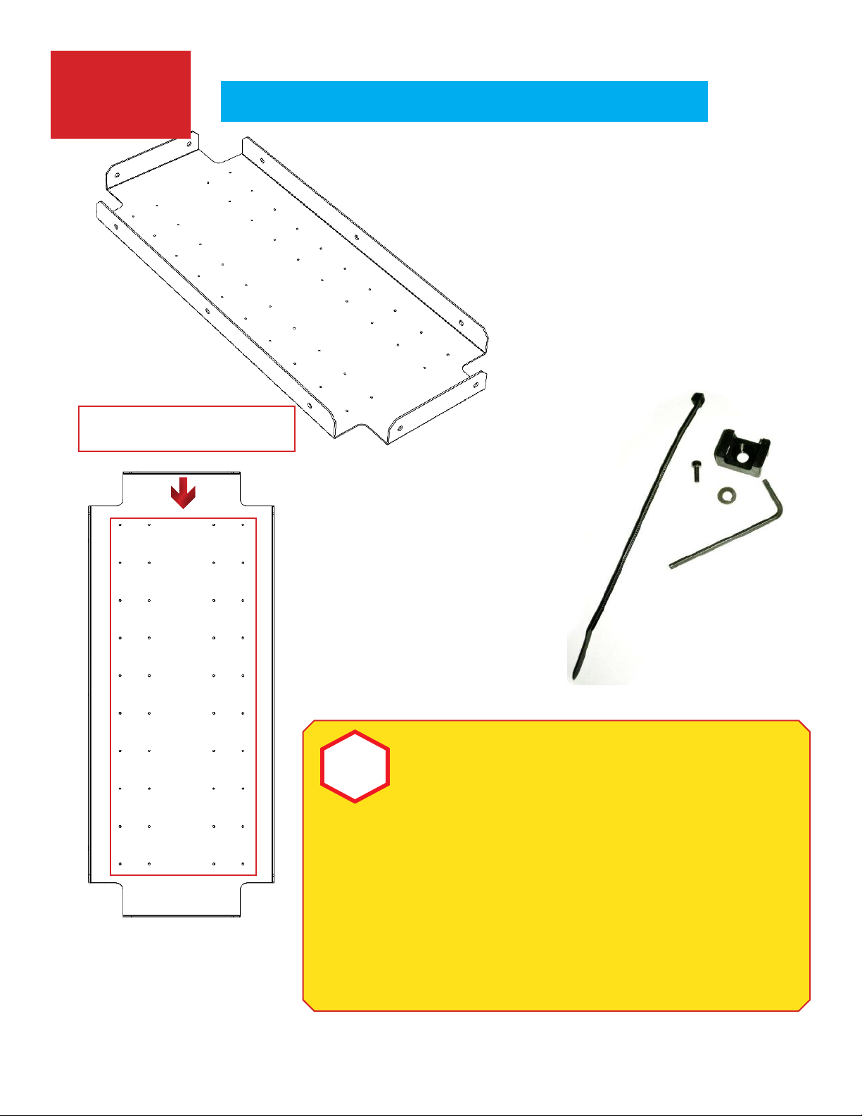
Bottom Level Assembly
O
!
+
Time to preparing wire clips
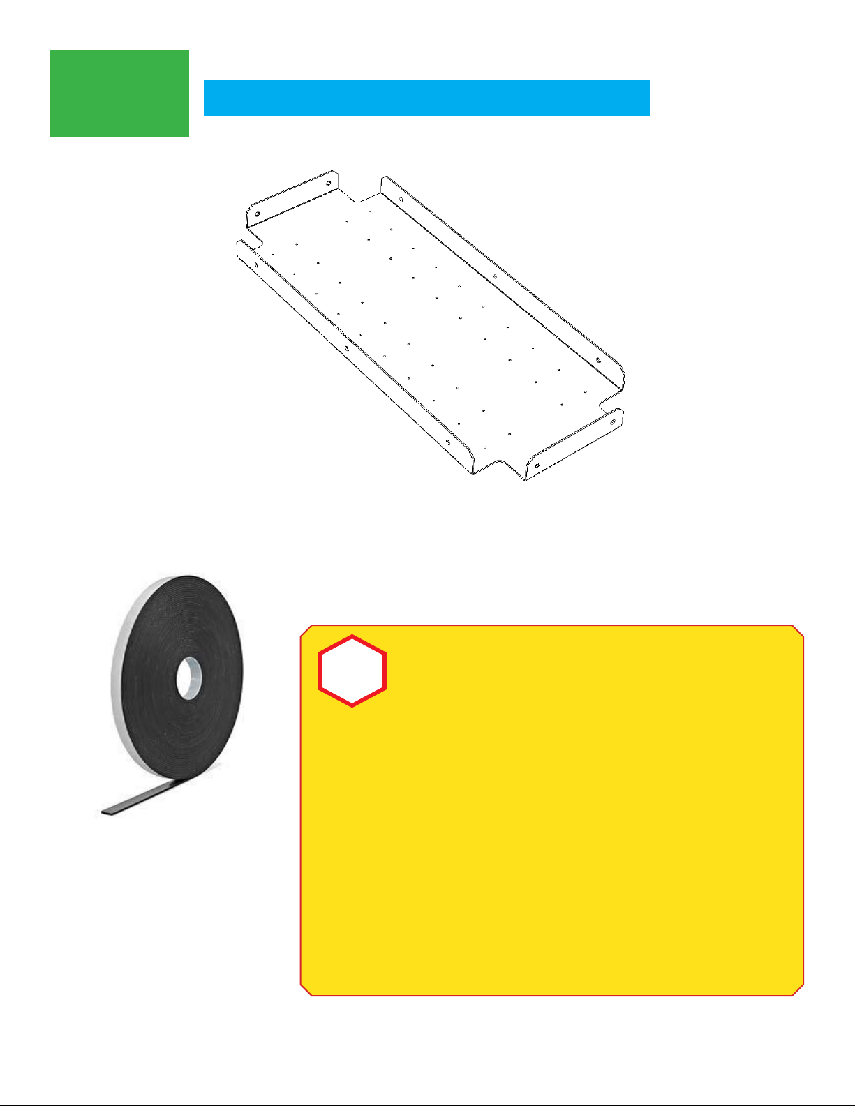
Bottom Box Panel
Frame Box Part 1
Page 14
iCTABLE Manual
Siberian Cyber, Inc.
Stage - Frame
Left Box Assembly Steps
Bottom Level Assembly
Frame Box Part 1
Page 15
iCTABLE Manual
Siberian Cyber, Inc.
Left Box Assembly Steps
Box-Bottom Level
Top View
3
+
1
B
647
+
SUPPOPRT LEG - 2
SETS
Frame Box Part 1
+
M6 10 Socket Head Cap
Screw+Spring Nuts
6 pcs
Page 16
iCTABLE Manual
Siberian Cyber, Inc.
6 pcs
Left Box Assembly Steps
Screws
Mounting
M3 Threads
Box-Bottom Level
Bottom Box Panel
O
Frame Box Part 1
!
iCTABLE Manual
Be advised that during the
installation process, the screws
might not go in easily. If this occurs,
gradually apply more force, while
swiveling the screw back and
forth until it goes all the way in. In
addition, you may use WD-40 or
comparable lubricant to ease the
installation process.clips
Page 17
Siberian Cyber, Inc.
Screwless-
Mounting
O
Bottom Box Panel
Left Box Assembly Steps
Box-Bottom Level
Frame Box Part 1
When mounting additional
!
iCTABLE Manual
components to the surface
of the panel, without using the
screws, we recommend using
Heavy Duty Double-Sided Foam
Tape. Before applying the tape,
take care to prepare and clean
the surface of the panel, using
medicinal alcohol or equivalent
cleaning agent. Please remain
careful when using any cleaning
agent and comply with the safety
regulations advised by the
product producer.
Page 18
Siberian Cyber, Inc.
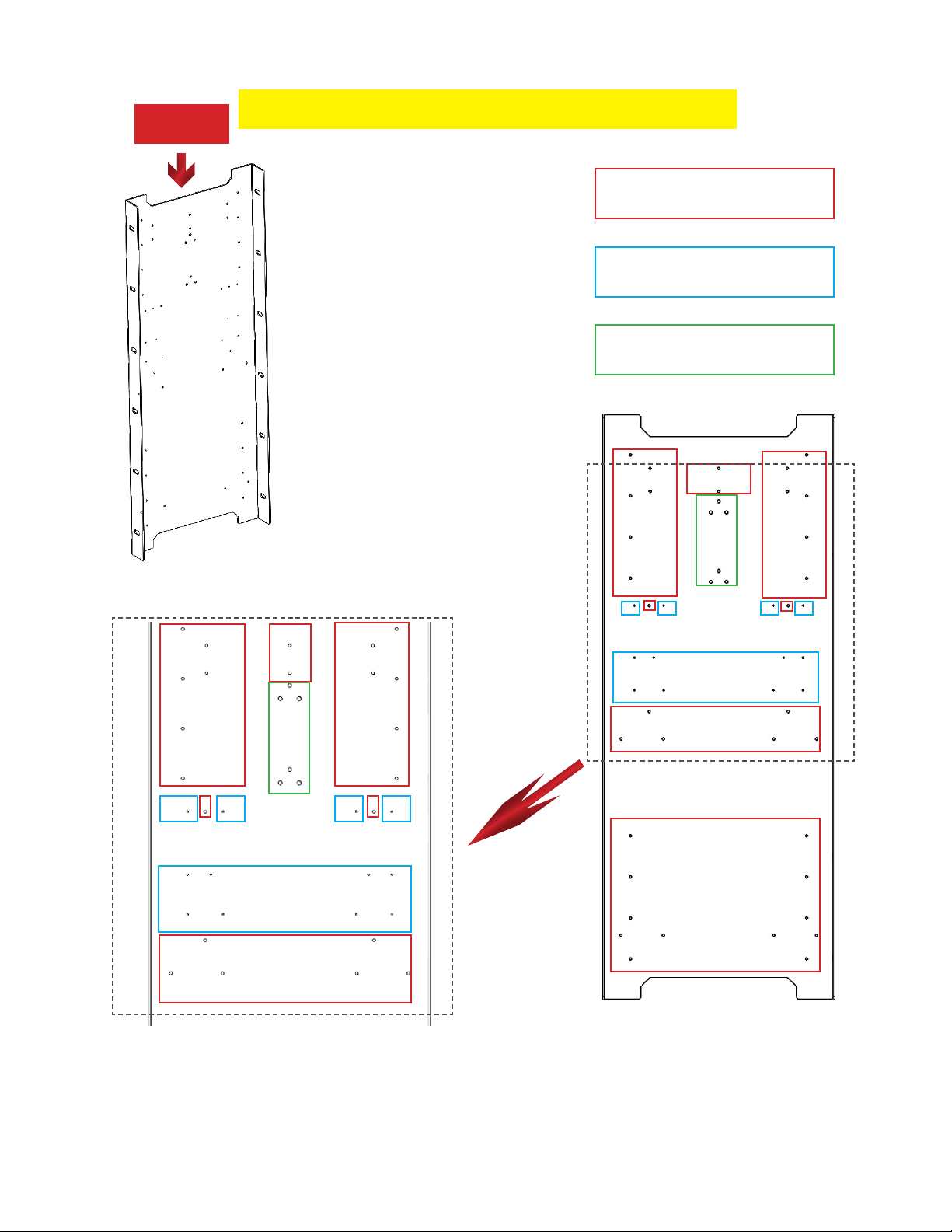
Left Box Assembly Steps
TOP
Vertical Panel
P
Vertical Box Panel
M3 Threads
M2 Threads
M4 Threads
Frame Box Part 1
Page 19
iCTABLE Manual
Siberian Cyber, Inc.
 Loading...