

SIATA AQUA IONIC User And Maintenance Manual

Aqua Ionic - 1 di 24
AQUA IONIC
USER’S AND MAINTENANCE
MANUAL
y:Distributed b
37 Tannery Lane
#06-08 Tannery House
Singapore 347790
Tel: +65 6741 2994 • Fax: +65 6741 2995
S.I.A.T.A Asia Pacific Pte Ltd
Distributed by:
www.siata.com.sg
Aqua Ionic - 2 di 24
EC DECLARATION OF CONFORMITY
Manufacturer S.I.A.T.A. S.r.l.
Herewith declares that:
PN
AJ7-02/05
Description
AQUA JONIC CONTROLLER WITH PROBE
is in conformity with the provision of the following EEC directives:
Elettromagnetic Compatibilty 89/336/EEC, 93/68/EEC
Low Voltage 73/23/EEC,93/68/EEC
and that the following harmonized standards have been applied:
EN 50081-1 Generic Emission Standard-Part 1:residential,commercial and light
industrial premises.
EN 50082-1 Generic Immunity Standard-Part 1:residential,commercial and light
industrial premises.
EN 60742 Directions concerning isolation and security trasformers.
S.I.A.T.A. S.r.l. has a quality system in accordance with the requirements of
ISO 9001/ UNI EN ISO 9001-ed.1994 (Certificate n° 95.022 SGS ICS)
Managing Director
LUIGI FERRALI
TEN0044.doc

Aqua Ionic - 3 di 24
Table of contents
1 – GENERAL CHARACTERISTICS ..................................................................... 4
2 – TECHNICAL DATA ............................................................................................ 4
4 – CODE MEANING ................................................................................................. 7
5 - GENERAL INFORMATION ............................................................................... 8
5.1 – Packaging and storage ........................................................................................................... 8
5.2 – Installation .............................................................................................................................. 8
5.3 – Maintenance ........................................................................................................................... 9
5.4 – Safety devices ......................................................................................................................... 9
6 – INSTRUCTIONS FOR USE .............................................................................. 10
6.1 – Powering on .......................................................................................................................... 10
6.2 – Working ................................................................................................................................ 10
6.2.1 – Auto Set Point ................................................................................................................. 11
6.2.2 – Auto Volume ................................................................................................................... 12
6.2.3 – Auto Set Point + Auto Volume ....................................................................................... 12
6.2.4 – Manual ............................................................................................................................. 12
6.2.5 – Auto Set point + Manual ................................................................................................. 12
6.2.6 – Auto Volume + Manual ................................................................................................... 13
6.3 – Checking the regeneration efficiency ................................................................................. 13
6.4 – Programming ....................................................................................................................... 14
6.5 – Starting operations .............................................................................................................. 15
6.6 – Managing the volume .......................................................................................................... 15
6.7 – Installing the probe. ............................................................................................................. 16
6.8 – Connections .......................................................................................................................... 17
6.8.1 – Connection of this version to 3 DIN sockets ................................................................... 18
7 – TROUBLESHOOTING ...................................................................................... 19
8 – SPARE PARTS .................................................................................................... 21

Aqua Ionic - 4 di 24
1 – GENERAL CHARACTERISTICS
Aqua Ionic manages SIATA multi-way valves for the creation of water treatment devices.
The regenerative cycle, which is completely programmable, can be activated in either of the
following ways:
after a programmable time during which the probe detects that the water is not good;
immediately when the treatable volume is exhausted;
manually, using the Manual Regen key;
immediately by means of the Remote Start external signal.
Aqua Ionic is provided with an eeprom memory where the programming is stored, and of a buffer
battery allowing to keep the working parameters in the memory in the event of a supply voltage
failure.
Aqua Ionic, as well as all the other SIATA controllers, is compliant with the EEC Directives and is
built in the SIATA factory in Montespertoli, Florence (Italy) working with the Quality System
certified according to the following standard
ISO 9001 / UNI EN ISO 9001.
2 – TECHNICAL DATA
Supply voltage 230 Vac 10% (*)
Mains frequency 50 Hz 3% (*)
Absorbed power 4.6 VA
Working temperature 4° C – 40° C
Case size 165 mm x 127 mm x 70 mm
Total weight from 1 to 1.7 Kg
(*) Special versions available upon request.
Aqua Ionic - 5 di 24
3 – MEANING OF LEDs AND KEYS
LED functionality (Tab. 1)
SET POINT
(yellow case)
It is on during the set point value setting.
SET POINT
(blue case)
It is on when the conductivity value surpasses the set point value.
ALARM (blue case)
SET POINT DELAY
(yellow case)
It goes on during programming when setting the set point intervention time.
During operation, it illuminates to indicate an alarm condition.
EXT. ALARM
It is on when the inhibition signal is present.
AUTO SET POINT
It is on when the regeneration must start because water is not good.
AUTO VOLUME
It is on when the regeneration must start because of exhausted volume.
MANUAL
It is on when the regeneration must not start automatically.
INT. ALARM
It is on when regeneration is not successful.
Fig. 1
Aqua Ionic - 6 di 24
Key functionality (Tab. 2)
X 0.1
When pressed during operation, it changes the setting of the X 1 or X 10 probes.
When pressed at the end of the programming phase, it allows to access the
programming of the regeneration cycle phases.
PROGRAM
MODE
It allows to access the programming functions of the working parameters.
ADVANCE
When pressed during programming or time setting, it allows to increase the digit
blinking on the display.
When pressed during operation, it allows to display the residual volume.
SELECT
It allows to change the regeneration start mode.
MAN. REGEN
It allows to activate the regeneration manually.
RESET
During programming, it allows to quit without saving the parameter being
modified when the key is pressed.
During regeneration it ends it.
HIDDEN KEY
Placed below the 6 keys, in the middle between Advance and Volume/Clock, it
allows to start a test regeneration. When pressed during some programming
phases, it zeroes the digit blinking on the display.
Aqua Ionic - 7 di 24
4 – CODE MEANING
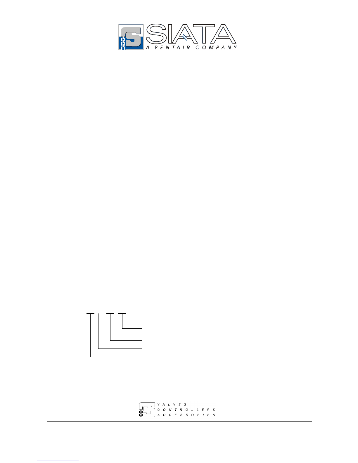
On the case rear panel a label as in Fig. 2 indicates:
AI7-02/05 the controller code
12705 the order number (which is the same as the lot number)
SN 110/98 the serial number with reference to the code
In particular, the controller code is composed as follows:
AI 7 – 02 / 05
Controller version, assigned by the Technical Office for
customizations (05 = standard).
Typology of the electric connections (02 = DIN sockets).
Number of drivers (7 = 7 drivers).
Family to which the controller belongs (AI = Aqua Ionic).
Fig. 2
Fig. 2

Aqua Ionic - 8 di 24
5 - GENERAL INFORMATION
Please find herewith below some instructions to be followed during the controller usage and
maintenance in order to ensure its long-term operativity.
5.1 – Packaging and storage
The package consists in a box with a product identification label.
The device must be stored in environments compliant with the following characteristics:
- temperature within +4°C e +40°C;
- relative humidity within 30 % and 95 %.
5.2 – Installation
The controller installation must be performed by qualified technical staff; the installation
procedures must be performed when the device is off power.
The device consists in an ABS case closed on front by a cover blocked with 4 screws. As an
optional, a transparent cover is available that can be used as a keyboard protection.
The controller is supplied by a 230 / 12 Vac transformer. Upon request, other types of transformer
are available (Es. 115 / 12 Vac – 60 Hz).
The right hand side of the case is opened where the DIN sockets are placed (Fig. 9).
Fig. 3
Fig. 4
 Loading...