

siat SM446 HS Instruction Manual And Spare Parts List

SM446 HS
NASTRATRICE AUTOMATICA
AUTOMATIC CASE SEALING MACHINE
MACHINE ENRUBANNEUSE AUTOMATIQUE
AUTOMATISCHE KARTONVERSCHLIESSMASCHINE
PRECINTADORA AUTOMATICA
MANUALE DI ISTRUZIONI E PARTI DI RICAMBIO
INSTRUCTIONS MANUAL AND SPARE PARTS LIST
MANUAL D’INSTRUCTIONS ET PIECES DETACHEES
BEDIENUNGSANLEITUNG UND ERSTAZTEILLISTE
MANUAL DE INSTRUCCIONES Y RECAMBIOS
Cod. pubbl.: SBC0023374
SIAT
Instruction manual for the use, maintenance, safety, shipment, storage, unpacking, set-up, repairing, trouble shooting, spare parts and disposal concerning the case sealing machine model SM446 HS.
This publication is property of SIAT S.P.A.
Via Puecher, 22 - 22078 TURATE (CO) - ITALY
Tel. 02-964951 - Fax. 02-9689727
Edition: April 2013
The reproduction of this manual is strictly forbidden.
All rights reserved ©Siat S.p.A. 2013
The manufacturer reserves the right to modify the product at any time without notice.
Publication n. SBC0023374
Version 0
S.p.A. - Via Puecher, 22 - 22078 TURATE (CO) ITALY - P.O. BOX 1
Tel. 02-964951 - Telefax 02-9689727
http://www.siat.com - E-Mail: siat@siat.com
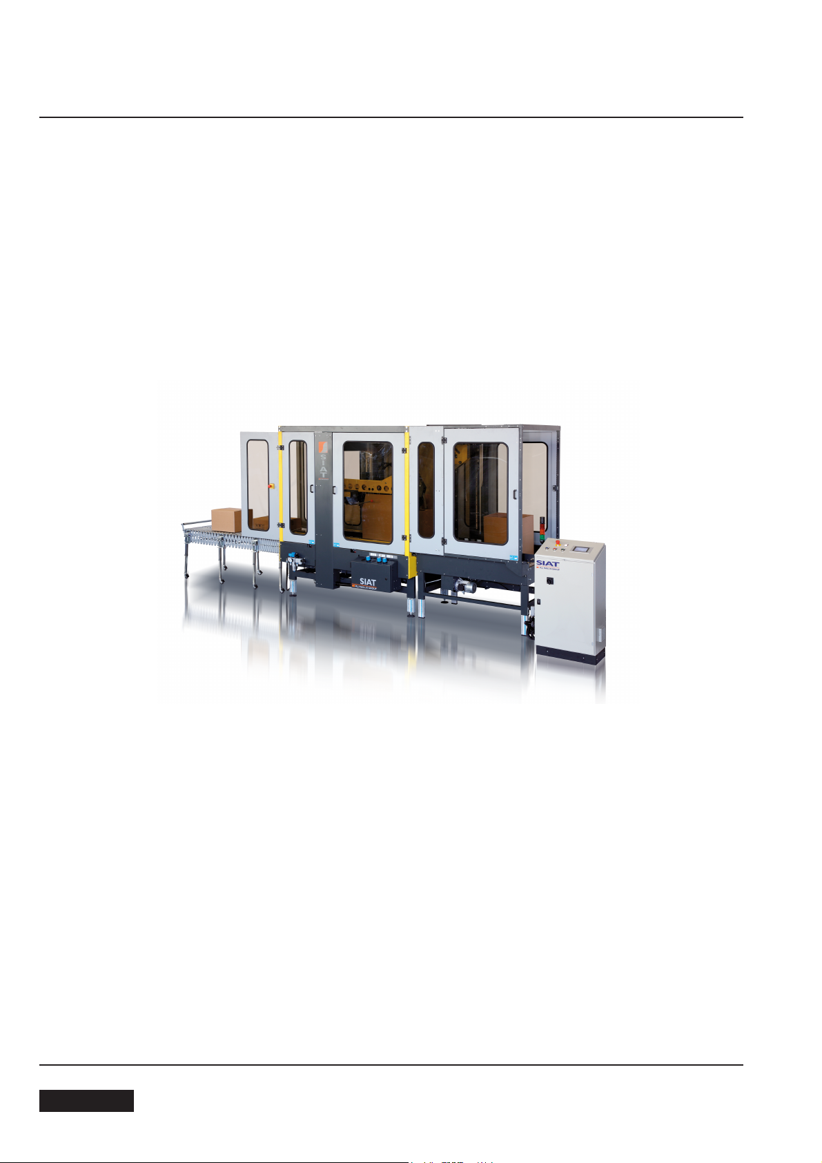
SM446 HS
AUTOMATIC CASE SEALING MACHINE WITH DRIVE SIDE BELTS
- Maximum box size: h. 650 mm x w. 650 mm x l 800 mm
- Minimum box size: h. 150 mm x w. 160 mm x l 300 mm
- Adhesive tape: w. 50/70 mm
- Belt speed: 30 m/min.
- Production: 11 boxes/minute
- Average air consumption: 260 Nl/min approximately
ENGLISH
April 20132

INDEX
ABBREVIATIONS AND ACRONYMS
Section
Manufacturing specifications 1.1
Manual, how to use the 1.2
3ytefaS
1.2rebmuN laireS
After-sale service 2.2
3.2ytnarraW
Operators' skill levels 3.6
Technical specifications 4.2
6.4snoisnemiD
5noitatropsnarT
6gnikcapnU
7noitallatsnI
8slortnoC
9noitarepO
01secived ytefaS
Set-up and adjustments 11
21esu enihcaM
Tape replacement 12.3
Trouble shooting 12.7
31ecnanetniaM
Blade replacement 13.9
LIST OF ABBREVIATIONS, ACRONYMS AND UNUSUAL
TERMS TO BE FOUND IN THIS MANUAL
Dwg. = drawing
Encl. = enclosure
Ex. = example
Fig. = figure showing spare parts
Max. = maximum
Min. = minimum
Mod. = machine model
N. = number
N/A = not applicable
OFF = machine stopped
ON = machine running
OPP =
Pict. = picture
PLC = Programmable Logic Control
PP = polypropylene
PTFE = Polytetrafluorethylene
4.21gninaelC
5.31noitacirbuL
PVC = Polyvinylchloride
Ref. = reference mark
SIAT SPA = Società Internazionale Applicazioni
Tav. = Illustration
oriented polypropylene adhesive tape
Tecniche (Società per Azioni)
Belt replacement 13.10
Adjustment of belt tension 13.11
Additional Instructions 14
51serusolcnE
April 2013
w = width
h = height
noitces tsalstrap erapS
l = length
ol = overall length
cbh = conveyor bed height
3
ENGLISH
1-INTRODUCTION
1.1 MANUFACTURING SPECIFICATIONS
The automatic case sealing machine Mod. SM44 HS has been designed and manufactured compling with the
legal requirements in force at the date of its manufacture.
THE REFERENCE DOCUMENTS ARE:
Machines guidelines 2006/42/CE
Standards applied
NI EN 415-7
U
N 415-9:2009
E
Guidelines E
Standards applied
EI EN 60204-1:2006
C
N 61000-6-2:2005
E
E
N 61000-6-4:2007
1.2 HOW TO READ AND USE THE INSTRUCTION MANUAL
1.2.1 IMPORTANCE OF THE MANUAL
The manual is an important part of the machine; all information contained herein is intended to enable the equipment to be maintained in perfect condition and operated safely. Ensure that the manual is available to all operators of this equipment and is kept up to date with all subsequent amendments. Should the equipment be sold
or disposed of, please ensure that the manual is passed on. Electrical and pneumatic diagrams are included in
the manual. Equipment using PLC controls and/or electronic components will include relevant schematics or programmes in the enclosure, and in addition the relevant documentation will be delivered separately.
MC 2004/108/CE
1.2.2 MANUAL MAINTENANCE
Keep the manual in a clean and dry place near the machine. Do not remove, tear or rewrite parts of the manual
for any reason.
Use the manual without damaging it.
In case the manual has been lost or damaged, ask your after sale service for a new copy, quoting the code number of the document.
1.2.3 CONSULTING THE MANUAL
The manual is composed of:
- pages which identify the document and the machine
- index of the subjects:
- instructions and notes on the machine: sections 2÷14
- enclosures, drawings and diagrams:
sections 15÷16
- spare parts: last section.
All pages and diagrams are numbered. The spare parts lists are identified by the figure identification number.
All the notes on safety measures or possible dangers are identified by the symbol:
All the important warning notes related to the operation of the machine are identified by the symbol:
The parts typed in bold refer to technical data or technical notes on a specific subject.
1.2.4 HOW TO UPDATE THE MANUAL IN CASE OF MODIFICATIONS TO THE MACHINE
Modifications to the machine are subject to manufacturer’s internal procedures.
The user receives a complete and up-to-date copy of the manual together with the machine.
Afterwards the user may receive pages or parts of the manual which contain amendments or improvements
made after its first publication.
The user must use them update this manual.
;
ENGLISH
April 20134
2-GENERAL INFORMATION
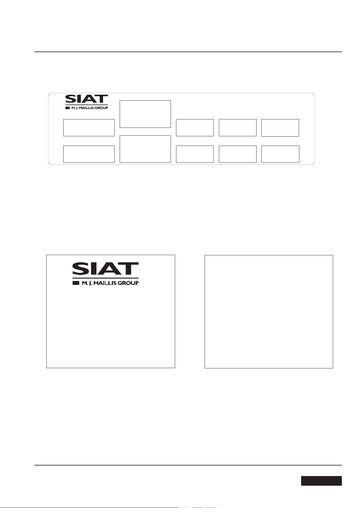
2.1 SERIAL NUMBER OF THE MACHINE AND NAME OF THE MANUFACTURER
Model
Type
Part Number
Year
Serial Number
Volt
SIATs.p.a.Via G.Puecher N°22
Turate (CO) ITALY
Ampere
Hertz
2.2 FOR AFTER-SALE SERVICE AND SPARE PARTS PLEASE APPLY TO:
Watt
Phase
Via Puecher, 22
22078 TURATE (CO) - ITALY
Tel. 02-964951
Fax. 02-9682239
E-mail siat@siat.com
AGENT/DISTRIBUTOR OR LOCAL
AFTER SALE SERVICE:
April 2013
5
ENGLISH

2-GENERAL INFORMATION
WARRANTY
Within the limits of what is set forth below, Seller agrees to repair or replace without cost to Buyer any defective goods when such defect occurs within a period of twelve (12) months from the date in which Seller's goods have been put into use, but in no event beyond
thirteen (13) months from the date of shipment.
Expressly excluded from this warranty are those parts subject to normal wear and tear (by way of illustration, but not limitation, such
parts as belts, rubber rollers, gaskets, brushes, etc.) and electrical pa
Buyer must immediately notify Seller of any defect, specifying the serial number of the machine.
Buyer shall send to Seller the defective item for repair or replacement. Seller will perform the repairs or provide a replacement within a
reasonable period of time.
Upon effecting such repair or replacement, Seller shall have fulfilled its warranty obligations. In the event the repairs or replacement
must be effected at the place where the machine is installed, all expenses for labor, travel and lodging of Seller's personnel shall be
sustained by the Buyer. Buyer wil
Seller is not responsible for defects resulting from:
- Improper use of the machine
- Lack of proper maintenance
- Tampering with the machine or repairs effected by the Buyer.
l be invoiced in conformity with Seller's standard charges for the services rendered.
rts.
Seller will not be liable for any injury to persons or things or for the failure of production. With respect to the materials not manufactured by Seller, such as motors and electrical equipment, Seller will grant to Buyer the same warranty Seller receives from its supplier of
such materials. Seller doe
be installed, nor does it warrant compliance with laws or standards relating to the prevention of accidents or pollution.
Adaptation of Seller's machines to the aforesaid laws or standards shall be the responsibility of Buyer who assumes all liability therefore.
Buyer shall indemnify and hold Seller harmless against any claim by third parties resulting from failure to comply with the aforesaid laws
and standards.
s not warrant the compliance of its machines with the laws of non-EEC countries in which the machines may
ENGLISH
6
April 2013

3-SAFETY
3.1 GENERAL SAFETY INFORMATION
Read all the instructions carefully before starting the work with the machine; please pay particular attention to
sections marked by the symbol
The machine is provided with a complete safety protection
and with a two LOCKABLE EMERGENCY STOP BUTTON
placed on the same protection and on the control panel;
when one button is pressed, it stops the machine at any point
in the working cycle.
Disconnect the machine from the mains before any maintenance operation.
.
Keep this manual in a handy place near the machine: its information will help you to maintain the machine in
good and safe working condition.
3.2 DEFINITION OF THE OPERATORS' QUALIFICATIONS
- Machine operator
- Maintenance technician
- Electrician
- Manufacturer’s technician
Only persons who have the skills described in the following page should be allowed to work on the machine.
It is the responsibility of the user to appoint the operators having the appropriate skill level and the appropriate
training for each category of job.
SKILL 1
MACHINE OPERATOR
This operator is trained to use the machine with the machine controls, to feed cases into the machine, make
adjustments for different case sizes, to change the tape and to start, stop and restart production.
N.B.: the factory manager must ensure that the operator has been properly trained on all the machine functions
before starting work.
April 2013
7
ENGLISH

3-SAFETY
SKILL 2
MECHANICAL MAINTENANCE TECHNICIAN
This operator is trained to use the machine as the MACHINE OPERATOR and in addition is able to work with
the safety protection disconnected, to check and adjust mechanical parts, to carry out maintenance operations
and repair the machine.
He is not allowed to work on live electrical components.
SKILL 2a
ELECTRICAL MAINTENANCE TECHNICIAN
This operator is trained to use the machine as the MACHINE OPERATOR and in addition is able to work with
the safety protection disconnected, to make adjustments, to carry out maintenance operations and repair the
electrical components of the machine.
He is allowed to work on live electrical panels, connector blocks, control equipment etc.
SKILL 3
SPECIALIST FROM THE MANUFACTURER
Skilled operator sent by the manufacturer or its agent to perform complex repairs or modifications, when agreed
with the customer.
3.3 INSTRUCTIONS FOR A SAFE USE OF THE MACHINE
Only persons who have the skills described on the following paragraph 3.6 are allowed to work on the machine.
It is responsibility of the user to appoint the operators having the appropriate skill level and the appropriate
training for each category of job.
3.4 STATE OF THE MACHINE
List of the modes which are possible with this machine:
- automatic running;
- running with safety protections removed or disabled;
- stopped by using the main switch;
- stopped by using the lockable emergency stop button;
- electric power disconnected;
- compressed air disconnected.
ENGLISH
April 20138

3-SAFETY
3.5 NUMBER OF THE OPERATORS
The operations described hereinafter have been analized by the manufacturer; the number of operators
shown for each operation is suitable to perform it in the best way.
A smaller or larger number of operators could be unsafe.
3.6 OPERATORS’ SKILL LEVELS
The table below shows the minimum operator's skill for each operation with the machine.
OPERATION
Installation and set up of the machine
Tape replacement
Replacement of blades
Replacement of drive belts
Ordinary maintenance
MACHINE MODE
Running with safety protections disabled.
Stopped by pressing the EMERGENCY
STOP button.
Electric power disconnected.
Electric power disconnected.
Electric power disconnected.
OPERATOR’S
SKILL
2 e 2a
1
2
2
2
NUMBER OF
OPERATORS
2
1
1
1
1
Extraordinary maintenance (mechanical)
Extraordinary maintenance (electrical)
Extraordinary maintenance (pneumatic)
April 2013
Running with safety protections disabled.
Running with safety protections disabled.
Stopped by pressing the EMERGENCY
STOP button.
9
3
2a
3
1
1
1
ENGLISH
3-SAFETY
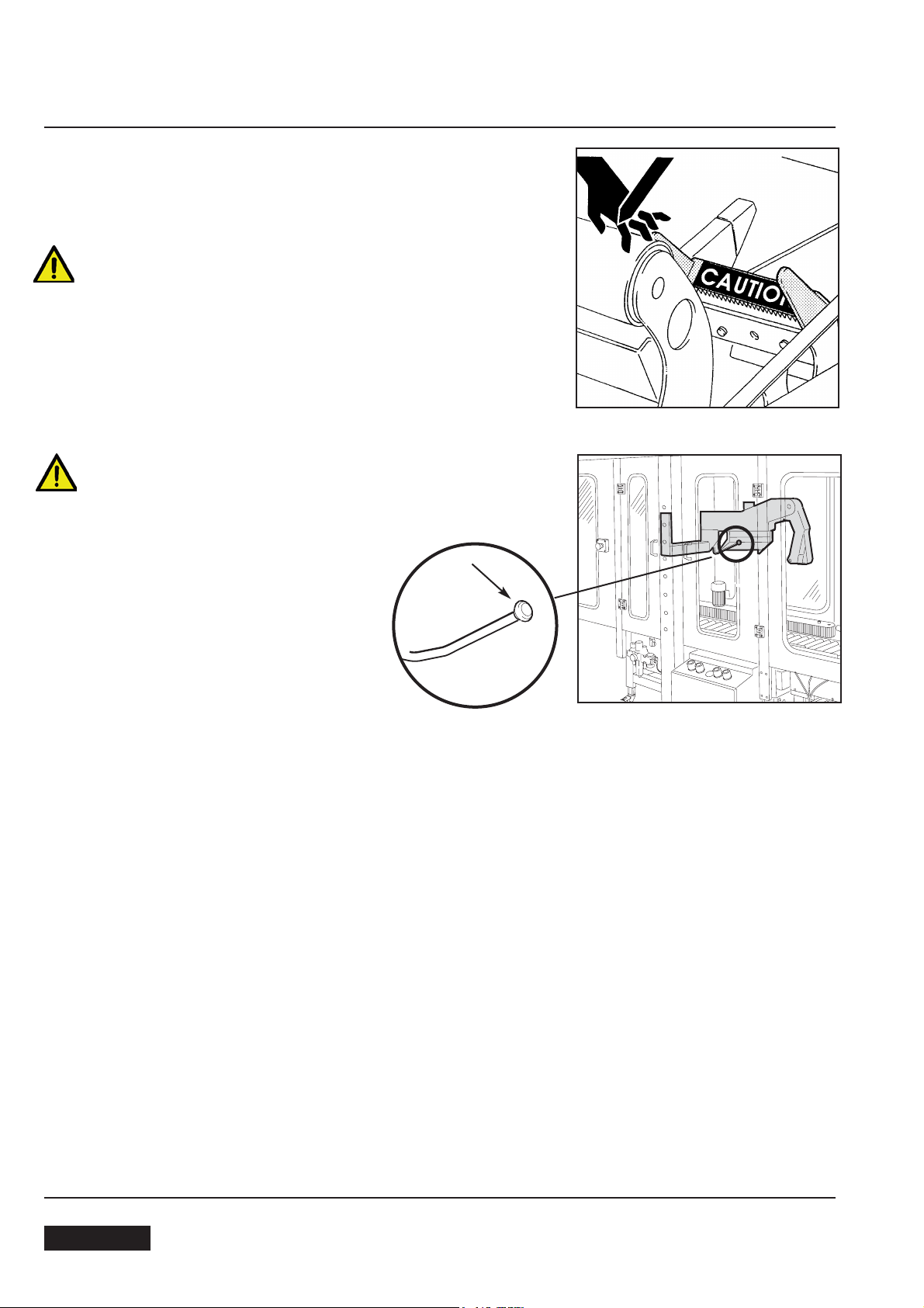
3.7 RESIDUAL HAZARDS
The case sealer SM44 HS has been designed following the EC directives, and incorporates various safety protections which should never
be removed or disabled.
Notwithstanding the safety precautions conceived by the designers of
the machine, it is essential that the operator and service personnel be
warned that the following uneliminable residual hazards exis
WARNING! Tape cutting blades.
Never remove the safety device which covers the blade on the top and
bottom taping units.
Blades are extremely sharp. Any error may cause serious injuries.:
WARNING!: Side flaps fold device guard knobs
Don’t remove the orange plastic guard knobs on the side flaps fold device ends.
3.8 RECOMMENDATIONS AND MEASURES TO PREVENT OTHER HAZARDS WHICH CANNOT BE ELIMINATED
The operator must stay on the working position shown on paragraph 12.1. He must never touch the running
driving belts or put his hands inside any cavity.
The box must be fed by keeping the hands in the right position.
The operator must pay attention to the blades during the tape replacement.
3.9 PERSONAL SAFETY MEASURES
(Safety glasses, safety gloves, safety helmet, safety shoes, air filters, ear muffs).
None is required, except when recommended by the user.
ENGLISH
April 201310
3-SAFETY
3.10 PREDICTABLE ACTIONS THAT ARE INCORRECT AND NOT ALLOWED
- Never try to stop or hold the box while it is being driven by the belts.
Use only the EMERGENCY STOP BUTTON.
- Never work without the safety protections.
Never remove or disable the safety devices.
-
- Only authorised personnel should be allowed to carry out the adjustments, repairs or maintenance which require operation with reduced safety protections. During such operations, access to the machine must be restricted. When the work is finished, the safety protections must immediately be reactivated.
- The cleaning and maintenance operations must be performed after disconnecting the electric power.
- Clean the machine using only dry cloths or light detergents. Do not use solvents, petrochemicals etc.
- Do not modify the machine or any part of it. The manufacturer will not be responsible for any modifications.
- We advise to apply directly to Siat for modifications.
- Follow carefully the installation instructions of this manual.
The manufacturer will notbe responsible for damages caused by improper installation.
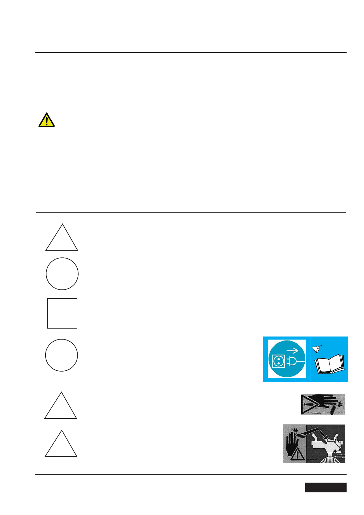
3.11 TABLE OF WARNINGS, LABELS, PLATES AND DRAWINGS TO BE FOUND ON THE MACHINE
SYMBOLS
DANGER AND PARTS IN MOVEMENT
COMPULSORY ACTIONS/PROHIBITION
CONTROLS AND INFORMATION
a
Before starting any maintenance operations the electrical power must be disconnected.
COLOURS
YELLOW COLOUR
RED COLOUR
LIGHT BLUE COLOUR
Label code
: 3.0.01097.96A
b
c
April 2013
Show the sharp knife on the taping head.
Tape threading path for bottom taping unit and position of the sharp knife.
11
Label code: 3.0.01028.96A
Label code: 3.0.01024.96A
ENGLISH
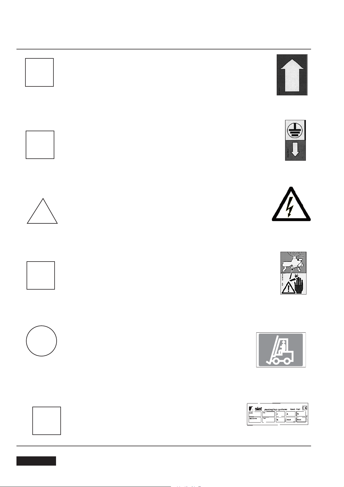
3-SAFETY
d
e
Shows the running direction of the belts.
Label code: 3.0.01040.96A
Show the earth wire connection point on the machine
frame.
Label code: 3.0.01039.96A
f
Caution!: High voltage
Label code: 3.0.01100.96A
g
Tape threading path for upper taping unit.
Label code: 3.0.01023.96A
h
Compulsory position to lift the machine with forktrucks or other suitable raising equipment.
Label code
SBC0010337
: SBC0010337
i
ENGLISH
Identification data for the machine model, serial number and manufacturer.
Label code:S340277700A
April 201312

4 - PRELIMINARY INFORMATION
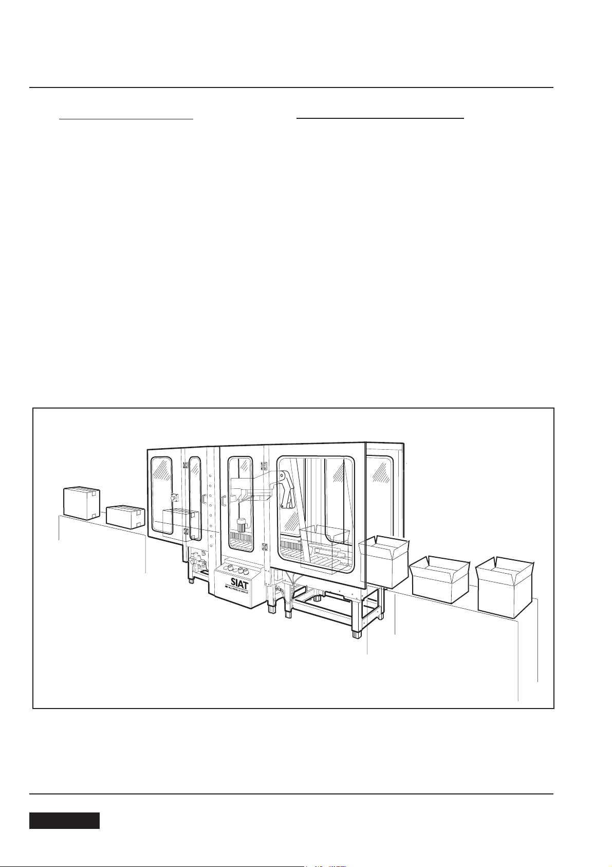
4.1 GENERAL DESCRIPTION OF THE MACHINE
The SM446 HS case sealer with side drive belts is designed to seal boxes by applying two tape strips on the
top and bottom flaps simultaneously. No operator is required.
The machine adjusts itself automatically to the case size and folds the 4 upper flaps. The introduction of the
cases into the machine is performed by the indexing system AS24. All the operations are managed by a PLC
located in the controls board.
4.2 TECHNICAL SPECIFICATIONS
- Production = 660 boxes/hour (average)
- Standard power supply = see plate
- Installed power: 2,388 kW + 0,370 kW (AS26 HS)
- Taping units K11 or K12, tape width 50/75 mm
- Machine+control board+AS24 weight=480+70+90 kg
- Compressed air = 6 BAR; feeding pipe diameter 10 mm
- Belts speed = 30 m/min.
- Infeed conveyor speed: 21 m/min.
- Air consumption: 260 Nl/min
A
C
B
TAPE DIMENSIONS
Suitable adhesive tapes:
PVC
OPP
ADHESIVE PAPER
4.3 PURPOSE OF THE MACHINE
The purpose of this machine is the sealing with adhesive tape of boxes having the dimensions (in millimeters)
shown in the table below:
h
BOXES DIMENSIONS
SM44 HS
min. 160 150 300
w h l
A = 410 mm max
B = 50/75 mm
C = 76 mm
l
w
max. 650 650 800
CASE WEIGHTS
min.: 2 kg
max.: 30 kg
Warning: The machine supplied with the standard electric system is not designed for use in atmosphere with risk of
deflagration. In such conditions the machine must be equipped with anti-deflagration components and/or air motors.
April 2013
13
ENGLISH
4-PRELIMINARY INFORMATION
4.4 MAIN COMPONENTS
The machine is composed of:
n. 1 frame
n. 4 adjustable legs
n. 2 columns
n. 2 taping units
n. 1 top head
n. 2 side drive belts
n. 2 electric motors
n. 1 safety guard
n. 2 emergency stop button
n. 1 controls board
For the technical features of the electric parts refer to section 15-ENCLOSURES
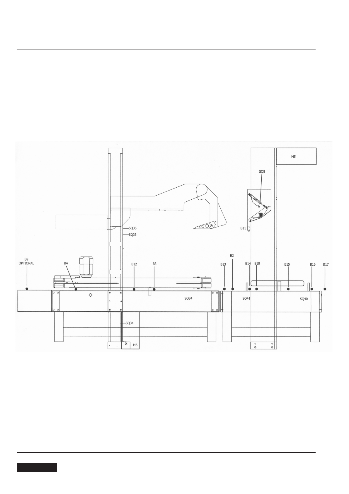
4.5 OPERATIVE FLOW
The boxes, coming from the filling stations, are centred, gated and fed to the machine by the indexing unit
AS26 HS.
The same indexing unit is equipped with a reading head for the identification of the format of the introduced box
and the position of the following upper forming group correctly by appropriate electro-pneumatic interface devices.
The driving belts transport the box during the different phases, from flaps folding to the following sealing, to the
exit of the same box.
The infeed conveyor is composed of:
n. 1 frame
n. 4 adjustable legs
n. 1 electric motor
n. 1 motorized belt
4.6 MACHINE NOISE MEASUREMENT
Acoustic pressure at 1 meter distance from the machine with the tape roll inserted: 73 dB. Acoustic pressure
at a height of 1,6 meter above the
The measurement has been performed by a SPYRI-MICROPHON phonometer..
machine
with the tape roll inserted: 73 dB.
ENGLISH
April 201314
4-PRELIMINARY INFORMATION
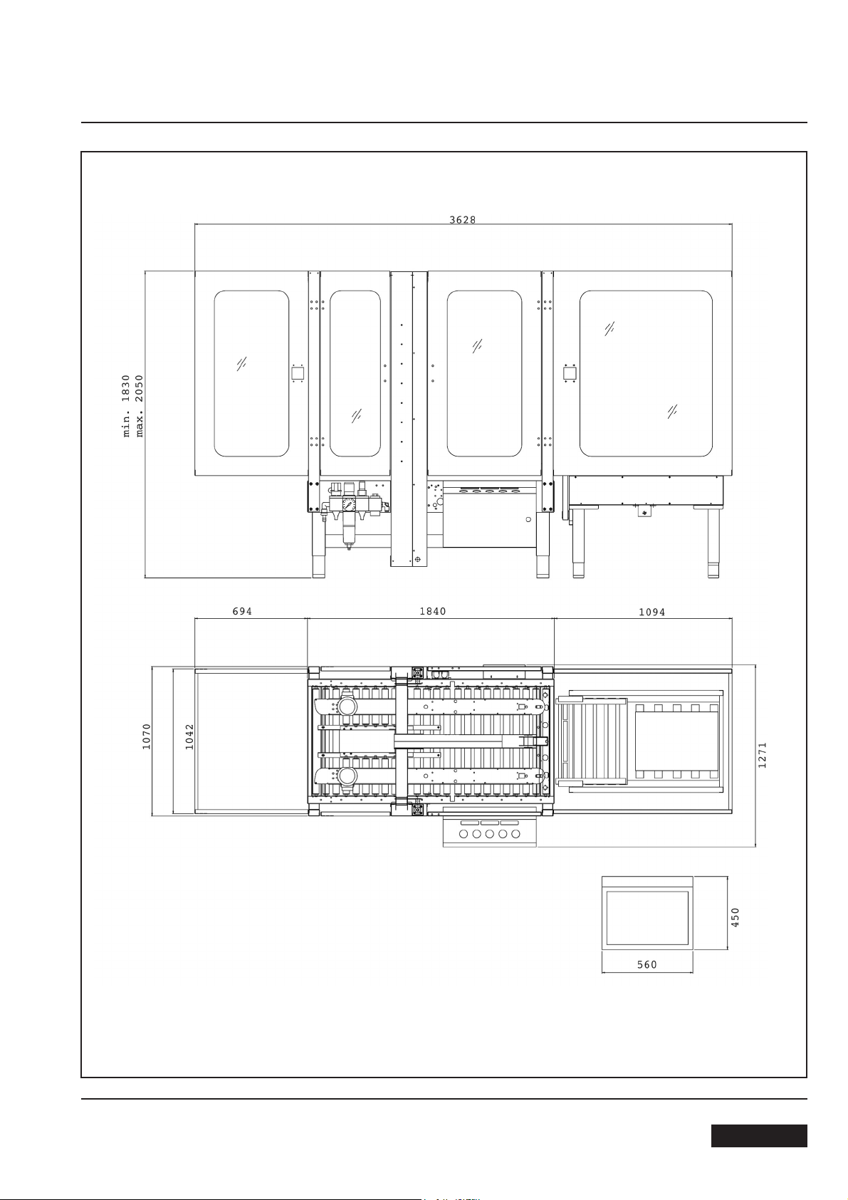
4.7 OVERALL DIMENSIONS
April 2013
15
ENGLISH
5-SHIPMENT - HANDLING - STORAGE
5.1
MACHINE TRANSPORTATION AND HANDLING
The machine and the infeed conveyor are shipped in 2 separate packings, fixed on a wooden pallet. They can be lifted with a normal fork
lift. The standard packing is suitable for surface and air transportation.
Oversea packing on request.
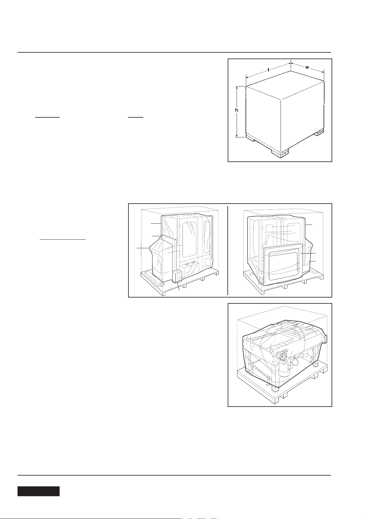
Packing dimensions
SM44HS
l= length: 2600 mm l: length: 2600 mm
w= width: 2250 mm w= width: 2250 mm
h= height: 1500 mm h= height: 1500 mm
Weight: 850 kg Weight: 350 kg
5.2 PACKING FOR OVERSEAS SHIPMENT
(OPTIONAL)
The machines shipped by sea freight are covered by an aluminium/polyester (Vacupol) bag which contains dhydrating salts.
AS24
Machine packing
-machine 1
-control board 2
-guards 3
-accessories 4.
Indexing unit packaging.
1
3
2
4
1
3
2
5.3 STORAGE OF THE PACKED OR UNPACKED MACHINE
In case the machine must stay inactive for a long period, please take the following precautions:
- store the machine in a dry and clean place;
- if the machine is unpacked it is necessary to protect it from the dust;
- do not stack anything on top of the machine;
ENGLISH
April 201316
6-UNPACKING
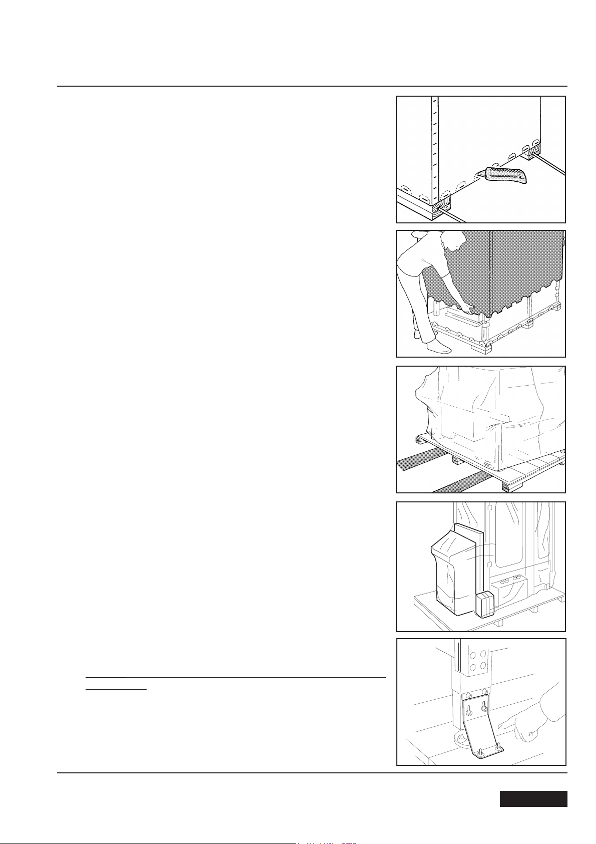
6.1 Cut the polypropylene straps.
Use a cutter to remove the part of the carton fixed by the staples
along the entire perimeter of the packing. (Otherwise remove the
staples by using a suitable tool)
After having cut the carton or removed the staples, lift the packing up
in order to free the machine. (2 persons)
Move the machine and the infeed conveyor to where they will be located.
Cut the stretch film and remove the control board, the guard panels
and the accessories box.
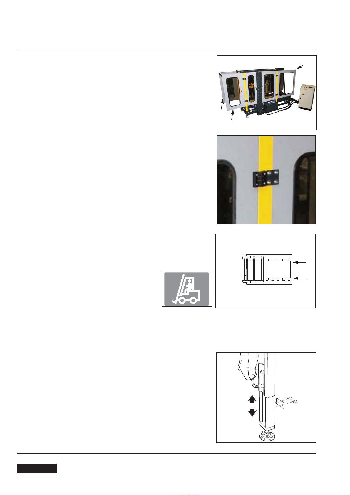
Sealing machine brackets removal
Caution:
one at a time.
the operations must be accomplished on all the four legs
Remove the screws 1;
Unscrew the nut 2 and remove the bracket;.
Replace and tighten the screws 1;
Acting in similar way on the other legs, in sequence.
April 2013
17
ENGLISH
6-UNPACKING
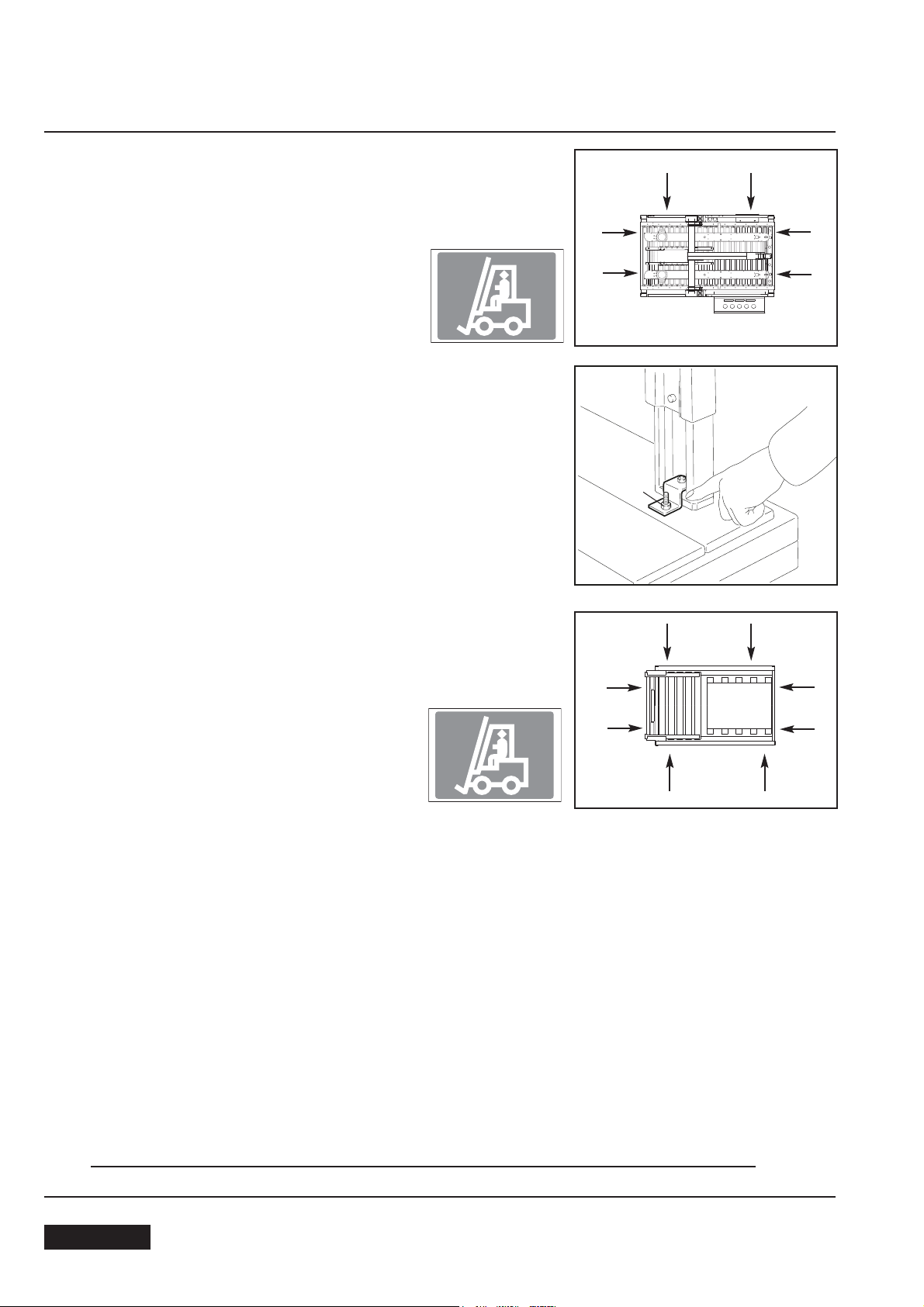
To lift the machine up, position the lift forks where there are the labels
on right hand side or front-back sides and remove the pallet.
Machine weight + control board: 480 + 100 kg.
Conveyor brackets removal
Loosen the nuts 1 and remove the brackets.
SBC0010337
Back sdie
1
RH side
Front sdie
To lift the conveyor, position the lift forks where there are the labels
on front or back side and remove the pallet.
Conveyor weight: 90 kg
6.4 PACKING DISPOSAL
The packing of the machine Mod. SM44 HS
is composed of:
- wooden pallet
- carton box
- wooden supports
- steel fixing brackets
- polythene foam protection
- plastic straps (PP)
- clay dehydrating pouches
- aluminum/polyester/polythene bag
(only for seafreight shipments)
SBC0010337
Back sdie
RH side
Front sdie
LH side
For the disposal of these materials please follow the provisions of the law in your country.
ENGLISH
April 201318
7-INSTALLATION
7.0. SAFETY MEASURES
Read carefully chapter 3.
7.1. ENVIRONMENTAL CONDITIONS REQUIRED
-Temperature min. = 5 °C; max. 40 °C
-Umidity min 30%; max. 80%
-Dust free environment
7.2. SPACE REQUIRED FOR MACHINEOPERATION AND
MAINTENANCE
Min. distance from the wall: A = 1500 mm; B = 1000 mm;
Min. height:= 2500 mm
7.3 SPARE PARTS AND THREADING TOOL FOR TAPING HEADS
For a detailed description of the tools kit see section 13.1.
B
A
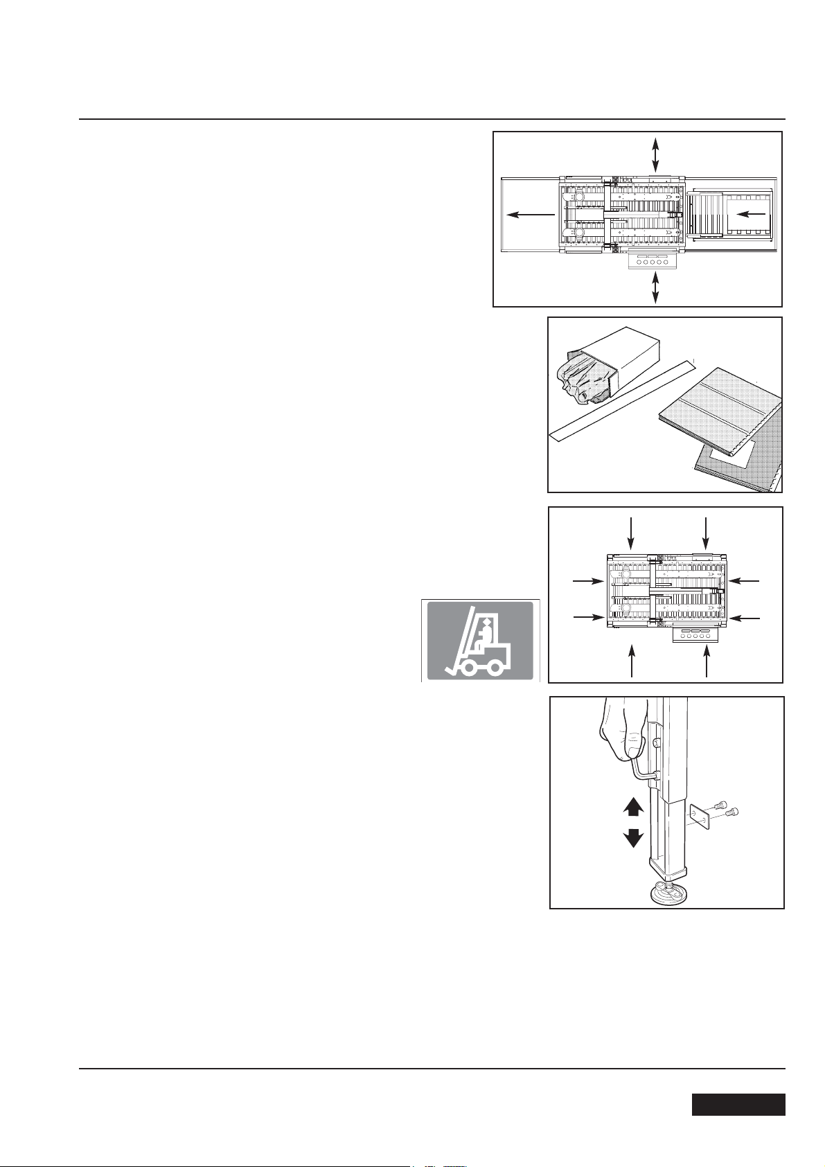
7.4 MACHINE POSITIONING
Raise the machine with a fork lift positioning the lift forks under the
points where there are the labels.
7.4.1 WORK HEIGHT ADJUSTMENT
Lift the machine as shown in picture.
Unlock the screws and take the legs out looking for the desired con-
veyor bed height on the graduated label.
Then lock the screws again.
SBC0010337
April 2013
19
ENGLISH
7-INSTALLATION
7.5 SAFETY GUARDS: INSIDE AND OUTSIDE MACHINE
EMERGENCY STOP PUSH-BUTTON
Position and assemble the inside (A) and outside (B) guard panels
with the upper and bottom brackets and stiffening frofile plates as
shown in the pictures.
7.5.1. INSIDE SAFETY GUARDS
Support brackets (upper and bottom); 2+2 socket head screws each
bracket.
A
B
B
7.6 CONNECTION BETWEEN THE INDEXING UNIT AS24 AND THE
MACHINE SM44 HS
Lift the indexing unit by placing the forks under the points where the
labels are.
7.6.1 Move the indexing unit to the machine and fix it using the screws previously removed.
7.6.2 Unlock the screws of the legs, move the legs down to the floor and
lock the screws.
SBC0010337
ENGLISH
April 201320
7-INSTALLATION
7.7 EMERGENCY STOP BUTTON
Furthermore mount the complete bracket with emergency stop button.
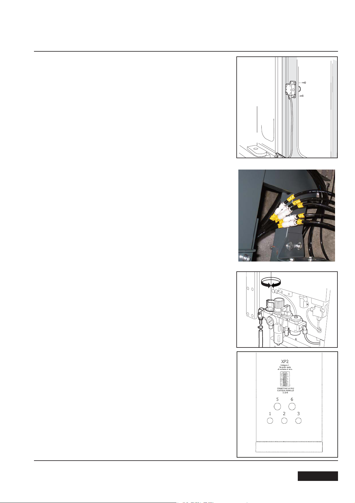
7.8 PNEUMATIC CONNECTION
Connect air pipes from the sealing machine to the conveyor centring
guides cylinder connectors and to infeed conveyor cylinders.
Fitting acronyms shown in the picture identify the pipes number
coming from the machine.
5A – 5B – 7B – 11A – 11B
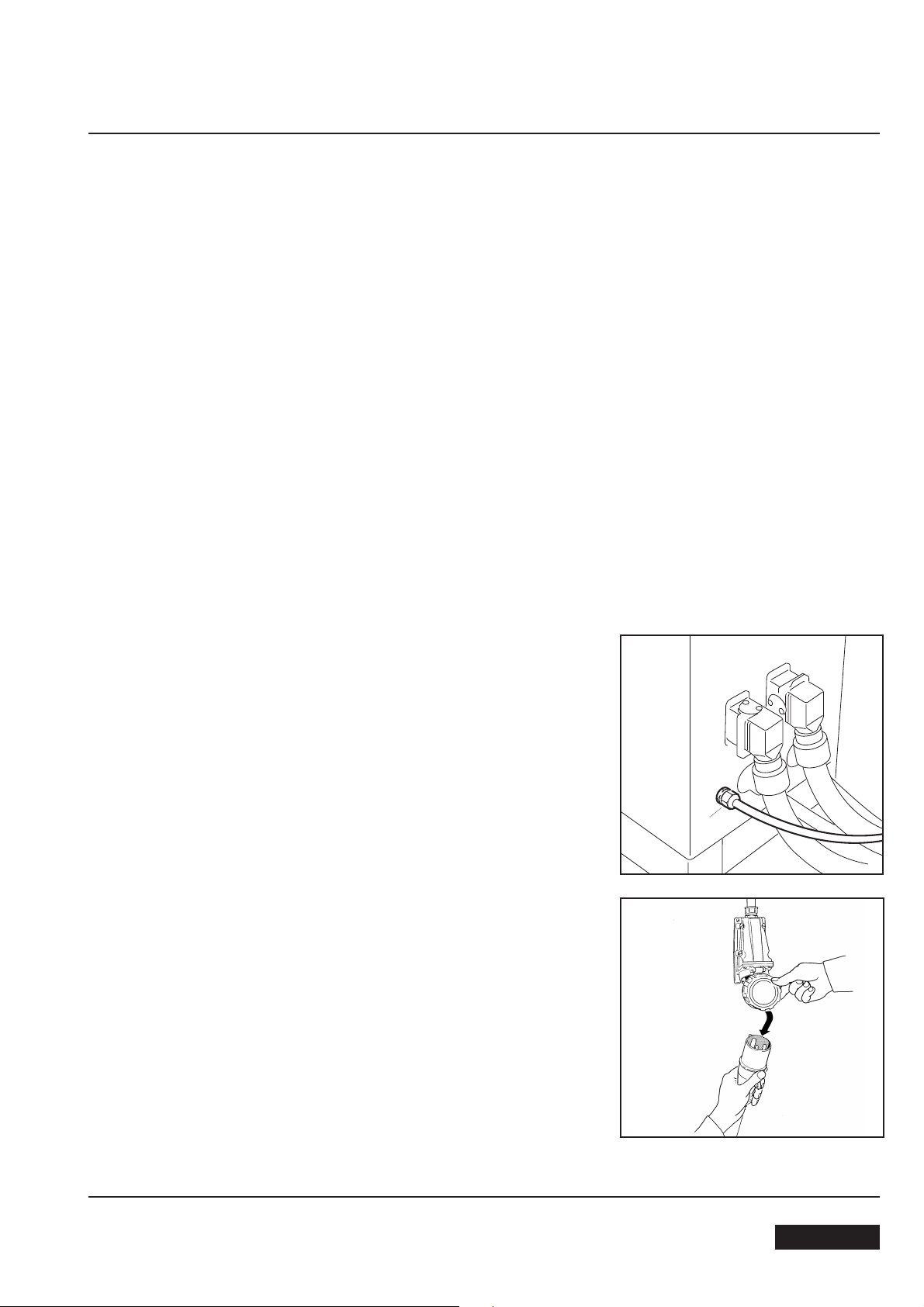
7.9 MAIN PNEUMATIC CONNECTION
Connect an air pipe to the ON-OFF valve and fix it with a strap.
Min. inside diameter of the pipe 10mm.
Air pressure 6÷7 BAR
Give air to the machine by the ON-OFF valve.
7.10 CONTROL BOARD CONNECTION
Place the control board near the machine.
Feeding cables:
Connect the two cables with multipolar connectors from the machine
and from the indexing unit to the control board.
1. Feeding cable (net)
2. Carton sealer front box (CA1)
3. Carton sealer rear box
5. Indexing unit box and vertical electrical axis motors.
6. Carton sealer front boxes (CA2)
April 2013
21
ENGLISH
7-INSTALLATION
7.11 Carton sealer front box
Box CA1
Cables n.3 and 6
CA2
Cable n. 6
Cable n. 3
CA1
Carton sealer front box
Box CA2
Cable n. 6
Connectors:
W77 Motor
W78
ENGLISH
April 201322

7-INSTALLATION
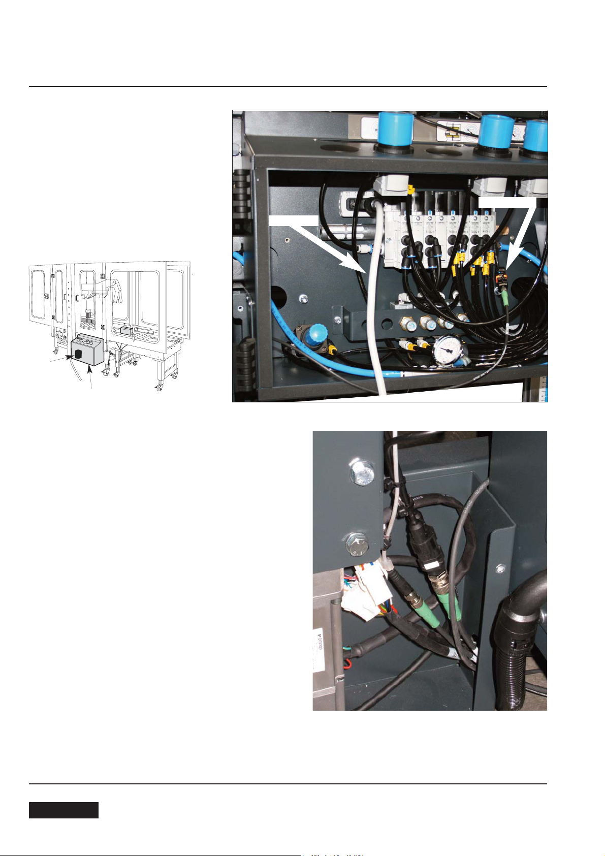
7.12 Carton sealer rear box
Cable n. 5
Indexing unit box and vertical axes motors
Cable n.4
Connectors:
W15
XP17
W76-76 motor + ground wire on the fixing screw
April 2013
23
ENGLISH
7-INSTALLATION
Infeed conveyor photocell connection
ENGLISH
April 201324
7-INSTALLATION
7.13 PRELIMINARY ELECTRIC CHECK-OUT
Before connecting the machine to the mains please carry out the following operations:
7.13.1Make sure that the socket is provided with a ground protection circuit and that both the mains voltage and frequency meet the indications on the name plate of the machine.
7.13.2Check that the connection of the machine to the mains meets the provisions of law and/or the safety regulations
in your country.
7.14 MACHINE CONNECTION TO THE MAINS AND CHECK-OUT
Installed power = 2,388 kW
-Connect the power cable (A) of the control board to an electric
socket.
-Standard power supply 400Volt 50 Hz 3Ph + neutral + ground.
A
April 2013
25
ENGLISH
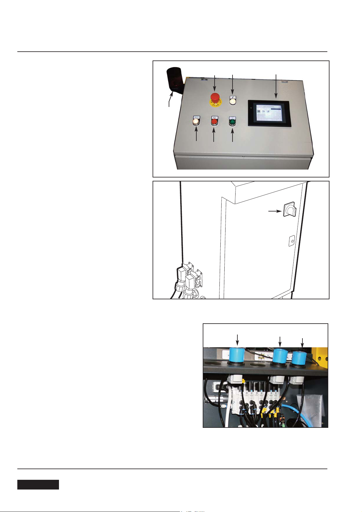
8-CONTROLS
8.1 CONTROL BOARD
1. Main switch
2. Voltage warning light
3. Auxiliaries push button
(control board electrical components enabling)
4. Stop button
5. Start button
6. Touch screen control panel
7. Warning (flashing light + buzzer)
8. Emergency stop button
8
7
3
4
2
5
6
1
8.2 REAR BOX
1 Centering guide pressure regulator
2. Side belts (motorizations) pressure regulator
3. Box height pick-up pressure regulator
WARNING!
In the box there’s a pressure regulator of the compensation
cylinder on the machine vertical axis (dancer).
The regulator is adjusted by the manufacturer during machine assembly and testing (2,5 BAR); the settled value
should never be changed.
ENGLISH
3
2
1
April 201326
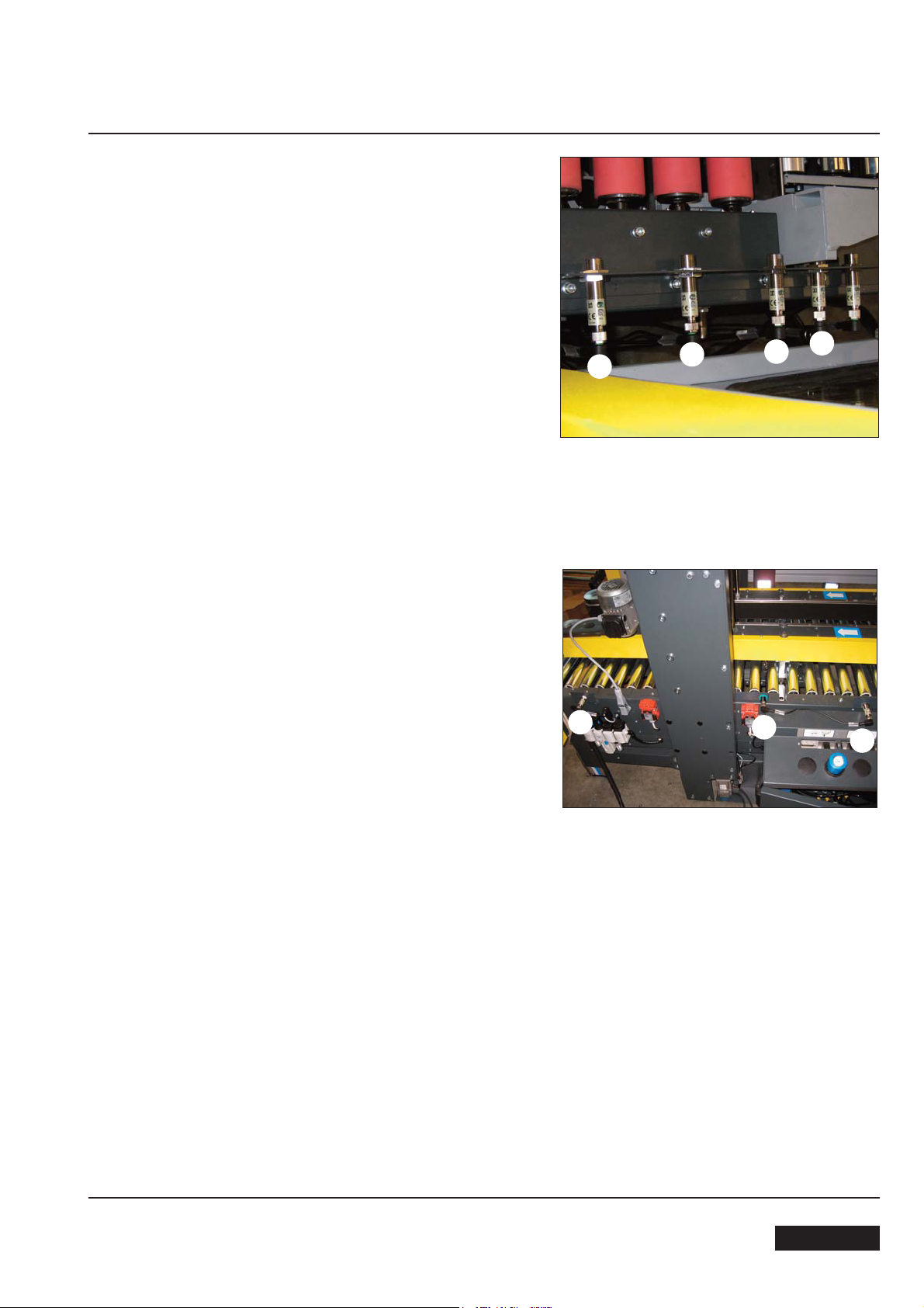
9-OPERATION
9.1 Turn on the air to the machine by the ON/OFF valve; set the
main switch in ON position; close the safety guards; release
the EMERGENCY STOP button; press Auxiliaries button and
Start Button (if there are no alarm signalling).
9.2 Start button activation: motors start (machine and indexing
unit) and lifting of the indexing unit drive belt.
Obscuring photocell n. 1: lowering of indexing unit drive belt
and stop of the corresponding motorization.
Obscuring photocell n. 2: Descent of the reading head and
contemporary closing of the indexing unit levers that line the
box up as necessary; in this phase the “box measurement”
is executed.
Once the measurement is finished the forming-sealing group
is positioned at the corresponding height of the reading + 20
mm, on a floating position, to allow a proper box closing in
any condition.
After the forming-sealing group positioning a lifting of the indexing unit plan follows and the re-start of the corresponding
motorization; the machine works on the box.
Obscuring photocell n. 2: activation of electronic control logic
(cycle start – machine occupied).
Free photocell n. 1: lowering of indexing unit drive belt: with
new photocell obscuring the following box will cause the stop
of the corresponding motorization.
Obscuring photocell n. 3: rear flap folder check.
Obscuring photocell n. 4: motorizations closing.
Free photocell n. 3: start of closing operation of the box rear
flap by the corresponding arm with flap folder device; furthermore, during the
box closing operation.
Obscuring photocell n. 5: rear flap folder check.
transport, the side flap folders compete the
1
4
7
3
2
6
5
Note: during the transit in “area 2” (between photocells n. 4
and n. 5), if the standing box on the indexing unit has got the
same dimensions of the previous one, it’s introduced into the
machine immediately.
Free photocell n. 7: cycle conclusion.
April 2013
27
ENGLISH
9-OPERATION
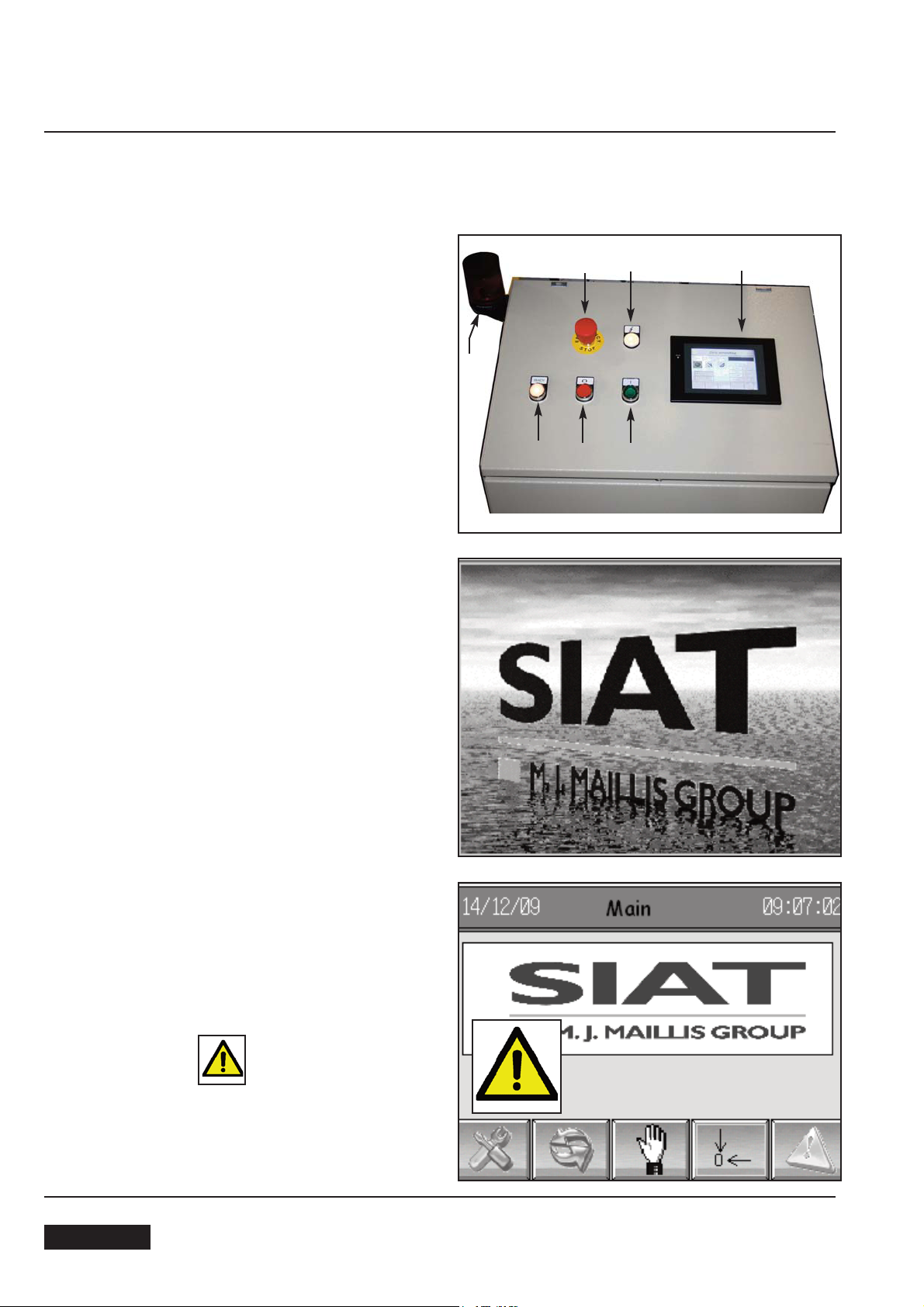
9.3. OPERATION MODES DESCRIPTION
The carton sealer works only in automatic: closed safety protection, free emergency stop button, enabled
control panel and start button activated, open compressed air circuit.
MACHINE START:
- Press auxiliaries button (3); verify the lighting of
the incorporated pilot lamp.
- Wait for the lighting of the control panel (6); this is
a touch screen panel, so to activate a function or to
move amoungst the pages it’s enough to touch the
screen with a finger on the corresponding text or pictures.
7
8
3
4
2
5
6
- Touch any point on the screen to enter the main
page
- In case of alarm signalling in progress, touch the
corresponding symbol with a finger to enter the
alarms page.
ENGLISH
SM446 -HS
April 201328
9-OPERATION
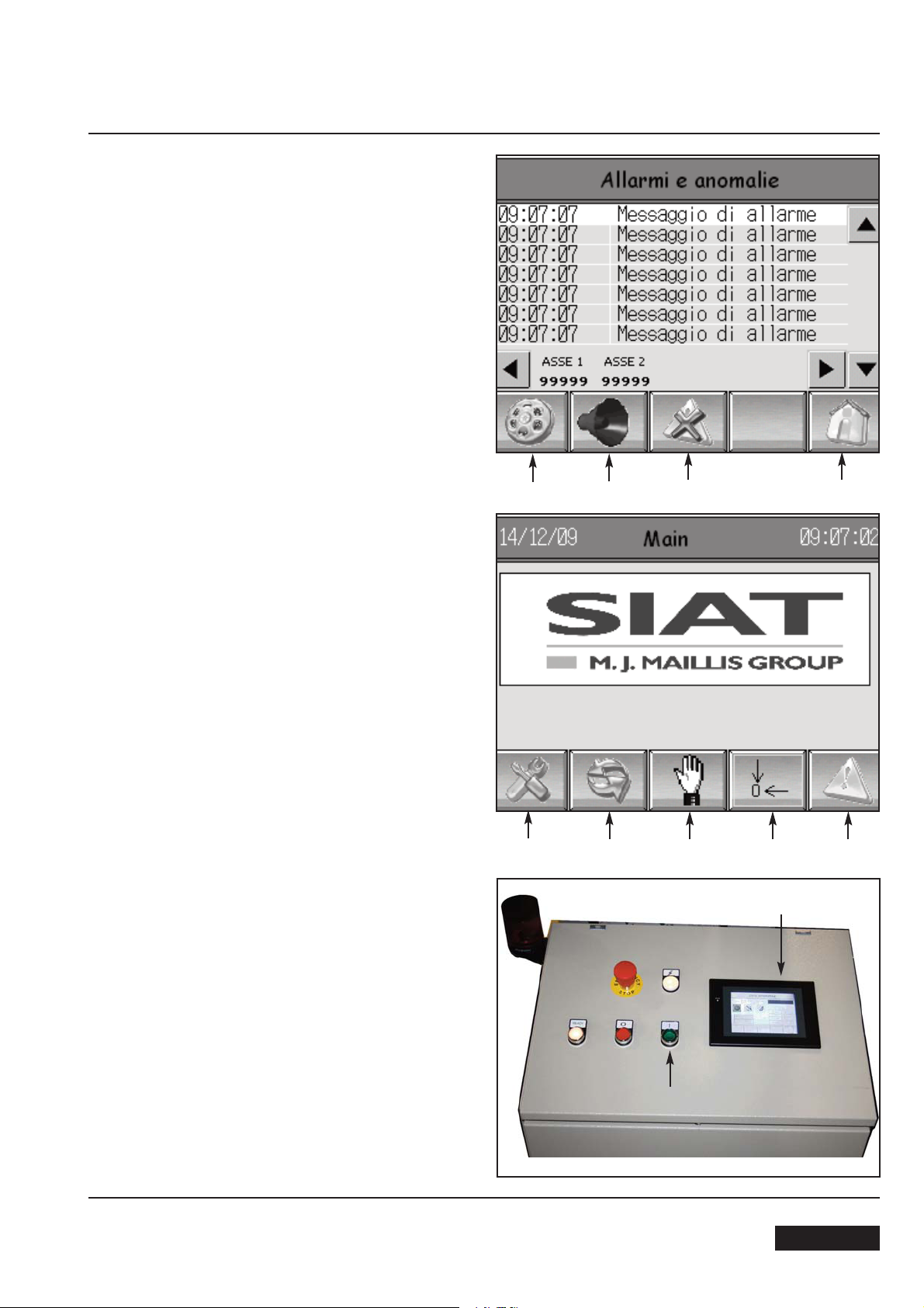
- Reset as necessary after intervention for the elimination
of the problem that caused the alarm signalling.
- Press B
A: Main page
B: Alarm reset
C: Reset acoustic signalling
D: Alarms log
Return to main menu mode (A).
E: Alarms page
F: Machine general reset
G: Page mode of manual machine axes drive
H: Page operation automatic cycle
I: Page of system settings and diagnostics
D
C
B A
SM446-HS
I
H
G
F
6
E
- Press F (reset)
- Press Start button (5), obtaining in this way the rollers
and the indexing unit belt start, the motorizations start
and the visualization of the operation automatic cycle
page (H) on the control board (6).
April 2013
29
5
ENGLISH
ENGLISH
September 201030
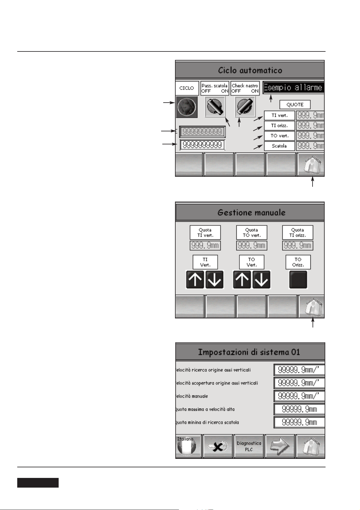
- Mode of page of operation automatic cycle
- In this condition the machine results ready for the starting of the sealing cycle as foreseen.
J- Box counter (total non resettable)
K: Box counter (partial resettable)
L: Indexing unit vertical axe (only visualization)
M: Indexing unit horizontal axe (only visualization)
N: Machine vertical axe (only visualization)
O: Box height (only visualization)
P: Sealing cycle on/off (lighting signalling)
Q: Box upper sealing on/off or “transit” without sealing removing also the top taping unit
R: Alarms signalling tape end/breakage on/off
S: Only visualization: tape end and full line
- Page mode of manual machine axes drive (G)
- Page of system settings and diagnostics (I)
Warning: Values are protected by passwords, in order to
avoid unauthorized changes that could to compromise the
regular machine operation.
Only the machine administrator or authorized personnel
of after sales service can enter the pages of machine management data.
A
J
K
L
M
N
O
P
Q
R
S
A
9-OPERATION
 Loading...