

siat ProWrap 16_L_PW, ProWrap 16_M_FM, ProWrap 16_M_M, ProWrap 16_M_PW, ProWrap 16_H_FM Operation And Maintenance Manual
...
Semi-automatic pallet wrapper
ProWrap
Operation and maintenance
manual
Translation of the “ORIGINAL
INSTRUCTIONS”
Code SBC0035151 ed. 05-2018 - rev. 1

No part of this publication may be reproduced without the written consent of the Manufacturer. Pursuing a policy of continuous improvement, the Manufacturer reserves the right to change this
document without notice, provided that such changes do not create risks to safety.

Summary
Safety information
Purpose of the manual ............................................................................................................ 3
Glossary of the terms .............................................................................................................. 3
Attached documentation ......................................................................................................... 4
General safety warnings ......................................................................................................... 5
Safety Warnings for Handling and Installation ........................................................................ 5
Safety Warnings for Operation and Use.................................................................................. 6
Safety Manager Obligations ................................................................................................ 7
Safety Warnings on Misuse..................................................................................................... 7
Safety Warnings on Residual Risks ........................................................................................ 8
Safety Warnings for Maintenance and Adjustments................................................................ 8
Safety warnings for the electrical equipment .......................................................................... 9
Safety warnings for the environmental impact ...................................................................... 10
Safety and information symbols .............................................................................................11
Technical Specications
general description of the machine ....................................................................................... 13
Description of the main components ..................................................................................... 15
Manufacturer and machine identication .............................................................................. 16
Cycle ..................................................................................................................................... 17
Types of wrapping ................................................................................................................. 18
Residual risks ........................................................................................................................ 19
Incorrect uses that are reasonably expected ........................................................................ 20
Optional Accessories ............................................................................................................. 20
Description of the safety devices .......................................................................................... 21
Technical data of machine ..................................................................................................... 22
Dimensions and weights (Standard version) ..................................................................... 22
Dimensions and weights (version HSD) ............................................................................ 23
Technical specications ..................................................................................................... 23
Technical specications of pressing roller.......................................................................... 23
Specications of the accessories available on request ..................................................... 24
Technical data of reel ............................................................................................................ 24
Dimensions of lm reel ...................................................................................................... 24
Net reel dimensions ........................................................................................................... 24
Description of outer areas ..................................................................................................... 25
Safety and information symbols ............................................................................................ 26
IDM 510-128-1_Sommario
Maintenance
Recommendations for maintenance interventions ................................................................ 27
Scheduled maintenance intervals ......................................................................................... 28
Diagram of the points of lubrication ....................................................................................... 29
Problems, causes, remedies ................................................................................................. 30
Alarm message table ............................................................................................................ 32
Cleaning and replacement of the air lter ............................................................................. 34
Adjustment of chain controlling the rotation of platform ........................................................ 35
Sensitivity adjustment for the product to be wrapped detection photocell ............................ 37
Replacing the rotating platform wheels (standard version) ................................................... 38
Replacing the rotating platform wheels (version HSD) ......................................................... 39
Replacing the lifting belt of the carriage ................................................................................ 41
Pressing roller
Description of the main components of the Pressing Roller ................................................. 44
Disassembly and re-assembly of the Pressing Roller ........................................................... 45
Re-assembly of the Pressing Roller .................................................................................. 46
Reel holding carriage (M)
Reel holding carriage (M) ...................................................................................................... 47
Main components .............................................................................................................. 47
Film Coil Feeding ............................................................................................................... 48
English languageOperation and maintenance manual
1

Tension adjustment of lm ................................................................................................. 49
Cleaning and replacement of brake disc ........................................................................... 50
Replacing the outer surface of roller .................................................................................. 51
Reel holding carriage (FM)
Reel holding carriage (FM) .................................................................................................... 52
Main components .............................................................................................................. 52
Film Coil Feeding ............................................................................................................... 53
Cleaning and replacement of brake disc ........................................................................... 54
Adjustment of brake ........................................................................................................... 55
Replacing the outer surface of roller .................................................................................. 56
Reel holding carriage (PW)
Reel holding carriage (PW) ................................................................................................... 57
Main components .............................................................................................................. 57
Film Coil Feeding ............................................................................................................... 58
Adjustment of drive chain tensioning ................................................................................. 59
Pre-stretch percentage variation (lm pre-stretch kit ) ....................................................... 60
Disassembly and re-assembly of the reel holding carriage ............................................... 62
Control system
Recommendations on Operation and Use ............................................................................ 63
Control description ................................................................................................................ 64
Description of the operator interface ..................................................................................... 65
Operator interface navigation diagram (standard) ................................................................ 66
Operator interface navigation diagram (advanced) ............................................................... 68
Description of a typical screen .............................................................................................. 70
Description of the keyboard .................................................................................................. 70
Function description of the displayed icons .......................................................................... 71
Programming icons (shaded gray background) ................................................................. 71
Display icons (gray background) ....................................................................................... 73
Non-release hold keys (shaded gray background) ............................................................ 74
Single-action keys (orange or shaded gray) ...................................................................... 74
Language selection mode ..................................................................................................... 76
Password entering mode ...................................................................................................... 76
How to programme or edit the parameters ........................................................................... 77
Recipe management ............................................................................................................. 77
How to programme a new recipe ....................................................................................... 77
Modifying a recipe .............................................................................................................. 78
How to load a recipe in the PLC ........................................................................................ 79
How to programme the bands and the wrapping reinforcements ......................................... 80
How to display the wrapping statistics .................................................................................. 84
How to display the Setup parameters ................................................................................... 86
Manual wrapping ................................................................................................................... 88
Normal stop ....................................................................................................................... 89
(Single or double) automatic wrapping .................................................................................. 90
Normal stop ....................................................................................................................... 91
(Single or double) automatic wrapping with sheet feeder ..................................................... 92
Normal stop ....................................................................................................................... 93
Stop in alarm conditions and restart ...................................................................................... 94
Emergency stop and new start-up ........................................................................................ 95
Use of the weighing unit (optional) ........................................................................................ 96
Calculation of lm pre-stretch ................................................................................................ 97
Calculation of lm tensioning ................................................................................................ 98
1Disposal and scrapping
Machine Disposal and Scrapping .......................................................................................... 99
Analytical index ................................................................................................................... 101
2
English language Operation and maintenance manual
IDM 510-128-1_Sommario

Purpose of the manual
– The purpose of the manual is to inform and train operators so that they can inter-
act with the machine in SAFE CONDITIONS.
– Its aim is also to prevent risks, to reduce the social costs resulting from accidents
and damage to the health of people, property and to the environment.
– In some cases, accidents may be due to the Operator using the machine
carelessly.
– Caution is always necessary. Safety is also the responsibility of all the per-
sons interacting with the machine throughout its operating life.
– Remember that it is too late to think about safety issues when the accident
has already occurred.
– It is important to dedicate enough time to read the “Instruction Manual” in
order to minimise the risks and to avoid any unpleasant accidents.
– The content of this manual was originally edited by the Manufacturer in the moth-
er tongue (ITALIAN), in compliance with the professional writing standards and
the regulations in force.
Safety information
– Any translation of the manuals shall be carried out directly and without alterations
from the texts of the ORIGINAL INSTRUCTIONS.
– This applies also to the translations carried out by the agent or by the person who
is in charge of delivering the equipment in the specic linguistic area.
– The Manufacturer reserves the right to update the documentation, should this
prove necessary.
– All information supplied by the recipients represents an important contribution to
the improvement of the after-sales service that the manufacturer will offer to his/
her customers.
– All supplied information is organised into an index and a table of contents, so as
to easily track specic topics of interest.
– The SAFETY WARNINGS and the INSTALLATION MANUAL are supplied as
hard-copy publications.
– The USE AND MAINTENANCE MANUAL, operation diagrams and all other
post-sale documents can be downloaded from the INTERNET.
– Keep the manual and the attached documents in a place known and easily trace-
able, so that you may refer to them whenever necessary.
Glossary of the terms
The glossary includes some terms used when processing information, with
their denition, in order to facilitate understanding.
IDM 510-004-5
– Training: A process aiming at transferring the knowledge, skills and behaviours
required to work in an autonomous, correct and hazard-free manner.
– Assistant: person chosen, trained and coordinated in an appropriate manner to
minimize the risks in carrying out their tasks.
– Emergency stop: voluntary activation of the special control that stops the dan-
gerous elements of the work unit in the case of imminent risk.
– Stop in alarm conditions: this state causes the components to stop and is acti-
vated when the control system detects a problem in the machine operation.
– General shut down: In addition to the normal stop this state also causes the in-
terruption of all the power sources (electrical, pneumatic, etc.).
English languageOperation and maintenance manual
3

– Operating Stop: state that does not cut off power supply to the actuators, but
ensures control system monitoring in safe conditions.
– Size change: a set of interventions to be carried out before beginning to work
with specications different with respect to the ones previously in use.
– Test-run: a series of operations required to ensure compliance to the design
specications, and to commission the machine under safety conditions.
– Installer: a technician chosen and authorized by the manufacturer or his author-
ized representative, among those who full the requirements for installation and
testing of the machine or plant in question.
– Maintenance Operator: a technician chosen and authorized, among those who
full the requirements, to carry out routine and extraordinary maintenance operations on the machine. Therefore, the maintenance operator shall possess precise
knowledge and skills, with particular skills in the relevant eld.
– Routine Maintenance: all the operations necessary to maintain the functionality
and efciency of the machine. Normally, these operations are scheduled by the
manufacturer, who denes the necessary skills and methods of action.
– Operator: a person chosen and authorized, among those who full the require-
ments, having the knowledge and skills necessary to operate the machine and
carry out routine maintenance interventions.
Safety information
– Production Manager: technician with expertise and knowledge on the use of
packaging machines and similar equipment, who is authorised to supervise the
production activity.
– Person in charge of the installation: a technical expert who must carry out the
installation in compliance with the laws applicable to the workplace and, at the
end, assess its compliance.
– Residual risks: all the risks remain even if all the safety solutions have been
adopted and integrated when the machine has been designed.
– Expert Technician: A person authorised by the Manufacturer and/or his represent-
ative to carry out services that require specic technical skills and abilities.
– Forwarder and Handler: Authorized persons with recognized expertise in the
use of means of transport and lifting devices, in safety conditions.
– Foreseeable improper use: reasonably foreseeable use other than that recom-
mended in the instruction manual, which may result from human behaviour.
Attached documentation
The SAFETY WARNINGS and the INSTALLATION MANUAL are supplied as
hard-copy publications.
– The USE AND MAINTENANCE MANUAL, operation diagrams and all other post-
sale documents can be downloaded from the INTERNET.
– The list shows the documentation supplied with the machine.
– CE Declaration of conformity
– Operation and maintenance manual
– Installation manual
– Wiring diagrams
– Pneumatic system diagrams
– Specic Manuals for installed components or sub-assemblies available commer-
cially
IDM 510-004-5
4
English language Operation and maintenance manual

General safety warnings
– The machine has been designed and built with all the precautionary measures
aimed at minimising the possible risks over its expected life cycle.
– Tampering with and bypassing the safety devices may lead to severe risks for the
Operators.
– Before interacting with the machine, and in particular, before its rst use, read the
SAFETY WARNINGS contained in the manual.
– Spend some of your time reading this information to avoid any risk for people’s
health and safety as well as economic damage.
– Respect the SAFETY WARNINGS. Avoid any IMPROPER USE of the machine
and assess the RESIDUAL RISKS.
– When operating the machine, DO NOT wear clothes and/or accessories that
could become caught in the moving or protruding parts.
– Before machine use and/or maintenance, read the information contained in the
reference documents and accurately implement the described procedures.
– Carry out the interventions ONLY according to the modes recommended by the
Manufacturer in the “Instructions for use”.
Safety information
– The personnel in charge of carrying out interventions on the machine must have
suitable and proven experience in this specic eld.
– Please keep safety signs and information legible and follow the instructions.
– The information signals may be of different shapes and colours, to indicate dan-
gers, obligations, prohibitions and indications.
– Signals which are no longer legible must be replaced and repositioned in the
same place of origin.
– The non-compliance with the information provided herein may lead to risks
for the safety and health of the persons involved and may also lead to economic damages.
Safety Warnings for Handling and Installation
– The manufacturer has attached special attention to the packaging of the ma-
chine, to minimise the risks associated with the shipping, handling and transport
phases.
– The personnel authorised to handle the machine (loading and unloading) must
have acknowledged technical skills and professional ability.
– Before handling, please read the instructions, in particular those on safety, con-
tained in the installation manual, on the packages and/or on the removed parts.
IDM 510-004-5
– In order to make transport easier, the equipment can be shipped with a few dis-
assembled and properly protected and packaged components.
– Loading and transport must be carried out with equipment of adequate capacity
by anchoring it to specic points indicated on the packages.
– DO NOT attempt to by-pass the instructions concerning the lifting requirements
and special points provided for lifting and handling each item and/or disassembled part.
– Slowly lift the pack to the minimum necessary height and move it very carefully in
order to avoid dangerous vibrations.
English languageOperation and maintenance manual
5

– The packs being shipped must be properly fastened to the means of transport in
order to ensure safe conditions during transfer and the integrity of their contents.
– During some handling phases, the support of one or more operators may be re-
quired; these operators must be trained and informed about the tasks assigned
to them.
– Download packages in the immediate vicinity of the machine setting, which must
be sheltered from bad weather.
– Do not stack the packs onto each other in order to avoid any damage and to avoid
the risk of sudden and dangerous movements.
– In case of prolonged storage, regularly check that the component stocking condi-
tions do not change.
– The installation area is to be prepared so as to be able to carry out the operations
as specied in the manuals and in conditions of safety.
– Ensure that the installation environment is protected against atmospheric agents,
free of corrosive substances and free of any risk of explosion and/or re.
– Signal and delimit the installation area in a proper way in order to prevent non
authorised personnel from accessing the installation area.
Safety information
– The connections to the power sources (electric, pneumatic, etc.) must be per-
formed correctly, as shown in the diagrams and in compliance with the regulatory
and legal requirements in force.
– ONLY qualied and experienced personnel are allowed to carry out the electrical
connections.
– After completing the connections, perform a general check to ensure that all the
interventions have been carried out properly and that the requirements have
been met.
– The installation manager, before commissioning, must check that all the safety
devices are properly installed and functioning.
– At the end of operations check that there are no other tools or other material near
the moving parts or in dangerous areas.
– Dispose of all packing in accordance with the laws in force in the country of instal-
lation.
– The non-compliance with the information provided herein may lead to risks
for the safety and health of the persons involved and may also lead to economic damages.
Safety Warnings for Operation and Use
– The machine must be used by one single operator ONLY, who must be trained
and capable of performing the work and be in suitable conditions.
– Consult the user manual, in particular during the rst use, and make sure that you
fully understand its content.
– Find out the position and function of the controls and simulate some operations
(in particular start and stop) in order to acquire familiarity.
– The machine shall be used ONLY for the purposes and complying with the proce-
dures specied by the Manufacturer.
– Make sure that all the safety devices are properly installed and efcient.
– The machine should be used ONLY with the original safety devices installed by
the Manufacturer.
6
English language Operation and maintenance manual
IDM 510-004-5

Safety information
– Ensure the area around the machine, especially the control post, is ALWAYS
unobstructed and in good condition to minimize the risks for the Operator.
– According to the type of operation to carry out, wear the Personal Protective
Equipment listed in the “Instructions for use” and that indicated by the Labour
laws.
– The non-compliance with the information provided herein may lead to risks
for the safety and health of the persons involved and may also lead to economic damages.
Safety Manager Obligations
▀
– The safety manager must train the operator and help him or her familiarise and
interact with the machine in an independent, adequate and risk-free manner.
– The operator must be informed about the PROPER USE of the machine and
about the remaining RESIDUAL RISKS.
– The operator must demonstrate that he has acquired the relevant skills and has
understood the “User Instructions” in such a way as to carry out his activities
safely.
– The operator must be able to recognise the safety signals and demonstrate that
he is in suitable condition to carry out his assigned duties.
– The safety manager must release educational material to trainees and document
the delivered training, so as to be able to produce such documentation in case of
litigation.
IDM 510-004-5
Safety Warnings on Misuse
– ONLY trained, documented and authorized Operators are allowed to use the ma-
chine.
– DO NOT use or allow other persons to use the machine if the safety devices are
faulty, disabled and/or incorrectly installed.
– DO NOT use or allow other persons to use the machine for purposes and in ways
different from what specied by the Manufacturer.
– DO NOT use the machine in home environments.
– DO NOT wear clothes and/or accessories that could become caught in the mov-
ing or protruding parts.
– When operating the machine, ALWAYS wear the Personal Protective Equipment
specied by the Manufacturer and by the current regulations on safety at work.
– If troubles arise, do NOT continue to use the machine. Stop it immediately and
restart only after restoring the normal operating condition.
– DO NOT use the machine if the scheduled routine maintenance interventions
have not been carried out.
– DO NOT tamper with, override, bypass or eliminate the safety devices installed
on the machine.
– DO NOT modify the manufacturing and functional characteristics of the machine
in any manner whatsoever.
– DO NOT perform any interventions other than those specied in the Operation
Manual without the explicit authorization of the Manufacturer.
– DO NOT carry out any intervention when the machine is being operated. Stop the
machine and put it in safety condition before carrying out any intervention.
– DO NOT clean or wash the machine with water, steam or aggressive products
that might irreversibly damage the components.
English languageOperation and maintenance manual
7

– DO NOT replace the components with non-genuine spare parts or other compo-
nents with different design and manufacturing specications.
– DO NOT dump in the environment any materials, polluting liquids and mainte-
nance waste generated during the operations. Dispose of them according to the
regulations in force.
– DO NOT leave the machine unattended during operation and DO NOT leave it at
the end of the work without stopping it to safety conditions.
– The non-compliance with the information provided herein may lead to risks
for the safety and health of the persons involved and may also lead to economic damages.
Safety Warnings on Residual Risks
Residual risks: all the risks remain even if all the safety solutions have been
adopted and integrated when the machine has been designed.
– Upon designing and building the machine, the Manufacturer has paid particular
attention to the RESIDUAL RISKS that may affect the safety and health of the
Operators.
Safety information
– For specic information about residual risks, please refer to the machine user
manual.
Safety Warnings for Maintenance and Adjustments
– Always keep the machine in optimum operating condition and carry out the rou-
tine maintenance according to the intervals and procedures specied by the Manufacturer.
– A good maintenance will ensure a stable performance over time, longer
working life and constant compliance with the safety requirements.
– The personnel authorized to carry out the ordinary maintenance must have qual-
ied expertise and specic skills in the eld of intervention.
– Any work on the electrical system must ONLY be performed by technicians with
acknowledged, eld-specic skills.
– Mark the intervention area and prevent access to the devices that, if activated,
may cause unexpected hazards and jeopardize the safety level.
– According to the type of operation to carry out, wear the Personal Protective
Equipment listed in the “Instructions for use” and that indicated by the Labour
laws.
– Respect the SAFETY WARNINGS. Avoid any IMPROPER USE of the machine
and assess the RESIDUAL RISKS.
– Before carrying out any intervention, activate all the safety measures, and assess
any residual energy which may still be present.
– Carry out the operations in areas which are difcult to access or hazardous ONLY
after disconnecting all power sources.
This operating mode is necessary in order to work under safe conditions.
– Carry out the operations according to the procedures and modes shown by the
Manufacturer in the “Instruction Manual”.
– All operations must be carried out ONLY with suitable tools which shall be in good
condition, in order to avoid damaging any components and parts of the machine.
– Replace the components and/or safety devices ONLY with original spare parts in
order not to alter the required safety level.
IDM 510-004-5
8
English language Operation and maintenance manual

Safety information
– The use of similar but not genuine spare parts can lead to non-compliant repairs,
impaired performance and economic damage.
– Use the lubricants (oils and greases) recommended by the Manufacturer or lubri-
cants of equivalent chemical and physical characteristics.
– At work completion, restore all the security conditions aimed to prevent and min-
imize the risks during the human-machine interaction.
– At the end of operations check that there are no other tools or other material near
the moving parts or in dangerous areas.
– Refer to the Technical Assistance Service of the Manufacturer, in case interven-
tions not described in the “Instructions for use” are needed.
– All EXTRAORDINARY MAINTENANCE interventions shall be performed only by
authorized Technicians with proven and gained experience in the eld.
– Some operations may require the use of support devices and/or equipment that
shall be used properly in order to avoid any safety risks.
– The non-compliance with the information provided herein may lead to risks
for the safety and health of the persons involved and may also lead to economic damages.
Safety warnings for the electrical equipment
The electrical equipment has been built in accordance with the applicable
standards and its efciency is ensured if the listed conditions are met.
– Ambient temperature and relative humidity between maximum and minimum per-
mitted limits.
– Absence of environmental electromagnetic noise and radiation (X-rays, laser,
etc.).
– Absence of environment areas with gas and dust concentration levels potentially
explosive and/or at risk of re.
– Use of products and materials free from contaminants and corrosive agents.
Products containing chemicals, acids, salts, etc. can come into contact with the
electrical components and cause irreversible damage.
– Transport and storage temperatures between minimum and maximum permitted
limits.
– Altitude not exceeding the maximum permitted limits.
Do not carry out the installation under conditions that are different from those allowed.
– Power Cable with section suitable for the current power and intensity values indi-
cated in the data plate.
IDM 510-004-5
– Protection class in accordance with data plate indications.
– The power supply line to which the machine must be connected must have iden-
tical characteristics to those mentioned in the data plate.
Important
All the listed requirement values are contained in the technical specications
table.
– If one or more of the listed requirements cannot be met, alternative solu-
tions should be agreed at the ordering stage.
English languageOperation and maintenance manual
9

Safety warnings for the environmental impact
Each organization is responsible for implementing procedures aimed at identifying, evaluating and controlling the environmental impact of its own activities (products, services, etc.).
– Procedures for identifying signicant environmental impact must take account of
the factors listed.
- Discharges for liquids and lubricants
- Waste disposal
- Soil contamination
– In order to minimize the environmental risks during the man-machine interaction
follow the recommended instructions.
- Dispose of all packing in accordance with the laws in force in the country of installation.
- Keep noise level to the minimum to reduce noise pollution.
- Select materials on the basis of their composition and provide for differentiated
disposal in accordance with the laws in force.
- Avoid dumping polluting materials and products in the environment (oils, greases, electrical and electronic apparatus etc.).
- All the components of Electrical and Electronic Apparatus contain dangerous
substances and are appropriately marked.
- Dispose of Electrical and Electronic Apparatus Waste properly, at authorised
collection centres, to avoid harmful and damaging effects.
- Incorrect disposal of dangerous waste is punishable with sanctions regulated by
the laws in force on the territory in question.
Safety information
– The non-compliance with the information provided herein may lead to risks
for the safety and health of the persons involved and may also lead to economic damages.
10
English language Operation and maintenance manual
IDM 510-004-5
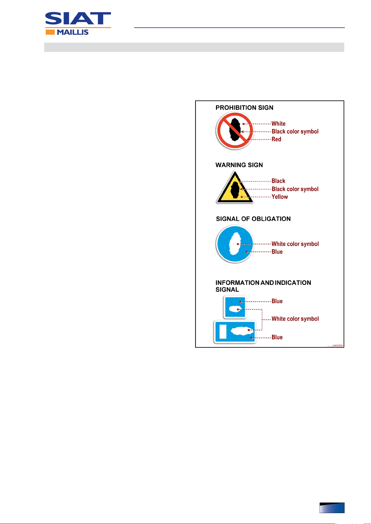
Safety and information symbols
– The information signals may be of different shapes and colours, to indicate dan-
gers, obligations, prohibitions and indications.
– The illustrations show the shapes of the signals that can be applied, with the
function indicated
– For more details on the type and position of the
signals applied, refer to the paragraph “Position
of safety signals and information”.
– Please keep safety signs and information legible
and follow the instructions.
– Signals which are no longer legible must be re-
placed and repositioned in the same place of origin.
Safety information
IDM 510-004-5
English languageOperation and maintenance manual
11

Safety information
12
English language Operation and maintenance manual
IDM 510-004-5

general description of the machine
Technical Specications
IDM 510-129-1
The semi-automatic wrapper series “ProWrap” is designed to secure products
loaded on pallets using stretch lm.
– To wrap loads, commercially available reels of stretch lm are used.
– The products to be wrapped must be contained in packages (cases, containers
for liquids, etc.) having a regular shape or in any case, such as to allow for stable
palletising.
– The containers of liquids or uids should be hermetically sealed and with suitable
characteristics to avoid spilling any content.
– The products to be wrapped have ALWAYS to be positioned in the middle and
must NOT protrude from the rotating platform in order to avoid the risk of collision.
– The wrapping surface shall be uniform and smooth (without projections or re-
cesses) in order to prevent the risk of lm breaking.
– The products are loaded and unloaded using forklift trucks of suitable capacity.
– Loading should ONLY be carried out from the orthogonal sides of the support
base (see gure).
– The machine has been designed, built and equipped by applying integrated safe-
ty principles.
– The machine is for professional use only and must be installed in industrial-type
settings - factories or workshops.
– The premises must have no areas with gas and dust concentration levels that are
potentially explosive and/or at risk of re.
English languageOperation and maintenance manual
13
Technical Specications
– On request, the machine may be equipped with accessories, either when it is
ordered or later.
See “Optional Accessories” for further details.
– The machine must be used by one single operator ONLY, who must be trained
and capable of performing the work and be in suitable conditions.
– The operator is in charge of programming and controlling the production cycle,
perform the relling and the scheduled maintenance.
IDM 510-129-1
14
English language Operation and maintenance manual
Technical Specications
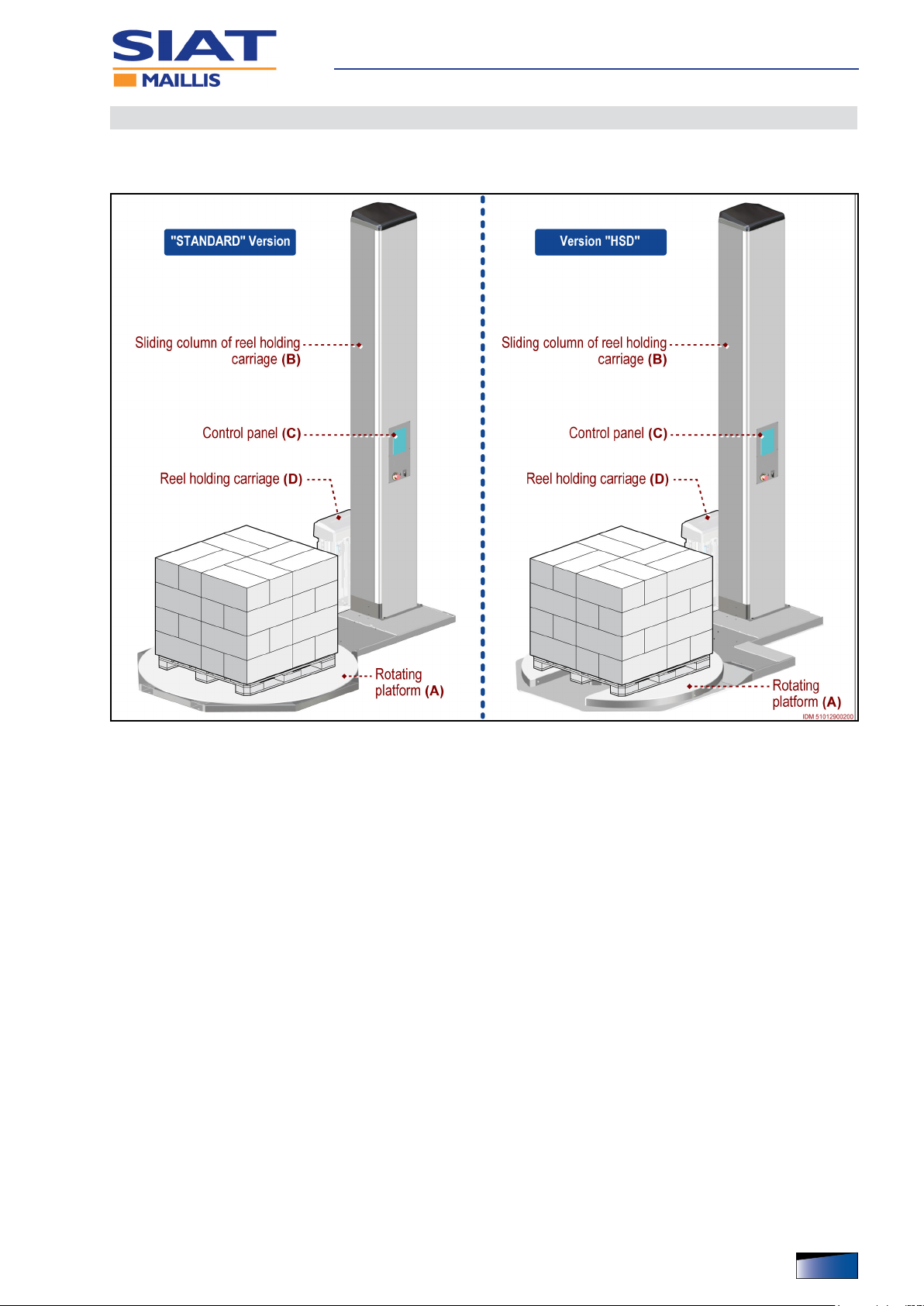
Description of the main components
The image shows the main components and the list reports their description
and function.
IDM 510-129-1
A) Rotating platform: area on which are loaded the products to be wrapped.
– The rotating platform is driven by a gear-motor with a chain drive.
B) Column: it is used for vertical movement of reel holding carriage D.
C) Control panel: it contains the devices to start and control all the operation func-
tions.
D) Reel holding carriage
– According to production requirements, in the ordering phase the machine can be
equipped with one of the listed carriages.
– Reel holder carriage (type M): suitable for wrapping, allows the operator to ad-
just the lm tension manually using the ring nut of the mechanical brake.
– Reel-holder carriage (type FM): suitable for wrapping, allows the operator to
adjust the lm tension from the control panel.
– Reel holding carriage (type PW): specic for wrapping with motorised lm
pre-stretching and transmission gear ratio adjustment (replacement of the pulleys).
English languageOperation and maintenance manual
15
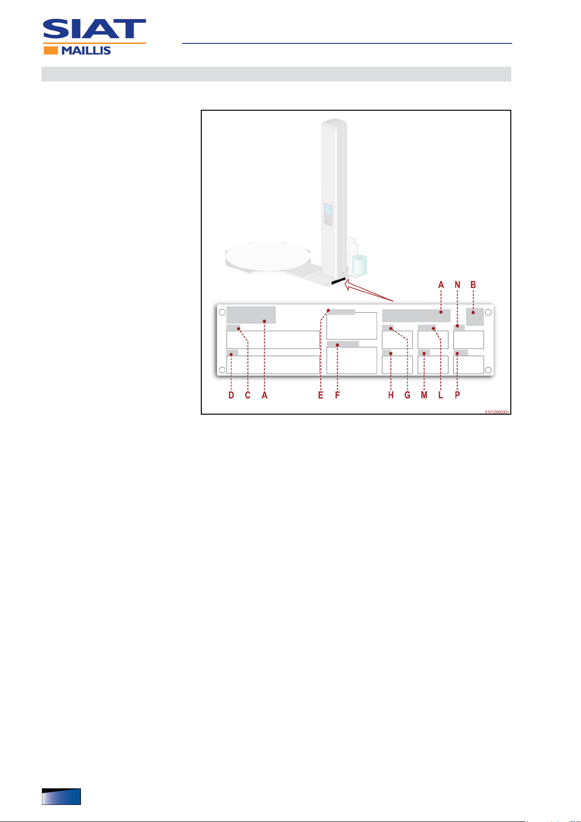
Manufacturer and machine identication
The identication plate (pictured) is afxed directly to the machine.
– In addition to the references for
identication provided by the
Manufacturer, they also list all
the essential information for a
safe operation.
A) Manufacturer identication
B) Space reserved for CE compli-
ance marking
C) Machine model
D) Machine type
E) Serial number
F) Serial number
G) Year of fabrication
Technical Specications
H) Power supply voltage
L) Electrical power consumption
M) Power supply frequency
N) Absorbed power
P) Power supply phases
16
English language Operation and maintenance manual
IDM 510-129-1
Technical Specications
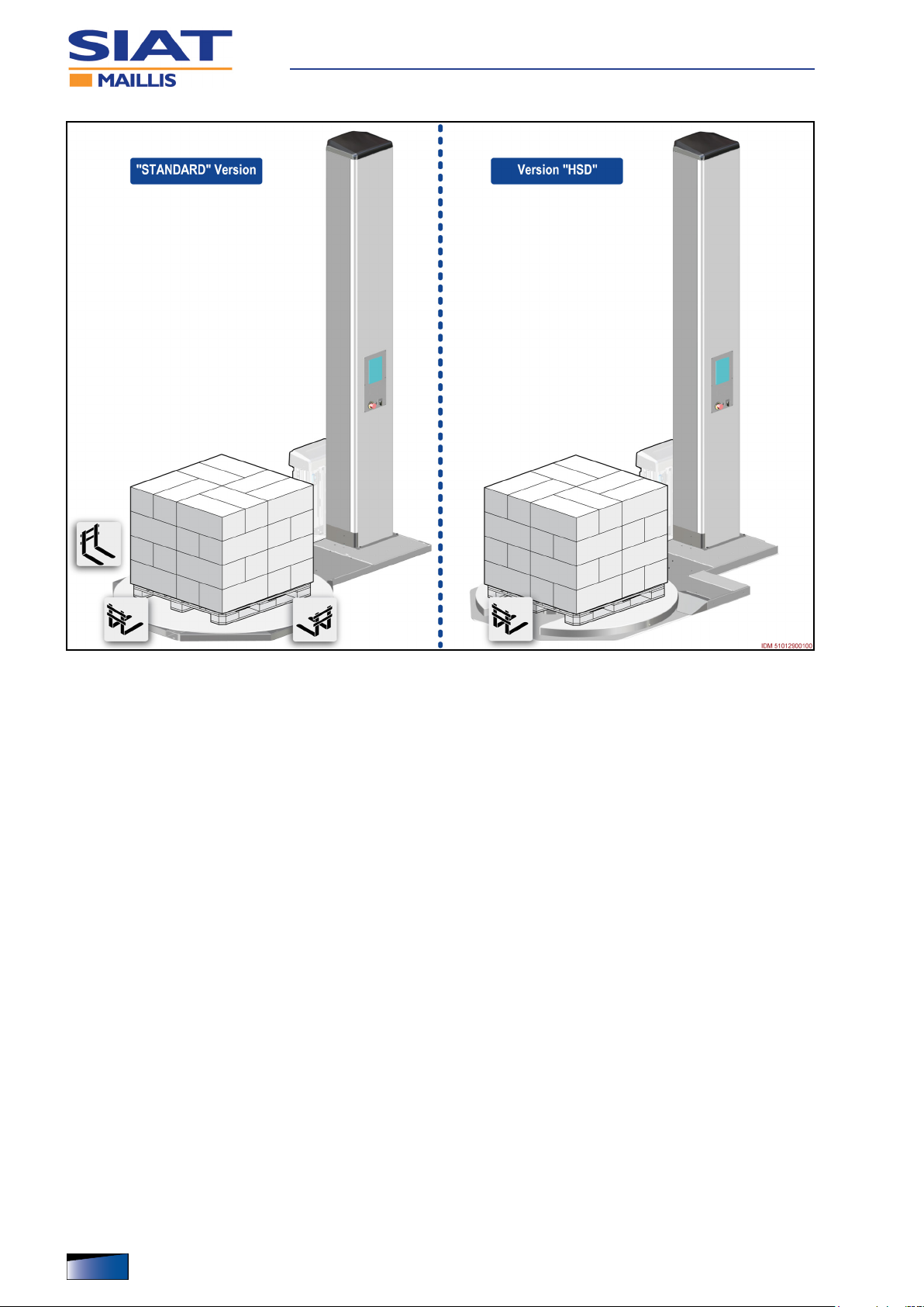
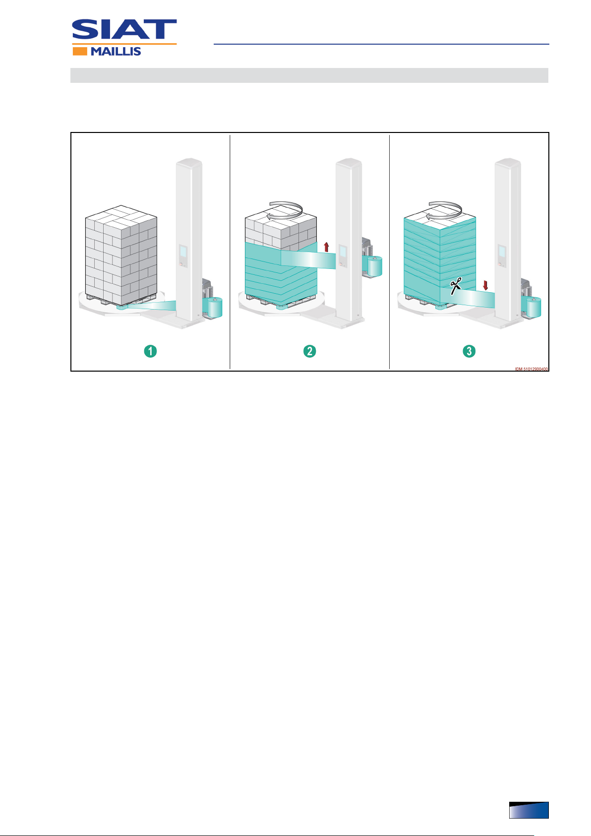
Cycle
The gure shows the operating cycle and indicates the main operating areas.
Stage Ê
– Correctly load the new product to be wrapped in the middle of rotating platform.
– Tie the trailing end of the lm to the base of the product to be wrapped.
Stage Ë
– Start the wrapping cycle that will be performed based on the previously set pa-
rameters.
– Manual wrapping: start the platform and keep the special control pressed to
start the wrapping process.
– Release control when wrapping has reached the desired height.
– Automatic wrapping: set up the desired parameters and press the special con-
trol to start the cycle.
– The machine carries out wrapping and at the end of the set-up cycle it stops au-
tomatically.
Stage Ì
– Manually cut the lm and cause it to adhere to the wrapped product.
– Remove the wrapped product to be able to load the next one to wrap.
– The machine is ready for a new wrapping cycle.
IDM 510-129-1
English languageOperation and maintenance manual
17
Technical Specications
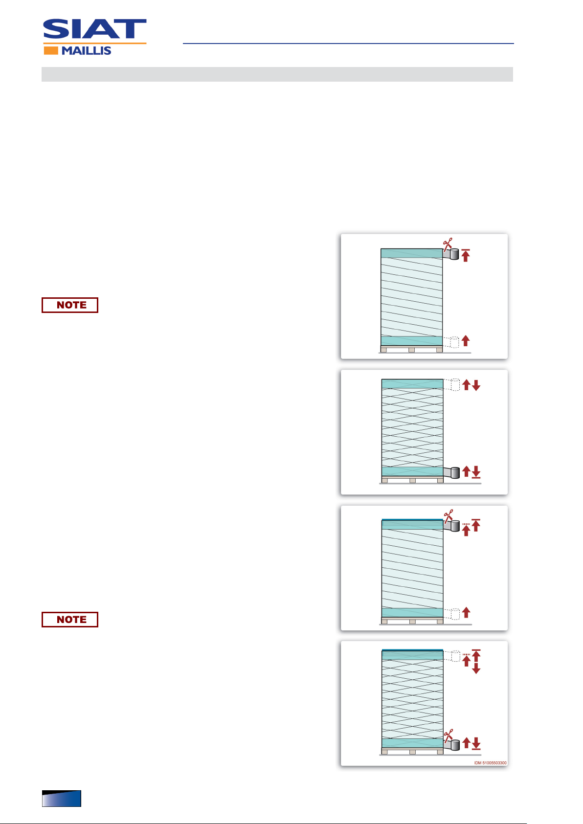
Types of wrapping
The wrapping can be made in manual or automatic mode.
– With the manual mode, platform rotates at a reduced speed, while reel holding
carriage is activated by a non-release control.
This mode allows for the wrapping to be made on an occasional basis, according
to the specications of the load to be wrapped (See “Control system.”).
– With the manual mode the wrapping can be programmed according to the spec-
ications of the load batch to be wrapped.
– The gures show the types of wrapping that can be programmed with the auto-
matic mode operation.
– Single wrapping: it starts at the base of the load to be wrapped
(with stabilisation wraps) and ends at the top of the load, after
completing the closing wrapping.
– Move the reel carriage to fully lowered position from the control
panel to start a new wrapping.
The operator can decide whether to cut the lm when the carriage is in the high position or in the low position.
– Double wrapping: it starts at the base of the load to be
wrapped (with stabilisation wraps) and ends at the top of the
load.
– After completing the reinforcement at the top of the load, the
wrapping continues downwards and stops after the closing
wrapping.
– Single wrapping with sheet feeder: it starts at the base of the
load to be wrapped (with stabilisation wraps) and stops temporarily at the top of the load.
– After inserting the covering sheet the operator must enable the
control to restart the wrapping.
– After completing the upper reinforcement, the wrapping stops.
– Move the reel carriage to fully lowered position from the control
panel to start a new wrapping.
The operator can decide whether to cut the lm when the carriage is in the high position or in the low position.
– Double wrapping with sheet feeder: it starts at the base of
the load to be wrapped (with stabilisation wraps) and stops
temporarily at the top of the load.
– After inserting the covering sheet the operator must enable the
control to restart the wrapping.
– After completing the reinforcement at the top of the load, the
wrapping continues downwards and stops after the closing
wrapping.
18
English language Operation and maintenance manual
IDM 510-129-1

Technical Specications
Residual risks
Residual risks are dened as: “Any risk that remains notwithstanding the safety
solutions adopted and integrated during the design phase”.
– Each residual risk is signalled with a special sign. Some of them are applied close
to the areas where the risk is present, others are placed in an easily visible position.
– The list includes the residual risks that may persist on this type of machine.
– Risk of projection of objects: during operation there may be a risk linked with
wrapping product stability characteristics in the event of excessive operation
speed.
– The operator must adjust the wrapping speed according to the product features
and during operation he/she shall not halt near the machine.
– Risk of slipping: do not climb onto or approach the platform during operation.
– Do not climb on the platform using the lifting equipment during operation.
– Risk of body part crushing: do not stand near and/or approach the area be-
tween the column and the product to be wrapped during operation.
– Risk of crushing upper limbs: do not introduce or place upper limbs in/next to
any machine moving parts during operation.
– Risk of crushing or shearing lower limbs: keep lower limbs away from the
platform during operation (fork inserting points version HSD).
– In addition to the precautions for the signalled risks, the following measures must
be implemented.
- Do NOT approach or allow people to approach the moving parts of the machine
in order to avoid dangerous collisions.
- When the lm is inserted, pay special attention in order to prevent collisions,
abrasion and crushing of the upper limbs.
IDM 510-129-1
English languageOperation and maintenance manual
19

Technical Specications
Incorrect uses that are reasonably expected
Improper use: reasonably foreseeable use different from what is specied in the
use manual, that may be caused by human behaviour.
– ONLY trained, documented and authorized Operators are allowed to use the ma-
chine.
– DO NOT use or allow other persons to use the machine for purposes and in ways
different from what specied by the Manufacturer.
– NEVER use the tool if the scheduled maintenance interventions have not been
carried out accordingly
– DO NOT use the machine in places that are at risk of re and / or explosion.
– When the products are wrapped, the radius of action of the machine must be kept
free from people.
– DO NOT carry out any intervention when the machine is being operated. Stop the
machine and put it in safety condition before carrying out any intervention.
– DO NOT clean or wash the machine using aggressive products that may damage
its components.
– DO NOT leave the machine unattended during operation and DO NOT leave it at
the end of the work without stopping it to safety conditions.
Optional Accessories
Some accessories designed to improve the performance and versatility of the
machine are available from the manufacturer. This list contains a description
of the main ones.
– Ramp: it makes product loading and unloading easier when a pallet truck driven
by a ground-level operator is used.
– Lifting frame: structure under the support base, used to load/unload the prod-
ucts to be wrapped by means of a “stackers”pallet truck.
– Burying frame: structure used to bury the support base of the machine.
– Weighing Unit: device used to weigh the palletised product located on the rotat-
ing platform.
– Pressing roller: this device keeps the product stabilised during wrapping.
20
English language Operation and maintenance manual
IDM 510-129-1
Technical Specications
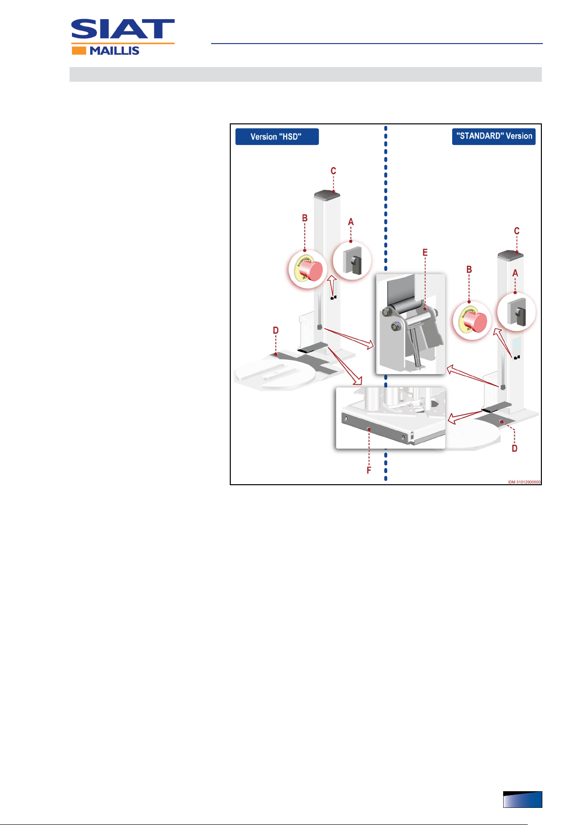
Description of the safety devices
The machine is equipped with safety devices that reduce the risks during the
man-machine interaction.
A) Isolator switch: safety control
to disconnect electric power
supply.
B) Emergency stop button:
safety control that, in case of an
imminent risk, stops all parts
whose function might constitute
a risk.
For further details on devices
A-B, refer to paragraph “Description of the controls.”
C) Fixed guard: safety device
that prevents access to the
parts whose operation may be
dangerous.
– The device is secured and it
can be opened only by means
of tools.
– Guard can be removed only
when the machine is stopped
under safe conditions and must
be installed before starting it.
D) Fixed guard: safety device
that prevents access to the
parts whose operation may be
dangerous.
– The device is secured and it
can be opened only by means of tools.
– Guard can be removed only when the machine is stopped under safe conditions
and must be installed before starting it.
E) Fall arrest system: safety device that prevents the risk of a fall of the carriage in
the event of lifting strap breaking.
– System is equipped with a spring device that locks the reel holding carriage after
a fall of 10 mm.
F) Feeler: safety device that stops the descent of the reel holding carriage in the
presence of an obstacle.
IDM 510-129-1
English languageOperation and maintenance manual
21
Technical data of machine
Technical Specications
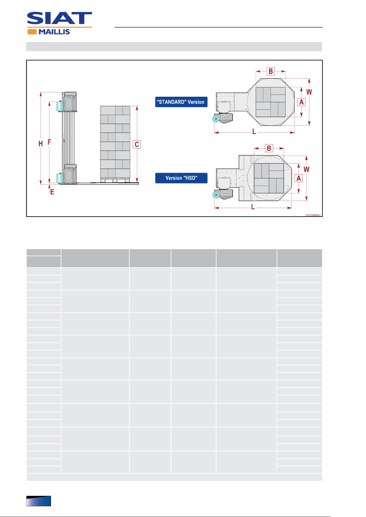
Dimensions and weights (Standard version)
▀
ProWrap
Model
16_L_FM
16_L_M 526
16_L_PW 549
16_M_FM
16_M_M 541
16_M_PW 564
16_H_FM
16_H_M 545
16_H_PW 568
18_L_FM
18_L_M 552
18_L_PW 575
18_M_FM
18_M_M 567
18_M_PW 590
18_H_FM
18_H_M 571
18_H_PW 594
22_L_FM
22_L_M 660
22_L_PW 683
22_M_FM
22_M_M 675
22_M_PW 698
22_H_FM
22_H_M 679
22_H_PW 702
Size of the load to be
wrapped AxBxC (mm)
Min 600x600x700
Max 1000x1200x2200
Min 600x600x700
Max 1000x1200x2600
Min 600x600x700
Max 1000x1200x3000
Min 600x600x700
Max 1200x1200x2200
Min 600x600x700
Max 1200x1200x2600
Min 600x600x700
Max 1200x1200x3000
Min 600x600x700
Max 1500x1500x2200
Min 600x600x700
Max 1500x1500x2600
Min 600x600x700
Max 1500x1500x3000
Weight of the
load to be
wrapped (kg)
Diameter of the
platform (mm)
Dimensions of the
machine LxWxH (mm)
xx ÷ 2400 1650 2831x1650x2714
xx ÷ 2400 1650 2831x1650x3114
xx ÷ 2400 1650 2831x1650x3514
xx ÷ 2400 1800 2982x1800x2714
xx ÷ 2400 1800 2982x1800x3114
xx ÷ 2400 1800 2982x1800x3514
xx ÷ 2400 2200 3382x2200x2714
xx ÷ 2400 2200 3382x2200x3114
xx ÷ 2400 2200 3382x2200x3514
Max weight of the
machine (kg)
526
541
545
552
567
571
660
675
679
Height above ground of the platform 75 mm
IDM 510-129-1
22
English language Operation and maintenance manual

Dimensions and weights (version HSD)
▀
Technical Specications
ProWrap
Model
HS_L_FM
HS_L_M 718
HS_L_PW 741
HS_M_FM
HS_M_M 733
HS_M_PW 756
16_M_FM
16_M_M 737
16_M_PW 760
Maximum size of the load to
be wrapped AxBxC (mm)
Min 600x600x700
Max 800x1200x2200
Min 600x600x700
Max 800x1200x2600
Min 600x600x700
Max 800x1200x3000
Max weight of
the load to be
wrapped (kg)
Diameter of the
platform (mm)
Dimensions of the
machine LxWxH (mm)
xx ÷ 1200 1650 2874x1736x2732
xx ÷ 1200 1650 2874x1736x3132
xx ÷ 1200 1650 2874x1736x3532
Max weight of the
machine (kg)
718
733
737
Height above ground of the platform 83 mm
Technical specications
▀
Unit of
measurement
Value
OPERATING PROPERTIES
Height of wrapping start E mm 20 ÷ 120
Height of wrapping end F
- Model L mm 2400
- Model M mm 2800
- Model H mm 3200
Rotation speed of the platform rpm 6 ÷ 12
Maximum level of noise dB(A) 72.0
Electric supply
The power supply specications are those shown in the identication plate
applied to the machine.
- -
- With single-phase power supply: install a circuit breaker “A” in the line. - -
- With three-phase power supply: install a circuit breaker “B” in the line. - -
Electric protection class - IP 54
Environmental conditions
Maximum operating height (asl) m 1000
Relative humidity (detected at a temperature included between 20°C and 40°C) - 80%
Ambient functioning temperature °C +5 ÷ 40
Environmental brightness LUX 150
IDM 510-129-1
Technical specications of pressing roller
▀
Unit of
measurement
Value
Weight kg Operating pressure bar 6
Air consumption at the working pressure
- Model L Nl/cycle 9,32
- Model M Nl/cycle 11,77
- Model H Nl/cycle 13,73
Height of the load to be wrapped
- Model L mm 1500 ÷ 2200
- Model M mm 1600 ÷ 2600
- Model H mm 1800 ÷ 3000
Height of the load to be wrapped (with optional extension)
- Model L mm 750 ÷ 2200
- Model M mm 850 ÷ 2600
- Model H mm 1050 ÷ 3000
English languageOperation and maintenance manual
23
Specications of the accessories available on request
▀
Technical Specications
Unit of
measurement
Weight Capacity
Ramp kg 58 1000
Weighing unit kg 260 2000
Floating weighing unit kg 270 2000
Lifting frame kg 260 2000
Burying frame kg 150 -
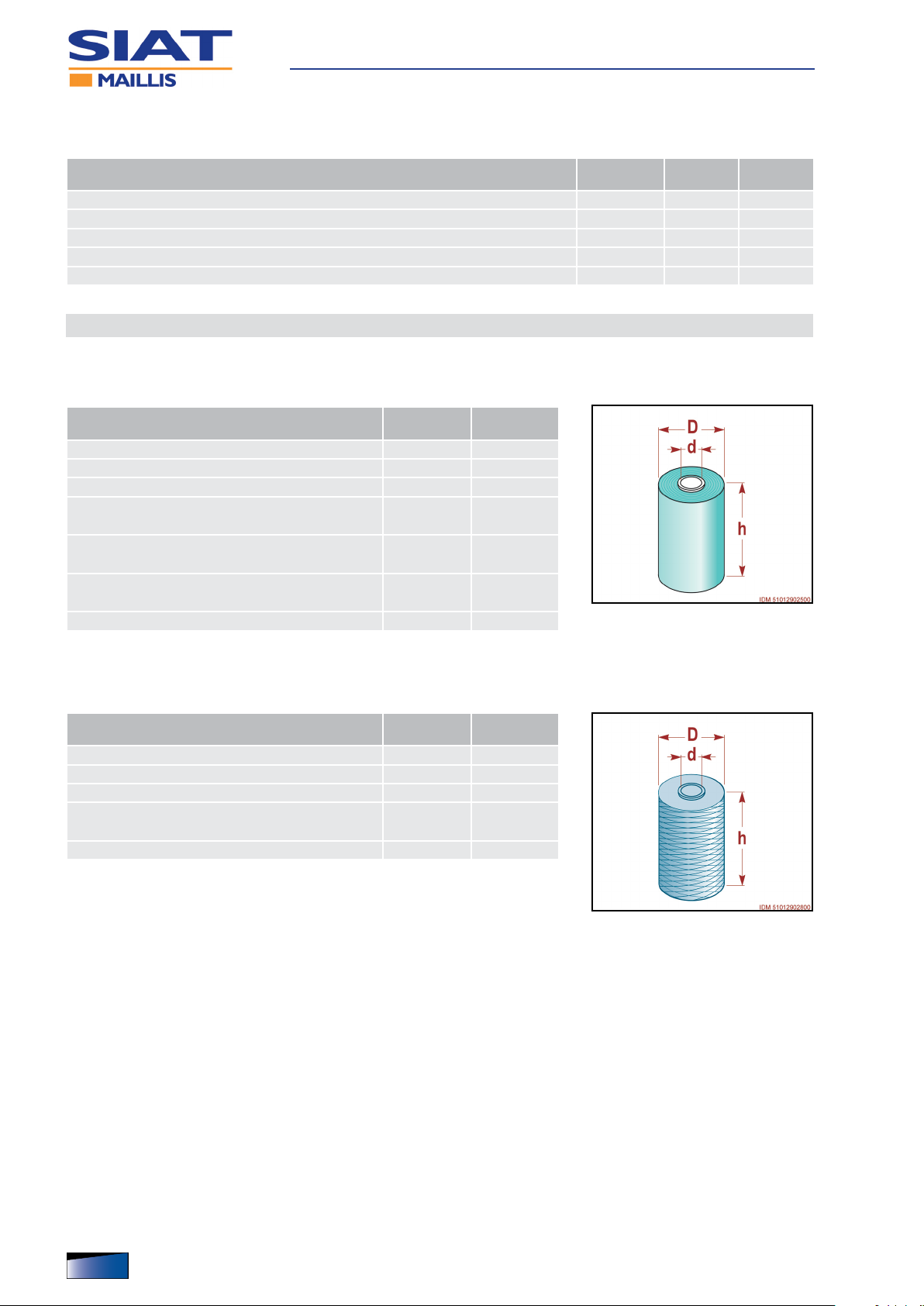
Technical data of reel
Dimensions of lm reel
▀
Unit of
measurement
Maximum external diameter D mm 250
Inside Diameter d mm 76
Maximum height h mm 500
Maximum height h (Machine with reel holding
carriage of type PW750).
Film thickness (Machine with reel holding
carriage of type EM - M - FM).
Film thickness (Machine with reel holding
carriage of type PW - DM).
mm 750
µm 9-12-17-23
µm 17 ÷ 23
Max Weight kg 17
Value
Net reel dimensions
▀
Unit of
measurement
Value
Maximum external diameter D mm 250
Inside Diameter d mm 76
Maximum height h mm 500
Maximum height h (Machine with reel holding
carriage of type PW750).
mm 750
Max Weight kg 17
IDM 510-129-1
24
English language Operation and maintenance manual
Technical Specications
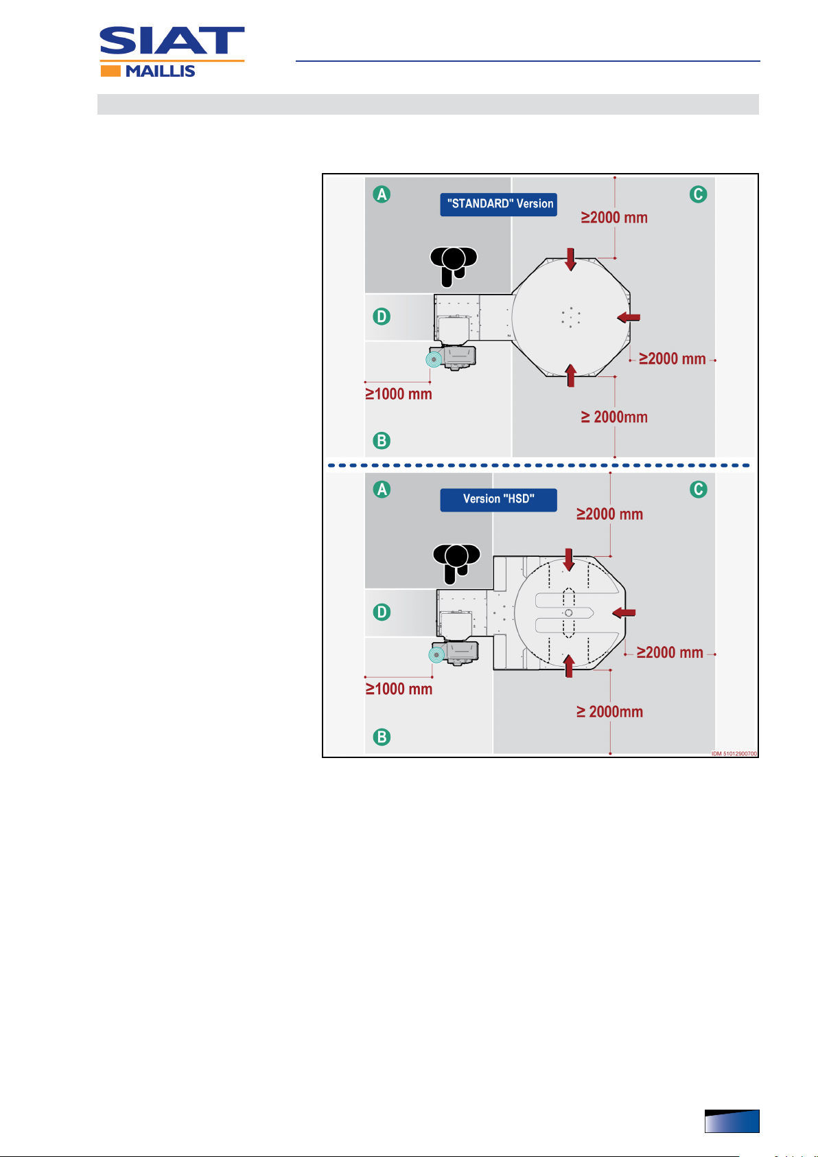
Description of outer areas
The gure shows different areas to be considered in the planning of the installation area.
A) Operator control and stand-
ing area
B) Rell area for reel
C) Loading/unloading area for
the products to be wrapped
D) Perimeter area
IDM 510-129-1
English languageOperation and maintenance manual
25
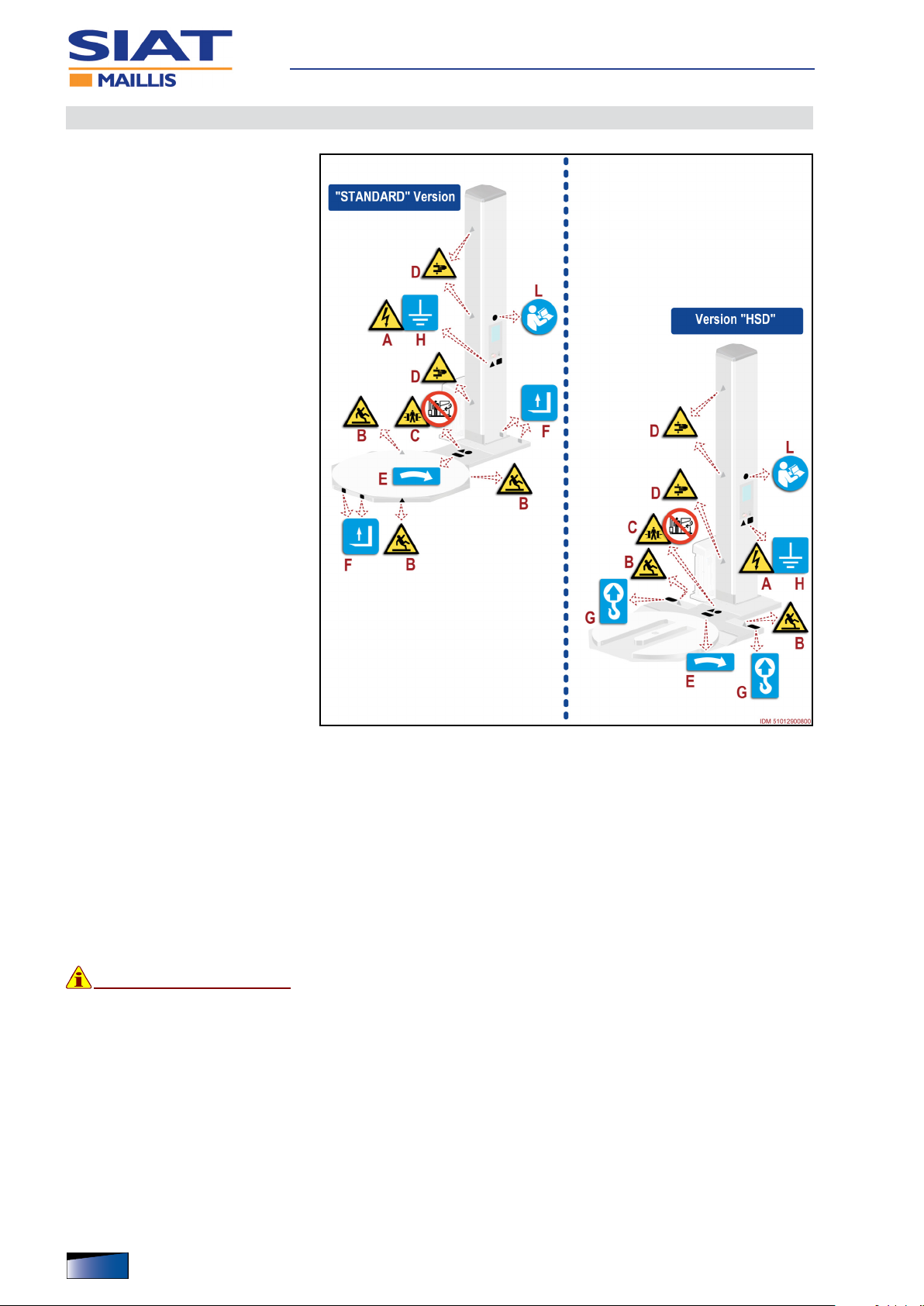
Safety and information symbols
The gure shows the applied
signals and the list includes the
description of the shown residual risk.
A) Electrical shock or electrocu-
tion hazard: hazard signal that
warns the operator from accessing the areas under voltage in order to avoid risks.
B) Risk of slipping: danger sig-
nal indicating that attention
should be paid during transfers
on at surfaces.
C) Risk of crushing body parts:
danger signal warning to stay
out of the active machine work
range.
Technical Specications
D) Risk of crushing upper limbs:
danger signal warning to keep
upper limbs out of the active
machine work range.
E) Information Signal: indicates
the required direction of rotation for operation.
F) Information Signal: indicates
the lifting points for fork-type
devices.
G) Information sign: it indicates the points where to attach the hooks of the lifting
device.
H) Information Signal: indicates the earthing point.
L) Information warning sign: read the operation and maintenance manual careful-
ly before performing any operations.
– Please keep safety signs and information legible and follow the instructions.
– Signals which are no longer legible must be replaced and repositioned in the
same place of origin.
Important
At the time of ordering provide the code of each signal to be replaced that is
specied in the spare parts catalogue.
26
English language Operation and maintenance manual
IDM 510-129-1

Recommendations for maintenance interventions
– The recommendations represent a summary of those shown in the SAFETY
WARNINGS section.
– The personnel authorized to carry out the ordinary maintenance must have qual-
ied expertise and specic skills in the eld of intervention.
– Any work on the electrical system must ONLY be performed by technicians with
acknowledged, eld-specic skills.
– Mark the intervention area and prevent access to the devices that, if activated,
may cause unexpected hazards and jeopardize the safety level.
– According to the type of operation to carry out, wear the Personal Protective
Equipment listed in the “Instructions for use” and that indicated by the Labour
laws.
– Before carrying out any intervention, activate all the safety measures, and assess
any residual energy which may still be present.
– Carry out the interventions ONLY according to the modes recommended by the
Manufacturer in the “Instructions for use”.
Maintenance
– All operations must be carried out ONLY with suitable tools which shall be in good
condition, in order to avoid damaging any components and parts of the machine.
– At work completion, restore all the security conditions aimed to prevent and min-
imize the risks during the human-machine interaction.
– At the end of operations check that there are no other tools or other material near
the moving parts or in dangerous areas.
– Refer to the Technical Assistance Service of the Manufacturer, in case interven-
tions not described in the “Instructions for use” are needed.
– In order to avoid safety hazards for the operators and nancial losses, fol-
low not only the recommendations but also the information in the SAFETY
WARNINGS section.
IDM 510-129-1
English languageOperation and maintenance manual
27
Scheduled maintenance intervals
Att
Att
Always keep the machine in optimum operating condition and carry out the
routine maintenance according to the intervals and procedures specied by
the Manufacturer.
– In case of prolonged inactivity, carry out some maintenance operations in order
to preserve functionality and prevent further damages.
– After prolonged inactivity, carefully check that the operating functionality has re-
mained unaltered.
– A good maintenance will ensure a stable performance over time, longer working
life and constant compliance with the safety requirements.
Maintenance schedule
Every working day
Component Operation required Procedures to implement
- Make sure that the listed devices are efficient.
Safety devices Checking
- Emergency stop button.
- Main electric disconnector
Maintenance
Every 40 work hours (max 1 week)
Component Operation required Procedures to implement
Lifting belt for the reel holding carriage Checking
Reel holding carriage sliding guides Cleaning
Load to be wrapped detection photocell Cleaning
Every 2000 work hours (max 6 months)
Component Operation required Procedures to implement
Air lter (if any) Cleaning
Checking
Rotating platform rotation chain
Lubrication
Film pre-stretch belt (Only for reel holding
carriages of type PW).
Film drawing-in rollers (Only for reel
holding carriages of type PW).
Checking
Cleaning
- Check this component for wear.
- Replace the belt in case it is excessively worn. (See
“Replacing the lifting belt of the carriage”).
- Remove any impurities with a plastic scraper.
- Clean with a soft cloth soaked in a non-flammable
and non-corrosive detergent.
- Properly dry the surfaces.
ention
Warning
Do not use water jets.
- Clean the detection area of the photocell.
- Use a clean, dry (not abrasive) cloth.
- Clean the filter or replace it with an original spare
part, if necessary (See “Cleaning and replacement of
the air filter”).
- Check the tension of component.
- Adjust tension as required - if necessary (See
“Adjustment of chain controlling the rotation of
platform”).
- Lubricate all the greasing points (See “Diagram of
the points of lubrication”).
- Check the tension of component.
- Adjust tension as required - if necessary (See
“Adjustment of drive chain tensioning”).
- Replace the belt in case it is excessively worn.
- Clean with a soft cloth soaked in a non-flammable
and non-corrosive detergent.
- Properly dry the surfaces.
ention
Warning
Do not use water jets.
IDM 510-129-1
28
English language Operation and maintenance manual

Every 5000 work hours (max 12 months)
Component Operation required Procedures to implement
Vertical movement wheels of the reel
holding carriage
Rotation wheels of rotating platform Checking
Checking
- Check this component for wear.
- Replace the component, if it is worn out
- Check this component for wear.
- Replace the component, if it is worn out
Diagram of the points of lubrication
Lubricate the parts indicated according to the frequency and methods shown.
– Use the lubricants (oils and
greases) recommended by the
Manufacturer or lubricants of
equivalent chemical and physical characteristics.
– Some components (reducers,
bearings, etc.) do not request
lubrication because they are
self-lubricating or life lubricated.
Maintenance
– If the ambient temperature is in-
cluded between -10°C and
+35°C, use lubricants with SAE
20 ISO VG50 or SAE 50 ISO
VG 300 viscosity grade.
If the ambient temperature is not
included in the indicated range,
contact the Manufacturer for
more information on the type of
lubricant to be used.
IDM 510-129-1
English languageOperation and maintenance manual
29

Problems, causes, remedies
The table shows the list of faults that can occur during the standard operation
and it highlights possible remedies.
Table: Operation failures
Problem Cause Remedy
- Identify the causes that have caused
With isolator switch G on ON, pilot
light does not turn off when button F is
pressed.
When button Start B is pressed, the
rotating platform does not start.
The reel holding carriage will not go
up.
The reel holder carriage raises but
does not stop at the top of the load to
be wrapped.
The ends of the load are wrapped with
an excessive amount of reinforcing
bands.
The lm is too tightly stretched or too
loose.
Emergency stop button pressed
The photocell did not detect the load
to be wrapped
Rotating platform not correctly timed. - Press key D.
The photocell did not detect the load
to be wrapped
Reel holding carriage not correctly
timed.
Top limit stop detecting microswitch
failure
Failure of the inverter of the reel
holding carriage
The photocell did not detect the load
to be wrapped
Top reinforcing band quantity not
correctly set
Bottom reinforcing band quantity not
correctly set
Tension of lm not properly adjusted - Adjust the tension of film.
the stop.
- Restore normal running conditions
- Unlock the emergency stop button
with a voluntary action.
- Check the functionality of the
component.
- The component must be adjusted
(See “Sensitivity adjustment for the
product to be wrapped detection
photocell”).
- Check the functionality of the
component.
- The component must be adjusted
(See “Sensitivity adjustment for the
product to be wrapped detection
photocell”).
- Press key D.
- Check the functionality of the
component.
- The component must be adjusted.
- Check the error code.
- Check the functionality of the
component.
- The component must be adjusted
(See “Sensitivity adjustment for the
product to be wrapped detection
photocell”).
- Modify the programming.
- Modify the programming.
Maintenance
30
English language Operation and maintenance manual
IDM 510-129-1

Problem Cause Remedy
The machine stops with the reel
holding carriage not correctly
positioned.
Rotating platform jogging motion.
The noise level is too high.
Reel holding carriage jogging motion.
Presence of residues or dust on the
reel holding carriage sliding guides
There is an obstacle under the reel
holder carriage.
Braking or excessive wear of the reel
holder carriage lifting belt
Rotating platform rotation chain not
properly tensioned
Presence of residues or dust on the
wheels
Rotating platform rotation chain not
properly tensioned
Wheels of rotating platform worn out
or damaged
Failure of gearmotor driving the
rotating platform
Presence of residues or dust on the
reel holding carriage sliding guides
Maintenance
- Remove any residues.
Use brushed with soft plastic bristles.
Press key D.
- Remove the obstacle.
Press key D.
- Replace belt (See “Replacing the
lifting belt of the carriage”).
- The component must be adjusted
(See “Adjustment of chain controlling
the rotation of platform”).
- Remove any residues.
Use brushed with soft plastic bristles.
- The component must be adjusted
(See “Adjustment of chain controlling
the rotation of platform”).
- Replace the component.
- Check the functionality of the
component.
- Remove any residues.
Use brushed with soft plastic bristles.
IDM 510-129-1
English languageOperation and maintenance manual
31

Maintenance
Alarm message table
no. Type of failure Remedy
Machine alarms
Sensor does not detect the rotation of
01
platform.
(Lower and upper) sensors do not detect the
02
end of stroke of the reel holding carriage.
Failure of the relays that power the inverter
03
power circuit.
The carriage drive chain is not correctly
05
tensioned.
The photocell does not detect any load to be
06
wrapped.
Elements that prevent the correct detection are
07
between sensors of the rotating platform
(version HSD).
08 The lm reel is exhausted. - Replace reel (See “Film Coil Feeding”).
Rotating platform inverter alarms
The inverter parameters are not properly set
10
up.
The activation of the inverter electric power is
11
not correctly enabled.
The electric motor is damaged due to a short
12
circuit.
The heat protection is damaged because of
13
the overheating of the electric motor.
14 Inverter bis power circuit failure. - Contact the Manufacturer’s Technical Assistance Service.
15 Inverter module failure due to overheating.
Overvoltage of the hardware electric power
16
supply (higher than 4 A).
Communication was interrupted because of an
17
internal error.
- Check the connections and/or the position of sensor.
- Press control F to silence the alarm.
- Check the connections and/or the position of sensors.
- Press control F to silence the alarm.
- Press control F or turn the power of the electronic board off and on to
silence the alarm.
- If the problem persists, disconnect the electric power and contact the
Manufacturer’s Technical Assistance Service.
- Make sure that the reel holding carriage can move freely and without
obstacles.
- Check the connections and/or the position of the photocells.
- Press control F to silence the alarm.
- Control D lights up.
- Press control D.
Reel holding carriage moves upwards and then it moves downwards
again in order to phase the operating units.
- Make sure that the load to be wrapped is properly positioned.
- Check the connections and/or the position of the photocell.
- Remove the obstacles.
- Make sure that the load to be wrapped is positioned on the rotating
platform.
- Check the connections and/or the position of the photocells.
- Contact the Manufacturer’s Technical Assistance Service.
- Contact the Manufacturer’s Technical Assistance Service.
- Contact the Manufacturer’s Technical Assistance Service.
- Let the motor cool down.
- Press control F or deactivate and re-activate power (even more than
once) to silence the alarm.
- If the problem persists, disconnect the electric power and contact the
Manufacturer’s Technical Assistance Service.
- Check if the fan system works properly and if there are obstacles in the
air flow.
- If the problem persists, disconnect the electric power and contact the
Manufacturer’s Technical Assistance Service.
- Contact the Manufacturer’s Technical Assistance Service.
- Contact the Manufacturer’s Technical Assistance Service.
IDM 510-129-1
32
English language Operation and maintenance manual

Maintenance
no. Type of failure Remedy
Reel holder carriage inverter alarms
The inverter parameters are not properly set
20
up.
The activation of the inverter electric power is
21
not correctly enabled.
The electric motor is damaged due to a short
22
circuit.
The heat protection is damaged because of
23
the overheating of the electric motor.
24 Inverter bis power circuit failure. - Contact the Manufacturer’s Technical Assistance Service.
25 Inverter module failure due to overheating.
Overvoltage of the hardware electric power
26
supply (higher than 4 A).
Communication was interrupted because of an
27
internal error.
- Contact the Manufacturer’s Technical Assistance Service.
- Contact the Manufacturer’s Technical Assistance Service.
- Contact the Manufacturer’s Technical Assistance Service.
- Let the motor cool down.
- Press control F or deactivate and re-activate power (even more than
once) to silence the alarm.
- If the problem persists, disconnect the electric power and contact the
Manufacturer’s Technical Assistance Service.
- Check if the fan system works properly and if there are obstacles in the
air flow.
- If the problem persists, disconnect the electric power and contact the
Manufacturer’s Technical Assistance Service.
- Contact the Manufacturer’s Technical Assistance Service.
- Contact the Manufacturer’s Technical Assistance Service.
IDM 510-129-1
English languageOperation and maintenance manual
33

Cleaning and replacement of the air lter
Att
The operation must be carried out by the maintenance technician or by personnel with suitable competences, skills and knowledge.
Make sure to full the required requirements in order to work under safe conditions.
– The intervention must be carried out with the machine stopped in safety condi-
tions.
– The gure shows the points of intervention and the description shows the proce-
dures to be adopted.
1. Mark the intervention area and
prevent access to the devices
that, if activated, may cause
unexpected hazards and jeopardize the safety level.
ention
Warning
Always wear suitable personal
protective equipment in order to
avoid safety and health hazards.
Maintenance
2. Rotate main disconnector to
position “O” (OFF) to deactivate the power supply.
3. Unhook the grid A.
4. Remove the lter B.
5. Clean the lter with dry com-
pressed air.
Replace the lter with an original spare part, if it is damaged.
6. Re-install the lter B.
7. Attach the grid A.
– At the end of operations,
check that there are no tools
or other material near the
moving parts or in dangerous areas.
34
English language Operation and maintenance manual
IDM 510-129-1

Adjustment of chain controlling the rotation of platform
Att
The operation must be carried out by the maintenance technician or by personnel with suitable competences, skills and knowledge.
Make sure to full the required requirements in order to work under safe conditions.
– This service should be carried out with the reel holding carriage lowered and the
machine safely at a stop.
– The gure shows the points of intervention and the description shows the proce-
dures to be adopted.
1. Mark the intervention area and
prevent access to the devices
that, if activated, may cause
unexpected hazards and jeopardize the safety level.
ention
Warning
Always wear suitable personal
protective equipment in order to
avoid safety and health hazards.
Maintenance
2. Rotate main disconnector to
position “O” (OFF) to deactivate the power supply.
3. To reach high, not easily accessible or otherwise hazardous
areas, implement adequate
safety measures to avoid risks.
4. Disassemble the pressing roller
(See “Disassembly and re-assembly of the Pressing Roller”).
5. Disassemble the reel holding
carriage (See “Disassembly
and re-assembly of the reel
holding carriage”).
Important
Only for reel holding carriages
of type PW
1°
6. Remove the fastening elements A and remove the component B.
IDM 510-129-1
2°
7. Attach the column C to a lifting device.
3°
8. Disassemble the guards K-W.
9. Loosen the screws D.
English languageOperation and maintenance manual
35

4°
10. Bring the column to a horizontal
position.
– Insert the shim E under the
column to keep it horizontal.
5°
11. Slightly loosen the nuts F.
12. Adjust the tension of chain G by
means of the adjusting system
H.
Important
Do not overtighten so as not to
cause any malfunctioning.
13. Tighten the nuts F.
6°
14. Lift the column to its vertical position.
Maintenance
15. Introduce and tighten the
screws D.
16. Remove the lifting device.
17. Re-install the guards K-W.
7°
18. Install the component B and
lock it in place with the fastening elements A.
19. Install the reel holding carriage
(See “Disassembly and re-assembly of the reel holding carriage”).
Important
Only for reel holding carriages
of type PW
20. Install the pressing roller (See
“Disassembly and re-assembly
of the Pressing Roller”).
– At the end of operations,
check that there are no tools
or other material near the
moving parts or in dangerous areas.
21. Start the machine and make
sure that the operation has
been carried out properly.
36
English language Operation and maintenance manual
IDM 510-129-1

Maintenance
Sensitivity adjustment for the product to be wrapped detection photocell
The operation must be carried out by the maintenance technician or by personnel with suitable competences, skills and knowledge.
Make sure to full the required requirements in order to work under safe conditions.
– The sensitivity adjustment is required when the photocell does not detect the
presence of the load to be wrapped.
– The gure shows the points of intervention and the description shows the proce-
dures to be adopted.
1. Mark the intervention area and
prevent access to the devices
that, if activated, may cause
unexpected hazards and jeopardize the safety level.
2. Correctly load the new product
to be wrapped in the middle of
rotating platform.
3. Move the reel holder carriage
to match the load to be
wrapped.
4. Check if the photocell detects
the load to be wrapped.
– The light A lighting up (green
light) indicates that the photocell is powered.
– When pilot light B turns on (yel-
low light), it means that the load
to be wrapped has been detected.
– When the light B is off, slowly
rotate the control C until the indicator light illuminates.
Do NOT adjust the photocell
sensibility excessively in order
to prevent it from detecting elements that are not to be wrapped.
The detection of elements that are not to wrapped can alter the point of stop of
reel holding carriage.
IDM 510-129-1
English languageOperation and maintenance manual
37

Replacing the rotating platform wheels (standard version)
Att
The operation must be carried out by the maintenance technician or by personnel with suitable competences, skills and knowledge.
Make sure to full the required requirements in order to work under safe conditions.
– This service should be carried out with the reel holding carriage lowered and the
machine safely at a stop.
– The gure shows the points of intervention and the description shows the proce-
dures to be adopted.
1. Mark the intervention area and
prevent access to the devices
that, if activated, may cause
unexpected hazards and jeopardize the safety level.
ention
Warning
Always wear suitable personal
protective equipment in order to
avoid safety and health hazards.
Maintenance
2. Rotate main disconnector to
position “O” (OFF) to deactivate the power supply.
3. Loosen the screws A.
4. Fit the eyebolt on the rotating
platform.
5. Attach the lifting device to the
eyebolt.
6. Lift and move the rotating platform on the side.
7. One at a time, remove all the
wheels B.
8. One at a time, t all the new
wheels.
Important
Replace the components ONLY
with GENUINE SPARE PARTS or with other components of equivalent design
and functional specications.
9. Adjust the platform in its original position.
10. Remove the lifting device.
11. Remove the eyelet.
12. Tighten the screws A.
– At the end of operations, check that there are no tools or other material
near the moving parts or in dangerous areas.
13. Start the machine and make sure that the operation has been carried out proper-
ly.
38
English language Operation and maintenance manual
IDM 510-129-1

Replacing the rotating platform wheels (version HSD)
Att
The operation must be carried out by the maintenance technician or by personnel with suitable competences, skills and knowledge.
Make sure to full the required requirements in order to work under safe conditions.
– This service should be carried out with the reel holding carriage lowered and the
machine safely at a stop.
– The gure shows the points of intervention and the description shows the proce-
dures to be adopted.
1. Mark the intervention area and
prevent access to the devices
that, if activated, may cause
unexpected hazards and jeopardize the safety level.
ention
Warning
Always wear suitable personal
protective equipment in order to
avoid safety and health hazards.
Maintenance
2. Rotate main disconnector to
position “O” (OFF) to deactivate the power supply.
3. Disconnect all connectors from
their sensors.
4. Fit the eyebolts on the rotating
platform.
5. Set up a hook-shaped lifting
device with a suitable capacity.
6. Hook the lifting device using
the eyelets.
7. Lift the rotating platform A and
place it on supports to facilitate
the operation.
Important
The lifting device must be kept
tensioned, to avoid sudden falls and the associated body parts crushing risks.
8. One by one, undo the retaining springs B and remove the wheels C.
9. One at a time, t all the new wheels and fasten the retaining springs B.
IDM 510-129-1
10. Check the integrity of the bearing E and, if necessary, replace it.
Important
Replace the components ONLY with GENUINE SPARE PARTS or with other
components of equivalent design and functional specications.
English languageOperation and maintenance manual
39

11. Slightly lift the platform , remove the supports and reposition it on the base.
– During repositioning, be
careful that the pin of the
platform properly engages in
bearing E.
12. Remove the lifting device.
13. Remove the eyebolts
14. Connect the connectors to their
sensors.
– At the end of operations,
check that there are no tools
or other material near the
moving parts or in dangerous areas.
Maintenance
15. Start the machine and make
sure that the operation has
been carried out properly.
40
English language Operation and maintenance manual
IDM 510-129-1

Replacing the lifting belt of the carriage
Att
The operation must be carried out by the maintenance technician or by personnel with suitable competences, skills and knowledge.
Make sure to full the required requirements in order to work under safe conditions.
– This service should be carried
out with the reel holding carriage lowered and the machine
safely at a stop.
– The gure shows the points of
intervention and the description
shows the procedures to be
adopted.
1. Mark the intervention area and
prevent access to the devices
that, if activated, may cause
unexpected hazards and jeopardize the safety level.
ention
Warning
Always wear suitable personal
protective equipment in order to
avoid safety and health hazards.
Maintenance
2. Rotate main disconnector to
position “O” (OFF) to deactivate the power supply.
3. To reach high, not easily accessible or otherwise hazardous
areas, implement adequate
safety measures to avoid risks.
4. Disassemble the pressing roller
(See “Disassembly and re-assembly of the Pressing Roller”).
5. Disassemble the reel holding
carriage (See “Disassembly
and re-assembly of the reel
holding carriage”).
Important
Only for reel holding carriages
of type PW
1°
6. Remove the fastening elements A and remove the component B.
2°
7. Attach the column C to a lifting device.
IDM 510-129-1
3°
8. Remove the guard W.
9. Loosen the screws D.
4°
10. Bring the column to a horizontal position.
– Insert the shim E under the column to keep it horizontal.
English languageOperation and maintenance manual
41

5°
11. Remove the fastening elements and remove the component K.
12. Disconnect all connectors from
their sensors.
13. Slip out pin F.
6°
14. Partially remove the reel holder
carriage to reach the fastening
elements.
7°
15. Remove the fasteners G.
16. Remove the bushing H and re-
move the damaged belt L.
17. Insert the bushing H in the new
belt.
Maintenance
Important
Replace the components ONLY
with GENUINE SPARE PARTS or
with other components of equivalent design and functional
specications.
18. Secure the end of the belt (with
bushing) by means of the fastening elements G.
19. Remount the reel holder carriage.
8°
20. Lead the belt over the roller M.
21. Insert the pin F to connect the
end of the belt to the pulley N.
42
English language Operation and maintenance manual
IDM 510-129-1

9°
22. Install the component K and
lock it in place with the fastening elements.
23. Connect the connectors to their
sensors.
24. Keep the belt taut and move
the reel holder carriage to
match the base of the column.
10°
25. Lift the column to its vertical position.
26. Introduce and tighten the
screws D.
27. Remove the lifting device.
28. Install the guard W.
Maintenance
11°
29. Install the component B and
lock it in place with the fastening elements A.
30. Install the reel holding carriage
(See “Disassembly and re-assembly of the reel holding carriage”).
Important
Only for reel holding carriages
of type PW
31. Install the pressing roller (See
“Disassembly and re-assembly
of the Pressing Roller”).
– At the end of operations, check that there are no tools or other material
near the moving parts or in dangerous areas.
32. Start the machine and make sure that the operation has been carried out proper-
ly.
IDM 510-129-1
English languageOperation and maintenance manual
43

Description of the main components of the Pressing Roller
The Pressing Roller keeps the product stabilised during wrapping.
A) Pressing roller disc: it rests
on the product to keep it stable.
B) Pneumatic actuator: it is used
to vertically move the pressing
roller disc.
Pressing roller
44
English language Operation and maintenance manual
IDM 510-129-1

Disassembly and re-assembly of the Pressing Roller
Att
The operation must be carried out by the maintenance technician or by personnel with suitable competences, skills and knowledge.
Make sure to full the required requirements in order to work under safe conditions.
– This service should be carried out with the reel holding carriage lowered and the
machine safely at a stop.
– The gure shows the points of
intervention and the description
shows the procedures to be
adopted.
1. Mark the intervention area and
prevent access to the devices
that, if activated, may cause
unexpected hazards and jeopardize the safety level.
ention
Warning
Wear the suitable personal protective equipment (gloves and
shoes) to avoid any abrasion
and/or crushing hazard.
Pressing roller
2. Rotate main disconnector to
position “O” (OFF) to deactivate the power supply.
3. Disconnect the pneumatic supply
4. To reach high, not easily accessible or otherwise hazardous
areas, implement adequate
safety measures to avoid risks.
5. Loosen the screws A and re-
move the cover B.
6. Loosen the screws C and re-
move the component D.
7. Disconnect the electric and
pneumatic connections.
8. Loosen the screwsE and disassemble the front panel F.
9. Loosen the screws G.
10. Loosen the screws H.
IDM 510-129-1
11. Remove the component L.
12. Position the component L in a
suitable place so that it does
not constitute any obstacle.
English languageOperation and maintenance manual
45

Re-assembly of the
▀
Pressing Roller
1. Fit the component L and se-
cure it with the screws H.
2. Introduce and tighten the
screws G.
3. Re-install the front panel F and
fasten it with the screws E.
4. Re-connect the electric and
pneumatic connections.
5. Fit the component D and se-
cure it with the screws C.
6. Install the cover B and fasten it
with the screws A.
– At the end of operations,
check that there are no tools
or other material near the
moving parts or in dangerous areas.
Pressing roller
7. Start the machine and make
sure that the operation has
been carried out properly.
46
English language Operation and maintenance manual
IDM 510-129-1

Reel holding carriage (M)
Main components
▀
A) Structure: it is equipped with
wheels for vertical shifting of
carriage on column.
– In the structure a fall arrest sys-
tem is installed, which stops the
carriage in case of lifting belt
failure.
B) Reel holder: it is equipped with
braking system to avoid reel
unwinding.
C) Roller: designed to tension the
lm.
– Roller is coated with inserts in
order to ensure lm pulling during wrapping.
Reel holding carriage (M)
D) Roller (idle)
E) Ring: device used to adjust the
tension of the lm.
F) Lever: device used to disen-
gage the roller C.
G) Photocell: it detects the pres-
ence and the height of the load
to be wrapped in order to stop
the upward movement of reel
holding carriage.
– On request, a “black” version of
the photocell can be supplied, specically designed to detect wrapped items or
products with a prevalence of dark surfaces.
H) Feeler: safety device that stops the descent of the reel holding carriage in the
presence of an obstacle.
On request, the reel holder carriage can be supplied in version for net-type
wrapping.
IDM 510-129-1
English languageOperation and maintenance manual
47

Film Coil Feeding
▀
1. Lower the reel holding carriage
until its endstroke.
2. Lift the lever F to its vertical position.
3. Remove the cardboard core of
the reel.
4. Insert the new reel.
Check whether the wrapping
lm has the same chemical-physical properties as that
installed in the reel holder carriage.
If lm characteristics appear to
be different, consider whether
you should adjust the lm tension.
Reel holding carriage (M)
5. Insert lm according to the re-
quired direction of the adhesive
size.
Important
In order to avoid transferring impurities to the surfaces of the guiding rollers,
discard the outer wrapping lm layer on the reel.
6. Tie the trailing end of the lm to the base of the product to be wrapped.
7. Start wrapping.
8. Lower the lever F to its horizontal position after the platform has completed at
least one turn.
48
English language Operation and maintenance manual
IDM 510-129-1

Reel holding carriage (M)
Tension adjustment of lm
▀
– The operation is necessary to adjust the lm tension on the load to be
wrapped.
1. Lower the reel holding carriage
until its endstroke.
2. Lift the lever F to its vertical position.
3. Start wrapping.
4. Lower the lever F to its horizon-
tal position after the platform
has completed at least one
turn.
5. Adjust the lm tension via the
ring E.
– Clockwise: the value increas-
es.
– Anti-clockwise: the value de-
creases.
IDM 510-129-1
English languageOperation and maintenance manual
49

Reel holding carriage (M)
Cleaning and replacement of brake disc
▀
– The operation must be carried out by the maintenance technician or by
personnel with suitable competences, skills and knowledge.
– Make sure to full the required requirements in order to work under safe
conditions.
– This service should be carried out with the reel holding carriage lowered
and the machine safely at a stop.
1. Lift the lever A to its vertical po-
sition.
2. Remove the fastening elements and remove the lever.
3. Remove in a sequence the
components B-C-D-E.
4. Clean the contact surfaces of
the brake discs E-F.
5. Check the wear level of the friction material of the disc E.
– In the case of excessive wear,
replace the component.
6. Install the disc E with the friction material facing downwards.
7. Install in a sequence the components D-C-B.
8. Engage the lever A in a vertical
position and insert the fastening elements.
9. Lower the lever to its horizontal
position.
– At the end of operations,
check that there are no tools
or other material near the
moving parts or in dangerous areas.
10. Start the machine and make
sure that the operation has
been carried out properly.
50
English language Operation and maintenance manual
IDM 510-129-1

Reel holding carriage (M)
Replacing the outer surface of roller
▀
– The operation must be carried out by the maintenance technician or by
personnel with suitable competences, skills and knowledge.
– Make sure to full the required requirements in order to work under safe
conditions.
– This service should be carried out with the reel holding carriage lowered
and the machine safely at a stop.
1. Lift the lever A to its vertical po-
sition.
2. Remove the fastening elements and remove the lever.
3. Remove in a sequence the
components B-C-D.
4. Remove the component F.
5. Unscrew screw G.
6. Unscrew the nuts H.
7. Remove the plate L.
8. Remove stop ring M.
9. Remove the component N.
10. Remove all the external cylin-
der surface inserts P, one at a
time.
11. Thoroughly clean the grooves
of the roller.
12. Insert in a sequence, one at a
time, all the new external cylinder surface inserts.
13. Install component N.
14. Reinstall the retainer ring M.
15. Fit back the plate L and x it
with the nuts H without tightening.
16. Insert screw G and tighten it.
17. Adjust the position of the plate
L and tighten the nuts H.
IDM 510-129-1
18. Install component F.
19. Install in a sequence the com-
ponents D-C-B.
20. Engage the lever A in a vertical position and insert the fastening elements.
21. Lower the lever to its horizontal position.
– At the end of operations, check that there are no tools or other material
near the moving parts or in dangerous areas.
22. Start the machine and make sure that the operation has been carried out proper-
ly.
English languageOperation and maintenance manual
51

Reel holding carriage (FM)
Main components
▀
A) Structure: it is equipped with
wheels for vertical shifting of
carriage on column.
– In the structure a fall arrest sys-
tem is installed, which stops the
carriage in case of lifting belt
failure.
B) Reel holder: it is equipped with
braking system to avoid reel
unwinding.
C) Roller: designed to tension the
lm.
– Roller is coated with inserts in
order to ensure lm pulling during wrapping.
Reel holding carriage (FM)
D) Roller (idle)
E) Electromechanical brake: de-
vice that adjusts the tension of
the lm.
F) Photocell: it detects the pres-
ence and the height of the load
to be wrapped in order to stop
the upward movement of reel
holding carriage.
– On request, a “black” version of
the photocell can be supplied,
specically designed to detect
wrapped items or products with a prevalence of dark surfaces.
G) Feeler: safety device that stops the descent of the reel holding carriage in the
presence of an obstacle.
52
English language Operation and maintenance manual
IDM 510-129-1

Film Coil Feeding
▀
1. Lower the reel holding carriage
until its endstroke.
2. Remove the cardboard core of
the reel.
3. Insert the new reel.
Check whether the wrapping
lm has the same chemical-physical properties as that
installed in the reel holder carriage.
If lm characteristics appear to
be different, consider whether
you should adjust the lm tension.
4. Insert lm according to the re-
quired direction of the adhesive
size.
Reel holding carriage (FM)
Important
In order to avoid transferring impurities to the surfaces of the guiding rollers,
discard the outer wrapping lm layer on the reel.
5. Tie the trailing end of the lm to the base of the product to be wrapped.
6. Start wrapping.
IDM 510-129-1
English languageOperation and maintenance manual
53

Reel holding carriage (FM)
Cleaning and replacement of brake disc
▀
– The operation must be carried out by the maintenance technician or by
personnel with suitable competences, skills and knowledge.
– Make sure to full the required requirements in order to work under safe
conditions.
– This service should be carried out with the reel holding carriage lowered
and the machine safely at a stop.
1. Remove the fastening ele-
ments and remove the actuator
A.
2. Remove in a sequence the
components B-C-D-E-F.
3. Clean the contact surfaces of
the brake discs D-F.
4. Check the wear level of the friction material of the disc E.
– In the case of excessive wear,
replace the component.
5. Install in a sequence the components F-E-D-C-B.
6. Install the component A and
lock it in place with the fastening elements.
7. Adjust brake.
See “Adjustment of brake” for
further details.
– At the end of operations,
check that there are no tools
or other material near the
moving parts or in dangerous areas.
8. Start the machine and make
sure that the operation has
been carried out properly.
54
English language Operation and maintenance manual
IDM 510-129-1

Reel holding carriage (FM)
Adjustment of brake
▀
– The operation must be carried out by the maintenance technician or by
personnel with suitable competences, skills and knowledge.
– Make sure to full the required requirements in order to work under safe
conditions.
– This service should be carried out with the reel holding carriage lowered
and the machine safely at a stop.
1. Loosen the screw A.
2. Loosen the lock nut B.
3. Insert thickness gauge (thick-
ness0,5 mm) under disc C.
4. Keep disc C in proper position and regulate screw D to
adjust brake.
– Clockwise: the distance gets
higher.
– Counter clockwise: distance
gets shorter.
5. Tighten lock nut B.
6. Tighten the screw A.
– At the end of operations,
check that there are no tools
or other material near the
moving parts or in dangerous areas.
7. Start the machine and make sure that the operation has been carried out proper-
ly.
IDM 510-129-1
English languageOperation and maintenance manual
55

Reel holding carriage (FM)
Replacing the outer surface of roller
▀
– The operation must be carried out by the maintenance technician or by
personnel with suitable competences, skills and knowledge.
– Make sure to full the required requirements in order to work under safe
conditions.
– This service should be carried out with the reel holding carriage lowered
and the machine safely at a stop.
1. Loosen the screws A.
2. Disassemble the brake assem-
bly B.
3. Remove in a sequence the
components C-D-E.
4. Unscrew screw F.
5. Unscrew the nuts G.
6. Remove the plate H.
7. Extract spacer L.
8. Remove stop ring M.
9. Remove the component N.
10. Remove all the external cylin-
der surface inserts P, one at a
time.
11. Thoroughly clean the grooves
of the roller.
12. Insert in a sequence, one at a
time, all the new external cylinder surface inserts.
13. Install component N.
14. Reinstall the retainer ring M.
15. Install the spacer L.
16. Fit back the plate H and x it
with the nuts G without tightening.
17. Insert screw F and tighten it.
18. Adjust the position of the plate H and tighten the nuts G.
19. Install in a sequence the components E-D-C.
20. Install the brake assembly B and x it with the screws A.
– At the end of operations, check that there are no tools or other material
near the moving parts or in dangerous areas.
21. Start the machine and make sure that the operation has been carried out proper-
ly.
56
English language Operation and maintenance manual
IDM 510-129-1

Reel holding carriage (PW)
Main components
▀
A) Structure: it is equipped with
wheels for vertical shifting of
carriage on column.
– In the structure a fall arrest sys-
tem is installed, which stops the
carriage in case of lifting belt
failure.
B) Reel holder: it is equipped with
braking system to avoid reel
unwinding.
C) Rollers: they are used to pre-
stretch the lm.
– The rollers are activated by a
chain drive, which is operated
by an independent electric motor.
Reel holding carriage (PW)
– The lm pre-stretch can be
modied by changing the drive
ratio by replacing the pulleys.
D) Rollers: idle rollers which are
used to insert the lm.
E) Dancer roller (idle): it is
equipped with sensor to detect
the lm tension.
– The roller is equipped with a
sensor that interfaces with the
electric motor F to adjust the
speed of the rollers C.
F) Electric motor: it drives the pre-stretch rollers.
G) Interlocked mobile guard: safety device to prevent access to the components
whose operation may represent a risk.
– When opening the guard, the machine stops in safe conditions. The machine
restarts only once the guard has been closed and operation has been restored.
H) Protective guard for the drive system of rollers
L) Photocell: it detects the presence and the height of the load to be wrapped in
order to stop the upward movement of reel holding carriage.
IDM 510-129-1
– On request, a “black” version of the photocell can be supplied, specically de-
signed to detect wrapped items or products with a prevalence of dark surfaces.
M) Feeler: safety device that stops the descent of the reel holding carriage in the
presence of an obstacle.
English languageOperation and maintenance manual
57

Film Coil Feeding
▀
1. Lower the reel holding carriage
until its endstroke.
2. Open the cover A.
3. Remove the cardboard core of
the reel.
4. Insert the new reel.
Check whether the wrapping
lm has the same chemical-physical properties as that
installed in the reel holder carriage.
If lm characteristics appear to
be different, consider whether
you should adjust the lm tension.
5. Insert lm according to the re-
quired direction of the adhesive
size.
Reel holding carriage (PW)
Important
In order to avoid transferring
impurities to the surfaces of the
guiding rollers, discard the outer wrapping lm layer on the
reel.
6. Tie the trailing end of the lm to
the base of the product to be
wrapped.
7. Close the cover A.
8. Start wrapping.
58
English language Operation and maintenance manual
IDM 510-129-1

Reel holding carriage (PW)
Adjustment of drive chain tensioning
▀
– The operation must be carried out by the maintenance technician or by
personnel with suitable competences, skills and knowledge.
Make sure to full the required requirements in order to work under safe
conditions.
– This service should be carried out with the reel holding carriage lowered
and the machine safely at a stop.
1. Mark the intervention area and
prevent access to the devices
that, if activated, may cause
unexpected hazards and jeopardize the safety level.
2. Loosen screws and remove
guard A.
3. Slightly loosen screws B.
4. Manually adjust the motor unit
C to regulate the tension of belt
D and, at the same time, tight-
en the screws B.
Important
Do not tighten component excessively in order to avoid the
deterioration of the rotating
parts.
5. Slightly loosen screws E.
6. Manually adjust the tightener F
to regulate the tension of belt G
and,at the same time, tighten
the screw E.
Important
Do not overtighten so as not to
cause any malfunctioning.
7. Assemble the guard A, and
then fasten it by using the
screws.
– At the end of operations,
check that there are no tools or other material near the moving parts or in
dangerous areas.
IDM 510-129-1
8. Start the machine and make sure that the operation has been carried out properly.
English languageOperation and maintenance manual
59

Reel holding carriage (PW)
Pre-stretch percentage variation (lm pre-stretch kit )
▀
– This service should be carried out with the reel holding carriage lowered
and the machine safely at a stop.
1. Mark the intervention area and
prevent access to the devices
that, if activated, may cause
unexpected hazards and jeopardize the safety level.
1°
1. Loosen screws and remove
guard A.
2°
2. Loosen the screw B and move
the tightener support C in order
to completely loosen the belt D.
3. Remove the belt D.
3°
4. Remove the fastening elements from the pulleys E-F.
5. Remove the pulleys E-F.
6. Select the pulleys for the new
lm pre-stretch percentage.
7. Install the pulleys and lock
them with the fastening elements.
Important
Make sure that the pulleys are
perfectly aligned one to the other.
– The table shows the pre-stretch-
ing percentage values.
Pre-stretching
percentage
100% SBA0002595 21L050 SCA0000632 21 14L050 SCA0000628 14 SCA0000637
125% SBA0003924 28L050 SCA0000633 28 17L050 SCA0000630 17 S3400140ZZZ
150% SBA0003289 30L050 SCA0000634 30 16L050 SCA0000629 16 S3400140ZZZ
175% SBA0003922 44L050 SCA0000639 44 21L050 SCA0000632 21 S3400078ZZZ
200% SBA0003923 32L050 SCA0000635 32 14L050 SCA0000628 14 S3400140ZZZ
225% SBA0003287 21L050 SCA0000632 21 13L050 SCA0000631 13 S3400140ZZZ
250% SBA0003926 32L050 SCA0000635 32 12L050 SCA0000627 12 S3400140ZZZ
275% SBA0010980 40L050 SCA0000636 40 14L050 SCA0000628 14 SCA0000638
300% SBA0002596 40L050 SCA0000636 40 13L050 SCA0000631 13 SCA0000638
360% SBA0014582 44L050 SCA0000639 44 12L050 SCA0000627 12 S3400282ZZZ
Full kit Pulley E Pulley F Belt D
Code Model Code
Number
of teeth
Model Code
Number
of teeth
Code
IDM 510-129-1
60
English language Operation and maintenance manual

4°
8. Re-install the belt D on the pul-
leys.
9. Manually adjust the tightener C
to regulate the tension of belt D
and,at the same time, tighten
the screw B.
Important
Do not overtighten so as not to
cause any malfunctioning.
5°
10. Assemble the guard A, and
then fasten it by using the
screws.
– At the end of operations,
check that there are no tools
or other material near the
moving parts or in dangerous areas.
Reel holding carriage (PW)
11. Start the machine and make
sure that the operation has
been carried out properly.
IDM 510-129-1
English languageOperation and maintenance manual
61

Reel holding carriage (PW)
Disassembly and re-assembly of the reel holding carriage
▀
– The operation must be carried out by the maintenance technician or by
personnel with suitable competences, skills and knowledge.
Make sure to full the required requirements in order to work under safe
conditions.
– This service should be carried out with the reel holding carriage lowered
and the machine safely at a stop.
1. Mark the intervention area and
prevent access to the devices
that, if activated, may cause
unexpected hazards and jeopardize the safety level.
2. Set up a hook-shaped lifting
device with a suitable capacity.
3. Loosen screws and remove
guard A.
4. Hook the lifting device using
the eyelets.
5. Disconnect all connectors from
their sensors.
6. Disconnect the earthing cable.
7. Loosen the screws B.
8. Disassemble the reel holding
carriage C from the support D.
9. Position the component in a
suitable place so that it does
not constitute any obstacle.
10. Remove the lifting device.
Re-assembly of the reel holding
carriage
1. Hook the lifting device using
the eyelets.
2. Assemble the reel holding carriage C on the support D.
3. Tighten the screws B.
4. Connect the earthing cable.
5. Connect the connectors to their
sensors.
6. Remove the lifting device.
7. Assemble the guard A, and then fasten it by using the screws.
– At the end of operations, check that there are no tools or other material
near the moving parts or in dangerous areas.
8. Start the machine and make sure that the operation has been carried out proper-
ly.
62
English language Operation and maintenance manual
IDM 510-129-1

Recommendations on Operation and Use
– Consult the user manual, in particular during the rst use, and make sure that you
fully understand its content.
– Find out the position and function of the controls and simulate some operations
(in particular start and stop) in order to acquire familiarity.
– Only use the unit according to the manufacturer’s instructions and do not tamper
with the devices in order to obtain different performance from that expected.
– Make sure that all the safety devices are properly installed and efcient.
– DO NOT use or allow other persons to use the machine if the safety devices are
faulty, disabled and/or incorrectly installed.
– If troubles arise, do NOT continue to use the machine. Stop it immediately and
restart only after restoring the normal operating condition.
– DO NOT leave the machine unattended during operation and DO NOT leave it at
the end of the work without stopping it to safety conditions.
– In addition to the recommendations, carefully read the SAFETY WARNINGS
(see “General information and safety”) in order to reduce the risks of
man-machine interactions.
Control system
– Caution is always necessary. Safety is also the responsibility of all the per-
sons interacting with the machine throughout its operating life.
IDM 510-140-0
English languageOperation and maintenance manual
63

Control description
The illustration shows the main commands and their description and function are listed.
A) Operator interface: control system that programmes and
displays the operating status of the labelling machine.
– The operator interface has a touch-screen colour display
with active matrix.
B) Start button: control that carries out the listed functions.
– Start of the automatic wrapping: only with enabled auto-
matic mode
– Start of platform rotation: only with enabled manual mode.
C) Cycle stop button: control that carries out the listed func-
tions.
– Stop of automatic wrapping: only with enabled auto-
matic mode
– Stop of platform rotation: only with enabled manual mode.
Control system
D) Key: control matched with a LED , which shows the position
of the reel holding carriage.
– LED OFF: reel holding carriage in wrapping start position.
– LED ON: reel holding carriage not in wrapping start position.
Press the control to move the carriage to the correct position.
E) Emergency stop button: safety control that, in case of an imminent risk, stops
all parts whose function might constitute a risk.
– The control must stay “locked” until all the normal operating conditions have been
restored.
– After having normalised running conditions, unblock the button with a deliberate
action to authorise restart.
F) Illuminated button (blue light): control designed to activate electric power sup-
ply.
– Blue light off: activated power supply line.
– Blue light on: power supply deactivated.
Control enabled only with isolator switch G in position “I” (ON).
G) Isolator switch: safety control to disconnect power supply.
– Position “O” (OFF): power supply off
– Position “I” (ON): power supply on
– Control can be padlocked in order to avoid operations by non-authorised person-
nel.
64
English language Operation and maintenance manual
IDM 510-140-0

Description of the operator interface
The operator interface is a control system that programmes the parameters
and displays the operating status of the machine.
– The control system interacts with the machine PLC and is equipped with a touch-
screen colour display with active matrix.
– Just tap the display areas to see the different functions.
– The functions develop over several screens, which can be accessed by means of
the navigation keys (See “Operator interface navigation diagram (standard)”).
– Only suitably trained personnel can use the operator interface.
– Certain functions are exclusive and password-protected with different authoriza-
tion levels.
Enter the password to access the screen pages with protected functions (See
“Password entering mode”).
– “Advanced” level password: only for the personnel authorised to supervise the
production activity.
Control system
– Level “Siat” password: only for the Technical Assistance Service or the person-
nel authorised by the manufacturer.
The activities to be performed by operators do not require any password.
IDM 510-140-0
English languageOperation and maintenance manual
65

Operator interface navigation diagram (standard)
The gure shows the navigation logic diagram and the list includes the description and the function of the screens.
– Certain screens of the navigation logic diagram may develop in several displays.
Control system
66
English language Operation and maintenance manual
IDM 510-140-0

Control system
no. Name Function description
1 MAIN screen
2 RECIPES screen
3 MANUAL FUNCTIONS screen
4 DASHBOARD screen - Screen displays the instant values of the operating parameters.
5 ALARMS screen
6 LANGUAGES screen - Screen is used to select the desired language.
7 USER MANUAL screen
ADVANCED DASHBOARD
8
screen
- Screen appears after loading the software and shows the keys to access the
other functions.
- Screen displays the list of programmed recipes.
The controls in screen are enabled only during the operation in “automatic
mode.”
- Screen displays the controls that activate operation in “manual mode.”
The controls in the screen are enabled only during operation in “manual
mode.”
- Screen shows the list of current alarms in chronological order (starting from
the most recent alarm).
- Screen is used to read the use and maintenance manual in electronic
format. (if any)
- Screen displays the parameters that are intended only for the personnel
authorised to supervise the production activity and to create or modify the
recipes.
IDM 510-140-0
English languageOperation and maintenance manual
67

Operator interface navigation diagram (advanced)
The gure shows the navigation logic diagram and the list includes the description and the function of the screens.
– Certain screens of the navigation logic diagram may develop in several displays.
Control system
68
English language Operation and maintenance manual
IDM 510-140-0

Control system
no. Name Function description
1 MAIN screen
ADVANCED DASHBOARD
8
screen
9 PARAMETERS screen - Screen displays the parameters that are used to programme the recipes.
10 ALARMS screen
11 COUNTERS screen - Screen displays the general production data counters.
12 TOOLS screen - Screen displays the controls that are used to access the relevant functions.
- Screen appears after loading the software and shows the keys to access the
other functions.
- Screen displays the parameters that are intended only for the personnel
authorised to supervise the production activity and to create or modify the
recipes.
- Screen shows the list of current alarms in chronological order (starting from
the most recent alarm).
IDM 510-140-0
English languageOperation and maintenance manual
69

Description of a typical screen
The gure shows an example of a “typical screen” and the areas in common
with other screens are highlighted; the list includes the description of the relevant functions.
– Carefully read the functions of the elements in common with all the screens in
order to “navigate” in an easier and more intuitive way.
A) Main area: it displays the parameters (diagrams, numbers,
etc.) concerning the different operating functions of every
individual screen.
B) Field: it displays the name of the screen.
C) Field: it displays the date and the current time.
D) Field: it displays the operating mode.
– “Hand” icon: wrapping in “manual mode.”
– “Circular arrows” icon: wrapping in “automatic mode.”
E) “Triangle” icon: it shows the operating status.
Control system
– Green colour: normal operation (no alarms).
– Orange colour: operation with a warning.
– Red colour: stopped operation due to an alarm.
F) Icon: it is used to display the previous screen.
Description of the keyboard
Some values that are displayed in the areas of every screen may be suitably
programmed.
– Any time you press a programmable or editable area, the keyboard will appear in
the display.
– The gure shows the keyboard and the list shows the description of the functions.
A) Field that displays the maximum value that can be en-
tered
B) Field that displays the minimum value that can be en-
tered
C) Field that displays the entered value
D) Numeric keys
E) Key that closes the screen without storing the entered
values
F) Key to delete the entered characters, one at a time
G) Keys to move the cursor
H) Key to store the entered value
L) Key to delete all entered characters
70
English language Operation and maintenance manual
IDM 510-140-0

Function description of the displayed icons
The gures show the displayed icons and the list includes the relevant function.
Programming icons (shaded gray background)
▀
– It programmes the thickness of the lm (only for reel holding car-
riage of type PW - DM).
– It programmes the perimeter of the load to be wrapped (only for
reel holding carriage of type PW - DM).
– It programmes the tensioning of the lm for the wrapping.
Control system
– It programmes the lifting speed of the reel holding carriage.
The value is expressed as a percentage compared with the programmed operating speed.
– It programmes the lowering speed of the reel holding carriage.
The value is expressed as a percentage compared with the programmed operating speed.
– It programmes the rotating speed of the platform.
The value is expressed as a percentage compared with the programmed operating speed.
– It programmes the lowering level of the reel holding carriage , whi-
ch is necessary to insert the protection sheet.
– It programmes the distance (from the ground) of the reel holding
carriage at wrapping start.
IDM 510-140-0
– It programmes the delay between the lowering of the Pressing
Roller and the start of the rotating platform (only for machines
equipped with Pressing Roller).
English languageOperation and maintenance manual
71
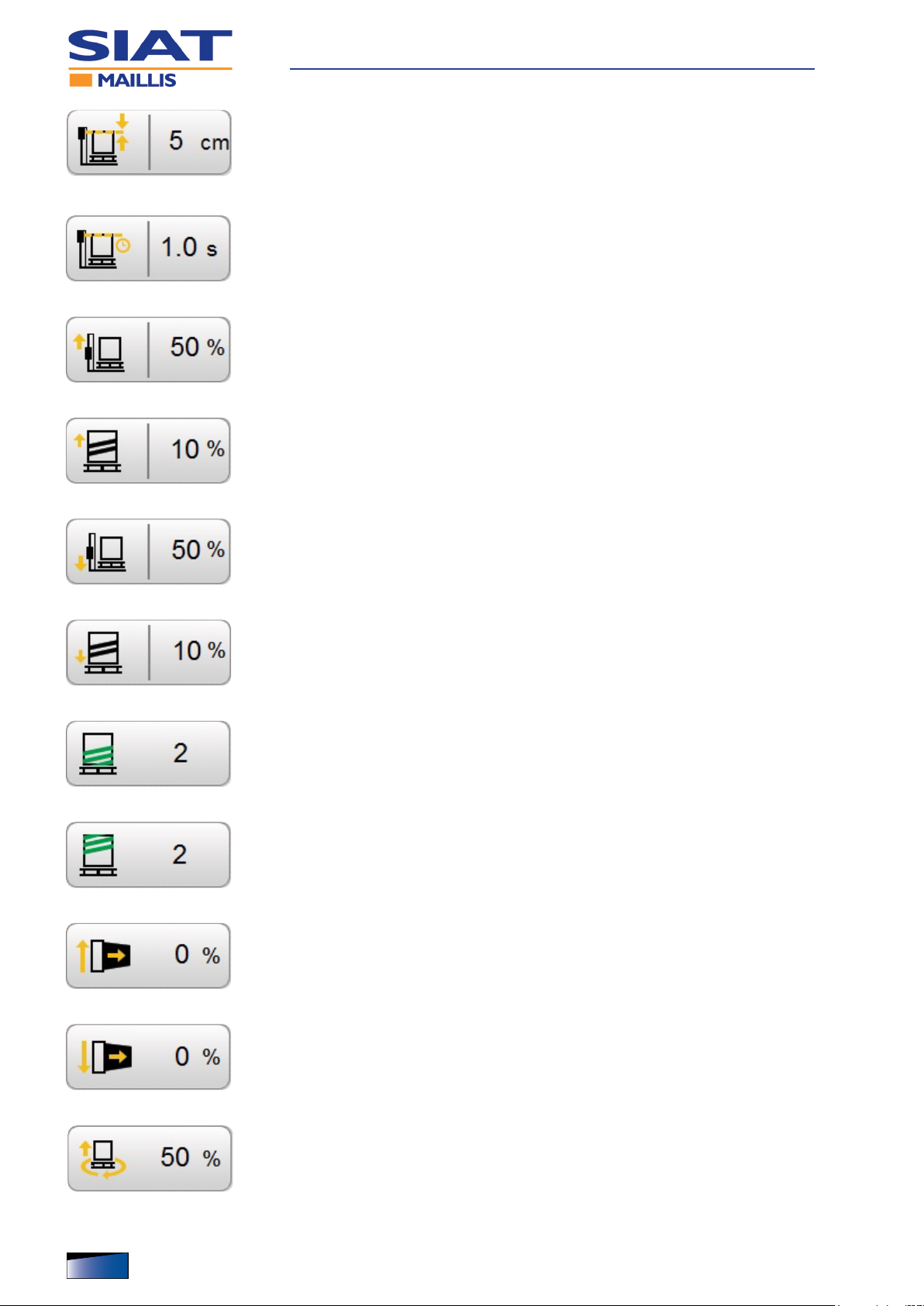
Control system
– It programmes the lifting level of the reel holding carriage , beyond
the edge of the load to be wrapped.
If you touch the image , the control will be displayed to programme
the lifting time.
– It programmes the lifting time of the reel holding carriage beyond
the edge of the load to be wrapped.
If you touch the image , the control will be displayed to programme
the lifting level.
– It programmes the lifting speed of the reel holding carriage.
The value is expressed as a percentage compared with the programmed operating speed.
If you touch the image , the control will be displayed to programme
the lm overlapping percentage during the lifting step.
– It programmes the lm overlapping percentage during the lifting of
the reel holding carriage.
If you touch the image , the control will be displayed to programme
the lifting speed of the reel holding carriage.
– It programmes the lowering speed of the reel holding carriage.
The value is expressed as a percentage compared with the programmed operating speed.
If you touch the image , the control will be displayed to programme
the lm overlapping percentage during the lowering step.
– It programmes the lm overlapping percentage during the lowe-
ring of the reel holding carriage.
If you touch the image , the control will be displayed to programme
the lowering speed of the reel holding carriage.
– It programmes the number of wrapping revolutions for the lower
reinforcement.
– It programmes the number of wrapping revolutions for the upper
reinforcement.
– It programmes lm tensioning for wrapping during the lifting of the
reel holding carriage.
– It programmes lm tensioning for wrapping during the lowering of
the reel holding carriage (Only with enabled double automatic
wrapping).
– It programmes the rotating speed of platform during the lifting of
the reel holding carriage.
The value is expressed as a percentage compared with the programmed operating speed.
72
English language Operation and maintenance manual
IDM 510-140-0

Control system
– It programmes the rotating speed of platform during the lowering
of the reel holding carriage (Only with enabled double automatic
wrapping).
The value is expressed as a percentage compared with the programmed operating speed.
– It programmes the angular position of the rotating platform at the
end of the lifting of the reel holding carriage.
If you touch the image , the control will be displayed to programme
the angular position at the end of the lowering of the reel holding
carriage.
– It programmes the angular position of the rotating platform at the
end of the lowering of the reel holding carriage.
If you touch the image , the control will be displayed to programme
the angular position at the end of the lifting of the reel holding carriage.
– It programmes the lm pre-stretch percentage during the lifting of
the reel holding carriage (only for reel holding carriage of type
DM).
– It programmes the lm pre-stretch percentage during the lowering of
the reel holding carriage (only for reel holding carriage of type DM).
The function is enabled only with double automatic wrapping.
– It selects the desired recipe in the drop-down menu.
– It programmes the height of the load to be wrapped.
If you enter the value, the photocell that detects the load height will
be disabled.
Display icons (gray background)
▀
– Instant distance (from the ground) of the reel holding carriage
IDM 510-140-0
– Instant angular position of the rotating platform
– Instant speed of lm unwinding (only for reel holding carriage of
type PW - DM).
– Tensioning of the lm for the wrapping (only for reel holding carria-
ge of type PW - DM).
English languageOperation and maintenance manual
73

Control system
– Instant speed (lifting and lowering) of the reel holding carriage
The value is expressed as a percentage compared with the programmed operating speed.
– Instant rotation speed of the platform
The value is expressed as a percentage compared with the programmed operating speed.
– Instant length of the lm unwrapped from the reel (only for reel
holding carriage of type PW - DM).
– Instant weight of the lm unwrapped from the reel (only for reel
holding carriage of type PW - DM).
– Instant length of the lm used for the wrapping
– Total lm stretching percentage (pre-stretch and tensioning)
The function is enabled only for reel holding carriages of type PW
- DM.
Non-release hold keys (shaded gray background)
▀
– It activates the lifting of the reel holding carriage.
The activation of the key will be enabled only in case of “manual
mode” operation.
– It activates the lowering of the reel holding carriage
The activation of the key will be enabled only in case of “manual
mode” operation.
Single-action keys (orange or shaded gray)
▀
– Orange background: enabled function.
– Shaded gray background: disabled function.
– It enables and disables the lm cutting device (only for machines equipped with
CW system).
– It enables and disables the advanced settings
74
English language Operation and maintenance manual
IDM 510-140-0

Control system
– It enables the single automatic wrapping (lifting of the reel holding carriage)
– It enables the double automatic wrapping (lifting and lowering of the reel holding
carriage)
– It enables and disables the working cycle with sheet feeder
– It enables and disables the Pressing Roller
– It enables and disables the lm sealing (only for machines equipped with CW
system).
– It enables and disables the creasing system during the lifting of the
reel holding carriage.
Touch the image to select the creasing type (upper or lower side of
the lm).
– It enables and disables the creasing system during the lowering of
the reel holding carriage (Only with enabled double automatic
wrapping).
Touch the image to select the creasing type (upper or lower side of
the lm).
– It loads the selected recipe in the PLC memory in order to execute it.
IDM 510-140-0
– It saves the changes to the selected recipe.
– It saves the changes in a new recipe
English languageOperation and maintenance manual
75

Language selection mode
The gure shows the points of intervention and the description shows the
procedures to be adopted.
1. Display the LANGUAGES screen (6) (See “Operator inter-
face navigation diagram (standard)”).
2. Touch the icon that corresponds to the desired language.
– The text that is to be found in all screens will immediately
update to the selected language.
Control system
Password entering mode
The gure shows the points of intervention and
the description shows the procedures to be
adopted.
1. Touch the icon A.
2. Press the eld B and enter the operator ID.
3. Press the eld C and enter the password.
4. Press the key D to conrm.
Any time you deactivate the power supply of the
machine, you must repeat the procedures to enter the password.
– To prevent operations by unauthorised peo-
ple, cancel the password as specied.
5. Touch the icon E.
6. Press the key F to conrm.
76
English language Operation and maintenance manual
IDM 510-140-0
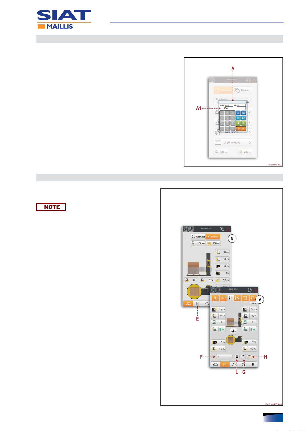
How to programme or edit the parameters
The gure shows the points of intervention and the description shows the
procedures to be adopted.
1. Stop the machine
2. Display the desired screens (one at a time) where you need
to programme or edit the values.
3. Touch the desired area.
– The keyboard A is displayed.
4. Enter the new value.
– The area A1 displays the entered value.
5. Press “ENTER” to conrm.
Control system
Recipe management
How to programme a new recipe
▀
You can programme up to 12 recipes.
1. Display the ADVANCED SETTINGS screen (8)
(See “Operator interface navigation diagram
(standard)”).
2. Press key E.
– The display shows the PARAMETER screen (9).
3. Press key L.
4. Select the desired recipe from the drop-down
menu.
5. Press the key H to duplicate the selected recipe.
6. Select the rst available ID from the drop-down
menu.
– If there are 12 are already programmed recipes,
select one of them that is not used any more in
order to overwrite it.
IDM 510-140-0
7. Touch the area F.
– The keyboard is displayed.
8. Enter the new name of the recipe and press the
“ENTER” key to conrm.
9. Change the desired parameters.
10. Press the key G to save the new recipe.
English languageOperation and maintenance manual
77

Modifying a recipe
▀
1. Display the ADVANCED SETTINGS screen (8)
(See “Operator interface navigation diagram
(standard)”).
2. Press key E.
– The display shows the PARAMETER screen (9).
3. Touch the area F.
4. Select the desired recipe from the drop-down
menu.
5. Press the “check” key to conrm.
6. Change the desired parameters.
7. Press the key G to save all changes made.
Control system
78
English language Operation and maintenance manual
IDM 510-140-0

How to load a recipe in the PLC
▀
1. Display the MAIN screen (1) (See “Operator interface navigation diagram (standard)”).
2. Press key K.
3. Touch the area A.
– The display shows the RECIPES screen (2).
4. Touch the area B.
5. Select the desired recipe from the drop-down
menu.
6. Press the key C to conrm.
– The selected recipe will be automatically loaded.
– The eld D displays the loaded recipe.
Control system
IDM 510-140-0
English languageOperation and maintenance manual
79

How to programme the bands and the wrapping reinforcements
The gure shows the screens to programme the wrapping and the reinforcements.
You can programme up to 6 different reinforcement and wrapping areas.
Control system
80
English language Operation and maintenance manual
IDM 510-140-0

no. Name Function description
9 PARAMETERS screen - Press the key to display the WRAPPING screen (9.1).
- The screen displays the controls that are used to access the reference
functions.
The summary shows (in different colours) the quantity and the type of the
9.1 WRAPPING screen
WRAPPING BANDS (LIFTING)
9.2
screen
programmed wrapping and reinforcement bands.
- Green colour: quantity of wrapping bands.
- Blue colour: quantity of reinforcement bands.
- Orange colour: quantity of reinforcement bands (with creasing system).
- The screen displays the fields that are used to programme the wrapping
parameters.
- Column A: ID of the wrapping area.
- Column B: height of the corresponding wrapping area.
- Column C: rotating speed of the platform within the corresponding wrapping
area (The value is expressed as a percentage compared with the
programmed operating speed).
- Column D: lifting speed of the reel holding carriage within the corresponding
wrapping area (The value is expressed as a percentage compared with the
programmed operating speed).
- Column E: tensioning of the film within the corresponding wrapping area.
- Column F: pre-stretch of the film within the corresponding wrapping area
(only for reel holding carriage of type PW - DM).
Control system
IDM 510-140-0
REINFORCEMENT BANDS
9.3
(WITH CREASING SYSTEM)
screen
REINFORCEMENT BANDS
9.4
(WITHOUT CREASING
SYSTEM) screen
Important
To copy the same value in all fields of a column , touch the icon in the
upper part.
- The screen displays the fields that are used to programme the wrapping
parameters.
- Column A: ID of the wrapping area.
- Column B: height of the corresponding wrapping area.
- Column E: tensioning of the film within the corresponding wrapping area.
- Column F: pre-stretch of the film within the corresponding wrapping area
(only for reel holding carriage of type PW - DM).
- Column G: quantity of reinforcement bands within the corresponding
wrapping area.
- Column H: direction of movement of the reel holding carriage within the
corresponding wrapping area.
- Column L: direction of movement of the creasing system within the
corresponding wrapping area.
Important
To copy the same value in all fields of a column , touch the icon in the
upper part.
- The screen displays the fields that are used to programme the wrapping
parameters.
- Column A: ID of the wrapping area.
- Column B: height of the corresponding wrapping area.
- Column C: rotating speed of the platform within the corresponding wrapping
area (The value is expressed as a percentage compared with the
programmed operating speed).
- Column E: tensioning of the film within the corresponding wrapping area.
- Column F: pre-stretch of the film within the corresponding wrapping area
(only for reel holding carriage of type PW - DM).
- Column G: quantity of reinforcement bands within the corresponding
wrapping area.
Important
To copy the same value in all fields of a column , touch the icon in the
upper part.
English languageOperation and maintenance manual
81

Control system
82
English language Operation and maintenance manual
IDM 510-140-0

no. Name Function description
- The screen displays the fields that are used to programme the wrapping
parameters.
- Column A: ID of the wrapping area.
- Column B: height of the corresponding wrapping area.
- Column C: rotating speed of the platform within the corresponding wrapping
area (The value is expressed as a percentage compared with the
programmed operating speed).
WRAPPING BANDS
9.5
(LOWERING) screen
- Column D: lowering speed of the reel holding carriage within the
corresponding wrapping area (The value is expressed as a percentage
compared with the programmed operating speed).
- Column E: tensioning of the film within the corresponding wrapping area.
- Column F: pre-stretch of the film within the corresponding wrapping area
(only for reel holding carriage of type PW - DM).
Important
To copy the same value in all fields of a column , touch the icon in the
upper part.
Control system
IDM 510-140-0
English languageOperation and maintenance manual
83

How to display the wrapping statistics
The gure shows the screens with wrapping statistical data.
Control system
84
English language Operation and maintenance manual
IDM 510-140-0

Control system
no. Name Function description
ADVANCED DASHBOARD
8
screen
11 COUNTERS screen
11.1 PALLET screen
11.2 FILM screen
11.3 FILM BREAKS screen The screen displays the lm break diagrams (partial and total values).
- Press the key to display the COUNTERS screen (11).
- The screen displays the controls that are used to access the reference
functions.
The areas show some machine operation statistics.
- Machine (partial and total) operating hours.
- Machine (partial and total) real wrapping hours.
- Diagrams showing machine (partial and total) operating and wrapping
percentages.
- The screen includes the controls to display the corresponding production
diagrams for the wrapped loads (partial and total values).
- Key A: control that displays the hourly production diagram.
- Key B: control that displays the daily production diagram.
- Key C: control that displays the monthly production diagram.
- The screen includes the controls to display film consumption diagrams
(partial and total values).
- Key D: control that displays the daily consumption diagram.
- Key E: control that displays the film consumption diagram for every
wrapped load.
IDM 510-140-0
English languageOperation and maintenance manual
85

How to display the Setup parameters
The gure shows the screens to programme the operation of the machine.
Control system
86
English language Operation and maintenance manual
IDM 510-140-0

Control system
The functions in the screens (12.1 - 12.2 - 12.3 - 12.4) are not described because they are intended for the Customer Assistance Service of the Manufacturer.
no. Name Function description
ADVANCED DASHBOARD
8
screen
12 TOOLS screen - Screen displays the controls that are used to access the relevant functions.
12.1 SET-UPS screen - The screen displays the set-up parameters of the machine.
12.2 ADVANCED SETTINGS screen - The screen displays the set-up parameters of the machine.
12.3 MAINTENANCE screen - The screen displays the maintenance parameters of the machine.
12.4 SETTINGS screen - The screen displays the set-up parameters of the machine.
12.5 USER MANUAL screen
12.6 LANGUAGES screen - Screen is used to select the desired language.
Press the key to display the TOOLS screen (12).
- Screen is used to read the use and maintenance manual in electronic
format. (if any)
IDM 510-140-0
English languageOperation and maintenance manual
87

Manual wrapping
The gure shows the points of intervention and the description shows the
procedures to be adopted.
1. Check whether the wrapping lm has the same chemi-
cal-physical properties as that installed in the reel holder
carriage.
– If lm characteristics appear to be different, consider wheth-
er you should adjust the lm tension.
2. Rotate main disconnector G to position “I” (ON) to activate
the power supply.
– The pilot light of button F turns on.
3. Press the push-button F.
– The pilot light of button F turns off.
4. Correctly load the new product to be wrapped in the middle
of rotating platform.
Control system
Important
Remove the lifting device.
5. Tie the trailing end of the lm to the base of the product to be
wrapped.
6. Display the MANUAL FUNCTIONS screen (3).
See “Operator interface navigation diagram (standard)”
7. Programme all wrapping parameters.
The rotation speed must be adapted to the specications of the load to be
wrapped (type and stability).
8. Press key B.
– The buzzer is activated to warn the personnel that machine operation is about to
start.
– The platform begins to rotate.
– The wrapping cycle starts when performing the lower reinforcing band.
9. When the reinforcing band is completed, press and hold button H to make reel
holder carriage rise.
Intermediate reinforcing band
▀
– Release button H when the reel holder carriage reaches the height of interest.
– Press and hold button H to wrap the remaining part.
Upper reinforcing band with reel holder carriage descent (sin-
▀
gle wrapping)
– Release button H when the reel holder carriage reaches the upper part of the
product.
– Press button C when the reinforcement band has been completed.
– Rotating platform stops in phase.
– Manually cut the lm and cause it to adhere to the wrapped product.
88
English language Operation and maintenance manual
IDM 510-140-0

– Press and hold button L to move reel holder carriage to the low position.
Upper reinforcing band with reel holder carriage descent (dou-
▀
ble wrapping)
– Release button H when the reel holder carriage reaches the upper part of the
product.
– Press and hold button L when the upper reinforcement band has been complet-
ed.
– Release button L to perform the intermediate reinforcement band.
– Press and hold button L and release it when the upper reinforcement band has
been completed.
– Press key C.
– Rotating platform stops in phase.
– Manually cut the lm and cause it to adhere to the wrapped product.
10. Remove the wrapped product.
11. Correctly load the new product to be wrapped in the middle of rotating platform.
Control system
12. Wrap the new product by following the same procedures.
Important
Keep the reel suitably relled to prevent to avoid interrupting the wrapping
due to absence of lm.
Normal stop
▀
– Manually cut the lm and cause it to adhere to the wrapped product.
– Press and hold button L to move reel holder carriage to the low position.
– Remove the wrapped product.
– Rotate electric selector G to position “O” (OFF).
IDM 510-140-0
English languageOperation and maintenance manual
89

(Single or double) automatic wrapping
The gure shows the points of intervention and the description shows the
procedures to be adopted.
1. Check whether the wrapping lm has the same chemi-
cal-physical properties as that installed in the reel holder
carriage.
– If lm characteristics appear to be different, consider wheth-
er you should adjust the lm tension.
2. Rotate main disconnector G to position “I” (ON) to activate
the power supply.
– The pilot light of button F turns on.
3. Press the push-button F.
– The pilot light of button F turns off.
4. Correctly load the new product to be wrapped in the middle
of rotating platform.
Control system
Important
Remove the lifting device.
5. Tie the trailing end of the lm to the base of the product to be
wrapped.
6. Select and activate the recipe of interest.
See “Recipe management” for further details.
7. Touch the icon M to programme the thickness of the lm
(only for reel holding carriage of type PW - DM).
8. Touch the icon N to programme the perimeter of the load to be wrapped (only for
reel holding carriage of type PW - DM).
Important
To prevent the correct operation from being compromised, programme the
values in a thorough way.
9. Press button B to start the wrapping cycle.
– If the LED of key D is ashing, press key D to move reel holding carriage to its
end-of-cycle position.
– When reel holding carriage is timed, the LED of key D turns off.
– To restart the wrapping cycle, press key B again.
– Audible warning device is activated to warn that the machine is operating.
– The machine stops as previously described, based on the selected type of wrap-
ping.
Press button C to stop wrapping; press button B to continue.
Wrapping will start at the point where it has been stopped.
– Single mode: the wrapping stops automatically with the reel holder carriage at
the upper side of the load.
Press button D to move reel holder carriage to the start of the cycle (lower part).
90
English language Operation and maintenance manual
IDM 510-140-0

– Double mode: the wrapping stops automatically with the reel holder carriage at
the starting point (lower side of the load).
10. Manually cut the lm and cause it to adhere to the wrapped product.
Important
Keep the reel suitably relled to prevent to avoid interrupting the wrapping
due to absence of lm.
11. Remove the wrapped product to be able to load the next one to wrap.
12. Correctly load the new product to be wrapped in the middle of rotating platform.
– With a product having the same features, press button B to start the wrapping
cycle.
– Wrapping is carried out in the same modes.
Normal stop
▀
– Make sure that the wrapping process has been completed.
– DO NOT control a machine stop if the wrapping cycle has not been com-
pleted.
Control system
– Manually cut the lm and cause it to adhere to the wrapped product.
– Remove the wrapped product.
– Rotate electric selector G to position “O” (OFF).
IDM 510-140-0
English languageOperation and maintenance manual
91

(Single or double) automatic wrapping with sheet feeder
The gure shows the points of intervention and the description shows the
procedures to be adopted.
1. Check whether the wrapping lm has the same chemi-
cal-physical properties as that installed in the reel holder
carriage.
– If lm characteristics appear to be different, consider wheth-
er you should adjust the lm tension.
2. Rotate main disconnector G to position “I” (ON) to activate
the power supply.
– The pilot light of button F turns on.
3. Press the push-button F.
– The pilot light of button F turns off.
4. Correctly load the new product to be wrapped in the middle
of rotating platform.
Control system
Important
Remove the lifting device.
5. Tie the trailing end of the lm to the base of the product to be
wrapped.
6. Select and activate the recipe of interest.
See “Recipe management” for further details.
7. Touch the icon M to programme the thickness of the lm
(only for reel holding carriage of type PW - DM).
8. Touch the icon N to programme the perimeter of the load to be wrapped (only for
reel holding carriage of type PW - DM).
Important
To prevent the correct operation from being compromised, programme the
values in a thorough way.
9. Press button B to start the wrapping cycle.
– If the LED of key D is ashing, press key D to move reel holding carriage to its
end-of-cycle position.
– When reel holding carriage is timed, the LED of key D turns off.
– To restart the wrapping cycle, press key B again.
– Audible warning device is activated to warn that the machine is operating.
– The machine stops as previously described, based on the selected type of wrap-
ping.
Press button C to stop wrapping; press button B to continue.
Wrapping will start at the point where it has been stopped.
– Single mode: the wrapping stops automatically with the reel holder carriage at
the upper side of the load.
– Insert the covering sheet.
– Press the key B to complete the wrapping of the covering sheet.
92
English language Operation and maintenance manual
IDM 510-140-0

Press button D to move reel holder carriage to the start of the cycle (lower part).
– Double mode: the wrapping stops automatically with the reel holder carriage at
the upper side of the load.
– Insert the covering sheet.
– Press key B.
– The machine completes the wrapping cycle and stops automatically with the reel
holder carriage at the lower side of the load.
10. Manually cut the lm and cause it to adhere to the wrapped product.
Important
Keep the reel suitably relled to prevent to avoid interrupting the wrapping
due to absence of lm.
11. Remove the wrapped product to be able to load the next one to wrap.
12. Correctly load the new product to be wrapped in the middle of rotating platform.
– With a product having the same features, press button B to start the wrapping
cycle.
Control system
– Wrapping is carried out in the same modes.
Normal stop
▀
– Make sure that the wrapping process has been completed.
– DO NOT control a machine stop if the wrapping cycle has not been com-
pleted.
– Manually cut the lm and cause it to adhere to the wrapped product.
– Remove the wrapped product.
– Rotate electric selector G to position “O” (OFF).
IDM 510-140-0
English languageOperation and maintenance manual
93

Stop in alarm conditions and restart
The gure shows the points of intervention and the description shows the
procedures to be adopted.
– All moving devices will automatically stop in case of alarm
conditions any time there is an irregular operation.
– The display shows the ALARMS screen (5).
1. Find out the causes of the anomaly.
Important
For more details on information and alarm messages, read
the attached documents.
2. Restore normal running conditions
3. Press the push-button F.
– Every solved alarm will automatically disappear.
4. Start the wrapping process.
Control system
94
English language Operation and maintenance manual
IDM 510-140-0

Emergency stop and new start-up
The gure shows the points of intervention and the description shows the
procedures to be adopted.
1. In the presence of an imminent risk press emergency button
E.
– All moving devices immediately stop.
– The pilot light of button F turns on.
2. Identify the causes that have caused the stop.
3. Restore normal running conditions
Important
The recovery operations that are not within the operator’s
eld of competence shall be carried out by authorised personnel and with recognised skills.
4. Manually cut the lm and cause it to adhere to the wrapped
product.
Control system
Decide whether to remove or to leave the already wrapped
lm.
5. Unlock the emergency stop button with a voluntary action.
6. Press the push-button F.
– The push-button lamp F shuts off.
7. Press key D.
8. Wait for the units to synch and become automatically timed.
9. Tie the trailing end of the lm to the base of the product to be wrapped.
10. Start the wrapping process.
IDM 510-140-0
English languageOperation and maintenance manual
95

Use of the weighing unit (optional)
Weighing shall be carried out ONLY with the system stopped, before starting
or after completing the wrapping.
The measured value is not valid for scal use.
– The gure shows the points of intervention and the description shows the proce-
dures to be adopted.
1. Activate the power supply of weighing unit.
2. Wait for the weighing unit to start.
3. Press the key A to reset the tare.
4. Properly place the new load to be wrapped in the
middle of the rotating platform.
– The operation is to be carried out using a forklift
truck of adequate capacity, with the forks inserted
in the intended points.
Control system
5. Remove the lifting device.
6. The display B shows the weight of the load.
For more details on the functions and controls of
the weighing unit, see the specic reference documentation.
96
English language Operation and maintenance manual
IDM 510-140-0

Calculation of lm pre-stretch
The procedure is used to check if the programmed lm pre-stretch corresponds to the real value.
– The gure shows the points of intervention and the description shows the proce-
dures to be adopted.
1. Rotate main disconnector G to position “I” (ON) to activate
the power supply.
– The pilot light of button F turns on.
2. Press the push-button F.
– The pilot light of button F turns off.
3. Introduce a sample product to be wrapped in the middle of
the rotating platform.
4. Tie the trailing end of the lm to the base of the product to be
wrapped.
5. Display the MANUAL FUNCTIONS screen (3).
See “Operator interface navigation diagram (standard)”
Control system
6. Enter the value 0% in the area H (lm tensioning).
7. Press key B.
– The buzzer is activated to warn the personnel that machine
operation is about to start.
– The platform begins to rotate.
8. Press the key C after the rotating platform has completed a
known number of wrappings (e.g. 20).
– Rotating platform stops in phase.
9. Apply the formula to nd the length of the lm that was used.
Number of wrappings x Perimeter of sample product (m) = Length of the
used lm (m)
10. Manually cut the lm.
11. Unwrap the lm that was used for the wrapping.
12. Weigh the lm using a precision scale.
13. Apply the formula to nd the weight per meter of the lm that was used.
IDM 510-140-0
Film weight (g)
Film length (m)
= Weight per meter of the used lm
14. Unwrap 10 meters of lm from the reel.
15. Weigh the lm using a precision scale.
16. Apply the formula to nd the specic weight of the lm.
Film weight (g)
Film length (m)
= Specic weight of the lm (g/m)
English languageOperation and maintenance manual
97

17. Apply the formula to nd the lm pre-stretch value.
Control system
Specic weight of the lm (g/m) - Weight per meter of the used lm (g/m)
Weight per meter of the used lm (g/m)
= Pre-stretch
18. Check that the lm pre-stretch corresponds to the set value.
Important
If the values do not match, call the manufacturer’s Technical Assistance Service.
Calculation of lm tensioning
The procedure is used to check if the programmed lm tensioning corresponds to the real value.
– The gure shows the points of intervention and the description shows the proce-
dures to be adopted.
1. Rotate main disconnector G to position “I” (ON) to activate
the power supply.
– The pilot light of button F turns on.
2. Press the push-button F.
– The pilot light of button F turns off.
3. Introduce a sample product to be wrapped in the middle of
the rotating platform.
4. Tie the trailing end of the lm to the base of the product to be
wrapped.
5. Display the MANUAL FUNCTIONS screen (3).
See “Operator interface navigation diagram (standard)”
6. Enter the value 20% in the area H (lm tensioning).
7. Press key B.
– The buzzer is activated to warn the personnel that machine
operation is about to start.
– The platform begins to rotate.
8. Use a specic tool to detect the peripheral speed of the lm
outfeed roller.
9. Use a specic tool to detect the peripheral speed of the load
to be wrapped.
10. Press key C.
– Rotating platform stops in phase.
11. Apply the formula to nd the tensioning of the lm.
Peripheral speed of the product
Peripheral speed of lm outfeed
= Film tensioning
12. Check that film tensioning corresponds to the set value.
Important
If the values do not match, call the manufacturer’s Technical Assistance Service.
98
English language Operation and maintenance manual
IDM 510-140-0
 Loading...