

Model MF4000
SIARGO MEMS FLOW SENSOR PRODUCTS
MEMS Mass Flow Meters
VB.4
© 2014 Siargo Ltd.

MEMS Mass Flow Meters
MF4000 Series
User Manual
Document No. 03-2014-2 EN
Issue date: 2014.03
Revision: VB.4
Siargo Ltd.
2041 Mission College Boulevard
Suite 250
Santa Clara, CA 95054
USA
Tel: +1(408)969.0368
Email: info@siargo.com
© Copyright 2014 by Siargo Ltd.
Siargo Ltd. and its subsidiaries reserve the rights to change the specifications and/or
descriptions without prior notice. For further information and updates, please visit:
www.Siargo.com

Contents
Features.............................................................................................................................
Introduction.......................................................................................................................
Applications........................................................................................................................
Working Principle and Package............................................................................................
Schematic of Electronics .....................................................................................................
The Meters ........................................................................................................................
Specifications.....................................................................................................................
Description.........................................................................................................................
Dimensions........................................................................................................................
Product Selection..............................................................................................................
Installation and User Interface..........................................................................................
Running Mode...................................................................................................................
Instant flow rate mode
Flow accumulation mode
Maximum / minimum mode
Menu Setting Mode..........................................................................................................
Keyboard lock
2
2
2
3
3
4
4
4
5
5
5
6
7
Flow accumulation reset
Automatic offset calibration
Response time setting
Display refresh setting
Maximum / minimum flow rate record clearing
System default retrieval
Decimal setting
Safety and Maintenance...................................................................................................
9
Wetted materials and compatibility
Safety precautions
Customer Service and Order.............................................................................................
Appendix RS232 Communication Protocol.......................................................................
10
11
Siargo MEMS Mass Flow Meters Siargo Ltd. Page 1
MEMS Mass Flow Meters
Model MF 4000
Features
Designed for gas flow in fixed flow channel of 3 mm and 8
mm, with accumulated flow
Compact design ready for manifold applications
Fast response time provides solutions for critical
applications
Excellent for electronic meters in anesthesia equipments
Exchangeable mechanical connectors for easy installation
at different applications
Intrinsic safe enclosure for wide applications
Low power consumption, can be operated by battery
Introduction
MF 4000 Series mass flow meters are designed for applications in gas flow within a flow channel diameter of 3 mm
and 8 mm, respectively. The compact design provides user friendly installation for multiple flow channel sensing
requirements. Plastic finishing with an easy change of the mechanical adaptors enables applications with different
connection thread requirements or one-touch approach. The meters can be used for electronic meters in
anesthesia equipments, environmental samplers and many other industrial applications.
The meters can be customized with flow range, gas specific requirements, user interface and others upon requests
to the manufacturer.
Applications
Environmental Monitoring
Aeration cable
Gas generated plasma monitor
Vacuum applications
Preservation of oxygen devices
Anesthesia
Ventilator
Ventilation equipment detection devices
Other industrial applications such as welding
Siargo MEMS Mass Flow Meters Siargo Ltd. Page 2
Amplifier
00
A/D
Converter
u1x1
(Pin3)VCC
MEMS
Sensor Chip
Buffer
Filter
Power
Module
Driving
Circuit
5V Power Supply
Signal Conditioning Circuit
5V / 3.3V
High-Speed 8-Bit
Microcontroller
RS232
Analog
Output
Select
(Pin2)Vout
(Pin4)GND
(Pin1)TX
(Pin5)RX
(Pin4)GND
EEPROM
D/A
Converter
u1x1
(8-24)V
DC
Display
and Key
Driver
4-digit
LED
display
Test-Key
Interface
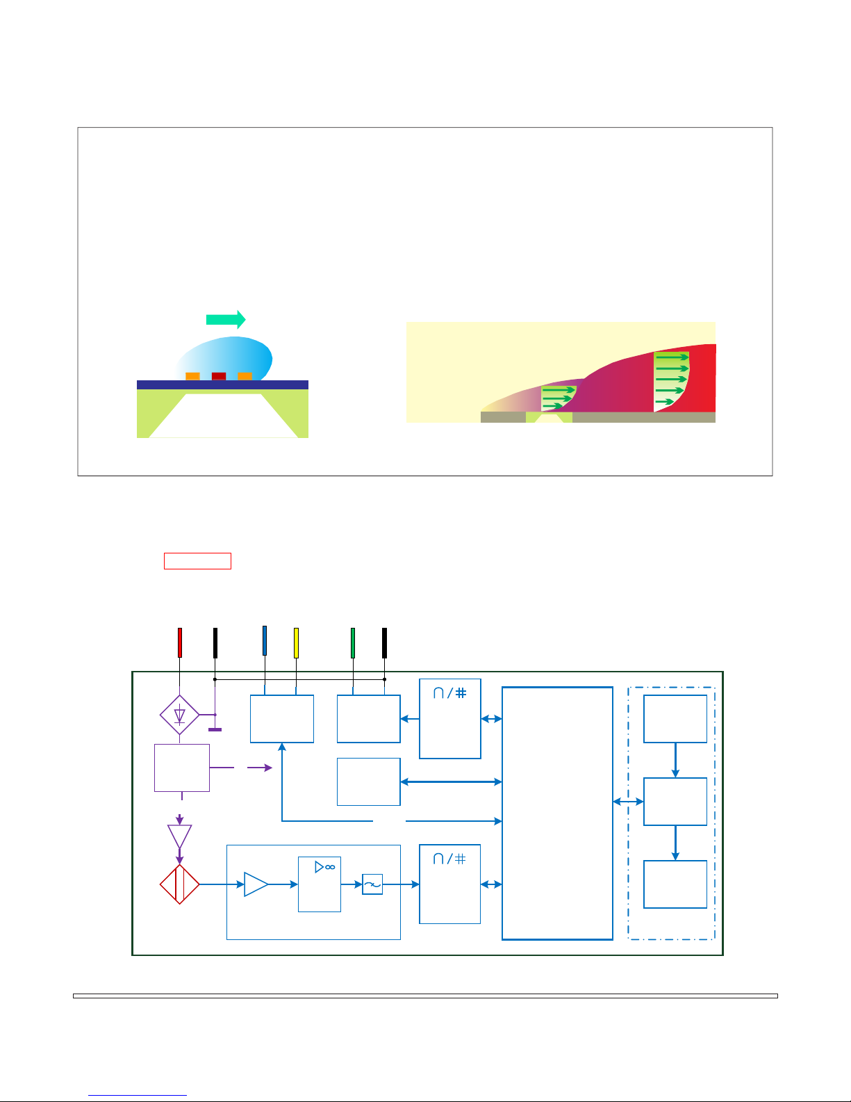
Working Principle and Package
The MEMS calorimetric sensor is installed at the flow channel wall forming a plate that serves as an
additional flow conditioner from the boundary layer configuration resulting in a laminar flow. The mass
flow measurement is established as the fluid carries heat away from the heater causing the redistribution
of the temperature field. Accurate flow rate is obtained by calibration with the standard fluid at the preset
conditions.
Schematic of Electronics
Flow direction
MF4003 MF4008
Time-averaged velocity profile boundary layer
Free stream
Laminar
Sensor
Turbulent
Siargo MEMS Mass Flow Meters Siargo Ltd. Page 3

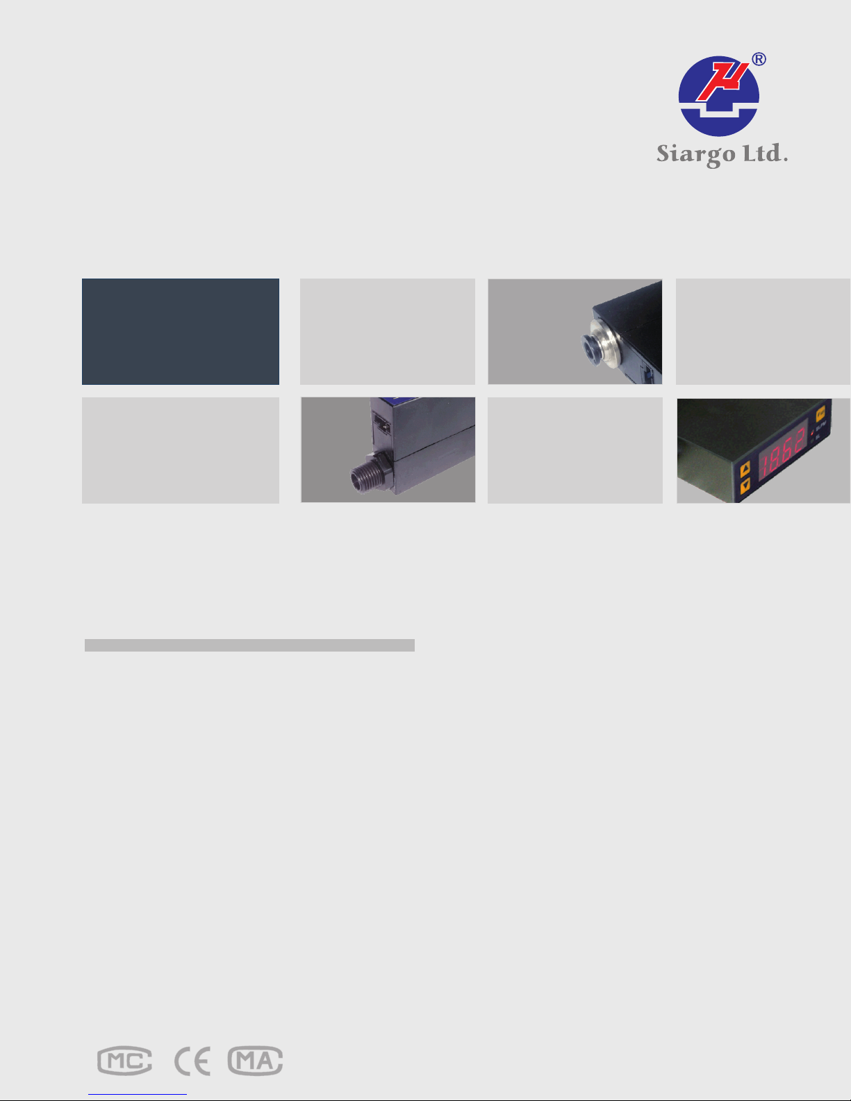
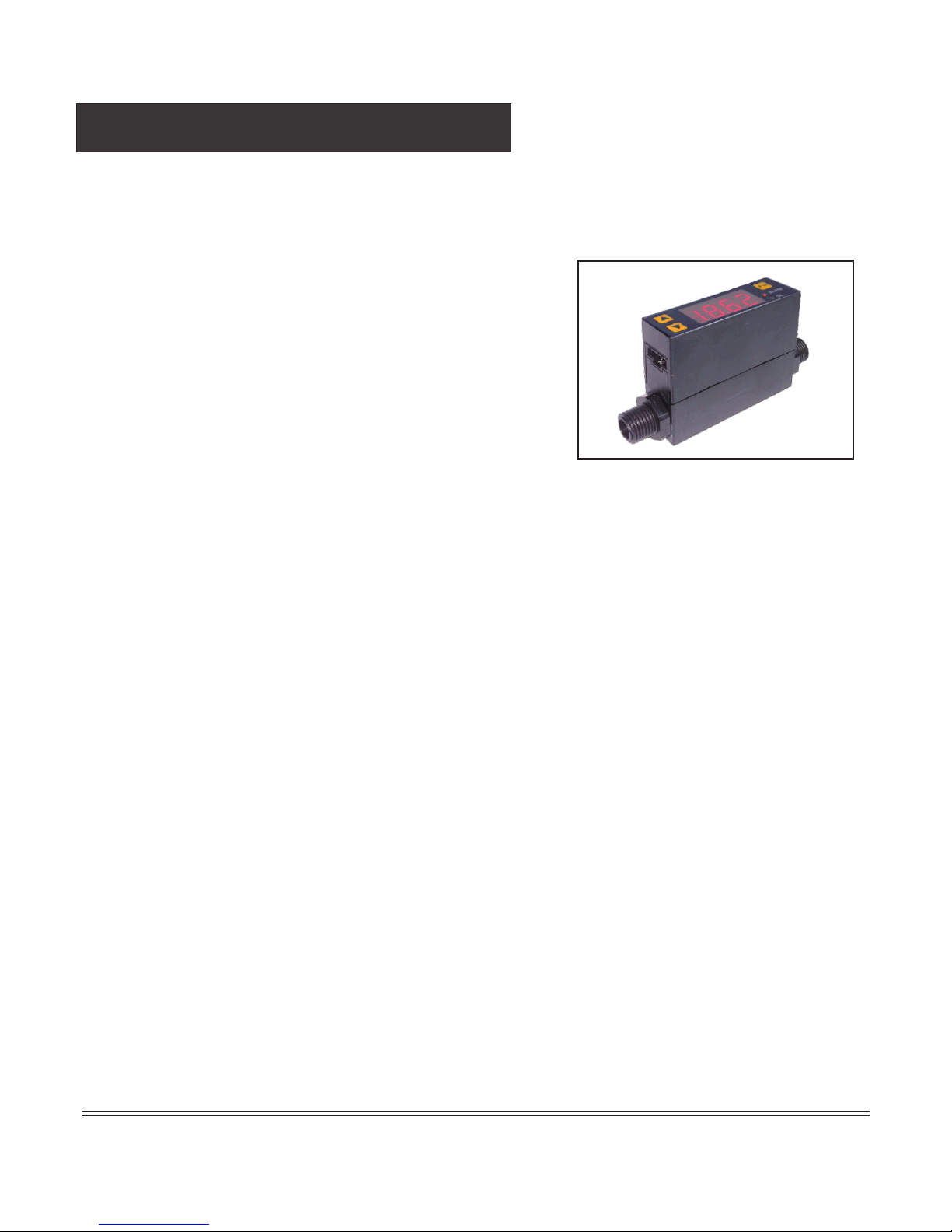
The Meters
The meters is packaged into the standard poly-carbonate enclosure with which the maximum detectable mass flow
rate can be customized within 2 SLPM to 50 SLPM by modification of the circuitry so that the various flow can be
achieved to meet customers’ best requirements. The calibration is done with air at 20°C and 1 bar pressure. It can
nonetheless be calibrated at other customer specific conditions upon requests.
Specifications
MF4003
DN
Flowrate Range
Turn-down
Accuracy %
Repeatability %
Null Shif
Output Shift % / °C
Response Time ms
Power Supply
Output
Display
Units
Display Resolution 0.001, 0.01, 0.1 selectable 0.01, 0.1 selectable SLPM
Pressure Drop 100 600 Pa
Max. Pressure MPa
Working Temperature °C
Storage Temperature °C
Humidity %RH
Mechanical Connection
Keyboard
Pins Out
Calibration
Package
Weight g
t mV
100 (Default, 10, 20, 50, 200 ,500, 1000 selectable)
Linear; RS232 / RS485, Analog 0.5~4.5Vdc
Instant flow rate: SLPM; Flow accumlation: SL
BSPT 1/4 (R 1/4), 4mm / 6mm / 8mm One-touch
74(with O4,O8 connection), 71(with O6 connection)
3 8
0 ~ 2, 3, 4, 5 0 ~ 10, 20, 30, 40, 50 SLPM
>100:1
±(1.5+0.2FS)
0.25
±30
0.12
8~24Vdc, 50mA
4-digit, 7-segment LED,2 Status LED
0.5
-10~+55
-20~+65
<95%RH (No icing or condensation)
3 keys
5 Pins, NS-TECH CD R-5
Air @ 20°C,101.325kPa
Polycarbonate
55 (with BSPT 1/4 (R 1/4) connection)
MF4008
mm
BSPT 1/4 (R 1/4)
Description
Siargo MEMS Mass Flow Meters Siargo Ltd. Page 4

Dimensions
For R 1/4 connection
MF 4003 MF4008
For One-touch connection
One-touch Connection L D
ID=8mm 91.0
ID=6mm 83.0
ID=4mm 80.0
Product Selection
MF40
* Max. flow rate number only, for example, 5 meaning full scale flow rate of 5 SLPM.
For CO and N O, selectable: 2, 3 or 4 SLPM (without 5 SLPM) for MF4003; 10, 20, 30 or 40 SLPM (without 50 SLPM) for MF4008;
2 2
** The meter standard output is analog. Digital outputs are optional.
Φ8.0
Φ6.0
Φ4.0
Gas (A - air; B - N O; C- CO ; N - N ; O - O ; R - Ar;
for other gases, please contact Siargo)
Output*** (B - RS485; C - RS232; V - analog output; Options: V / BV / CV)
Mechanical connection** (R - BSPT 1/4 (R 1/4);
O4/O6/O8 - 4 mm/6 mm/8 mm one-touch connector;
for MF4003 - R, O4, O6 and O8 selectable; for MF4008 - R selectable.)
Max. Flow Rate* (for MF4003 - 2, 3, 4 or 5 SLPM;
for MF4008 - 10, 20, 30, 40 or 50 SLPM)
Product Series Name (03-DN3,08-DN8)
2 2 2 2
Siargo MEMS Mass Flow Meters Siargo Ltd. Page 5

Installation and User Interface
C▄◘Ŏ
Accumulation
4 Less
Significant Digits
(LED Display)
Instant Flow
Rate
Flow
Accumulation
4 More
Significant Digits
(LED Display)
Auto change
Maximum Flow
Rate
(LED Blink)
Minimum Flow
Rate
(LED Blink)
I-LED on II-LED on
Push and keep for
more than 2sec
Push
/
/
Push
Fn
I-LED on
II-LED on
RUNNING MODE
Power
on
Push
The product at the time of shipment is fully inspected for product quality and meets all safety
requirements. Additional safety measures during the installation should be applied. This includes, but is
not limited to leakage verification procedures if applicable, standard ESD (electrostatic discharge)
precautions, and DC voltage precautions. Other tasks such as calibration, part replacement, repair, and
maintenance must only be performed by trained personnel. Upon requests, manufacturer will provide
necessary technical support and/or training of the personnel.
Do not open the product cover or alter any part of the product. Any such actions will forfeit the terms of
the warranty and cause the liability to any damages thereafter.
The interface is defined in the table below:
Pin Colour Definition
1 Blue TX, RS232 Transmit (output) / RS48 B5
2 Green Vout, Analog output
3 Red VCC, Power supply (8 - 24 Vdc)
4 Black GND, Ground
5 Yellow RX, RS232 Receive (input) / RS48 A5
NOTE: Upon open the package, if any component listed above is missing or any visible mechanical
damage is found, please contact supplier or distributors immediately. For additional assistance
of installation, please contact supplier or customer service.
Running Mode
The display consists of a 4-digit LED panel and two LED
indicators (i.e., I-LED and II-LED). Under the running mode,
the 4-digit LED panel will show Instant flow rate, flow
accumulation, or maximum/minimum flow rates. There
are three different display modes: instant flow rate mode,
flow accumulation mode, and maximum/minimum mode.
The two LED indicators will illustrate which display mode is
undergoing.
F
Instant flow rate mode
1. This is the default display mode, in which the two LED indicators are off.
2. The instant flow rate is displayed by the 4-digit LED panel with one decimal digit available.
The flow rate unit is SLPM.
3. When the flow rate exceeds the maximum allowable flow rate, I-LED will blink.
4. When the flow rate exceeds the minimum allowable flow rate, II-LED will blink.
Siargo MEMS Mass Flow Meters Siargo Ltd. Page 6
Flow

5. When the flow rate exceeds the maximum displayable reading, both I-LED and II-LED will
blink simultaneously, which implies that the reading is incorrect (since the reading has been
rounded off to fit the display, although the measurement may still be correct).
Flow accumulation mode
1. In this display mode, the two LED indicators are turned on.
2. The flow accumulation is displayed as an 8-digit numeric number in a time-division scheme.
When the first LED indicator (I-LED) turns on, the 4-digit LED panel displays the more
significant digits of the flow accumulation. After 1 second, the second LED indicator (II-LED)
turns on and the 4-digit LED panel displays the less significant digits of the flow accumulation.
3. The flow accumulation unit is SL. The flow accumulation reading can be reset to zero by a
key operation.
NOTE: The flow accumulation will be saved every 3 minutes. For instance:
1, The flow accumulation will not be saved if power off @ 2 minutes.
2, The flow accumulation will be the value of 33 minutes if power off @ 34 minutes.
Maximum / minimum mode
1. In this mode, the maximum flow rate and the minimum flow rate (since the last power-on or
the last maximum/minimum flow rate resetting) will be displayed.
2. When the maximum flow rate is shown, I-LED will turn on and the 4-digit LED panel will blink.
3. When the minimum flow rate is shown, II-LED will turn on and the 4-digit LED panel will blink.
Menu Setting Mode
Under the menu setting mode, various operations including keyboard lock/unlock, flow accumulation
reset, automatic offset calibration, gas selection, response time setting, display refresh setting,
maximum/minimum flow rate reset can be performed.
Keyboard lock
1. Prevent unintentional modifications of system parameters.
2. After the keyboard is locked, the user will be unable to perform any other menu settings
unless the keyboard is unlocked by the user.
Flow accumulation reset
Reset the flow accumulation reading to 0 SL, and the flow accumulation counts re-starting
at 0 SL.
Automatic offset calibration
Perform offset calibration, which is used for resolving the possible offset drifting after certain
period of operation.
NOTE: Before performing automatic offset calibration, please ensure that the gas in the pipe is
static, i.e., at zero flow. Otherwise, it may cause inaccuracy during the measurement.
Siargo MEMS Mass Flow Meters Siargo Ltd. Page 7

Instant Flow
Rate
(LED Display )
Push and keep for
Keyboard
Unlock
0.unL(Blink)
Fn
Push
Keep the Flow
Accumulation
1.oFF(Blink)
Fn
Push
Fn
more than 2 sec
Push
/
Push Push
/
Keyboard
Locked
0.Loc(Blink )
Clear the Flow
Accumulation
1.on(Blink )
Push
MENU SETTING MODE
Fn
Flow
Fn
accumulation
Zeroing
Donđt perform
offset calibration
2.oFF(Blink)
Fn
Push
Response
time=10ms
4.001(Blink)
Fn
Push
Display refresh
time =250ms
5.025(Blink)
Fn
Push
Keep Max ./Min.
Flow Rate
6.oFF(Blink)
Fn
Push
Keep current
Setting
7.oFF(Blink)
Fn
Push
No decimal
digits
8. 0(Blink )
Push
/
Perform Offset
Calibration
2.on(Blink )
Push
Fn
Automatic offset
calibration
Response
time=1000ms
4.100(Blink)
Push
Fn
Push
/
Push
/ / / /
Response
time=20ms
4.002(Blink)
Push
Response
time=50ms
4.005(Blink)
Push
Response
time=100ms
4.010(Blink)
Push
Fn
Push
/
/
Display refresh
time =500ms
5.050(Blink)
/
Display refresh
time =1s
5.100(Blink)
/
Display refresh
time =2s
5.200(Blink)
PushPushPush
Push
Fn
Clear Max ./Min.
/
Flow Rate
6.on(Blink )
PushPush
Fn
Clear Max ./Min.
Flow Rate
Push
Fn
/
System default
retrieval
7.on(Blink )
PushPush
Fn
System default
retrieval
Push
Fn
Push
/
Push
/
Decimal digits =1
8. 1(Blink )
Push
/
Decimal digits =2
8. 2(Blink )
Push
/
Decimal digits =3
8. 3(Blink )
Push
/
Push
Response
time=500ms
4.050(Blink)
Push
Response
time=200ms
4.020(Blink)
/
Fn Fn Fn Fn
Push Push
Siargo MEMS Mass Flow Meters Siargo Ltd. Page 8
Push
Push

Response time setting
1. Set the response time of the analog output signal;
2. Set the time interval for the digital output signal;
3. After each setting is completed, it is in effect immediately. However, it is stored in the
internal EEPROM only when a new menu operation is invoked. If the power is off before a
new menu operation is invoked, the setting will be discarded without being stored.
Display
Response Time
Display refresh setting
4.001 4.002 4.005 4.010 4.020 4.050 4.100
10 ms 20 ms 50 ms 100 ms 200 ms 500 ms 1000 ms
1. Set the time interval for the display refresh;
2. After each setting is completed, it is in effect immediately. However, it is stored in the internal
EEPROM only when a new menu operation is invoked. If the power is off before a new menu
operation is invoked, the setting will be discarded without being stored.
Display
Refresh Time
Maximum / minimum flow rate record clearing
5.025 5.050 5.100 5.200
250 ms 500 ms 1000 ms 2000 ms
1. Reset the maximum/minimum flow rate register, and the maximum/minimum flow rates will
be re-starting from the initial state.
2. The maximum/minimum flow rate record will be automatically reset when the meter is
power off.
System default restore
Reset all the system parameters to the default values specified in the factory.
Decimal setting
Set the number of decimal digits.
NOTE: The maximum number of decimal digits is depended on the maximum flow rate. For
example, when the maximum flow rate is 10,20,30,40,50 L/min, the number of decimal
digits can be at most 2, e.g., 49.99 L/min.
Safety and Maintenance
Wetted materials and compatibility
The meter body is made of medical compatible plastics. Sensor comprise of silicon, silicon nitride and
silicon dioxide and the sensor surfaces are passivated with silicon nitride and silicon dioxide. The
electronic sealing is provided by RTV (room temperature vulcanizing) silicone sealant WR-704 composed
of HOCH3 (SiO) nCH3H.
Siargo MEMS Mass Flow Meters Siargo Ltd. Page 9

Safety precautions
The product is designed for use with general purpose gases such as air and nitrogen. It is advised that the
products are best used for non-explosive clean gases. The sensors cannot be used for gas metrology of
fluoride or fluoride containing gases. For updates of the product certification information, please contact
manufacturer or visit www.Siargo.com. Use for other gases such as extreme corrosive and toxic may
cause the product malfunctioning or even severe damages. The product sealing is ensured to work under
working pressure of 0.5 MPa and is leakage proof before the shipment. But cautions and further leakage
test are important at installation as well since any leakage could cause severe safety issue. The power
supply for this product is 8~24 VDC, all precautions and measures for electrical voltage handling must
apply.
Attention: Any alternation and/or improper use of the product without the permission of the
manufacturer can cause unpredicted damages and even injuries or other severe situations. Siargo Ltd or
any of its employees, subsidiaries shall not be hold and indemnified against such consequences due to
such circumstances via improper use of the product.
All maintenance of the meter should be done by trained and certified personnel by Siargo, Ltd. products.
Customer Service and Order
Siargo Ltd.
2041 Mission College Blvd, Ste 250, Santa Clara, California 95054 USA, info@Siargo.com; +01(408)969-0368
In Japan, please contact
Marubeni Information Systems Co., Ltd.
Device Solutions Department, 3-12-18 Shibuya, Shibuya-ku, Tokyo 150-0002; +81-3-5778-8661
Siargo@Marubeni-sys.com
Siargo MEMS Mass Flow Meters Siargo Ltd. Page 10

Appendix RS232 Communication Protocol
Serial Port Settings
PROPERTIES RS232 RS485
Physical interface TIA/EIA-232-E TIA/EIA-485-A
Transmission cable 3-core shielded cable
Cable length ≤ 3m ≤ 1200m
Communication interface UART, Half-duplex
Data link protocol point to point point to point; point to multiple
Baud rate (Bits per
second)
Port
Setting
Data bits 8 bits
Frame_header 1 bit Mark
Parity
Error checking method XOR
Others 1 bit Space
Stop bits 1 bit
Flow control None
38400 bps
Protocol Structure
This protocol includes three working layers: physical
layer, data link layer, and user layer.
Physical layer protocol
Every byte contains 11bits, which is defined as
follows:
Start_bit D0 D1 D2 D3 D4 D5 D6 D7 D8 Stop_bit
a) Start_bit:
1bit, a logic low;
b) Data bits (D0~D7):
8 bits, representing the data byte under
transmission, which is ordered from the
least-
significant digit to the most-significant digit;
c) Frame_header flag (D8):
1bit, a flag to indicate whether the data byte
under transmission is a type of datum or
frame_header.
* When transmitting a frame_header (or address)
from master, D8 must be set to 1. When
transmitting another datum (such as command
code, data length, data segment, checksum or
frame_end), D8 can be set to 0 or 1. We suggest
customer set D8 to 0, when transmitting other
datum;
* For the byte sent from MF4000, D8 is always 0;
d) Stop_bit:
1bit, a logic high.
Data link layer protocol
Both the master and slave (MF4000) have the same
frame format, each byte of which is hexadecimal (nonASCII code). Specifically, the frame format is defined
as below:
Frame_header 1 byte
Command code 1 byte
Length 1 byte
Data Variable-length
Checksum 1 byte
Frame_end 1 byte
a) Frame_header:
For RS-232, this frame header is a constant byte:
0x9D, representing the start of a data frame.
For RS-485, this frame header is the address of
the slave under query (i.e., the salve device to
whom the data is sent). If the slave responds, the
slave will need to return its own slave address.
The allowable slave address code is an integer
between 1~128. When this frame header is set to
0, it is in the broadcast mode, in which all the
slave devices will be in effective to accept the
data but not be allowed to return their addresses
after receiving the data.
b) Command code:
The commend code, an integer between 0 and
255 excepting 0x9D, defined in the User Layer to
achieve various functionality.
c) Length:
The length of the data, an integer between 0 and
102 depending on the commend code. If the
command code has no data, the length should be
0. If the MF4000 unit detects the length larger
than 102, the MF4000 unit will not send any
response;
d) Data:
The body of the data, whose length varies
depending on the command code. If the
command code has no data, the length should be
0;
e) Checksum:
XOR;
f) Frame_end:
0x0D;
g) Overtime
1sec. This is to prevent MF4000 from running into
a deadlock because of the master failures or
communication failures. When MF4000 receives
a correct byte, a timer will begin. If MF4000 does
not receive other correct byte within 1sec, it will
interrupt the communication and prepare to
receive next byte. The interval time from MF4000
to the master is less than 10msec (which can be
used for the master to judge the overtime).
Siargo MEMS Mass Flow Meters Siargo Ltd. Page 11

Appendix RS232 Communication Protocol
User layer protocol
Command Code F0 Read instant flow rate
Master query 9D F0 01 08 CRC 0D
MF4000 response 9D F0 03 FRH FRM FRL CRC 0D
Description
Command Code FF Read the sensor series number
Master query 9D FF 00 CRC 0D
Mf4000 response
Description
Command Code 02 Change the response time
Master query 9D 02 02 RTH RTL CRC 0D
MF4000 response 9D 02 01 STATE CRC 0D
Description
Command Code 03 Change the GDCF of the sensors
Master query 9D 03 02 GDCFH GDCFL CRC 0D
MF4000 response 9D 03 01 STATE CRC 0D
Description
Command Code 72 Calibrate sensor offset (Auto)
Master query 9D 72 01 55 CRC 0D
MF4000 response 9D 72 02 OFFSETH OFFSETL CRC 0D
Description
Command Code 78 Reset all the parameters to default.
Master query 9D 78 01 55 CRC 0D
MF4000 response 9D 78 01 STATE CRC 0D
Description
3 bytes.
FR (Instant flow rate) = (FRH * 65536 + FRM * 256 + FRL)/ 1000;
Unit: SLPM,Decimal digits: 3.
9D FF 0C SN1 SN2 SN3 SN4 SN5 SN6 SN7 SN8 SN9 SN10 SN11
SN12 CRC 0D
12 bytes.
It is the series number of the sensor made up of 12 ASCII
characters.
1 byte.
Unit: msec.
RT ( response time ) = RTH * 256 + RTL;
Selectable: 10, 50, 100, 200, 500 and 1000.
STATE: if the operation is successful, STATE = 1, otherwise STATE
= 0.
1 byte.
GDCF = GDCFH * 256 + GDCFL.
STATE: if the operation is successful, STATE = 1, otherwise STATE
= 0.
2 bytes.
Ensure there is no flow in the sensor pipe during calibrating offset.
Offset = OFFSETH * 256 + OFFSETL.
The normal range is from -32767 to +32767.
1 byte.
Reset all the parameters to default (Automatic)
1, Reset the default response time (10msec);
2, Reset the default GDCF (1000);
3, Reset the default offset.
Command Code 82 Read the response time
Master query 9D 82 00 CRC 0D
MF4000 response 9D 82 02 RTH RTL CRC 0D
Description
Command Code 83 Read GDCF
Master query 9D 83 00 CRC 0D
MF4000 response 9D 83 02 GDCFH GDCFL CRC 0D
Description
2 bytes.
RT ( response time ) = RTH * 256 + RTL;
2 bytes.
GDCF = GDCFH * 256 + GDCFL.
Flow chart (master to MF4000)
Set frame_header
flag to 1(D8 = 1)
Send
frame_header
No
No
No
Set frame_header
flag to 0(D8 = 0)
Send command
code and length
Send data
All data have been
sent?
Yes
Send checksum
and frame_end
Yes
Receive frame_head,
command code and
length
Receive data
All data have been
received?
Yes
Receive checksum
and frame_end
Is checksum correct?
Yes
Is frame_end correct?
Yes
Processing data
Continue to send
other frame?
No
Over
Siargo MEMS Mass Flow Meters Siargo Ltd. Page 12
 Loading...